Embed Size (px)
Citation preview
1
Easy! Smooth!
LT Type A LT-3300T/LT-3301L
Replacement Guidebook
3rd Edition: October. 2012
Copyright © 2012.10 Digital Electronics Corporation. All Rights Reserved.
2
Preface
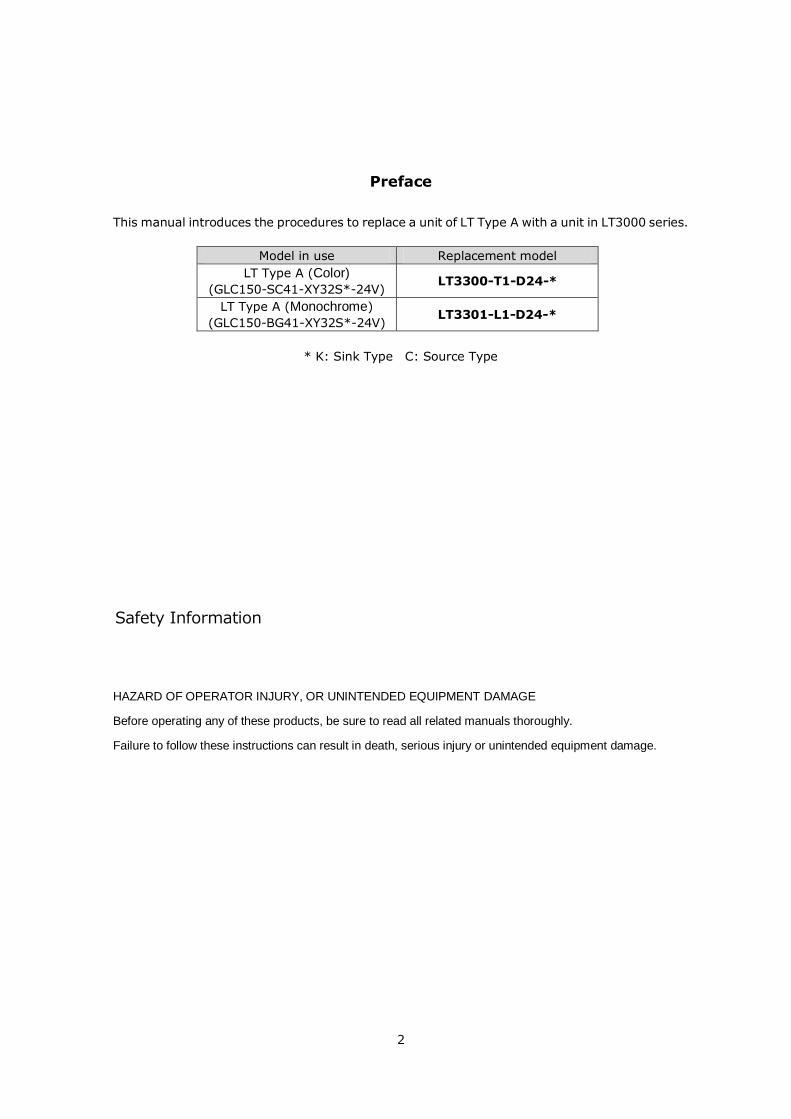
This manual introduces the procedures to replace a unit of LT Type A with a unit in LT3000 series.
Model in use Replacement model
LT Type A (Color)
(GLC150-SC41-XY32S*-24V) LT3300-T1-D24-*
LT Type A (Monochrome)
(GLC150-BG41-XY32S*-24V) LT3301-L1-D24-*
* K: Sink Type C: Source Type
Safety Information
HAZARD OF OPERATOR INJURY, OR UNINTENDED EQUIPMENT DAMAGE
Before operating any of these products, be sure to read all related manuals thoroughly.
Failure to follow these instructions can result in death, serious injury or unintended equipment damage.
3
Contents
Preface 2
Contents 3
Chapter 1 Specification Comparison 5
1.1 Specifications of LT Type A and LT-3300T/3301L 5
Functional specifications/General specifications 5
DIO Interface (Input) Specifications 6
DIO Interface (Output) Specifications 7
Chapter 2 Compatibility of Hardware 8
2.1 Locations of connectors 8
2.2 Touch Panel Specifications 9
2.3 Panel Cutout Dimensions 9
2.4 Transfer cable 9
2.5 Interface 9
2.5.1 Alarm Output Interface 9
2.5.2 DIO Interface 9
2.6 Peripheral units and options 10
2.6.1 Barcode reader connection 10
2.6.2 Printer Connection 10
2.7 Power Connector 10
2.8 Power Consumption 10
2.9 Materials/Colors of the body 10
4
Chapter 3 Replacement Procedure 11
3.1 Work Flow 11
3.2 Preparation 12
3.3 Receive screen data from LT Type A 12
3.4 Convert screen data with the Project Converter 16
3.5 Transfer the project file to LT-3300T/LT-3301L. 21
3.6 Differences of software 26
3.6.1 Differences after conversion 26
5
Chapter 1 Specification Comparison
1.1 Specifications of LT Type A and LT-3300T/3301L
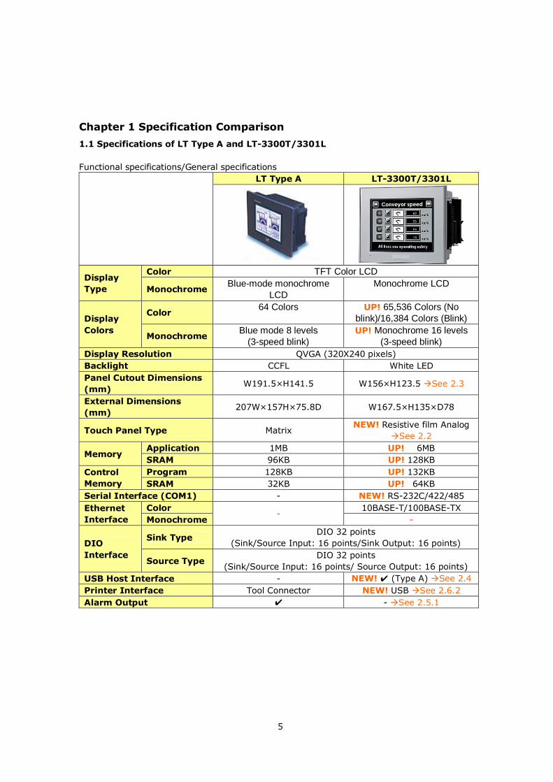
Functional specifications/General specifications
LT Type A LT-3300T/3301L
Display
Type
Color TFT Color LCD
Monochrome Blue-mode monochrome
LCD
Monochrome LCD
Display
Colors
Color 64 Colors UP! 65,536 Colors (No
blink)/16,384 Colors (Blink)
Monochrome Blue mode 8 levels
(3-speed blink)
UP! Monochrome 16 levels
(3-speed blink)
Display Resolution QVGA (320X240 pixels)
Backlight CCFL White LED
Panel Cutout Dimensions
(mm) W191.5×H141.5 W156×H123.5 See 2.3
External Dimensions
(mm) 207W×157H×75.8D W167.5×H135×D78
Touch Panel Type Matrix NEW! Resistive film Analog
See 2.2
Memory Application 1MB UP! 6MB
SRAM 96KB UP! 128KB
Control
Memory
Program 128KB UP! 132KB
SRAM 32KB UP! 64KB
Serial Interface (COM1) - NEW! RS-232C/422/485
Ethernet
Interface
Color -
10BASE-T/100BASE-TX
Monochrome -
DIO
Interface
Sink Type DIO 32 points
(Sink/Source Input: 16 points/Sink Output: 16 points)
Source Type DIO 32 points
(Sink/Source Input: 16 points/ Source Output: 16 points)
USB Host Interface - NEW! ✔ (Type A) See 2.4
Printer Interface Tool Connector NEW! USB See 2.6.2
Alarm Output ✔ - See 2.5.1
6
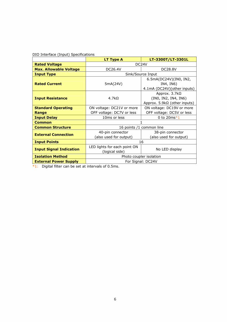
DIO Interface (Input) Specifications
LT Type A LT-3300T/LT-3301L
Rated Voltage DC24V
Max. Allowable Voltage DC26.4V DC28.8V
Input Type Sink/Source Input
Rated Current 5mA(24V)
6.5mA(DC24V)(IN0, IN2,
IN4, IN6)
4.1mA (DC24V)(other inputs)
Input Resistance 4.7kΩ
Approx. 3.7kΩ
(IN0, IN2, IN4, IN6)
Approx. 5.9kΩ (other inputs)
Standard Operating
Range
ON voltage: DC21V or more
OFF voltage: DC7V or less
ON voltage: DC19V or more
OFF voltage: DC5V or less
Input Delay 10ms or less 0 to 20ms*1
Common 1
Common Structure 16 points /1 common line
External Connection 40-pin connector
(also used for output)
38-pin connector
(also used for output)
Input Points 16
Input Signal Indication LED lights for each point ON
(logical side) No LED display
Isolation Method Photo coupler isolation
External Power Supply For Signal: DC24V
*1: Digital filter can be set at intervals of 0.5ms.
7
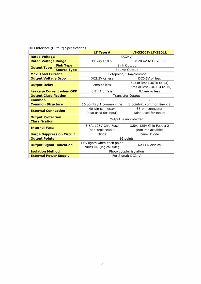
DIO Interface (Output) Specifications
LT Type A LT-3300T/LT-3301L
Rated Voltage DC24V
Rated Voltage Range DC24V±10% DC20.4V to DC28.8V
Output Type Sink Type Sink Output
Source Type Source Output
Max. Load Current 0.2A/point, 1.6A/common
Output Voltage Drop DC2.5V or less DC0.5V or less
Output Delay 2ms or less 5μs or less (OUT0 to 13)
0.5ms or less (OUT14 to 15)
Leakage Current when OFF 0.4mA or less 0.1mA or less
Output Classification Transistor Output
Common 1 2
Common Structure 16 points / 1 common line 8 points/1 common line x 2
External Connection 40-pin connector
(also used for input)
38-pin connector
(also used for input)
Output Protection
Classification Output is unprotected
Internal Fuse 3.5A, 125V Chip Fuse
(non-replaceable)
3.5A, 125V Chip Fuse x 2
(non-replaceable)
Surge Suppression Circuit Diode Zener Diode
Output Points 16 points
Output Signal Indication LED lights when each point
turns ON (logical side) No LED display
Isolation Method Photo coupler isolation
External Power Supply For Signal: DC24V
8
Chapter 2 Compatibility of Hardware
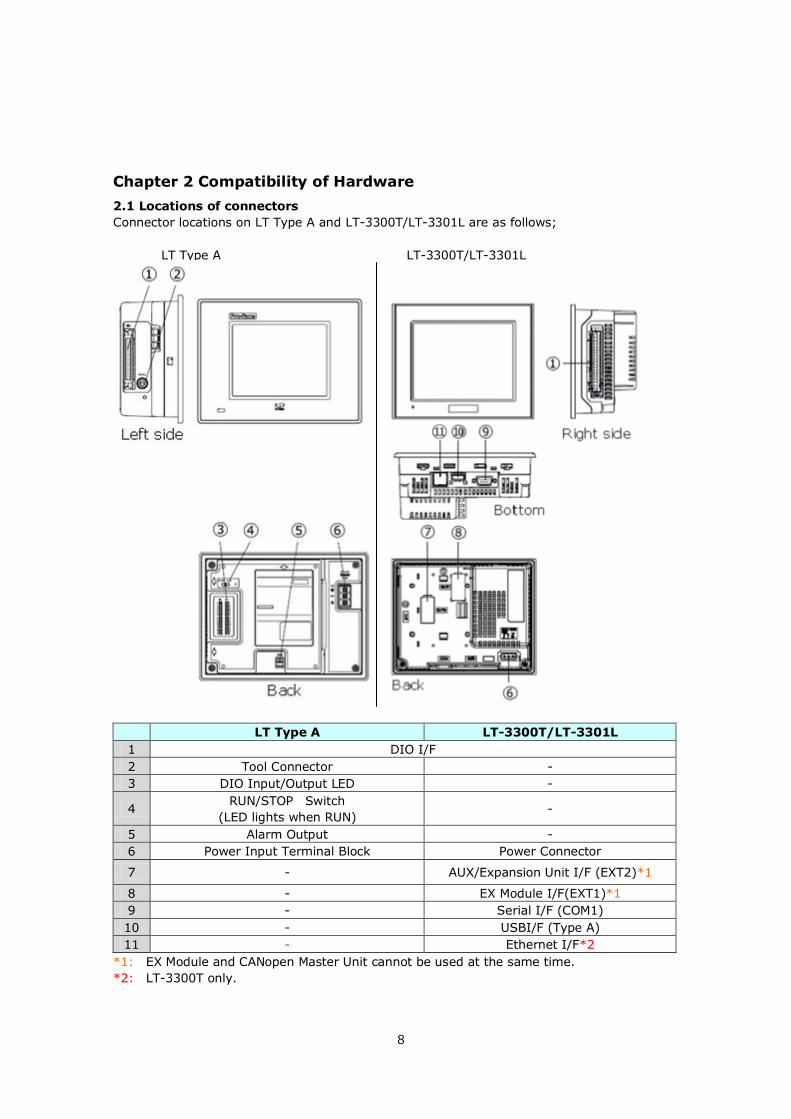
2.1 Locations of connectors
Connector locations on LT Type A and LT-3300T/LT-3301L are as follows;
LT Type A LT-3300T/LT-3301L
LT Type A LT-3300T/LT-3301L
1 DIO I/F
2 Tool Connector -
3 DIO Input/Output LED -
4 RUN/STOP Switch
(LED lights when RUN) -
5 Alarm Output -
6 Power Input Terminal Block Power Connector
7 - AUX/Expansion Unit I/F (EXT2)*1
8 - EX Module I/F(EXT1)*1
9 - Serial I/F (COM1)
10 - USBI/F (Type A)
11 - Ethernet I/F*2
*1: EX Module and CANopen Master Unit cannot be used at the same time.
*2: LT-3300T only.
9
2.2 Touch Panel Specifications
The touch panel type for LT3000 series is 'Resistive Film (Analog)'.
The resistive film analog type recognizes only the first-touched point and doesn't recognize the
second-touched point when two different points are touched at the same time.
If you have applied the two-point touch input on LT Type A, we recommend you to change to the
one-point touch input using the switch delay function of GP-Pro EX.
2.3 Panel Cutout Dimensions
The size of LT-3300T/LT-3301L is smaller. The panel cutout dimensions of LT-3300T/LT-3301L
are different from those of LT Type A. Attachment (model: CA4-ATM5-01) for installing
LT-3300T/LT-3301L is available and you can use it when replacing LT Type A with
LT-3300T/LT-3301L.
2.4 Transfer cable
To transfer screen data to LT-3300T/LT-3301L, use a USB cable or Ethernet.
Use a transfer cable for LT-3300T/LT-3301L (model number: CA3-USBCB-01). Commercial USB
cables cannot be used. Please note that the cables (model number: GPW-CB02, GPW-CB03,
GP430-CU02-M) for LT Type A cannot be used for LT-3300T/LT-3301L.
2.5 Interface
2.5.1 Alarm Output Interface
Alarm Output Function is not supported by LT-3300T/LT-3301L. Please note that the Alarm
Output that is used for LT Type A cannot be used.
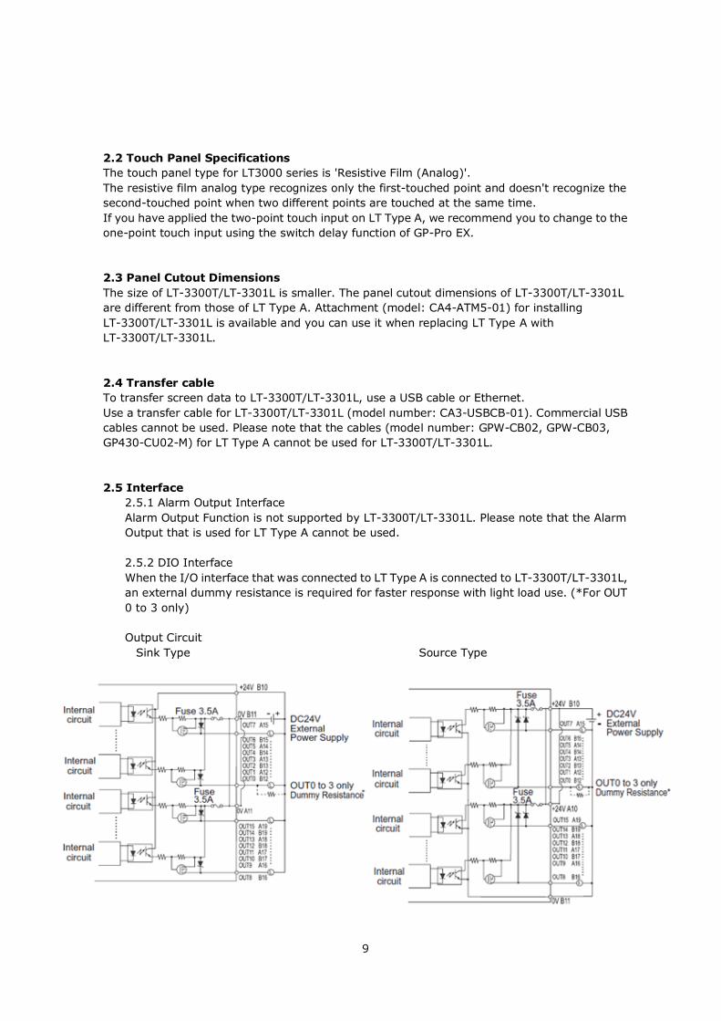
2.5.2 DIO Interface
When the I/O interface that was connected to LT Type A is connected to LT-3300T/LT-3301L,
an external dummy resistance is required for faster response with light load use. (*For OUT
0 to 3 only)
Output Circuit
Sink Type Source Type
10
2.6 Peripheral units and options
2.6.1 Barcode reader connection
LT-3300T/LT-3301L is not equipped with a tool port. The barcode reader that was connected
to the tool port on LT Type A before replacement cannot be used. But LT-3300T/LT-3301L
allows you to connect a barcode reader on its USB interface (Type A).
For models LT-3300T/LT-3301L supports, see [Otasuke Pro!]
(http://www.pro-face.com/otasuke/).
2.6.2 Printer Connection
LT-3300T/LT-3301L is not equipped with a tool port. The printer that was connected to the
tool port on LT Type A before replacement cannot be used. But LT-3300T/LT-3301L allows
you to connect a printer on its USB interface (Type A).
For models LT-3300T/LT-3301L supports, see [Otasuke Pro!]
(http://www.pro-face.com/otasuke/).
2.7 Power Connector
The power connector on LT-3300T/LT-3301L is a screw lock type. If you replace LT Type A with
LT-3300T/LT-3301L, note that the power supply terminals are different.
2.8 Power Consumption
The power consumption of LT Type A is different from that of LT-3300T/LT-3301L.
LT Type A 20W or less
LT-3300T/LT-3301L 27W or less
For the detailed electric specifications, see the hardware manual.
2.9 Materials/Colors of the body
The body material of LT-3300T/LT-3301L is a resin type like LT Type A. The material texture is
almost the same, but the color is different.
11
Chapter 3 Replacement Procedure
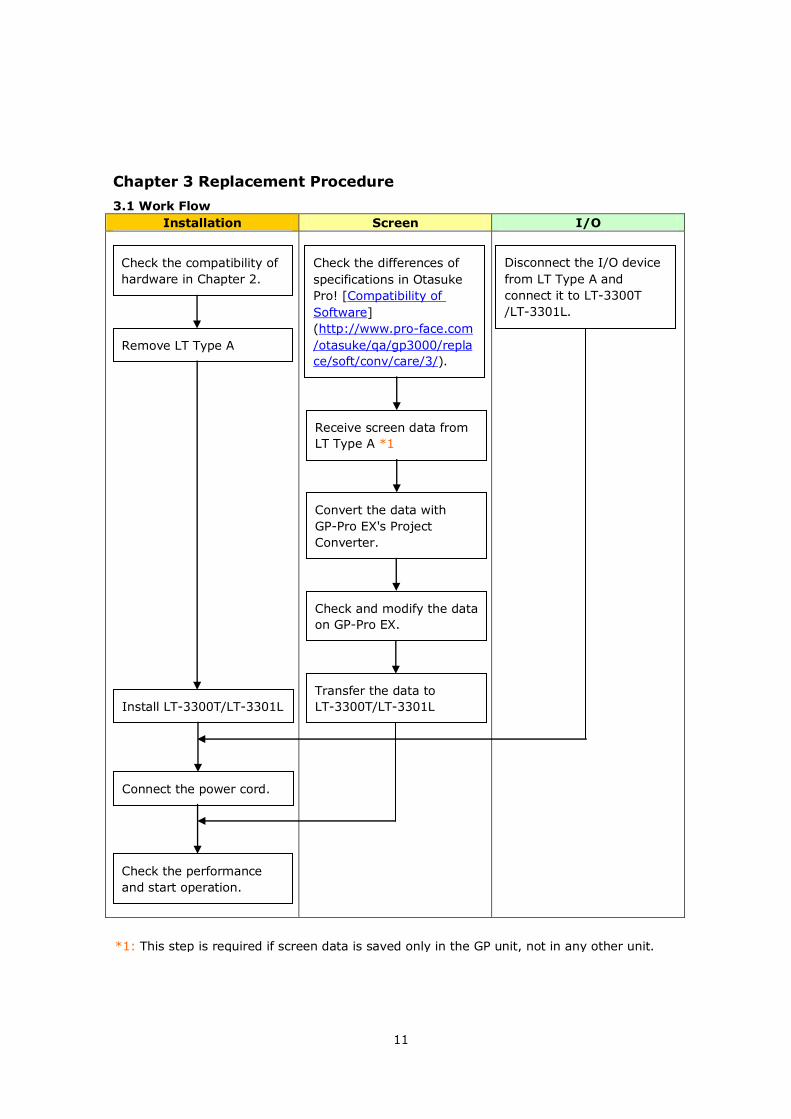
3.1 Work Flow
Installation Screen I/O
Check the compatibility of
hardware in Chapter 2.
Check the differences of
specifications in Otasuke
Pro! [Compatibility of
Software]
(http://www.pro-face.com
/otasuke/qa/gp3000/repla
ce/soft/conv/care/3/).
Disconnect the I/O device
from LT Type A and
connect it to LT-3300T
/LT-3301L.
Remove LT Type A
Receive screen data from
LT Type A *1
Install LT-3300T/LT-3301L
Connect the power cord.
Check the performance
and start operation.
Convert the data with
GP-Pro EX's Project
Converter.
Check and modify the data
on GP-Pro EX.
Transfer the data to
LT-3300T/LT-3301L
*1: This step is required if screen data is saved only in the GP unit, not in any other unit.
12
3.2 Preparation
Requirements for
receiving screen data
from LT Type A *1
PC in which GP-PRO/PBIII for Windows C-Package03 V7.0 or later
is installed *2
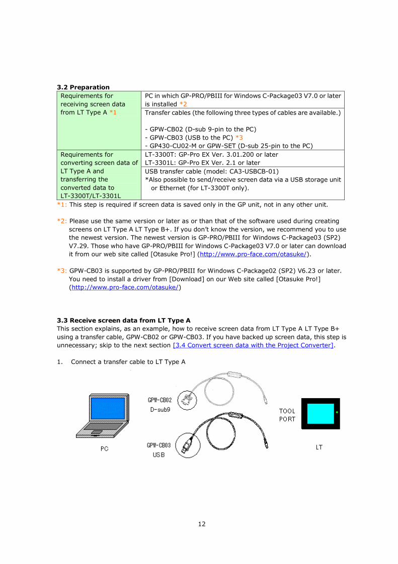
Transfer cables (the following three types of cables are available.)
- GPW-CB02 (D-sub 9-pin to the PC)
- GPW-CB03 (USB to the PC) *3
- GP430-CU02-M or GPW-SET (D-sub 25-pin to the PC)
Requirements for
converting screen data of
LT Type A and
transferring the
converted data to
LT-3300T/LT-3301L
LT-3300T: GP-Pro EX Ver. 3.01.200 or later
LT-3301L: GP-Pro EX Ver. 2.1 or later
USB transfer cable (model: CA3-USBCB-01)
*Also possible to send/receive screen data via a USB storage unit
or Ethernet (for LT-3300T only).
*1: This step is required if screen data is saved only in the GP unit, not in any other unit.
*2: Please use the same version or later as or than that of the software used during creating
screens on LT Type A LT Type B+. If you don’t know the version, we recommend you to use
the newest version. The newest version is GP-PRO/PBIII for Windows C-Package03 (SP2)
V7.29. Those who have GP-PRO/PBIII for Windows C-Package03 V7.0 or later can download
it from our web site called [Otasuke Pro!] (http://www.pro-face.com/otasuke/).
*3: GPW-CB03 is supported by GP-PRO/PBIII for Windows C-Package02 (SP2) V6.23 or later.
You need to install a driver from [Download] on our Web site called [Otasuke Pro!]
(http://www.pro-face.com/otasuke/)
3.3 Receive screen data from LT Type A
This section explains, as an example, how to receive screen data from LT Type A LT Type B+
using a transfer cable, GPW-CB02 or GPW-CB03. If you have backed up screen data, this step is
unnecessary; skip to the next section [3.4 Convert screen data with the Project Converter].
1. Connect a transfer cable to LT Type A
13
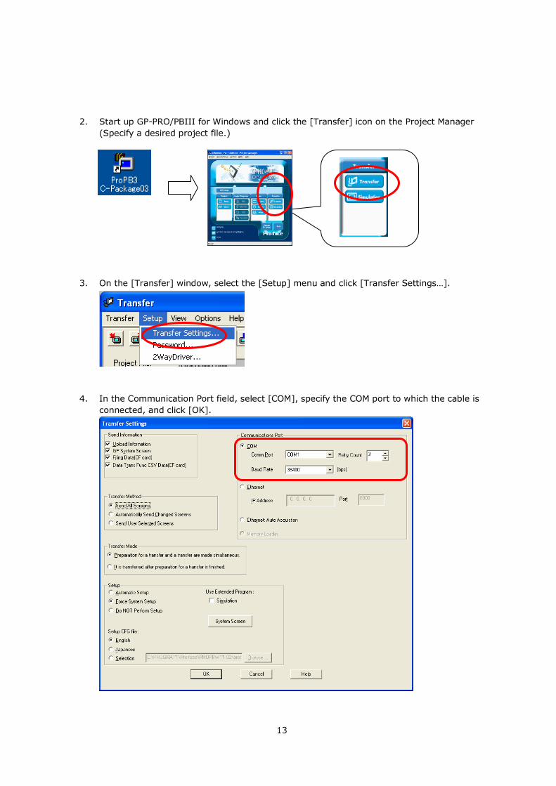
2. Start up GP-PRO/PBIII for Windows and click the [Transfer] icon on the Project Manager
(Specify a desired project file.)
3. On the [Transfer] window, select the [Setup] menu and click [Transfer Settings…].
4. In the Communication Port field, select [COM], specify the COM port to which the cable is
connected, and click [OK].
14
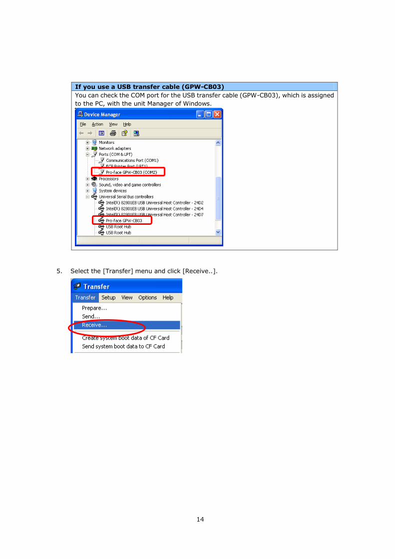
If you use a USB transfer cable (GPW-CB03)
You can check the COM port for the USB transfer cable (GPW-CB03), which is assigned
to the PC, with the unit Manager of Windows.
5. Select the [Transfer] menu and click [Receive..].
15
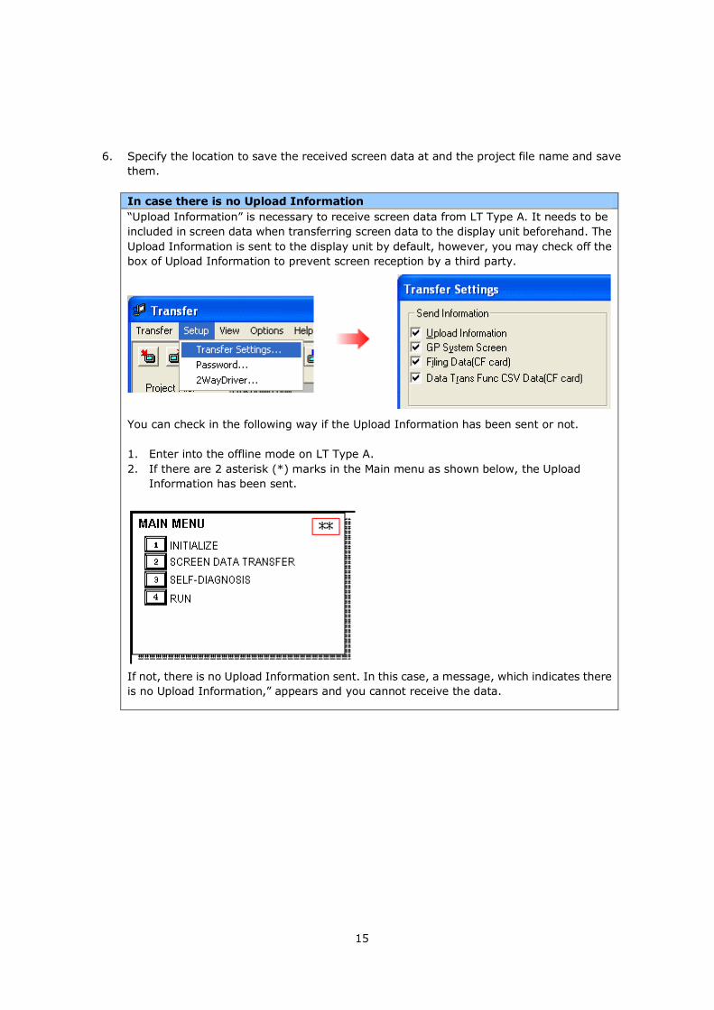
6. Specify the location to save the received screen data at and the project file name and save
them.
In case there is no Upload Information
“Upload Information” is necessary to receive screen data from LT Type A. It needs to be
included in screen data when transferring screen data to the display unit beforehand. The
Upload Information is sent to the display unit by default, however, you may check off the
box of Upload Information to prevent screen reception by a third party.
You can check in the following way if the Upload Information has been sent or not.
1. Enter into the offline mode on LT Type A.
2. If there are 2 asterisk (*) marks in the Main menu as shown below, the Upload
Information has been sent.
If not, there is no Upload Information sent. In this case, a message, which indicates there
is no Upload Information,” appears and you cannot receive the data.
16
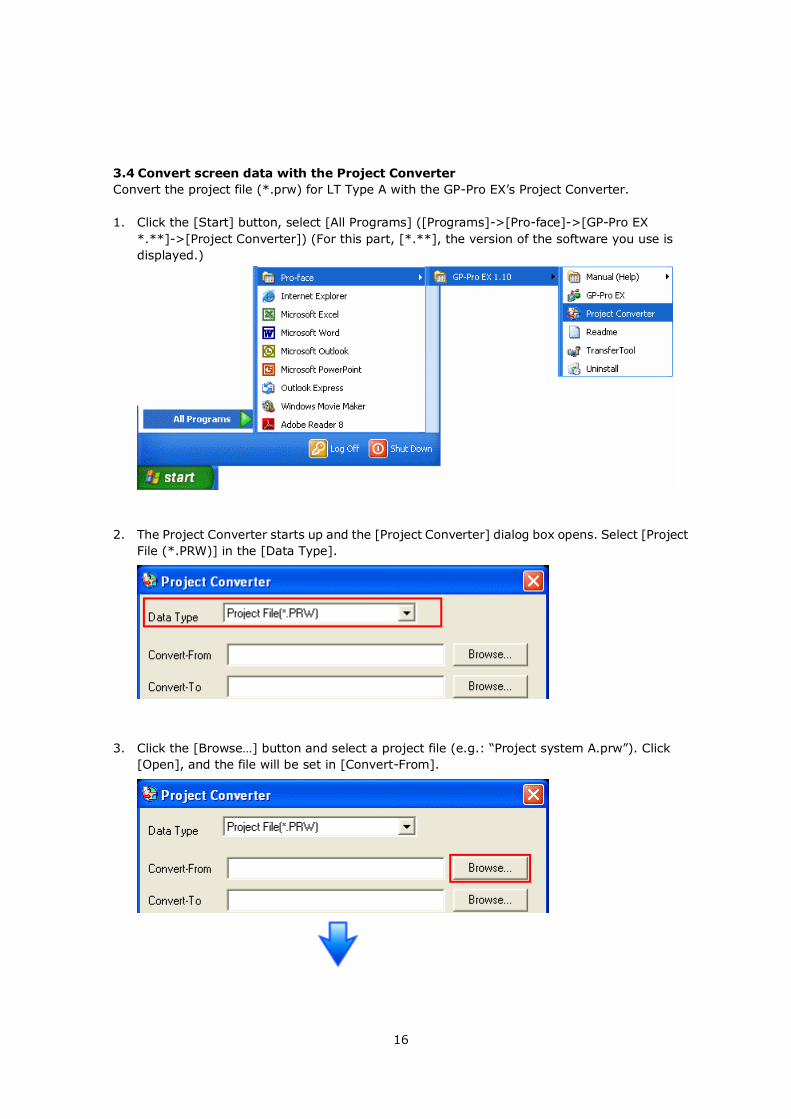
3.4 Convert screen data with the Project Converter
Convert the project file (*.prw) for LT Type A with the GP-Pro EX’s Project Converter.
1. Click the [Start] button, select [All Programs] ([Programs]->[Pro-face]->[GP-Pro EX
*.**]->[Project Converter]) (For this part, [*.**], the version of the software you use is
displayed.)
2. The Project Converter starts up and the [Project Converter] dialog box opens. Select [Project
File (*.PRW)] in the [Data Type].
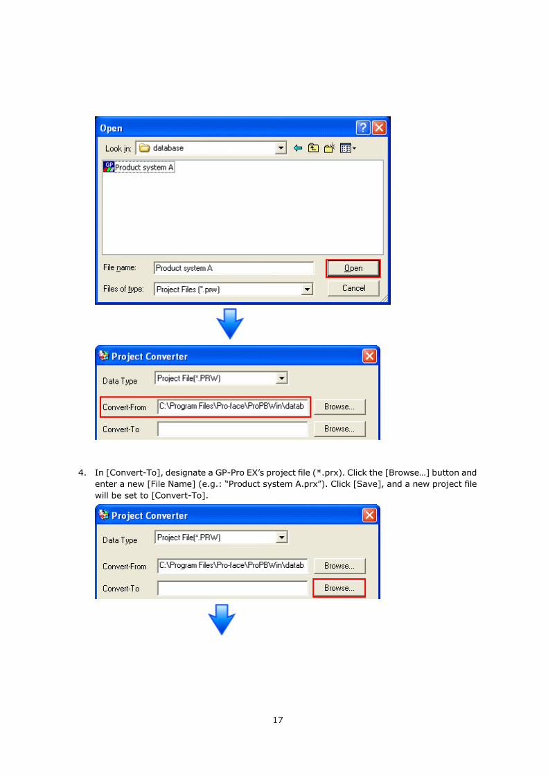
3. Click the [Browse…] button and select a project file (e.g.: “Project system A.prw”). Click
[Open], and the file will be set in [Convert-From].
17
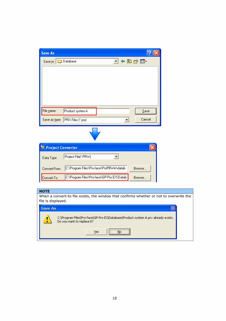
4. In [Convert-To], designate a GP-Pro EX’s project file (*.prx). Click the [Browse…] button and
enter a new [File Name] (e.g.: “Product system A.prx”). Click [Save], and a new project file
will be set to [Convert-To].
18
NOTE
When a convert-to file exists, the window that confirms whether or not to overwrite the
file is displayed.
19
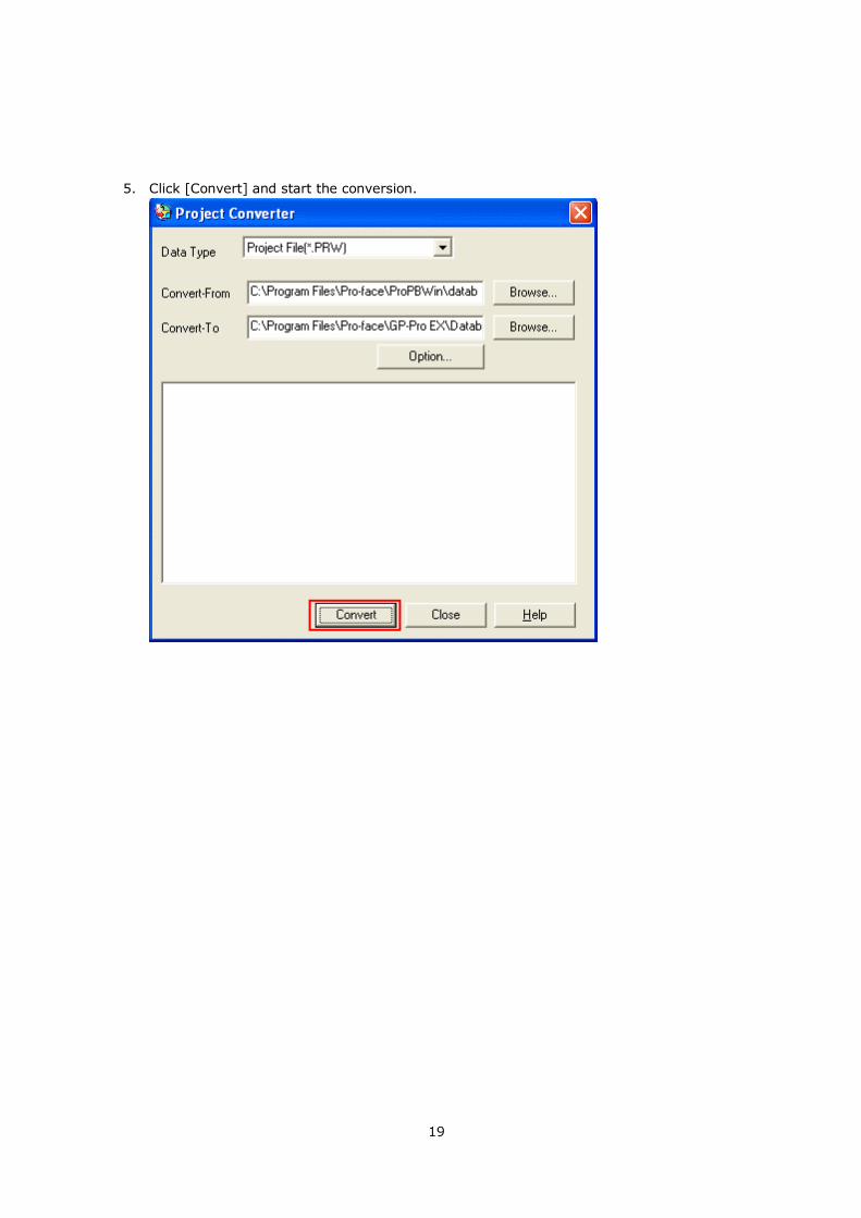
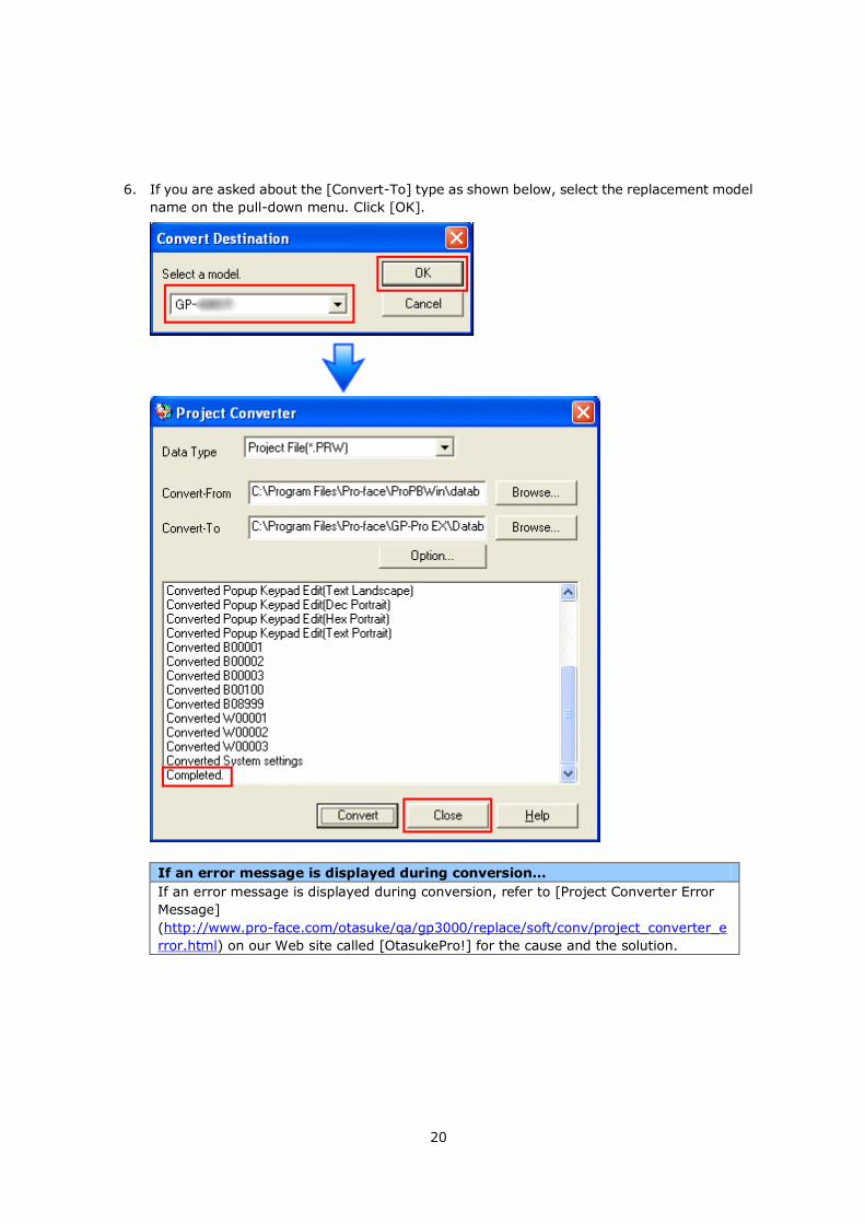
5. Click [Convert] and start the conversion.
20
6. If you are asked about the [Convert-To] type as shown below, select the replacement model
name on the pull-down menu. Click [OK].
If an error message is displayed during conversion…
If an error message is displayed during conversion, refer to [Project Converter Error
Message]
(http://www.pro-face.com/otasuke/qa/gp3000/replace/soft/conv/project_converter_e
rror.html) on our Web site called [OtasukePro!] for the cause and the solution.
21
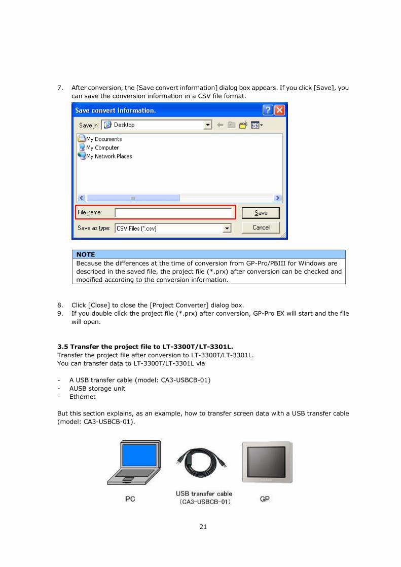
7. After conversion, the [Save convert information] dialog box appears. If you click [Save], you
can save the conversion information in a CSV file format.
NOTE
Because the differences at the time of conversion from GP-Pro/PBIII for Windows are
described in the saved file, the project file (*.prx) after conversion can be checked and
modified according to the conversion information.
8. Click [Close] to close the [Project Converter] dialog box.
9. If you double click the project file (*.prx) after conversion, GP-Pro EX will start and the file
will open.
3.5 Transfer the project file to LT-3300T/LT-3301L.
Transfer the project file after conversion to LT-3300T/LT-3301L.
You can transfer data to LT-3300T/LT-3301L via
- A USB transfer cable (model: CA3-USBCB-01)
- AUSB storage unit
- Ethernet
But this section explains, as an example, how to transfer screen data with a USB transfer cable
(model: CA3-USBCB-01).
22
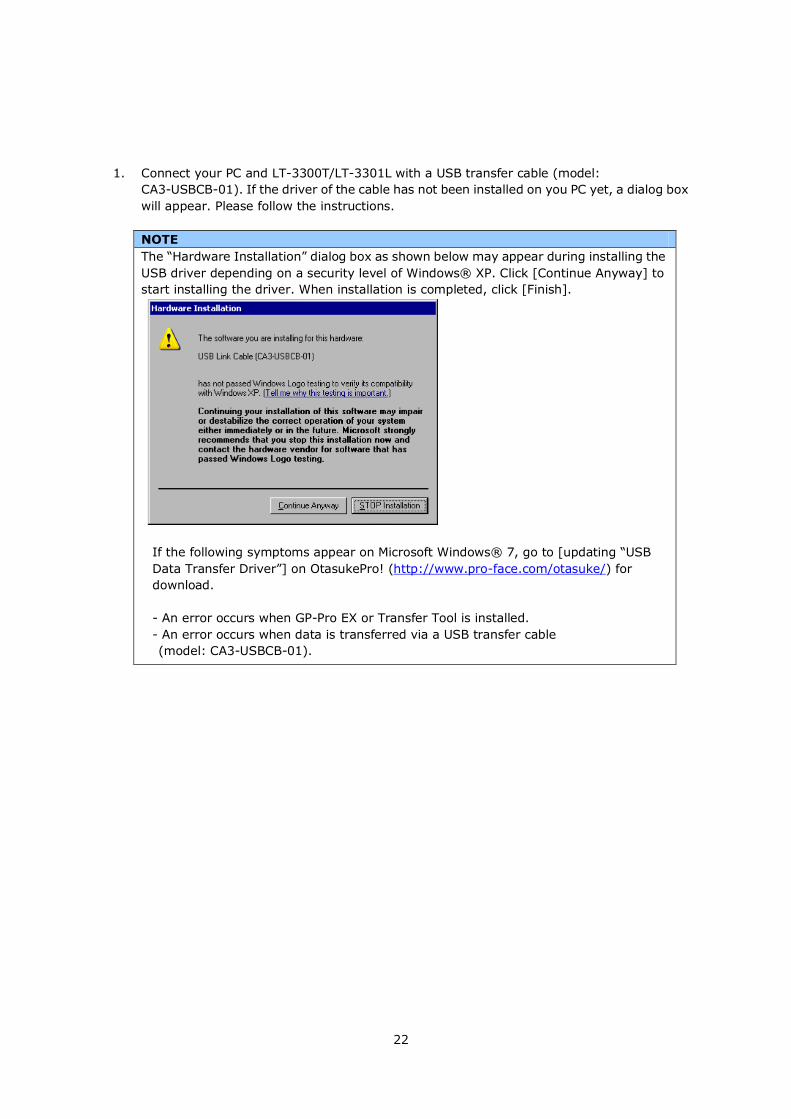
1. Connect your PC and LT-3300T/LT-3301L with a USB transfer cable (model:
CA3-USBCB-01). If the driver of the cable has not been installed on you PC yet, a dialog box
will appear. Please follow the instructions.
NOTE
The “Hardware Installation” dialog box as shown below may appear during installing the
USB driver depending on a security level of Windows® XP. Click [Continue Anyway] to
start installing the driver. When installation is completed, click [Finish].
If the following symptoms appear on Microsoft Windows® 7, go to [updating “USB
Data Transfer Driver”] on OtasukePro! (http://www.pro-face.com/otasuke/) for
download.
- An error occurs when GP-Pro EX or Transfer Tool is installed.
- An error occurs when data is transferred via a USB transfer cable
(model: CA3-USBCB-01).
23
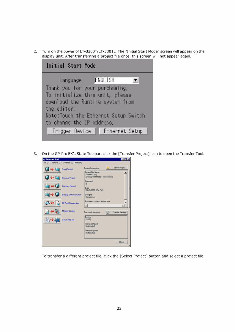
2. Turn on the power of LT-3300T/LT-3301L. The “Initial Start Mode” screen will appear on the
display unit. After transferring a project file once, this screen will not appear again.
3. On the GP-Pro EX’s State Toolbar, click the [Transfer Project] icon to open the Transfer Tool.
To transfer a different project file, click the [Select Project] button and select a project file.
24
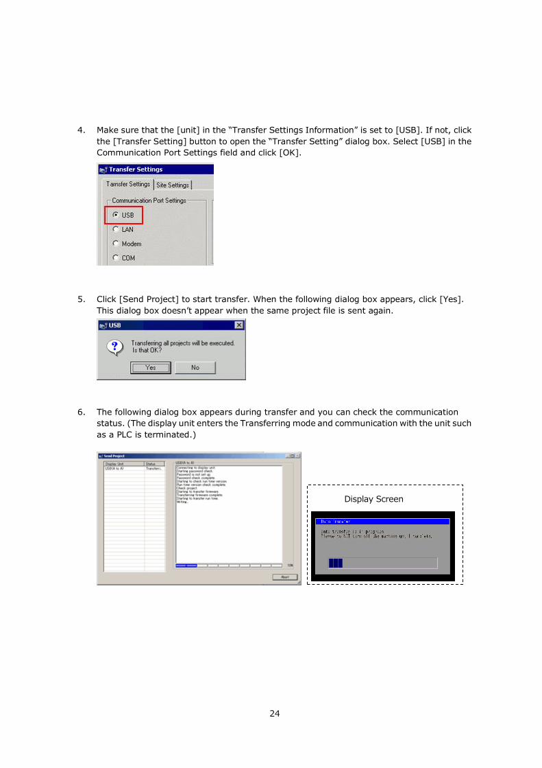
4. Make sure that the [unit] in the “Transfer Settings Information” is set to [USB]. If not, click
the [Transfer Setting] button to open the “Transfer Setting” dialog box. Select [USB] in the
Communication Port Settings field and click [OK].
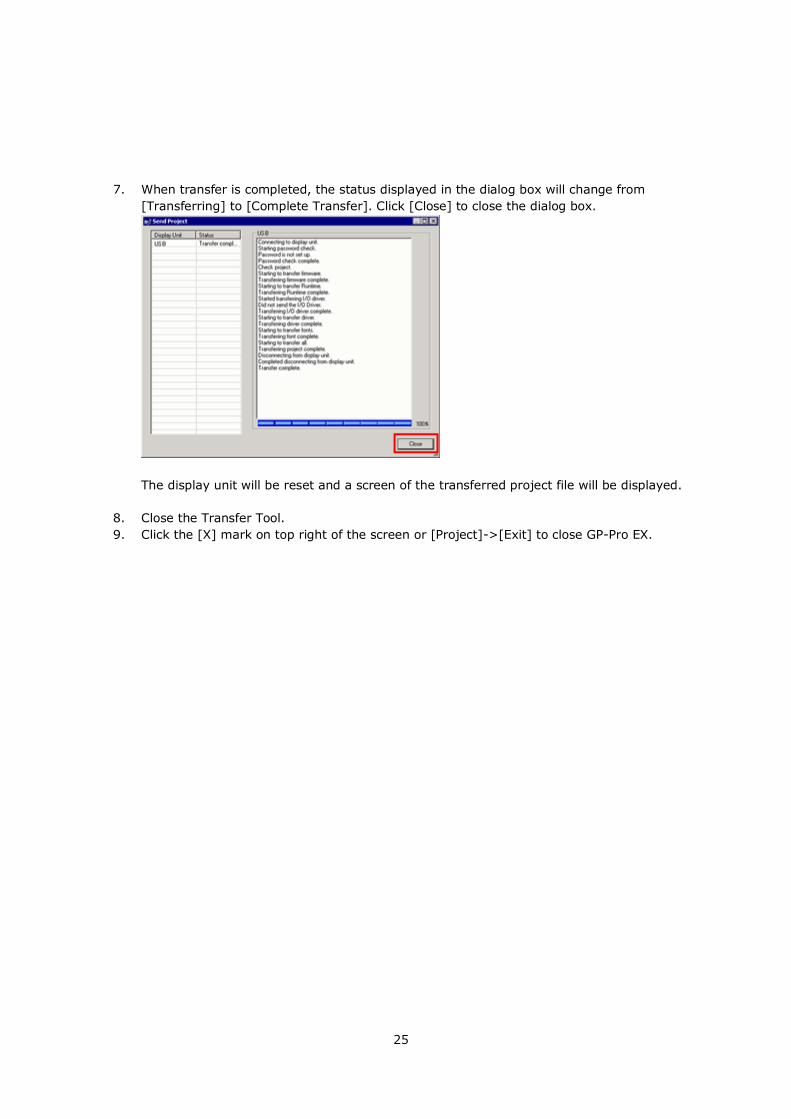
5. Click [Send Project] to start transfer. When the following dialog box appears, click [Yes].
This dialog box doesn’t appear when the same project file is sent again.
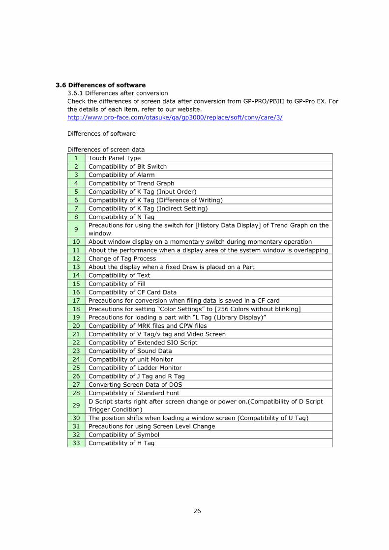
6. The following dialog box appears during transfer and you can check the communication
status. (The display unit enters the Transferring mode and communication with the unit such
as a PLC is terminated.)
Display Screen
Display Screen
25
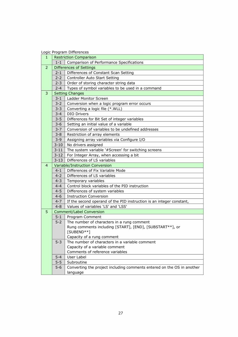
7. When transfer is completed, the status displayed in the dialog box will change from
[Transferring] to [Complete Transfer]. Click [Close] to close the dialog box.
The display unit will be reset and a screen of the transferred project file will be displayed.
8. Close the Transfer Tool.
9. Click the [X] mark on top right of the screen or [Project]->[Exit] to close GP-Pro EX.
26
3.6 Differences of software
3.6.1 Differences after conversion
Check the differences of screen data after conversion from GP-PRO/PBIII to GP-Pro EX. For
the details of each item, refer to our website.
http://www.pro-face.com/otasuke/qa/gp3000/replace/soft/conv/care/3/
Differences of software
Differences of screen data
1 Touch Panel Type
2 Compatibility of Bit Switch
3 Compatibility of Alarm
4 Compatibility of Trend Graph
5 Compatibility of K Tag (Input Order)
6 Compatibility of K Tag (Difference of Writing)
7 Compatibility of K Tag (Indirect Setting)
8 Compatibility of N Tag
9 Precautions for using the switch for [History Data Display] of Trend Graph on the
window
10 About window display on a momentary switch during momentary operation
11 About the performance when a display area of the system window is overlapping
12 Change of Tag Process
13 About the display when a fixed Draw is placed on a Part
14 Compatibility of Text
15 Compatibility of Fill
16 Compatibility of CF Card Data
17 Precautions for conversion when filing data is saved in a CF card
18 Precautions for setting “Color Settings” to [256 Colors without blinking]
19 Precautions for loading a part with “L Tag (Library Display)”
20 Compatibility of MRK files and CPW files
21 Compatibility of V Tag/v tag and Video Screen
22 Compatibility of Extended SIO Script
23 Compatibility of Sound Data
24 Compatibility of unit Monitor
25 Compatibility of Ladder Monitor
26 Compatibility of J Tag and R Tag
27 Converting Screen Data of DOS
28 Compatibility of Standard Font
29 D Script starts right after screen change or power on.(Compatibility of D Script
Trigger Condition)
30 The position shifts when loading a window screen (Compatibility of U Tag)
31 Precautions for using Screen Level Change
32 Compatibility of Symbol
33 Compatibility of H Tag
27
Logic Program Differences
1 Restriction Comparison
1-1 Comparison of Performance Specifications
2 Differences of Settings
2-1 Differences of Constant Scan Setting
2-2 Controller Auto Start Setting
2-3 Order of storing character string data
2-4 Types of symbol variables to be used in a command
3 Setting Changes
3-1 Ladder Monitor Screen
3-2 Conversion when a logic program error occurs
3-3 Converting a logic file (*.WLL)
3-4 DIO Drivers
3-5 Differences for Bit Set of integer variables
3-6 Setting an initial value of a variable
3-7 Conversion of variables to be undefined addresses
3-8 Restriction of array elements
3-9 Assigning array variables via Configure I/O
3-10 No drivers assigned
3-11 The system variable '#Screen' for switching screens
3-12 For Integer Array, when accessing a bit
3-13 Differences of LS variables
4 Variable/Instruction Conversion
4-1 Differences of Fix Variable Mode
4-2 Differences of LS variables
4-3 Temporary variables
4-4 Control block variables of the PID instruction
4-5 Differences of system variables
4-6 Instruction Conversion
4-7 If the second operand of the PID instruction is an integer constant,
4-8 Values of variables 'LS' and 'LSS'
5 Comment/Label Conversion
5-1 Program Comment
5-2 The number of characters in a rung comment
Rung comments including [START], [END], [SUBSTART**], or
[SUBEND**]
Capacity of a rung comment
5-3 The number of characters in a variable comment
Capacity of a variable comment
Comments of reference variables
5-4 User Label
5-5 Subroutine
5-6 Converting the project including comments entered on the OS in another
language