Embed Size (px)
Citation preview

74-07579-000-A 2/96 © 1996 Radionics, Inc.
R A D I O N I C S
EasikeyEasikey 1000 / 1000 PlusInstallation and Programming Manual

74-07579-000-A 2/96 Page i © 1996 Radionics, Inc.
Notices
NoticeThe material and instructions in this manual have been carefully checked foraccuracy and are presumed to be reliable. However, Radionics, Inc. assumes noresponsibility for inaccuracies and reserves the right to modify and revise thismanual without notice.
It is our goal at Radionics to always supply accurate and reliable documentation.If a discrepancy is found in this documentation, please mail a photocopy of thecorrected material to:
Radionics, Inc.Technical Writing Department1800 Abbott StreetSalinas, California 93901
WarrantyThis product is covered under the five-year limited warranty described inRadionics “Standard Terms and Conditions” in the Radionics Product Catalog(L100).
FCC NoticeThis equipment has been tested and found to comply with the limits for a Class Bdigital device, pursuant to part 15 of the FCC Rules. These limits are designed toprovide reasonable protection against harmful interference in a residentialinstallation. This equipment generates, uses and can radiate radio frequencyenergy and, if not installed and used in accordance with the instructions, maycause harmful interference to radio communications. However, there is noguarantee that interference will not occur in a particular installation. If thisequipment does cause harmful interference to radio or television reception, whichcan be determined by turning the equipment off and on, the user is encouragedto try to correct the interference by one or more of the following measures:
1) Reorient or relocate the receiving antenna
2) Increase the separation between the equipment and receiver.
3) Connect the equipment into an outlet on a circuit different from that to whichthe receiver is connected.
4) Consult the dealer or an experienced radio/TV technician for help.

74-07579-000-A 2/96 Page ii © 1996 Radionics, Inc.
Table of Contents
NOTICES .............................................................................................................................................................I
NOTICE................................ ................................ ................................ ................................ ............................... IWARRANTY ................................ ................................ ................................ ................................ ........................ IFCC NOTICE ................................ ................................ ................................ ................................ ...................... I
TABLE OF CONTENTS................................................................................................................................... II
THE EASIKEY 1000/1000 PLUS...................................................................................................................... 1
OVERVIEW................................ ................................ ................................ ................................ ......................... 1SYSTEM FEATURES................................ ................................ ................................ ................................ ............. 1
Access Points ............................................................................................................................................... 1Lock Outputs................................................................................................................................................ 1Personnel..................................................................................................................................................... 1Time Profiles................................................................................................................................................ 1Door Monitoring Alarms (Easikey 1000 Plus Only).................................................................................... 2Printer Facilities.......................................................................................................................................... 2
SYSTEM OPERATION................................ ................................ ................................ ................................ ........... 2
INSTALLING THE SYSTEM........................................................................................................................... 3
EASIKEY 1000/1000 PLUS ................................ ................................ ................................ ................................ . 3CHOOSING THE BEST LOCATION FOR THE EK1000 ................................ ................................ .............................. 4INSTALLING THE POWER SUPPLY ................................ ................................ ................................ ........................ 4
Choosing the Stand-by Battery and Low Battery Indicator ......................................................................... 4INSTALLING AN OPTIONAL PRINTER ................................ ................................ ................................ .................... 5
Printer Specifications .................................................................................................................................. 5Printer Cable ............................................................................................................................................... 6
USING EXTERNAL READERS FOR SYSTEM ADMINISTRATION................................ ................................ ................ 6Connecting External Readers ...................................................................................................................... 6Using Wiegand Device Readers................................................................................................................... 7
INSTALLING READERS AND CONNECTING LOCK OUTPUTS................................ ................................ .................... 7Readers ........................................................................................................................................................ 7Wiring Considerations for All Readers........................................................................................................ 7Reader Connections..................................................................................................................................... 7Wiegand Reader Wiring .............................................................................................................................. 8
MOUNTING THE READER ................................ ................................ ................................ ................................ .... 9Request to Exit ............................................................................................................................................. 9
ALARM EVENT MONITORING (EASIKEY 1000 PLUS ONLY)................................ ................................ .................. 9DOOR CONTACT MONITORING (EASIKEY 1000 PLUS ONLY)................................ ................................ .............. 10
Connecting the Door Contact .................................................................................................................... 10READER TAMPER DETECTION (EASIKEY 1000 PLUS ONLY) ................................ ................................ ............... 10
Lock Outputs.............................................................................................................................................. 10Fire Escape Safety ..................................................................................................................................... 11
ALARM OUTPUT RELAY (EASIKEY 1000 PLUS ONLY) ................................ ................................ ....................... 11FREE EXIT AND EMERGENCY OVERRIDE OPTION ................................ ................................ ............................... 12
OPERATING THE SYSTEM.......................................................................................................................... 13
OVERVIEW OF SYSTEM ADMINISTRATION ................................ ................................ ................................ ......... 13

74-07579-000-A 2/96 Page iii © 1996 Radionics, Inc.
Using the Editor Key/Cards....................................................................................................................... 13Master Editor Key/Card ......................................................................................................................................... 13Sub Editor Key/Cards............................................................................................................................................. 13Editor Time-out...................................................................................................................................................... 13
HOW TO USE THE EK1000 KEYPAD AND EDITOR MODE ................................ ................................ ................... 14USING THE KEYPAD ................................ ................................ ................................ ................................ ......... 14
Entering Data ............................................................................................................................................ 14SYSTEM DISPLAYS AND ALARMS................................ ................................ ................................ ...................... 15
Power Indicators ....................................................................................................................................... 15Normal Displays ........................................................................................................................................ 15
DOOR LEFT OPEN WARNING (EASIKEY 1000 PLUS ONLY) ................................ ................................ ................ 16Unauthorized Access Alarm (Easikey 1000 Plus Only) ............................................................................. 16Cable or Reader Tamper Alarm (Easikey 1000 Plus Only) ....................................................................... 17Alarm Relay Response (Easikey 1000 Plus Only) ...................................................................................... 17
PROGRAMMING THE SYSTEM.................................................................................................................. 18
APPLYING POWER ................................ ................................ ................................ ................................ ............ 18Installing the Master Editor Key/Card ...................................................................................................... 18Testing the Master Editor Key/Card and System....................................................................................... 19
INSTALLING AND VOIDING ADDITIONAL SUB EDITOR KEY/CARDS................................ ................................ ..... 20Adding a Sub Editor Key/Card .................................................................................................................. 20Voiding an Sub Editor Key/Card............................................................................................................... 21Setting the Clock........................................................................................................................................ 22
TIME PROFILES AND TIME PERIODS................................ ................................ ................................ ................... 23Overview of Time Profiles.......................................................................................................................... 23Time Profiles for Doors ............................................................................................................................. 23Time Profiles for User Keys....................................................................................................................... 23When Time Profiles Actually Begin and End ............................................................................................. 23Time periods Do Not Cross Midnight........................................................................................................ 2324-Hour Operation .................................................................................................................................... 24Programming and Editing Time Profiles................................................................................................... 24
PROGRAMMING THE DOOR DATA................................ ................................ ................................ ...................... 28Lock Release Time ..................................................................................................................................... 28Door Open Time (Easikey 1000 Plus Systems Only) ................................................................................. 28Door Time Profile...................................................................................................................................... 28Door Options ............................................................................................................................................. 28
1 Lock Mode .......................................................................................................................................................... 282 Free Exit/Emergency Override ............................................................................................................................ 293 RTE Report ......................................................................................................................................................... 294 Not Used - Leave UNSET................................................................................................................................... 295 Set/Reset ............................................................................................................................................................. 29
USING THE DOORS FUNCTION................................ ................................ ................................ ........................... 30Channel Interlock ...................................................................................................................................... 31Programming Channel Interlock ............................................................................................................... 31Anti-Passback ............................................................................................................................................ 31Programming Anit-Passback ..................................................................................................................... 32
MANUAL LOCK/UNLOCK FOR CONTROLLING THE DOORS ................................ ................................ .................. 32Doors controlled by a Time Profile ........................................................................................................... 32Doors not controlled by a Time Profile ..................................................................................................... 32To Lock/Unlock a Door ............................................................................................................................. 33
ACCESS LEVELS & TIME PROFILES ................................ ................................ ................................ ................... 33Access Levels ............................................................................................................................................. 33

74-07579-000-A 2/96 Page iv © 1996 Radionics, Inc.
USER (KEY/CARD) NUMBERS................................ ................................ ................................ ........................... 34ADDING OR EDITING USERS................................ ................................ ................................ .............................. 34
Adding Several Keys .................................................................................................................................. 36Editing a Key/Card.................................................................................................................................... 36Displaying a Key/Card PIN Number ........................................................................................................ 37Identifying a Key/Card .............................................................................................................................. 38Voiding Key/Cards (Users) from the EK1000 ........................................................................................... 38
ADDITIONAL SYSTEM OPTIONS................................ ................................ ................................ ......................... 39Software Version Display .......................................................................................................................... 39Upload/Download Option ......................................................................................................................... 40Display Last Five Keys or Cards Used...................................................................................................... 41
TRANSACTION LOGGING................................ ................................ ................................ ................................ ... 41Sample transaction printout ...................................................................................................................... 41
TRANSACTION EVENT DEFINITIONS ................................ ................................ ................................ .................. 42Normal Entry and Exit............................................................................................................................... 42Alarms and Warnings ................................................................................................................................ 42No Access................................................................................................................................................... 43Door Events ............................................................................................................................................... 43Other Events .............................................................................................................................................. 43
PRINTING REPORTS ................................ ................................ ................................ ................................ .......... 44User Selected Reports................................................................................................................................ 44To Print the Database................................................................................................................................ 44
Sample database printout ........................................................................................................................................ 45Printing Selected Key/card Transactions .................................................................................................. 46Clearing the Transaction Database........................................................................................................... 46
GLOSSARY ...................................................................................................................................................... 47
SPECIFICATIONS........................................................................................................................................... 49
POWER INPUT ................................ ................................ ................................ ................................ .................. 49POWER OUTPUT ................................ ................................ ................................ ................................ ............... 49ENVIRONMENTAL................................ ................................ ................................ ................................ ............. 49DOORS................................ ................................ ................................ ................................ ............................. 49USERS ................................ ................................ ................................ ................................ ............................. 49TRANSACTION BUFFER................................ ................................ ................................ ................................ ..... 49PRINTER OUTPUT ................................ ................................ ................................ ................................ ............. 49TIME PROFILES ................................ ................................ ................................ ................................ ................ 49ENCLOSURES ................................ ................................ ................................ ................................ ................... 49EK1000 PLUS ................................ ................................ ................................ ................................ ................. 49
NOTES............................................................................................................................................................... 50

74-07579-000-A 2/96 Page 1 © 1996 Radionics, Inc.
THE EASIKEY 1000/1000 PLUS
OverviewThe Easikey 1000 is a two door access control system using Radionics'Easikey/Readykey proximity key/card technology. The complete system includesa EK1000 with a numeric keypad and display, one or two readers located at thecontrolled doors and a number of Easikey electronic keys or cards. See theRadionics Product Catalog (L100) for a list of components and accessoriessuitable for use with the Radionics Easikey 1000.
System Features
Access PointsThe Easikey 1000 controls one or two doors, each of which may be up to300ft/100m away from the controller. You may install the following types ofreaders with the EK1000. See Radionics Product Catalog (L100) for a list ofcomponents and accessories suitable for use with the Radionics Easikey 1000.
Easikey proximity readersReadykey proximity readersReadykey PIN readersWiegand 26-bit reader with an Easikey EK12 Wiegand Interface
The EK1000 also provides an input for Request to Exit switches, allowing usersto exit through a lock-controlled door from the secured side.
Lock OutputsThe Easikey 1000 door controller supplies 12 VDC at 1 Amp current for poweringeither fail-safe (power to lock) or fail-secure (power to unlock) locks.
PersonnelThe EK1000 can store up to 1000 individual users in its memory. The systemadministrator can cause the EK1000 to allow each key/card to enter through bothdoors, either door, or neither door. The system administrator can assign eachuser a Time Profile to restrict access to certain days and times.
Time ProfilesThe system administrator can create up to eight Time Profiles; each containingup to three Time Periods. The administrator can assign Time Profiles to doorsand users. For example, the administrator can program the door to openbetween 9:00 a.m. and 5:00 p.m., Monday through Friday, but require users topresent a key/card all other days and times. Similarly, the administrator canassign a Time Profile to a user's key/card that only allows the user to use thekey/card on certain days and at certain times.

74-07579-000-A 2/96 Page 2 © 1996 Radionics, Inc.
Door Monitoring Alarms (Easikey 1000 Plus Only)Easikey 1000 Plus systems can monitor door contact switches. This enablesEasikey 1000 Plus systems to generate the following types of alarms:
Unauthorized Access AlarmsThe EK1000 creates this alarm when someone opens a door without using a validkey/card, or without activating the Request to Exit device.Door Left Open WarningsThe EK1000 creates this condition when something causes the door to stay openlonger than the time programmed in the Door Open Time option.
Printer FacilitiesThe Easikey 1000 has a built-in printer interface. If you connect a printer to theEK1000, the system can print each event as it happens, or store up to 1000events for printing on demand. The system can print database informationincluding users, Time Profiles and door information, and the movements ofindividual users in selected reports.
System OperationThis manual describes installations using proximity key/cards: The informationprovided in this manual assumes that you are using Radionics' Easikey orReadykey proximity keys or cards with the system.
The system operates when a user presents an Easikey key/card close to anEasikey door reader. The key or card transfers its unique serial number to thereader. The reader transfers the key's or card’s serial number to the EK1000door controller. When the EK1000 receives the serial number, it checks thefollowing items before allowing access to the secured area:
1. Is the key/card's serial number one that has been stored into the EK1000'sdatabase?
2. Is the user assigned to this key/card allowed through this door?3. Is the user assigned to this key/card allowed to enter through this door at this
time and on this day?
If the answer to all three questions is “Yes”, the EK1000 will enable its lockoutput used to activate an electric locking mechanism for a programmed numberof seconds, allowing the key/card holder to pass through the door.
Installers often place a button or switch on the secure side of the door called theRequest to Exit switch. The Request to Exit switch allows anyone to leave thesecured area without using their key/card. This is also sometimes referred to asan “Egress” input.
74-07579-000-A 2/96 Page 3 © 1996 Radionics, Inc.
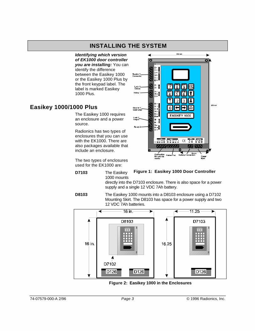
INSTALLING THE SYSTEMIdentifying which versionof EK1000 door controlleryou are installing: You canidentify the differencebetween the Easikey 1000or the Easikey 1000 Plus bythe front keypad label. Thelabel is marked Easikey1000 Plus.
Easikey 1000/1000 PlusThe Easikey 1000 requiresan enclosure and a powersource.
Radionics has two types ofenclosures that you can usewith the EK1000. There arealso packages available thatinclude an enclosure.
The two types of enclosuresused for the EK1000 are:
D7103 The Easikey1000 mountsdirectly into the D7103 enclosure. There is also space for a powersupply and a single 12 VDC 7Ah battery.
D8103 The Easikey 1000 mounts into a D8103 enclosure using a D7102Mounting Skirt. The D8103 has space for a power supply and two12 VDC 7Ah batteries.
Figure 2: Easikey 1000 in the Enclosures
Figure 1: Easikey 1000 Door Controller

74-07579-000-A 2/96 Page 4 © 1996 Radionics, Inc.
Choosing the Best Location for the EK1000Mount the controller in a secure but accessible location. System administratorswill program the system at the EK1000, so proper mounting of the EK1000 doorcontroller will allow the display to be easily viewed by the system administrators.
Installing the Power SupplyThe Easikey 1000 requires one of the three types of power sources shownbelow:
A 12 VDC 3 Amp power supply.
A 24 VDC 1.5 Amp power supply.
A 16.5V AC power source at a minimum 40VA rating. Radionics offers theD1640 transformer that supplies 16.5 VAC @ 40VA.
AC Power LED OFF in Editor Mode: When the AC power supply is providingpower to the controller, the red LED on the controller illuminates, except whenthe controller is in the Editor's Mode. If you are using a 12 VDC power source thered LED will not illuminate even though power is supplied to the EK1000.
The EK1000 door controller and two Easikey readers require 600mA. In addition,the power supply must provide power for locks you attach to the EK1000. Eachlock output can supply up to 1 Amp continuously at 12 VDC. Therefore, choose apower supply capable of providing between 2.6 Amps and 3 Amps total,depending on the currentconsumption of the locks.
The database is preserved whenpower is completely lost: Thecontroller stores the database inbattery-backed memory. If AC andbattery power are both disconnectedfrom the EK1000, the EK1000preserves the information in thedatabase. The database is preservedfor up to 12 months when the EK1000is not powered. An internal NICADbattery is charged as long as theEK1000 is powered. If the NICADbattery discharges during a powerfailure, it recharges when power returns to the EK1000. Installers or userscannot replace the internal NICAD battery. The NICAD battery must be replacedat the factory.
Figure 3 shows where to connect the power source being used to the EK1000door controller.
Choosing the Stand-by Battery and Low Battery IndicatorBefore choosing the battery to the power supply, calculate the battery's capacityrequirement based on:
The current consumption of the EK1000 and Easikey readers (up to 600mA).The current consumption of the locks when operating normally (up to 1 Amp
Figure 3: Connecting the powersource and battery to the EK1000

74-07579-000-A 2/96 Page 5 © 1996 Radionics, Inc.
each).The type of lock (fail-safe or fail-secure).The length of time the system should operate without AC power to the EK1000 orpower supply.
Example: An Easikey 1000 with two Easikey readers and two 300mA fail-safelocks will continuously draw about 1.2 Amps. Using a 7Ah battery (one D126) willprovide approximately 5.9 hours standby time. A 14Ah battery (two D126s)provides approximately 16.5 hours standby time.
After determining the standby requirement for the battery, place the batteries onthe bottom of the enclosure and connect them to the battery terminals (seeFigure 3).
Battery LED OFF in Editor Mode: When battery power falls below 12 VDC, thegreen LED on the EK1000 illuminates. The green LED extinguishes when thebattery voltage recharges above 12 VDC or while the EK1000 is in the EditorMode.
Installing an Optional Printer
Printer SpecificationsAn 80-column dot matrix printer with a serial interface is required. Use switchesor jumpers on the printer to set the printer to the following parameters:
4800 baud8 data bits, 2 stop bitsNo parityHardware handshake using DTR/CTS. When the printer is busy, then it shouldforce DTR low.
Radionics has used the EPSON LX series and the OKI Microline printers withtheir serial board in the past.

74-07579-000-A 2/96 Page 6 © 1996 Radionics, Inc.
Printer CableConnecting a printer to the EK1000 requires the following cable:
Use 22ga., signal cable, maximum length 30ft/15m
Easikey 1000Five-way Terminal Block
Printer25-pin male D-type connector
TX ------------------ 3 RX
CTS ------------------ 20 DTR
RX not used
DTR ------------------ 5 CTS
GND ------------------ 7 Signal Ground
Table 1: Connecting a Printer
Using External Readers for System Administration
Connecting External ReadersIf you are using an alternate reader technology with the system, you can attachan external Wiegand 26-bit reader with the EK12 Wiegand Interface. This allowsthe system administrator to add, or identify the alternate ID devices with thecontroller. If you use the EK12 Wiegand Interface, connect it to the EK1000 atthe terminal connectors 23-26 located on the bottom left edge of the EK1000.
Figure 4: Connecting the EK12 Wiegand Interface to the EK1000

74-07579-000-A 2/96 Page 7 © 1996 Radionics, Inc.
Using Wiegand Device ReadersWhen using a Wiegand 26-bit device reader with the Easikey 1000, ID deviceadministration is exactly the same as for Easikey key/card administration. Forexample, when this manual refers to presenting a key/card to the internal reader,simply use the external reader installed in place of using the internal reader.
Installing Readers and Connecting Lock Outputs
ReadersYou may install the following types of readers with the EK1000. See theRadionics Product Catalog (L100) for a full list of compatible readers and theirpart number.
You may install the following types of readers with the EK1000.Easikey proximity readersReadykey proximity readersReadykey PIN readersWiegand 26-bit reader with an Easikey EK12 Wiegand Interface
Wiring Considerations for All ReadersThe Easikey and Readykey readers are designed to withstand electricalinterference, however, avoid routing cable close to heavy load switching cablesand equipment.
Reader ConnectionsAll Easikey and Readykey readers have four terminals. +V, VCA, SIG and -V.Connect each reader to the EK1000 at the Reader 1 or Reader 2 terminal block.
Figure 5: Connecting the readers to the EK1000
One door cable for each reader channel: You should not connect twoEasikey/Readykey readers into a single reader channel input. However, it ispossible through programming to use both reader channels to control one lockoutput.
Door Contact (DC) terminals operate with EK1000 Plus systems only: The

74-07579-000-A 2/96 Page 8 © 1996 Radionics, Inc.
DC input is only functional for the EK1000 Plus version of door controller. TheDC connection allows the EK1000 Plus door controller to monitor doors andprovides a Tamper detection feature for the reader and cable. Do not use thisterminal if you are installing a standard EK1000 Door Controller.
All versions of the EK1000 have one more connection, Request to Exit (RTE).Use this connection to enable the Request to Exit input feature.
ReaderMarking
Description Connects to the six-terminal block on the
Controller
+V Supply: 12-18 volts V+
VCA Access Authorized or DoorUnlocked, illuminates the green LEDat the reader.
VCA
Request to Exit RTE
Door Contact Monitoring DC (EK1000 Plus Only)
SIG The signal from the reader to thecontroller.
SIG
-V Supply: 0 volts. GND
Table 2: Terminal connections for readers
Use unshielded cable: For Easikey/Readykey proximity readers, Radionicsrecommends that you use unshielded cable to connect the readers to theEK1000.
Consider voltage drop on wire run: It is essential that on long cable runs, atleast the minimum voltage is maintained at the reader. You can route the wiringup to 300ft/100m with 22 gauge wire.
Wiegand Reader WiringAttach Wiegand devices to the Ek12 Wiegand Interface. The interface convertsthe Wiegand serial number output into a format that is compatible with theEasikey 1000 controller.
There are two jumper connections on the Wiegand Interface circuit board. Setthe jumpers as follows:
Jumper J1 OpenJumper J2 Closed
Use shielded cable: Unlike Easikey/Readykey proximity readers, Radionicsrecommends that you use shielded cable to connect the reader to the EK12Wiegand Interface.
Consider voltage drop on wire run: It is essential that on long cable runs, atleast the minimum voltage is maintained at the reader. You can run the six-wirecable up to 300ft/100m with 22 gauge wire.
Refer to the EK12 Wiegand Interface Data Sheet for full installation and wiringdetails.
74-07579-000-A 2/96 Page 9 © 1996 Radionics, Inc.
Mounting the ReaderConsider the following rules when installing the door readers:
Mount readers at a convenient height, usually at about the height of a door handleon the unhinged side of the door. ADA stipulations may apply, check with localauthorities having jurisdiction for your local mounting requirements.Mount readers at least 3ft/1m apart to prevent any interaction between them.Consider future service requirements such as access to cables, etc.
Request to ExitProtect the Request to Exit Wiring from Tampering. Shorting the RTE to ground(-V) causes the EK1000 to operate the locking device for the programmed lockrelease time. Make sure that the request to Exit wiring is not accessible fromoutside the secure area if someone removes the reader on the outside of thesecured door.
The Request to Exit switch (RTE) allows persons within the secure area to leaveby signaling to the EK1000 to operate the lock output without using a key/card.The switch is necessary when the EK1000 Plus uses door monitoring todistinguish between a forced door and a valid exit.
Connect the Request to Exit device 'normally open' so that when users activateit, that it momentarily closes (see Figure 5).
If you choose, you can locate the device away from the door, for example, at areception desk or as part of a door entry system. If required, you can connectmore than one device in parallel.
Do Not use a latching Request to Exit device
If someone activates the Request to Exit device causing it to keep a maintainedclosure, the EK1000 causes the door to lock after five cycles of the Lock ReleaseTime. If you installed an optional printer, the system prints an RTE Button HeldDown report. The lock output will not activate again, unit either a valid key/cardread or the Request to Exit device goes back to an open condition (normal) thencloses again.
Alarm Event Monitoring (Easikey 1000 Plus Only)If you are installing the Easikey 1000 Plus system, as an option, you can addthese additional features:
Door MonitoringThis allows you to monitor each door by using a door contact switch. The systemcan generate Unauthorized Access and Door Left Open alarm messages toincrease the security of the system.Reader Tamper DetectionThe Easikey 1000 Plus system can detect when someone disconnects a readerfrom the system. It can also monitor the cable between the EK1000 and thereader for tampering.Alarm RelaysThe EK1000 includes an alarm relay for each door channel. Use the alarm relaysto activate an audible alarm or trigger a dialer when the controller detects

74-07579-000-A 2/96 Page 10 © 1996 Radionics, Inc.
Unauthorized Access or a Door Left Open event.
Door Contact Monitoring (Easikey 1000 Plus Only)The Easikey 1000 Plus can monitor door contacts and can generate the followingevents:
If someone forces a door open, the door controller can create an UnauthorizedAccess alarm.
If someone leaves a door propped open, the door controller can generate a DoorLeft Open warning.
In addition, when you use door contacts with the system, you can cause the doorcontroller to clear remaining Lock Release Time when the door closes aftersomeone passes through.
Connecting the Door ContactConnect the door contact so that it is normally closed. When the door is open,the switch should open. When the door is closed, the switch should close.
The normally closed door contact connects to the Easikey 1000 Plus doorcontroller between the DC and V- connections. Refer to Figure 5 for the doorcontact connection.
To help prevent false alarms:
Keep reed switches away from magnetic fields, like those causes by magneticlocks. This is a particular problem with metal door frames.Make sure that the contact does not operate if the door moves in its frame.Make sure the door closer causes the door to latch closed and lock after someonepasses through.
Reader Tamper Detection (Easikey 1000 Plus Only)The DC connection provides a Reader Tamper Detection function. ReaderTamper is detected when the SIG line breaks at the same time as DC connectionis opened. This is achieved whether or not a door contact is installed. To providefull protection of the cable and reader, terminate the DC wire at the reader's -Vterminal (see Figure 5).
Reader Tamper detection doesn't work while the door is unlocked:Reader Tamper detection does not operate when the door is manually unlocked,automatically unlocked by a Time Profile, or while the door is unlocked with akey/card or RTE.
Lock OutputsInstall all locks according to the manufacturer's instructions.
The EK1000 provides a lock output for each reader channel. These outputsprovide 12 VDC output at 1 Amp each.
A 1 Amp Fast-Blow fuse is located next to the door connector. The fuse protectseach locked output from over draw or short circuit.

74-07579-000-A 2/96 Page 11 © 1996 Radionics, Inc.
Figure 6: Connecting the Locking Devices
You can set each output independently for fail-safe (power to lock) or fail-secure(power to unlock), see Programming the Door Data for more information.
Calculate voltage drop on existing wire run: Use a large enough wire gaugefor the cable between the EK1000 and the lock to provide at least the minimumvoltage required to operate the lock. The resistance of the cable and the currentdrawn by the lock will determine the gauge of wire that you should use.
Fire Escape SafetyYou must install an Emergency Override switch for any fire door or escape routeto unlock the electric locking device during an emergency (see Figure 6).Typically you would install fail-safe locks (power to lock) with a normally closedbreak-glass or touch bar switch in the lock's power cable. When someoneoperates the break-glass switch, the power to the lock is removed causing thedoor to unlock without intervention from the EK1000.
Alarm Output Relay (Easikey 1000 Plus Only)The Easikey 1000 Plusprovides a relay on each doorchannel with Common,Normally Open, and NormallyClosed terminals. Alarm relaysactive when an UnauthorizedAccess alarm or a ReaderTamper alarm event occurs.
Alarm Relay 1 activates whenalarms occur on Reader 1. Alarm Relay 2 activates when alarms occur onReader 2. Each relay deactivates when the door closes, or when the systemadministrator acknowledges the alarm.
The relay contacts are rated at 2 Amps at 24V AC or DC.
Door left Open warnings do not activate the alarm relays.
Channel Interlock assigns Relay 1 to both door channels: When you useChannel Interlock, alarms on both readers activate Alarm Relay 1. The EK1000will not activate Alarm Relay 2.
Figure 7: Connecting the Alarm Output Relays
74-07579-000-A 2/96 Page 12 © 1996 Radionics, Inc.
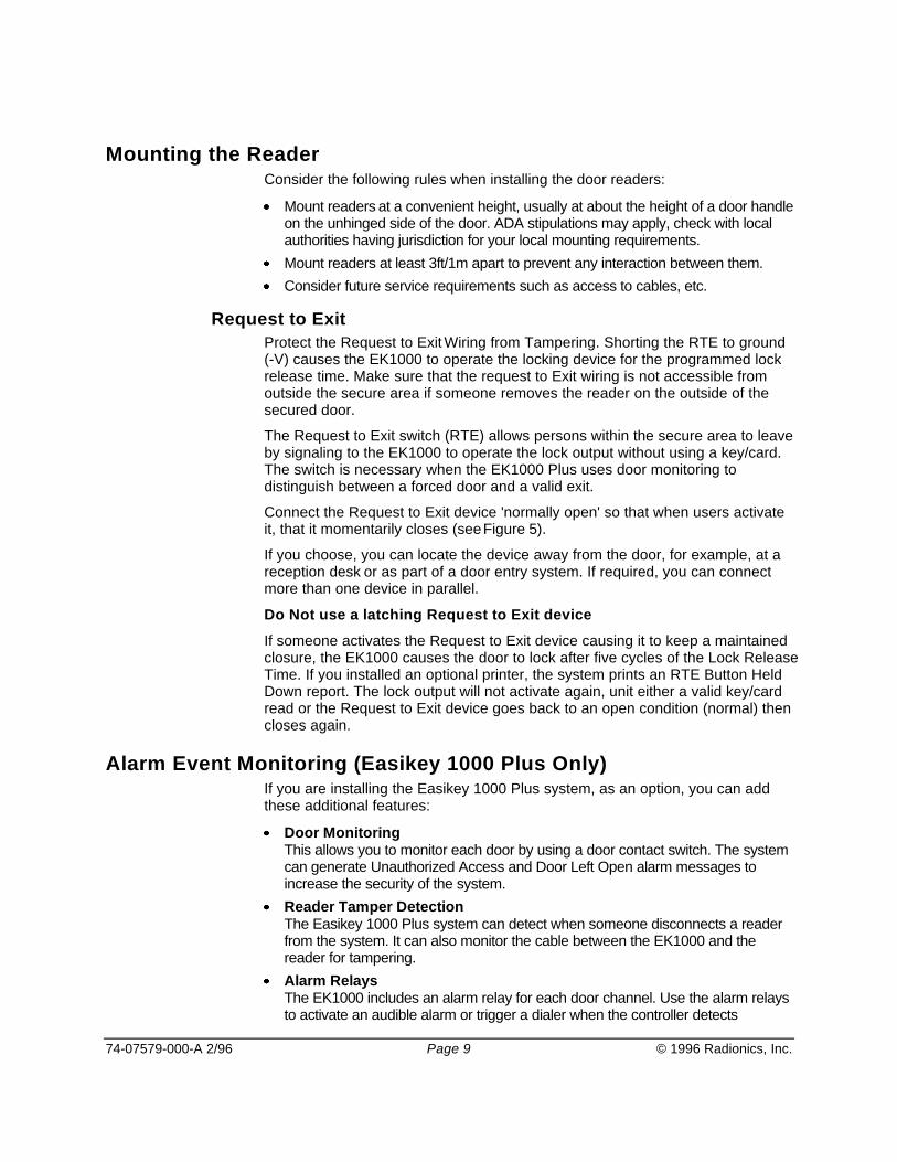
Free Exit and Emergency Override OptionWhen using the Emergency Override feature, the RTE signal is used to monitoran Emergency Override device, such as a fire pull switch or an input from a firecontrol panel. When using the Emergency Override feature, the EK1000 willactivate the lock output until the RTE input goes back to the normal (open)condition.
When this feature is used with an EK1000 Plus, a Free Exit report is generatedwhen the DC connection is opened.
Emergency Override affects Alarm Monitoring for the EK1000 Plus: Thisfeature disables reader tamper detection and door alarm monitoring for the doorthat you select for this feature. See Door Options on page 28 for furtherinformation about enabling this feature.
Figure 8: Connecting the Emergency Override Device
When connected as shown, operating the Emergency Override Device opens thedoor and causes the EK1000 to create an Emergency Override On report atthe printer. When the device is restored, the EK1000 creates an EmergencyOverride Off report and locks the door.
Think "Fire Safety": You should not use Emergency Override as the solemeans of escape. Even if this feature is being used it is still necessary to providea manual means of exit.

74-07579-000-A 2/96 Page 13 © 1996 Radionics, Inc.
Operating the System
Overview of System AdministrationThe System Administrator (Editor) is a person who supervises the Easikey 1000system. Usually the administrator adds and removes authorized users from thesystem, directs what times and days users can pass through doors, and printsreports that log daily access activity throughout the system.
Editor Key/Cards are standard Easikey electronic key/cards that have beenprogrammed into the system as a Sub Editor or Master Editor. This allows you touse normal key/cards that may grant access through the doors on the system forprogramming options.
The Easikey 1000 can have up to five System Administrators (Sub Editors) eachadministrator holding a special key/card that allows the administrator to performspecial functions with the access system.
The Easikey 1000 also has a System Supervisor who is called a Master EditorKey/Card. The Master Editor is the only editor that can Add or Delete the fiveSystem Administrators (Sub Editors) along with the ability to perform all otherprogramming options.
Using the Editor Key/CardsEditor key/cards allow the System Administrator to control the Easikey 1000.With an editor key/card, the administrator can control doors, add and removeauthorized users, print reports, and other special system functions.
There are two types of Editor key/cards. The difference between the two types isthat only the Master Editor can add or remove Sub Editors, otherwise both typeshave exactly the same function.
Master Editor Key/CardYou can only program one Master Editor key/card into the system. This specialkey/card enables or disables the other Editor Key/Cards and adds and deletesusers to the system. This key/card is typically stored in the Easikey 1000'senclosure, and used only to enable other Editor Key/Cards.
Your alarm company's installer created the Master Editor key/card when thesystem is first installed. You can change the Master Editor key/card at a laterdate if it is lost or stolen.
Sub Editor Key/CardsThe EK1000 requires you to present an Editor key/card to perform administrationtasks with the system. This allows the administrator access to editing functionsat the controller and also to accept alarms.
Editor Time-outIf after entering the Editor, no one presses any keys on the keypad or presents akey/card to the EK1000's internal reader for three minutes, the Editor will 'time-

74-07579-000-A 2/96 Page 14 © 1996 Radionics, Inc.
out'. This means it will exit the Editor Mode and return to the normal display. Toaccess the Editor mode again, you must present an Editor key/card to theinternal reader again.
How to Use the EK1000 Keypad and Editor ModeWhen you need to make changes tothe system, present one of the fiveEditor key/cards to the built-ininternal reader on the front of thedoor controller.
Use the External Reader to addalternate ID devices: If you areusing an external reader foralternate styles of ID device, use theexternal reader in place of thesystem's internal reader. If thekey/card is programmed as a validEditor, the screen displays "SEL?".
Using the KeypadAfter accessing the Editor mode by presenting one of the Editor key/cards to theinternal reader, the display will now show "SEL?". You may now press one of thefollowing keys on the keypad:
PIN/1 Displays the user key/card's PIN number when you present thekey/card
KEY/4 Allows you to add or edit system users
VOID/5 Allows you to remove users from the system
DOORS/6 Allows you to edit the door information and to control access doors
TIME/7 Allows you to create and edit Time Profiles and Time Periods forusers and doors
PRINT/8 Allows you to print system reports
INST/9 Access to clock setting, add/delete Editor keys, set door channelinterlock, set anti-pass back and upload/download
Arrow keys for moving around through records
SEL/SAVE Used when entering data or to confirm operations
ESC Leaves the editor
Entering DataYou will need to enter different types of information into the Editor. Here aresome important points to remember.
Whenever you add or change any data item you must press SEL/SAVE toconfirm and accept the changes.You can press ESC to leave the data unaltered.
Figure 9: The EK1000 display

74-07579-000-A 2/96 Page 15 © 1996 Radionics, Inc.
Different types of data entries use different methods:
Typing You must type numbers when entering a user number to the systemor to enter time in a Time Profile. When you press each number, thecursor position (a flashing underline) flashes at the current characterposition. You can use the arrow keys to move the cursorposition.
Toggling Pressing certain keys changes the state of the data entries. Forexample, when changing days of the week in Time Profiles,pressing 1 for Monday, 2 for Tuesday, etc., can turn days of theweek on or off. If the day is ON, pressing the key for that day willswitch it OFF.
System Displays and AlarmsThe EK1000 door controller will display various characters on its four-characterdisplay and produce a sound as a response to certain conditions. These aredescribed below.
Also included in this section are example printouts produced when a printer isattached to an Easikey 1000 when the various condition described takes place.
Power IndicatorsWhen the Editor is not being used (to add/delete users, etc.) the red and greenLEDs are used as power indicators. While in the Editor the power indicators willbe turned off. The power indicating LEDs operate normally as follows:
The red LED is constantly illuminated indicating that AC power is supplied to thesystem.The green LED is constantly illuminated when the battery (if any) is low (less than12 VDC).
Normal DisplaysWhen nothing is happening and the system is idle the display is blank, and no soundsare produced.
Whenever a door is opened normally or automatically, either with a key/card orby using a request-to-exit button, the display will look as shown here in Figure 10
Door 1 Open Door 2 Open Both Doors OpenFigure 10: Normal displays
74-07579-000-A 2/96 Page 16 © 1996 Radionics, Inc.
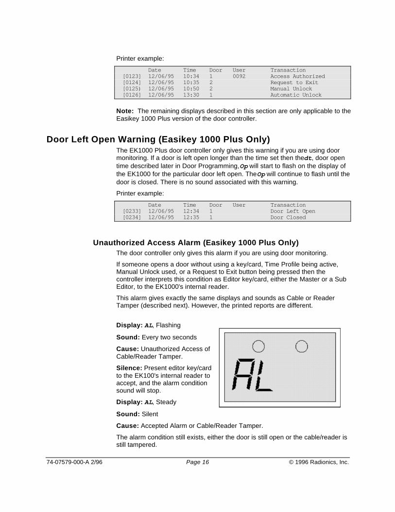
Printer example:
Date Time Door User Transaction[0123] 12/06/95 10:34 1 0092 Access Authorized[0124] 12/06/95 10:35 2 Request to Exit[0125) 12/06/95 10:50 2 Manual Unlock[0126] 12/06/95 13:30 1 Automatic Unlock
Note: The remaining displays described in this section are only applicable to theEasikey 1000 Plus version of the door controller.
Door Left Open Warning (Easikey 1000 Plus Only)The EK1000 Plus door controller only gives this warning if you are using doormonitoring. If a door is left open longer than the time set then the dt, door opentime described later in Door Programming, Op will start to flash on the display ofthe EK1000 for the particular door left open. The Op will continue to flash until thedoor is closed. There is no sound associated with this warning.
Printer example:
Date Time Door User Transaction[0233] 12/06/95 12:34 1 Door Left Open[0234] 12/06/95 12:35 1 Door Closed
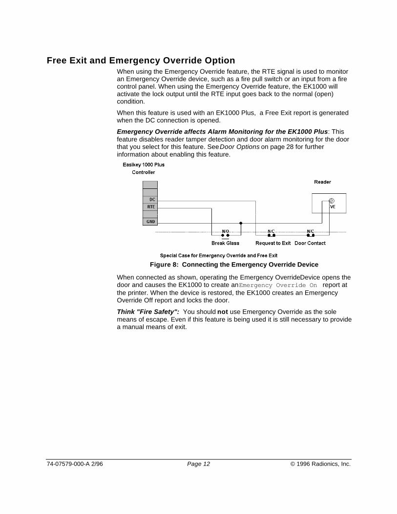
Unauthorized Access Alarm (Easikey 1000 Plus Only)The door controller only gives this alarm if you are using door monitoring.
If someone opens a door without using a key/card, Time Profile being active,Manual Unlock used, or a Request to Exit button being pressed then thecontroller interprets this condition as Editor key/card, either the Master or a SubEditor, to the EK1000's internal reader.
This alarm gives exactly the same displays and sounds as Cable or ReaderTamper (described next). However, the printed reports are different.
Display: AL, Flashing
Sound: Every two seconds
Cause: Unauthorized Access ofCable/Reader Tamper.
Silence: Present editor key/cardto the EK100's internal reader toaccept, and the alarm conditionsound will stop.
Display: AL, Steady
Sound: Silent
Cause: Accepted Alarm or Cable/Reader Tamper.
The alarm condition still exists, either the door is still open or the cable/reader isstill tampered.
74-07579-000-A 2/96 Page 17 © 1996 Radionics, Inc.
Printer example:
Date Time Door User Transaction[0278] 12/06/95 13:34 1 Unauthorized Access[0282] 12/06/95 13:35 1 MASTER Local Alarm Accepted[0285] 12/06/95 13:37 1 Alarm Cleared
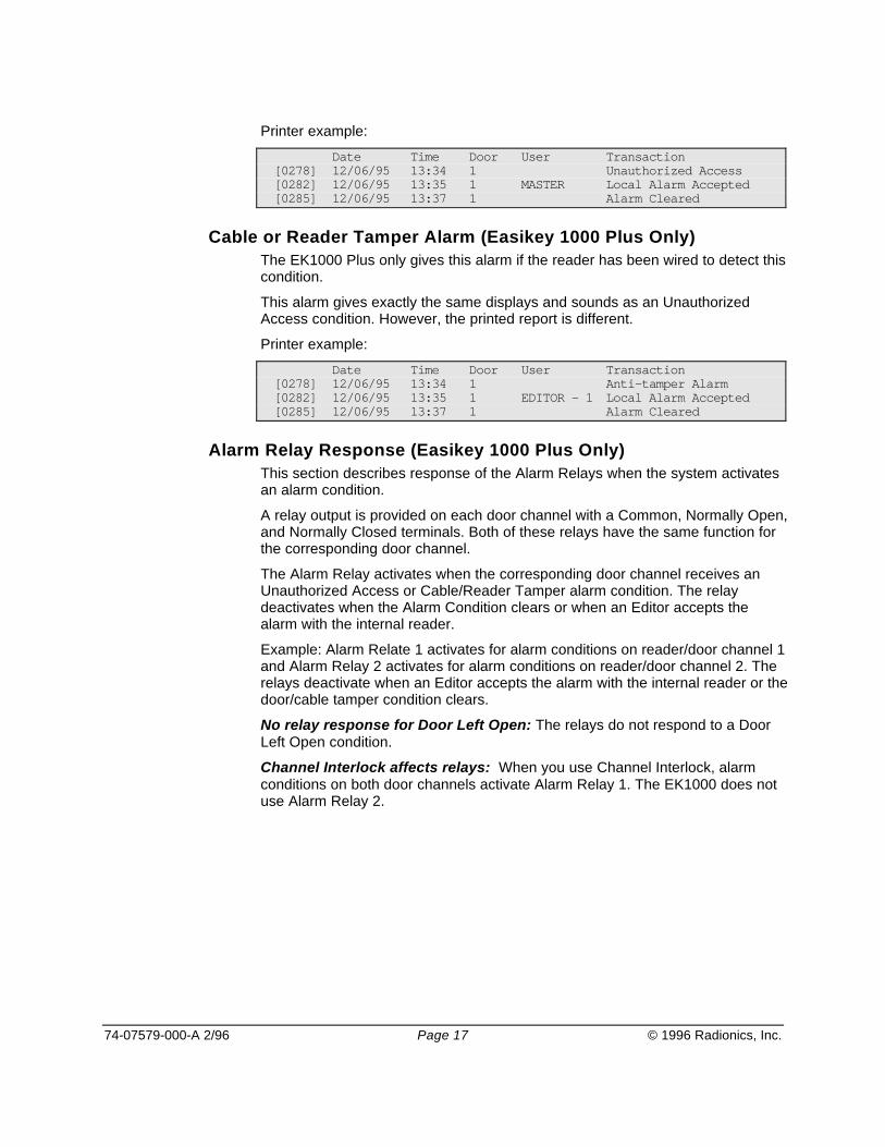
Cable or Reader Tamper Alarm (Easikey 1000 Plus Only)The EK1000 Plus only gives this alarm if the reader has been wired to detect thiscondition.
This alarm gives exactly the same displays and sounds as an UnauthorizedAccess condition. However, the printed report is different.
Printer example:
Date Time Door User Transaction[0278] 12/06/95 13:34 1 Anti-tamper Alarm[0282] 12/06/95 13:35 1 EDITOR - 1 Local Alarm Accepted[0285] 12/06/95 13:37 1 Alarm Cleared
Alarm Relay Response (Easikey 1000 Plus Only)This section describes response of the Alarm Relays when the system activatesan alarm condition.
A relay output is provided on each door channel with a Common, Normally Open,and Normally Closed terminals. Both of these relays have the same function forthe corresponding door channel.
The Alarm Relay activates when the corresponding door channel receives anUnauthorized Access or Cable/Reader Tamper alarm condition. The relaydeactivates when the Alarm Condition clears or when an Editor accepts thealarm with the internal reader.
Example: Alarm Relate 1 activates for alarm conditions on reader/door channel 1and Alarm Relay 2 activates for alarm conditions on reader/door channel 2. Therelays deactivate when an Editor accepts the alarm with the internal reader or thedoor/cable tamper condition clears.
No relay response for Door Left Open: The relays do not respond to a DoorLeft Open condition.
Channel Interlock affects relays: When you use Channel Interlock, alarmconditions on both door channels activate Alarm Relay 1. The EK1000 does notuse Alarm Relay 2.

74-07579-000-A 2/96 Page 18 © 1996 Radionics, Inc.
Programming the SystemThis section fully describes the logical programming sequence used for systemsetup and use. This includes programming the Master and Sub Editors into thesystem along with full database programming used for the system.
Applying PowerOnce you have installed the EK1000 door controller, readers and Request to Exitdevices, and have connected the wiring to the electric locking devices, you arenow ready to apply power to the EK1000. Follow this procedure for the initialstart-up of the system.
1. Disconnect all reader, lock, and printer terminal blocks from the EK1000.2. Connect the power supply to the corresponding terminals (AC or DC depending
on the power supply you install) to the EK1000. The screen may briefly display8888 and EK1000 will beep four times. The display will then clear and if youinstalled an AC power source, the Red power LED illuminates.
3. Connect the first reader.4. If installed, operate the RTE for the first reader. If you did not install an RTE
device, use a short piece of wire to short RTE to -V at the terminal block. Thedisplay should show Op and the green LED on the reader should illuminate.
5. Repeat for the second reader if used.6. Now proceed to install the Master Editor Key/card.
Installing the Master Editor Key/CardTo install the Master Editor Key/Card:
1. Press and release the small Reset button,SW1, located at the top left-hand corner ofthe circuit board. The EK1000 will beep fourtimes. While it is beeping, press and releasethe Reset button again. The display willflash horizontal bars.
2. Present a key/card to the EK1000's internalreader. This will become the Master EditorKey/Card.
3. The EK1000 will beep and the displayalternates between Clr and ALL?. Thismeans "Do you want to initialize and clear the whole database?" If this is anexisting installation, proceed to Item 4 now.
If this is a new door controller that no one has programmed, then the answershould be "Yes". Press VOID/5 followed by SEL/SAVE to initialize and clear thedatabase. The display clears and the EK1000 installs the Master EditorKey/Card.
4. If this is an existing installation and you do not want to erase the database, thenjust press ESC. Use this step if you are just replacing the Master EditorKey/Card. The display clears and the EK1000 replaces the Master EditorKey/Card.
Figure 11: Horizontal Barsin the Display

74-07579-000-A 2/96 Page 19 © 1996 Radionics, Inc.
Testing the Master Editor Key/Card and SystemPresent the new Master EditorKey/Card. The display shows SEL?indicating that you are in the Editormode and may select one of thefunctions .
When you install the Master EditorKey/Card after clearing thedatabase, the EK1000 sets thefollowing default parametersallowing you to immediately test thesystem:
The EK1000 also installs theMaster Editor Key/Card as Userkey/card 0001 with access through both doors and with no Time Profiles set (alltimes and days).Each door is given a Lock Release Time of five seconds.Each lock is set to fail-secure (power to unlock).
If this is a new installation, Radionics recommends that the readers andlocks should be tested now.
If you were replacing the Maser Editor Key/Card and have preserved the existingdatabase, the new Master Editor Key/Card is the only change. The EK1000 stillgives complete access to the Master Editor Key/Card. The Master EditorKey/Card normally loads into position 0001 replacing the old Master Editor IDunless someone has loaded another key/card into position 0001. If so, theEK1000 loads the Master Editor Key/Card into the next available position.
Figure 12: Entering the Editor

74-07579-000-A 2/96 Page 20 © 1996 Radionics, Inc.
Installing and Voiding Additional Sub Editor Key/CardsThis feature allows you to add or delete up to five additional Sub EditorKey/Cards (Administrators) in the system. System Administrators use Sub EditorKey/Cards to add and delete users from the system, and to assign users to TimeProfiles, etc. Only the Master Editor Key/Card can add or delete a Sub EditorKey/Card.
Adding a Sub Editor Key/Card
Step ExampleDisplay
Action
1 Present the Master Editor Key/Card to theEK1000's internal reader.
2 SEL? Press the INST/9 key.
3 SetC Press 3 times until "Edit" is displayed.
4 Edit Press SEL/SAVE.
5 E000 Present the new Sub Editor Key/Card to theEK1000's internal reader.
6 E002 At this time, if the red LED comes on and thenumber flashes then the Sub Editor Key/Cardalready exists in the database as an editor. If this isa new Sub Editor Key/Card then the green LED only will flash and the display will flash the SubEditor number. The example shows Sub EditorKey/Card 2 as the next available number.
7 E003 Present the Master Editor Key/Card to theEK1000's internal reader. The green LED will nowgo steady and the next available Sub Editor numberwill flash. You may add more Sub Editors now if youwish by repeating Steps 5-7. Press ESC if you arefinished programming Sub Editors.
8 SEL? Press ESC to leave Editor.

74-07579-000-A 2/96 Page 21 © 1996 Radionics, Inc.
Voiding an Sub Editor Key/CardYou cannot void the Master Editor Key/Card see Installing the Master EditorKey/Card on page 18 for instructions how to replace the Master Editor Key/Card.
Step ExampleDisplay
Action
1 Present the Master Editor Key/Card to theEK1000's internal reader.
2 SEL? Press the INST/9 key.
3 SetC Press 3 times until "Edit" is displayed.
4 Edit Press SEL/SAVE.
5 EOOO Either present the Sub Editor Key/Card that is to bevoided to the EK1000's internal reader
or: type the Sub Editor ID number and press SEL/SAVE
or: use to select the Sub Editor ID number and press SEL/SAVE.
Existing Sub Editor ID's or Key/Cards will flashalong with the red LED, key/cards that are not in theSub Editor database will flash with the green LED.
6 E003 Present the Master Editor Key/Card to delete theSub Editor Key/Card. There will be a short beepand the display will return to "SEL?".
7 SEL? Return to Step 2 above to delete more Sub EditorKey/Cards or press ESC to leave the Editor.

74-07579-000-A 2/96 Page 22 © 1996 Radionics, Inc.
Setting the ClockThis item sets the clock that the EK1000 uses for Time Profiles and the timestamp for printed reports.
Checking the clock and calendar regularly is important when using Time Profiles,or if you are using the printer to log events. Use the following procedure forsetting the clock:
If at any point you enter an invalid value, like 15 for the month, you will get a longbeep and the original value re-displayed.If the date is invalid, for example 02/31/95, then you will be returned to the yearvalue in Step 4 in the procedure below. Re-enter the correct month and date.
Step ExampleDisplay
Action
1 Present an Editor Key/Card to the EK100's internalreader.
2 SEL? Press INST/9
3 SetC Press SEL/SAVE
4 Yr95 Type the new year value (e.g. 95) and pressSEL/SAVE. Press to move to the next item.
5 Mt05 Type the new month value (e.g. 05) and pressSEL/SAVE. Press to move to the next item.
6 Dt06 Type the new date value (e.g. 06) and pressSEL/SAVE.
7 Dy2 Type the day of the week, Mon=1, Tue=2, Wed=3,Thu=4, Fri=5, Sat=6, Sun=7, (e.g. 2=Tuesday) andpress SEL/SAVE. Press to move to the nextitem.
8 Hr11 Type the hour and press SEL/SAVE. Press tomove to the next item. Note: Use military timeentries (e.g. 6:00 p.m. = 18:00 Hours).
9 Mn08 Type the minute (e.g. 08) and press SEL/SAVE.The clock is now set. Press ESC.
10 SEL? Press ESC to leave the Editor.
Change the time for Daylight Savings Time: The EK1000 follows a truecalendar year and recognizes leap year, but does not observe Daylight SavingsTime so you may need to make local time adjustments for Daylight SavingsTime.

74-07579-000-A 2/96 Page 23 © 1996 Radionics, Inc.
Time Profiles and Time Periods
Overview of Time ProfilesYou can restrict the use of a key/card to certain days and times. You can assignone of eight different Time Profiles to the key/card. If you assign a key/card aTime Profile of 0, the key/card has no time restrictions and its user can gainaccess through the system's doors 24 hours a day, 7 days a week.
Each Time Profile consists of up to three Time Periods, which contain the startand stop times along with the active days of the week.
Separate Doors and Users: Radionics recommends that you use differentTime Profiles for doors and users even if they are identical. This means that ifyou require a change to the automatic door opening times at a later date, thenthese can be achieved without affecting the users programmed into the systemkey/card access times.
When using Time Profiles it is important to check the time and date at regularintervals, say once a month, to ensure that the system operates accurately.
In addition to the three Time Periods, each Time Profile has a status setting,either ON or OFF. When a Time Profile is in use its Status will be ON, when it isOFF the effect depends on the application.
When applied to personnel, a Time Profile that is switched OFF will lock out allpersonnel with that profile until the Time Profile status is switched back ON.When applied to a door, a Time Profile that is switched OFF will stop the doorautomatically opening, it will also lock a door that is currently open according tothat Time Profile.
Time Profiles for DoorsWhen you assign Time Profiles to doors, they automatically open the door at thebegin time of each Time period and automatically close the door at the end timeof each Time Period contained within the Time Profile.
Time Profiles for User KeysTime profiles attached to a key/card allow access only when the time at whichthe key/card is presented falls within the Time Profile.
When Time Profiles Actually Begin and EndA Time Profile always starts at the beginning of the first minute of the timeperiod, for example, when the time changes from 8:59 a.m. to 9:00 a.m. A TimeProfile always finishes at the end of the final minute of the time period, forexample, if a time period is meant to expire exactly at 5:00 p.m. (17:00), thecorrect entry for the end time would be 4:59 p.m. (16:59).
Time periods Do Not Cross MidnightA time period cannot cross midnight. When it is necessary to cover such a timethen two Time Periods are required, one from the begin time up to midnight (use23:59), with another time period from midnight (use 00:00) to the end time.

74-07579-000-A 2/96 Page 24 © 1996 Radionics, Inc.
24-Hour OperationIf you give a door a Time Profile of zero it will require a key/card 24 hours a day,7 days a week. If you give a user's key/card a Time Profile of zero it will haveaccess 24 hours a day, 7 days a week. If you are never going to use timecontrols of any type then there is no need to set up any Time Profiles at all, justuse a Time Profile of zero for both doors and user key/cards.
Typical examples of Time Profiles are:
1. A public access door through which anyone can pass between 9:00 a.m. and5:00 p.m. (17:00), Monday to Friday, but outside these hours a key/card isrequired.
2. Selected staff members are only allowed access between 8:30 a.m. and 5:30p.m. (17:30), Monday to Friday; 8:30 a.m. to 12:00 p.m. Saturday.
3. Custodians are allowed access only between 7:00 a.m. and 9:00 a.m. Mondaythrough Saturday.
4. Night shift workers can gain access between 8:00 p.m. (20:00) and 6:00 a.m.Monday to Friday. Proper use would be two Time Periods the first being 20:00-23:59, and the second being 00:00-06:00 along with the corresponding days ofthe week.
Programming and Editing Time ProfilesSetting up a Time Profile is achieved by presenting an Editor Key/Card andpressing the TIME/7 key/card. The first display you will see is the status of TimeProfile 1 shown as t1St alternating with ON or OFF.
It is best to think of the Time Profile database as a grid, eight rows representingTime Profiles, ten columns being one for the Status and three for each TimePeriod. Use the keys to move a 'window' around the grid. If youattempt to move outside the window the EK1000 beeps.
Stat. begin End days begin End days begin End daysn tnSt tnAb tnAE tnAd tnbb tnbE tnbd tnCb tnCe tnCd1
on 0900 1700 0000 0000 0000 00002
on 0830 1730 0830 1200 0000 00003
on 0700 0900 0000 0000 0000 00004
on 2000 2359 0000 0800 0000 00005
oFF 0000 0000 0000 0000 0000 00006
oFF 0000 0000 0000 0000 0000 00007
oFF 0000 0000 0000 0000 0000 00008
oFF 0000 0000 0000 0000 0000 0000
Wherever you are in the grid you will see the item name alternating with the itemvalue. When you press a number keyed to make a change, the display will gosteady. Changes are made as follows:
Change the status by pressing the 1 key, for example, pressing 1 reverses thecurrent display. Press SEL/SAVE when the EK1000 displays the correct status.

74-07579-000-A 2/96 Page 25 © 1996 Radionics, Inc.
Change times by typing the four digits in 24-hour format, for example, for 1:00p.m. you would press 1,3,0, and 0 for a value of 13:00 followed by SEL/SAVE toconfirm your entry.The day periods are set by switching on or off seven vertical bars in the display.For instance, Monday to Friday is represented as seven vertical positioned acrossthe display, while Saturday only would be represented as a vertical bar in the sixthposition going from left to right. Changed each bar by pressing 1-7, where 1represents Monday, 2 Tuesday, through 7 for Sunday.

74-07579-000-A 2/96 Page 26 © 1996 Radionics, Inc.
To program Time Profile follow these steps:
Step ExampleDisplay
Action
1 Present an Editor key/card to theEK1000’s internal reader.
2 SEL? Press TIME/7
3 t1St / on The status of Time Profile 1 (may beeither on or oFF).To move to another Time Profile usethe keys to scroll through all eightTime Profiles.
4 t1St / oFF Press 1, the display will go to a steadyand show on. Notice if you press 1again the display will change back tooFF.Make sure on is displayed and pressSEL/SAVE to confirm the change.
5 t1St / on Press .
6 t1Ab / 0800 The display now shows the begin timeof period A. As an example type 0800for 8 a.m. followed by SEL/SAVE toconfirm the change. Notice how thedisplay goes steady as soon as youpress a key.
7 t1Ab / 0800 Press .
8 t1AE / 1700 The display now shows the end time ofperiod A. As an example type 1700(for 5:00 p.m.) followed by SEL/SAVEto confirm the change.
9 t1AE / 1700 Press .
10t1Ad /
The days of the week for this TimePeriod will be active for period A. Type1 for Monday, 2 for Tuesday, through7 for Sunday, for the displayed days ofthe week that this Time Period is to beactive. Press SEL/SAVE to confirmthe changes. You will notice that asyou press each number, thecorresponding bar doubles in size.Press the same number again and itgoes back to half size.
11t1Ad /
Press .
12 t1bb / 0800 The display now shows the begin timeof period B. As an example type 0800for 8am followed by SEL/SAVE toconfirm the change.
74-07579-000-A 2/96 Page 27 © 1996 Radionics, Inc.
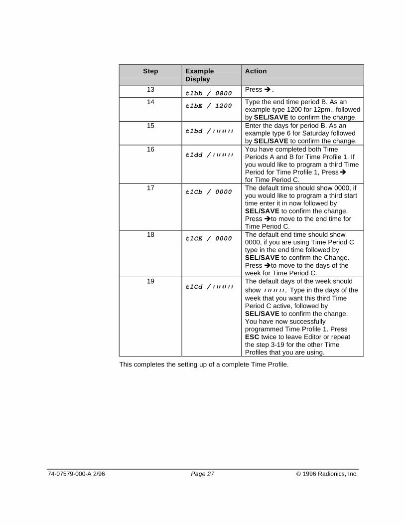
Step ExampleDisplay
Action
13 t1bb / 0800 Press .
14 t1bE / 1200 Type the end time period B. As anexample type 1200 for 12pm., followedby SEL/SAVE to confirm the change.
15t1bd /
Enter the days for period B. As anexample type 6 for Saturday followedby SEL/SAVE to confirm the change.
16t1dd /
You have completed both TimePeriods A and B for Time Profile 1. Ifyou would like to program a third TimePeriod for Time Profile 1, Press for Time Period C.
17 t1Cb / 0000 The default time should show 0000, ifyou would like to program a third starttime enter it in now followed bySEL/SAVE to confirm the change.Press to move to the end time forTime Period C.
18 t1CE / 0000 The default end time should show0000, if you are using Time Period Ctype in the end time followed bySEL/SAVE to confirm the Change.Press to move to the days of theweek for Time Period C.
19t1Cd /
The default days of the week shouldshow . Type in the days of theweek that you want this third TimePeriod C active, followed bySEL/SAVE to confirm the change.You have now successfullyprogrammed Time Profile 1. PressESC twice to leave Editor or repeatthe step 3-19 for the other TimeProfiles that you are using.
This completes the setting up of a complete Time Profile.

74-07579-000-A 2/96 Page 28 © 1996 Radionics, Inc.
Programming the Door DataWhen editing Door Data program entries, you will edit items for Lock ReleaseTime, Door Open Time, Door Time Profile, Door Options, Lock Mode, Free Exit,RTE Report, and the Set/Reset features. These program items are describedhere in detail.
Lock Release TimeThis is the amount of time that the EK1000 operates the lock output. Usually youwill want to enable the lock output a sufficient amount of time to allow people toopen the door. You may need to set a longer time for older or disabled people.When you using a EK1000 Plus with door monitoring, the EK1000 Plus doorcontroller clears any remaining lock release time as soon as the door contactcloses.
Door Open Time (Easikey 1000 Plus Systems Only)This is the amount of time that the EK1000 Plus allows at the end of the LockRelease Time before the controller activates a Door Left Open warning.Installation of a door contact is required.
You must enter a value here if you are using door monitoring and/or readertamper detection. A value of 0 disables door and reader tamper monitoring.
Door Time ProfileEnter in a Time Profile, 1-8 if the door requires automatic unlocking and lockingof secured doors. Enter in a 0 if the door is to remain secured at all times,requiring a valid key/card or request to exit to pass through the door.
Door OptionsThree are four options that you can program. The controller's display shows eachas a vertical bar, full height when set, half height when not set. Door Optionprogram items are listed here:
1 Lock ModeUNSET Lock operates as fail-secure, power applied to unlock door.
SET Lock operates as fail-safe, continuous power to keep door secure,removed power to unlock.

74-07579-000-A 2/96 Page 29 © 1996 Radionics, Inc.
2 Free Exit/Emergency OverrideThis option modifies the way that the DC (door contact) and RTE (request toexit) are monitored.
UNSET The EK1000 Plus monitors door contact and reader/cable tamper.(RTE Programmed for Request to Exit)
SET The EK1000 Plus will give Free Exit report without an alarm whenthe door is opened without a valid key/card or request to exit. On allversions of the EK1000 the RTE gives Emergency Override Onreport and unlocks the door when triggered (closed), EmergencyOverride Off report and locks the door when the RTE goes back tothe normal condition (opened).
3 RTE ReportThis option controls the type of report that the controller prints when RTE isoperated.
UNSET Request to Exit
SET Request for Entry
4 Not Used - Leave UNSETThis option will be reserved for future use, and must remain unset for proper
operation.
UNSET Normal default setting.
SET Reserved for future use.
5 Set/ResetThis option programs the door to open normally, following the programmed LockRelease Time, or to operate as a Set/Reset (toggle the output state) engagingthe lock output and remaining engaged until a user presents a valid key/cardagain.
UNSET Presenting a key/card to the reader releases the lock for the timespecified by the Lock Release Time.
SET Presenting a key/card to the reader releases (engages) the lockoutput. It stays in this state until a user presents a key/card again tothe reader, then the lock output will disengages.

74-07579-000-A 2/96 Page 30 © 1996 Radionics, Inc.
Using the Doors FunctionPress at any tine to move between Door 1 and Door 2.
Press at any time to move between parameters. The parameters arepresented in the order described earlier in Door Options.
Press ESC at any time to return to SEL?
Step Example Display Action
1 Present an Editor key/card to the EK1000’sinternal reader.
2 SEL? Press DOORS/6.
3 d1Lt / 005 Lock Release Time for door 1.Either: Type a new time, 0-255, followed bySEL/SAVE to confirm the change, then press to go to door 2,or Press to go to next parameter.
4 d1dt / 000 Door Open Time for door 1 used for the EK1000Plus only.Either:Type a new time, 0-255, followed by SEL/SAVEto confirm the change, then Press to go todoor 2or Press to go to next parameter.
5 d1tP / 0 Time Profile for door 1. Enter in the Time Profilenumber 1-8, if used, for automatically unlock andlocking the door. Set as 0, for no auto unlock/lockfeature.Either: Type a new Time Profile 0-8 followed bySEL/SAVE to confirm the change, then Press to go to door 2,or Press to go to nextparameter.
6 d1oP /IIIII Door Options for door 1. See Door Options onpage 28 for full descriptions of each option.Either: Press 1,2,3, or 5 to set or unset followedby SEL/SAVE to confirm the change, then Press
to go to door 2,or Press to go to nextparameter.
7 d1UL / LoC Manual Lock/Unlock for door 1. Used formanually Locking and Unlocking doors 1 or 2.
See Manual Lock/Unlock for Controlling theDoors on page 32 section for full details of use.
Press ESC twice to leave Editor or repeat thestep 3-7 for entering the door parameters fordoor 2.

74-07579-000-A 2/96 Page 31 © 1996 Radionics, Inc.
Channel InterlockThis feature allows the use of both door 1 and 2 readers as an entry and exit,interlocking the lock output to a single output for both readers.
When you use a reader on both sides of a door to monitor both entry and exitthen it is only necessary to interlock to one lock output. The EK1000 operatesthe same lock output, Lock 1 for Reader 1 and Reader 2. The EK1000 does notuse Lock 2. If you use Door Monitoring and RTE, the EK1000 assigns them tochannel 1 also.
Programming Channel InterlockStep Example
DisplayAction
1 Present an Editor key/card to the EK1000’sinternal reader.
2 SEL? Press INST/9
3 SetC Press 4 times until the display shows P00.
4 P00or POO. Ifchannelinterlock is set.
Press to toggle Channel Interlock ON/OFF,followed by SEL/SAVE to confirm the change.
5 SEL? Press ESC to leave Editor.
Anti-PassbackIf Channel Interlock has been used, this additional feature causes the EK1000 tomonitor both the entry and exit through the secured area. When you enable Anti-Passback, the user may enter and exit only by using their key/card each way. Ifthe EK1000 logs two entries attempts through a door by the same key/cardwithout an exit between, it will not allow access to be granted for the secondpresentation of the key/card.
When you use two readers to control both entry into an area and exit out of thearea then you may set anti-passback. If a user attempts to use the key/card toenter the area again, the EK1000 causes a No Access; Pass Back report onthe printer. As with Channel Interlock, Channel 1 is considered the entry readerand Channel 2 the exit reader.
You can cause Passback to be active until the user presents a key/card to leavethe area, or you can assign a time limit, after which the user can present thekey/card to enter the area again. The time limit is useful if people are likely toleave the area without using their keys or cards, without the time limit they wouldbe unable to get back in the area. This feature is often referred to a “ForgivenessTime.”

74-07579-000-A 2/96 Page 32 © 1996 Radionics, Inc.
Programming Anit-Passback
Step ExampleDisplay
Action
1 Present an Editor key/card to the EK1000’sinternal reader.
2 SEL? Press INST/9
3 SetC Press 4 times until P00 is displayed.
4 P00 or
P00. if ChannelInterlock is set.
Type a value, 0-60 (0 to unset), followed bySEL/SAVE to confirm the change.
0 No pass back
1 Pass back with no forgiveness time limit.
2-60 Number of minutes after which a key/cardwill work again if it is not used to leave thearea.
5 P15 (with an anti-passback timeset to 15 mins)
As an example, a value of 15 sets Anti-Passbackwith a forgiveness time of 15 minutes.
6 SEL? Press ESC to leave Editor.
Manual Lock/Unlock for Controlling the DoorsIt is possible to manually lock and unlock a door from the EK1000. It may benecessary to do this, for instance, when a door needs to be kept unlocked whilecontractors are working in an area, or equipment is being moved around. Also adoor that is normally open or a Time Profile may need to be locked while areceptionist or guard is not available.
Doors controlled by a Time ProfileManual lock will lock the door. The EK1000 requires users to present theirkeys/cards to gain access when doors are locked. If you do not manually unlockthe door, the door will unlock again at its next automatic opening time accordingto the Time Profile assigned.
If you manually unlock a door, and then do not manually lock the door, the doorwill lock again at its next automatic closing time according to the Time Profileassigned.
Doors not controlled by a Time ProfileManual unlock will unlock the door and it will stay unlocked until manually lockedagain.
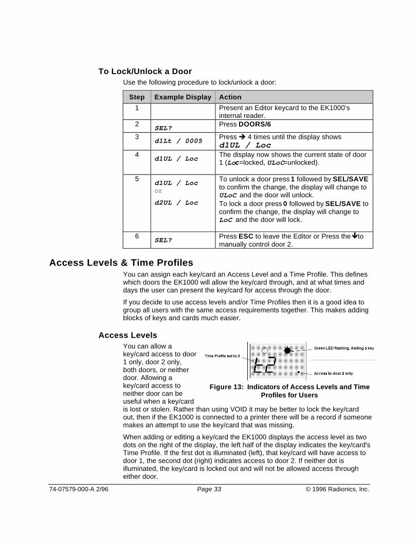
74-07579-000-A 2/96 Page 33 © 1996 Radionics, Inc.
To Lock/Unlock a DoorUse the following procedure to lock/unlock a door:
Step Example Display Action1 Present an Editor keycard to the EK1000’s
internal reader.2 SEL? Press DOORS/6
3 d1Lt / 0005 Press 4 times until the display showsd1UL / Loc.
4 d1UL / Loc The display now shows the current state of door1 (Loc=locked, ULoC=unlocked).
5 d1UL / Locor
d2UL / Loc
To unlock a door press 1 followed by SEL/SAVEto confirm the change, the display will change toULoC and the door will unlock.To lock a door press 0 followed by SEL/SAVE toconfirm the change, the display will change toLoC and the door will lock.
6 SEL? Press ESC to leave the Editor or Press the tomanually control door 2.
Access Levels & Time ProfilesYou can assign each key/card an Access Level and a Time Profile. This defineswhich doors the EK1000 will allow the key/card through, and at what times anddays the user can present the key/card for access through the door.
If you decide to use access levels and/or Time Profiles then it is a good idea togroup all users with the same access requirements together. This makes addingblocks of keys and cards much easier.
Access LevelsYou can allow akey/card access to door1 only, door 2 only,both doors, or neitherdoor. Allowing akey/card access toneither door can beuseful when a key/cardis lost or stolen. Rather than using VOID it may be better to lock the key/cardout, then if the EK1000 is connected to a printer there will be a record if someonemakes an attempt to use the key/card that was missing.
When adding or editing a key/card the EK1000 displays the access level as twodots on the right of the display, the left half of the display indicates the key/card'sTime Profile. If the first dot is illuminated (left), that key/card will have access todoor 1, the second dot (right) indicates access to door 2. If neither dot isilluminated, the key/card is locked out and will not be allowed access througheither door.
Figure 13: Indicators of Access Levels and TimeProfiles for Users

74-07579-000-A 2/96 Page 34 © 1996 Radionics, Inc.
User (Key/Card) NumbersWhen you add a new key/card to the EK1000, the EK1000 door controllerassigns the key/card a number between 0001 and 1000. Normally when you adda key/card the controller assigns it the first available number in the list. Forexample if a system contained keys 0001, 0002, 0003, 0004 and 0006, theEK1000 would assign the next key/card added to number 0005. The EK1000would assign next following key/cards to numbers 0007, 0008 and so on. It ispossible to override the automatic numbering and give a key/card a specificnumber, provided the number is not currently being used by another key/card.
It is important to keep a record of key/card numbers you issue and who theybelong to on the Easikey 1000/1000 Plus Programming Record Sheet (74-07580-000). It may be necessary to void a lost key/card at a later date, in whichcase, you must know the number given to the lost key/card if you do not have itin your possession.
Adding or Editing UsersFollow this procedure for adding a new key/card to the EK1000. If you are addingmore than one new key/card, see Adding Several Keys on page 36.
Step Example Display Action1 Present an Editor key/card to the EK1000’s
internal reader.2 SEL? Press the KEY/4 key.
3 0000 Present a new key/card to the EK1000’s internalreader.
4
0019 / t0..
At this point if both the green and red LEDs comeon then the key already exists in the database andmay be edited (see Editing a Key). If this is a newkey/card then the green LED only will flash andthe display will alternate between the nextavailable key/card number and the Time Profileand Access Level. This example shows key/card0019 as the next available number.At this point you may wish to select your ownnumber rather than the number given by theEK1000. If not then go to step 6 below.To select an alternative number pressSEL/SAVE, the display will change to 0000.
5 0000 Now either type in the number you require andpress SEL/SAVE to confirm the change, or usethe and keys to go up and down the list ofnumbers. Numbers already assigned will flashwith the red and green LEDs steady, free numberswill alternate with their Time Profile and AccessLevel and the green LED flashing. PressSEL/SAVE to confirm the number that has beenchosen.

74-07579-000-A 2/96 Page 35 © 1996 Radionics, Inc.
Step Example Display Action6 0019 / t0.. Now changes can be made to the Access Level
and Time Profile. If no changes are to be made goto step 8.
7
0019 / t1 .
To change the Time Profile press 0-8 for theTime Profile you wish to apply. (As soon as youpress a key the display will stop alternating). ATime Profile of 0, allows for 24 hour access, 7days a week. Press SEL/SAVE to confirm thechange. The display will start flashing again.To change Access Levels press to toggleon/off the dot for door 1, and to toggle on/offthe dot for door 2. Press SEL/SAVE to confirmthe change.The example shows key 0019 with Time Profile 1and access through door 2 only.
8
0020 / t1 .
Present the Editor key/card (it must be the sameone as used in step 1 above) to the EK1000’sinternal reader. The green LED will now go steadyand the next available number will flash.If you wish to add more keys see Adding SeveralKey/Cards next otherwise press ESC.
9 SEL? Press ESC to leave Editor.
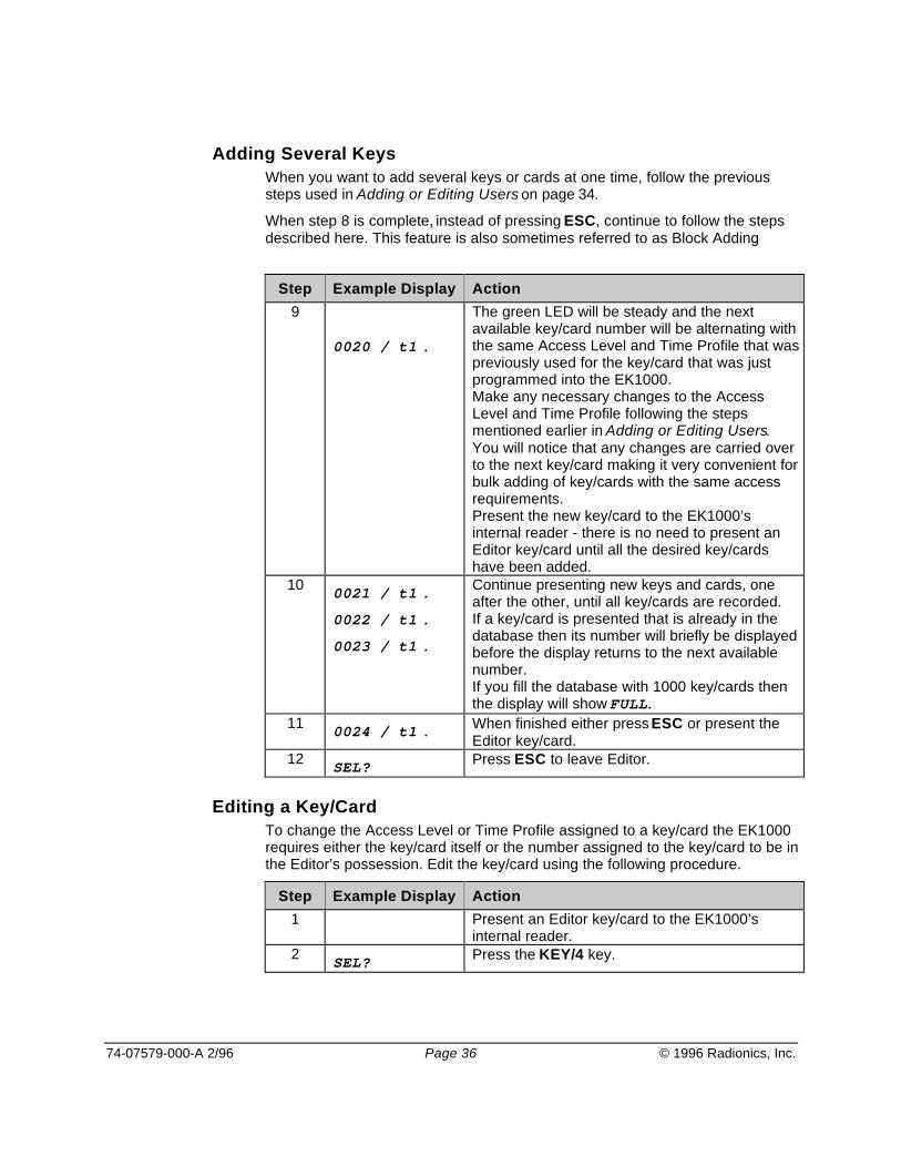
74-07579-000-A 2/96 Page 36 © 1996 Radionics, Inc.
Adding Several KeysWhen you want to add several keys or cards at one time, follow the previoussteps used in Adding or Editing Users on page 34.
When step 8 is complete, instead of pressing ESC, continue to follow the stepsdescribed here. This feature is also sometimes referred to as Block Adding.
Step Example Display Action9
0020 / t1 .
The green LED will be steady and the nextavailable key/card number will be alternating withthe same Access Level and Time Profile that waspreviously used for the key/card that was justprogrammed into the EK1000.Make any necessary changes to the AccessLevel and Time Profile following the stepsmentioned earlier in Adding or Editing Users.You will notice that any changes are carried overto the next key/card making it very convenient forbulk adding of key/cards with the same accessrequirements.Present the new key/card to the EK1000’sinternal reader - there is no need to present anEditor key/card until all the desired key/cardshave been added.
10 0021 / t1 .
0022 / t1 .
0023 / t1 .
Continue presenting new keys and cards, oneafter the other, until all key/cards are recorded.If a key/card is presented that is already in thedatabase then its number will briefly be displayedbefore the display returns to the next availablenumber.If you fill the database with 1000 key/cards thenthe display will show FULL.
11 0024 / t1 . When finished either press ESC or present theEditor key/card.
12 SEL? Press ESC to leave Editor.
Editing a Key/CardTo change the Access Level or Time Profile assigned to a key/card the EK1000requires either the key/card itself or the number assigned to the key/card to be inthe Editor’s possession. Edit the key/card using the following procedure.
Step Example Display Action1 Present an Editor key/card to the EK1000’s
internal reader.2 SEL? Press the KEY/4 key.

74-07579-000-A 2/96 Page 37 © 1996 Radionics, Inc.
Step Example Display Action3 0000 Either: present the key/card that you wish to edit
to the EK1000’s internal reader,or: type the key/card number and press
SEL/SAVE to confirm the numberentered,
or: use to select the key/card numberand press SEL/SAVE to confirm thenumber.
If the green LED is flashing then the key/cardpresented is not in the system or the numberselected is unused.
4 0019 / t1.. If the key/card presented or the number selectedis in the database then both red and green LEDswill be on, and the display will be alternatingbetween the key/card number and the AccessLevel and Time Profile assignment. In theexample key/card 0019 has been selected, andhas Time Profile 1 assigned and is allowedthrough both doors.Make any changes as described in Step 7 ofAdding or Editing Users on page 34.
5 t2 . The display will go steady, press SEL/SAVE toconfirm the change.
6 0019 / t2 . You will be returned to the alternating display.Return to step 3 if you want to change otherkey/cards or Press SEL/SAVE if you want totype another number.Otherwise press ESC.
7 SEL? Press ESC to leave the Editor.
Displaying a Key/Card PIN NumberIf you are using Readykey PIN readers with the system, it is necessary to knowthe PIN Number before you issue the key/card to the user. The user mustpresent the key/card to the reader, then the user must enter the PIN Number toopen the door. To find the PIN associated with a key/card follow these stepsdescribed here.
Step Example Display Action
1 Present an Editor key/card to the EK1000’sinternal reader.
2 SEL? Press PIN/1 key.
3 Show/Id Present the key/card desired to the EK1000’sinternal reader to acquire the PIN Number.
4 1234 The PIN Number displayed.
The EK1000 does not assign the PIN Number: You cannot change the PIN. It iscontained within the key/card and not programmable.
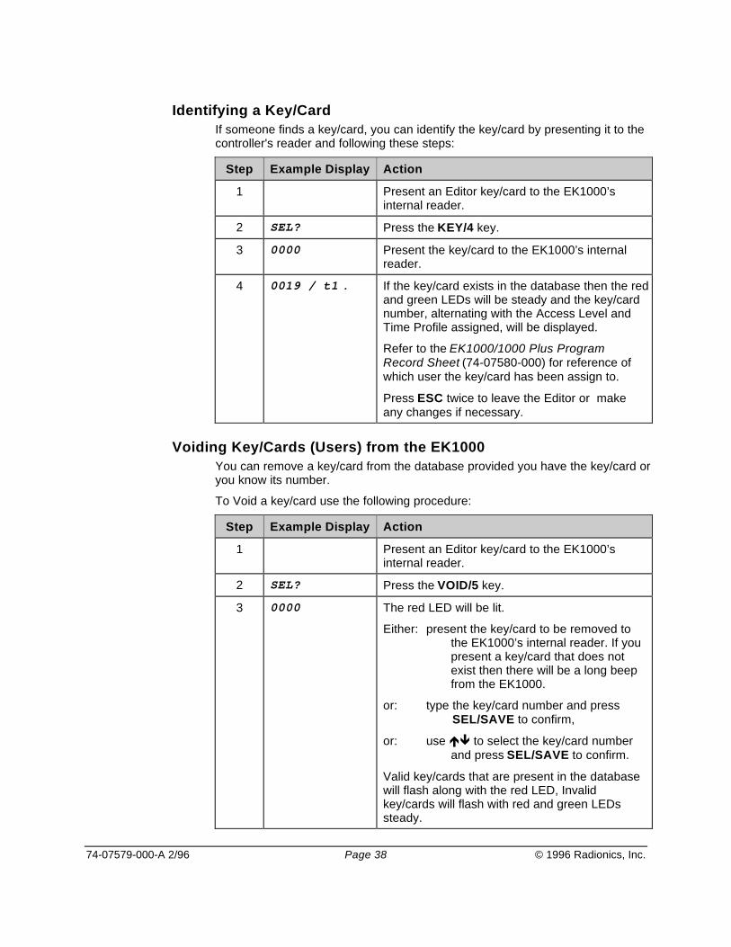
74-07579-000-A 2/96 Page 38 © 1996 Radionics, Inc.
Identifying a Key/CardIf someone finds a key/card, you can identify the key/card by presenting it to thecontroller's reader and following these steps:
Step Example Display Action
1 Present an Editor key/card to the EK1000’sinternal reader.
2 SEL? Press the KEY/4 key.
3 0000 Present the key/card to the EK1000’s internalreader.
4 0019 / t1 . If the key/card exists in the database then the redand green LEDs will be steady and the key/cardnumber, alternating with the Access Level andTime Profile assigned, will be displayed.
Refer to the EK1000/1000 Plus ProgramRecord Sheet (74-07580-000) for reference ofwhich user the key/card has been assign to.
Press ESC twice to leave the Editor or makeany changes if necessary.
Voiding Key/Cards (Users) from the EK1000You can remove a key/card from the database provided you have the key/card oryou know its number.
To Void a key/card use the following procedure:
Step Example Display Action
1 Present an Editor key/card to the EK1000’sinternal reader.
2 SEL? Press the VOID/5 key.
3 0000 The red LED will be lit.
Either: present the key/card to be removed tothe EK1000’s internal reader. If youpresent a key/card that does notexist then there will be a long beepfrom the EK1000.
or: type the key/card number and pressSEL/SAVE to confirm,
or: use to select the key/card numberand press SEL/SAVE to confirm.
Valid key/cards that are present in the databasewill flash along with the red LED, Invalidkey/cards will flash with red and green LEDssteady.

74-07579-000-A 2/96 Page 39 © 1996 Radionics, Inc.
Step Example Display Action
4 0019 Present the Editor key/card to delete thekey/card desired.
There will be a confirming beep and the displaywill return to SEL?.
5 SEL? Return to step 2 above to delete more key/cardsfrom the database or press ESC to leave theEditor.
Voiding Editor keys: If you need to void and Editor key/card, see Installingand Voiding Additional Sub Editor Key/Cards for more information.
Additional System Options
Software Version DisplayThis feature allows for recording the EK1000's current software version. You mayneed this information for Technical Support personnel to explain what featureoptions are available for your current EK1000.
Step Example Display Action
1 Present an Editor key/card to the EK1000’sinternal reader.
2 SEL? Press INST/9
3 SetC Press 5 times until v??? is displayed. The“?”s represent the version software number.
4 v100 In this case the display shows version 1.00,.This is the software revision for this EK1000.Press ESC.
5 SEL? Press ESC to leave Editor.

74-07579-000-A 2/96 Page 40 © 1996 Radionics, Inc.
Upload/Download OptionThis feature enables communication between two EK1000s for a databasetransfer from one EK1000 to another.
It is possible to use the printer ports on two Easikey 1000 controllers to copy thedatabase from one to the other. To do this a cable will need to be made up asfollows:
Use 22 gauge, four-wire, unshielded cable, maximum length 30ft/15m.
Easikey 1000Printer Port
Easikey 1000Printer Port
GND (27) ----------- GND (27)
DTR (28) ----------- CTS (30)
RX (29) ----------- TX (31))
CTS (30) ----------- DTR (28)
TX (31) ----------- RX (29
After you connect the two controllers, use the following procedure to transfer thedatabase records between the two EK1000s:
Press ESC to cancel the transfer at any time.
Step Sending Unit Receiving Unit Action1 Present an Editor key/card to
each EK1000’s internal reader.2 SEL? SEL? Press INST/9 at each controller.
3 SetC SetC Press at each EK1000.
4 in in Press again at sendingEK1000 only.
5 oUt in To start the transfer:Press SEL/SAVE twice on thereceiving EK1000 then:Press SEL/SAVE on thesending EK1000.
6 oUt / nnn in / in The sending controller willdisplay oUt alternating with thepercentage complete.The receiving controller will flashin.When complete, both displayswill return to SEL?
7 SEL? SEL? Press ESC to leave Editor.
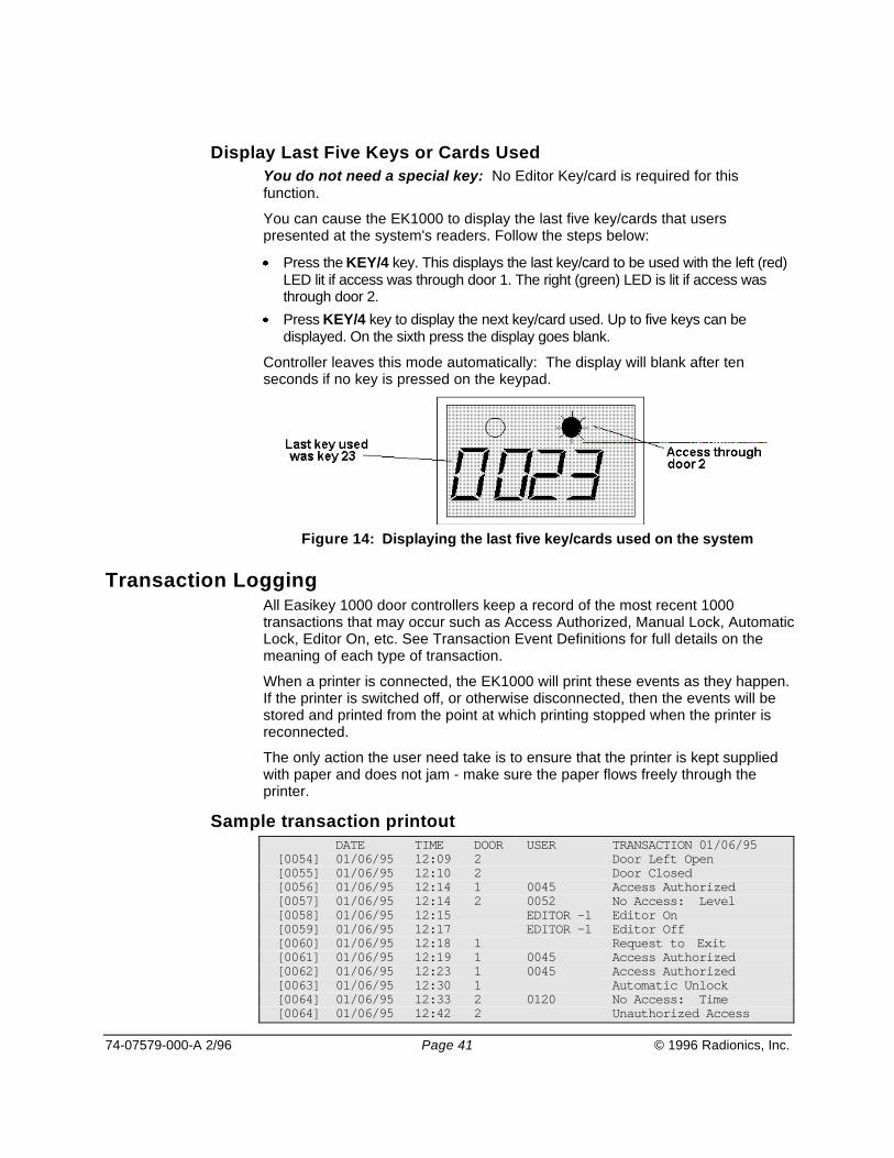
74-07579-000-A 2/96 Page 41 © 1996 Radionics, Inc.
Display Last Five Keys or Cards UsedYou do not need a special key: No Editor Key/card is required for thisfunction.
You can cause the EK1000 to display the last five key/cards that userspresented at the system's readers. Follow the steps below:
Press the KEY/4 key. This displays the last key/card to be used with the left (red)LED lit if access was through door 1. The right (green) LED is lit if access wasthrough door 2.Press KEY/4 key to display the next key/card used. Up to five keys can bedisplayed. On the sixth press the display goes blank.
Controller leaves this mode automatically: The display will blank after tenseconds if no key is pressed on the keypad.
Figure 14: Displaying the last five key/cards used on the system
Transaction LoggingAll Easikey 1000 door controllers keep a record of the most recent 1000transactions that may occur such as Access Authorized, Manual Lock, AutomaticLock, Editor On, etc. See Transaction Event Definitions for full details on themeaning of each type of transaction.
When a printer is connected, the EK1000 will print these events as they happen.If the printer is switched off, or otherwise disconnected, then the events will bestored and printed from the point at which printing stopped when the printer isreconnected.
The only action the user need take is to ensure that the printer is kept suppliedwith paper and does not jam - make sure the paper flows freely through theprinter.
Sample transaction printoutDATE TIME DOOR USER TRANSACTION 01/06/95
[0054] 01/06/95 12:09 2 Door Left Open[0055] 01/06/95 12:10 2 Door Closed[0056] 01/06/95 12:14 1 0045 Access Authorized[0057] 01/06/95 12:14 2 0052 No Access: Level[0058] 01/06/95 12:15 EDITOR -1 Editor On[0059] 01/06/95 12:17 EDITOR -1 Editor Off[0060] 01/06/95 12:18 1 Request to Exit[0061] 01/06/95 12:19 1 0045 Access Authorized[0062] 01/06/95 12:23 1 0045 Access Authorized[0063] 01/06/95 12:30 1 Automatic Unlock[0064] 01/06/95 12:33 2 0120 No Access: Time[0064] 01/06/95 12:42 2 Unauthorized Access
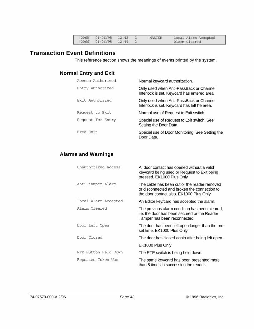
74-07579-000-A 2/96 Page 42 © 1996 Radionics, Inc.
[0065] 01/06/95 12:43 2 MASTER Local Alarm Accepted[0066] 01/06/95 12:44 2 Alarm Cleared
Transaction Event DefinitionsThis reference section shows the meanings of events printed by the system.
Normal Entry and ExitAccess Authorized Normal key/card authorization.
Entry Authorized Only used when Anti-PassBack or ChannelInterlock is set. Key/card has entered area.
Exit Authorized Only used when Anti-PassBack or ChannelInterlock is set. Key/card has left he area.
Request to Exit Normal use of Request to Exit switch.
Request for Entry Special use of Request to Exit switch. SeeSetting the Door Data.
Free Exit Special use of Door Monitoring. See Setting theDoor Data.
Alarms and Warnings
Unauthorized Access A door contact has opened without a validkey/card being used or Request to Exit beingpressed. EK1000 Plus Only
Anti-tamper Alarm The cable has been cut or the reader removedor disconnected and broken the connection tothe door contact also. EK1000 Plus Only
Local Alarm Accepted An Editor key/card has accepted the alarm.
Alarm Cleared The previous alarm condition has been cleared,i.e. the door has been secured or the ReaderTamper has been reconnected.
Door Left Open The door has been left open longer than the pre-set time. EK1000 Plus Only
Door Closed The door has closed again after being left open.
EK1000 Plus Only
RTE Button Held Down The RTE switch is being held down.
Repeated Token Use The same key/card has been presented morethan 5 times in succession the reader.

74-07579-000-A 2/96 Page 43 © 1996 Radionics, Inc.
No AccessNo Access: Unknown ID A key/card has been presented that is not
currently enrolled into the EK1000’s database.
No Access: Locked Out A key/card with no access allowed at either doorhas been presented.
No Access: Level A key/card with no access allowed at the doorhas been presented. The key/card is allowedonly through the other door.
No Access: Time A key/card currently excluded from this door witha Time Profile.
No Access: Pass Back A key/card has been excluded because it hasattempted to be used twice on the same readerin succession.
Door EventsAutomatic Lock The door has locked automatically via a Time
Profile.
Automatic Unlock The door has unlocked automatically via a TimeProfile.
Manual Lock An Editor has Manually Locked the door.
Manual Unlock An Editor has Manually Unlocked the door.
Other EventsEditor on An Editor key/card has entered the Editor.
Editor Off An Editor key/card has left the Editor or theEditor has timed-out.
Emergency Override On Special use of Request to Exit. The switch ismonitoring an emergency switch (e.g. a breakglass).
Emergency Override Off Special use of Request to Exit. The switch ismonitoring an emergency switch (e.g. a breakglass).
Unit Closed Down Power removed from the EK1000.
Unit Started Up The EK1000 has been switched on.

74-07579-000-A 2/96 Page 44 © 1996 Radionics, Inc.
Printing Reports
User Selected ReportsThere are three features accessible to the user from the PRINt/8 key.
Printout of the database including Personnel, Time Profiles and Door Data.Printout of transactions applying to an individual key/card.Clearing all transactions in the controller.
To Print the DatabaseThis function prints personnel, Time Profile, and Door Data. The printer willautomatically go to the top of a new page, the display will show the progress ofthe report.
Press ESC to interrupt the printout at any time.
1 Present an Editor key/card to the EK1000’sinternal reader.
2 SEL? Press the PRINT/8 key
3 PrdA Press SEL/SAVE to start database printout.
4 db / Prnt
tP / Prnt
dr / Prnt
..printing personnel database
..printing Time Profiles
..printing door data
5 SEL? Press ESC to leave Editor.
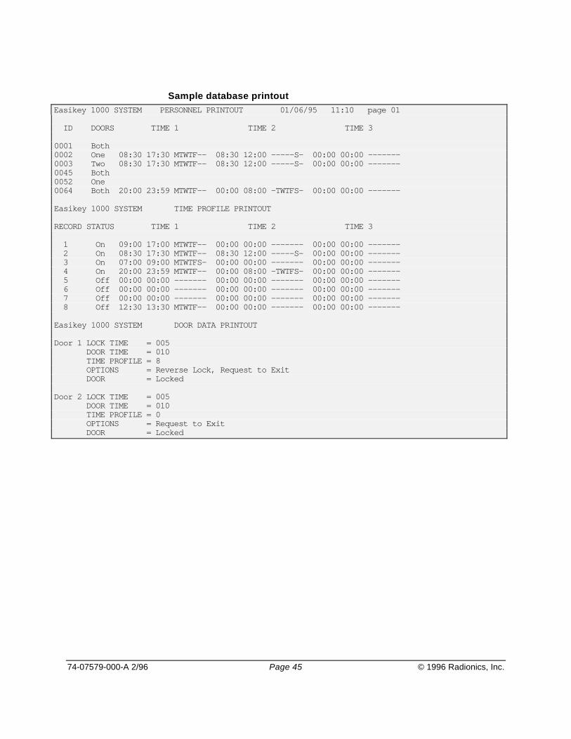
74-07579-000-A 2/96 Page 45 © 1996 Radionics, Inc.
Sample database printoutEasikey 1000 SYSTEM PERSONNEL PRINTOUT 01/06/95 11:10 page 01
ID DOORS TIME 1 TIME 2 TIME 3
0001 Both 0002 One 08:30 17:30 MTWTF-- 08:30 12:00 -----S- 00:00 00:00 -------0003 Two 08:30 17:30 MTWTF-- 08:30 12:00 -----S- 00:00 00:00 -------0045 Both0052 One0064 Both 20:00 23:59 MTWTF-- 00:00 08:00 -TWTFS- 00:00 00:00 -------
Easikey 1000 SYSTEM TIME PROFILE PRINTOUT
RECORD STATUS TIME 1 TIME 2 TIME 3
1 On 09:00 17:00 MTWTF-- 00:00 00:00 ------- 00:00 00:00 ------- 2 On 08:30 17:30 MTWTF-- 08:30 12:00 -----S- 00:00 00:00 ------- 3 On 07:00 09:00 MTWTFS- 00:00 00:00 ------- 00:00 00:00 ------- 4 On 20:00 23:59 MTWTF-- 00:00 08:00 -TWTFS- 00:00 00:00 ------- 5 Off 00:00 00:00 ------- 00:00 00:00 ------- 00:00 00:00 ------- 6 Off 00:00 00:00 ------- 00:00 00:00 ------- 00:00 00:00 ------- 7 Off 00:00 00:00 ------- 00:00 00:00 ------- 00:00 00:00 ------- 8 Off 12:30 13:30 MTWTF-- 00:00 00:00 ------- 00:00 00:00 -------
Easikey 1000 SYSTEM DOOR DATA PRINTOUT
Door 1 LOCK TIME = 005 DOOR TIME = 010 TIME PROFILE = 8 OPTIONS = Reverse Lock, Request to Exit DOOR = Locked
Door 2 LOCK TIME = 005 DOOR TIME = 010 TIME PROFILE = 0 OPTIONS = Request to Exit DOOR = Locked
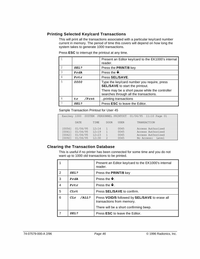
74-07579-000-A 2/96 Page 46 © 1996 Radionics, Inc.
Printing Selected Key/card TransactionsThis will print all the transactions associated with a particular key/card numbercurrent in memory. The period of time this covers will depend on how long thesystem takes to generate 1000 transactions.
Press ESC to interrupt the printout at any time.
1 Present an Editor key/card to the EK1000’s internalreader.
2 SEL? Press the PRINT/8 key3 PrdA Press the .4 Prtr Press SEL/SAVE.5 0000 Type the key/card number you require, press
SEL/SAVE to start the printout.There may be a short pause while the controllersearches through all the transactions.
6 tr /Prnt ..printing transactions7 SEL? Press ESC to leave the Editor.
Sample Transaction Printout for User 45
Easikey 1000 SYSTEM PERSONNEL PRINTOUT 01/06/95 11:10 Page 01
DATE TIME DOOR USER TRANSACTION
[0056] 01/06/95 12:14 1 0045 Access Authorized[0061] 01/06/95 12:19 1 0045 Access Authorized[0062] 01/06/95 12:23 1 0045 Access Authorized[0092] 01/06/95 12:30 2 0045 No Access: Level
Clearing the Transaction DatabaseThis is useful if no printer has been connected for some time and you do notwant up to 1000 old transactions to be printed.
1 Present an Editor key/card to the EK1000’s internalreader.
2 SEL? Press the PRINT/8 key
3 PrdA Press the .
4 Prtr Press the .
5 CLrt Press SEL/SAVE to confirm.
6 CLr /ALL? Press VOID/5 followed by SEL/SAVE to erase alltransactions from memory.
There will be a short confirming beep.
7 SEL? Press ESC to leave the Editor.

74-07579-000-A 2/96 Page 47 © 1996 Radionics, Inc.
Glossary
Anti-Tamper A means of detecting unauthorized disconnection of cables or removal ofcovers from security equipment.
Block Add If a large number of keyholders are to be entered into the database, it maybe more convenient to enter all the names, access groups, etc. first, thento assign the keys at a later date. The Personnel application includes aspecial ‘Block Add’ utility for this purpose.
Reader Channel A term used to describe the connections on a door controller for a singledoor - i.e. reader, locks and request to exit and door contact inputs.
Door Although this term is usually used to refer to a physical door at which areader is installed, it is useful to remember that sometimes each physicaldoor may have a reader installed on both sides - in this case it would bereferred to as two ‘doors’ in the context of the system.
Door Contact A device, usually a magnetic switch, which may be installed on a door tomonitor whether the door is open or closed.
Door Controller A microprocessor based unit from which up to two doors may becontrolled. The door controller reports to and is administered by the PC(s).The door controller makes the decision as to whether access is to beallowed.
Door Open Time If a door has a means of monitoring its state (closed or open) installed,then it is possible to configure the system to produce a transaction if thedoor is held open beyond a specified time.
Fail Safe / Fail Secure These terms are used to describe the two common types of locksavailable.
Fail Safe locks (also sometimes called ‘Power to Lock’) require apermanent supply to keep the door locked. This type of lock wouldnormally be used if safety was most important - i.e. in the event ofequipment failure the door would become unlocked.
Fail Secure locks (also called ‘Power to Unlock’) require power to unlockthe door.
Key/card An electronic identification device containing a unique code. This device isheld near to a Readykey reader to allow the code to be read, the doorcontroller then decides whether to release the lock.

74-07579-000-A 2/96 Page 48 © 1996 Radionics, Inc.
Lock Time The time that a door will be unlocked following a valid key/card beingpresented at a reader or a request to exit button being pressed. Note: thatthis time may be shortened if a door contact is installed and the door opensand re-closes before the lock time expires.
PIN Reader / PINNumber
A K2001-P PIN reader is a special type of Readykey reader which iscommonly used where an additional level of security is required. To gainaccess through a door, the keyholder must present their key, followed bytyping their 4-digit number. The PIN number is derived from the key codeand cannot be changed.
Reader A device installed adjacent to a door, which reads the stored code when akey/card is held close to it by a keyholder, and transmits to the doorcontroller. The reader also incorporates an ‘Access Authorized’ LED.
Report A printed list of information about a part or all of the system.
Request To Exit A N.O. switch, normally mounted on the secure side of the door allows exitfrom the area, without need for a key to be presented. Operation of thisswitch generates a ‘Request to Exit’ transaction.
Time Period A means of defining a limited time during which access may be controlled.Consists of a start time, end time, and one or more days.
Time Profile A group of up to three Time Periods, which may be assigned to an accessgroup to restrict a keyholders access to within the defined time limits. Mayalso be assigned to a door to unlock the door during the defined time.
Transaction Any event that occurs on an Easikey system is called a transaction. Alltransactions which originate from a door controller are reported to theprinter.
Unauthorized Access A special kind of alarm transaction which occurs when a door is openedwithout a valid key being presented to the reader, or the request to exitswitch being pressed.

74-07579-000-A 2/96 Page 49 © 1996 Radionics, Inc.
Power Input
AC Terminals 34 and 3616.5 VAC or 24 VDC
Battery Terminals 32 and 33One or two D126 12 VDC 7 AhBatteries. If using two batteries, useD122 Dual Battery Harness
Power Output
Lock12 VDC @ 1 Amp Continuous
Environmental
Temperature32º - 122º F
Relative Humidity85% Non-condensing
DoorsConnect up to two doors
Optional Anti passback
Optional Channel Interlock
Optional set / reset
UsersAssign up to 1000 key/cards to thesystem
Transaction BufferUp to 1000 events stored for printing
Printer OutputFive-wire Serial Communication
Time ProfilesAssign up to eight Time Profiles tousers or doors
EnclosuresD7103
D8103 with a D7102 mounting skirt
EK1000 PlusOptional Door Contact Monitoring
Optional Alarm Relay
Specifications

74-07579-000-A 2/96 Page 50 © 1996 Radionics, Inc.
Notes

O&I Menu
Documents by Type Menu
Documents by Product Menu
Main Menu