Embed Size (px)
Citation preview
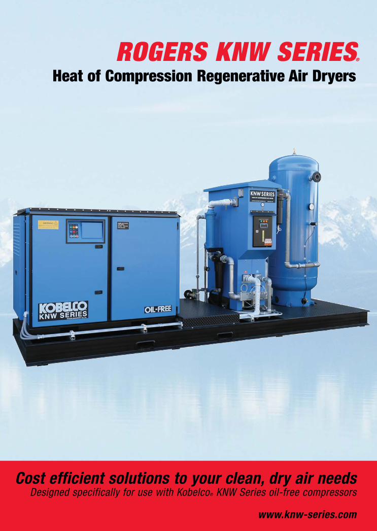
Heat of Compression Regenerative Air DryersROGERS KNW SERIES®
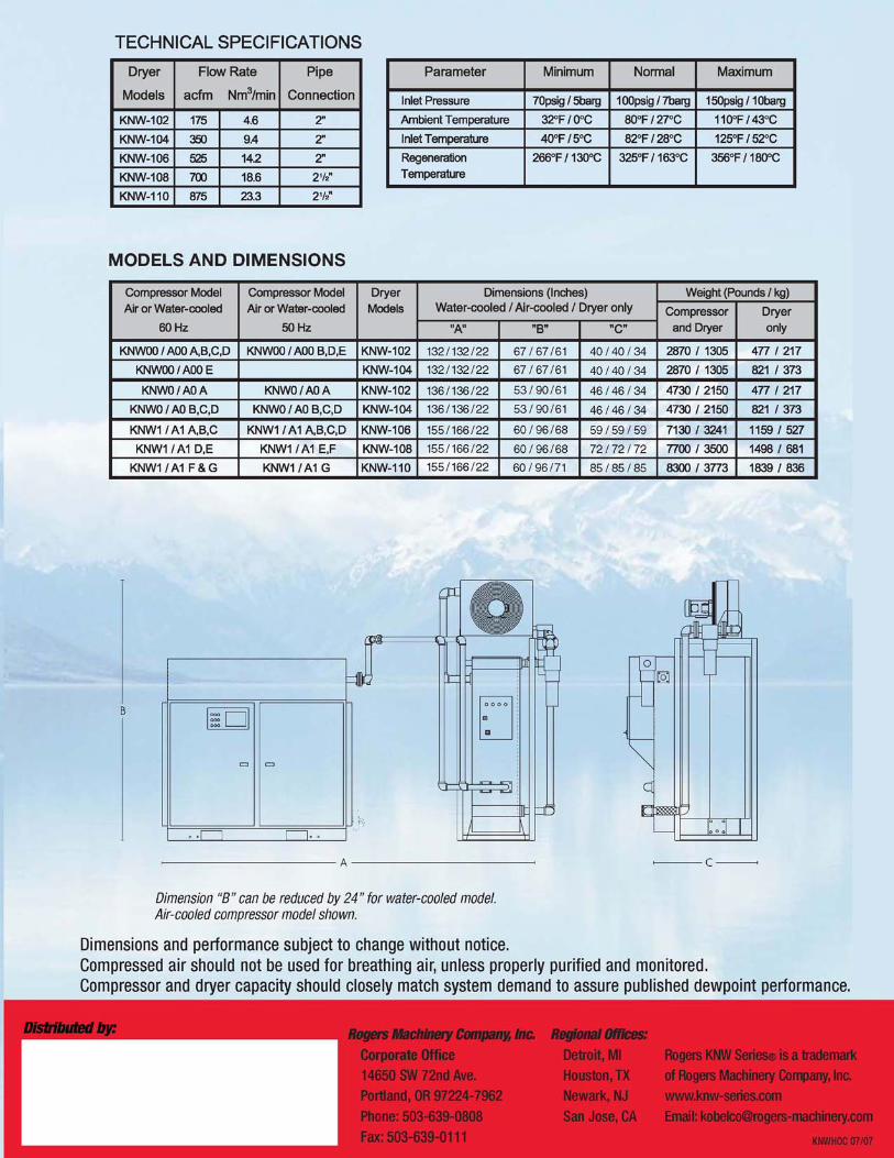
Dimension “B” can be reduced by 24” for water-cooled model.Air-cooled compressor model shown.
Rogers Machinery Company, Inc.Corporate Office14650 SW 72nd Ave.Portland, OR 97224-7962Phone: 503-639-0808Fax: 503-639-0111
Distributed by: Regional Offices:Detroit, MIHouston, TXNewark, NJSan Jose, CA
132 / 132 / 22 67 / 67 / 61
67 / 67 / 61
53 / 90 / 61
53 / 90 / 61
60 / 96 / 68
60 / 96 / 68
60 / 96 / 71
132 / 132 / 22
136 / 136 / 22
136 / 136 / 22
155 / 166 / 22
155 / 166 / 22
155 / 166 / 22
40 / 40 / 34
40 / 40 / 34
46 / 46 / 34
46 / 46 / 34
59 / 59 / 59
72 / 72 / 72
85 / 85 / 85
Cost efficient solutions to your clean, dry air needsDesigned specifically for use with Kobelco® KNW Series oil-free compressors
www.knw-series.com
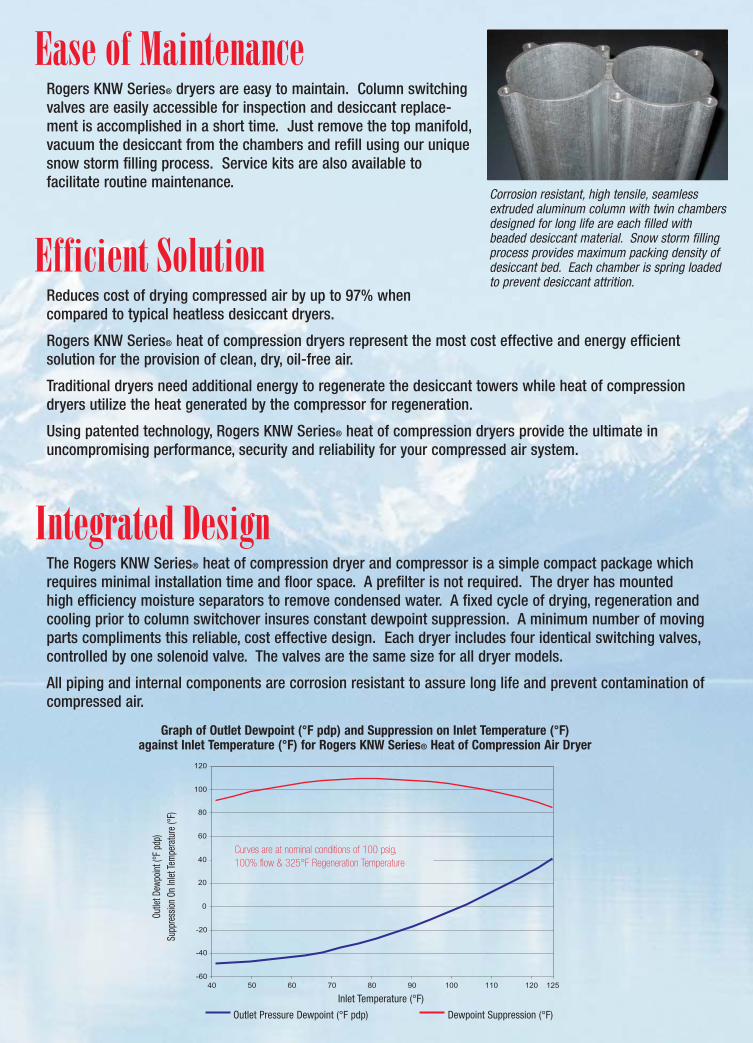
Ease of MaintenanceRogers KNW Series® dryers are easy to maintain. Column switchingvalves are easily accessible for inspection and desiccant replace-ment is accomplished in a short time. Just remove the top manifold,vacuum the desiccant from the chambers and refill using our uniquesnow storm filling process. Service kits are also available to facilitate routine maintenance.
Efficient SolutionReduces cost of drying compressed air by up to 97% when compared to typical heatless desiccant dryers.
Rogers KNW Series® heat of compression dryers represent the most cost effective and energy efficient solution for the provision of clean, dry, oil-free air.
Traditional dryers need additional energy to regenerate the desiccant towers while heat of compressiondryers utilize the heat generated by the compressor for regeneration.
Using patented technology, Rogers KNW Series® heat of compression dryers provide the ultimate in uncompromising performance, security and reliability for your compressed air system.
Integrated DesignThe Rogers KNW Series® heat of compression dryer and compressor is a simple compact package whichrequires minimal installation time and floor space. A prefilter is not required. The dryer has mounted high efficiency moisture separators to remove condensed water. A fixed cycle of drying, regeneration andcooling prior to column switchover insures constant dewpoint suppression. A minimum number of movingparts compliments this reliable, cost effective design. Each dryer includes four identical switching valves, controlled by one solenoid valve. The valves are the same size for all dryer models.
All piping and internal components are corrosion resistant to assure long life and prevent contamination ofcompressed air.
Corrosion resistant, high tensile, seamlessextruded aluminum column with twin chambersdesigned for long life are each filled with beaded desiccant material. Snow storm fillingprocess provides maximum packing density ofdesiccant bed. Each chamber is spring loadedto prevent desiccant attrition.
-60
-40
-20
0
20
40
60
80
100
120
40 50 60 70 80 90 100 110 120 125
Graph of Outlet Dewpoint (°F pdp) and Suppression on Inlet Temperature (°F) against Inlet Temperature (°F) for Rogers KNW Series® Heat of Compression Air Dryer
Curves are at nominal conditions of 100 psig, 100% flow & 325°F Regeneration Temperature
Outlet Pressure Dewpoint (°F pdp) Dewpoint Suppression (°F)
Inlet Temperature (°F)
Outle
t Dew
point
(°F
pdp)
Su
ppre
ssion
On
Inlet
Tem
pera
ture
(°F)
Rogers KNW Series® is a trademark of Rogers Machinery Company, Inc.www.knw-series.comEmail: [email protected]
KNWHOC 07/07
MODELS AND DIMENSIONS
Dimensions and performance subject to change without notice. Compressed air should not be used for breathing air, unless properly purified and monitored.Compressor and dryer capacity should closely match system demand to assure published dewpoint performance.
Regenerative HeatingFigure 1 shows the air flow path through the dryer with column A undergoing regeneration heatingand column B drying the air. Hot unsaturated regeneration air flows into the dryer’s hot inlet asselected by the inlet selector valve [V4]. The addition of cooled air, by the temp control solenoid, limitsthe temperature of regeneration air to a maximum of 350°F at T1 if necessary. The temp balancevalve equalizes pressures of the hot air and the cooled air streams, controlling the regen temperature.The regen air enters the bottom manifold of the column undergoing regeneration via the columnselection valve [V1]. The regeneration air then flows through the desiccant column, stripping theadsorbed moisture from the desiccant, and exits the column via the top manifold.
After exiting the top manifold at the outlet valve [V2], the regeneration air flows through the dryeraftercooler, which cools the regeneration air, causing most of the water vapor to condense. The condensed water is then removed from the compressed air by a high efficiency moisture separatorand a zero air loss drain.
The compressed air, which is saturated,enters the bottom manifold of the column B via the inlet valve [V3]. Thecompressed air then flows upwardthrough the column and the watervapor held within the compressed air is adsorbed by the desiccant. The nowdried compressed air exits the column,via the top manifold, at the outlet valve[V4], passes through the afterfilter andenters the plant compressed air distribution system.
Regenerative CoolingFigure 2 shows the air flow path through the dryer with column A undergoing regeneration cooling andcolumn B drying the air. The cooling cycle prevents dewpoint spikes at column switchover. The compressoraftercooler cools the regeneration air at T1 to 15°F above cooling media temperature. This cool and saturated regeneration air flows into dryer’s Cold Inlet as selected by the Hot/Cold inlet selector valve [V4].
The cooled regen air then enters the bottom manifold of the column undergoingregeneration cooling via column selectionvalve [V1]. The regeneration air flowsthrough the desiccant, stripping the heatfrom the desiccant and exits the columnvia the top manifold at the outlet valve[V2]. The water vapor is not adsorbed fromthe cool regeneration air as the desiccantis too hot to efficiently adsorb water vapor.
Once regeneration cooling is complete, the air flow path is reversed, with columnB undergoing regeneration heating thencooling, and column A drying the compressed air.
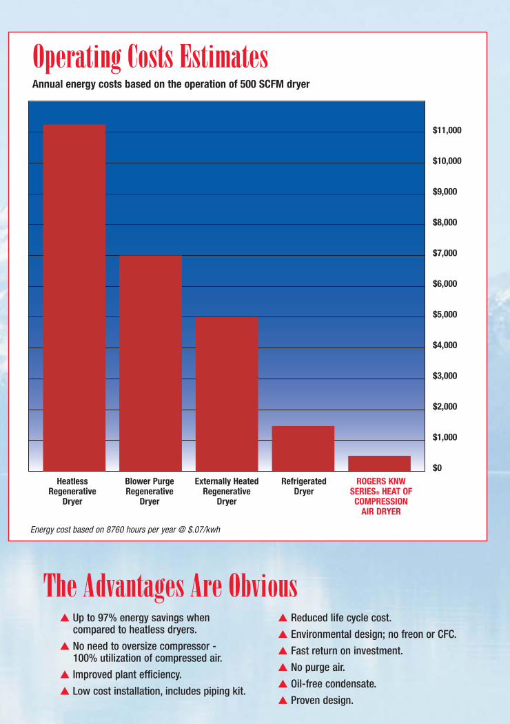
Operating Costs EstimatesAnnual energy costs based on the operation of 500 SCFM dryer
$11,000
$10,000
$9,000
$8,000
$7,000
$6,000
$5,000
$4,000
$3,000
$2,000
$1,000
$0Heatless
RegenerativeDryer
Blower PurgeRegenerative
Dryer
Externally HeatedRegenerative
Dryer
Refrigerated Dryer
ROGERS KNWSERIES® HEAT OF
COMPRESSION AIR DRYER
Energy cost based on 8760 hours per year @ $.07/kwh
The Advantages Are Obvious▲ Up to 97% energy savings when
compared to heatless dryers.
▲ No need to oversize compressor -100% utilization of compressed air.
▲ Improved plant efficiency.
▲ Low cost installation, includes piping kit.
▲ Reduced life cycle cost.
▲ Environmental design; no freon or CFC.
▲ Fast return on investment.
▲ No purge air.
▲ Oil-free condensate.
▲ Proven design.
Figure 1
Figure 2
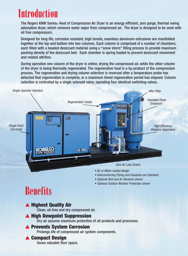
IntroductionThe Rogers KNW Series® Heat of Compression Air Dryer is an energy efficient, zero purge, thermal swingadsorption dryer, which removes water vapor from compressed air. The dryer is designed to be used withoil free compressors.
Designed for long life, corrosion resistant, high tensile, seamless aluminum extrusions are manifoldedtogether at the top and bottom into two columns. Each column is comprised of a number of chambers,each filled with a beaded desiccant material using a “snow storm” filling process to provide maximumpacking density of the desiccant bed. Each chamber is spring loaded to prevent desiccant movement and related attrition.
During operation one column of the dryer is online, drying the compressed air, while the other column of the dryer is being thermally regenerated. The regeneration heat is a by-product of the compressionprocess. The regeneration and drying column selection is reversed after a temperature probe has detected that regeneration is complete, or a maximum timed regeneration period has elapsed. Columnselection is controlled by a single solenoid valve, operating four identical switching valves.
Benefits▲ Highest Quality Air
Clean, oil-free and dry compressed air.
▲ High Dewpoint SuppressionDry air assures maximum protection of all products and processes.
▲ Prevents System CorrosionProlongs life of compressed air system components.
▲ Compact DesignSaves valuable floor space.
• Air or Water-cooled design• Interconnecting Piping and Insulation are Standard• Optional Skid and Air Receiver shown• Optional Outdoor Weather Protection shown
Regeneration Cooler
After Filter
Zero Air Loss Drains
High EfficiencyMoisture Separators
Insulated DryerEnclosure
Single Operator Interface
Single PointElectrical
Regenerative HeatingFigure 1 shows the air flow path through the dryer with column A undergoing regeneration heatingand column B drying the air. Hot unsaturated regeneration air flows into the dryer’s hot inlet asselected by the inlet selector valve [V4]. The addition of cooled air, by the temp control solenoid, limitsthe temperature of regeneration air to a maximum of 350°F at T1 if necessary. The temp balancevalve equalizes pressures of the hot air and the cooled air streams, controlling the regen temperature.The regen air enters the bottom manifold of the column undergoing regeneration via the columnselection valve [V1]. The regeneration air then flows through the desiccant column, stripping theadsorbed moisture from the desiccant, and exits the column via the top manifold.
After exiting the top manifold at the outlet valve [V2], the regeneration air flows through the dryeraftercooler, which cools the regeneration air, causing most of the water vapor to condense. The condensed water is then removed from the compressed air by a high efficiency moisture separatorand a zero air loss drain.
The compressed air, which is saturated,enters the bottom manifold of the column B via the inlet valve [V3]. Thecompressed air then flows upwardthrough the column and the watervapor held within the compressed air is adsorbed by the desiccant. The nowdried compressed air exits the column,via the top manifold, at the outlet valve[V4], passes through the afterfilter andenters the plant compressed air distribution system.
Regenerative CoolingFigure 2 shows the air flow path through the dryer with column A undergoing regeneration cooling andcolumn B drying the air. The cooling cycle prevents dewpoint spikes at column switchover. The compressoraftercooler cools the regeneration air at T1 to 15°F above cooling media temperature. This cool and saturated regeneration air flows into dryer’s Cold Inlet as selected by the Hot/Cold inlet selector valve [V4].
The cooled regen air then enters the bottom manifold of the column undergoingregeneration cooling via column selectionvalve [V1]. The regeneration air flowsthrough the desiccant, stripping the heatfrom the desiccant and exits the columnvia the top manifold at the outlet valve[V2]. The water vapor is not adsorbed fromthe cool regeneration air as the desiccantis too hot to efficiently adsorb water vapor.
Once regeneration cooling is complete, the air flow path is reversed, with columnB undergoing regeneration heating thencooling, and column A drying the compressed air.
Operating Costs EstimatesAnnual energy costs based on the operation of 500 SCFM dryer
$11,000
$10,000
$9,000
$8,000
$7,000
$6,000
$5,000
$4,000
$3,000
$2,000
$1,000
$0Heatless
RegenerativeDryer
Blower PurgeRegenerative
Dryer
Externally HeatedRegenerative
Dryer
Refrigerated Dryer
ROGERS KNWSERIES® HEAT OF
COMPRESSION AIR DRYER
Energy cost based on 8760 hours per year @ $.07/kwh
The Advantages Are Obvious▲ Up to 97% energy savings when
compared to heatless dryers.
▲ No need to oversize compressor -100% utilization of compressed air.
▲ Improved plant efficiency.
▲ Low cost installation, includes piping kit.
▲ Reduced life cycle cost.
▲ Environmental design; no freon or CFC.
▲ Fast return on investment.
▲ No purge air.
▲ Oil-free condensate.
▲ Proven design.
Figure 1
Figure 2
IntroductionThe Rogers KNW Series® Heat of Compression Air Dryer is an energy efficient, zero purge, thermal swingadsorption dryer, which removes water vapor from compressed air. The dryer is designed to be used withoil free compressors.
Designed for long life, corrosion resistant, high tensile, seamless aluminum extrusions are manifoldedtogether at the top and bottom into two columns. Each column is comprised of a number of chambers,each filled with a beaded desiccant material using a “snow storm” filling process to provide maximumpacking density of the desiccant bed. Each chamber is spring loaded to prevent desiccant movement and related attrition.
During operation one column of the dryer is online, drying the compressed air, while the other column of the dryer is being thermally regenerated. The regeneration heat is a by-product of the compressionprocess. The regeneration and drying column selection is reversed after a temperature probe has detected that regeneration is complete, or a maximum timed regeneration period has elapsed. Columnselection is controlled by a single solenoid valve, operating four identical switching valves.
Benefits▲ Highest Quality Air
Clean, oil-free and dry compressed air.
▲ High Dewpoint SuppressionDry air assures maximum protection of all products and processes.
▲ Prevents System CorrosionProlongs life of compressed air system components.
▲ Compact DesignSaves valuable floor space.
• Air or Water-cooled design• Interconnecting Piping and Insulation are Standard• Optional Skid and Air Receiver shown• Optional Outdoor Weather Protection shown
Regeneration Cooler
After Filter
Zero Air Loss Drains
High EfficiencyMoisture Separators
Insulated DryerEnclosure
Single Operator Interface
Single PointElectrical
Heat of Compression Regenerative Air DryersROGERS KNW SERIES®
Dimension “B” can be reduced by 24” for water-cooled model.Air-cooled compressor model shown.
Rogers Machinery Company, Inc.Corporate Office14650 SW 72nd Ave.Portland, OR 97224-7962Phone: 503-639-0808Fax: 503-639-0111
Distributed by: Regional Offices:Detroit, MIHouston, TXNewark, NJSan Jose, CA
132 / 132 / 22 67 / 67 / 61
67 / 67 / 61
53 / 90 / 61
53 / 90 / 61
60 / 96 / 68
60 / 96 / 68
60 / 96 / 71
132 / 132 / 22
136 / 136 / 22
136 / 136 / 22
155 / 166 / 22
155 / 166 / 22
155 / 166 / 22
40 / 40 / 34
40 / 40 / 34
46 / 46 / 34
46 / 46 / 34
59 / 59 / 59
72 / 72 / 72
85 / 85 / 85
Cost efficient solutions to your clean, dry air needsDesigned specifically for use with Kobelco® KNW Series oil-free compressors
www.knw-series.com
Ease of MaintenanceRogers KNW Series® dryers are easy to maintain. Column switchingvalves are easily accessible for inspection and desiccant replace-ment is accomplished in a short time. Just remove the top manifold,vacuum the desiccant from the chambers and refill using our uniquesnow storm filling process. Service kits are also available to facilitate routine maintenance.
Efficient SolutionReduces cost of drying compressed air by up to 97% when compared to typical heatless desiccant dryers.
Rogers KNW Series® heat of compression dryers represent the most cost effective and energy efficient solution for the provision of clean, dry, oil-free air.
Traditional dryers need additional energy to regenerate the desiccant towers while heat of compressiondryers utilize the heat generated by the compressor for regeneration.
Using patented technology, Rogers KNW Series® heat of compression dryers provide the ultimate in uncompromising performance, security and reliability for your compressed air system.
Integrated DesignThe Rogers KNW Series® heat of compression dryer and compressor is a simple compact package whichrequires minimal installation time and floor space. A prefilter is not required. The dryer has mounted high efficiency moisture separators to remove condensed water. A fixed cycle of drying, regeneration andcooling prior to column switchover insures constant dewpoint suppression. A minimum number of movingparts compliments this reliable, cost effective design. Each dryer includes four identical switching valves, controlled by one solenoid valve. The valves are the same size for all dryer models.
All piping and internal components are corrosion resistant to assure long life and prevent contamination ofcompressed air.
Corrosion resistant, high tensile, seamlessextruded aluminum column with twin chambersdesigned for long life are each filled with beaded desiccant material. Snow storm fillingprocess provides maximum packing density ofdesiccant bed. Each chamber is spring loadedto prevent desiccant attrition.
-60
-40
-20
0
20
40
60
80
100
120
40 50 60 70 80 90 100 110 120 125
Graph of Outlet Dewpoint (°F pdp) and Suppression on Inlet Temperature (°F) against Inlet Temperature (°F) for Rogers KNW Series® Heat of Compression Air Dryer
Curves are at nominal conditions of 100 psig, 100% flow & 325°F Regeneration Temperature
Outlet Pressure Dewpoint (°F pdp) Dewpoint Suppression (°F)
Inlet Temperature (°F)
Outle
t Dew
point
(°F
pdp)
Su
ppre
ssion
On
Inlet
Tem
pera
ture
(°F)
Rogers KNW Series® is a trademark of Rogers Machinery Company, Inc.www.knw-series.comEmail: [email protected]
KNWHOC 07/07
MODELS AND DIMENSIONS
Dimensions and performance subject to change without notice. Compressed air should not be used for breathing air, unless properly purified and monitored.Compressor and dryer capacity should closely match system demand to assure published dewpoint performance.