Embed Size (px)
Citation preview
TCDS No. EASA.A.098 Scheibe powered sailplanes
Page 1 of 62 Date: 14 Jan 2016 Issue 11
EASA
TYPE-CERTIFICATE DATA SHEET
EASA.A.098
Scheibe powered sailplanes
Type Certificate Holder:
SCHEIBE-AIRCRAFT – GMBH Sudetenstraße 57/2,Flugplatz Heubach
D-73540 Heubach Deutschland
Models: SF 25 A SF 25 B SF 25 C SF 25 D SF 25 E SF 25 K SF 28 A “Tandem-Falke” SF 36 A SF 36 R
Issue 11, 14 Jan 2016
TCDS No. EASA.A.098 Scheibe powered sailplanes Content
Page 2 of 62 Date: 14 Jan 2016 Issue 11
Content Content ...................................................................................................................... 2
Section A: SF 25 A .................................................................................................... 4
A.I. General ......................................................................................................................................... 4
A.II. Certification Basis ........................................................................................................................ 4
A.III. Technical Characteristics and Operational Limitations .............................................................. 5
A.IV. Operating and Service Instructions ............................................................................................ 8
A.V. Notes ........................................................................................................................................... 8
Section B: SF 25 B ...................................................................................................10
B.I. General ....................................................................................................................................... 10
B.II. Certification Basis ...................................................................................................................... 10
B.III. Technical Characteristics and Operational Limitations ............................................................ 11
B.IV. Operating and Service Instructions .......................................................................................... 15
B.V. Notes ......................................................................................................................................... 16
Section C: SF 25 C ...................................................................................................18
C.I. General ....................................................................................................................................... 18
C.II. Certification Basis ...................................................................................................................... 18
C.III. Technical Characteristics and Operational Limitations ............................................................ 19
C.IV. Operating and Service Instructions .......................................................................................... 27
C.V. Notes ......................................................................................................................................... 30
Section D: SF 25 D ...................................................................................................34
D.I. General ....................................................................................................................................... 34
D.II. Certification Basis ...................................................................................................................... 34
D.III. Technical Characteristics and Operational Limitations ............................................................ 35
D.IV. Operating and Service Instructions .......................................................................................... 37
D.V. Notes ......................................................................................................................................... 37
Section E: SF 25 E ...................................................................................................38
E.I. General ....................................................................................................................................... 38
E.II. Certification Basis ...................................................................................................................... 38
E.III. Technical Characteristics and Operational Limitations ............................................................ 39
E.IV. Operating and Service Instructions .......................................................................................... 41
E.V. Notes ......................................................................................................................................... 42
Section F: SF 25 K ...................................................................................................43
F.I. General ....................................................................................................................................... 43
F.II. Certification Basis ...................................................................................................................... 43
F.III. Technical Characteristics and Operational Limitations ............................................................. 43
F.IV. Operating and Service Instructions .......................................................................................... 46
F.V. Notes ......................................................................................................................................... 46
Section G: SF 28 A “Tandem-Falke” ......................................................................47
A.I. General ....................................................................................................................................... 47
A.II. Certification Basis ...................................................................................................................... 47
A.III. Technical Characteristics and Operational Limitations ............................................................ 48
TCDS No. EASA.A.098 Scheibe powered sailplanes Content
Page 3 of 62 Date: 14 Jan 2016 Issue 11
A.IV. Operating and Service Instructions .......................................................................................... 50
A.V. Notes ......................................................................................................................................... 51
SECTION H: SF 36 A ................................................................................................52
A.I. General ....................................................................................................................................... 52
A.II. Certification Basis ...................................................................................................................... 52
A.III. Technical Characteristics and Operational Limitations ............................................................ 53
A.IV. Operating and Service Instructions .......................................................................................... 56
A.V. Notes ......................................................................................................................................... 57
SECTION I: SF 36 R .................................................................................................58
B.I. General ....................................................................................................................................... 58
B.II. Certification Basis ...................................................................................................................... 58
B.III. Technical Characteristics and Operational Limitations ............................................................ 59
B.IV. Operating and Service Instructions .......................................................................................... 61
B.V. Notes ......................................................................................................................................... 61
Administrative section ............................................................................................62
TCDS No. EASA.A.098 Scheibe powered sailplanes Section A: SF 25 A
Page 4 of 62 Date: 14 Jan 2016 Issue 11
Section A: SF 25 A
A.I. General Allgemeines
1. Data Sheet No.: Kennblatt-Nr.:
EASA.A.098
2. a) Type: (Muster) b) Variant: (Baureihe)
c) Salesname: (Verkaufsbezeichnung)
SF 25 SF 25 A “Motorfalke”
3. Airworthiness Category: Lufttüchtigkeitskategorie:
Powered Sailplane, LBA-note Nr. 10.05, Utility Motorsegler, LBA-Mitteilung Nr. 10.05 Utility
4. Manufacturer: Hersteller:
Scheibe Flugzeugbau GmbH 8060 Dachau, August Pfalz Str. 23
5. LBA Type Certification Date: Datum der LBA-Musterzulassung:
13 July 1965
6. This TCDS replaces LBA TCDS No. 653, Issue 24 Dieses Kennblatt ersetzt das LBA Kennblatt Nr. 653, Ausgabe 24
A.II. Certification Basis Zulassungsbasis
1. Certification Basis: Zulassungsbasis:
Defined by LBA Confirmation letter with certification standards, dated 07 July 1962. Bestätigungsschreiben mit Zulassungsbedingungen.
2. Airworthiness Requirements: Lufttüchtigkeitsforderungen:
LBA-note Nr. 10.05, “Temporary Guidelines for the Exami- nation and Certification of Powered Sailplanes”, Issue 08 January 1959. LBA-Mitteilung Nr. 10.05 “Vorläufige Richtlinien für die Prüfung und Zulassung von Motorseglern”, Ausgabe 08 Januar 1959.
3. Requirements elected to comply: Gewählte Forderungen:
None Keine
4. Special Conditions: Sonderforderungen:
None Keine
5. Exemptions: Ausnahmen:
None Keine
6. Equivalent Safety Findings: Nachweise gleichwertiger Sicherheit:
None Keine
7. Environmental Standards: Lärmschutzforderungen:
ICAO Annex 16, Volume I (for more details see EASA TCDSN A.098) ICAO Annex 16, Volume I (weitere Informationen in EASA TCDSN A.098)
TCDS No. EASA.A.098 Scheibe powered sailplanes Section A: SF 25 A
Page 5 of 62 Date: 14 Jan 2016 Issue 11
A.III. Technical Characteristics and Operational Limitations Technische Merkmale und Betriebsgrenzen
1. Type Design Definition: Musterdefinition:
Drawing list SF 25 A, PfL approved Zeichnungsliste für SF 25 A, PfL anerkannt
2. Description: Beschreibung:
Two-seat, shoulder-winged powered sailplane in metal wood construction, fixed central mainwheel, spoilers. Zweisitziger Schulterdecker in Gemischt-Bauweise, festes zentrales Hauptrad, Störklappen.
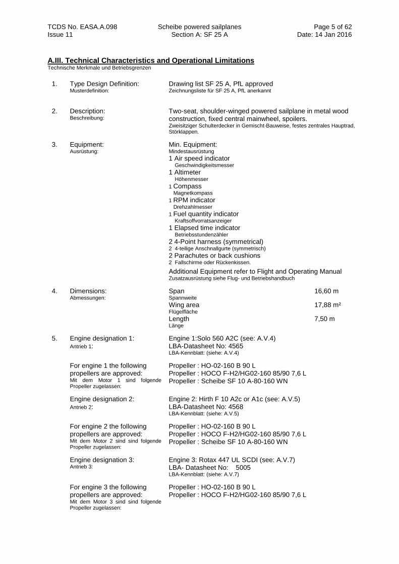
3. Equipment: Ausrüstung:
Min. Equipment: Mindestausrüstung
1 Air speed indicator Geschwindigkeitsmesser
1 Altimeter Höhenmesser
1 Compass
Magnetkompass
1 RPM indicator
Drehzahlmesser
1 Fuel quantity indicator
Kraftsoffvorratsanzeiger
1 Elapsed time indicator Betriebsstundenzähler
2 4-Point harness (symmetrical) 2 4-teilige Anschnallgurte (symmetrisch)
2 Parachutes or back cushions 2 Fallschirme oder Rückenkissen.
Additional Equipment refer to Flight and Operating Manual Zusatzausrüstung siehe Flug- und Betriebshandbuch
4. Dimensions: Abmessungen:
Span 16,60 m Spannweite
Wing area 17,88 m² Flügelfläche
Length 7,50 m Länge
5. Engine designation 1: Antrieb 1:
Engine 1:Solo 560 A2C (see: A.V.4) LBA-Datasheet No: 4565 LBA-Kennblatt: (siehe: A.V.4)
For engine 1 the following propellers are approved: Mit dem Motor 1 sind folgende Propeller zugelassen:
Propeller : HO-02-160 B 90 L Propeller : HOCO F-H2/HG02-160 85/90 7,6 L Propeller : Scheibe SF 10 A-80-160 WN
Engine designation 2: Antrieb 2:
Engine 2: Hirth F 10 A2c or A1c (see: A.V.5) LBA-Datasheet No: 4568 LBA-Kennblatt: (siehe: A.V.5)
For engine 2 the following propellers are approved: Mit dem Motor 2 sind sind folgende Propeller zugelassen:
Propeller : HO-02-160 B 90 L Propeller : HOCO F-H2/HG02-160 85/90 7,6 L Propeller : Scheibe SF 10 A-80-160 WN
Engine designation 3: Antrieb 3:
Engine 3: Rotax 447 UL SCDI (see: A.V.7) LBA- Datasheet No: 5005 LBA-Kennblatt: (siehe: A.V.7)
For engine 3 the following propellers are approved: Mit dem Motor 3 sind sind folgende Propeller zugelassen:
Propeller : HO-02-160 B 90 L Propeller : HOCO F-H2/HG02-160 85/90 7,6 L
TCDS No. EASA.A.098 Scheibe powered sailplanes Section A: SF 25 A
Page 6 of 62 Date: 14 Jan 2016 Issue 11
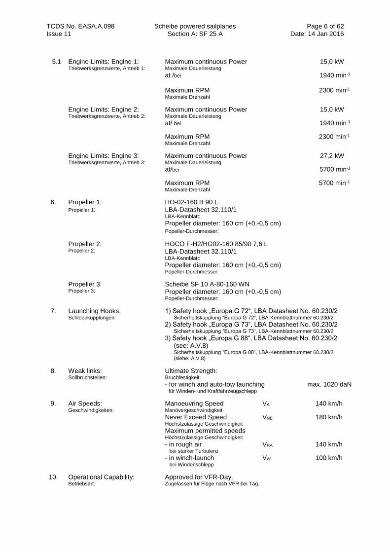
5.1 Engine Limits: Engine 1: Triebwerksgrenzwerte, Antrieb 1:
Maximum continuous Power 15,0 kW Maximale Dauerleistung
at /bei 1940 min-1
Maximum RPM 2300 min-1
Maximale Drehzahl
Engine Limits: Engine 2: Triebwerksgrenzwerte, Antrieb 2:
Maximum continuous Power 15,0 kW Maximale Dauerleistung
at/ bei 1940 min-1
Maximum RPM 2300 min-1
Maximale Drehzahl
Engine Limits: Engine 3: Triebwerksgrenzwerte, Antrieb 3:
Maximum continuous Power 27,2 kW Maximale Dauerleistung
at/bei 5700 min-1
Maximum RPM 5700 min-1
Maximale Drehzahl
6. Propeller 1: Propeller 1:
HO-02-160 B 90 L LBA-Datasheet 32.110/1 LBA-Kennblatt: Propeller diameter: 160 cm (+0,-0,5 cm) Popeller-Durchmesser:
Propeller 2: Propeller 2:
HOCO F-H2/HG02-160 85/90 7,6 L LBA-Datasheet 32.110/1 LBA-Kennblatt: Propeller diameter: 160 cm (+0,-0,5 cm) Popeller-Durchmesser:
Propeller 3: Propeller 3:
Scheibe SF 10 A-80-160 WN Propeller diameter: 160 cm (+0,-0,5 cm) Popeller-Durchmesser:
7. Launching Hooks: Schleppkupplungen:
1) Safety hook „Europa G 72“, LBA Datasheet No. 60.230/2
Sicherheitskupplung “Europa G 72“, LBA-Kennblattnummer 60.230/2 2) Safety hook „Europa G 73“, LBA Datasheet No. 60.230/2
Sicherheitskupplung “Europa G 73“, LBA-Kennblattnummer 60.230/2
3) Safety hook „Europa G 88“, LBA Datasheet No. 60.230/2
(see: A.V.8) Sicherheitskupplung “Europa G 88“, LBA-Kennblattnummer 60.230/2 (siehe: A.V.8)
8. Weak links: Sollbruchstellen:
Ultimate Strength: Bruchfestigkeit: - for winch and auto-tow launching max. 1020 daN für Winden- und Kraftfahrzeugschlepp
9. Air Speeds: Geschwindigkeiten:
Manoeuvring Speed VA 140 km/h Manövergeschwindigkeit Never Exceed Speed VNE 180 km/h Höchstzulässige Geschwindigkeit
Maximum permitted speeds Höchstzulässige Geschwindigkeit - in rough air VRA 140 km/h bei starker Turbulenz - in winch-launch VW 100 km/h bei Windenschlepp
10. Operational Capability: Betriebsart:
Approved for VFR-Day. Zugelassen für Flüge nach VFR bei Tag.
TCDS No. EASA.A.098 Scheibe powered sailplanes Section A: SF 25 A
Page 7 of 62 Date: 14 Jan 2016 Issue 11
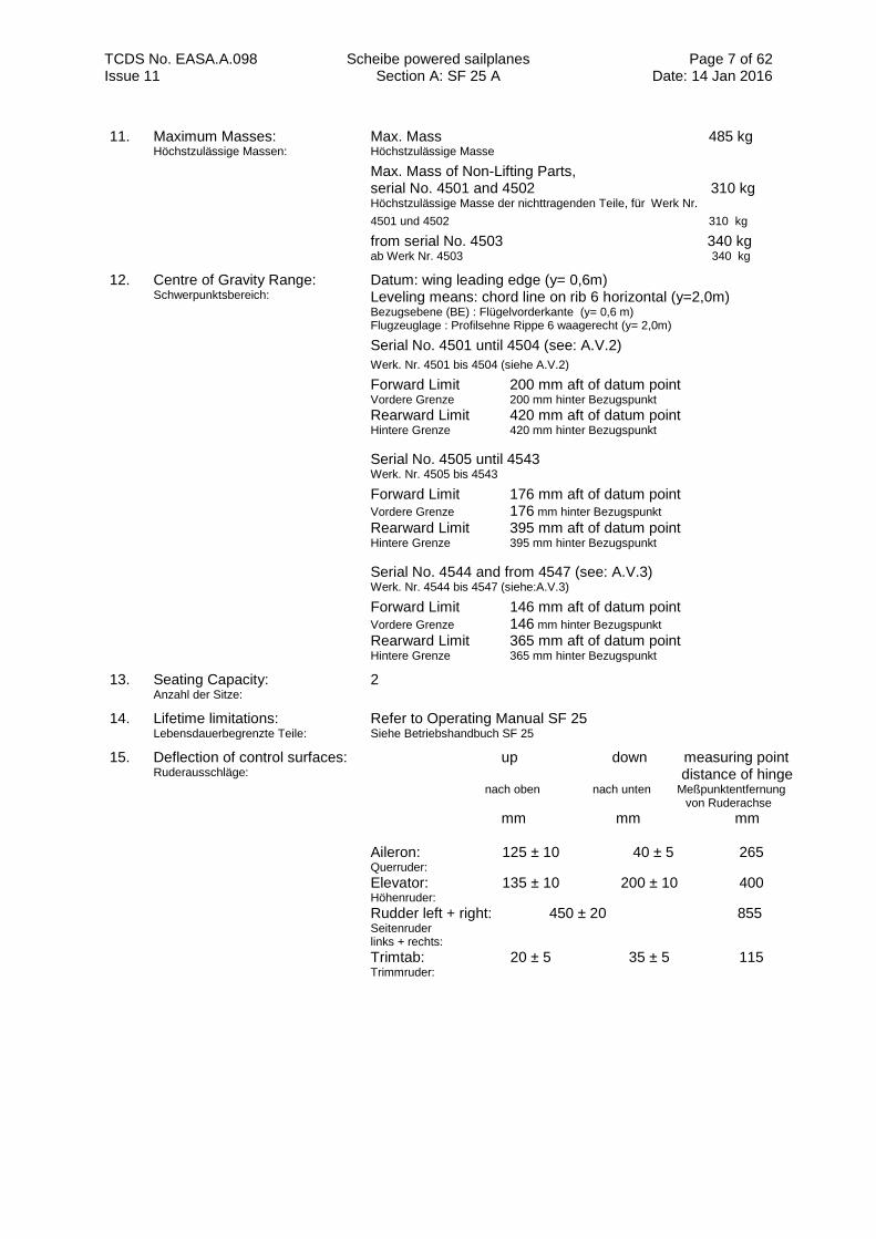
11. Maximum Masses: Höchstzulässige Massen:
Max. Mass 485 kg Höchstzulässige Masse
Max. Mass of Non-Lifting Parts, serial No. 4501 and 4502 310 kg Höchstzulässige Masse der nichttragenden Teile, für Werk Nr.
4501 und 4502 310 kg
from serial No. 4503 340 kg
ab Werk Nr. 4503 340 kg
12. Centre of Gravity Range: Schwerpunktsbereich:
Datum: wing leading edge (y= 0,6m) Leveling means: chord line on rib 6 horizontal (y=2,0m) Bezugsebene (BE) : Flügelvorderkante (y= 0,6 m) Flugzeuglage : Profilsehne Rippe 6 waagerecht (y= 2,0m)
Serial No. 4501 until 4504 (see: A.V.2)
Werk. Nr. 4501 bis 4504 (siehe A.V.2)
Forward Limit 200 mm aft of datum point Vordere Grenze 200 mm hinter Bezugspunkt Rearward Limit 420 mm aft of datum point Hintere Grenze 420 mm hinter Bezugspunkt
Serial No. 4505 until 4543 Werk. Nr. 4505 bis 4543
Forward Limit 176 mm aft of datum point Vordere Grenze 176 mm hinter Bezugspunkt Rearward Limit 395 mm aft of datum point Hintere Grenze 395 mm hinter Bezugspunkt
Serial No. 4544 and from 4547 (see: A.V.3) Werk. Nr. 4544 bis 4547 (siehe:A.V.3)
Forward Limit 146 mm aft of datum point Vordere Grenze 146 mm hinter Bezugspunkt Rearward Limit 365 mm aft of datum point Hintere Grenze 365 mm hinter Bezugspunkt
13. Seating Capacity: Anzahl der Sitze:
2
14. Lifetime limitations: Lebensdauerbegrenzte Teile:
Refer to Operating Manual SF 25
Siehe Betriebshandbuch SF 25
15. Deflection of control surfaces: Ruderausschläge:
up down measuring point distance of hinge nach oben nach unten Meßpunktentfernung von Ruderachse
mm mm mm Aileron: 125 ± 10 40 ± 5 265 Querruder:
Elevator: 135 ± 10 200 ± 10 400 Höhenruder:
Rudder left + right: 450 ± 20 855 Seitenruder links + rechts:
Trimtab: 20 ± 5 35 ± 5 115 Trimmruder:
TCDS No. EASA.A.098 Scheibe powered sailplanes Section A: SF 25 A
Page 8 of 62 Date: 14 Jan 2016 Issue 11
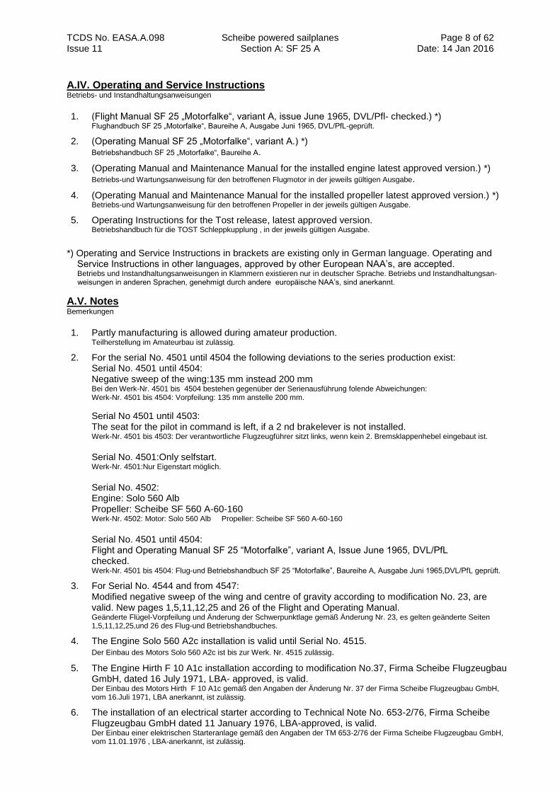
A.IV. Operating and Service Instructions Betriebs- und Instandhaltungsanweisungen
1. (Flight Manual SF 25 „Motorfalke“, variant A, issue June 1965, DVL/Pfl- checked.) *) Flughandbuch SF 25 „Motorfalke“, Baureihe A, Ausgabe Juni 1965, DVL/PfL-geprüft.
2. (Operating Manual SF 25 „Motorfalke“, variant A.) *) Betriebshandbuch SF 25 „Motorfalke“, Baureihe A.
3. (Operating Manual and Maintenance Manual for the installed engine latest approved version.) *) Betriebs-und Wartungsanweisung für den betroffenen Flugmotor in der jeweils gültigen Ausgabe.
4. (Operating Manual and Maintenance Manual for the installed propeller latest approved version.) *) Betriebs-und Wartungsanweisung für den betroffenen Propeller in der jeweils gültigen Ausgabe.
5. Operating Instructions for the Tost release, latest approved version. Betriebshandbuch für die TOST Schleppkupplung , in der jeweils gültigen Ausgabe.
*) Operating and Service Instructions in brackets are existing only in German language. Operating and Service Instructions in other languages, approved by other European NAA’s, are accepted. Betriebs und Instandhaltungsanweisungen in Klammern existieren nur in deutscher Sprache. Betriebs und Instandhaltungsan- weisungen in anderen Sprachen, genehmigt durch andere europäische NAA’s, sind anerkannt.
A.V. Notes Bemerkungen
1. Partly manufacturing is allowed during amateur production. Teilherstellung im Amateurbau ist zulässig.
2. For the serial No. 4501 until 4504 the following deviations to the series production exist: Serial No. 4501 until 4504: Negative sweep of the wing:135 mm instead 200 mm Bei den Werk-Nr. 4501 bis 4504 bestehen gegenüber der Serienausführung folende Abweichungen: Werk-Nr. 4501 bis 4504: Vorpfeilung: 135 mm anstelle 200 mm.
Serial No 4501 until 4503: The seat for the pilot in command is left, if a 2 nd brakelever is not installed. Werk-Nr. 4501 bis 4503: Der verantwortliche Flugzeugführer sitzt links, wenn kein 2. Bremsklappenhebel eingebaut ist.
Serial No. 4501:Only selfstart. Werk-Nr. 4501:Nur Eigenstart möglich.
Serial No. 4502: Engine: Solo 560 Alb Propeller: Scheibe SF 560 A-60-160 Werk-Nr. 4502: Motor: Solo 560 Alb Propeller: Scheibe SF 560 A-60-160 Serial No. 4501 until 4504: Flight and Operating Manual SF 25 “Motorfalke”, variant A, Issue June 1965, DVL/PfL checked. Werk-Nr. 4501 bis 4504: Flug-und Betriebshandbuch SF 25 “Motorfalke”, Baureihe A, Ausgabe Juni 1965,DVL/PfL geprüft.
3. For Serial No. 4544 and from 4547: Modified negative sweep of the wing and centre of gravity according to modification No. 23, are valid. New pages 1,5,11,12,25 and 26 of the Flight and Operating Manual. Geänderte Flügel-Vorpfeilung und Änderung der Schwerpunktlage gemäß Änderung Nr. 23, es gelten geänderte Seiten 1,5,11,12,25,und 26 des Flug-und Betriebshandbuches.
4. The Engine Solo 560 A2c installation is valid until Serial No. 4515. Der Einbau des Motors Solo 560 A2c ist bis zur Werk. Nr. 4515 zulässig.
5. The Engine Hirth F 10 A1c installation according to modification No.37, Firma Scheibe Flugzeugbau GmbH, dated 16 July 1971, LBA- approved, is valid. Der Einbau des Motors Hirth F 10 A1c gemäß den Angaben der Änderung Nr. 37 der Firma Scheibe Flugzeugbau GmbH, vom 16.Juli 1971, LBA anerkannt, ist zulässig.
6. The installation of an electrical starter according to Technical Note No. 653-2/76, Firma Scheibe Flugzeugbau GmbH dated 11 January 1976, LBA-approved, is valid. Der Einbau einer elektrischen Starteranlage gemäß den Angaben der TM 653-2/76 der Firma Scheibe Flugzeugbau GmbH, vom 11.01.1976 , LBA-anerkannt, ist zulässig.
TCDS No. EASA.A.098 Scheibe powered sailplanes
Page 9 of 62 Date: 14 Jan 2016 Issue 11
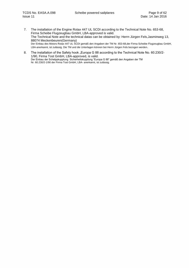
7. The installation of the Engine Rotax 447 UL SCDI according to the Technical Note No. 653-68, Firma Scheibe Flugzeugbau GmbH, LBA-approved is valid. The Technical Note and the technical datas can be obtained by: Herrn Jürgen Fels,Jasminweg 13, 88074 Meckenbeuren(Germany) Der Einbau des Motors Rotax 447 UL SCDI gemäß den Angaben der TM Nr. 653-68,der Firma Scheibe Flugzeugbau GmbH,
LBA-anerkannt, ist zulässig. Die TM und die Unterlagen können bei Herrn Jürgen Fels bezogen werden.
8. The installation of the Safety hook „Europa G 88 according to the Technical Note No. 60.230/2- 1/90, Firma Tost GmbH, LBA-approved, is valid. Der Einbau der Schelppkupplung Sicherheitskupplung “Europa G 88” gemäß den Angaben der TM Nr. 60.230/2-1/90 der Firma Tost GmbH, LBA- anerkannt, ist zulässig.
TCDS No. EASA.A.098 Scheibe powered sailplanes Section B: SF 25 B
Page 10 of 62 Date: 14 Jan 2016 Issue 11
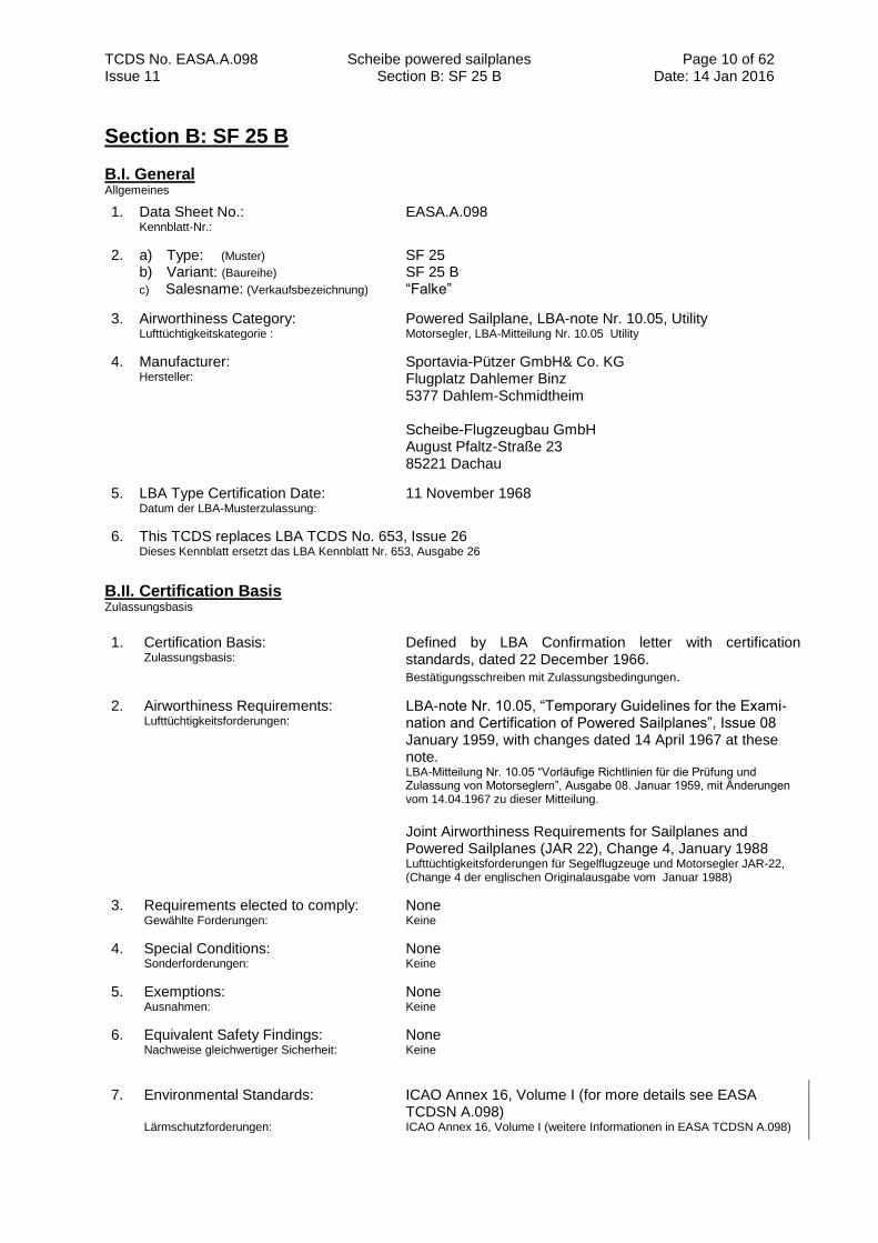
Section B: SF 25 B
B.I. General Allgemeines
1. Data Sheet No.: Kennblatt-Nr.:
EASA.A.098
2. a) Type: (Muster) b) Variant: (Baureihe)
c) Salesname: (Verkaufsbezeichnung)
SF 25 SF 25 B “Falke”
3. Airworthiness Category: Lufttüchtigkeitskategorie :
Powered Sailplane, LBA-note Nr. 10.05, Utility Motorsegler, LBA-Mitteilung Nr. 10.05 Utility
4. Manufacturer: Hersteller:
Sportavia-Pützer GmbH& Co. KG Flugplatz Dahlemer Binz 5377 Dahlem-Schmidtheim Scheibe-Flugzeugbau GmbH August Pfaltz-Straße 23 85221 Dachau
5. LBA Type Certification Date: Datum der LBA-Musterzulassung:
11 November 1968
6. This TCDS replaces LBA TCDS No. 653, Issue 26 Dieses Kennblatt ersetzt das LBA Kennblatt Nr. 653, Ausgabe 26
B.II. Certification Basis Zulassungsbasis
1. Certification Basis: Zulassungsbasis:
Defined by LBA Confirmation letter with certification standards, dated 22 December 1966. Bestätigungsschreiben mit Zulassungsbedingungen.
2. Airworthiness Requirements: Lufttüchtigkeitsforderungen:
LBA-note Nr. 10.05, “Temporary Guidelines for the Exami- nation and Certification of Powered Sailplanes”, Issue 08 January 1959, with changes dated 14 April 1967 at these note. LBA-Mitteilung Nr. 10.05 “Vorläufige Richtlinien für die Prüfung und Zulassung von Motorseglern”, Ausgabe 08. Januar 1959, mit Änderungen vom 14.04.1967 zu dieser Mitteilung. Joint Airworthiness Requirements for Sailplanes and Powered Sailplanes (JAR 22), Change 4, January 1988 Lufttüchtigkeitsforderungen für Segelflugzeuge und Motorsegler JAR-22, (Change 4 der englischen Originalausgabe vom Januar 1988)
3. Requirements elected to comply: Gewählte Forderungen:
None Keine
4. Special Conditions: Sonderforderungen:
None Keine
5. Exemptions: Ausnahmen:
None Keine
6. Equivalent Safety Findings: Nachweise gleichwertiger Sicherheit:
None Keine
7. Environmental Standards: Lärmschutzforderungen:
ICAO Annex 16, Volume I (for more details see EASA TCDSN A.098) ICAO Annex 16, Volume I (weitere Informationen in EASA TCDSN A.098)
TCDS No. EASA.A.098 Scheibe powered sailplanes Section B: SF 25 B
Page 11 of 62 Date: 14 Jan 2016 Issue 11
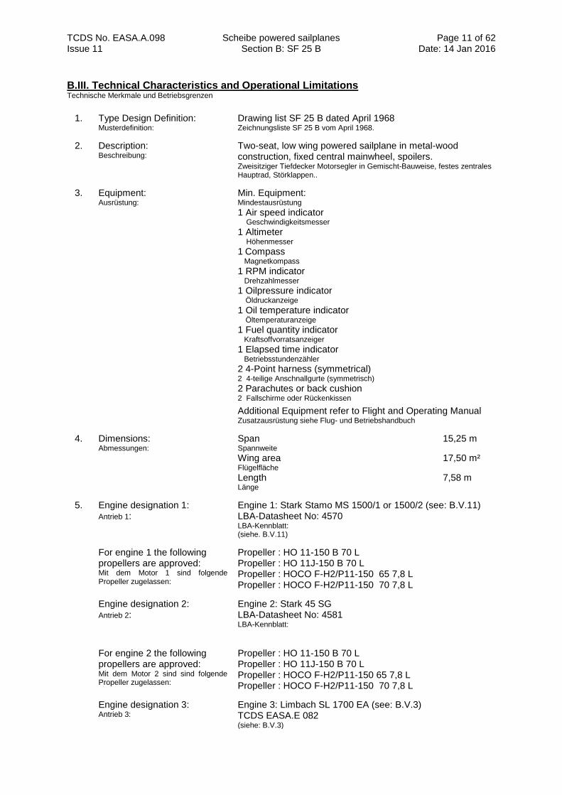
B.III. Technical Characteristics and Operational Limitations Technische Merkmale und Betriebsgrenzen
1. Type Design Definition: Musterdefinition:
Drawing list SF 25 B dated April 1968 Zeichnungsliste SF 25 B vom April 1968.
2. Description: Beschreibung:
Two-seat, low wing powered sailplane in metal-wood construction, fixed central mainwheel, spoilers. Zweisitziger Tiefdecker Motorsegler in Gemischt-Bauweise, festes zentrales Hauptrad, Störklappen..
3. Equipment: Ausrüstung:
Min. Equipment: Mindestausrüstung
1 Air speed indicator Geschwindigkeitsmesser
1 Altimeter Höhenmesser
1 Compass
Magnetkompass
1 RPM indicator Drehzahlmesser
1 Oilpressure indicator Öldruckanzeige
1 Oil temperature indicator Öltemperaturanzeige
1 Fuel quantity indicator Kraftsoffvorratsanzeiger
1 Elapsed time indicator Betriebsstundenzähler
2 4-Point harness (symmetrical) 2 4-teilige Anschnallgurte (symmetrisch)
2 Parachutes or back cushion 2 Fallschirme oder Rückenkissen
Additional Equipment refer to Flight and Operating Manual Zusatzausrüstung siehe Flug- und Betriebshandbuch
4. Dimensions: Abmessungen:
Span 15,25 m Spannweite
Wing area 17,50 m² Flügelfläche
Length 7,58 m Länge
5. Engine designation 1: Antrieb 1:
Engine 1: Stark Stamo MS 1500/1 or 1500/2 (see: B.V.11) LBA-Datasheet No: 4570 LBA-Kennblatt: (siehe. B.V.11)
For engine 1 the following propellers are approved: Mit dem Motor 1 sind folgende Propeller zugelassen:
Propeller : HO 11-150 B 70 L Propeller : HO 11J-150 B 70 L Propeller : HOCO F-H2/P11-150 65 7,8 L Propeller : HOCO F-H2/P11-150 70 7,8 L
Engine designation 2: Antrieb 2:
Engine 2: Stark 45 SG LBA-Datasheet No: 4581 LBA-Kennblatt:
For engine 2 the following propellers are approved: Mit dem Motor 2 sind sind folgende Propeller zugelassen:
Propeller : HO 11-150 B 70 L Propeller : HO 11J-150 B 70 L Propeller : HOCO F-H2/P11-150 65 7,8 L Propeller : HOCO F-H2/P11-150 70 7,8 L
Engine designation 3: Antrieb 3:
Engine 3: Limbach SL 1700 EA (see: B.V.3) TCDS EASA.E 082
(siehe: B.V.3)
TCDS No. EASA.A.098 Scheibe powered sailplanes Section B: SF 25 B
Page 12 of 62 Date: 14 Jan 2016 Issue 11
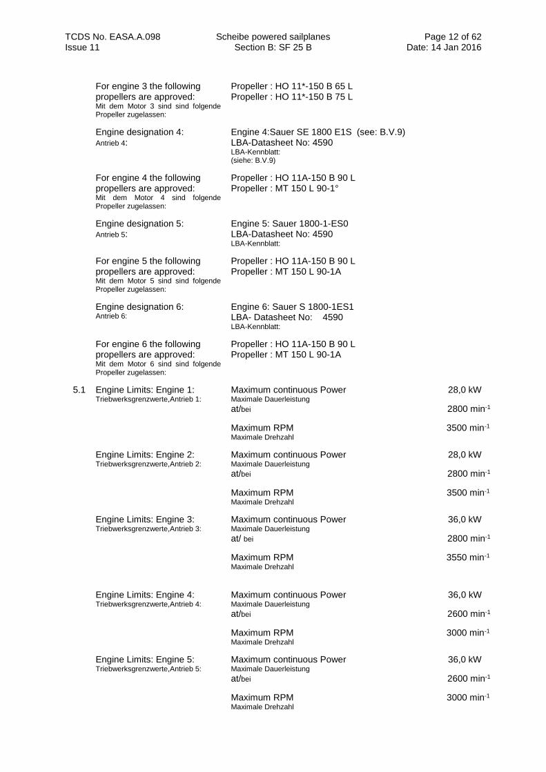
For engine 3 the following propellers are approved: Mit dem Motor 3 sind sind folgende Propeller zugelassen:
Propeller : HO 11*-150 B 65 L Propeller : HO 11*-150 B 75 L
Engine designation 4: Antrieb 4:
Engine 4:Sauer SE 1800 E1S (see: B.V.9) LBA-Datasheet No: 4590 LBA-Kennblatt: (siehe: B.V.9)
For engine 4 the following propellers are approved: Mit dem Motor 4 sind folgende Propeller zugelassen:
Propeller : HO 11A-150 B 90 L Propeller : MT 150 L 90-1°
Engine designation 5: Antrieb 5:
Engine 5: Sauer 1800-1-ES0 LBA-Datasheet No: 4590 LBA-Kennblatt:
For engine 5 the following propellers are approved: Mit dem Motor 5 sind sind folgende Propeller zugelassen:
Propeller : HO 11A-150 B 90 L Propeller : MT 150 L 90-1A
Engine designation 6: Antrieb 6:
Engine 6: Sauer S 1800-1ES1 LBA- Datasheet No: 4590 LBA-Kennblatt:
For engine 6 the following propellers are approved: Mit dem Motor 6 sind sind folgende Propeller zugelassen:
Propeller : HO 11A-150 B 90 L Propeller : MT 150 L 90-1A
5.1 Engine Limits: Engine 1: Triebwerksgrenzwerte,Antrieb 1:
Maximum continuous Power 28,0 kW Maximale Dauerleistung
at/bei 2800 min-1
Maximum RPM 3500 min-1
Maximale Drehzahl
Engine Limits: Engine 2: Triebwerksgrenzwerte,Antrieb 2:
Maximum continuous Power 28,0 kW Maximale Dauerleistung
at/bei 2800 min-1
Maximum RPM 3500 min-1
Maximale Drehzahl
Engine Limits: Engine 3: Triebwerksgrenzwerte,Antrieb 3:
Maximum continuous Power 36,0 kW Maximale Dauerleistung
at/ bei 2800 min-1
Maximum RPM 3550 min-1
Maximale Drehzahl
Engine Limits: Engine 4: Triebwerksgrenzwerte,Antrieb 4:
Maximum continuous Power 36,0 kW Maximale Dauerleistung
at/bei 2600 min-1
Maximum RPM 3000 min-1
Maximale Drehzahl
Engine Limits: Engine 5: Triebwerksgrenzwerte,Antrieb 5:
Maximum continuous Power 36,0 kW Maximale Dauerleistung
at/bei 2600 min-1
Maximum RPM 3000 min-1
Maximale Drehzahl
TCDS No. EASA.A.098 Scheibe powered sailplanes Section B: SF 25 B
Page 13 of 62 Date: 14 Jan 2016 Issue 11
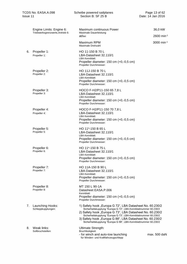
Engine Limits: Engine 6: Triebwerksgrenzwerte,Antrieb 6:
Maximum continuous Power 36,0 kW Maximale Dauerleistung
at/bei 2600 min-1
Maximum RPM 3000 min-1
Maximale Drehzahl
6. Propeller 1: Propeller 1:
HO 11-150 B 70 L LBA-Datasheet 32.110/1 LBA Kennblatt:
Propeller diameter: 150 cm (+0,-0,5 cm) Propeller Durchmesser:
Propeller 2: Propeller 2:
HO 11J-150 B 70 L LBA-Datasheet 32.110/1 LBA Kennblatt:
Propeller diameter: 150 cm (+0,-0,5 cm) Propeller Durchmesser:
Propeller 3: Propeller 3:
HOCO F-H2/P11-150 65 7,8 L LBA-Datasheet 32.110/1 LBA Kennblatt:
Propeller diameter: 150 cm (+0,-0,5 cm) Propeller Durchmesser:
Propeller 4: Propeller 4:
HOCO F-H2/P11-150 70 7,8 L LBA-Datasheet 32.110/1 LBA Kennblatt:
Propeller diameter: 150 cm (+0,-0,5 cm) Propeller Durchmesser:
Propeller 5: Propeller 5:
HO 11*-150 B 65 L LBA-Datasheet 32.110/1 LBA Kennblatt:
Propeller diameter: 150 cm (+0,-0,5 cm) Propeller Durchmesser:
Propeller 6: Propeller 6:
HO 11*-150 B 75 L LBA-Datasheet 32.110/1 LBA Kennblatt:
Propeller diameter: 150 cm (+0,-0,5 cm) Propeller Durchmesser:
Propeller 7: Propeller 7:
HO 11A-150 B 90 L LBA-Datasheet 32.110/1 LBA Kennblatt:
Propeller diameter: 150 cm (+0,-0,5 cm) Propeller Durchmesser:
Propeller 8: Propeller 8:
MT 150 L 90-1A Datasheet EASA.P.006 Kennblatt:
Propeller diameter: 150 cm (+0,-0,5 cm) Propeller Durchmesser:
7. Launching Hooks: Schleppkupplungen:
1) Safety hook „Europa G 72“, LBA Datasheet No. 60.230/2
Sicherheitskupplung “Europa G 72“, LBA-Kennblattnummer 60.230/2 2) Safety hook „Europa G 73“, LBA Datasheet No. 60.230/2
Sicherheitskupplung “Europa G 73“, LBA-Kennblattnummer 60.230/2
3) Safety hook „Europa G 88“, LBA Datasheet No. 60.230/2
Sicherheitskupplung “Europa G 88“, LBA-Kennblattnummer 60.230/2
8. Weak links: Sollbruchstellen:
Ultimate Strength: Bruchfestigkeit: - for winch and auto-tow launching max. 500 daN für Winden- und Kraftfahrzeugschlepp
TCDS No. EASA.A.098 Scheibe powered sailplanes Section B: SF 25 B
Page 14 of 62 Date: 14 Jan 2016 Issue 11
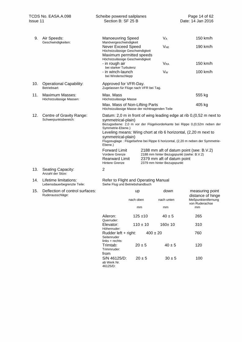
9. Air Speeds: Geschwindigkeiten:
Manoeuvring Speed VA 150 km/h Manövergeschwindigkeit Never Exceed Speed VNE 190 km/h Höchstzulässige Geschwindigkeit
Maximum permitted speeds Höchstzulässige Geschwindigkeit - in rough air VRA 150 km/h bei starker Turbulenz
- in winch-launch VW 100 km/h bei Windenschlepp
10. Operational Capability: Betriebsart:
Approved for VFR-Day. Zugelassen für Flüge nach VFR bei Tag.
11. Maximum Masses: Höchstzulässige Massen:
Max. Mass 555 kg Höchstzulässige Masse
Max. Mass of Non-Lifting Parts 405 kg
Höchstzulässige Masse der nichttragenden Teile
12. Centre of Gravity Range: Schwerpunktsbereich:
Datum: 2,0 m in front of wing leading edge at rib 0,(0,52 m next to symmetrical-plain) Bezugsebene: 2,0 m vor der Flügelvorderkante bei Rippe 0,(0,52m neben der Symmetrie-Ebene.)
Leveling means: Wing chort at rib 6 horizontal, (2,20 m next to symmetrical-plain) Flugzeuglage : Flügelsehne bei Rippe 6 horizontal, (2,20 m neben der Symmetrie- Ebene.)
Forward Limit 2188 mm aft of datum point (see: B.V.2) Vordere Grenze 2188 mm hinter Bezugspunkt (siehe: B.V.2) Rearward Limit 2379 mm aft of datum point Hintere Grenze 2379 mm hinter Bezugspunkt
13. Seating Capacity: Anzahl der Sitze:
2
14. Lifetime limitations: Lebensdauerbegrenzte Teile:
Refer to Flight and Operating Manual Siehe Flug und Betriebshandbuch
15. Deflection of control surfaces: Ruderausschläge:
up down measuring point distance of hinge nach oben nach unten Meßpunktentfernung von Ruderachse mm mm mm
Aileron: 125 ±10 40 ± 5 265 Querruder:
Elevator: 110 ± 10 160± 10 310 Höhenruder:
Rudder left + right: 400 ± 20 760 Seitenruder links + rechts:
Trimtab: 20 ± 5 40 ± 5 120 Trimmruder:
from S/N 46125/D: 20 ± 5 30 ± 5 100 ab Werk Nr. 46125/D:
TCDS No. EASA.A.098 Scheibe powered sailplanes Section B: SF 25 B
Page 15 of 62 Date: 14 Jan 2016 Issue 11
B.IV. Operating and Service Instructions Betriebs- und Instandhaltungsanweisungen
1. Flight and Operating Handbook SF 25 „Falke“; series B, issue February 1972, with admission note. Flug und Betriebs Handbuch SF 25 „Falke“, Baureihe B, Ausgabe Februar 1972 mit Anerkennungsvermerk.
2. (Flight and Operating Manual for powered sailplane SF 25 “Falke“,series B, issue April 1977, LBA-approved.) *) (see: B.V.3) Flug-und Betriebshandbuch für den Motorsegler SF 25 „Falke“, Baureihe B, Ausgabe April 1977, LBA-anerkannt (siehe: B.V.3)
3. (Flight and Operating Manual for powered sailplane SF 25 “Falke“,variant C, issue March 1972, LBA-approved.) *) See: B.V.4) Flug-und Betriebshandbuch für den Motorsegler SF 25 „Falke“, Baureihe C, Ausgabe März 1972, LBA-anerkannt (siehe: B.V.4)
4. (Flight and Operating Manual for powered sailplane SF 25 B “Falke“,issue November 1992, LBA-approved.) *) (see: B.V.9) Flug-und Betriebshandbuch für den Motorsegler SF 25 B „Falke“, Ausgabe November 1992, Flughandbuch LBA-anerkannt. (siehe: B.V.9)
5. (Operating Manual SF 25 „Falke“, variant B.) *) Betriebshandbuch SF 25 „Falke“, Baureihe B.
6. (Operating Manual for the flight engine Stark Stamo MS 1500 for variants Stark Stamo MS 1500/1 and Stark Stamo MS 1500/2, according to the engine datasheet Nr. 4570.) *) Betriebsanweisungen für den Flugmotor Stark Stamo MS 1500 mit den Baureihen Stark Stamo MS 1500/1 und Stark Stamo MS 1500/2 gemäß den Angaben im Motor-Kennblatt Nr. 4570.
7. (Operating Instructions fort he flight engine Stark 45 SG, according to the engine datasheet Nr. 4581.) *) Betriebsanweisungen für den Flugmotor Stark 45 SG gemäß den Angaben im Motor- Kennblatt Nr. 4581.
8. (Operating Manual flight engine for powered sailplane;Sportavia-Limbach SL 1700 E, Limbach SL 1700 EA and other variants, LAB-approved.) *) (see: B.V.3) Betriebshandbuch Flugmotoren für Motorsegler; Sportavia-Limbach SL 1700 E, Limbach SL 1700 EA und weitere Baureihen, LBA-anerkannt. (siehe: B.V.3)
9. (Operating Manual flight engine for powered sailplane; Sauer SE 1800-1-ES 1 from production date 01 March 1998 on.) *) Betriebshandbuch Flugmotor für Motorsegler; Sauer SE 1800-1-ES1 ab Herstellungsdatum 01.03.1998.
10. Maintenance and Operating Instruction E 112 for the MT propeller. Wartungs-und Betriebsanweisung E 112 für MT-Propeller.
11. Operating Instruction and Maintenance Manual Nr. 0207.71, LBA-approved, for fixed wooden- Composite-Propellers of company Hoffmann GmbH&Co KG. Betriebs-und Wartungshandbuch Nr. 0207.71, LBA-anerkannt, für feste Holz-Composite-Propeller der Firma Hoffmann GbmH& Co. KG.
12. Operating Instructions for the Tost release, latest approved version. Betriebshandbuch für die TOST Schleppkupplung , in der jeweils gültigen Ausgabe.
*) Operating and Service Instructions in brackets are existing only in German language. Operating and
Service Instructions in other languages, approved by other European NAA’s, are accepted. Betriebs und Instandhaltungsanweisungen in Klammern existieren nur in deutscher Sprache.Betriebs und Instandhaltungs- anweisungen in anderen Sprachen,genehmigt durch andere europäische NAA’s, sind anerkannt.

TCDS No. EASA.A.098 Scheibe powered sailplanes Section B: SF 25 B
Page 16 of 62 Date: 14 Jan 2016 Issue 11
B.V. Notes Bemerkungen
1. Partly manufacturing is allowed during amateur production. Teilherstellung im Amateurbau ist zulässig.
2. A maximum forward limit of flight centre of gravity of 2,152 m aft of datum point, according Technical Note Nr.653-30 of company Scheibe Flugzeugbau GmbH, dated 05 April 1977, LBA approved is allowed. Eine größte Vorlage des Fluggewichts-Schwerpunktes von 2,152 m hinter Bezugsebene gemäß den Angaben der TM 653-30 der Firma Scheibe Flugzeugbau GmbH vom 05.04.1977, LBA-anerkannt, ist zulässig.
3. The Installation of the engine Limbach SL 1700 EA in combination with the propeller HO 11*-150 B 65 L or HO 11*-150 B 75 L , increase of maximum mass to 565 Kg and max. mass of non-lifting parts of 415 kg and a forward limit of flight centre of gravity with 2,152 m aft of datum point, according to Technical Note Nr.653-31, (issue 2) of company Scheibe Flugzeugbau GmbH, in combination with Modification Nr. 152, Firma Scheibe Flugzeugbau GmbH, dated 17 October 1979, LBA approved is allowed.
Der Einbau des Motors Limbach SL 1700 EA in Verbindung mit der Luftschraube HO 11*-150 B 65 L oder HO 11*-150 B 75 L, die Erhöhung der Höchstmasse auf 565 Kg und die Höchstmasse der nichttragenden teile auf 415 Kg soiwie eine größte Vorlage des Fluggewichts-Schwerpunktes von 2,152 m hinter Bezugsebene gemäß den Angaben der TM Nr. 653-31 (Ausgabe 2) (in Verbindung mit der Änderung Nr. 152) der Firma Scheibe Flugzeugbau GmbH vom 17.10.1979, LBA-anerkannt, ist zulässig.
4. Modification of the serial No. 46201, 46203, 46204, 46206, 46209, 46210 and from serial No.46212 up to serial No. 46258 inclusive into variant SF 25 C “Falke” according to Technical Note 653-32, of company Scheibe Flugzeugbau GmbH dated 20.Juno 1977, LBA-approved, is allowed. These motorgliders are marked additional to the serial No. with a additional “C”. Der Umbau der Werk.Nr. 46201, 46203, 46204, 46206, 46209, 46210 und von Werk.Nr. 46212 bis einschließlich Werk.Nr. 46258 in die Baureihe SF 25 C “Falke” gemäß den Angaben der TM Nr. 653-32 der Firma Scheibe Flugzeugbau GmbH vom
20.06.1977, LBA-anerkannt, ist zulässig. Die umgebauten Motorsegler erhalten zu ihrer alten Werknummer den Zusatz “C”.
5. Modification of the SF 25 “Falke” variant “B” into the variant “D” according to Technical Note No. 653-33 (issue 2), Firma Scheibe Flugzeugbau GmbH dated 17October 1979, LBA-approved, is allowed. These motorglider are marked additional to the serial No.with a additional “D”.
Der Umbau von Motorseglern SF 25 “Falke” der Baureihe B in die Baureihe D gemäß den Angaben der TM Nr. 653-33
(Ausgabe 2) der Firma Scheibe Flugzeugbau GmbH vom 17.10.1979, LBA-anerkannt, ist zulässig. Die umgebauten
Motorsegler erhalten zu ihrer alten Werknummer den Zusatz “D”.
6. The propeller name HO 11*-… is identical with the propeller name HO 11A-…
Die Propeller-Bezeichnung HO 11*-… ist gleichbedeutend mit der Propeller-Bezeichnung HO 11A-…
7. The installation of an electrical starter according to modification Nr. 2, of company Pieper,Stark&Co., Motorenbau, dated 01 January 1972, LBA-approved, in combination with the modification No.108, of company Scheibe Flugzeugbau GmbH dated 14 March 1972, LBA-approved, is allowed.
Der Einbau einer elektrischen Starteranlage gemäß den Angaben der Änderung Nr. 2 der Firma Pieper, Stark&Co. Motorenbau vom 01.01.1972, LBA-anerkannt , in Verbindung mit der Änderung Nr. 108 der Firma Scheibe Flugzeugbau GmbH, vom 14.03.1972 , LBA-anerkannt, ist zulässig.
8. The installation of an exhaust system with heater according to Technical Note Nr. 653-8/75 dated 17 November 1975, LBA-approved, is allowed. Der Einbau einer Abgasanlage mit Heizung gemäß den Angaben der TM Nr. 653-8/75 vom 17.11.1975, LBA-anerkannt, ist zulässig.
9. The installation of the engine Sauer SE 1800 E1S in combination with the propeller MT 150 L 90- 1A or HO 11A- 150 B 90 L according to Technical Note No. 653-59, of company Scheibe Flugzeugbau GmbH, dated 19 January 1993, LBA approved is allowed. The TM No. 653-59 is also allowed for the engines 5 and 6, if the production date is later than the 01 March 1998. Der Einbau des Motors Sauer SE 1800 E1S in Verbindung mit dem Propeller MT 150 L90-1A bzw. HO 11A- 150 B 90 L
entsprechend der TM Nr. 653-59 der Firma Scheibe Flugzeugbau GmbH vom 19.01.1993, LBA-anerkannt, ist zulässig.
Die TM Nr. 653-59 gilt auch für die Motoren 5 und 6, wenn deren Herstellungsdatum nach dem 01.03.1998 liegt.
10. Additional to the equipment (B.III, point 3), a cylinder head temperature indicator is needed to be installed if cowl flaps are build in.
Zusätzlich zu der Ausrüstung nach (B.III, Punkt 3) ist ein Zylinderkopfthermometer einzubauen, wenn eine Kühlklappe eingebaut ist.
TCDS No. EASA.A.098 Scheibe powered sailplanes Section B: SF 25 B
Page 17 of 62 Date: 14 Jan 2016 Issue 11
11. With the engines Stamo MS 1500/1 and 1500/2, equipped with the LBA-approved modification No.5, of company Stamo, shouldered nut or with a propeller hub plug, the use of propeller HO 11J- 150 B 70 L. (with the propeller hub plug holes) has to be used.
Mit den Motoren Stamo 1500/1 und 1500/2, die gemäß der LBA-anerkannten Änderung Nr. 5 der Firma Stamo mit Bundmuttern bzw. Propellerflansch-Zapfen ausgerüstet sind., ist der Propeller HO 11J- 150 B 70 L zu verwenden, der die entsprechenden Zapfenlöcher hat.
12. Basic aerobatic see Flight Manual.
Geeignet für einfachen Kunstflug gem. den Angaben im Flughandbuch
TCDS No. EASA.A.098 Scheibe powered sailplanes Section C: SF 25 C
Page 18 of 62 Date: 14 Jan 2016 Issue 11
Section C: SF 25 C
C.I. General Allgemeines
1. Data Sheet No.: Kennblatt-Nr.:
EASA.A.098
2. a) Type: (Muster) b) Variant: (Baureihe)
c) Salesname: (Verkaufsbezeichnung)
SF 25 SF 25 C “Falke”
3. Airworthiness Category: Lufttüchtigkeitskategorie:
Powered Sailplane, LBA-note Nr. 10.05, Utility Motorsegler, LBA-Mitteilung Nr. 10.05 Utility
4. Manufacturer: Hersteller:
Scheibe-Flugzeugbau GmbH August Pfaltz-Straße 23 85221 Dachau Sportavia-Pützer GmbH& Co. KG Flugplatz Dahlemer Binz 5377 Dahlem-Schmidtheim SCHEIBE-AIRCRAFT-GMBH Sudetenstraße 57/2, Flugplatz Heubach D-73540 Heubach
5. LBA Type Certification Date: Datum der LBA-Musterzulassung:
15 September 1972
6. This TCDS replaces LBA TCDS No. 653, Issue 38 Dieses Kennblatt ersetzt das LBA Kennblatt Nr. 653, Ausgabe 38
C.II. Certification Basis Zulassungsbasis
1. Certification Basis: Zulassungsbasis:
Defined by LBA Confirmation letter with certification standards, dated 15 February 1971. Bestätigungsschreiben mit Zulassungsbedingungen.
2. Airworthiness Requirements: Lufttüchtigkeitsforderungen:
LBA-note Nr. 10.05, “Temporary Guidelines for the Exami- nation and Certification of Powered Sailplanes”, Issue 08 January 1959, with changes dated 14 April 1967. LBA-Mitteilung Nr. 10.05 “Vorläufige Richtlinien für die Prüfung und Zulassung von Motorseglern”, Ausgabe 08 Januar 1959, mit Änderungen vom 14.04.1967 zu dieser Mitteilung.
Joint Airworthiness Requirements for Sailplanes and Powered Sailplanes (JAR 22), Change 4, January 1988. Lufttüchtigkeitsforderungen für Segelflugzeuge und Motorsegler JAR-22, (Change 4 der englischen Originalausgabe vom Januar 1988.
3. Requirements elected to comply: Gewählte Forderungen:
LBA-Note Nr. 10.05.1 “Summary of Requirements concer- ning Operating Conditions for Powered Sailplanes,issue 23 February 1971. LBA-Mitteilung Nr. 10.05.1 “Zusammenstellung der Forderungen bezüglich des Betriebsverhaltens von Motorseglern”, Ausgabe 23.02.1971.
LBA-Note II 11-603.4/5/86 dated 09 Mai 1986 “Variable pitch-propellers (electrical) continuously variable from take- off to feathering position”. LBA-Vermerk II 11-603.4/5/86 vom 09.05.1986 “Verstellpropeller mit (elektrisch) stufenlosen Verstellmöglichkeiten von Start-bis Segelstellung”.
TCDS No. EASA.A.098 Scheibe powered sailplanes Section C: SF 25 C
Page 19 of 62 Date: 14 Jan 2016 Issue 11
Supplemental Requirements to JAR-22 for the towing of sailplanes by powered sailplanes dated 28 November 1997 (NfL II-5/98). Zusatzforderungen zu JAR-22 für das Schleppen von Segelflugzeugen durch Motorsegler vom 28.11.1997 (NfL II-5/98).
4. Special Conditions: Sonderforderungen:
None Keine
5. Exemptions: Ausnahmen:
None Keine
6. Equivalent Safety Findings: Nachweise gleichwertiger Sicherheit:
None Keine
7. Environmental Standards: Lärmschutzforderungen:
ICAO Annex 16, Volume I (for more details see EASA TCDSN A.098) ICAO Annex 16, Volume I (weitere Informationen in EASA TCDSN A.098)
C.III. Technical Characteristics and Operational Limitations Technische Merkmale und Betriebsgrenzen
1. Type Design Definition: Musterdefinition:
Drawing list SF 25 C dated 13 March 1972, amended by LBA-approved Modifications and Technical Notes. Zeichnungsliste SF 25 C vom 13.03.1972 ergänzt durch LBA-anerkannte Änderungen und Technische Mitteilungen.
2. Description: Beschreibung:
Two-seat, low wing powered sailplane in metal-wood construction, fixed central mainwheel, spoilers on upper wing surface Zweisitziger Tiefdecker Motorsegler in Gemischt-Bauweise, festes zentrales Hauptrad, Störklappen auf der Flügeloberseite.
3. Equipment: Ausrüstung:
Min. Equipment: Mindestausrüstung
1 Air speed indicator Geschwindigkeitsmesser
1 Altimeter Höhenmesser
1 Compass
Magnetkompass
1 RPM indicator Drehzahlmesser
1 Fuel quantity indicator Kraftsoffvorratsanzeiger
1 Elapsed time indicator Betriebsstundenzähler
1 Oilpressure indicator Öldruckanzeige
1 Oil temperature indicator Öltemperaturanzeige
2 4-Point harness (symmetrical) 4-teilige Anschnallgurte (symmetrisch)
2 Parachute or back cushion Fallschirm oder Rückenkissen
TCDS No. EASA.A.098 Scheibe powered sailplanes Section C: SF 25 C
Page 20 of 62 Date: 14 Jan 2016 Issue 11
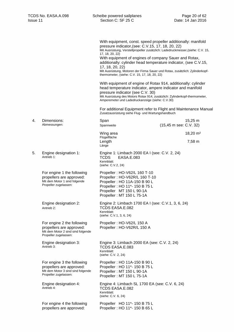
With equipment, const. speed propeller additionally: manifold pressure indicator,(see: C.V.15, 17, 18, 20, 22) Mit Ausrüstung, Verstellpropeller zusätzlich: Ladedruckmesser,(siehe: C.V. 15, 17, 18, 20, 22)
With equipment of engines of company Sauer and Rotax, additionally: cylinder head temperature indicator, (see C.V.15, 17, 18, 20, 22) Mit Ausrüstung, Motoren der Firma Sauer und Rotax, zusätzlich: Zylinderkopf- thermometer, (siehe: C.V. 15, 17, 18, 20, 22)
With equipment of engine of Rotax 914, additionally: cylinder head temperature indicator, ampere indicator and manifold pressure indicator (see C.V. 30) Mit Ausrüstung des Motors Rotax 914, zusätzlich: Zylinderkopf-thermometer, Amperemeter und Ladedruckanzeige (siehe: C.V.30)
For additional Equipment refer to Flight and Maintenance Manual Zusatzausrüstung siehe Flug- und Wartungshandbuch
4. Dimensions: Abmessungen:
Span 15,25 m Spannweite (15,45 m see: C.V. 32)
Wing area 18,20 m² Flügelfläche
Length 7,58 m Länge
5. Engine designation 1: Antrieb 1:
Engine 1: Limbach 2000 EA I (see: C.V. 2, 24) TCDS EASA.E.083 Kennblatt: (siehe: C.V.2, 24)
For engine 1 the following propellers are approved: Mit dem Motor 1 sind folgende Propeller zugelassen:
Propeller : HO-V62/L 160 T-10 Propeller : HO-V62R/L 160 T-10 Propeller : HO 11A-150 B 90 L Propeller : HO 11*- 150 B 75 L Propeller MT 150 L 90-1A Propeller : MT 150 L 75-1A
Engine designation 2: Antrieb 2:
Engine 2: Limbach 1700 EA I (see: C.V.1, 3, 6, 24) TCDS EASA.E.082 Kennblatt: (siehe: C.V.1, 3, 6, 24)
For engine 2 the following propellers are approved: Mit dem Motor 2 sind sind folgende Propeller zugelassen:
Propeller : HO-V62/L 150 A Propeller : HO-V62R/L 150 A
Engine designation 3: Antrieb 3:
Engine 3: Limbach 2000 EA (see: C.V. 2, 24) TCDS EASA.E.083 Kennblatt: (siehe: C.V. 2, 24)
For engine 3 the following propellers are approved: Mit dem Motor 3 sind sind folgende Propeller zugelassen:
Propeller : HO 11A-150 B 90 L Propeller : HO 11*- 150 B 75 L Propeller : MT 150 L 90-1A Propeller : MT 150 L 75-1A
Engine designation 4: Antrieb 4:
Engine 4: Limbach SL 1700 EA (see: C.V. 6, 24) TCDS EASA.E.082 Kennblatt: (siehe: C.V. 6, 24)
For engine 4 the following propellers are approved:
Propeller HO 11*- 150 B 75 L Propeller : HO 11*- 150 B 65 L
TCDS No. EASA.A.098 Scheibe powered sailplanes Section C: SF 25 C
Page 21 of 62 Date: 14 Jan 2016 Issue 11
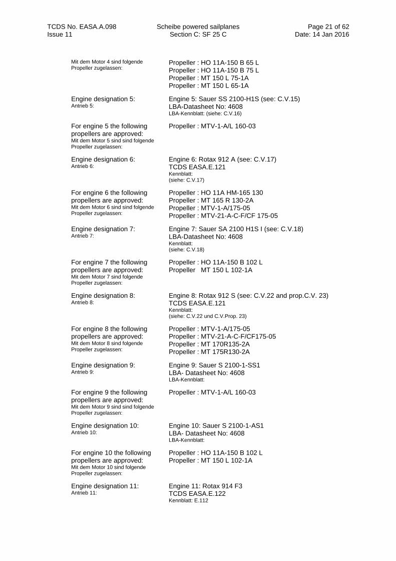
Mit dem Motor 4 sind folgende Propeller zugelassen:
Propeller : HO 11A-150 B 65 L Propeller : HO 11A-150 B 75 L Propeller : MT 150 L 75-1A Propeller : MT 150 L 65-1A
Engine designation 5: Antrieb 5:
Engine 5: Sauer SS 2100-H1S (see: C.V.15) LBA-Datasheet No: 4608 LBA-Kennblatt: (siehe: C.V.16)
For engine 5 the following propellers are approved: Mit dem Motor 5 sind sind folgende Propeller zugelassen:
Propeller : MTV-1-A/L 160-03
Engine designation 6: Antrieb 6:
Engine 6: Rotax 912 A (see: C.V.17) TCDS EASA.E.121 Kennblatt: (siehe: C.V.17)
For engine 6 the following propellers are approved: Mit dem Motor 6 sind sind folgende Propeller zugelassen:
Propeller : HO 11A HM-165 130 Propeller : MT 165 R 130-2A Propeller : MTV-1-A/175-05 Propeller : MTV-21-A-C-F/CF 175-05
Engine designation 7: Antrieb 7:
Engine 7: Sauer SA 2100 H1S I (see: C.V.18) LBA-Datasheet No: 4608 Kennblatt: (siehe: C.V.18)
For engine 7 the following propellers are approved: Mit dem Motor 7 sind folgende Propeller zugelassen:
Propeller : HO 11A-150 B 102 L Propeller MT 150 L 102-1A
Engine designation 8: Antrieb 8:
Engine 8: Rotax 912 S (see: C.V.22 and prop.C.V. 23) TCDS EASA.E.121 Kennblatt: (siehe: C.V.22 und C.V.Prop. 23)
For engine 8 the following propellers are approved: Mit dem Motor 8 sind folgende Propeller zugelassen:
Propeller : MTV-1-A/175-05 Propeller : MTV-21-A-C-F/CF175-05 Propeller : MT 170R135-2A Propeller : MT 175R130-2A
Engine designation 9: Antrieb 9:
Engine 9: Sauer S 2100-1-SS1 LBA- Datasheet No: 4608 LBA-Kennblatt:
For engine 9 the following propellers are approved: Mit dem Motor 9 sind sind folgende Propeller zugelassen:
Propeller : MTV-1-A/L 160-03
Engine designation 10: Antrieb 10:
Engine 10: Sauer S 2100-1-AS1 LBA- Datasheet No: 4608 LBA-Kennblatt:
For engine 10 the following propellers are approved: Mit dem Motor 10 sind folgende Propeller zugelassen:
Propeller : HO 11A-150 B 102 L Propeller : MT 150 L 102-1A
Engine designation 11: Antrieb 11:
Engine 11: Rotax 914 F3 TCDS EASA.E.122 Kennblatt: E.112
TCDS No. EASA.A.098 Scheibe powered sailplanes Section C: SF 25 C
Page 22 of 62 Date: 14 Jan 2016 Issue 11
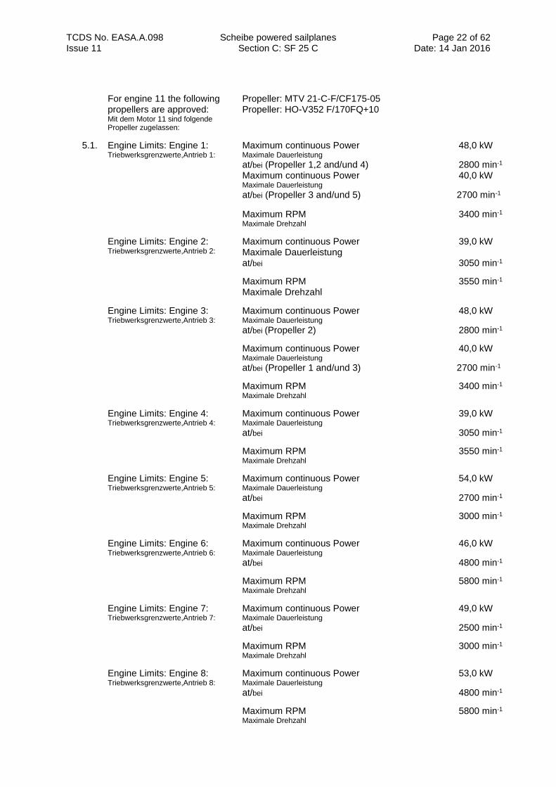
For engine 11 the following propellers are approved: Mit dem Motor 11 sind folgende Propeller zugelassen:
Propeller: MTV 21-C-F/CF175-05 Propeller: HO-V352 F/170FQ+10
5.1. Engine Limits: Engine 1: Triebwerksgrenzwerte,Antrieb 1:
Maximum continuous Power 48,0 kW Maximale Dauerleistung
at/bei (Propeller 1,2 and/und 4) 2800 min-1
Maximum continuous Power 40,0 kW
Maximale Dauerleistung at/bei (Propeller 3 and/und 5) 2700 min-1
Maximum RPM 3400 min-1
Maximale Drehzahl
Engine Limits: Engine 2: Triebwerksgrenzwerte,Antrieb 2:
Maximum continuous Power 39,0 kW Maximale Dauerleistung at/bei 3050 min-1
Maximum RPM 3550 min-1 Maximale Drehzahl
Engine Limits: Engine 3: Triebwerksgrenzwerte,Antrieb 3:
Maximum continuous Power 48,0 kW Maximale Dauerleistung
at/bei (Propeller 2) 2800 min-1
Maximum continuous Power 40,0 kW
Maximale Dauerleistung at/bei (Propeller 1 and/und 3) 2700 min-1
Maximum RPM 3400 min-1
Maximale Drehzahl
Engine Limits: Engine 4: Triebwerksgrenzwerte,Antrieb 4:
Maximum continuous Power 39,0 kW Maximale Dauerleistung
at/bei 3050 min-1
Maximum RPM 3550 min-1
Maximale Drehzahl
Engine Limits: Engine 5: Triebwerksgrenzwerte,Antrieb 5:
Maximum continuous Power 54,0 kW Maximale Dauerleistung
at/bei 2700 min-1
Maximum RPM 3000 min-1
Maximale Drehzahl
Engine Limits: Engine 6: Triebwerksgrenzwerte,Antrieb 6:
Maximum continuous Power 46,0 kW Maximale Dauerleistung
at/bei 4800 min-1
Maximum RPM 5800 min-1
Maximale Drehzahl
Engine Limits: Engine 7: Triebwerksgrenzwerte,Antrieb 7:
Maximum continuous Power 49,0 kW Maximale Dauerleistung
at/bei 2500 min-1
Maximum RPM 3000 min-1
Maximale Drehzahl
Engine Limits: Engine 8: Triebwerksgrenzwerte,Antrieb 8:
Maximum continuous Power 53,0 kW Maximale Dauerleistung
at/bei 4800 min-1
Maximum RPM 5800 min-1
Maximale Drehzahl
TCDS No. EASA.A.098 Scheibe powered sailplanes Section C: SF 25 C
Page 23 of 62 Date: 14 Jan 2016 Issue 11
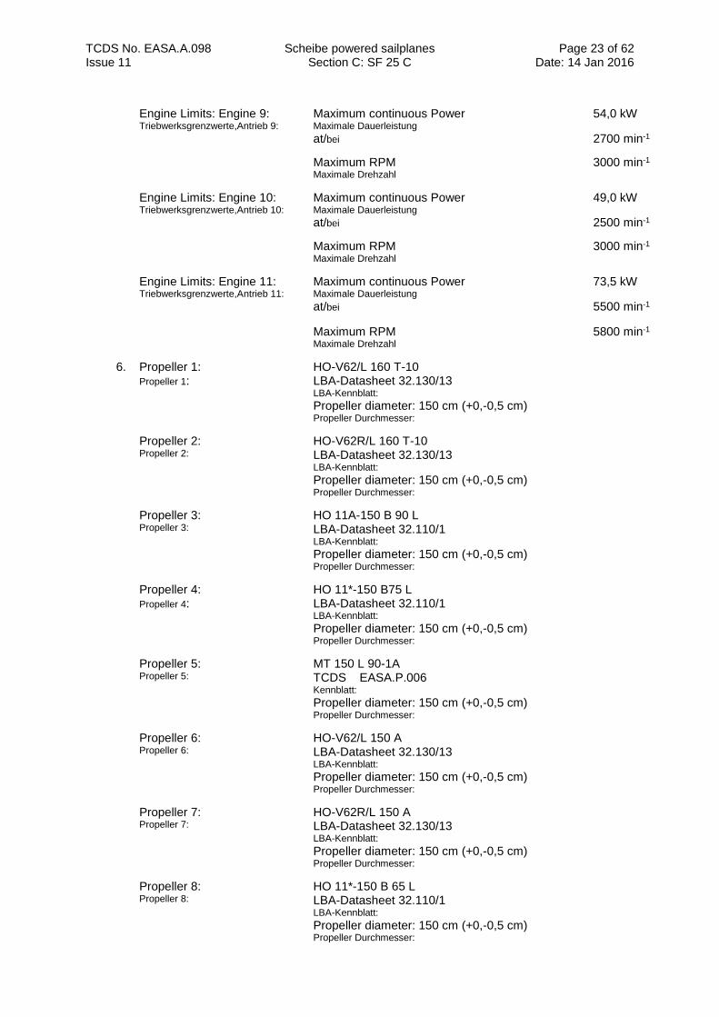
Engine Limits: Engine 9: Triebwerksgrenzwerte,Antrieb 9:
Maximum continuous Power 54,0 kW Maximale Dauerleistung
at/bei 2700 min-1
Maximum RPM 3000 min-1
Maximale Drehzahl
Engine Limits: Engine 10: Triebwerksgrenzwerte,Antrieb 10:
Maximum continuous Power 49,0 kW Maximale Dauerleistung
at/bei 2500 min-1
Maximum RPM 3000 min-1
Maximale Drehzahl
Engine Limits: Engine 11: Triebwerksgrenzwerte,Antrieb 11:
Maximum continuous Power 73,5 kW Maximale Dauerleistung
at/bei 5500 min-1
Maximum RPM 5800 min-1
Maximale Drehzahl
6. Propeller 1: Propeller 1:
HO-V62/L 160 T-10 LBA-Datasheet 32.130/13 LBA-Kennblatt: Propeller diameter: 150 cm (+0,-0,5 cm) Propeller Durchmesser:
Propeller 2: Propeller 2:
HO-V62R/L 160 T-10 LBA-Datasheet 32.130/13 LBA-Kennblatt: Propeller diameter: 150 cm (+0,-0,5 cm) Propeller Durchmesser:
Propeller 3: Propeller 3:
HO 11A-150 B 90 L LBA-Datasheet 32.110/1 LBA-Kennblatt: Propeller diameter: 150 cm (+0,-0,5 cm) Propeller Durchmesser:
Propeller 4: Propeller 4:
HO 11*-150 B75 L LBA-Datasheet 32.110/1 LBA-Kennblatt: Propeller diameter: 150 cm (+0,-0,5 cm) Propeller Durchmesser:
Propeller 5: Propeller 5:
MT 150 L 90-1A TCDS EASA.P.006 Kennblatt: Propeller diameter: 150 cm (+0,-0,5 cm) Propeller Durchmesser:
Propeller 6: Propeller 6:
HO-V62/L 150 A LBA-Datasheet 32.130/13 LBA-Kennblatt: Propeller diameter: 150 cm (+0,-0,5 cm) Propeller Durchmesser:
Propeller 7: Propeller 7:
HO-V62R/L 150 A LBA-Datasheet 32.130/13 LBA-Kennblatt: Propeller diameter: 150 cm (+0,-0,5 cm) Propeller Durchmesser:
Propeller 8: Propeller 8:
HO 11*-150 B 65 L LBA-Datasheet 32.110/1 LBA-Kennblatt: Propeller diameter: 150 cm (+0,-0,5 cm) Propeller Durchmesser:
TCDS No. EASA.A.098 Scheibe powered sailplanes Section C: SF 25 C
Page 24 of 62 Date: 14 Jan 2016 Issue 11
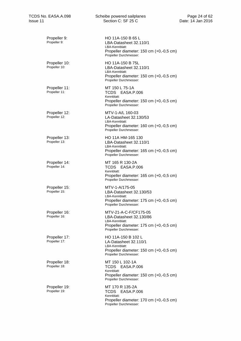
Propeller 9: Propeller 9:
HO 11A-150 B 65 L LBA-Datasheet 32.110/1 LBA-Kennblatt: Propeller diameter: 150 cm (+0,-0,5 cm) Propeller Durchmesser:
Propeller 10: Propeller 10:
HO 11A-150 B 75L LBA-Datasheet 32.110/1 LBA-Kennblatt: Propeller diameter: 150 cm (+0,-0,5 cm) Propeller Durchmesser:
Propeller 11: Propeller 11:
MT 150 L 75-1A TCDS EASA.P.006 Kennblatt: Propeller diameter: 150 cm (+0,-0,5 cm) Propeller Durchmesser:
Propeller 12: Propeller 12:
MTV-1-A/L 160-03 LA-Datasheet 32.130/53 LBA-Kennblatt: Propeller diameter: 160 cm (+0,-0,5 cm) Propeller Durchmesser:
Propeller 13: Propeller 13:
HO 11A HM-165 130 LBA-Datasheet 32.110/1 LBA-Kennblatt: Propeller diameter: 165 cm (+0,-0,5 cm) Propeller Durchmesser:
Propeller 14: Propeller 14:
MT 165 R 130-2A TCDS EASA.P.006 Kennblatt: Propeller diameter: 165 cm (+0,-0,5 cm) Propeller Durchmesser:
Propeller 15: Propeller 15:
MTV-1-A/175-05 LBA-Datasheet 32.130/53 LBA-Kennblatt: Propeller diameter: 175 cm (+0,-0,5 cm) Propeller Durchmesser:
Propeller 16: Propeller 16:
MTV-21-A-C-F/CF175-05 LBA-Datasheet 32.130/86 LBA-Kennblatt: Propeller diameter: 175 cm (+0,-0,5 cm) Propeller Durchmesser:
Propeller 17: Propeller 17:
HO 11A-150 B 102 L LA-Datasheet 32.110/1 LBA-Kennblatt: Propeller diameter: 150 cm (+0,-0,5 cm) Propeller Durchmesser:
Propeller 18: Propeller 18:
MT 150 L 102-1A TCDS EASA.P.006 Kennblatt: Propeller diameter: 150 cm (+0,-0,5 cm) Propeller Durchmesser:
Propeller 19: Propeller 19:
MT 170 R 135-2A TCDS EASA.P.006 Kennblatt: Propeller diameter: 170 cm (+0,-0,5 cm) Propeller Durchmesser:
TCDS No. EASA.A.098 Scheibe powered sailplanes Section C: SF 25 C
Page 25 of 62 Date: 14 Jan 2016 Issue 11
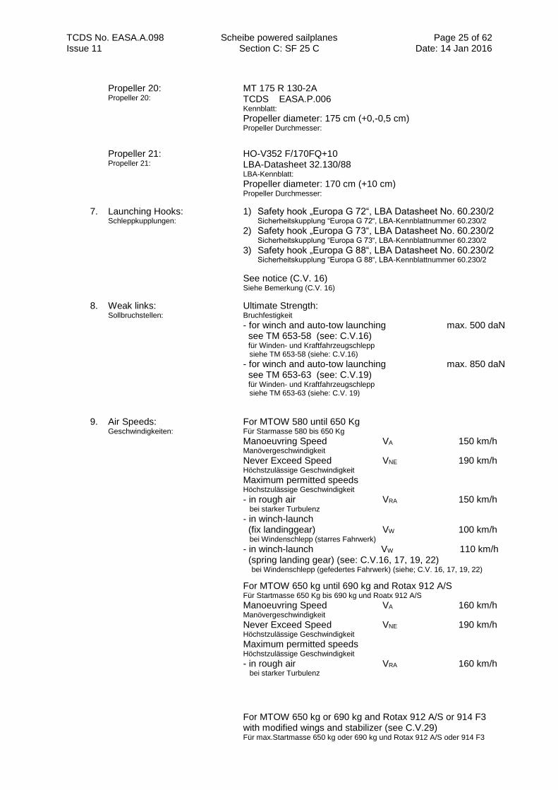
Propeller 20: Propeller 20:
MT 175 R 130-2A TCDS EASA.P.006 Kennblatt: Propeller diameter: 175 cm (+0,-0,5 cm) Propeller Durchmesser:
Propeller 21: Propeller 21:
HO-V352 F/170FQ+10 LBA-Datasheet 32.130/88 LBA-Kennblatt:
Propeller diameter: 170 cm (+10 cm) Propeller Durchmesser:
7. Launching Hooks: Schleppkupplungen:
1) Safety hook „Europa G 72“, LBA Datasheet No. 60.230/2 Sicherheitskupplung “Europa G 72“, LBA-Kennblattnummer 60.230/2
2) Safety hook „Europa G 73“, LBA Datasheet No. 60.230/2 Sicherheitskupplung “Europa G 73“, LBA-Kennblattnummer 60.230/2
3) Safety hook „Europa G 88“, LBA Datasheet No. 60.230/2
Sicherheitskupplung “Europa G 88“, LBA-Kennblattnummer 60.230/2
See notice (C.V. 16) Siehe Bemerkung (C.V. 16)
8. Weak links: Sollbruchstellen:
Ultimate Strength: Bruchfestigkeit - for winch and auto-tow launching max. 500 daN see TM 653-58 (see: C.V.16) für Winden- und Kraftfahrzeugschlepp siehe TM 653-58 (siehe: C.V.16) - for winch and auto-tow launching max. 850 daN see TM 653-63 (see: C.V.19) für Winden- und Kraftfahrzeugschlepp siehe TM 653-63 (siehe: C.V. 19)
9. Air Speeds: Geschwindigkeiten:
For MTOW 580 until 650 Kg Für Starmasse 580 bis 650 Kg
Manoeuvring Speed VA 150 km/h Manövergeschwindigkeit Never Exceed Speed VNE 190 km/h Höchstzulässige Geschwindigkeit
Maximum permitted speeds Höchstzulässige Geschwindigkeit - in rough air VRA 150 km/h bei starker Turbulenz
- in winch-launch (fix landinggear) VW 100 km/h bei Windenschlepp (starres Fahrwerk)
- in winch-launch VW 110 km/h (spring landing gear) (see: C.V.16, 17, 19, 22) bei Windenschlepp (gefedertes Fahrwerk) (siehe; C.V. 16, 17, 19, 22)
For MTOW 650 kg until 690 kg and Rotax 912 A/S Für Startmasse 650 Kg bis 690 kg und Roatx 912 A/S
Manoeuvring Speed VA 160 km/h Manövergeschwindigkeit Never Exceed Speed VNE 190 km/h Höchstzulässige Geschwindigkeit
Maximum permitted speeds Höchstzulässige Geschwindigkeit - in rough air VRA 160 km/h bei starker Turbulenz
For MTOW 650 kg or 690 kg and Rotax 912 A/S or 914 F3 with modified wings and stabilizer (see C.V.29) Für max.Startmasse 650 kg oder 690 kg und Rotax 912 A/S oder 914 F3
TCDS No. EASA.A.098 Scheibe powered sailplanes Section C: SF 25 C
Page 26 of 62 Date: 14 Jan 2016 Issue 11
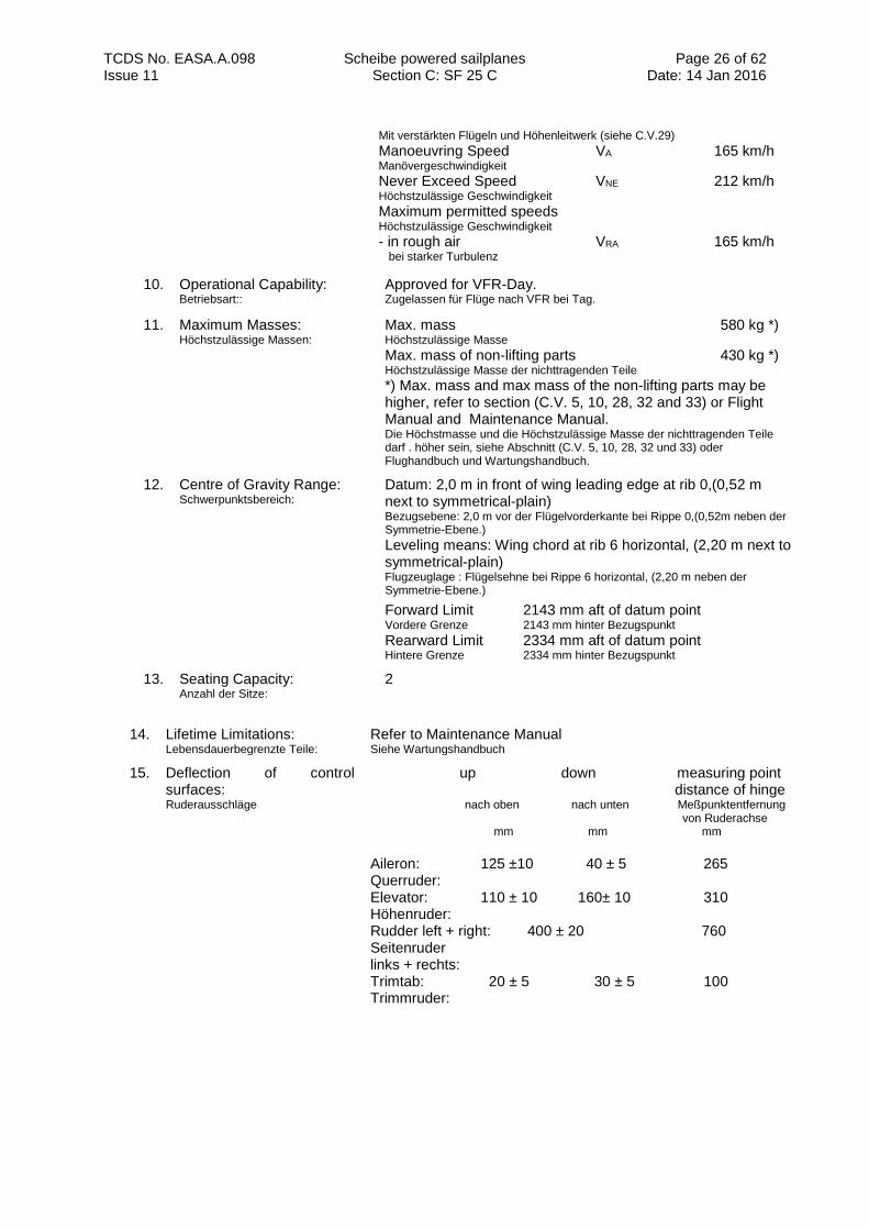
Mit verstärkten Flügeln und Höhenleitwerk (siehe C.V.29) Manoeuvring Speed VA 165 km/h Manövergeschwindigkeit Never Exceed Speed VNE 212 km/h Höchstzulässige Geschwindigkeit
Maximum permitted speeds Höchstzulässige Geschwindigkeit - in rough air VRA 165 km/h bei starker Turbulenz
10. Operational Capability: Betriebsart::
Approved for VFR-Day. Zugelassen für Flüge nach VFR bei Tag.
11. Maximum Masses: Höchstzulässige Massen:
Max. mass 580 kg *) Höchstzulässige Masse
Max. mass of non-lifting parts 430 kg *)
Höchstzulässige Masse der nichttragenden Teile
*) Max. mass and max mass of the non-lifting parts may be higher, refer to section (C.V. 5, 10, 28, 32 and 33) or Flight Manual and Maintenance Manual. Die Höchstmasse und die Höchstzulässige Masse der nichttragenden Teile darf . höher sein, siehe Abschnitt (C.V. 5, 10, 28, 32 und 33) oder Flughandbuch und Wartungshandbuch.
12. Centre of Gravity Range: Schwerpunktsbereich:
Datum: 2,0 m in front of wing leading edge at rib 0,(0,52 m next to symmetrical-plain) Bezugsebene: 2,0 m vor der Flügelvorderkante bei Rippe 0,(0,52m neben der Symmetrie-Ebene.)
Leveling means: Wing chord at rib 6 horizontal, (2,20 m next to symmetrical-plain) Flugzeuglage : Flügelsehne bei Rippe 6 horizontal, (2,20 m neben der Symmetrie-Ebene.)
Forward Limit 2143 mm aft of datum point Vordere Grenze 2143 mm hinter Bezugspunkt Rearward Limit 2334 mm aft of datum point Hintere Grenze 2334 mm hinter Bezugspunkt
13. Seating Capacity: Anzahl der Sitze:
2
14. Lifetime Limitations: Lebensdauerbegrenzte Teile:
Refer to Maintenance Manual Siehe Wartungshandbuch
15. Deflection of control surfaces: Ruderausschläge
up down measuring point distance of hinge nach oben nach unten Meßpunktentfernung von Ruderachse mm mm mm
Aileron: 125 ±10 40 ± 5 265 Querruder: Elevator: 110 ± 10 160± 10 310 Höhenruder: Rudder left + right: 400 ± 20 760 Seitenruder links + rechts: Trimtab: 20 ± 5 30 ± 5 100 Trimmruder:
TCDS No. EASA.A.098 Scheibe powered sailplanes Section C: SF 25 C
Page 27 of 62 Date: 14 Jan 2016 Issue 11
C.IV. Operating and Service Instructions Betriebs- und Instandhaltungsanweisungen
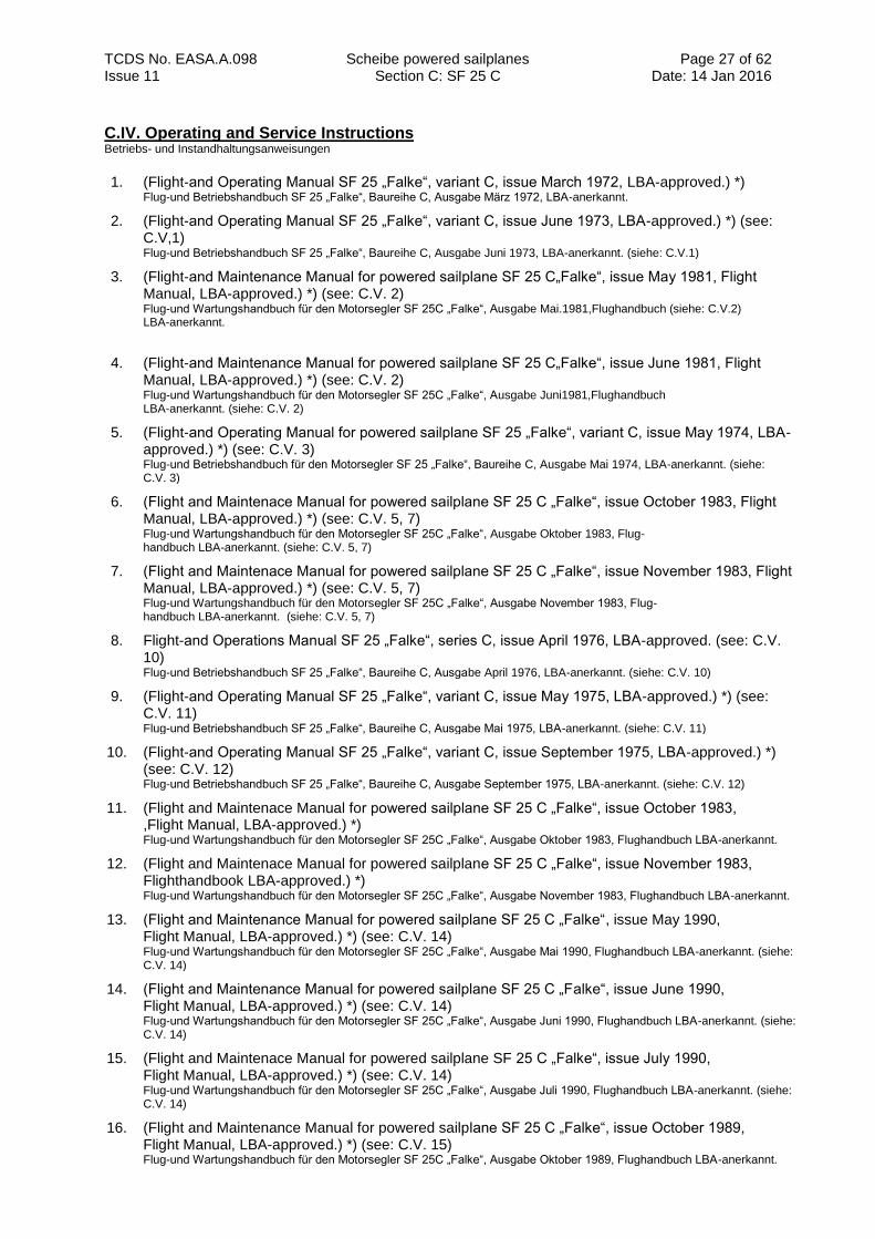
1. (Flight-and Operating Manual SF 25 „Falke“, variant C, issue March 1972, LBA-approved.) *) Flug-und Betriebshandbuch SF 25 „Falke“, Baureihe C, Ausgabe März 1972, LBA-anerkannt.
2. (Flight-and Operating Manual SF 25 „Falke“, variant C, issue June 1973, LBA-approved.) *) (see: C.V,1) Flug-und Betriebshandbuch SF 25 „Falke“, Baureihe C, Ausgabe Juni 1973, LBA-anerkannt. (siehe: C.V.1)
3. (Flight-and Maintenance Manual for powered sailplane SF 25 C„Falke“, issue May 1981, Flight Manual, LBA-approved.) *) (see: C.V. 2) Flug-und Wartungshandbuch für den Motorsegler SF 25C „Falke“, Ausgabe Mai.1981,Flughandbuch (siehe: C.V.2) LBA-anerkannt.
4. (Flight-and Maintenance Manual for powered sailplane SF 25 C„Falke“, issue June 1981, Flight Manual, LBA-approved.) *) (see: C.V. 2) Flug-und Wartungshandbuch für den Motorsegler SF 25C „Falke“, Ausgabe Juni1981,Flughandbuch LBA-anerkannt. (siehe: C.V. 2)
5. (Flight-and Operating Manual for powered sailplane SF 25 „Falke“, variant C, issue May 1974, LBA-approved.) *) (see: C.V. 3) Flug-und Betriebshandbuch für den Motorsegler SF 25 „Falke“, Baureihe C, Ausgabe Mai 1974, LBA-anerkannt. (siehe: C.V. 3)
6. (Flight and Maintenace Manual for powered sailplane SF 25 C „Falke“, issue October 1983, Flight Manual, LBA-approved.) *) (see: C.V. 5, 7) Flug-und Wartungshandbuch für den Motorsegler SF 25C „Falke“, Ausgabe Oktober 1983, Flug- handbuch LBA-anerkannt. (siehe: C.V. 5, 7)
7. (Flight and Maintenace Manual for powered sailplane SF 25 C „Falke“, issue November 1983, Flight Manual, LBA-approved.) *) (see: C.V. 5, 7) Flug-und Wartungshandbuch für den Motorsegler SF 25C „Falke“, Ausgabe November 1983, Flug- handbuch LBA-anerkannt. (siehe: C.V. 5, 7)
8. Flight-and Operations Manual SF 25 „Falke“, series C, issue April 1976, LBA-approved. (see: C.V. 10) Flug-und Betriebshandbuch SF 25 „Falke“, Baureihe C, Ausgabe April 1976, LBA-anerkannt. (siehe: C.V. 10)
9. (Flight-and Operating Manual SF 25 „Falke“, variant C, issue May 1975, LBA-approved.) *) (see: C.V. 11) Flug-und Betriebshandbuch SF 25 „Falke“, Baureihe C, Ausgabe Mai 1975, LBA-anerkannt. (siehe: C.V. 11)
10. (Flight-and Operating Manual SF 25 „Falke“, variant C, issue September 1975, LBA-approved.) *) (see: C.V. 12) Flug-und Betriebshandbuch SF 25 „Falke“, Baureihe C, Ausgabe September 1975, LBA-anerkannt. (siehe: C.V. 12)
11. (Flight and Maintenace Manual for powered sailplane SF 25 C „Falke“, issue October 1983, ,Flight Manual, LBA-approved.) *) Flug-und Wartungshandbuch für den Motorsegler SF 25C „Falke“, Ausgabe Oktober 1983, Flughandbuch LBA-anerkannt.
12. (Flight and Maintenace Manual for powered sailplane SF 25 C „Falke“, issue November 1983, Flighthandbook LBA-approved.) *) Flug-und Wartungshandbuch für den Motorsegler SF 25C „Falke“, Ausgabe November 1983, Flughandbuch LBA-anerkannt.
13. (Flight and Maintenance Manual for powered sailplane SF 25 C „Falke“, issue May 1990, Flight Manual, LBA-approved.) *) (see: C.V. 14) Flug-und Wartungshandbuch für den Motorsegler SF 25C „Falke“, Ausgabe Mai 1990, Flughandbuch LBA-anerkannt. (siehe: C.V. 14)
14. (Flight and Maintenance Manual for powered sailplane SF 25 C „Falke“, issue June 1990, Flight Manual, LBA-approved.) *) (see: C.V. 14) Flug-und Wartungshandbuch für den Motorsegler SF 25C „Falke“, Ausgabe Juni 1990, Flughandbuch LBA-anerkannt. (siehe: C.V. 14)
15. (Flight and Maintenace Manual for powered sailplane SF 25 C „Falke“, issue July 1990, Flight Manual, LBA-approved.) *) (see: C.V. 14) Flug-und Wartungshandbuch für den Motorsegler SF 25C „Falke“, Ausgabe Juli 1990, Flughandbuch LBA-anerkannt. (siehe: C.V. 14)
16. (Flight and Maintenance Manual for powered sailplane SF 25 C „Falke“, issue October 1989, Flight Manual, LBA-approved.) *) (see: C.V. 15) Flug-und Wartungshandbuch für den Motorsegler SF 25C „Falke“, Ausgabe Oktober 1989, Flughandbuch LBA-anerkannt.
TCDS No. EASA.A.098 Scheibe powered sailplanes Section C: SF 25 C
Page 28 of 62 Date: 14 Jan 2016 Issue 11
(siehe: C.V. 15)
17. (Flight and Maintenance Manual for powered sailplane SF 25 C „Falke“, issue March 1997, Flight Manual, LBA-approved.) *) (see: C.V. 17) Flug-und Wartungshandbuch für den Motorsegler SF 25 C „Falke“, Ausgabe März 1997, Flughandbuch LBA-anerkannt. (siehe: C.V. 17)
18. (Flight and Maintenance Manual for powered sailplane SF 25 C „Falke“, issue March 1997, Flight Manual, LBA-approved.) *) (see: C.V. 17) Flug-und Wartungshandbuch für den Motorsegler SF 25 C „Falke“, Ausgabe März 1997, Flughandbuch LBA-anerkannt. (siehe: C.V. 17)
19. (Flight and Maintenance Manual for powered sailplane SF 25 C „Falke“, issue March 1997, Flight Manual, LBA-approved.) *) (see: C.V. 17) Flug-und Wartungshandbuch für den Motorsegler SF 25 C „Falke“, Ausgabe März 1997, Flughandbuch LBA-anerkannt. (siehe: C.V. 17)
20. (Flight and Maintenance Manual for powered sailplane SF 25 C „Falke“, issue August 1992, Flight Manual, LBA-approved.) *) (see: C.V. 18) Flug-und Wartungshandbuch für den Motorsegler SF 25 C „Falke“, Ausgabe August 1992, Flughandbuch LBA-anerkannt. (siehe: C.V. 18)
21. Flight and Maintenance Manual for powered sailplane SF 25 C „Falke“, issue March 1997, Flight Manual, LBA-approved. (see: C.V. 20) Flug-und Wartungshandbuch für den Motorsegler SF 25 C „Falke“, Ausgabe März 1997, Flughandbuch LBA-anerkannt. (siehe: C.V. 20)
22. (Flight and Maintenance Manual for powered sailplane SF 25 C „Falke“, issue July 1997, Flight Manual, LBA-approved.) *) (see: C.V. 18) Flug-und Wartungshandbuch für den Motorsegler SF 25 C „Falke“, Ausgabe Juli 1997, Flughandbuch LBA-anerkannt. (siehe: C.V. 18)
23. (Flight Manual SF 25 C „Falke“, issue March 1997,(FHB) LBA-approved.) *) (see: C.V. 22) Flughandbuch für SF 25 C „Falke“, Ausgabe März 1997, (FHB), LBA-anerkannt. (siehe: C.V. 22)
24. Flightmanual SF 25 C „Falke“, issue March 1997,(FHB) LBA-approved. (see: C.V. 26) Flughandbuch für SF 25 C „Falke“, Ausgabe März 1997, (FHB), LBA-anerkannt. (siehe: C.V. 26)
25. (Operating Manuals SF 25 C „Falke“.) *) Betriebshandbücher SF 25 C „Falke“.
26. (Maintenance Manuals SF 25 C „Falke“.) *) Wartungshandbücher SF 25 C „Falke“.
27. (Maintenance Manual SF 25 C „Falke“, issue March 1997.) *) (see: C.V. 22) Wartungshandbuch SF 25 C „Falke“, Ausgabe März 1997. (siehe: C.V. 22)
28. Maintenance Manual SF 25 C „Falke“, issue March 1997. (see: C.V. 26) Wartungshandbuch SF 25 C „Falke“, Ausgabe März 1997, (siehe: C.V. 26)
29. (Operating Manual fligth engines for powered sailplane Sportavia-Limbach SL 1700 E, Limbach SL 1700 EA and series, LBA-approved.) *) Betriebshandbuch- Flugmotoren für Motorsegler Sportavia-Limbach SL 1700 E, Limbach SL 1700 EA und weitere Baureihen, LBA-anerkannt.
30. (Operating Manual fligth engines for powered sailplane Limbach L 2000 and series, LBA-approved.) *) Betriebshandbuch- Flugmotoren für Motorsegler Limbach L 2000 und weitere Baureihen, LBA-anerkannt.
31. (Operating Manual fligth engines for powered sailplane SS 2100 H1S.) *) Betriebshandbuch Flugmotor für Motorsegler SS 2100 H1S..
32. Operating Manual Sauer Engine S 2100-1-SS1 from production date 01 March 1998 on. Betriebshandbuch Sauer-Motor S 2100-1-SS1 ab Herstellungsdatum 01.03.1998.
33. Operating Manual for Rotax 912 series. Betriebshandbuch für Rotax 912 Serie.
34. Operating Manual flight engine for powered sailplane SA 2100 H1S, Operating Manual Sauer- engine S 2100-1-AS1 up to production date 01 March 1998 on. Betriebshandbuch Flugmotor für Motorsegler SA 2100 H1S, Betriebshandbuch Sauer-Motor S 2100-1-AS1 ab
Herstellungsdatum 01.03.1998.
35. Operating and Maintenance Manual for fixed wooden-composite propeller Nr. 0207.71. Betriebs-und Wartungshandbuch feste Holz-Composite Propeller Nr. 0207.71.
TCDS No. EASA.A.098 Scheibe powered sailplanes Section C: SF 25 C
Page 29 of 62 Date: 14 Jan 2016 Issue 11
36. Operating and Maintenance Manual for the series HO-V62, HO-V62-R. Betriebs-und Wartungshandbuch für die Baureihen HO-V62, HO-V62-R.
37. MT-Propeller Operating and Maintenance Instructions E 112. MT-Propeller: Betriebs-und Wartungsanweisung E-112.
38. MT-Propeller Operating and Installation Instructions Nr. E-118 for the electrical feathering propeller MTV-1-() and MTV-20-(). MT-Propeller: Betriebs-und Einbauanweisung Nr. E-118 für elektrische Verstellpropeller MTV-1-() und MTV-20-().
39. MT-Propeller Operating and Installation Instructions Nr. E-124 for hydraulical feathering propeller MTV-1-() and MTV-20-(), latest approved version. MT-Propeller: Betriebs-und Einbauanweisung Nr. E-124 für hydraulische Verstellpropeller (MTV-21-) in der jeweils gültigen Ausgabe.
40. Flight and Maintenance Manual for powered sailplane SF 25 C „Falke“, issue March 1997,Rev.7, EASA approval No. AC.11014 on 02.April 2009 (see: C.V. 28) Flug-und Wartungshandbuch für den Motorsegler SF 25 C „Falke“, Ausgabe März 1997, Rev. 7, EASA Freigabe Nr. AC.11014 vom 02.April 2009 (siehe: C.V. 28)
41. Flight and Maintenance Manual for powered sailplane SF 25 C „Falke“ with Rotax 914 F engine, issue December 2009, Rev.1, EASA approval No. AC.10030613 on 25.June 2010 Flug-und Wartungshandbuch für den Motorsegler SF 25 C „Falke“ mit Rotax 914 F - Motor, Ausgabe Dezember 2009, Rev.1, EASA Freigabe Nr. AC.10030613 vom 25.June 2010
42. Operating Instructions for the Tost release, latest approved version. (see: C.V.16, 19) Betriebshandbuch für die TOST Schleppkupplung , in der jeweils gültigen Ausgabe. (siehe: C.V. 16, 19)
*) Operating and Service Instructions in brackets are existing only in German language. Operating and
Service Instructions in other languages, approved by other European NAA’s, are accepted. Betriebs und Instandhaltungsanweisungen in Klammern existieren nur in deutscher Sprache. Betriebs und Instandhaltungs- anweisungen in anderen Sprachen, genehmigt durch andere europäische NAA’s, sind anerkannt.
TCDS No. EASA.A.098 Scheibe powered sailplanes Section C: SF 25 C
Page 30 of 62 Date: 14 Jan 2016 Issue 11
C.V. Notes Bemerkungen
1. According to the modifications No. 1 dated 01 December 1972, No 2 dated 01 December 1972, No 3 dated 11 September 1972, No. 4 dated 27 June 1973, the Installation of the engine Limbach SL 1700 EA in combination with the propeller HO-V62/L 150 A, is allowed. Die Verwendung des Triebwerkes Limbach SL 1700 EA I in Verbindung mit der Luftschraube HO-V 62/L 150 A gemäß den Angaben der Änderungen Nr. 1 vom 01.Dezember 1972, Nr. 2 vom 01.Dezember 1972, Nr. 3 vom 11. September 1973, Nr. 4 vom 27. Juni 1973 ist zulässig.
2. According to the technical note No. 653-38 of company Scheibe Flugzeugbau GmbH, LBA-appro- ved, the Installation of the engine Limbach L 2000 EA in combination with the propeller HO 11*-150 B 75 L or the engine Limbach L 2000 EA 1 in combination with the propeller HO-V62/L 160 T-10 or HO-V62R/L 160 T-10 or HO 11*- 150 B 75 L, (with connexion flange Limbach 17.03.065) is allowed. Der Einbau des Motors Limbach L 2000 EA in Verbindung mit dem Propeller HO 11*-150 B 75 L oder des Motors Limbach L 2000 EA 1 in Verbindung mit den Propellern HO-V62/L 160 T-10, oder HO-V62R/L 160 T-10 oder HO 11*- 150 B 75 L (mit Zwischenflansch Limbach 17.03.065) gemäß den Angaben der Technischen Mitteilung Nr. 653-38 der Firma Scheibe
Flugzeugbau GmbH, LBA-anerkannt, ist zulässig.
3. According of the technical note No. 653-2/74 dated 13 May 1974 of company Scheibe Flugzeugbau GmbH, LBA-approved, the use of the propeller HO-V62R/L 150 A in combination with the engine Limbach SL 1700 EA I, is allowed. Die Verwendung des Propellers HO-V62R/L 150 A in Verbindung mit dem Triebwerk Limbach SL1700 EA I gemäß den Angaben der technischen Mitteilung Nr. 653-2/74 vom 13.Mai 1974 der Firma Scheibe Flugzeugbau GmbH, LBA-anerkannt, ist zulässig.
4. The propeller name of HO 11*-… is identical to the propeller name HO 11A-… Die Propeller-Bezeichnung HO 11*… ist gleichbedeutend mit der Propeller-Bezeichnung HO 11A.
5. According to technical note No.653-44 of company Scheibe Flugzeugbau GmbH,dated 20 October 1983,LBA-approved, the increase of maximum mass to 650 Kg and the increase max. mass of non-lifting parts of 490 kg, is allowed. The modification is possible beginning with serial- No. 44160 ex works or during a large modification (rebuild of the inner wing) and new building beginning with serial nr. 44332 with exception of serial nr. 44333. Die Erhöhung der Höchstmasse auf 650 Kg und die Erhöhung der Höchstmasse der nichttragenden Teile auf 490 Kg gemäß den Angaben der Technischen Mitteilung Nr. 653-44 der Firma Scheibe Flugzeugbau GmbH vom 20.10.1983, LBA-aner- kannt, ist zulässig. Die Durchführung dieser Änderung ist möglich ab Werk-Nr. 44160 im Rahmen einer großen Änderung (Neuaufbau des Tragflügels im Innenbereich) und bei Neubauten ab Werk-Nr. 44332 mit Ausnahme der Werk-Nr. 44333.
6. According of the technical note No. 653-5/76 in combination with the modifications Nr. 64 and 65 of company Scheibe Flugzeugbau GmbH, LBA-approved, the installation of a new exhaust pipe is allowed. The maximum continuous power is 36 kw (49 PS) at 2800 min-1. Der Einbau eines neuen Endrohres in die Abgasanlage gemäß den Angaben der Technischen Mitteilung Nr. 653-5/76 in Verbindung mit den Änderungen Nr.64 und Nr.65 der Firma Scheibe Flugzeugbau GmbH, LBA-anerkannt, ist zulässig. Die höchste Dauerleistung des Motors beträgt 36 kW (49 PS) bei 2800 min-1.
7. According of the technical note No.653-45 of company Scheibe Flugzeugbau GmbH dated 20 Octo- ber1983, LBA-approved, the installation of a larger fuel tank,(80 L) is allowed. The modification is possible beginning with serial No. 44160 during a large modification (rebuild of the inner wing ) and new build aircraft beginning with serial No. 44332 with exception of serial No. 44333 Der Einbau eines größeren Kraftstoffbehälters (80L) gemäß den Angaben der Technischen Mitteilung Nr. 653-45 der Firma Scheibe Flugzeugbau GmbH vom 20.10.1983, LBA-anerkannt, ist zulässig. Die Durchführung dieser Änderung ist möglich ab Werk-Nr. 44160 im Rahmen einer großen Änderung (Neuaufbau des Tragflügels im Innenbereich) und bei Neubauten ab Werk-Nr. 44332 mit Ausnahme der Werk-Nr.44333.
8. According to technical note No. 653-43 of company Firma Scheibe Flugzeugbau GmbH, LBA-approved, the optionally equipment of the powered sailpane with folded wings, is allowed. Die wahlweise Ausrüstung des Motorseglers mit beiklappbaren Tragflügeln gemäß den Angaben der Technischen Mitteilung Nr. 653-43 der Firma Scheibe Flugzeugbau GmbH, LBA-anerkannt, ist zulässig.
9. According to modification No. 59 of company Firma Scheibe Flugzeugbau GmbH, LBA-approved, the equipment of the powered sailpane with folded wings, beginning with serial No. 44160, is allowed Die Ausrüstung des Motorseglers mit Klappflügeln ab Werk-Nr. 44160 gemäß den Angaben der Änderung Nr. 59 der Firma Scheibe Flugzeugbau GmbH, LBA-anerkannt, ist zulässig.
10. According to the modification No. 60 of company Scheibe Flugzeugbau GmbH,LBA-approved, the increase of maximum mass to 610 Kg and the increase max. mass to non-lifting parts of 450 kg be- ginning with serial No.44160,is allowed Die Erhöhung der Höchstmasse auf 610 Kg und die Erhöhung der Höchstmasse der nichttragenden Teile auf 450 Kg ab Werk-Nr. 44160 gemäß den Angaben der Änderung Nr. 60 der Firma Scheibe Flugzeugbau GmbH, LBA-anerkannt, ist
TCDS No. EASA.A.098 Scheibe powered sailplanes Section C: SF 25 C
Page 31 of 62 Date: 14 Jan 2016 Issue 11
zulässig.
11. According to the technical note No. 653-2/75 dated 12 March 1975, the alternatively installation of a spring mounted gear on new build powered sailplanes beginning with serial No. 44115, is allowed. Bei Neubauten ab Werk-Nr. 44115 ist der wahlweise Einbau eines gefederten Fahrwerkes gemäß den Angaben der technischen Mitteilung Nr. 653-2/75 vom 12.03.1975 zulässig.
12. According to the technical note No. 653-7/75 dated 16 September 1975 and beginning with serial No. 44119 the installation of an splitted untercarriage according of the technical note No. 653-6/75 dated 30 September 1975, on new build powered sailplanes beginning with serial No. 44138 the alternatively installation of a larger fuel tank, (55 L) is allowed. Bei Neubauten ab Werk-Nr. 44138 ist der wahlweise Einbau eines größeren Kraftstofbehälters (55L) gemäß den Angaben der Technischen Mitteilung Nr. 653-7/75 vom 16.09.1975 und ab Werk-Nr. 44119 der Einbau eines Zweibeinfahrwerks ge- mäß den Angaben der Technischen Mitteilung Nr. 653-6/75 vom 30.09.1975 zulässig.
13. According to the technical note No. 653-52 of company Scheibe Flugzeugbau GmbH,LBA-approved, the installation of an nose wheel gear instead of the type certified tail wheel version, is allowed. The modification can only be realized for new build aircraft or during a large modification. For reasons of sufficently payload the modification can only be performed for the serial No. 44332 and beginning with serial No. 44334. Der Einbau eines Bugradfahrwerkes anstelle der mustermäßig vorgesehenen Spornradausführung gemäß den Angabend er Technischen Mitteilung Nr. 653-52 der Firma Scheibe Flugzeugbau GmbH, LBA-anerkannt, ist zulässig. Die Änderung kann nur bei Neuherstellung oder im Rahmen einer großen Änderung durchgeführt werden. Aus
Gründen ausreichender Zuladung kann die Änderung nur bei Werk-Nr. 44332 und ab Werk-Nr. 44334 erfolgen.
14. With the engine L 2000 EA or EA 1 mounted the alternative use of the propeller of MT-Propeller MT 150 L 90-1A or of Hoffmann HO 11 A-150 B90 L, according of the technical note No.653-57 of company Scheibe Flugzeugbau GmbH dated 18.July.1990,LBA-approved, is allowed. Bei montiertem Motor L 2000 EA oder EA 1 ist die wahlweise Verwendung des Propellers der Firma MT Propeller MT 150 L90-1A oder der Firma Hoffmann HO 11 A-150 B90 L gemäß den Angaben der Technischen Mitteilung Nr. 653-57 der Firma Scheibe Flugzeugbau GmbH vom 18.07.1990, LBA-anerkannt, zulässig.
15. According to the technical note No. 653-53,of company Scheibe Flugzeugbau GmbH, LBA-approved, the installation of the engine Sauer SS 2100 H1S in combination with the electrical variable pitch propeller MTV-1-A/L 160-03, is allowed.The technical note enclosed the engine 9, if the production date is later then 01 March 1998. The modification can only be realized for new build aircraft or during a large modification beginning with serial No. 44370. Additional to the equipment (C.III, point 3), an intake pressure indicator and a cylinder head temperature indicator is needed to be install. Der Einbau des Motors Sauer SS 2100 H1S in Verbindung mit dem elektrischen Verstellpropeller MTV-1-A/L 160-03 ist gemäß den Angaben der Technischen Mitteilung 653-53 der Firma Scheibe Flugzeugbau GmbH, LBA-anerkannt, zulässig. Die TM schließt den Motor 9 mit ein, wenn dieser nach dem 01.03.1998 hergestellt wurde. Die Änderung kann nur bei Neuherstellung oder im Rahmen einer großen Änderung ab Werk-Nr. 44370 erfolgen. Zusätzlich zu den unter Punkt C.III.3 genannten Geräten der Mindestausrüstung ist ein Ansaugdruckmesser und ein Zylinderkopfthermometer zu installieren.
16. The installation of an center of gravity safety hook according of the technical note No. 653-58 of company Scheibe Flugzeugbau GmbH dated 02 April 1991, LBA-approved, is allowed. The realization of the modification is only possible by an older SF 25C with fixed mainwheel 8.00x4 and a gear bent according drawing 653 C-11-S6.1 including the rebuild from series B into series C powered sailplanes. Der Einbau einer Schwerpunktkupplung gemäß den Angaben der Technischen Mitteilung Nr. 653-58 der Firma Scheibe Flugzeugbau GmbH vom 02.4.1991, LBAanerkannt, ist zulässig. Die Durchführung dieser Änderung ist nur möglich bei der älteren Ausführung des SF 25 C mit dem starren Hauptrad 8.00 x 4 und dem Fahrwerksbock gemäß Zeichnung 653 C-11-S6.1 sowie den von Baureihe B in Baureihe C umgebauten Stücken.
17. The installation of the engine Rotax 912 A in combination with the propeller MT 165 R 130-2 A or HO 11 A HM-165 130 is according to Technical Note No. 653-55,issue 3 of company Scheibe Flugzeugbau GmbH, dated 01 July 1993, LBA-approved, allowed. The modification can only be realized for new build aircraft or within a large modification. Additional to the equipment (C.III, point 3), a cylinder head temperature indicator is needed to be installed. Der Einbau des Motors Rotax 912 A ( ) in Verbindung mit dem Propeller MT 165 R 130 - 2 A oder HO 11 A HM-165 130 ist gemäß den Angaben der Technischen Mitteilung 653-55, Ausg. 3 der Firma Scheibe Flugzeugbau GmbH vom 01.07.1993, LBA-anerkannt, zulässig. Die Änderung kann nur bei Neuherstellung oder im Rahmen einer großen Änderung erfolgen. Zusätzlich zu den unter Punkt III.3 genannten Geräten der Mindestausrüstung ist ein Zylinderkopfthermometer zu installieren.
18. The installation of the engine Sauer SA 2100 H1S in combination with the propeller MT 150 L 102-1A or HO 11 A-150 B 102 L is according to technical note No. 653-60/issue 2 of company Scheibe Flugzeugbau GmbH, dated 14 August 1997, LBA-approved, allowed The technical note including the engine 10, if the production date of the engine is later then 01 March 1998. Additional to the equipment (C.III, point 3), a cylinder head temperature indicator is needed to be installed.
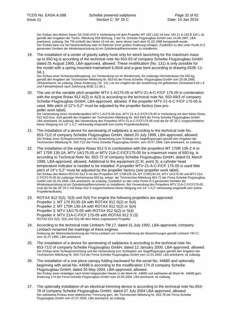
TCDS No. EASA.A.098 Scheibe powered sailplanes Section C: SF 25 C
Page 32 of 62 Date: 14 Jan 2016 Issue 11
Der Einbau des Motors Sauer SA 2100 H1S in Verbindung mit dem Propeller MT 150 L102-1A bzw. HO 11 A-150 B 102 L ist gemäß den Angaben der Techn. Mitteilung 653-60/Ausg. 2 der Fa. Scheibe Flugzeugbau GmbH vom 14.08.1997, LBA-anerkannt, zulässig. Die TM schließt den Motor 10 mit ein, wenn dieser nach dem 01.03.1998 hersgestellt wurde. Der Einbau kann nur bei Neuherstellung oder im Rahmen einer großen Änderung erfolgen. Zusätzlich zu den unter Punkt III.3 genannten Geräten der Mindestausrüstung ist ein Zylinderkopfthermometer zu installieren.
19. The installation of a center of gravity safety hook only for winch launching for the maximum mass up to 650 kg is according of the technical note No 653-63 of company Scheibe Flugzeugbau GmbH dated 25 August 1995, LBA-approved, allowed. These modification (No. 131) is only possible for the model with a spring mounted mainwheel 6.00x6 and a gear bent according to drawing 653E-11-S6.1. Der Einbau einer Schwerpunktkupplung, zur Verwendung nur im Windenstart, für zulässige Höchstmassen bis 650 kg, gemäß den Angaben der Technischen Mitteilung Nr. 653-63 der Firma Scheibe -Flugzeugbau-GmbH vom 25.08.1995, LBAanerkannt, ist zulässig. Diese Änderung ( Nr. 131 ) ist nur möglich bei der Ausführung mit gefedertem Zentralrad 6.00 x 6 und Fahrwerksbock nach Zeichnung 653E-11-S6.1.
20. The use of the variable pitch propeller MTV-1-A/175-05 or MTV-21-A-C-F/CF 175-05 in combination with the engine Rotax 912 A(2) or A(3) is according to the technical note No. 653-69/3 of company Scheibe Flugzeugbau GmbH, LBA-approved, allowed. If the propeller MTV-21-A-C-F/CF 175-05 is used, little pitch of 12°± 0,2° must be adjusted by the propeller factory (see pro- peller work label). Die Verwendung eines Verstellpropellers MTV-1-A/175-05 bzw. MTV-21-A-C-F/CF175-05 in Verbindung mit dem Motor Rotax 912 A(2) bzw. A(3) gemäß den Angaben der Technischen Mitteilung Nr. 653-69/3 der Firma Scheibe Flugzeugbau GmbH, LBA-anerkannt, ist zulässig. Bei Verwendung des Propellers MTV-21-A-C-F/CF175-05 muß die für SF 25 C vorgeschriebene kleine Steigung von 12° ± 0,2° werksseitig eingestellt sein (siehe Propellerlaufkarte).
21. The installation of a device for aerotowing of sailplanes is according to the technical note No. 653-71/2 of company Scheibe Flugzeugbau GmbH, dated 20 July 1999, LBA-approved, allowed. Der Einbau einer Schleppvorrichtung und die Verwendung zum Schlepp von Segelflugzeugen gemäß den Angaben der Technischen Mitteilung Nr. 653-71/2 der Firma Scheibe Flugzeugbau GmbH, vom 20.07.1999, LBA-anerkannt, ist zulässig.
22. The installation of the engine Rotax 912 S in combination with the propellers MT 170R 135-2 A or MT 175R 130-2A, MTV 1A/175-05 or MTV 21A-C-F/CF175-05 for a maximum mass of 650 kg, is according to Technical Note No. 653-72 of company Scheibe Flugzeugbau GmbH, dated 01 March 1999, LBA-approved, allowed. Additional to the equipment (C.III, point 3), a cylinder head temperature indicator is needed to be installed. If propeller MTV-21-A-C-F/CF 175-05 is used little pitch of 14°± 0,2° must be adjusted by the propeller factory (see propeller work label). Der Einbau des Motors ROTAX 912 S mit den Propellern MT 170R135-2A, MT 175R130-2A, MTV 1A/175-05 und MTV 21A-C-F/CF175-05 für zulässige Höchstmasse 650 kg, entspr. der Technischen Mitteilung 653-72 der Firma Scheibe Flugzeugbau GmbH vom 01.03.1999, LBA-anerkannt, ist zulässig. Zusätzlich zu den unter Punkt III.3 genannten Geräten der Mindestausrüstung ist ein Zylinderkopfthermometer zu installieren. Bei Verwendung des Propellers MTV 21A-C-F/CF175-05 muß die für die SF 25 C mit Rotax 912 S vorgeschriebene kleine Steigung von 14° ± 0,2° werksseitig eingestellt sein (siehe Propellerlaufkarte).
23. ROTAX 912 S(2), S(3) und S(4) For engine the following propellers are approved: Propeller 1: MT 170 R135-2A with ROTAX 912 S(2) or S(4) Propeller 2: MT 175R 130-2A with ROTAX 912 S(2) or S(4) Propeller 3: MTV 1A/175-05 with ROTAX 912 S(2) or S(4) Propeller 4: MTV 21A-C-F/CF 175-05 with ROTAX 912 S (3) ROTAX 912 S(2), S(3) und S(4) Mit dem Motor zugelassene Propeller
24. According to the technical note Limbach-TM 17, dated 31.July 1992, LBA-approved, company Limbach renamed the markings of there engines. Änderung der Motorenbezeichnung der Firma Limbach zur Vereinheitlichung der Bezeichnungen gemäß Limbach-TM 17, vom 31.07.1992, LBA-anerkannt.
25. The installation of a device for aerotowing of sailplanes is according to the technical note No. 653-71/2 of company Scheibe Flugzeugbau GmbH, dated 12 January 2000, LBA-approved, allowed. Der Einbau einer Schleppvorrichtung und die Verwendung zum Schleppen von Segelflugzeugen gemäß den Angaben der Technischen Mitteilung Nr. 653-71/3 der Firma Scheibe Flugzeugbau GmbH vom 12.01.2000, LBA-anerkannt, ist zulässig.
26. The installation of a one piece canopy folding backward for the serial No. 44685 and optionally beginning with serial No. 44698 is according to the modification 174 of company Scheibe Flugzeugbau GmbH, dated 20 May 2004, LBA-approved, allowed. Der Einbau einer einteiligen nach hinten klappenden Haube in die Werk-Nr. 44685 und wahlweise ab Werk-Nr. 44698 gem. Änderung 174 der Firma Scheibe Flugzeugbau GmbH vom 20.05.2004, LBA anerkannt, ist zulässig.
27. The optionally installation of an electrical trimming device is according to the technical note No.653-78 of company Scheibe Flugzeugbau GmbH, dated 07 July 2004 LBA-approved, allowed. Der wahlweise Einbau einer elektrischen Trimmung gem. der Technischen Mitteilung Nr. 653-78 der Firma Scheibe Flugzeugbau GmbH vom 07.07.2004, LBA anerkannt, ist zulässig.
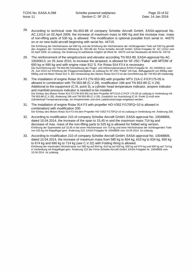
TCDS No. EASA.A.098 Scheibe powered sailplanes Section C: SF 25 C
Page 33 of 62 Date: 14 Jan 2016 Issue 11
28. According to technical note No.653-88 of company Scheibe Aircraft GmbH, EASA-approval No. AC.11014 on 02.April 2009, the increase of maximum mass to 690 Kg and the increase max. mass of non-lifting parts of 530 kg, is allowed. The modification is optional possible from serial nr. 44370 on or on new build aircraft beginning with serial No. 44719.
Die Erhöhung der Höchstmasse auf 690 Kg und die Erhöhung der Höchstmasse der nichttragenden Teile auf 530 Kg gemäß den Angaben der Technischen Mitteilung Nr. 653-88 der Firma Scheibe Aircraft GmbH, EASA-Freigabe Nr. AC.11014 vom 02.April 2009, ist zulässig. Die Änderung ist wahlweise möglich ab Werk-Nr. 44370 und bei Neubauten ab Werk-Nr. 44719.
29. The reinforcement of the wingstructure and elevator according TN 653-89, EASA-approval No.AC. 10030613, on 25.June 2010, to increase the airspeed, is allowed for SF-25C-“Falke” with MTOW of 650 kg or 690 kg and with engine rotax 912 S. For Rotax 914 F3 it is necessary. Die Durchführung der TM 653-89 (Verstärkung der Flügel- und Höhenruderstruktur) EASA-Freigabe Nr. AC.10030613, vom 25. Juni 2010 zur Erhöhung der Fluggeschwindigkeit, ist zulässig für SF-25C-“Falke” mit max. Abfluggewicht von 650kg oder 690kg und mit Motor Rotax 912 S. Bei Verwendung des Motors Rotax 914 F3 ist die Durchführung der TM 653-89 notwendig.
30. The installation of engine Rotax 914 F3 (TN 653-90) with propeller MTV 21A-C-F/CF175-05 is allowed in combination with TN 563-88 (C.V.28), modification 196 and TN 653-89 (C.V.29). Additional to the equipment (C.III, point 3), a cylinder head temperature indicator, ampere indicator and manifold pressure indicator is needed to be installed. Der Einbau des Motors Rotax 914 F3 (TM 653-90) mit dem Propeller MTV21A-C-F/CF 175-05 ist zulässig in Verbindung mit TM 563-88 (C.V.28), Änderung 196 und TM 653-89 (C.V.29). Zusätzlich zur Ausrüstung (C.III, Punkt 3) muß eine Zylinderkopf-Temperaturanzeige, ein Ampèremeter und eine Ladedruckanzeige eingebaut werden.
31.
The installation of engine Rotax 914 F3 with propeller HO-V352 F/170FQ+10 is allowed in combination| with modification 200. Der Einbau des Motors Rotax 914 F3 mit dem Propeller HO-V352 F/170FQ+10 ist zulässig in Verbindung mit Änderung 200.
32.
According to modification 210 of company Scheibe Aircraft GmbH, EASA-approval No. 10048806, dated 10.04.2014, the increase of the span to 15,45 m and the maximum mass 714 kg and decrease of max. mass of the non-lifting parts to 525 kg is allowed for folded wing version. Erhöhung der Spannweite auf 15,45 m bei einer Höchstmasse von 714 kg und einer Höchstmasse der nichttragenden Teile von 525 kg mit Klappflügel gem. Änderung 210, EASA-Freigabe Nr 10048806 vom 10.04.2014. ist zulässig .
33.
According to modification 210 of company Scheibe Aircraft GmbH, EASA-approval No. 10048806, dated 10.04.2014, the increase of maximum mass from 580 kg to 604 kg, 610 kg to 634 kg, 650 kg to 674 kg and 690 kg to 714 kg (see C.V.32) with Folding Wing is allowed. Erhöhung der maximalen Höchstmasse von 580 kg auf 604 kg, 610 kg auf 634 kg, 650 kg auf 674 kg und 690 kg auf 714 kg in Verbindung mit Klappflügel gem. Änderung 210 der Firme Scheibe Aircraft GmbH, EASA-Freigabe Nr. 10048806 vom 10.04.2014 ist zulässig.
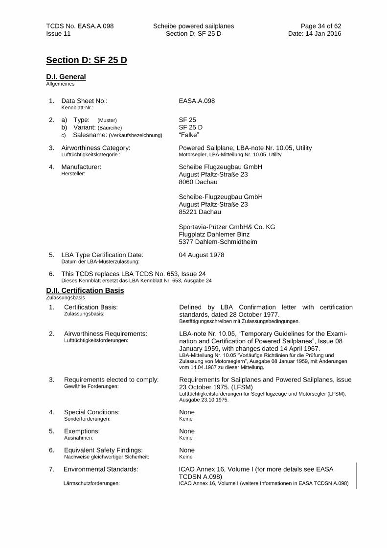
TCDS No. EASA.A.098 Scheibe powered sailplanes Section D: SF 25 D
Page 34 of 62 Date: 14 Jan 2016 Issue 11
Section D: SF 25 D
D.I. General Allgemeines
1. Data Sheet No.: Kennblatt-Nr.:
EASA.A.098
2. a) Type: (Muster) b) Variant: (Baureihe)
c) Salesname: (Verkaufsbezeichnung)
SF 25 SF 25 D “Falke”
3. Airworthiness Category: Lufttüchtigkeitskategorie :
Powered Sailplane, LBA-note Nr. 10.05, Utility Motorsegler, LBA-Mitteilung Nr. 10.05 Utility
4. Manufacturer: Hersteller:
Scheibe Flugzeugbau GmbH August Pfaltz-Straße 23 8060 Dachau Scheibe-Flugzeugbau GmbH August Pfaltz-Straße 23 85221 Dachau Sportavia-Pützer GmbH& Co. KG Flugplatz Dahlemer Binz 5377 Dahlem-Schmidtheim
5. LBA Type Certification Date: Datum der LBA-Musterzulassung:
04 August 1978
6. This TCDS replaces LBA TCDS No. 653, Issue 24 Dieses Kennblatt ersetzt das LBA Kennblatt Nr. 653, Ausgabe 24
D.II. Certification Basis Zulassungsbasis
1. Certification Basis: Zulassungsbasis:
Defined by LBA Confirmation letter with certification standards, dated 28 October 1977. Bestätigungsschreiben mit Zulassungsbedingungen.
2. Airworthiness Requirements: Lufttüchtigkeitsforderungen:
LBA-note Nr. 10.05, “Temporary Guidelines for the Exami- nation and Certification of Powered Sailplanes”, Issue 08 January 1959, with changes dated 14 April 1967. LBA-Mitteilung Nr. 10.05 “Vorläufige Richtlinien für die Prüfung und Zulassung von Motorseglern”, Ausgabe 08 Januar 1959, mit Änderungen vom 14.04.1967 zu dieser Mitteilung.
3. Requirements elected to comply: Gewählte Forderungen:
Requirements for Sailplanes and Powered Sailplanes, issue 23 October 1975. (LFSM) Lufttüchtigkeitsforderungen für Segelflugzeuge und Motorsegler (LFSM), Ausgabe 23.10.1975.
4. Special Conditions: Sonderforderungen:
None Keine
5. Exemptions: Ausnahmen:
None Keine
6. Equivalent Safety Findings: Nachweise gleichwertiger Sicherheit:
None Keine
7. Environmental Standards: Lärmschutzforderungen:
ICAO Annex 16, Volume I (for more details see EASA TCDSN A.098) ICAO Annex 16, Volume I (weitere Informationen in EASA TCDSN A.098)
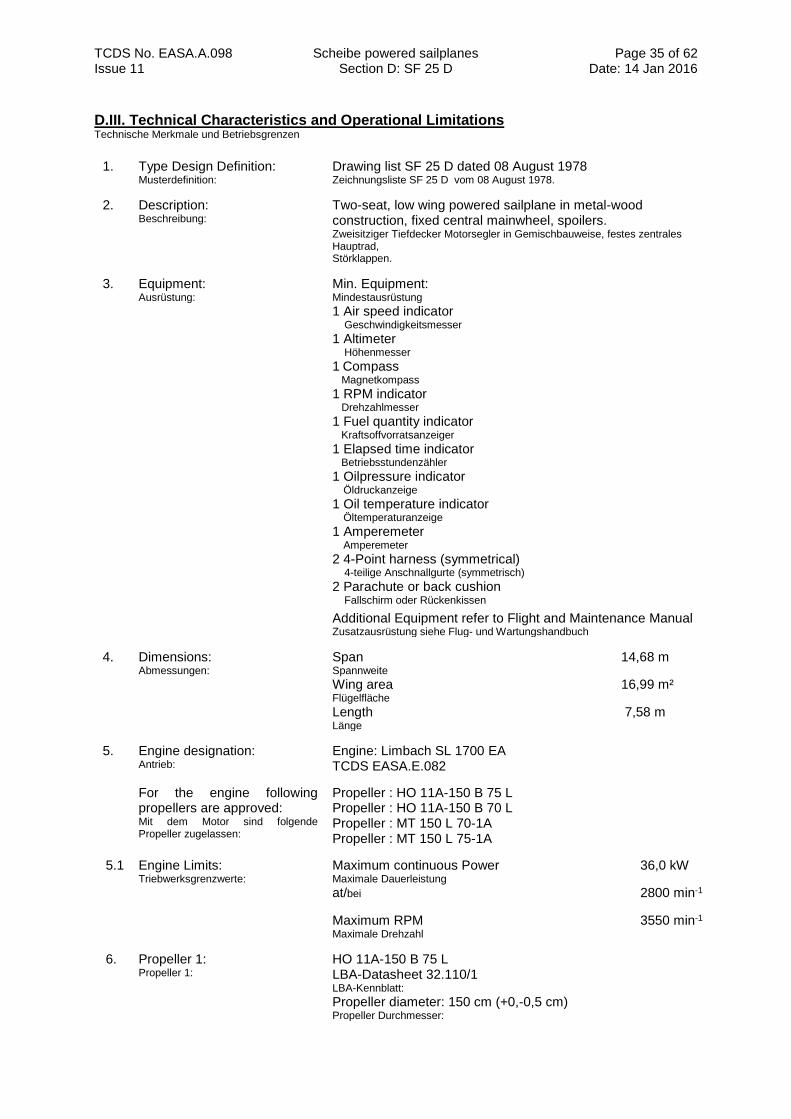
TCDS No. EASA.A.098 Scheibe powered sailplanes Section D: SF 25 D
Page 35 of 62 Date: 14 Jan 2016 Issue 11
D.III. Technical Characteristics and Operational Limitations Technische Merkmale und Betriebsgrenzen
1. Type Design Definition: Musterdefinition:
Drawing list SF 25 D dated 08 August 1978 Zeichnungsliste SF 25 D vom 08 August 1978.
2. Description: Beschreibung:
Two-seat, low wing powered sailplane in metal-wood construction, fixed central mainwheel, spoilers. Zweisitziger Tiefdecker Motorsegler in Gemischbauweise, festes zentrales Hauptrad, Störklappen.
3. Equipment: Ausrüstung:
Min. Equipment: Mindestausrüstung
1 Air speed indicator Geschwindigkeitsmesser
1 Altimeter Höhenmesser
1 Compass
Magnetkompass
1 RPM indicator Drehzahlmesser
1 Fuel quantity indicator Kraftsoffvorratsanzeiger
1 Elapsed time indicator Betriebsstundenzähler
1 Oilpressure indicator Öldruckanzeige
1 Oil temperature indicator Öltemperaturanzeige
1 Amperemeter Amperemeter
2 4-Point harness (symmetrical) 4-teilige Anschnallgurte (symmetrisch)
2 Parachute or back cushion Fallschirm oder Rückenkissen
Additional Equipment refer to Flight and Maintenance Manual Zusatzausrüstung siehe Flug- und Wartungshandbuch
4. Dimensions: Abmessungen:
Span 14,68 m Spannweite
Wing area 16,99 m² Flügelfläche
Length 7,58 m Länge
5. Engine designation: Antrieb:
Engine: Limbach SL 1700 EA TCDS EASA.E.082
For the engine following propellers are approved: Mit dem Motor sind folgende Propeller zugelassen:
Propeller : HO 11A-150 B 75 L Propeller : HO 11A-150 B 70 L Propeller : MT 150 L 70-1A Propeller : MT 150 L 75-1A
5.1 Engine Limits: Triebwerksgrenzwerte:
Maximum continuous Power 36,0 kW Maximale Dauerleistung
at/bei 2800 min-1
Maximum RPM 3550 min-1
Maximale Drehzahl
6. Propeller 1: Propeller 1:
HO 11A-150 B 75 L LBA-Datasheet 32.110/1 LBA-Kennblatt: Propeller diameter: 150 cm (+0,-0,5 cm) Propeller Durchmesser:
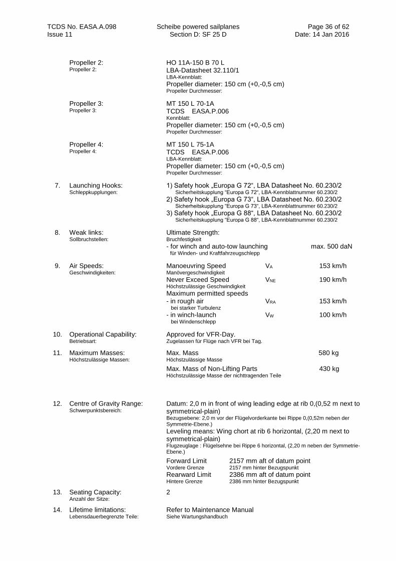
TCDS No. EASA.A.098 Scheibe powered sailplanes Section D: SF 25 D
Page 36 of 62 Date: 14 Jan 2016 Issue 11
Propeller 2: Propeller 2:
HO 11A-150 B 70 L LBA-Datasheet 32.110/1 LBA-Kennblatt: Propeller diameter: 150 cm (+0,-0,5 cm) Propeller Durchmesser:
Propeller 3: Propeller 3:
MT 150 L 70-1A TCDS EASA.P.006 Kennblatt: Propeller diameter: 150 cm (+0,-0,5 cm) Propeller Durchmesser:
Propeller 4: Propeller 4:
MT 150 L 75-1A TCDS EASA.P.006 LBA-Kennblatt: Propeller diameter: 150 cm (+0,-0,5 cm) Propeller Durchmesser:
7. Launching Hooks: Schleppkupplungen:
1) Safety hook „Europa G 72“, LBA Datasheet No. 60.230/2
Sicherheitskupplung “Europa G 72“, LBA-Kennblattnummer 60.230/2 2) Safety hook „Europa G 73“, LBA Datasheet No. 60.230/2
Sicherheitskupplung “Europa G 73“, LBA-Kennblattnummer 60.230/2 3) Safety hook „Europa G 88“, LBA Datasheet No. 60.230/2
Sicherheitskupplung “Europa G 88“, LBA-Kennblattnummer 60.230/2
8. Weak links: Sollbruchstellen:
Ultimate Strength: Bruchfestigkeit - for winch and auto-tow launching max. 500 daN für Winden- und Kraftfahrzeugschlepp
9. Air Speeds: Geschwindigkeiten:
Manoeuvring Speed VA 153 km/h Manövergeschwindigkeit Never Exceed Speed VNE 190 km/h Höchstzulässige Geschwindigkeit
Maximum permitted speeds - in rough air VRA 153 km/h bei starker Turbulenz
- in winch-launch VW 100 km/h bei Windenschlepp
10. Operational Capability: Betriebsart:
Approved for VFR-Day. Zugelassen für Flüge nach VFR bei Tag.
11. Maximum Masses: Höchstzulässige Massen:
Max. Mass 580 kg Höchstzulässige Masse
Max. Mass of Non-Lifting Parts 430 kg
Höchstzulässige Masse der nichttragenden Teile
12. Centre of Gravity Range: Schwerpunktsbereich:
Datum: 2,0 m in front of wing leading edge at rib 0,(0,52 m next to symmetrical-plain) Bezugsebene: 2,0 m vor der Flügelvorderkante bei Rippe 0,(0,52m neben der Symmetrie-Ebene.)
Leveling means: Wing chort at rib 6 horizontal, (2,20 m next to symmetrical-plain) Flugzeuglage : Flügelsehne bei Rippe 6 horizontal, (2,20 m neben der Symmetrie-Ebene.)
Forward Limit 2157 mm aft of datum point Vordere Grenze 2157 mm hinter Bezugspunkt Rearward Limit 2386 mm aft of datum point Hintere Grenze 2386 mm hinter Bezugspunkt
13. Seating Capacity: Anzahl der Sitze:
2
14. Lifetime limitations: Lebensdauerbegrenzte Teile:
Refer to Maintenance Manual Siehe Wartungshandbuch
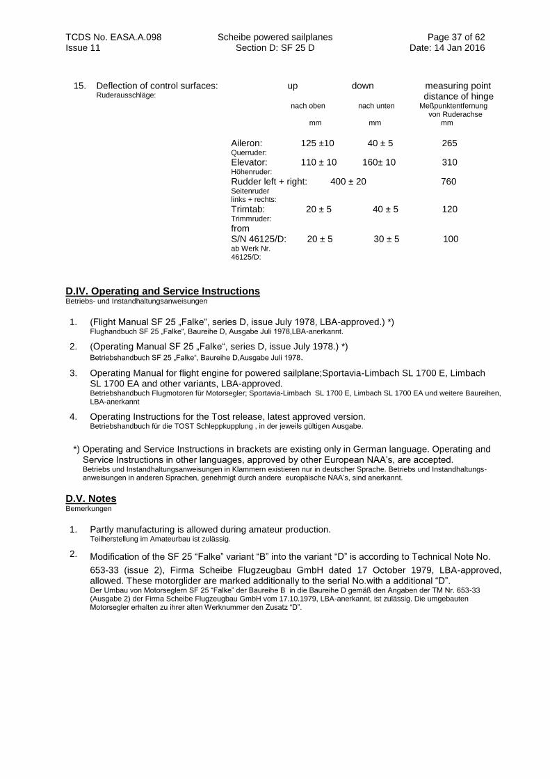
TCDS No. EASA.A.098 Scheibe powered sailplanes Section D: SF 25 D
Page 37 of 62 Date: 14 Jan 2016 Issue 11
15. Deflection of control surfaces: Ruderausschläge:
up down measuring point distance of hinge nach oben nach unten Meßpunktentfernung von Ruderachse mm mm mm
Aileron: 125 ±10 40 ± 5 265 Querruder:
Elevator: 110 ± 10 160± 10 310 Höhenruder:
Rudder left + right: 400 ± 20 760 Seitenruder links + rechts:
Trimtab: 20 ± 5 40 ± 5 120 Trimmruder:
from S/N 46125/D: 20 ± 5 30 ± 5 100 ab Werk Nr. 46125/D:
D.IV. Operating and Service Instructions Betriebs- und Instandhaltungsanweisungen
1. (Flight Manual SF 25 „Falke“, series D, issue July 1978, LBA-approved.) *) Flughandbuch SF 25 „Falke“, Baureihe D, Ausgabe Juli 1978,LBA-anerkannt.
2. (Operating Manual SF 25 „Falke“, series D, issue July 1978.) *) Betriebshandbuch SF 25 „Falke“, Baureihe D,Ausgabe Juli 1978.
3. Operating Manual for flight engine for powered sailplane;Sportavia-Limbach SL 1700 E, Limbach SL 1700 EA and other variants, LBA-approved. Betriebshandbuch Flugmotoren für Motorsegler; Sportavia-Limbach SL 1700 E, Limbach SL 1700 EA und weitere Baureihen, LBA-anerkannt
4. Operating Instructions for the Tost release, latest approved version. Betriebshandbuch für die TOST Schleppkupplung , in der jeweils gültigen Ausgabe.
*) Operating and Service Instructions in brackets are existing only in German language. Operating and
Service Instructions in other languages, approved by other European NAA’s, are accepted. Betriebs und Instandhaltungsanweisungen in Klammern existieren nur in deutscher Sprache. Betriebs und Instandhaltungs- anweisungen in anderen Sprachen, genehmigt durch andere europäische NAA’s, sind anerkannt.
D.V. Notes Bemerkungen
1. Partly manufacturing is allowed during amateur production. Teilherstellung im Amateurbau ist zulässig.
2. Modification of the SF 25 “Falke” variant “B” into the variant “D” is according to Technical Note No.
653-33 (issue 2), Firma Scheibe Flugzeugbau GmbH dated 17 October 1979, LBA-approved, allowed. These motorglider are marked additionally to the serial No.with a additional “D”. Der Umbau von Motorseglern SF 25 “Falke” der Baureihe B in die Baureihe D gemäß den Angaben der TM Nr. 653-33 (Ausgabe 2) der Firma Scheibe Flugzeugbau GmbH vom 17.10.1979, LBA-anerkannt, ist zulässig. Die umgebauten Motorsegler erhalten zu ihrer alten Werknummer den Zusatz “D”.
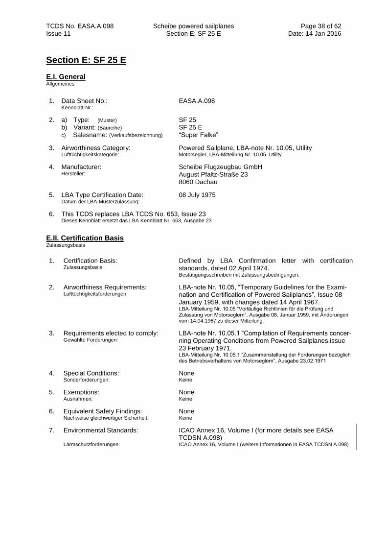
TCDS No. EASA.A.098 Scheibe powered sailplanes Section E: SF 25 E
Page 38 of 62 Date: 14 Jan 2016 Issue 11
Section E: SF 25 E
E.I. General Allgemeines
1. Data Sheet No.: Kennblatt-Nr.:
EASA.A.098
2. a) Type: (Muster) b) Variant: (Baureihe)
c) Salesname: (Verkaufsbezeichnung)
SF 25 SF 25 E “Super Falke”
3. Airworthiness Category: Lufttüchtigkeitskategorie:
Powered Sailplane, LBA-note Nr. 10.05, Utility Motorsegler, LBA-Mitteilung Nr. 10.05 Utility
4. Manufacturer: Hersteller:
Scheibe Flugzeugbau GmbH August Pfaltz-Straße 23 8060 Dachau
5. LBA Type Certification Date: Datum der LBA-Musterzulassung:
08 July 1975
6. This TCDS replaces LBA TCDS No. 653, Issue 23 Dieses Kennblatt ersetzt das LBA Kennblatt Nr. 653, Ausgabe 23
E.II. Certification Basis Zulassungsbasis
1. Certification Basis: Zulassungsbasis:
Defined by LBA Confirmation letter with certification standards, dated 02 April 1974. Bestätigungsschreiben mit Zulassungsbedingungen.
2. Airworthiness Requirements: Lufttüchtigkeitsforderungen:
LBA-note Nr. 10.05, “Temporary Guidelines for the Exami- nation and Certification of Powered Sailplanes”, Issue 08 January 1959, with changes dated 14 April 1967. LBA-Mitteilung Nr. 10.05 “Vorläufige Richtlinien für die Prüfung und Zulassung von Motorseglern”, Ausgabe 08. Januar 1959, mit Änderungen vom 14.04.1967 zu dieser Mitteilung.
3. Requirements elected to comply: Gewählte Forderungen:
LBA-note Nr. 10.05.1 “Compilation of Requirements concer- ning Operating Conditions from Powered Sailplanes,issue 23 February 1971. LBA-Mitteilung Nr. 10.05.1 “Zusammenstellung der Forderungen bezüglich des Betriebsverhaltens von Motorseglern”, Ausgabe 23.02.1971
4. Special Conditions: Sonderforderungen:
None Keine
5. Exemptions: Ausnahmen:
None Keine
6. Equivalent Safety Findings: Nachweise gleichwertiger Sicherheit:
None Keine
7. Environmental Standards: Lärmschutzforderungen:
ICAO Annex 16, Volume I (for more details see EASA TCDSN A.098) ICAO Annex 16, Volume I (weitere Informationen in EASA TCDSN A.098)
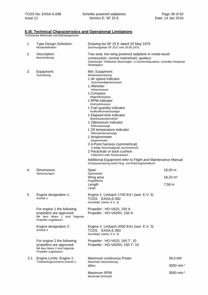
TCDS No. EASA.A.098 Scheibe powered sailplanes Section E: SF 25 E
Page 39 of 62 Date: 14 Jan 2016 Issue 11
E.III. Technical Characteristics and Operational Limitations Technische Merkmale und Betriebsgrenzen
1. Type Design Definition: Musterdefinition:
Drawing list SF 25 E dated 20 May 1975 Zeichnungsliste SF 25 E vom 20.05.1975.
2. Description: Beschreibung:
Two-seat, low wing powered sailplane in metal-wood construction, central mainwheel, spoilers. Zweisitziger Tiefdecker Motorsegler in Gemischbauweise, zentrales Hauptrad, Störklappen.
3. Equipment: Ausrüstung:
Min. Equipment: Mindestausrüstung
1 Air speed indicator Geschwindigkeitsmesser
1 Altimeter Höhenmesser
1 Compass
Magnetkompass
1 RPM indicator Drehzahlmesser
1 Fuel quantity indicator Kraftsoffvorratsanzeiger
1 Elapsed time indicator Betriebsstundenzähler
1 Oilpressure indicator Öldruckanzeige
1 Oil temperature indicator Öltemperaturanzeige
1 Amperemeter Amperemeter
2 4-Point harness (symmetrical) 4-teilige Anschnallgurte (symmetrisch)
2 Parachute or back cushion Fallschirm oder Rückenkissen
Additional Equipment refer to Flight and Maintenance Manual Zusatzausrüstung siehe Flug- und Wartungshandbuch
4. Dimensions: Abmessungen:
Span 18,00 m Spannweite
Wing area 18,20 m² Flügelfläche
Length 7,58 m Länge
5. Engine designation 1: Antrieb 1:
Engine 1: Limbach 1700 EA I (see: E.V. 2) TCDS EASA.E.082 Kennblatt: (siehe: E.V. 2)
For engine 1 the following propellers are approved: Mit dem Motor 1 sind folgende Propeller zugelassen:
Propeller : HO-V62/L 150 A Propeller : HO-V62R/L 150 A
Engine designation 2: Antrieb 2:
Engine 2: Limbach 2000 EA1 (see: E.V. 3) TCDS EASA.E.083 Kennblatt: (siehe: E.V. 3)
For engine 2 the following propellers are approved: Mit dem Motor 2 sind folgende Propeller zugelassen:
Propeller : HO-V62/L 160 T- 10 Propeller : HO-V62R/L 160 T- 10
5.1 Engine Limits: Engine 1: Triebwerksgrenzwerte,Antrieb 1:
Maximum continuous Power 39,0 kW Maximale Dauerleistung
at/bei 3050 min-1
Maximum RPM 3550 min-1
Maximale Drehzahl
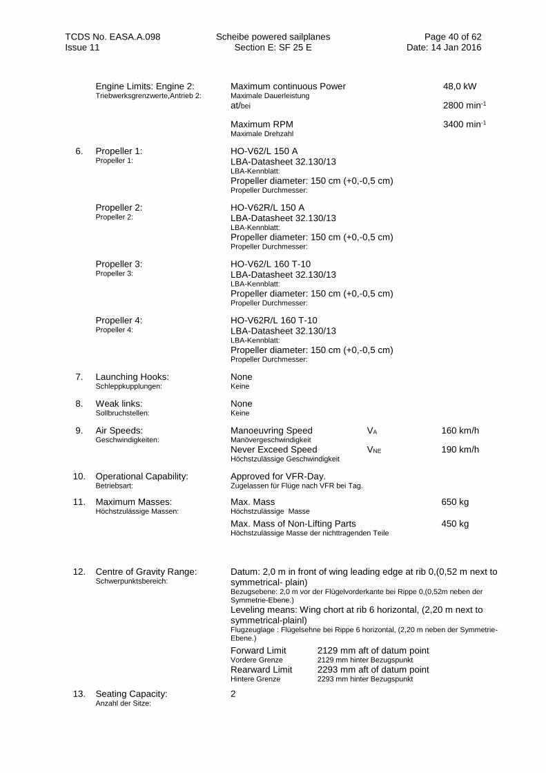
TCDS No. EASA.A.098 Scheibe powered sailplanes Section E: SF 25 E
Page 40 of 62 Date: 14 Jan 2016 Issue 11
Engine Limits: Engine 2: Triebwerksgrenzwerte,Antrieb 2:
Maximum continuous Power 48,0 kW Maximale Dauerleistung
at/bei 2800 min-1
Maximum RPM 3400 min-1
Maximale Drehzahl
6. Propeller 1: Propeller 1:
HO-V62/L 150 A LBA-Datasheet 32.130/13 LBA-Kennblatt: Propeller diameter: 150 cm (+0,-0,5 cm) Propeller Durchmesser:
Propeller 2: Propeller 2:
HO-V62R/L 150 A LBA-Datasheet 32.130/13 LBA-Kennblatt: Propeller diameter: 150 cm (+0,-0,5 cm) Propeller Durchmesser:
Propeller 3: Propeller 3:
HO-V62/L 160 T-10 LBA-Datasheet 32.130/13 LBA-Kennblatt: Propeller diameter: 150 cm (+0,-0,5 cm) Propeller Durchmesser:
Propeller 4: Propeller 4:
HO-V62R/L 160 T-10 LBA-Datasheet 32.130/13 LBA-Kennblatt: Propeller diameter: 150 cm (+0,-0,5 cm) Propeller Durchmesser:
7. Launching Hooks: Schleppkupplungen:
None Keine
8. Weak links: Sollbruchstellen:
None Keine
9. Air Speeds: Geschwindigkeiten:
Manoeuvring Speed VA 160 km/h Manövergeschwindigkeit Never Exceed Speed VNE 190 km/h Höchstzulässige Geschwindigkeit
10. Operational Capability: Betriebsart:
Approved for VFR-Day. Zugelassen für Flüge nach VFR bei Tag.
11. Maximum Masses: Höchstzulässige Massen:
Max. Mass 650 kg Höchstzulässige Masse
Max. Mass of Non-Lifting Parts 450 kg
Höchstzulässige Masse der nichttragenden Teile
12. Centre of Gravity Range: Schwerpunktsbereich:
Datum: 2,0 m in front of wing leading edge at rib 0,(0,52 m next to symmetrical- plain) Bezugsebene: 2,0 m vor der Flügelvorderkante bei Rippe 0,(0,52m neben der Symmetrie-Ebene.)
Leveling means: Wing chort at rib 6 horizontal, (2,20 m next to symmetrical-plainl) Flugzeuglage : Flügelsehne bei Rippe 6 horizontal, (2,20 m neben der Symmetrie-Ebene.)
Forward Limit 2129 mm aft of datum point Vordere Grenze 2129 mm hinter Bezugspunkt Rearward Limit 2293 mm aft of datum point Hintere Grenze 2293 mm hinter Bezugspunkt
13. Seating Capacity: Anzahl der Sitze:
2
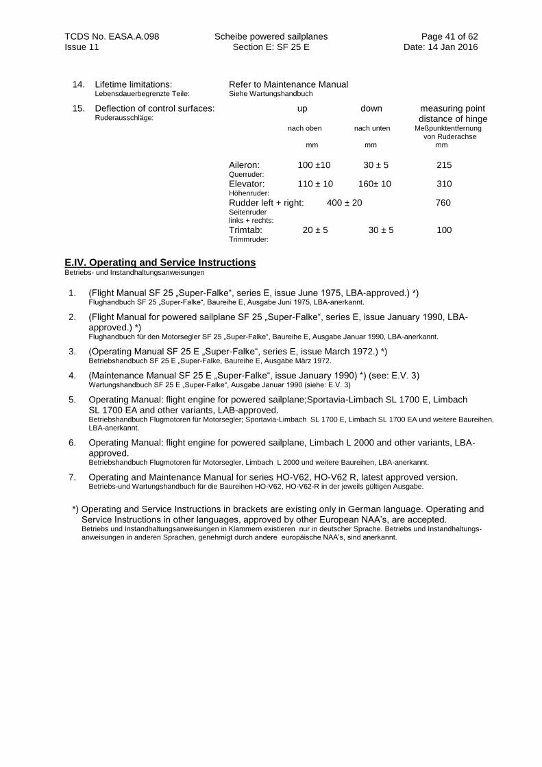
TCDS No. EASA.A.098 Scheibe powered sailplanes Section E: SF 25 E
Page 41 of 62 Date: 14 Jan 2016 Issue 11
14. Lifetime limitations: Lebensdauerbegrenzte Teile:
Refer to Maintenance Manual Siehe Wartungshandbuch
15. Deflection of control surfaces: Ruderausschläge:
up down measuring point distance of hinge nach oben nach unten Meßpunktentfernung von Ruderachse mm mm mm
Aileron: 100 ±10 30 ± 5 215 Querruder:
Elevator: 110 ± 10 160± 10 310 Höhenruder:
Rudder left + right: 400 ± 20 760 Seitenruder links + rechts:
Trimtab: 20 ± 5 30 ± 5 100 Trimmruder:
E.IV. Operating and Service Instructions Betriebs- und Instandhaltungsanweisungen
1. (Flight Manual SF 25 „Super-Falke“, series E, issue June 1975, LBA-approved.) *) Flughandbuch SF 25 „Super-Falke“, Baureihe E, Ausgabe Juni 1975, LBA-anerkannt.
2. (Flight Manual for powered sailplane SF 25 „Super-Falke“, series E, issue January 1990, LBA-approved.) *) Flughandbuch für den Motorsegler SF 25 „Super-Falke“, Baureihe E, Ausgabe Januar 1990, LBA-anerkannt.
3. (Operating Manual SF 25 E „Super-Falke“, series E, issue March 1972.) *) Betriebshandbuch SF 25 E „Super-Falke, Baureihe E, Ausgabe März 1972.
4. (Maintenance Manual SF 25 E „Super-Falke“, issue January 1990) *) (see: E.V. 3) Wartungshandbuch SF 25 E „Super-Falke“, Ausgabe Januar 1990 (siehe: E.V. 3)
5. Operating Manual: flight engine for powered sailplane;Sportavia-Limbach SL 1700 E, Limbach SL 1700 EA and other variants, LAB-approved. Betriebshandbuch Flugmotoren für Motorsegler; Sportavia-Limbach SL 1700 E, Limbach SL 1700 EA und weitere Baureihen, LBA-anerkannt.
6. Operating Manual: flight engine for powered sailplane, Limbach L 2000 and other variants, LBA-approved. Betriebshandbuch Flugmotoren für Motorsegler, Limbach L 2000 und weitere Baureihen, LBA-anerkannt.
7. Operating and Maintenance Manual for series HO-V62, HO-V62 R, latest approved version. Betriebs-und Wartungshandbuch für die Baureihen HO-V62, HO-V62-R in der jeweils gültigen Ausgabe.
*) Operating and Service Instructions in brackets are existing only in German language. Operating and
Service Instructions in other languages, approved by other European NAA’s, are accepted. Betriebs und Instandhaltungsanweisungen in Klammern existieren nur in deutscher Sprache. Betriebs und Instandhaltungs- anweisungen in anderen Sprachen, genehmigt durch andere europäische NAA’s, sind anerkannt.
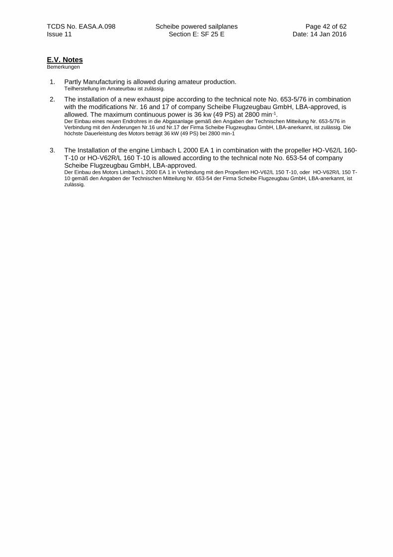
TCDS No. EASA.A.098 Scheibe powered sailplanes Section E: SF 25 E
Page 42 of 62 Date: 14 Jan 2016 Issue 11
E.V. Notes Bemerkungen
1. Partly Manufacturing is allowed during amateur production. Teilherstellung im Amateurbau ist zulässig.
2. The installation of a new exhaust pipe according to the technical note No. 653-5/76 in combination with the modifications Nr. 16 and 17 of company Scheibe Flugzeugbau GmbH, LBA-approved, is allowed. The maximum continuous power is 36 kw (49 PS) at 2800 min-1. Der Einbau eines neuen Endrohres in die Abgasanlage gemäß den Angaben der Technischen Mitteilung Nr. 653-5/76 in Verbindung mit den Änderungen Nr.16 und Nr.17 der Firma Scheibe Flugzeugbau GmbH, LBA-anerkannt, ist zulässig. Die höchste Dauerleistung des Motors beträgt 36 kW (49 PS) bei 2800 min-1
3. The Installation of the engine Limbach L 2000 EA 1 in combination with the propeller HO-V62/L 160- T-10 or HO-V62R/L 160 T-10 is allowed according to the technical note No. 653-54 of company Scheibe Flugzeugbau GmbH, LBA-approved. Der Einbau des Motors Limbach L 2000 EA 1 in Verbindung mit den Propellern HO-V62/L 150 T-10, oder HO-V62R/L 150 T-10 gemäß den Angaben der Technischen Mitteilung Nr. 653-54 der Firma Scheibe Flugzeugbau GmbH, LBA-anerkannt, ist zulässig.
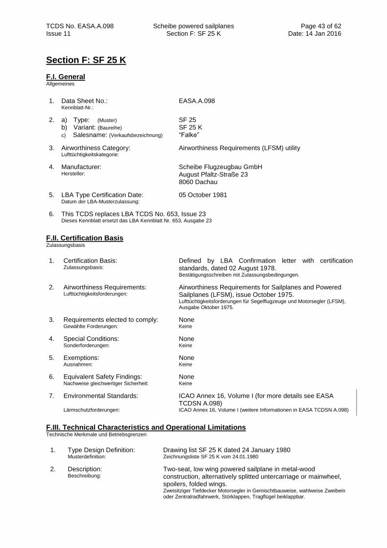
TCDS No. EASA.A.098 Scheibe powered sailplanes Section F: SF 25 K
Page 43 of 62 Date: 14 Jan 2016 Issue 11
Section F: SF 25 K
F.I. General Allgemeines
1. Data Sheet No.: Kennblatt-Nr.:
EASA.A.098
2. a) Type: (Muster) b) Variant: (Baureihe)
c) Salesname: (Verkaufsbezeichnung)
SF 25 SF 25 K “Falke”
3. Airworthiness Category: Lufttüchtigkeitskategorie:
Airworthiness Requirements (LFSM) utility
4. Manufacturer: Hersteller:
Scheibe Flugzeugbau GmbH August Pfaltz-Straße 23 8060 Dachau
5. LBA Type Certification Date: Datum der LBA-Musterzulassung:
05 October 1981
6. This TCDS replaces LBA TCDS No. 653, Issue 23 Dieses Kennblatt ersetzt das LBA Kennblatt Nr. 653, Ausgabe 23
F.II. Certification Basis Zulassungsbasis
1. Certification Basis: Zulassungsbasis:
Defined by LBA Confirmation letter with certification standards, dated 02 August 1978. Bestätigungsschreiben mit Zulassungsbedingungen.
2. Airworthiness Requirements: Lufttüchtigkeitsforderungen:
Airworthiness Requirements for Sailplanes and Powered Sailplanes (LFSM), issue October 1975. Lufttüchtigkeitsforderungen für Segelflugzeuge und Motorsegler (LFSM), Ausgabe Oktober 1975.
3. Requirements elected to comply: Gewählte Forderungen:
None Keine
4. Special Conditions: Sonderforderungen:
None Keine
5. Exemptions: Ausnahmen:
None Keine
6. Equivalent Safety Findings: Nachweise gleichwertiger Sicherheit:
None
Keine
7. Environmental Standards: Lärmschutzforderungen:
ICAO Annex 16, Volume I (for more details see EASA TCDSN A.098) ICAO Annex 16, Volume I (weitere Informationen in EASA TCDSN A.098)
F.III. Technical Characteristics and Operational Limitations Technische Merkmale und Betriebsgrenzen
1. Type Design Definition: Musterdefinition:
Drawing list SF 25 K dated 24 January 1980 Zeichnungsliste SF 25 K vom 24.01.1980
2. Description: Beschreibung:
Two-seat, low wing powered sailplane in metal-wood construction, alternatively splitted untercarriage or mainwheel, spoilers, folded wings. Zweisitziger Tiefdecker Motorsegler in Gemischtbauweise, wahlweise Zweibein oder Zentralradfahrwerk, Störklappen, Tragflügel beiklappbar.
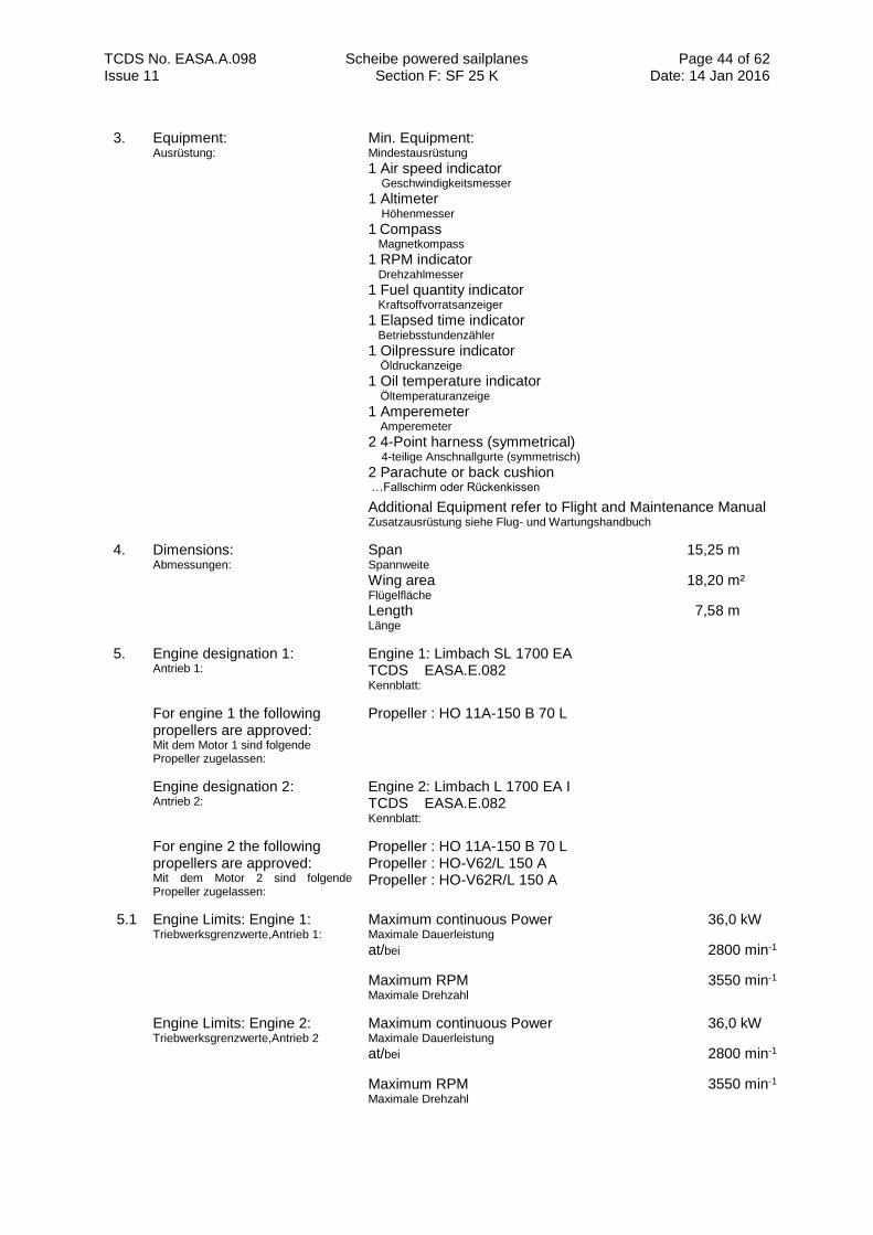
TCDS No. EASA.A.098 Scheibe powered sailplanes Section F: SF 25 K
Page 44 of 62 Date: 14 Jan 2016 Issue 11
3. Equipment: Ausrüstung:
Min. Equipment: Mindestausrüstung
1 Air speed indicator Geschwindigkeitsmesser
1 Altimeter Höhenmesser
1 Compass
Magnetkompass
1 RPM indicator Drehzahlmesser
1 Fuel quantity indicator Kraftsoffvorratsanzeiger
1 Elapsed time indicator Betriebsstundenzähler
1 Oilpressure indicator Öldruckanzeige
1 Oil temperature indicator Öltemperaturanzeige
1 Amperemeter Amperemeter
2 4-Point harness (symmetrical) 4-teilige Anschnallgurte (symmetrisch)
2 Parachute or back cushion …Fallschirm oder Rückenkissen
Additional Equipment refer to Flight and Maintenance Manual Zusatzausrüstung siehe Flug- und Wartungshandbuch
4. Dimensions: Abmessungen:
Span 15,25 m Spannweite
Wing area 18,20 m² Flügelfläche
Length 7,58 m Länge
5. Engine designation 1: Antrieb 1:
Engine 1: Limbach SL 1700 EA TCDS EASA.E.082 Kennblatt:
For engine 1 the following propellers are approved: Mit dem Motor 1 sind folgende Propeller zugelassen:
Propeller : HO 11A-150 B 70 L
Engine designation 2: Antrieb 2:
Engine 2: Limbach L 1700 EA I TCDS EASA.E.082 Kennblatt:
For engine 2 the following propellers are approved: Mit dem Motor 2 sind folgende Propeller zugelassen:
Propeller : HO 11A-150 B 70 L Propeller : HO-V62/L 150 A Propeller : HO-V62R/L 150 A
5.1 Engine Limits: Engine 1: Triebwerksgrenzwerte,Antrieb 1:
Maximum continuous Power 36,0 kW Maximale Dauerleistung
at/bei 2800 min-1
Maximum RPM 3550 min-1
Maximale Drehzahl
Engine Limits: Engine 2: Triebwerksgrenzwerte,Antrieb 2
Maximum continuous Power 36,0 kW Maximale Dauerleistung
at/bei 2800 min-1
Maximum RPM 3550 min-1
Maximale Drehzahl
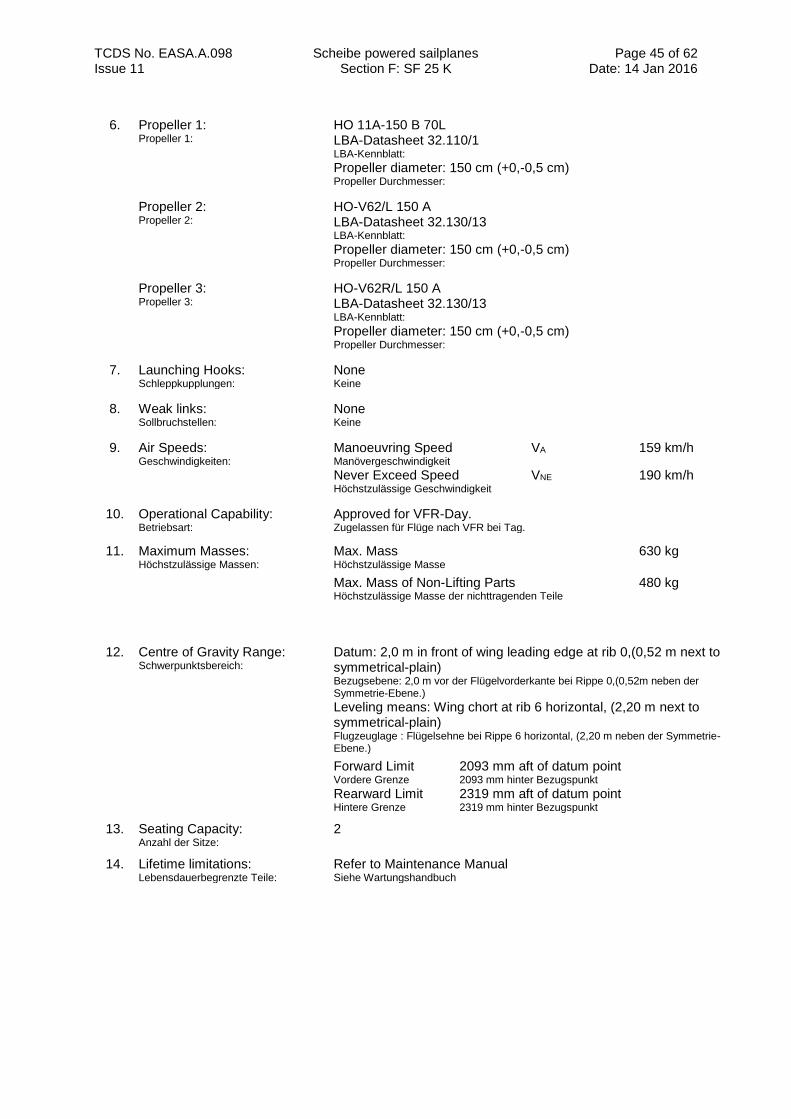
TCDS No. EASA.A.098 Scheibe powered sailplanes Section F: SF 25 K
Page 45 of 62 Date: 14 Jan 2016 Issue 11
6. Propeller 1: Propeller 1:
HO 11A-150 B 70L LBA-Datasheet 32.110/1 LBA-Kennblatt: Propeller diameter: 150 cm (+0,-0,5 cm) Propeller Durchmesser:
Propeller 2: Propeller 2:
HO-V62/L 150 A LBA-Datasheet 32.130/13 LBA-Kennblatt: Propeller diameter: 150 cm (+0,-0,5 cm) Propeller Durchmesser:
Propeller 3: Propeller 3:
HO-V62R/L 150 A LBA-Datasheet 32.130/13 LBA-Kennblatt: Propeller diameter: 150 cm (+0,-0,5 cm) Propeller Durchmesser:
7. Launching Hooks: Schleppkupplungen:
None Keine
8. Weak links: Sollbruchstellen:
None Keine
9. Air Speeds: Geschwindigkeiten:
Manoeuvring Speed VA 159 km/h Manövergeschwindigkeit Never Exceed Speed VNE 190 km/h Höchstzulässige Geschwindigkeit
10. Operational Capability: Betriebsart:
Approved for VFR-Day. Zugelassen für Flüge nach VFR bei Tag.
11. Maximum Masses: Höchstzulässige Massen:
Max. Mass 630 kg Höchstzulässige Masse
Max. Mass of Non-Lifting Parts 480 kg
Höchstzulässige Masse der nichttragenden Teile
12. Centre of Gravity Range: Schwerpunktsbereich:
Datum: 2,0 m in front of wing leading edge at rib 0,(0,52 m next to symmetrical-plain) Bezugsebene: 2,0 m vor der Flügelvorderkante bei Rippe 0,(0,52m neben der Symmetrie-Ebene.)
Leveling means: Wing chort at rib 6 horizontal, (2,20 m next to symmetrical-plain) Flugzeuglage : Flügelsehne bei Rippe 6 horizontal, (2,20 m neben der Symmetrie-Ebene.)
Forward Limit 2093 mm aft of datum point Vordere Grenze 2093 mm hinter Bezugspunkt Rearward Limit 2319 mm aft of datum point Hintere Grenze 2319 mm hinter Bezugspunkt
13. Seating Capacity: Anzahl der Sitze:
2
14. Lifetime limitations: Lebensdauerbegrenzte Teile:
Refer to Maintenance Manual Siehe Wartungshandbuch
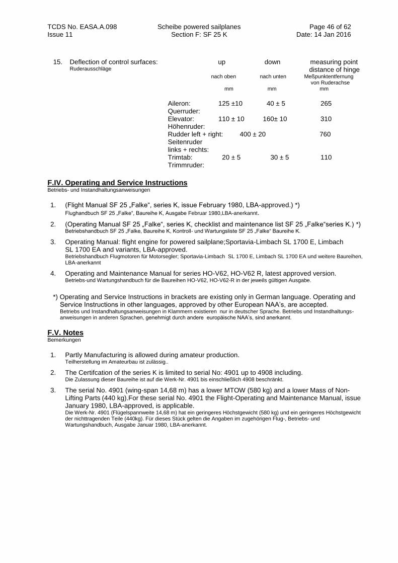
TCDS No. EASA.A.098 Scheibe powered sailplanes Section F: SF 25 K
Page 46 of 62 Date: 14 Jan 2016 Issue 11
15. Deflection of control surfaces: Ruderausschläge
up down measuring point distance of hinge nach oben nach unten Meßpunktentfernung von Ruderachse mm mm mm
Aileron: 125 ±10 40 ± 5 265 Querruder: Elevator: 110 ± 10 160± 10 310 Höhenruder: Rudder left + right: 400 ± 20 760 Seitenruder links + rechts: Trimtab: 20 ± 5 30 ± 5 110 Trimmruder:
F.IV. Operating and Service Instructions Betriebs- und Instandhaltungsanweisungen
1. (Flight Manual SF 25 „Falke“, series K, issue February 1980, LBA-approved.) *) Flughandbuch SF 25 „Falke“, Baureihe K, Ausgabe Februar 1980,LBA-anerkannt.
2. (Operating Manual SF 25 „Falke“, series K, checklist and maintenance list SF 25 „Falke“series K.) *) Betriebshandbuch SF 25 „Falke, Baureihe K, Kontroll- und Wartungsliste SF 25 „Falke“ Baureihe K.
3. Operating Manual: flight engine for powered sailplane;Sportavia-Limbach SL 1700 E, Limbach SL 1700 EA and variants, LBA-approved. Betriebshandbuch Flugmotoren für Motorsegler; Sportavia-Limbach SL 1700 E, Limbach SL 1700 EA und weitere Baureihen, LBA-anerkannt
4. Operating and Maintenance Manual for series HO-V62, HO-V62 R, latest approved version. Betriebs-und Wartungshandbuch für die Baureihen HO-V62, HO-V62-R in der jeweils gültigen Ausgabe.
*) Operating and Service Instructions in brackets are existing only in German language. Operating and
Service Instructions in other languages, approved by other European NAA’s, are accepted. Betriebs und Instandhaltungsanweisungen in Klammern existieren nur in deutscher Sprache. Betriebs und Instandhaltungs- anweisungen in anderen Sprachen, genehmigt durch andere europäische NAA’s, sind anerkannt.
F.V. Notes Bemerkungen
1. Partly Manufacturing is allowed during amateur production. Teilherstellung im Amateurbau ist zulässig..
2. The Certifcation of the series K is limited to serial No: 4901 up to 4908 including. Die Zulassung dieser Baureihe ist auf die Werk-Nr. 4901 bis einschließlich 4908 beschränkt.
3. The serial No. 4901 (wing-span 14,68 m) has a lower MTOW (580 kg) and a lower Mass of Non-Lifting Parts (440 kg).For these serial No. 4901 the Flight-Operating and Maintenance Manual, issue January 1980, LBA-approved, is applicable. Die Werk-Nr. 4901 (Flügelspannweite 14,68 m) hat ein geringeres Höchstgewicht (580 kg) und ein geringeres Höchstgewicht der nichttragenden Teile (440kg). Für dieses Stück gelten die Angaben im zugehörigen Flug-, Betriebs- und Wartungshandbuch, Ausgabe Januar 1980, LBA-anerkannt.
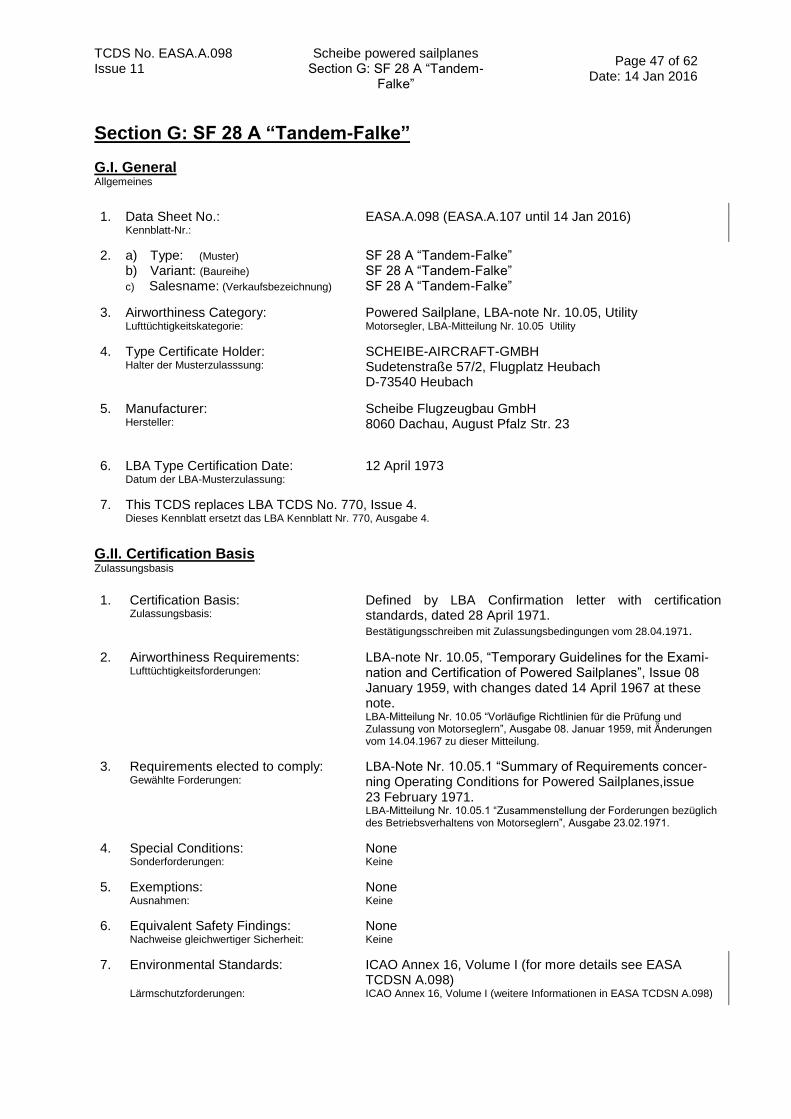
TCDS No. EASA.A.098 Scheibe powered sailplanes Section G: SF 28 A “Tandem-
Falke”
Page 47 of 62 Date: 14 Jan 2016
Issue 11
Section G: SF 28 A “Tandem-Falke”
G.I. General Allgemeines
1. Data Sheet No.: Kennblatt-Nr.:
EASA.A.098 (EASA.A.107 until 14 Jan 2016)
2. a) Type: (Muster) b) Variant: (Baureihe)
c) Salesname: (Verkaufsbezeichnung)
SF 28 A “Tandem-Falke” SF 28 A “Tandem-Falke” SF 28 A “Tandem-Falke”
3. Airworthiness Category: Lufttüchtigkeitskategorie:
Powered Sailplane, LBA-note Nr. 10.05, Utility Motorsegler, LBA-Mitteilung Nr. 10.05 Utility
4. Type Certificate Holder: Halter der Musterzulasssung:
SCHEIBE-AIRCRAFT-GMBH Sudetenstraße 57/2, Flugplatz Heubach D-73540 Heubach
5. Manufacturer: Hersteller:
Scheibe Flugzeugbau GmbH 8060 Dachau, August Pfalz Str. 23
6. LBA Type Certification Date: Datum der LBA-Musterzulassung:
12 April 1973
7. This TCDS replaces LBA TCDS No. 770, Issue 4. Dieses Kennblatt ersetzt das LBA Kennblatt Nr. 770, Ausgabe 4.
G.II. Certification Basis Zulassungsbasis
1. Certification Basis: Zulassungsbasis:
Defined by LBA Confirmation letter with certification standards, dated 28 April 1971. Bestätigungsschreiben mit Zulassungsbedingungen vom 28.04.1971.
2. Airworthiness Requirements: Lufttüchtigkeitsforderungen:
LBA-note Nr. 10.05, “Temporary Guidelines for the Exami- nation and Certification of Powered Sailplanes”, Issue 08 January 1959, with changes dated 14 April 1967 at these note. LBA-Mitteilung Nr. 10.05 “Vorläufige Richtlinien für die Prüfung und Zulassung von Motorseglern”, Ausgabe 08. Januar 1959, mit Änderungen vom 14.04.1967 zu dieser Mitteilung.
3. Requirements elected to comply: Gewählte Forderungen:
LBA-Note Nr. 10.05.1 “Summary of Requirements concer- ning Operating Conditions for Powered Sailplanes,issue 23 February 1971. LBA-Mitteilung Nr. 10.05.1 “Zusammenstellung der Forderungen bezüglich des Betriebsverhaltens von Motorseglern”, Ausgabe 23.02.1971.
4. Special Conditions: Sonderforderungen:
None Keine
5. Exemptions: Ausnahmen:
None Keine
6. Equivalent Safety Findings: Nachweise gleichwertiger Sicherheit:
None Keine
7. Environmental Standards: Lärmschutzforderungen:
ICAO Annex 16, Volume I (for more details see EASA TCDSN A.098) ICAO Annex 16, Volume I (weitere Informationen in EASA TCDSN A.098)
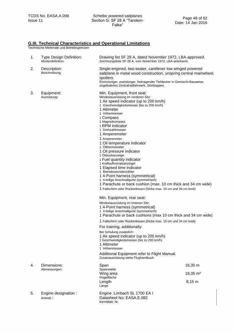
TCDS No. EASA.A.098 Scheibe powered sailplanes Section G: SF 28 A “Tandem-
Falke”
Page 48 of 62 Date: 14 Jan 2016
Issue 11
G.III. Technical Characteristics and Operational Limitations Technische Merkmale und Betriebsgrenzen
1. Type Design Definition: Musterdefinition:
Drawing list SF 28 A, dated November 1972, LBA-approved. Zeichnungsliste SF 28 A, vom November 1972, LBA-anerkannt.
2. Description: Beschreibung:
Single-engined, two-seater, cantilever low winged powered sailplane in metal wood construction, unspring central mainwheel, spoilers. Einmotoriger, zweisitziger, freitragender Tiefdecker in Gemischt-Bauweise, ungefedertes Zentralradfahrwerk, Störklappen.
3. Equipment: Ausrüstung:
Min. Equipment, front seat: Mindestausrüstung im vorderen Sitz:
1 Air speed indicator (up to 200 km/h) 1 Geschwindigkeitsmesser (bis zu 200 km/h)
1 Altimeter 1 Höhenmesser
1 Compass
1 Magnetkompass
1 RPM indicator 1 Drehzahlmesser
1 Amperemeter 1 Amperemeter
1 Oil temperature indicator 1 Ölthermometer
1 Oil pressure indicator 1 Öldruckanzeige
1 Fuel quantity indicator
1 Kraftsoffvorratsanzeiger
1 Elapsed time indicator 1 Betriebsstundenzähler
1 4-Point harness (symmetrical) 1 4-teilige Anschnallgurte (symmetrisch)
1 Parachute or back cushion (max. 10 cm thick and 34 cm wide) 1 Fallschirm oder Rückenkissen (Dicke max. 10 cm und 34 cm breit)
Min. Equipment, rear seat:
Mindestausrüstung im hinteren Sitz:
1 4-Point harness (symmetrical) 1 4-teilige Anschnallgurte (symmetrisch)
1 Parachute or back cushions (max 10 cm thick and 34 cm wide)
1 Fallschirm oder Rückenkissen.(Dicke max. 10 cm und 34 cm breit)
For training, additionally:
Bei Schulung zusätzlich:
1 Air speed indicator (up to 200 km/h) 1 Geschwindigkeitsmesser (bis zu 200 km/h)
1 Altimeter 1 Höhenmesser
Additional Equipment refer to Flight Manual. Zusatzausrüstung siehe Flughandbuch.
4. Dimensions: Abmessungen:
Span 16,30 m Spannweite
Wing area 18,35 m² Flügelfläche
Length 8,15 m Länge
5. Engine designation : Antrieb :
Engine :Limbach SL 1700 EA I Datasheet No: EASA.E.082 Kennblatt: Nr.
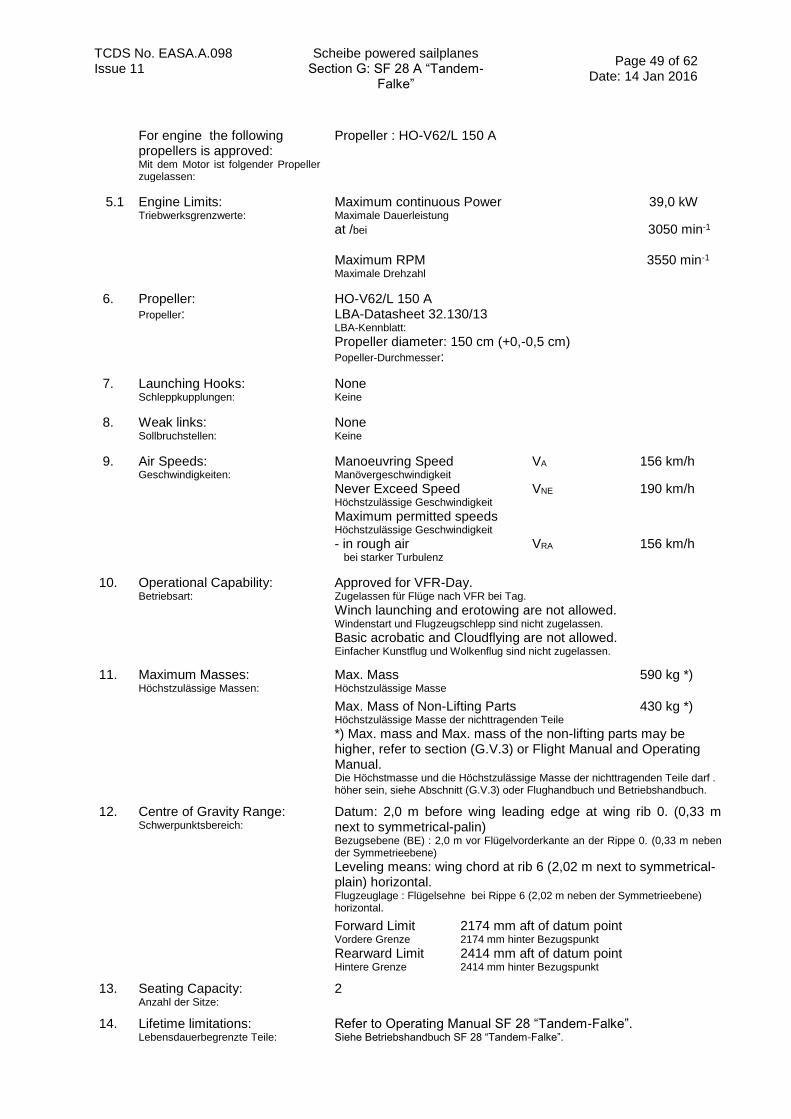
TCDS No. EASA.A.098 Scheibe powered sailplanes Section G: SF 28 A “Tandem-
Falke”
Page 49 of 62 Date: 14 Jan 2016
Issue 11
For engine the following propellers is approved: Mit dem Motor ist folgender Propeller zugelassen:
Propeller : HO-V62/L 150 A
5.1 Engine Limits: Triebwerksgrenzwerte:
Maximum continuous Power 39,0 kW Maximale Dauerleistung
at /bei 3050 min-1
Maximum RPM 3550 min-1
Maximale Drehzahl
6. Propeller: Propeller:
HO-V62/L 150 A LBA-Datasheet 32.130/13 LBA-Kennblatt: Propeller diameter: 150 cm (+0,-0,5 cm) Popeller-Durchmesser:
7. Launching Hooks: Schleppkupplungen:
None Keine
8. Weak links: Sollbruchstellen:
None Keine
9. Air Speeds: Geschwindigkeiten:
Manoeuvring Speed VA 156 km/h Manövergeschwindigkeit Never Exceed Speed VNE 190 km/h Höchstzulässige Geschwindigkeit
Maximum permitted speeds Höchstzulässige Geschwindigkeit - in rough air VRA 156 km/h bei starker Turbulenz
10. Operational Capability: Betriebsart:
Approved for VFR-Day. Zugelassen für Flüge nach VFR bei Tag.
Winch launching and erotowing are not allowed. Windenstart und Flugzeugschlepp sind nicht zugelassen.
Basic acrobatic and Cloudflying are not allowed. Einfacher Kunstflug und Wolkenflug sind nicht zugelassen.
11. Maximum Masses: Höchstzulässige Massen:
Max. Mass 590 kg *) Höchstzulässige Masse
Max. Mass of Non-Lifting Parts 430 kg *)
Höchstzulässige Masse der nichttragenden Teile
*) Max. mass and Max. mass of the non-lifting parts may be higher, refer to section (G.V.3) or Flight Manual and Operating Manual. Die Höchstmasse und die Höchstzulässige Masse der nichttragenden Teile darf . höher sein, siehe Abschnitt (G.V.3) oder Flughandbuch und Betriebshandbuch.
12. Centre of Gravity Range: Schwerpunktsbereich:
Datum: 2,0 m before wing leading edge at wing rib 0. (0,33 m next to symmetrical-palin) Bezugsebene (BE) : 2,0 m vor Flügelvorderkante an der Rippe 0. (0,33 m neben der Symmetrieebene) Leveling means: wing chord at rib 6 (2,02 m next to symmetrical-plain) horizontal. Flugzeuglage : Flügelsehne bei Rippe 6 (2,02 m neben der Symmetrieebene) horizontal.
Forward Limit 2174 mm aft of datum point Vordere Grenze 2174 mm hinter Bezugspunkt Rearward Limit 2414 mm aft of datum point Hintere Grenze 2414 mm hinter Bezugspunkt
13. Seating Capacity: Anzahl der Sitze:
2
14. Lifetime limitations: Lebensdauerbegrenzte Teile:
Refer to Operating Manual SF 28 “Tandem-Falke”. Siehe Betriebshandbuch SF 28 “Tandem-Falke”.
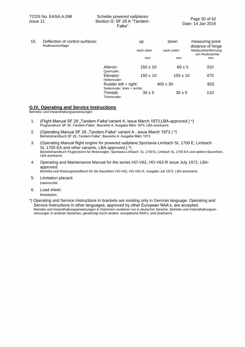
TCDS No. EASA.A.098 Scheibe powered sailplanes Section G: SF 28 A “Tandem-
Falke”
Page 50 of 62 Date: 14 Jan 2016
Issue 11
15. Deflection of control surfaces: Ruderausschläge:
up down measuring point distance of hinge nach oben nach unten Meßpunktentfernung von Ruderachse mm mm mm
Aileron: 150 ± 10 60 ± 5 310 Querruder:
Elevator: 150 ± 10 150 ± 10 470 Höhenruder:
Rudder left + right: 400 ± 30 820 Seitenruder links + rechts:
Trimtab: 30 ± 5 30 ± 5 110 Trimmruder:
G.IV. Operating and Service Instructions Betriebs- und Instandhaltungsanweisungen
1. (Flight Manual SF 28 „Tandem-Falke“variant A, issue March 1973,LBA-approved.) *) Flughandbuch SF 28 „Tandem-Falke“, Baureihe A, Ausgabe März 1973, LBA-anerkannt.
2. (Operating Manual SF 28 „Tandem-Falke“ variant A , issue March 1973.) *) Betriebshandbuch SF 28 „Tandem-Falke“, Baureihe A, Ausgabe März 1973.
3. (Operating Manual flight engine for powered sailplane;Sportavia-Limbach SL 1700 E, Limbach SL 1700 EA and other variants, LBA-approved.) *) Betriebshandbuch Flugmotoren für Motorsegler; Sportavia-Limbach SL 1700 E, Limbach SL 1700 EA und weitere Baureihen, LBA-anerkannt.
4. Operating and Maintenance Manual for the series HO-V62, HO-V62-R issue July 1972, LBA-approved. Betriebs-und Wartungshandbuch für die Baureihen HO-V62, HO-V62-R, Ausgabe Juli 1972, LBA-anerkannt.
5. Limitation placard. Datenschild.
6. Load sheet. Beladeplan.
*) Operating and Service Instructions in brackets are existing only in German language. Operating and Service Instructions in other languages, approved by other European NAA’s, are accepted. Betriebs und Instandhaltungsanweisungen in Klammern existieren nur in deutscher Sprache. Betriebs und Instandhaltungsan- weisungen in anderen Sprachen, genehmigt durch andere europäische NAA’s, sind anerkannt.
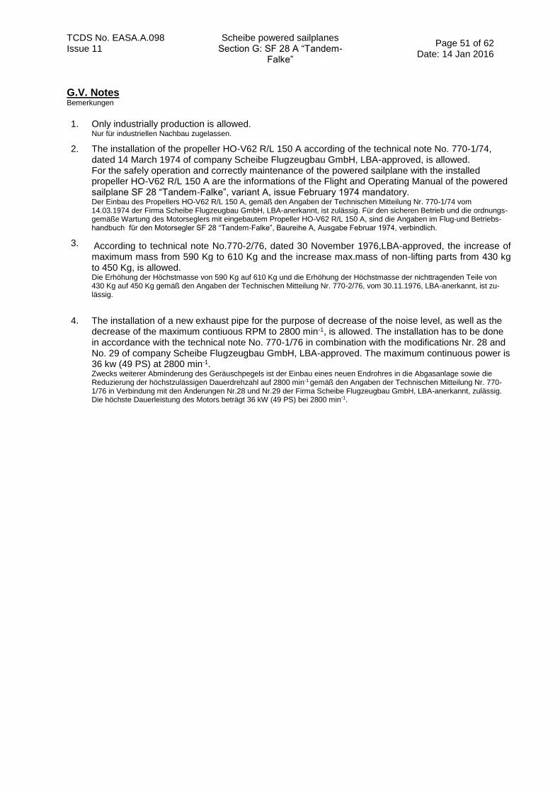
TCDS No. EASA.A.098 Scheibe powered sailplanes Section G: SF 28 A “Tandem-
Falke”
Page 51 of 62 Date: 14 Jan 2016
Issue 11
G.V. Notes Bemerkungen
1. Only industrially production is allowed. Nur für industriellen Nachbau zugelassen.
2. The installation of the propeller HO-V62 R/L 150 A according of the technical note No. 770-1/74, dated 14 March 1974 of company Scheibe Flugzeugbau GmbH, LBA-approved, is allowed. For the safely operation and correctly maintenance of the powered sailplane with the installed propeller HO-V62 R/L 150 A are the informations of the Flight and Operating Manual of the powered sailplane SF 28 “Tandem-Falke”, variant A, issue February 1974 mandatory. Der Einbau des Propellers HO-V62 R/L 150 A, gemäß den Angaben der Technischen Mitteilung Nr. 770-1/74 vom 14.03.1974 der Firma Scheibe Flugzeugbau GmbH, LBA-anerkannt, ist zulässig. Für den sicheren Betrieb und die ordnungs- gemäße Wartung des Motorseglers mit eingebautem Propeller HO-V62 R/L 150 A, sind die Angaben im Flug-und Betriebs- handbuch für den Motorsegler SF 28 “Tandem-Falke”, Baureihe A, Ausgabe Februar 1974, verbindlich.
3. According to technical note No.770-2/76, dated 30 November 1976,LBA-approved, the increase of maximum mass from 590 Kg to 610 Kg and the increase max.mass of non-lifting parts from 430 kg to 450 Kg, is allowed. Die Erhöhung der Höchstmasse von 590 Kg auf 610 Kg und die Erhöhung der Höchstmasse der nichttragenden Teile von 430 Kg auf 450 Kg gemäß den Angaben der Technischen Mitteilung Nr. 770-2/76, vom 30.11.1976, LBA-anerkannt, ist zu- lässig.
4. The installation of a new exhaust pipe for the purpose of decrease of the noise level, as well as the decrease of the maximum contiuous RPM to 2800 min-1, is allowed. The installation has to be done in accordance with the technical note No. 770-1/76 in combination with the modifications Nr. 28 and No. 29 of company Scheibe Flugzeugbau GmbH, LBA-approved. The maximum continuous power is 36 kw (49 PS) at 2800 min-1. Zwecks weiterer Abminderung des Geräuschpegels ist der Einbau eines neuen Endrohres in die Abgasanlage sowie die Reduzierung der höchstzulässigen Dauerdrehzahl auf 2800 min-1 gemäß den Angaben der Technischen Mitteilung Nr. 770-1/76 in Verbindung mit den Änderungen Nr.28 und Nr.29 der Firma Scheibe Flugzeugbau GmbH, LBA-anerkannt, zulässig. Die höchste Dauerleistung des Motors beträgt 36 kW (49 PS) bei 2800 min-1.

TCDS No. EASA.A.098 Scheibe powered sailplanes SECTION H: SF 36 A
Page 52 of 62 Date: 14 Jan 2016 Issue 11
SECTION H: SF 36 A
H.I. General Allgemeines
1. Data Sheet No.: Kennblatt Nr.:
EASA.A.098 (EASA.A.578 until 14 Jan 2016)
2. a) Type: (Muster) b) Variant: (Baureihe)
SF 36 SF 36 A
3. Airworthiness Category: Lufttüchtigkeitskategorie :
Powered Sailplane, CS-22 - Utility, self-launching Motorsegler, CS-22 - Utility, eigenstartfähig
4. Manufacturer: Hersteller
Scheibe-Flugzeugbau GmbH August-Pfalz-Straße 23 D-85221 Dachau Deutschland
H.II. Certification Basis Zulassungsbasis
1. Certification Basis: Zulassungsbasis:
Defined by LBA-Letter I 31-819/79 Definiert mit LBA-Brief I 31-819/79
2. Airworthiness Requirements: Lufttüchtigkeitsforderungen:
JAR 22 for Sailplanes and Powered Sailplanes, including Change 4, dated 1989 Lufttüchtigkeitsforderungen für Segelflugzeuge und Motorsegler (JAR 22), einschließlich Change 4, Ausgabe 1989
3. Requirements elected to comply: Gewählte Forderungen
Preliminary Standards for Structural Substantiation of Sailplane Components consisting of Glass Fibre Reinforced Plastics, issued March 1965 Vorläufige Richtlinien zur Führung des Festigkeitsnachweises für Bauteile aus glasfaserverstärkten Kunststoffen von Segelflugzeugen, Ausgabe März 1965.
Guideline for the analysis of the electrical system for powered sailplanes, I334-MS 90, issued 22. November 1990. Richtlinie für den Nachweis der elektrischen Anlage in Motorseglern, I334-MS 90 vom 22. November 1990.
4. Special Conditions: Sonderforderungen:
None
5. Exemptions: Ausnahmen:
None
6. Equivalent Safety Findings: Nachweise gleichwertiger Sicherheit:
JAR 22.777 d)
7. Environmental Standards: Lärmschutzforderungen:
ICAO Annex 16, Volume I (for more details see EASA TCDSN A.098) ICAO Annex 16, Volume I (weitere Informationen in EASA TCDSN A.098)
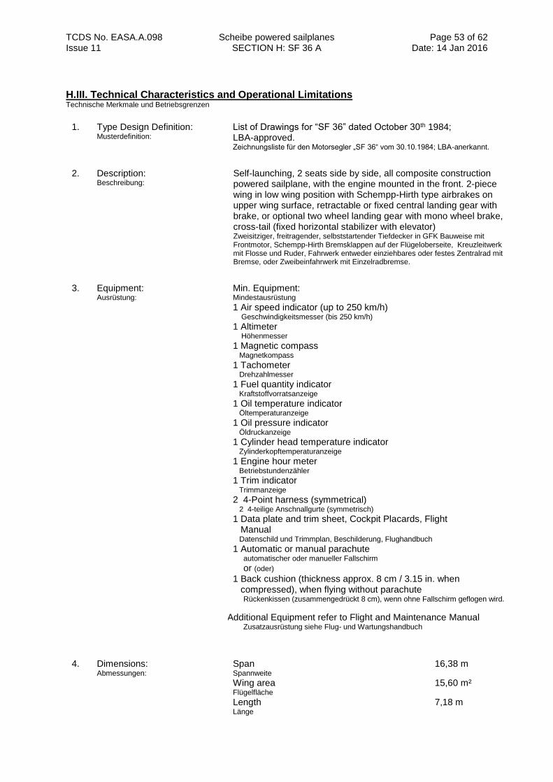
TCDS No. EASA.A.098 Scheibe powered sailplanes SECTION H: SF 36 A
Page 53 of 62 Date: 14 Jan 2016 Issue 11
H.III. Technical Characteristics and Operational Limitations Technische Merkmale und Betriebsgrenzen
1. Type Design Definition: Musterdefinition:
List of Drawings for “SF 36” dated October 30th 1984; LBA-approved. Zeichnungsliste für den Motorsegler „SF 36“ vom 30.10.1984; LBA-anerkannt.
2. Description: Beschreibung:
Self-launching, 2 seats side by side, all composite construction powered sailplane, with the engine mounted in the front. 2-piece wing in low wing position with Schempp-Hirth type airbrakes on upper wing surface, retractable or fixed central landing gear with brake, or optional two wheel landing gear with mono wheel brake, cross-tail (fixed horizontal stabilizer with elevator) Zweisitziger, freitragender, selbststartender Tiefdecker in GFK Bauweise mit Frontmotor, Schempp-Hirth Bremsklappen auf der Flügeloberseite, Kreuzleitwerk mit Flosse und Ruder, Fahrwerk entweder einziehbares oder festes Zentralrad mit Bremse, oder Zweibeinfahrwerk mit Einzelradbremse.
3. Equipment: Ausrüstung:
Min. Equipment: Mindestausrüstung
1 Air speed indicator (up to 250 km/h) Geschwindigkeitsmesser (bis 250 km/h)
1 Altimeter Höhenmesser
1 Magnetic compass Magnetkompass
1 Tachometer Drehzahlmesser
1 Fuel quantity indicator Kraftstoffvorratsanzeige
1 Oil temperature indicator Öltemperaturanzeige
1 Oil pressure indicator Öldruckanzeige
1 Cylinder head temperature indicator Zylinderkopftemperaturanzeige
1 Engine hour meter Betriebstundenzähler
1 Trim indicator Trimmanzeige
2 4-Point harness (symmetrical) 2 4-teilige Anschnallgurte (symmetrisch)
1 Data plate and trim sheet, Cockpit Placards, Flight Manual Datenschild und Trimmplan, Beschilderung, Flughandbuch
1 Automatic or manual parachute automatischer oder manueller Fallschirm
or (oder)
1 Back cushion (thickness approx. 8 cm / 3.15 in. when compressed), when flying without parachute
Rückenkissen (zusammengedrückt 8 cm), wenn ohne Fallschirm geflogen wird.
AAdditional Equipment refer to Flight and Maintenance Manual Zusatzausrüstung siehe Flug- und Wartungshandbuch
4. Dimensions: Abmessungen:
Span 16,38 m Spannweite
Wing area 15,60 m² Flügelfläche
Length 7,18 m Länge

TCDS No. EASA.A.098 Scheibe powered sailplanes SECTION H: SF 36 A
Page 54 of 62 Date: 14 Jan 2016 Issue 11
5. Engine designation: Antrieb
Engine 2 Antrieb 2
Engine 3 Antrieb 3
Engine 4 Antrieb 4
Limbach L 2000 EA 1, TCDS: EASA.E.083 Limbach L 2000 EA 1, EASA-Kennblatt EASA.E.083
Limbach L 2000 EA 1.B, TCDS: EASA.E.083 Limbach L 2000 EA 1.B, EASA-Kennblatt EASA.E.083
Sauer SS 2100 H1S; TCDS: LBA-Kennblatt-Nr. 4608 Sauer SS 2100 H1S; TCDS: LBA-Kennblatt-Nr. 4608
Sauer S 2100-1-SS1; TCDS: LBA-Kennblatt-Nr. 4608 Sauer SS 2100-1-SS1; TCDS: LBA-Kennblatt-Nr. 4608
Remark:
Bemerkung:
Engine 4: New name of engine no. 3 after manufacturing date March 1st 1998, same propeller as for engine 3. Motor 4: Neue Bezeichnung für Motor 3 ab Herstellungsdatum 01.03.1998; gleicher Propeller wie Motor 3.
5.1 Engine Limits: Triebwerksgrenzwerte
Engine 2 Triebwerk 2
Engine 3 Triebwerk 3
Maximum Take-off Power (max. 5 minutes) 59,0 kW Maximale Startleistung (max. 5 min.)
at/bei 3400 rpm Maximum continuous Power 51,0 kW Maximale Dauerleistung
at/bei 2800 rpm Maximum Take-off Power (max. 5 minutes) 59,0 kW Maximale Startleistung (max. 5 min.)
at/bei 3400 rpm Maximum continuous Power 51,0 kW Maximale Dauerleistung
at/bei 2800 rpm Maximum Take-off Power (max. 5 minutes) 59,0 kW Maximale Startleistung (max. 5 min.)
at/bei 3000 rpm Maximum continuous Power 54,0 kW Maximale Dauerleistung
at/bei 2700 rpm
Engine 4 Triebwerk 4
Maximum Take-off Power (max. 5 minutes) 59,0 kW Maximale Startleistung (max. 5 min.)
at/bei 3000 rpm Maximum continuous Power 54,0 kW Maximale Dauerleistung
at/bei 2700 rpm
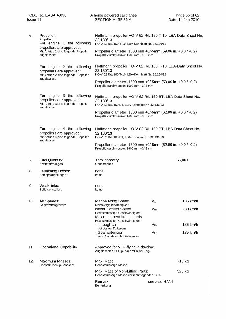
TCDS No. EASA.A.098 Scheibe powered sailplanes SECTION H: SF 36 A
Page 55 of 62 Date: 14 Jan 2016 Issue 11
6. Propeller: Propeller:
For engine 1 the following propellers are approved: Mit Antrieb 1 sind folgende Propeller zugelassen:
For engine 2 the following propellers are approved: Mit Antrieb 2 sind folgende Propeller zugelassen: For engine 3 the following propellers are approved: Mit Antrieb 3 sind folgende Propeller zugelassen
For engine 4 the following propellers are approved: Mit Antrieb 4 sind folgende Propeller zugelassen
Hoffmann propeller HO-V 62 R/L 160 T-10, LBA-Data Sheet No. 32.130/13 HO-V 62 R/L 160 T-10, LBA-Kennblatt Nr. 32.130/13
Propeller diameter: 1500 mm +0/-5mm (59.06 in. +0,0 / -0,2) Propellerdurchmesser: 1500 mm +0/-5 mm
Hoffmann propeller HO-V 62 R/L 160 T-10, LBA-Data Sheet No. 32.130/13 HO-V 62 R/L 160 T-10, LBA-Kennblatt Nr. 32.130/13
Propeller diameter: 1500 mm +0/-5mm (59.06 in. +0,0 / -0,2) Propellerdurchmesser: 1500 mm +0/-5 mm
Hoffmann propeller HO-V 62 R/L 160 BT, LBA-Data Sheet No. 32.130/13 HO-V 62 R/L 160 BT, LBA-Kennblatt Nr. 32.130/13
Propeller diameter: 1600 mm +0/-5mm (62.99 in. +0,0 / -0,2) Propellerdurchmesser: 1600 mm +0/-5 mm
Hoffmann propeller HO-V 62 R/L 160 BT, LBA-Data Sheet No. 32.130/13 HO-V 62 R/L 160 BT, LBA-Kennblatt Nr. 32.130/13
Propeller diameter: 1600 mm +0/-5mm (62.99 in. +0,0 / -0,2) Propellerdurchmesser: 1600 mm +0/-5 mm
7. Fuel Quantity: Kraftstoffmengen
Total capacity 55,00 l Gesamtinhalt
8. Launching Hooks: Schleppkupplungen:
none
keine
9. Weak links: Sollbruchstellen:
none
keine
10. Air Speeds: Geschwindigkeiten:
Manoeuvring Speed VA 185 km/h Manövergeschwindigkeit Never Exceed Speed VNE 230 km/h Höchstzulässige Geschwindigkeit
Maximum permitted speeds Höchstzulässige Geschwindigkeit - in rough air VRA 185 km/h bei starker Turbulenz
- Gear extension VLO 185 km/h zum Ausfahren des Fahrwerks
11. Operational Capability Approved for VFR-flying in daytime. Zugelassen für Flüge nach VFR bei Tag.
12. Maximum Masses: Höchstzulässige Massen:
Max. Mass: Höchstzulässige Masse
715 kg
Max. Mass of Non-Lifting Parts: Höchstzulässige Masse der nichttragenden Teile
525 kg
Remark: see also H.V.4 Bemerkung:
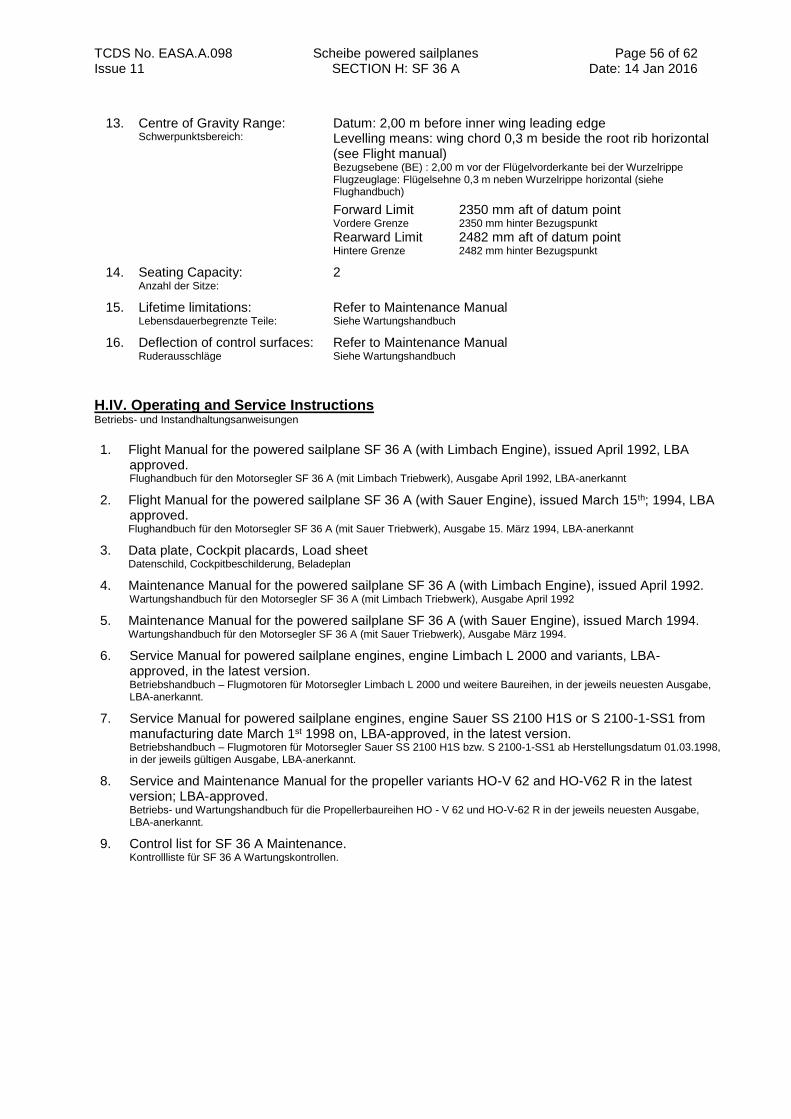
TCDS No. EASA.A.098 Scheibe powered sailplanes SECTION H: SF 36 A
Page 56 of 62 Date: 14 Jan 2016 Issue 11
13. Centre of Gravity Range: Schwerpunktsbereich:
Datum: 2,00 m before inner wing leading edge Levelling means: wing chord 0,3 m beside the root rib horizontal (see Flight manual) Bezugsebene (BE) : 2,00 m vor der Flügelvorderkante bei der Wurzelrippe Flugzeuglage: Flügelsehne 0,3 m neben Wurzelrippe horizontal (siehe Flughandbuch)
Forward Limit 2350 mm aft of datum point Vordere Grenze 2350 mm hinter Bezugspunkt Rearward Limit 2482 mm aft of datum point Hintere Grenze 2482 mm hinter Bezugspunkt
14. Seating Capacity: Anzahl der Sitze:
2
15. Lifetime limitations: Lebensdauerbegrenzte Teile:
Refer to Maintenance Manual Siehe Wartungshandbuch
16. Deflection of control surfaces: Ruderausschläge
Refer to Maintenance Manual Siehe Wartungshandbuch
H.IV. Operating and Service Instructions Betriebs- und Instandhaltungsanweisungen
1. Flight Manual for the powered sailplane SF 36 A (with Limbach Engine), issued April 1992, LBA approved. Flughandbuch für den Motorsegler SF 36 A (mit Limbach Triebwerk), Ausgabe April 1992, LBA-anerkannt
2. Flight Manual for the powered sailplane SF 36 A (with Sauer Engine), issued March 15th; 1994, LBA approved. Flughandbuch für den Motorsegler SF 36 A (mit Sauer Triebwerk), Ausgabe 15. März 1994, LBA-anerkannt
3. Data plate, Cockpit placards, Load sheet Datenschild, Cockpitbeschilderung, Beladeplan
4. Maintenance Manual for the powered sailplane SF 36 A (with Limbach Engine), issued April 1992. Wartungshandbuch für den Motorsegler SF 36 A (mit Limbach Triebwerk), Ausgabe April 1992
5. Maintenance Manual for the powered sailplane SF 36 A (with Sauer Engine), issued March 1994. Wartungshandbuch für den Motorsegler SF 36 A (mit Sauer Triebwerk), Ausgabe März 1994.
6. Service Manual for powered sailplane engines, engine Limbach L 2000 and variants, LBA- approved, in the latest version. Betriebshandbuch – Flugmotoren für Motorsegler Limbach L 2000 und weitere Baureihen, in der jeweils neuesten Ausgabe, LBA-anerkannt.
7. Service Manual for powered sailplane engines, engine Sauer SS 2100 H1S or S 2100-1-SS1 from manufacturing date March 1st 1998 on, LBA-approved, in the latest version. Betriebshandbuch – Flugmotoren für Motorsegler Sauer SS 2100 H1S bzw. S 2100-1-SS1 ab Herstellungsdatum 01.03.1998, in der jeweils gültigen Ausgabe, LBA-anerkannt.
8. Service and Maintenance Manual for the propeller variants HO-V 62 and HO-V62 R in the latest version; LBA-approved. Betriebs- und Wartungshandbuch für die Propellerbaureihen HO - V 62 und HO-V-62 R in der jeweils neuesten Ausgabe, LBA-anerkannt.
9. Control list for SF 36 A Maintenance. Kontrollliste für SF 36 A Wartungskontrollen.
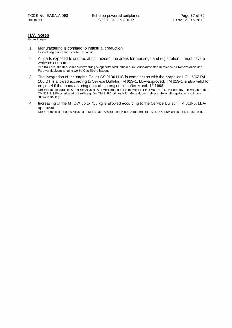
TCDS No. EASA.A.098 Scheibe powered sailplanes SECTION I: SF 36 R
Page 57 of 62 Date: 14 Jan 2016 Issue 11
H.V. Notes Bemerkungen
1. Manufacturing is confined to industrial production. Herstellung nur im Industriebau zulässig.
2. All parts exposed to sun radiation – except the areas for markings and registration – must have a white colour surface. Alle Bauteile, die der Sonneneinstrahlung ausgesetzt sind, müssen, mit Ausnahme des Bereiches für Kennzeichen und Farbwarnlackierung, eine weiße Oberfläche haben.
3. The integration of the engine Sauer SS 2100 H1S in combination with the propeller HO – V62 R/L 160 BT is allowed according to Service Bulletin TM 819-1, LBA-approved. TM 819-1 is also valid for engine 4 if the manufacturing date of the engine lies after March 1st 1998. Der Einbau des Motors Sauer SS 2100 H1S in Verbindung mit dem Propeller HO-V62R/L 160 BT gemäß den Angaben der TM 819-1, LBA-anerkannt, ist zulässig. Die TM 819-1 gilt auch für Motor 4, wenn dessen Herstellungsdatum nach dem 01.03.1998 liegt.
4. Increasing of the MTOW up to 725 kg is allowed according to the Service Bulletin TM 819-5, LBA-approved. Die Erhöhung der höchstzulässigen Masse auf 725 kg gemäß den Angaben der TM 819-5, LBA-anerkannt, ist zulässig.
TCDS No. EASA.A.098 Scheibe powered sailplanes SECTION I: SF 36 R
Page 58 of 62 Date: 14 Jan 2016 Issue 11
SECTION I: SF 36 R
I.I. General Allgemeines
1. Data Sheet No.: Kennblatt Nr.:
EASA.A.098 (EASA.A.578 until 14 Jan 2016)
2. a) Type: (Muster) b) Variant: (Baureihe)
SF 36 SF 36 R
3. Airworthiness Category: Lufttüchtigkeitskategorie :
Powered Sailplane, CS-22 - Utility, self-launching Motorsegler, CS-22 - Utility, eigenstartfähig
4. Manufacturer: Hersteller
Scheibe-Flugzeugbau GmbH August-Pfalz-Straße 23 85221 Dachau Deutschland
I.II. Certification Basis Zulassungsbasis
1. Certification Basis: Zulassungsbasis:
Defined by LBA-Letter I 31-819/79 and amended with letter I 412-819/94 Definiert mit LBA-Brief I 31-819/79 und ergänzt mit Schreiben I 412-819/94
2. Airworthiness Requirements: Lufttüchtigkeitsforderungen:
JAR 22 for Sailplanes and Powered Sailplanes, including Change 4, dated 1989. Lufttüchtigkeitsforderungen für Segelflugzeuge und Motorsegler (JAR 22), einschließlich Change 4, Ausgabe 1989.
3. Requirements elected to comply: Gewählte Forderungen
Standards for the Structural Substantiation of Sailplane and Powered Sailplane Components consisting of Glass- and Carbon Fibre Reinforced Plastics, issued March 1965. Richtlinien zur Führung des Festigkeitsnachweises für Bauteile aus glas- und kohlenfaserverstärkten Kunststoffen von Segelflugzeugen und Motorseglern, Ausgabe März 1965.
Guideline for the analysis of the electrical system for powered sailplanes, I334-MS 90, issued 22. November 1990. Richtlinie für den Nachweis der elektrischen Anlage in Motorseglern, I334-MS 90 vom 22. November 1990.
4. Special Conditions: Sonderforderungen:
None
5. Exemptions: Ausnahmen:
None
6. Equivalent Safety Findings: Nachweise gleichwertiger Sicherheit:
JAR 22.777 d)
7. Environmental Standards: Lärmschutzforderungen:
ICAO Annex 16, Volume I (for more details see EASA TCDSN A.098) ICAO Annex 16, Volume I (weitere Informationen in EASA TCDSN A.098)
TCDS No. EASA.A.098 Scheibe powered sailplanes SECTION I: SF 36 R
Page 59 of 62 Date: 14 Jan 2016 Issue 11
I.III. Technical Characteristics and Operational Limitations Technische Merkmale und Betriebsgrenzen
1.. Type Design Definition: Musterdefinition:
List of Drawings for “SF 36” dated 30.10.1984 with amendments dated March 14th 1994 and July 1st 1994; LBA-approved. Zeichnungsliste für den Motorsegler „SF 36“ vom 30.10.1984 mit Ergänzungen vom 14. März 1994 und 01.Juli 1994; LBA-anerkannt.
2.. Description: Beschreibung:
Self-launching, 2 seats side by side, all composite construction powered sailplane, with the engine mounted in the front. 2-piece wing in low wing position with Schempp-Hirth type airbrakes on upper wing surface, retractable or fixed central landing gear with brake, or optional two wheel landing gear with mono wheel brake, cross-tail (fixed horizontal stabilizer with elevator) Zweisitziger, freitragender, selbststartender Tiefdecker in GFK Bauweise mit Frontmotor, Schempp-Hirth Bremsklappen auf der Flügeloberseite, Kreuzleitwerk mit Flosse und Ruder, Fahrwerk entweder einziehbares oder festes Zentralrad mit Bremse, oder Zweibeinfahrwerk mit Einzelradbremse.
3. Equipment: Ausrüstung:
Min. Equipment: Mindestausrüstung
1 Air speed indicator (up to 250 km/h) Geschwindigkeitsmesser (bis 250 km/h)
1 Altimeter Höhenmesser
1 Magnetic compass Magnetkompass
1 Tachometer Drehzahlmesser
1 Fuel quantity indicator Kraftstoffvorratsanzeige
1 Oil temperature indicator Öltemperaturanzeige
1 Oil pressure indicator Öldruckanzeige
1 Cylinder head temperature indicator Zylinderkopftemperaturanzeige
1 Engine hour meter Betriebstundenzähler
1 Trim indicator Trimmanzeige
2 4-Point harness (symmetrical) 2 4-teilige Anschnallgurte (symmetrisch)
1 Data plate and trim sheet, Cockpit Placards, Flight Manual Datenschild und Trimmplan, Beschilderung, Flughandbuch
1 Automatic or manual parachute automatischer oder manueller Fallschirm
or (oder)
1 Back cushion (thickness approx. 8 cm / 3.15 in. when compressed), when flying without parachute
Rückenkissen (zusammengedrückt 8 cm), wenn ohne Fallschirm geflogen wird.
AAdditional Equipment refer to Flight and Maintenance Manual Zusatzausrüstung siehe Flug- und Wartungshandbuch
4. Dimensions: Abmessungen:
Span 16,38 m Spannweite
Wing area 15,60 m² Flügelfläche
Length 7,18 m Länge
TCDS No. EASA.A.098 Scheibe powered sailplanes SECTION I: SF 36 R
Page 60 of 62 Date: 14 Jan 2016 Issue 11
5. Engine designation: Antrieb
Engine 2 Antrieb 2
Rotax 912 A2; TCDS: EASA.E.121 Rotax 912 A2; Kennblatt: EASA.E.121
Rotax 912 A3; TCDS: EASA.E.121 Rotax 912 A3; Kennblatt: EASA.E.121
5.1 Engine Limits: Triebwerksgrenzwerte
Engine 2 Triebwerk 2
Maximum Take-off Power (max. 5 minutes) 59,6 kW Maximale Startleistung (max. 5 min.)
at/bei 5800 rpm Maximum continuous Power 58,0 kW Maximale Dauerleistung
at/bei 5500 rpm Maximum Take-off Power (max. 5 minutes) 59,6 kW Maximale Startleistung (max. 5 min.)
at/bei 5800 rpm Maximum continuous Power 58,0 kW Maximale Dauerleistung
at/bei 5500 rpm
6. Propeller: Propeller:
For engine 1 the following propellers are approved: Mit Antrieb 1 sind folgende Propeller zugelassen:
For engine 2 the following propellers are approved: Mit Antrieb 2 sind folgende Propeller zugelassen:
Hoffmann propeller HO-V 62R/ 170 FA, LBA-Data Sheet No. 32.130/13 HO-V 62 R/ 170 FA, LBA-Kennblatt Nr. 32.130/13
Propeller diameter: 1700 mm +0/-5mm (66.93 in. +0,0 / -0,2) Propellerdurchmesser: 1700 mm +0/-5 mm
Hoffmann propeller HO-V 62HS/ 170 FA, LBA-Data Sheet No. 32.130/13 HO-V 62HS/ 170 FA, LBA-Kennblatt Nr. 32.130/13
Propeller diameter: 1700 mm +0/-5mm (66.93 in. +0,0 / -0,2) Propellerdurchmesser: 1700 mm +0/-5 mm
7. Fuel Quantity: Kraftstoffmengen
Total capacity 55,0 l Gesamtinhalt
8. Launching Hooks: Schleppkupplungen:
none
keine
9. Weak links: Sollbruchstellen:
none
keine
10. Air Speeds: Geschwindigkeiten:
Maximum permitted speeds Höchstzulässige Geschwindigkeiten
Manoeuvring Speed VA 185 km/h Manövergeschwindigkeit Never Exceed Speed VNE 230 km/h Höchstzulässige Geschwindigkeit
Maximum permitted speeds Höchstzulässige Geschwindigkeit - in rough air VRA 185 km/h bei starker Turbulenz
- Gear extension VLO 185 km/h zum Ausfahren des Fahrwerks
11. Operational Capability Approved for VFR-flying in daytime. Zugelassen für Flüge nach VFR bei Tag.
TCDS No. EASA.A.098 Scheibe powered sailplanes Administrative section
Page 61 of 62 Date: 14 Jan 2016 Issue 11
12. Maximum Masses: Höchstzulässige Massen:
Max. Mass: Höchstzulässige Masse
715 kg
Max. Mass of Non-Lifting Parts: Höchstzulässige Masse der nichttragenden Teile
Remark: see also I.V.3 Bemerkung:
525 kg
13. Centre of Gravity Range: Schwerpunktsbereich:
Datum: 2,00 m before inner wing leading edge Levelling means: wing chord 0,3 m beside the root rib horizontal (see Flight manual) Bezugsebene (BE) : 2,00 m vor der Flügelvorderkante bei der Wurzelrippe Flugzeuglage: Flügelsehne 0,3 m neben Wurzelrippe horizontal (siehe Flughandbuch)
Forward Limit 2350 mm aft of datum point Vordere Grenze 2350 mm hinter Bezugspunkt Rearward Limit 2482 mm aft of datum point Hintere Grenze 2482 mm hinter Bezugspunkt
14. Seating Capacity: Anzahl der Sitze:
2
15. Lifetime limitations: Lebensdauerbegrenzte Teile:
Refer to Maintenance Manual Siehe Wartungshandbuch
16. Deflection of control surfaces: Ruderausschläge
Refer to Maintenance Manual Siehe Wartungshandbuch
I.IV. Operating and Service Instructions Betriebs- und Instandhaltungsanweisungen
1. Flight Manual for the powered sailplane SF 36 R, issued July 1st 1994, LBA approved. Flughandbuch für den Motorsegler SF 36 R, Ausgabe 1. Juli 1994, LBA-anerkannt.
2. Data sheet, Cockpit placards, Load sheet Datenschild, Cockpitbeschilderung, Beladeplan
3. Maintenance Manual for the powered sailplane SF 36 R, issued July 1st 1994. Wartungshandbuch für den Motorsegler SF 36 R, Ausgabe 1. Juli 1994.
4. Service Manual for Rotax 912 A ( ), in the latest approved version. Betriebshandbuch für Rotax 912 A ( ), in der letztgültigen Ausgabe.
5. Service and Maintenance Manual for the propeller variant HO – V 62 (R/HS) in the latest version; LBA-approved. Betriebs- und Wartungshandbuch für die Propellerbaureihen HO – V 62 (R/HS) in der jeweils neuesten Ausgabe, LBA-anerkannt.
6. Control list for SF 36 R Maintenance. Kontrollliste für SF 36 R Wartungskontrollen.
I.V. Notes Bemerkungen
1. Manufacturing is confined to industrial production. Herstellung nur im Industriebau zulässig.
2. All parts exposed to sun radiation – except the areas for markings and registration – must have a white colour surface. Alle Bauteile, die der Sonneneinstrahlung ausgesetzt sind, müssen, mit Ausnahme des Bereiches für Kennzeichen und Farbwarnlackierung, eine weiße Oberfläche haben.
3. Increasing of the MTOW up to 725 kg is allowed according to the Service Bulletin TM 819-5 Die Erhöhung der höchstzulässigen Masse auf 725 kg gemäß den Angaben der TM 819-5, LBA-anerkannt, ist zulässig.
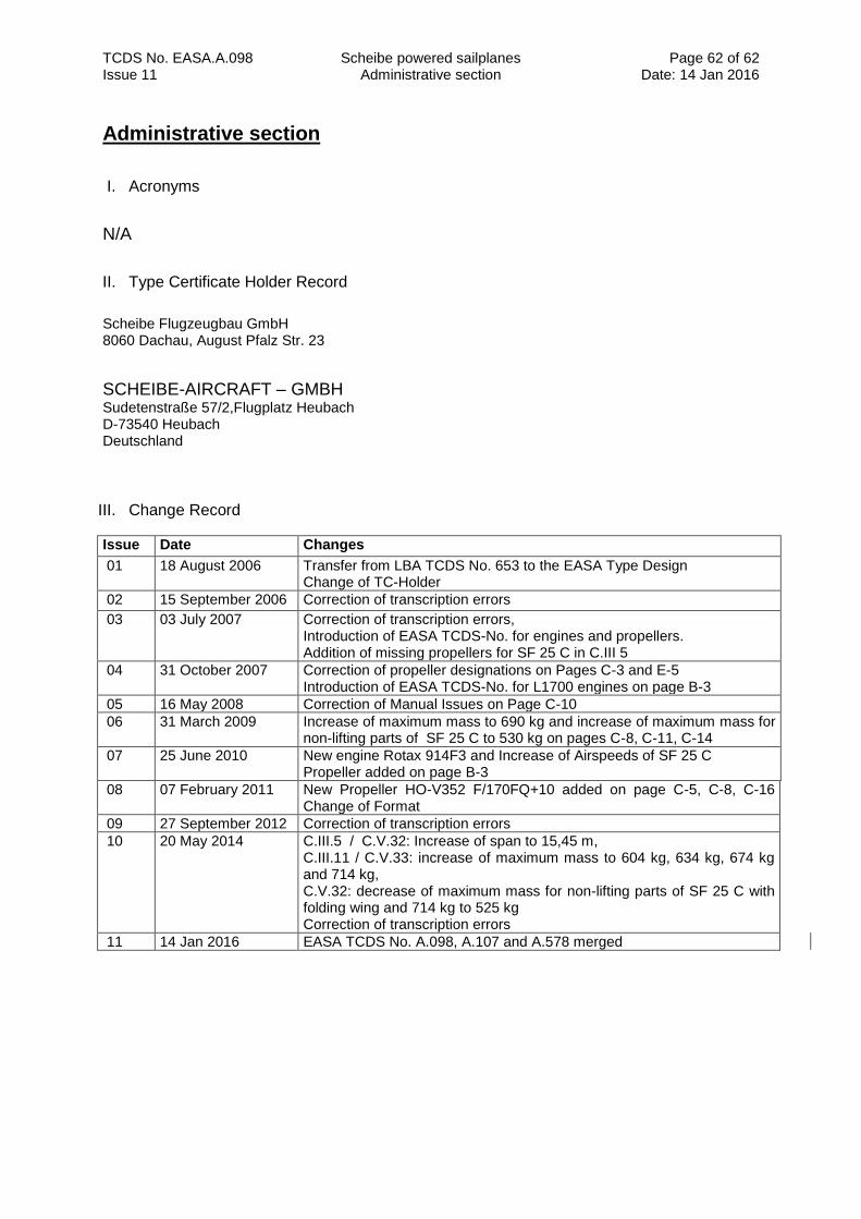
TCDS No. EASA.A.098 Scheibe powered sailplanes Administrative section
Page 62 of 62 Date: 14 Jan 2016 Issue 11
Administrative section
I. Acronyms
N/A
II. Type Certificate Holder Record
Scheibe Flugzeugbau GmbH 8060 Dachau, August Pfalz Str. 23
SCHEIBE-AIRCRAFT – GMBH Sudetenstraße 57/2,Flugplatz Heubach D-73540 Heubach Deutschland
III. Change Record
Issue Date Changes
01 18 August 2006 Transfer from LBA TCDS No. 653 to the EASA Type Design Change of TC-Holder
02 15 September 2006 Correction of transcription errors
03 03 July 2007 Correction of transcription errors, Introduction of EASA TCDS-No. for engines and propellers. Addition of missing propellers for SF 25 C in C.III 5
04 31 October 2007 Correction of propeller designations on Pages C-3 and E-5 Introduction of EASA TCDS-No. for L1700 engines on page B-3
05 16 May 2008 Correction of Manual Issues on Page C-10
06 31 March 2009 Increase of maximum mass to 690 kg and increase of maximum mass for non-lifting parts of SF 25 C to 530 kg on pages C-8, C-11, C-14
07 25 June 2010 New engine Rotax 914F3 and Increase of Airspeeds of SF 25 C Propeller added on page B-3
08
07 February 2011 New Propeller HO-V352 F/170FQ+10 added on page C-5, C-8, C-16 Change of Format
09 27 September 2012 Correction of transcription errors
10 20 May 2014 C.III.5 / C.V.32: Increase of span to 15,45 m, C.III.11 / C.V.33: increase of maximum mass to 604 kg, 634 kg, 674 kg and 714 kg, C.V.32: decrease of maximum mass for non-lifting parts of SF 25 C with folding wing and 714 kg to 525 kg Correction of transcription errors
11 14 Jan 2016 EASA TCDS No. A.098, A.107 and A.578 merged