Embed Size (px)
Citation preview

EARTHMOVING/CONSTRUCTION WHEELS
EARTHMOVING/CONSTRUCTION WHEELS
i
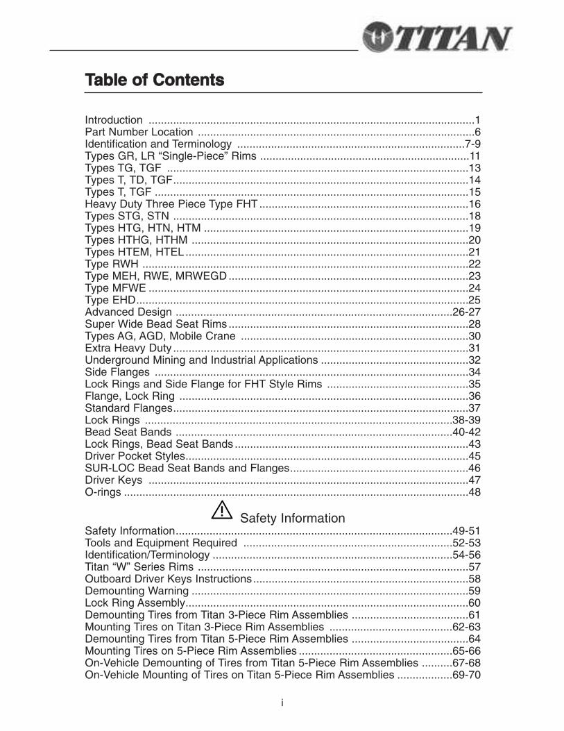
Introduction ..........................................................................................................1Part Number Location ..........................................................................................6Identification and Terminology ..........................................................................7-9Types GR, LR “Single-Piece” Rims ....................................................................11Types TG, TGF ..................................................................................................13Types T, TD, TGF................................................................................................14Types T, TGF ......................................................................................................15Heavy Duty Three Piece Type FHT ....................................................................16Types STG, STN ................................................................................................18Types HTG, HTN, HTM ......................................................................................19Types HTHG, HTHM ..........................................................................................20Types HTEM, HTEL ............................................................................................21Type RWH ..........................................................................................................22Type MEH, RWE, MRWEGD ..............................................................................23Type MFWE ........................................................................................................24Type EHD............................................................................................................25Advanced Design ..........................................................................................26-27Super Wide Bead Seat Rims ..............................................................................28Types AG, AGD, Mobile Crane ..........................................................................30Extra Heavy Duty ................................................................................................31Underground Mining and Industrial Applications ................................................32Side Flanges ......................................................................................................34Lock Rings and Side Flange for FHT Style Rims ..............................................35Flange, Lock Ring ..............................................................................................36Standard Flanges................................................................................................37Lock Rings ....................................................................................................38-39Bead Seat Bands ..........................................................................................40-42Lock Rings, Bead Seat Bands ............................................................................43Driver Pocket Styles............................................................................................45SUR-LOC Bead Seat Bands and Flanges..........................................................46Driver Keys ........................................................................................................47O-rings ................................................................................................................48
Safety InformationSafety Information..........................................................................................49-51Tools and Equipment Required ....................................................................52-53Identification/Terminology ..............................................................................54-56Titan “W” Series Rims ........................................................................................57Outboard Driver Keys Instructions......................................................................58Demounting Warning ..........................................................................................59Lock Ring Assembly............................................................................................60Demounting Tires from Titan 3-Piece Rim Assemblies ......................................61Mounting Tires on Titan 3-Piece Rim Assemblies ........................................62-63Demounting Tires from Titan 5-Piece Rim Assemblies ......................................64Mounting Tires on 5-Piece Rim Assemblies ..................................................65-66On-Vehicle Demounting of Tires from Titan 5-Piece Rim Assemblies ..........67-68On-Vehicle Mounting of Tires on Titan 5-Piece Rim Assemblies ..................69-70
TTaabbllee ooff CCoonntteennttss

ii
1
WWaarrnniinngg
W A R N I N GThe task of servicing tires and wheels can be extremely dangerous and shouldbe performed by trained personnel only, using the correct tools and followingspecific procedures. Failure to heed this warning could lead to serious injury ordeath. Read and understand the “Safety Information” in this catalog. We urgethat the following is mandatory reading for all those involved in the servicing oftires and wheels.
Department of Labor Occupation Safety and Heath Administration(OSHA) 29 CFR part 1910.177 entitled Servicing of Single-piece andMulti-piece Rim Wheels. NOTE: Single-piece rims have the rims madeout of a single piece of material as shown on pages 7 and 54 and multi-piece rims have a loose flange or flanges, a bead seat and lock ring asshown on pages 7,8,54 and 55 in this catalog.
We have shown step by step procedures for servicing multi-piece rims andtires with an emphasis on safety. This and any other safety relatedinformation in Titan’s Catalogs are issued as assistance to supervisory andoperational personnel in the actual tire/rim service environment. Theresponsibility for implementation of this safety information rests withoperational and supervisory personnel carrying out the actual service work.Read and fully understand before attempting tire/wheel servicing.
If you have any doubt concerning the correct, safe method of performingany step in the demounting, mounting, or inflating process SSTTOOPP!! Seekassistance from a qualified person.
Wear protective gloves, footwear, safety glasses and head gear whenservicing tire and wheel components.
Further references explaining safety procedures can be found in literaturepublished by the Rubber Manufacturer’s Association, Washington D.C.,theTire Association of North America, Washington D.C., OSHA, WashingtonD.C., and the National Wheel and Rim Association, Jacksonville, FL, Societyof Automotive Engineers (SAE) Rim Inspection Guidelines J1337,Warrendale, PA, U.S. Department of Labor, Mine Safety and HealthAdministration (MSHA) Tire and Rim Safety Awareness Program InstructionGuide, Washington D.C.
SSAAFFEETTYY FFIIRRSSTT!!
2
The task of servicing tires and wheels can be extremely dangerous and should be performed bytrained personnel only, using the correct tools and following specific procedures. Failure to heeda warning could lead to serious injury or death. Read and understand the safety information atthe end of this catalog before attempting tire/wheel servicing. This and any other safety relatedinformation in Titan’s catalogs are issued as assistance to supervisory and operator personnelin the actual tire/rim service environment. The responsibility for implementation of this safetyinformation rests with operational and supervisory personnel carrying out the actual servicework. In addition to reading and understanding the safety section of this catalog, also refer tothe tire manufacturer’s safety recommendations and procedures. Wear protective gloves,footwear, safety glasses and head gear when servicing tire and wheel components.
SSAAFFEETTYY AALLEERRTT WWAARRNNIINNGG!!This safety alert symbol indicates important safety warnings in this cat-alog. When you see this symbol, be alert to the possibility of personalinjury or death and carefully read the message that follows.
3
FFEEAATTUURREESS AANNDD BBEENNEEFFIITTSS OOFF TTIITTAANN EENNGGIINNEEEERREEDD
LLAARRGGEE DDIIAAMMEETTEERR RRIIMMSS,, WWHHEEEELLSS AANNDDCCOOMMPPOONNEENNTTSS
4 UUssee ooff hhiigghh--ssttrreennggtthh llooww--aallllooyy mmaatteerriiaall iinn ccrruucciiaall ccoommppoonneennttss Assures maximum fatigue life.
4 SShhoott--ppeeeenneedd lloocckk rriinngg ggrroooovvee aanndd ootthheerr hhiigghh ssttrreessss aarreeaass Provides favorable residual compressive stress in critical areas for long life.
4 MMaacchhiinneedd lloocckk rriinngg ggrroooovveess aanndd mmaattiinngg ccoommppoonneenntt ssuurrffaacceess Assures even stress distribution for maximum fatigue life and safety.
4 MMaacchhiinneedd oo--rriinngg ggrroooovveess Provides positive sealing and air retention.
4 IInnssppeeccttiioonn ooff cciirrccuummffeerreennttiiaall wweelldd jjooiinnttss bbyy XX--RRaayy oorr UUllttrraassoouunnddWorld class quality assurance of submerged arc welds eliminates potential weld problems.
4 SSttaattee--ooff--tthhee--aarrtt ccoommppuutteerr mmoonniittoorriinngg ooff ffllaasshh bbuutttt wweellddssAssures highest quality and reliability.
4SSuuppeerriioorr ccoorrrroossiioonn rreessiissttaannccee aanndd aappppeeaarraanncceeTitan offers superior corrosion resistance and appearance due to the use of multiple-stage washers, surface pre-treatment and final top coat with E-Coat or polyester powder coat.
4 TThhee wwoorrlldd’’ss llaarrggeesstt aanndd oonnllyy mmaannuuffaaccttuurreerr ooff bbootthh wwhheeeellss aanndd ttiirreess The synergism of combined tire and rim technical staff results in continued product improvements and innovations.
4
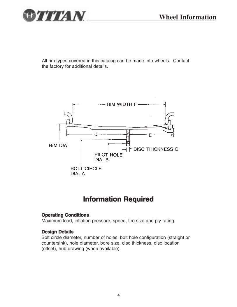
All rim types covered in this catalog can be made into wheels. Contactthe factory for additional details.
IInnffoorrmmaattiioonn RReeqquuiirreedd
OOppeerraattiinngg CCoonnddiittiioonnssMaximum load, inflation pressure, speed, tire size and ply rating.
DDeessiiggnn DDeettaaiillssBolt circle diameter, number of holes, bolt hole configuration (straight orcountersink), hole diameter, bore size, disc thickness, disc location (offset), hub drawing (when available).
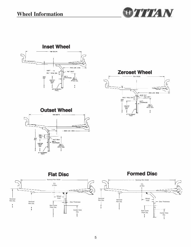
Wheel Information
5
IInnsseett WWhheeeell
ZZeerroosseett WWhheeeell
OOuuttsseett WWhheeeell
FFllaatt DDiisscc FFoorrmmeedd DDiisscc
Wheel Information
Nominal Rim Width Nominal Rim Width
Rim Width
Nominal Rim Dia.
Nominal Rim Dia. Nominal
Rim Dia.Nominal Rim Dia.
WheelInset
Disc Thickness Disc Thickness
Center HoleDia.
Center HoleDia.
Bolt CirclePitch Dia.
Bolt CirclePitch Dia.
C/Lof Rim
C/Lof Rim
WheelInset
6
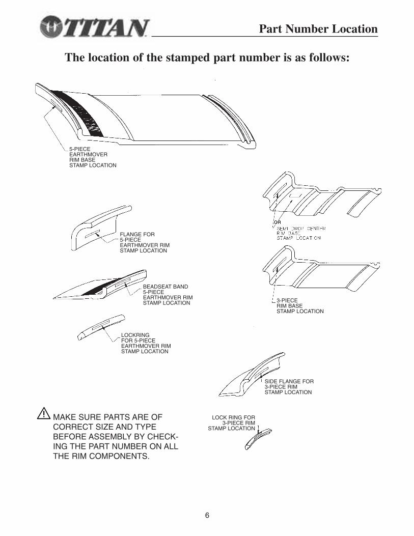
Part Number Location
MAKE SURE PARTS ARE OFCORRECT SIZE AND TYPEBEFORE ASSEMBLY BY CHECK-ING THE PART NUMBER ON ALLTHE RIM COMPONENTS.
The location of the stamped part number is as follows:
5-PIECEEARTHMOVERRIM BASESTAMP LOCATION
FLANGE FOR5-PIECEEARTHMOVER RIMSTAMP LOCATION
BEADSEAT BAND5-PIECEEARTHMOVER RIMSTAMP LOCATION
LOCKRINGFOR 5-PIECEEARTHMOVER RIMSTAMP LOCATION
3-PIECERIM BASESTAMP LOCATION
SIDE FLANGE FOR 3-PIECE RIM STAMP LOCATION
LOCK RING FOR 3-PIECE RIM
STAMP LOCATION
Identification/Terminology
7
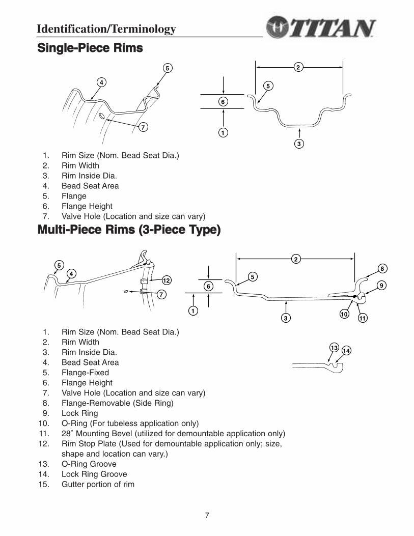
SSiinnggllee--PPiieeccee RRiimmss
1. Rim Size (Nom. Bead Seat Dia.)2. Rim Width3. Rim Inside Dia.4. Bead Seat Area5. Flange6. Flange Height7. Valve Hole (Location and size can vary)
MMuullttii--PPiieeccee RRiimmss ((33--PPiieeccee TTyyppee))
1. Rim Size (Nom. Bead Seat Dia.)2. Rim Width3. Rim Inside Dia.4. Bead Seat Area5. Flange-Fixed6. Flange Height7. Valve Hole (Location and size can vary)8. Flange-Removable (Side Ring)9. Lock Ring
10. O-Ring (For tubeless application only)11. 28˚ Mounting Bevel (utilized for demountable application only)12. Rim Stop Plate (Used for demountable application only; size,
shape and location can vary.)13. O-Ring Groove14. Lock Ring Groove15. Gutter portion of rim
4
5
6
1
5
7
3
2
5
58
96
412
7
13
1011
13 14
2
5
58
96
412
7
13
1011
13 14
2
5
58
96
412
7
13
1011
13 14
2
4
5
6
1
5
7
3
2
8
Identification/Terminology
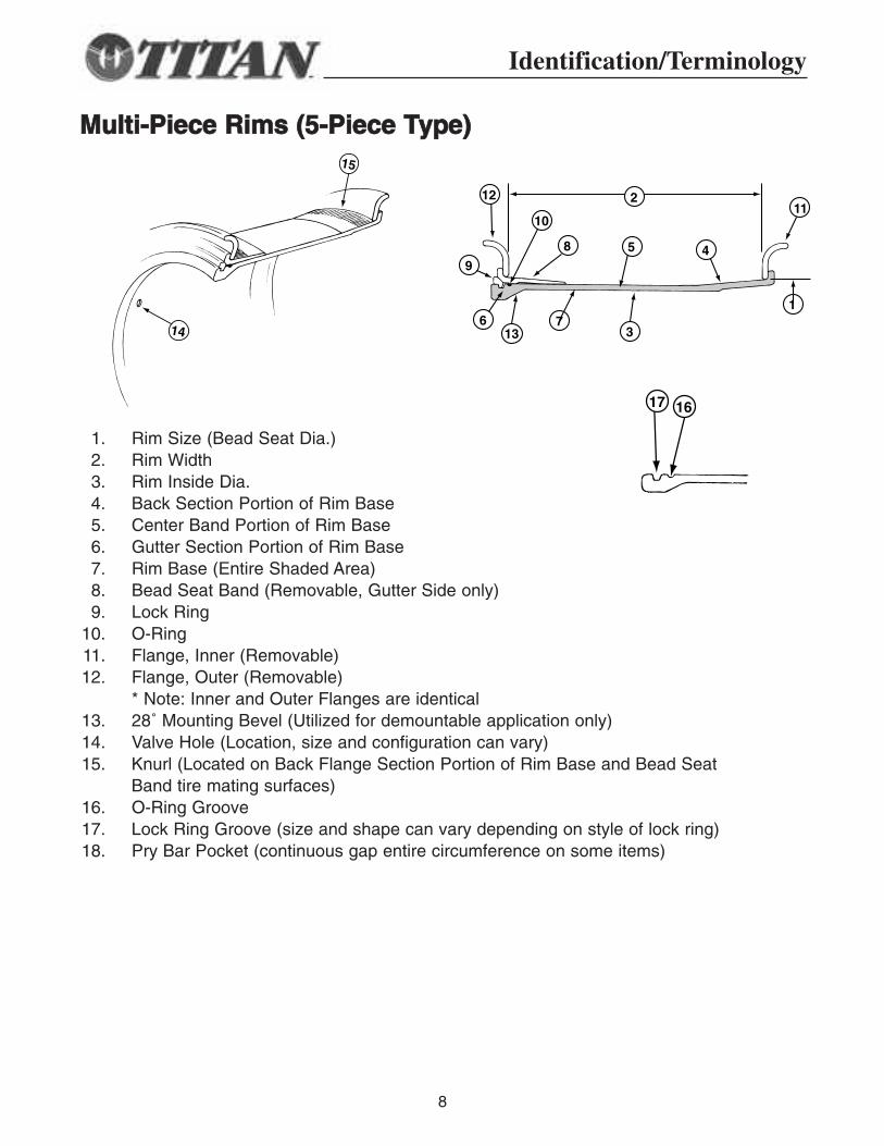
MMuullttii--PPiieeccee RRiimmss ((55--PPiieeccee TTyyppee))
1. Rim Size (Bead Seat Dia.)2. Rim Width3. Rim Inside Dia.4. Back Section Portion of Rim Base5. Center Band Portion of Rim Base6. Gutter Section Portion of Rim Base7. Rim Base (Entire Shaded Area)8. Bead Seat Band (Removable, Gutter Side only)9. Lock Ring
10. O-Ring11. Flange, Inner (Removable)12. Flange, Outer (Removable)
* Note: Inner and Outer Flanges are identical13. 28˚ Mounting Bevel (Utilized for demountable application only)14. Valve Hole (Location, size and configuration can vary)15. Knurl (Located on Back Flange Section Portion of Rim Base and Bead Seat
Band tire mating surfaces)16. O-Ring Groove17. Lock Ring Groove (size and shape can vary depending on style of lock ring)18. Pry Bar Pocket (continuous gap entire circumference on some items)
15
14
1617
5
12
9
613 7
8
10
4
11
1
2
3
15
14
1617
5
12
9
613
7
8
10
4
11
1
2
3
15
14
1617
5
12
9
613
7
8
10
4
11
1
2
3
9
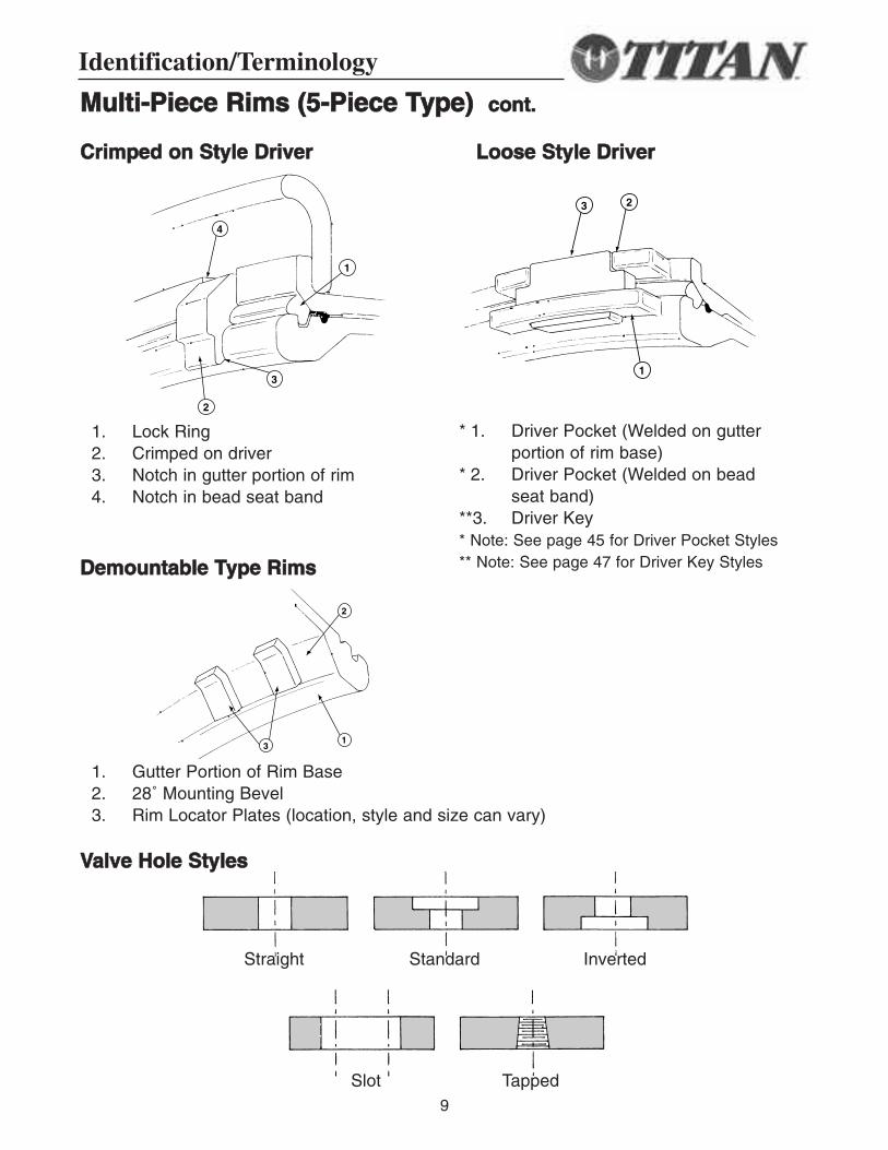
MMuullttii--PPiieeccee RRiimmss ((55--PPiieeccee TTyyppee)) ccoonntt..
1. Lock Ring2. Crimped on driver3. Notch in gutter portion of rim4. Notch in bead seat band
1. Gutter Portion of Rim Base2. 28˚ Mounting Bevel3. Rim Locator Plates (location, style and size can vary)
* 1. Driver Pocket (Welded on gutter portion of rim base)
* 2. Driver Pocket (Welded on bead seat band)
**3. Driver Key* Note: See page 45 for Driver Pocket Styles** Note: See page 47 for Driver Key Styles
CCrriimmppeedd oonn SSttyyllee DDrriivveerr
DDeemmoouunnttaabbllee TTyyppee RRiimmss
VVaallvvee HHoollee SSttyylleess
LLoooossee SSttyyllee DDrriivveerr
4
1
3
2
23
1
2
13
Straight Standard Inverted
Slot Tapped
Identification/Terminology
10
SS II NN GG LL EE -- PP II EE CC EE WW HH EE EE LL
11
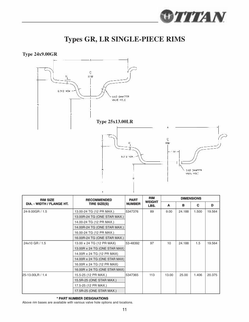
Types GR, LR SINGLE-PIECE RIMS
Type 24x9.00GR
DDIIMMEENNSSIIOONNSS
AA BB CC DD
24-9.00GR / 1.5 13.00-24 TG (12 PR MAX.) 5347376 89 9.00 24.188 1.500 19.564
13.00R-24 TG (ONE STAR MAX.)
14.00-24 TG (12 PR MAX.)
14.00R-24 TG (ONE STAR MAX.)
16.00-24 TG (12 PR MAX.)
16.00R-24 TG (ONE STAR MAX.)
24x10 GR / 1.5 13.00 x 24 TG (12 PR MAX) 53-48392 97 10 24.188 1.5 19.564
13.00R x 24 TG (ONE STAR MAX)
14.00R x 24 TG (12 PR MAX)
14.00R x 24 TG (ONE STAR MAX)
16.00R x 24 TG (12 PR MAX)
16.00R x 24 TG (ONE STAR MAX)
25-13.00LR / 1.4 15.5-25 (12 PR MAX.) 5347365 113 13.00 25.00 1.406 20.375
15.5R-25 (ONE STAR MAX.)
17.5-25 (12 PR MAX.)
17.5R-25 (ONE STAR MAX.)
** PPAARRTT NNUUMMBBEERR DDEESSIIGGNNAATTIIOONNSSAbove rim bases are available with various valve hole options and locations.
RRIIMM SSIIZZEEDDIIAA.. -- WWIIDDTTHH // FFLLAANNGGEE HHTT..
RREECCOOMMMMEENNDDEEDDTTIIRREE SSIIZZEE((SS))
PPAARRTTNNUUMMBBEERR
RRIIMMWWEEIIGGHHTT
LLBBSS..
Type 25x13.00LR
12
33 -- PP II EE CC EE RR II MM AA SS SS EE MM BB LL II EE SS
13
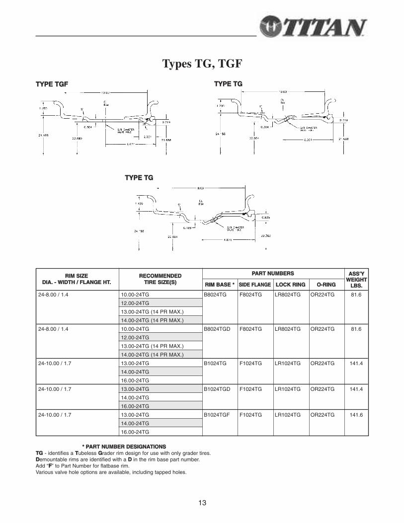
Types TG, TGF
TTYYPPEE TTGGFF TTYYPPEE TTGG
TTYYPPEE TTGG
PPAARRTT NNUUMMBBEERRSS
RRIIMM BBAASSEE ** SSIIDDEE FFLLAANNGGEE LLOOCCKK RRIINNGG OO--RRIINNGG
24-8.00 / 1.4 10.00-24TG B8024TG F8024TG LR8024TG OR224TG 81.6
12.00-24TG
13.00-24TG (14 PR MAX.)
14.00-24TG (14 PR MAX.)
24-8.00 / 1.4 10.00-24TG B8024TGD F8024TG LR8024TG OR224TG 81.6
12.00-24TG
13.00-24TG (14 PR MAX.)
14.00-24TG (14 PR MAX.)
24-10.00 / 1.7 13.00-24TG B1024TG F1024TG LR1024TG OR224TG 141.4
14.00-24TG
16.00-24TG
24-10.00 / 1.7 13.00-24TG B1024TGD F1024TG LR1024TG OR224TG 141.4
14.00-24TG
16.00-24TG
24-10.00 / 1.7 13.00-24TG B1024TGF F1024TG LR1024TG OR224TG 141.6
14.00-24TG
16.00-24TG
** PPAARRTT NNUUMMBBEERR DDEESSIIGGNNAATTIIOONNSSTTGG - identifies a TTubeless GGrader rim design for use with only grader tires.DDemountable rims are identified with a DD in the rim base part number.Add “FF” to Part Number for flatbase rim.Various valve hole options are available, including tapped holes.
RRIIMM SSIIZZEEDDIIAA.. -- WWIIDDTTHH // FFLLAANNGGEE HHTT..
RREECCOOMMMMEENNDDEEDDTTIIRREE SSIIZZEE((SS))
AASSSS’’YYWWEEIIGGHHTT
LLBBSS..
14
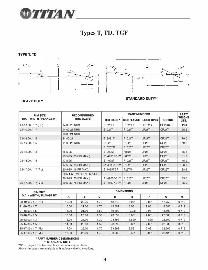
Types T, TD, TGF
TTYYPPEE TT,, TTDD
SSTTAANNDDAARRDD DDUUTTYY****
PPAARRTT NNUUMMBBEERRSS
RRIIMM BBAASSEE ** SSIIDDEE FFLLAANNGGEE LLOOCCKK RRIINNGG OO--RRIINNGG
20-10.00 / 1.7 (HF) 14.00-20 NHS B1020HF F1020HF LR1020G OR220TG 119.4
21-10.00 / 1.7 14.00-21 NHS B1021T F1021T LR21T OR21T 125.2
16.00-21 NHS
21-18.00 / 1.5 24.00-21 B18021T F1021T LR21T OR21T 170.0
25-10.00 / 1.5 14.00-25 NHS B1025T F1025T LR25T OR25T 149.2
B1025TD F1025T LR25T OR25T
25-12.00 / 1.3 15.5-25 B12025T F8525T LR25T OR25T 135.8
15.5-25 (75 PSI MAX.) 51-49055-01** F8525T LR25T OR25T 101.0
25-14.00 / 1.5 17.5-25 B14025T F1025T LR25T OR25T 175.9
17.5-25 (75 PSI MAX.) 51-48933-01** F1025T LR25T OR25T 126.0
25-17.00 / 1.7 (AL) 20.5-25 (16 PR MAX.) B17025TGF F25TG LR25T OR25T 188.2
20.5R25 (ONE STAR MAX.)
20.5-25 (75 PSI MAX.) 51-49050-01** F1025T LR25T OR25T 135.0
25-17.00 / 1.7 (VL) 20.5-25 (75 PSI MAX.) 51-48937-01** F1025T LR25T OR25T 135.0
** PPAARRTT NNUUMMBBEERR DDEESSIIGGNNAATTIIOONNSS**** SSTTAANNDDAARRDD DDUUTTYY
““DD”” in the part number denotes a demountable rim baseAbove rim bases are available with various valve hole options.
RRIIMM SSIIZZEEDDIIAA.. -- WWIIDDTTHH // FFLLAANNGGEE HHTT..
RREECCOOMMMMEENNDDEEDDTTIIRREE SSIIZZEE((SS))
AASSSS’’YYWWEEIIGGHHTT
LLBBSS..
DDIIMMEENNSSIIOONNSS
AA BB CC DD EE FF GG HH
20-10.00 / 1.7 (HF) 10.00 20.25 1.70 18.642 6.031 2.031 17.750 0.719
21-10.00 / 1.7 10.00 21.00 1.70 19.392 6.031 2.031 18.500 0.719
21-18.00 / 1.5 18.00 21.00 1.50 19.392 10.031 2.031 18.500 0.719
25-10.00 / 1.5 10.00 25.00 1.50 23.392 6.031 2.031 22.500 0.719
25-12.00 / 1.3 12.00 25.00 1.30 23.392 6.890 1.898 22.500 0.719
25-14.00 / 1.5 14.00 25.00 1.50 23.392 8.031 2.031 22.500 0.719
25-17.00 / 1.7 (AL) 17.00 25.00 1.70 23.392 9.531 2.031 22.500 0.719
25-17.00 / 1.7 (VL) 17.00 25.00 1.70 23.300 9.531 2.031 22.425 0.719
RRIIMM SSIIZZEEDDIIAA.. -- WWIIDDTTHH // FFLLAANNGGEE HHTT..
HHEEAAVVYY DDUUTTYY
15
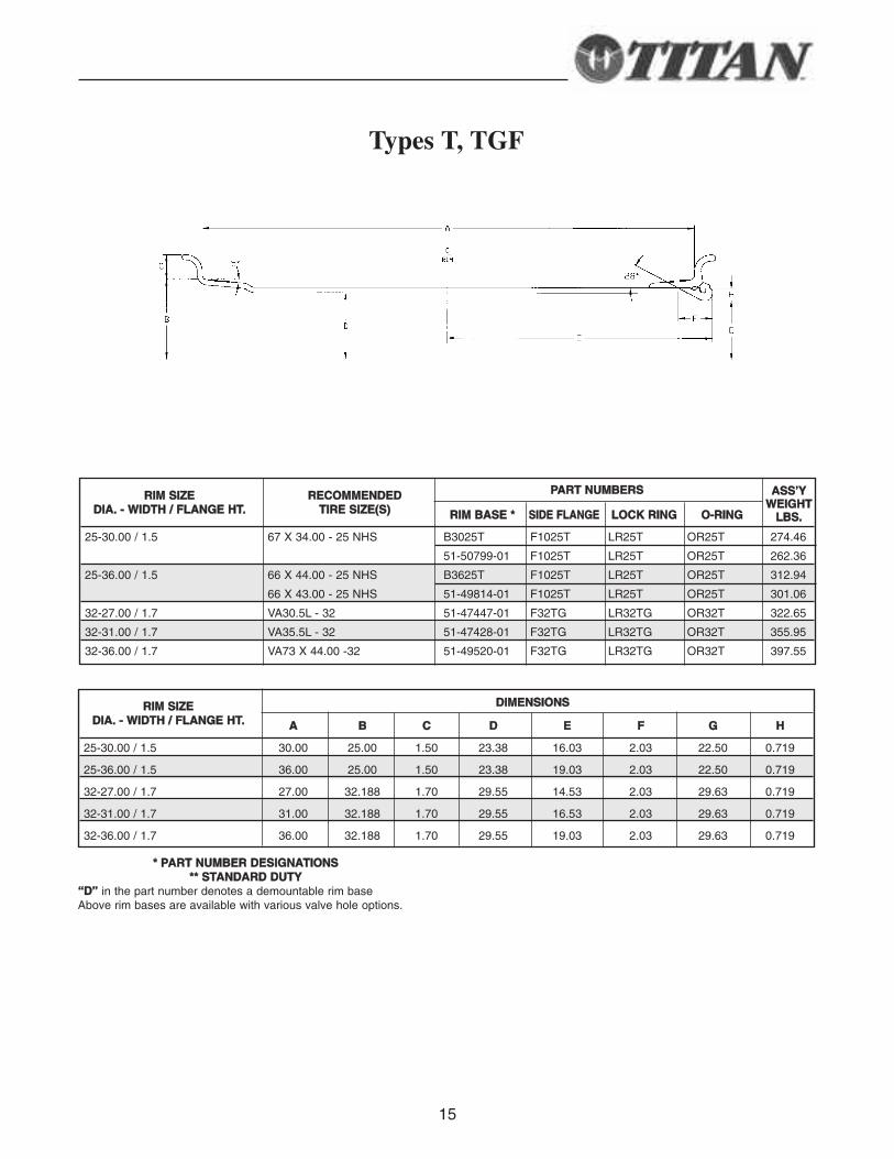
Types T, TGF
PPAARRTT NNUUMMBBEERRSS
RRIIMM BBAASSEE ** SSIIDDEE FFLLAANNGGEE LLOOCCKK RRIINNGG OO--RRIINNGG
25-30.00 / 1.5 67 X 34.00 - 25 NHS B3025T F1025T LR25T OR25T 274.46
51-50799-01 F1025T LR25T OR25T 262.36
25-36.00 / 1.5 66 X 44.00 - 25 NHS B3625T F1025T LR25T OR25T 312.94
66 X 43.00 - 25 NHS 51-49814-01 F1025T LR25T OR25T 301.06
32-27.00 / 1.7 VA30.5L - 32 51-47447-01 F32TG LR32TG OR32T 322.65
32-31.00 / 1.7 VA35.5L - 32 51-47428-01 F32TG LR32TG OR32T 355.95
32-36.00 / 1.7 VA73 X 44.00 -32 51-49520-01 F32TG LR32TG OR32T 397.55
** PPAARRTT NNUUMMBBEERR DDEESSIIGGNNAATTIIOONNSS**** SSTTAANNDDAARRDD DDUUTTYY
““DD”” in the part number denotes a demountable rim baseAbove rim bases are available with various valve hole options.
RRIIMM SSIIZZEEDDIIAA.. -- WWIIDDTTHH // FFLLAANNGGEE HHTT..
RREECCOOMMMMEENNDDEEDDTTIIRREE SSIIZZEE((SS))
AASSSS’’YYWWEEIIGGHHTT
LLBBSS..
DDIIMMEENNSSIIOONNSS
AA BB CC DD EE FF GG HH
25-30.00 / 1.5 30.00 25.00 1.50 23.38 16.03 2.03 22.50 0.719
25-36.00 / 1.5 36.00 25.00 1.50 23.38 19.03 2.03 22.50 0.719
32-27.00 / 1.7 27.00 32.188 1.70 29.55 14.53 2.03 29.63 0.719
32-31.00 / 1.7 31.00 32.188 1.70 29.55 16.53 2.03 29.63 0.719
32-36.00 / 1.7 36.00 32.188 1.70 29.55 19.03 2.03 29.63 0.719
RRIIMM SSIIZZEEDDIIAA.. -- WWIIDDTTHH // FFLLAANNGGEE HHTT..
16
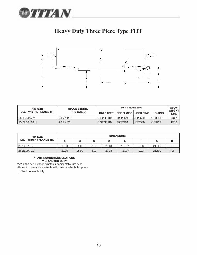
Heavy Duty Three Piece Type FHT
** PPAARRTT NNUUMMBBEERR DDEESSIIGGNNAATTIIOONNSS**** SSTTAANNDDAARRDD DDUUTTYY
““DD”” in the part number denotes a demountable rim baseAbove rim bases are available with various valve hole options.
† Check for availability.
DDIIMMEENNSSIIOONNSS
AA BB CC DD EE FF GG HH
25-19.5 / 2.5 19.50 25.00 2.50 23.38 11.687 2.03 21.500 1.06
25-22.00 / 3.0 22.00 25.00 3.00 23.38 12.937 2.03 21.500 1.06
RRIIMM SSIIZZEEDDIIAA.. -- WWIIDDTTHH // FFLLAANNGGEE HHTT..
PPAARRTT NNUUMMBBEERRSS
RRIIMM BBAASSEE ** SSIIDDEE FFLLAANNGGEE LLOOCCKK RRIINNGG OO--RRIINNGG
25-19.5/2.5 † 23.5 X 25 B1925FHTM F2525SM LR255TM OR325T 383.7
25-22.00 /3.0 † 26.5 X 25 B2225FHTM F3025SM LR255TM OR325T 472.6
RRIIMM SSIIZZEEDDIIAA.. -- WWIIDDTTHH // FFLLAANNGGEE HHTT..
RREECCOOMMMMEENNDDEEDDTTIIRREE SSIIZZEE((SS))
AASSSS’’YYWWEEIIGGHHTT
LLBBSS..
17
55 -- PP II EE CC EE RR II MM AA SS SS EE MM BB LL II EE SS
18
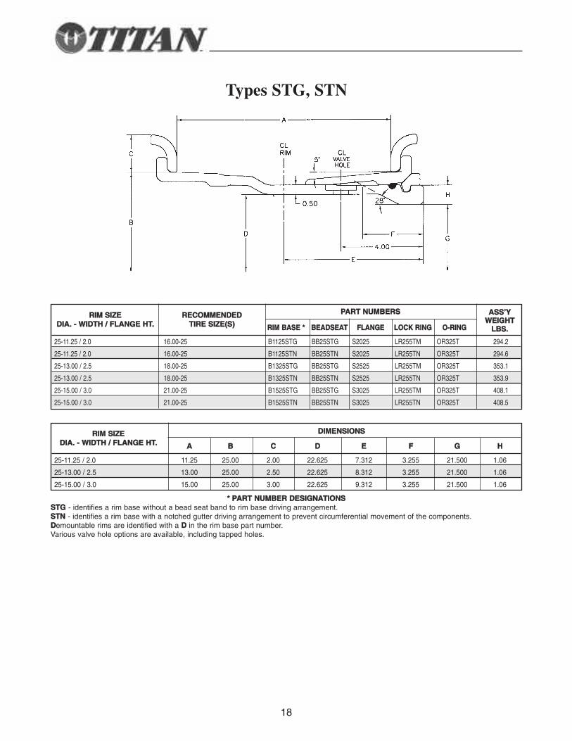
Types STG, STN
PPAARRTT NNUUMMBBEERRSS
RRIIMM BBAASSEE ** BBEEAADDSSEEAATT FFLLAANNGGEE LLOOCCKK RRIINNGG OO--RRIINNGG
25-11.25 / 2.0 16.00-25 B1125STG BB25STG S2025 LR255TM OR325T 294.2
25-11.25 / 2.0 16.00-25 B1125STN BB25STN S2025 LR255TN OR325T 294.6
25-13.00 / 2.5 18.00-25 B1325STG BB25STG S2525 LR255TM OR325T 353.1
25-13.00 / 2.5 18.00-25 B1325STN BB25STN S2525 LR255TN OR325T 353.9
25-15.00 / 3.0 21.00-25 B1525STG BB25STG S3025 LR255TM OR325T 408.1
25-15.00 / 3.0 21.00-25 B1525STN BB25STN S3025 LR255TN OR325T 408.5
** PPAARRTT NNUUMMBBEERR DDEESSIIGGNNAATTIIOONNSSSSTTGG - identifies a rim base without a bead seat band to rim base driving arrangement.SSTTNN - identifies a rim base with a notched gutter driving arrangement to prevent circumferential movement of the components.DDemountable rims are identified with a DD in the rim base part number.Various valve hole options are available, including tapped holes.
RRIIMM SSIIZZEEDDIIAA.. -- WWIIDDTTHH // FFLLAANNGGEE HHTT..
RREECCOOMMMMEENNDDEEDDTTIIRREE SSIIZZEE((SS))
AASSSS’’YYWWEEIIGGHHTT
LLBBSS..
DDIIMMEENNSSIIOONNSS
AA BB CC DD EE FF GG HH
25-11.25 / 2.0 11.25 25.00 2.00 22.625 7.312 3.255 21.500 1.06
25-13.00 / 2.5 13.00 25.00 2.50 22.625 8.312 3.255 21.500 1.06
25-15.00 / 3.0 15.00 25.00 3.00 22.625 9.312 3.255 21.500 1.06
RRIIMM SSIIZZEEDDIIAA.. -- WWIIDDTTHH // FFLLAANNGGEE HHTT..
19
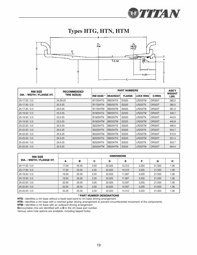
Types HTG, HTN, HTM
PPAARRTT NNUUMMBBEERRSS
RRIIMM BBAASSEE ** BBEEAADDSSEEAATT FFLLAANNGGEE LLOOCCKK RRIINNGG OO--RRIINNGG
25-17.00 / 3.5 24.00-25 B1725HTG BB25HTG S3525 LR255TM OR325T 380.0
25-17.00 / 2.0 20.5-25 B1725HTN BB25STN S2025 LR255TN OR325T 380.0
25-17.00 / 2.0 20.5-25 B1725HTM BB25STM S2025 LR255TM OR325T 381.9
25-19.50 / 2.5 23.5-25 B1925HTG BB25STG S2525 LR255TM OR325T 446.7
25-19.50 / 2.5 23.5-25 B1925HTN BB25STN S2525 LR255TN OR325T 443.9
25-19.50 / 2.5 23.5-25 B1925HTM BB25STM S2525 LR255TM OR325T 445.8
25-22.00 / 3.0 26.5-25 B2225HTG BB25HTG S3025 LR255TM OR325T 499.0
25-22.00 / 3.0 26.5-25 B2225HTN BB25HTN S3025 LR255TN OR325T 504.7
25-22.00 / 3.0 26.5-25 B2225HTM BB25HTM S3025 LR255TM OR325T 515.9
25-25.00 / 3.5 29.5-25 B2525HTG BB25HTG S3525 LR255TM OR325T 551.4
25-25.00 / 3.5 29.5-25 B2525HTN BB25HTN S3525 LR255TN OR325T 553.7
25-25.00 / 3.5 29.5-25 B2525HTM BB25HTM S3525 LR255TM OR325T 564.4
** PPAARRTT NNUUMMBBEERR DDEESSIIGGNNAATTIIOONNSSHHTTGG -- identifies a rim base without a bead seat band to rim base driving arrangement.HHTTNN -- identifies a rim base with a notched gutter driving arrangement to prevent circumferential movement of the components.HHTTMM -- identifies a rim base with an outboard driving arrangement.DDemountable rims are identified with a DD in the rim base part number.Various valve hole options are available, including tapped holes.
RRIIMM SSIIZZEEDDIIAA.. -- WWIIDDTTHH // FFLLAANNGGEE HHTT..
RREECCOOMMMMEENNDDEEDDTTIIRREE SSIIZZEE((SS))
AASSSS’’YYWWEEIIGGHHTT
LLBBSS..
DDIIMMEENNSSIIOONNSS
AA BB CC DD EE FF GG HH
25-17.00 / 3.5 17.00 25.00 3.50 22.625 10.312 3.255 21.500 1.06
25-17.00 / 2.0 17.00 25.00 2.00 22.625 10.312 3.255 21.500 1.06
25-19.50 / 2.5 19.50 25.00 2.50 22.625 11.687 3.255 21.500 1.06
25-19.50 / 2.5 19.50 25.00 2.50 22.625 11.687 3.255 21.500 1.06
25-22.00 / 3.0 22.00 25.00 3.00 22.625 12.937 3.255 21.500 1.06
25-22.00 / 3.0 22.00 25.00 3.00 22.625 12.937 3.255 21.500 1.06
25-25.00 / 3.5 25.00 25.00 3.50 22.625 14.312 3.255 21.500 1.06
RRIIMM SSIIZZEEDDIIAA.. -- WWIIDDTTHH // FFLLAANNGGEE HHTT..
20
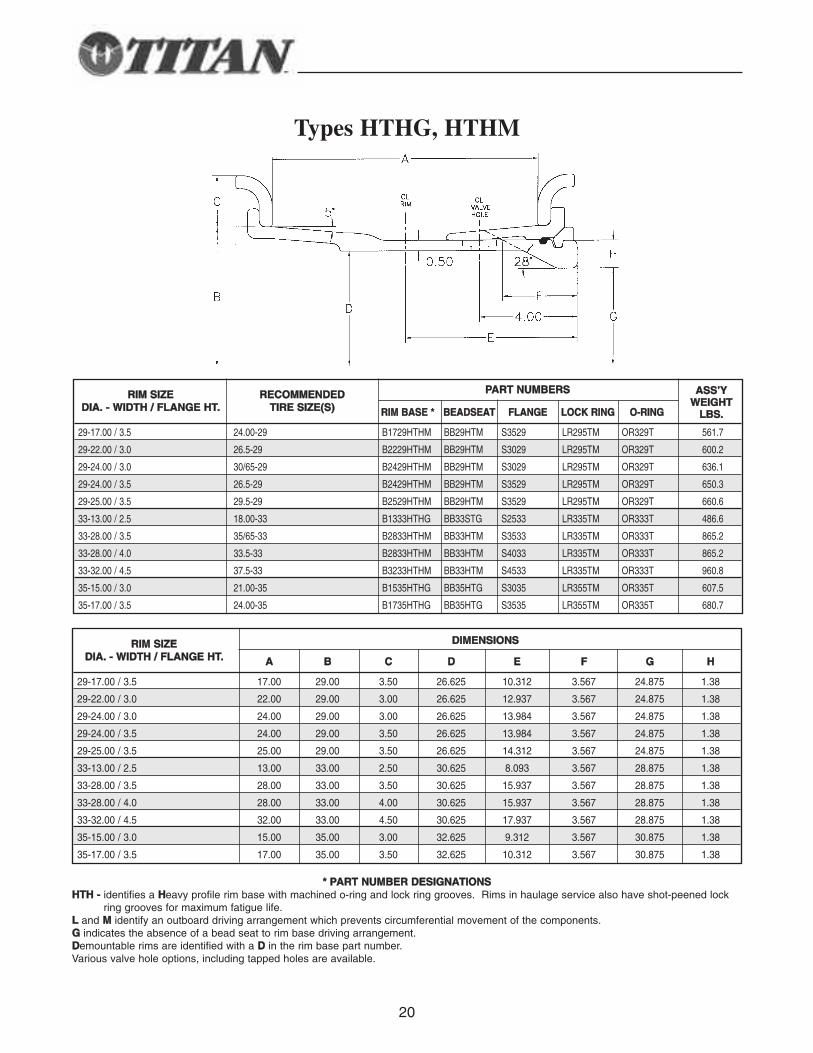
Types HTHG, HTHM
PPAARRTT NNUUMMBBEERRSS
RRIIMM BBAASSEE ** BBEEAADDSSEEAATT FFLLAANNGGEE LLOOCCKK RRIINNGG OO--RRIINNGG
29-17.00 / 3.5 24.00-29 B1729HTHM BB29HTM S3529 LR295TM OR329T 561.7
29-22.00 / 3.0 26.5-29 B2229HTHM BB29HTM S3029 LR295TM OR329T 600.2
29-24.00 / 3.0 30/65-29 B2429HTHM BB29HTM S3029 LR295TM OR329T 636.1
29-24.00 / 3.5 26.5-29 B2429HTHM BB29HTM S3529 LR295TM OR329T 650.3
29-25.00 / 3.5 29.5-29 B2529HTHM BB29HTM S3529 LR295TM OR329T 660.6
33-13.00 / 2.5 18.00-33 B1333HTHG BB33STG S2533 LR335TM OR333T 486.6
33-28.00 / 3.5 35/65-33 B2833HTHM BB33HTM S3533 LR335TM OR333T 865.2
33-28.00 / 4.0 33.5-33 B2833HTHM BB33HTM S4033 LR335TM OR333T 865.2
33-32.00 / 4.5 37.5-33 B3233HTHM BB33HTM S4533 LR335TM OR333T 960.8
35-15.00 / 3.0 21.00-35 B1535HTHG BB35HTG S3035 LR355TM OR335T 607.5
35-17.00 / 3.5 24.00-35 B1735HTHG BB35HTG S3535 LR355TM OR335T 680.7
** PPAARRTT NNUUMMBBEERR DDEESSIIGGNNAATTIIOONNSSHHTTHH -- identifies a HHeavy profile rim base with machined o-ring and lock ring grooves. Rims in haulage service also have shot-peened lock
ring grooves for maximum fatigue life.LL and MM identify an outboard driving arrangement which prevents circumferential movement of the components.GG indicates the absence of a bead seat to rim base driving arrangement.DDemountable rims are identified with a DD in the rim base part number.Various valve hole options, including tapped holes are available.
RRIIMM SSIIZZEEDDIIAA.. -- WWIIDDTTHH // FFLLAANNGGEE HHTT..
RREECCOOMMMMEENNDDEEDDTTIIRREE SSIIZZEE((SS))
AASSSS’’YYWWEEIIGGHHTT
LLBBSS..
DDIIMMEENNSSIIOONNSS
AA BB CC DD EE FF GG HH
29-17.00 / 3.5 17.00 29.00 3.50 26.625 10.312 3.567 24.875 1.38
29-22.00 / 3.0 22.00 29.00 3.00 26.625 12.937 3.567 24.875 1.38
29-24.00 / 3.0 24.00 29.00 3.00 26.625 13.984 3.567 24.875 1.38
29-24.00 / 3.5 24.00 29.00 3.50 26.625 13.984 3.567 24.875 1.38
29-25.00 / 3.5 25.00 29.00 3.50 26.625 14.312 3.567 24.875 1.38
33-13.00 / 2.5 13.00 33.00 2.50 30.625 8.093 3.567 28.875 1.38
33-28.00 / 3.5 28.00 33.00 3.50 30.625 15.937 3.567 28.875 1.38
33-28.00 / 4.0 28.00 33.00 4.00 30.625 15.937 3.567 28.875 1.38
33-32.00 / 4.5 32.00 33.00 4.50 30.625 17.937 3.567 28.875 1.38
35-15.00 / 3.0 15.00 35.00 3.00 32.625 9.312 3.567 30.875 1.38
35-17.00 / 3.5 17.00 35.00 3.50 32.625 10.312 3.567 30.875 1.38
RRIIMM SSIIZZEEDDIIAA.. -- WWIIDDTTHH // FFLLAANNGGEE HHTT..
21
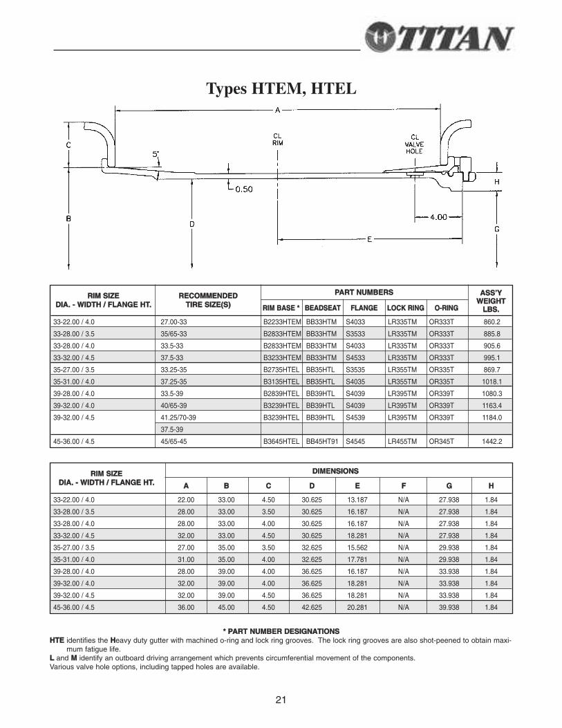
Types HTEM, HTEL
PPAARRTT NNUUMMBBEERRSS
RRIIMM BBAASSEE ** BBEEAADDSSEEAATT FFLLAANNGGEE LLOOCCKK RRIINNGG OO--RRIINNGG
33-22.00 / 4.0 27.00-33 B2233HTEM BB33HTM S4033 LR335TM OR333T 860.2
33-28.00 / 3.5 35/65-33 B2833HTEM BB33HTM S3533 LR335TM OR333T 885.8
33-28.00 / 4.0 33.5-33 B2833HTEM BB33HTM S4033 LR335TM OR333T 905.6
33-32.00 / 4.5 37.5-33 B3233HTEM BB33HTM S4533 LR335TM OR333T 995.1
35-27.00 / 3.5 33.25-35 B2735HTEL BB35HTL S3535 LR355TM OR335T 869.7
35-31.00 / 4.0 37.25-35 B3135HTEL BB35HTL S4035 LR355TM OR335T 1018.1
39-28.00 / 4.0 33.5-39 B2839HTEL BB39HTL S4039 LR395TM OR339T 1080.3
39-32.00 / 4.0 40/65-39 B3239HTEL BB39HTL S4039 LR395TM OR339T 1163.4
39-32.00 / 4.5 41.25/70-39 B3239HTEL BB39HTL S4539 LR395TM OR339T 1184.0
37.5-39
45-36.00 / 4.5 45/65-45 B3645HTEL BB45HT91 S4545 LR455TM OR345T 1442.2
** PPAARRTT NNUUMMBBEERR DDEESSIIGGNNAATTIIOONNSSHHTTEE identifies the HHeavy duty gutter with machined o-ring and lock ring grooves. The lock ring grooves are also shot-peened to obtain maxi-
mum fatigue life.LL and MM identify an outboard driving arrangement which prevents circumferential movement of the components.Various valve hole options, including tapped holes are available.
RRIIMM SSIIZZEEDDIIAA.. -- WWIIDDTTHH // FFLLAANNGGEE HHTT..
RREECCOOMMMMEENNDDEEDDTTIIRREE SSIIZZEE((SS))
AASSSS’’YYWWEEIIGGHHTT
LLBBSS..
DDIIMMEENNSSIIOONNSS
AA BB CC DD EE FF GG HH
33-22.00 / 4.0 22.00 33.00 4.50 30.625 13.187 N/A 27.938 1.84
33-28.00 / 3.5 28.00 33.00 3.50 30.625 16.187 N/A 27.938 1.84
33-28.00 / 4.0 28.00 33.00 4.00 30.625 16.187 N/A 27.938 1.84
33-32.00 / 4.5 32.00 33.00 4.50 30.625 18.281 N/A 27.938 1.84
35-27.00 / 3.5 27.00 35.00 3.50 32.625 15.562 N/A 29.938 1.84
35-31.00 / 4.0 31.00 35.00 4.00 32.625 17.781 N/A 29.938 1.84
39-28.00 / 4.0 28.00 39.00 4.00 36.625 16.187 N/A 33.938 1.84
39-32.00 / 4.0 32.00 39.00 4.00 36.625 18.281 N/A 33.938 1.84
39-32.00 / 4.5 32.00 39.00 4.50 36.625 18.281 N/A 33.938 1.84
45-36.00 / 4.5 36.00 45.00 4.50 42.625 20.281 N/A 39.938 1.84
RRIIMM SSIIZZEEDDIIAA.. -- WWIIDDTTHH // FFLLAANNGGEE HHTT..
22
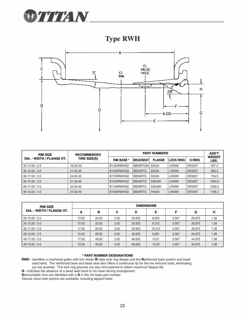
Type RWH
PPAARRTT NNUUMMBBEERRSS
RRIIMM BBAASSEE ** BBEEAADDSSEEAATT FFLLAANNGGEE LLOOCCKK RRIINNGG OO--RRIINNGG
33-13.00 / 2.5 18.00-33 B1333RWHGD BB33RTGN S2533 LR33W OR333T 557.2
35-15.00 / 3.0 21.00-35 B1535RWHGD BB35RTG S3035 LR35W OR335T 669.3
35-17.00 / 3.5 24.00-35 B1735RWHGD BB35RTG S3535 LR35W OR335T 734.5
49-15.00 / 3.0 21.00-49 B1549RWHGD BB49RTG S3049H LR49W OR349T 1004.6
49-17.00 / 3.5 24.00-49 B1749RWHGD BB49RTG S3549H LR49W OR349T 1099.5
49-19.50 / 4.0 27.00-49 B1949RWHGD BB49RTG H4049 LR49W OR349T 1196.2
** PPAARRTT NNUUMMBBEERR DDEESSIIGGNNAATTIIOONNSSRRWWHH - identifies a machined gutter with low stress WW style lock ring design and the RReinforced back section and bead
seat band. The reinforced back and bead seat also offers a continuous lip for the tire removal tools, eliminatingpry bar pockets. The lock ring grooves are also shot-peened to obtain maximum fatigue life.
GG -- indicates the absence of a bead seat band to rim base driving arrangement.DDemountable rims are identified with a DD in the rim base part number.Various valve hole options are available, including tapped holes.
RRIIMM SSIIZZEEDDIIAA.. -- WWIIDDTTHH // FFLLAANNGGEE HHTT..
RREECCOOMMMMEENNDDEEDDTTIIRREE SSIIZZEE((SS))
AASSSS’’YYWWEEIIGGHHTT
LLBBSS..
DDIIMMEENNSSIIOONNSS
AA BB CC DD EE FF GG HH
33-13.00 / 2.5 13.00 33.00 2.50 30.625 8.093 3.567 28.875 1.38
35-15.00 / 3.0 15.00 35.00 3.00 32.625 9.312 3.567 30.875 1.38
35-17.00 / 3.5 17.00 35.00 3.50 32.625 10.312 3.567 30.875 1.38
49-15.00 / 3.0 15.00 49.00 3.00 46.625 9.281 3.567 44.875 1.38
49-17.00 / 3.5 17.00 49.00 3.50 46.625 10.61 3.567 44.875 1.38
49-19.50 / 4.0 19.50 49.00 4.00 46.625 12.00 3.567 44.875 1.38
RRIIMM SSIIZZEEDDIIAA.. -- WWIIDDTTHH // FFLLAANNGGEE HHTT..
23
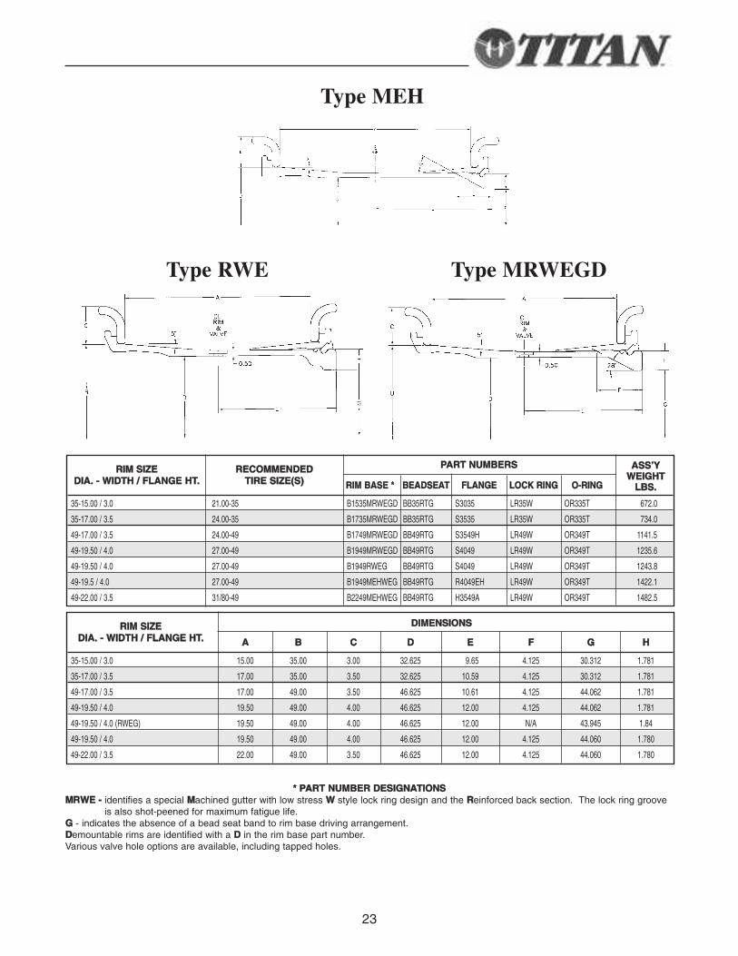
Type RWE Type MRWEGD
Type MEH
PPAARRTT NNUUMMBBEERRSS
RRIIMM BBAASSEE ** BBEEAADDSSEEAATT FFLLAANNGGEE LLOOCCKK RRIINNGG OO--RRIINNGG
35-15.00 / 3.0 21.00-35 B1535MRWEGD BB35RTG S3035 LR35W OR335T 672.0
35-17.00 / 3.5 24.00-35 B1735MRWEGD BB35RTG S3535 LR35W OR335T 734.0
49-17.00 / 3.5 24.00-49 B1749MRWEGD BB49RTG S3549H LR49W OR349T 1141.5
49-19.50 / 4.0 27.00-49 B1949MRWEGD BB49RTG S4049 LR49W OR349T 1235.6
49-19.50 / 4.0 27.00-49 B1949RWEG BB49RTG S4049 LR49W OR349T 1243.8
49-19.5 / 4.0 27.00-49 B1949MEHWEG BB49RTG R4049EH LR49W OR349T 1422.1
49-22.00 / 3.5 31/80-49 B2249MEHWEG BB49RTG H3549A LR49W OR349T 1482.5
** PPAARRTT NNUUMMBBEERR DDEESSIIGGNNAATTIIOONNSSMMRRWWEE -- identifies a special MMachined gutter with low stress WW style lock ring design and the RReinforced back section. The lock ring groove
is also shot-peened for maximum fatigue life.GG - indicates the absence of a bead seat band to rim base driving arrangement.DDemountable rims are identified with a DD in the rim base part number.Various valve hole options are available, including tapped holes.
RRIIMM SSIIZZEEDDIIAA.. -- WWIIDDTTHH // FFLLAANNGGEE HHTT..
RREECCOOMMMMEENNDDEEDDTTIIRREE SSIIZZEE((SS))
AASSSS’’YYWWEEIIGGHHTT
LLBBSS..
DDIIMMEENNSSIIOONNSS
AA BB CC DD EE FF GG HH
35-15.00 / 3.0 15.00 35.00 3.00 32.625 9.65 4.125 30.312 1.781
35-17.00 / 3.5 17.00 35.00 3.50 32.625 10.59 4.125 30.312 1.781
49-17.00 / 3.5 17.00 49.00 3.50 46.625 10.61 4.125 44.062 1.781
49-19.50 / 4.0 19.50 49.00 4.00 46.625 12.00 4.125 44.062 1.781
49-19.50 / 4.0 (RWEG) 19.50 49.00 4.00 46.625 12.00 N/A 43.945 1.84
49-19.50 / 4.0 19.50 49.00 4.00 46.625 12.00 4.125 44.060 1.780
49-22.00 / 3.5 22.00 49.00 3.50 46.625 12.00 4.125 44.060 1.780
RRIIMM SSIIZZEEDDIIAA.. -- WWIIDDTTHH // FFLLAANNGGEE HHTT..
24
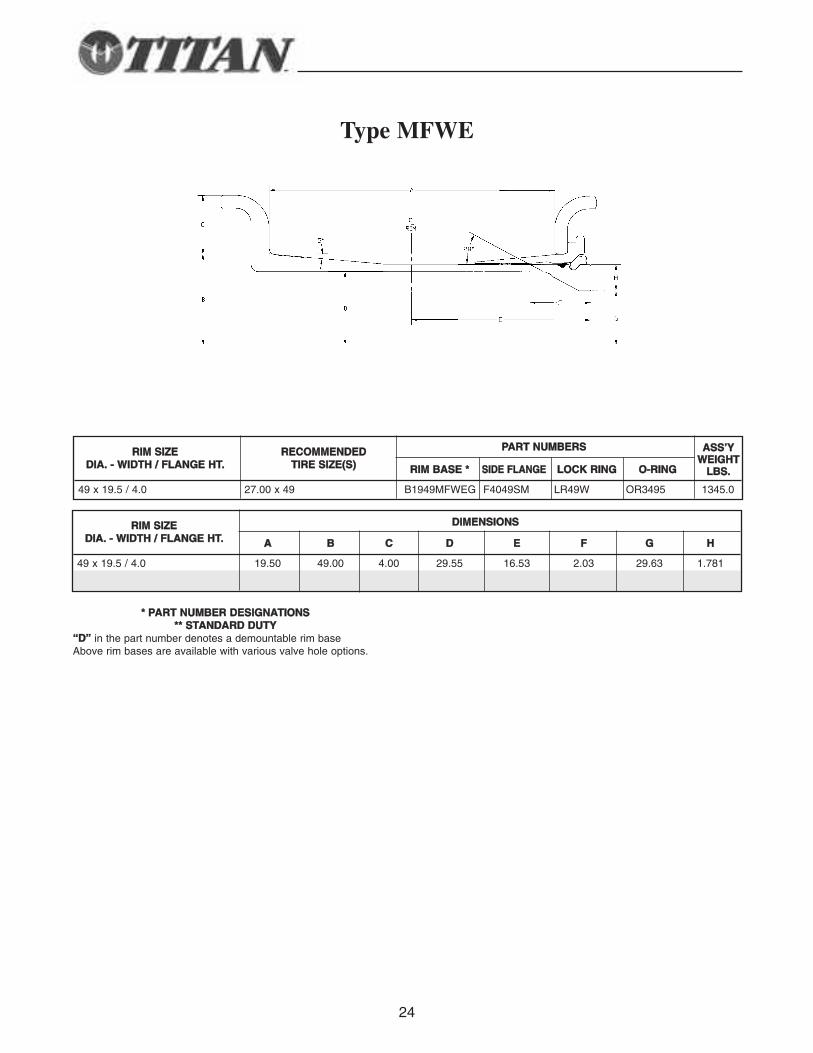
Type MFWE
** PPAARRTT NNUUMMBBEERR DDEESSIIGGNNAATTIIOONNSS**** SSTTAANNDDAARRDD DDUUTTYY
““DD”” in the part number denotes a demountable rim baseAbove rim bases are available with various valve hole options.
DDIIMMEENNSSIIOONNSS
AA BB CC DD EE FF GG HH
49 x 19.5 / 4.0 19.50 49.00 4.00 29.55 16.53 2.03 29.63 1.781
RRIIMM SSIIZZEEDDIIAA.. -- WWIIDDTTHH // FFLLAANNGGEE HHTT..
PPAARRTT NNUUMMBBEERRSS
RRIIMM BBAASSEE ** SSIIDDEE FFLLAANNGGEE LLOOCCKK RRIINNGG OO--RRIINNGG
49 x 19.5 / 4.0 27.00 x 49 B1949MFWEG F4049SM LR49W OR3495 1345.0
RRIIMM SSIIZZEEDDIIAA.. -- WWIIDDTTHH // FFLLAANNGGEE HHTT..
RREECCOOMMMMEENNDDEEDDTTIIRREE SSIIZZEE((SS))
AASSSS’’YYWWEEIIGGHHTT
LLBBSS..
25
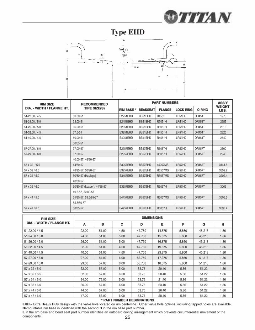
Type EHD
** PPAARRTT NNUUMMBBEERR DDEESSIIGGNNAATTIIOONNSSEEHHDD -- EExtra HHeavy DDuty design with the valve hole located on rim centerline. Other valve hole options, including tapped holes are available.DDemountable rim base is identified with the second DD in the rim base part number.LL in the rim base and bead seat part number identifies an outboard driving arrangement which prevents circumferential movement of thecomponents.
DDIIMMEENNSSIIOONNSS
AA BB CC DD EE FF GG HH
51-22.00 / 4.5 22.00 51.00 4.50 47.750 14.875 5.860 45.218 1.86
51-24.00 / 5.0 24.00 51.00 5.00 47.750 15.875 5.860 45.218 1.86
51-26.00 / 5.0 26.00 51.00 5.00 47.750 16.875 5.860 45.218 1.86
51-32.00 / 4.5 32.00 51.00 4.50 47.750 19.875 5.860 45.218 1.86
51-40.00 / 4.5 40.00 51.00 4.50 47.750 23.875 5.860 45.218 1.86
57-27.00 / 6.0 27.00 57.00 6.00 53.750 17.375 5.860 51.218 1.86
57-29.00 / 6.0 29.00 57.00 6.00 53.750 18.375 5.860 51.218 1.86
57 x 32 / 5.0 32.00 57.00 5.00 53.75 20.40 5.86 51.22 1.86
57 x 32 / 6.5 32.00 57.00 6.50 53.75 20.40 5.86 51.22 1.86
57 x 34 / 5.0 34.00 75.00 5.00 53.75 21.40 5.86 51.22 1.86
57 x 36 / 6.0 36.00 57.00 6.00 53.75 23.40 5.86 51.22 1.86
57 x 44 / 5.0 44.00 57.00 5.00 53.75 26.40 5.86 51.22 1.86
57 x 47 / 6.0 47.00 57.00 6.00 53.75 28.40 5.86 51.22 1.86
RRIIMM SSIIZZEEDDIIAA.. -- WWIIDDTTHH // FFLLAANNGGEE HHTT..
PPAARRTT NNUUMMBBEERRSS
RRIIMM BBAASSEE ** BBEEAADDSSEEAATT FFLLAANNGGEE LLOOCCKK RRIINNGG OO--RRIINNGG
51-22.00 / 4.5 30.00-51 B2251EHD BB51EHD H4551 LR51HD OR451T 1975
51-24.00 / 5.0 33.00-51 B2451EHD BB51EHD R5051H LR51HD OR451T 2255
51-26.00 / 5.0 36.00-51 B2651EHD BB51EHD R5051H LR51HD OR451T 2313
51-32.00 / 4.5 37.5-51 B3251EHD BB51EHD H4551H LR51HD OR451T 2325
51-40.00 / 4.5 50.00-51 B4051EHD BB51EHD R4551H LR51HD OR451T 2540
50/65-51
57-27.00 / 6.0 37.00-57 B2757EHD BB57EHD R6057H LR57HD OR457T 2800
57-29.00 / 6.0 37.00-57 B2957EHD BB57EHD R6057H LR57HD OR457T 2940
40.00-57, 46/90-57
57 x 32 / 5.0 44/80-57 B3257EHD BB57EHD 45057MS LR57HD OR457T 3141.8
57 x 32 / 6.5 48/95-57, 50/90-57 B3257EHD BB57EHD R6557MS LR57HD OR457T 3359.2
57 x 34 / 5.0 50/80-57 (Haulage) B3457EHD BB57EHD R5057MS LR57HD OR457T 3202.4
40/80-57
57 x 36 / 6.0 50/80-57 (Loader), 44/95-57 B3657EHD BB57EHD R6057H LR57HD OR457T 3063
49.5-57, 52/80-57
57 x 44 / 5.0 55/80-57, 53.5/85-57 B4457EHD BB57EHD R5057MS LR57HD OR457T 3505.5
55.5/80-57
57 x 47 / 6.0 58/85-57 B4757EHD BB57EHD R6057H LR57HD OR457T 3396.4
RRIIMM SSIIZZEEDDIIAA.. -- WWIIDDTTHH // FFLLAANNGGEE HHTT..
RREECCOOMMMMEENNDDEEDDTTIIRREE SSIIZZEE((SS))
AASSSS’’YYWWEEIIGGHHTT
LLBBSS..
26
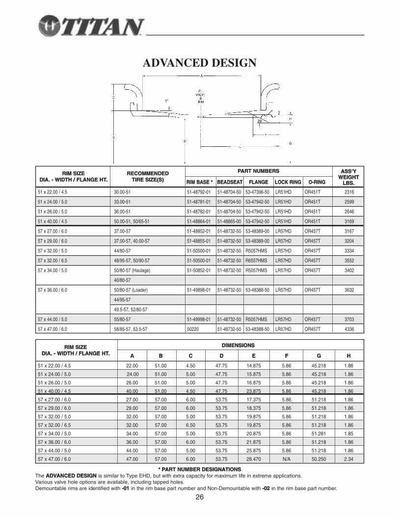
ADVANCED DESIGN
PPAARRTT NNUUMMBBEERRSS
RRIIMM BBAASSEE ** BBEEAADDSSEEAATT FFLLAANNGGEE LLOOCCKK RRIINNGG OO--RRIINNGG
51 x 22.00 / 4.5 30.00-51 51-48792-01 51-48704-50 53-47396-50 LR51HD OR451T 2316
51 x 24.00 / 5.0 33.00-51 51-48781-01 51-48704-50 53-47942-50 LR51HD OR451T 2599
51 x 26.00 / 5.0 36.00-51 51-48782-01 51-48704-50 53-47942-50 LR51HD OR451T 2646
51 x 40.00 / 4.5 50.00-51, 50/65-51 51-48864-01 51-48865-00 53-47942-50 LR51HD OR451T 3169
57 x 27.00 / 6.0 37.00-57 51-48852-01 51-48732-50 53-48389-00 LR57HD OR457T 3167
57 x 29.00 / 6.0 37.00-57, 40.00-57 51-48855-01 51-48732-50 53-48389-00 LR57HD OR457T 3204
57 x 32.00 / 5.0 44/80-57 51-50500-01 51-48732-50 R5057HMS LR57HD OR457T 3334
57 x 32.00 / 6.5 48/95-57, 50/90-57 51-50500-01 51-48732-50 R6557HMS LR57HD OR457T 3552
57 x 34.00 / 5.0 50/80-57 (Haulage) 51-50852-01 51-48732-50 R5057HMS LR57HD OR457T 3402
40/80-57
57 x 36.00 / 6.0 50/80-57 (Loader) 51-49898-01 51-48732-50 53-48388-50 LR57HD OR457T 3632
44/95-57
49.5-57, 52/80-57
57 x 44.00 / 5.0 55/80-57 51-49998-01 51-48732-50 R5057HMS LR57HD OR457T 3703
57 x 47.00 / 6.0 58/85-57, 53.5-57 50220 51-48732-50 53-48388-50 LR57HD OR457T 4336
** PPAARRTT NNUUMMBBEERR DDEESSIIGGNNAATTIIOONNSSThe AADDVVAANNCCEEDD DDEESSIIGGNN is similar to Type EHD, but with extra capacity for maximum life in extreme applications.Various valve hole options are available, including tapped holes.Demountable rims are identified with --0011 in the rim base part number and Non-Demountable with --0022 in the rim base part number.
RRIIMM SSIIZZEEDDIIAA.. -- WWIIDDTTHH // FFLLAANNGGEE HHTT..
RREECCOOMMMMEENNDDEEDDTTIIRREE SSIIZZEE((SS))
AASSSS’’YYWWEEIIGGHHTT
LLBBSS..
DDIIMMEENNSSIIOONNSS
AA BB CC DD EE FF GG HH
51 x 22.00 / 4.5 22.00 51.00 4.50 47.75 14.875 5.86 45.218 1.86
51 x 24.00 / 5.0 24.00 51.00 5.00 47.75 15.875 5.86 45.218 1.86
51 x 26.00 / 5.0 26.00 51.00 5.00 47.75 16.875 5.86 45.218 1.86
51 x 40.00 / 4.5 40.00 51.00 4.50 47.75 23.875 5.86 45.218 1.86
57 x 27.00 / 6.0 27.00 57.00 6.00 53.75 17.375 5.86 51.218 1.86
57 x 29.00 / 6.0 29.00 57.00 6.00 53.75 18.375 5.86 51.218 1.86
57 x 32.00 / 5.0 32.00 57.00 5.00 53.75 19.875 5.86 51.218 1.86
57 x 32.00 / 6.5 32.00 57.00 6.50 53.75 19.875 5.86 51.218 1.86
57 x 34.00 / 5.0 34.00 57.00 5.00 53.75 20.875 5.86 51.281 1.85
57 x 36.00 / 6.0 36.00 57.00 6.00 53.75 21.875 5.86 51.218 1.86
57 x 44.00 / 5.0 44.00 57.00 5.00 53.75 25.875 5.86 51.218 1.86
57 x 47.00 / 6.0 47.00 57.00 6.00 53.75 28.470 N/A 50.250 2.34
RRIIMM SSIIZZEEDDIIAA.. -- WWIIDDTTHH // FFLLAANNGGEE HHTT..
27
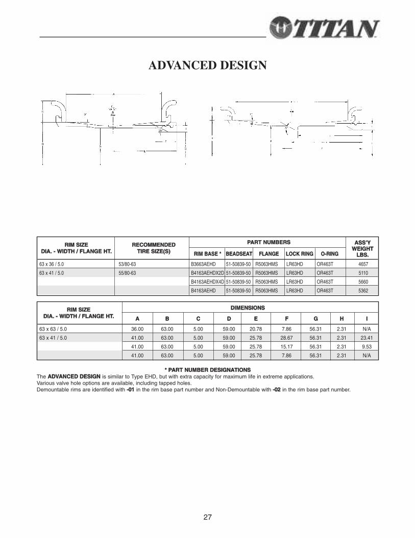
** PPAARRTT NNUUMMBBEERR DDEESSIIGGNNAATTIIOONNSSThe AADDVVAANNCCEEDD DDEESSIIGGNN is similar to Type EHD, but with extra capacity for maximum life in extreme applications.Various valve hole options are available, including tapped holes.Demountable rims are identified with --0011 in the rim base part number and Non-Demountable with --0022 in the rim base part number.
PPAARRTT NNUUMMBBEERRSS
RRIIMM BBAASSEE ** BBEEAADDSSEEAATT FFLLAANNGGEE LLOOCCKK RRIINNGG OO--RRIINNGG
63 x 36 / 5.0 53/80-63 B3663AEHD 51-50839-50 R5063HMS LR63HD OR463T 4657
63 x 41 / 5.0 55/80-63 B4163AEHDX2D 51-50839-50 R5063HMS LR63HD OR463T 5110
B4163AEHDX4D 51-50839-50 R5063HMS LR63HD OR463T 5660
B4163AEHD 51-50839-50 R5063HMS LR63HD OR463T 5362
RRIIMM SSIIZZEEDDIIAA.. -- WWIIDDTTHH // FFLLAANNGGEE HHTT..
RREECCOOMMMMEENNDDEEDDTTIIRREE SSIIZZEE((SS))
AASSSS’’YYWWEEIIGGHHTT
LLBBSS..
DDIIMMEENNSSIIOONNSS
AA BB CC DD EE FF GG HH II
63 x 63 / 5.0 36.00 63.00 5.00 59.00 20.78 7.86 56.31 2.31 N/A
63 x 41 / 5.0 41.00 63.00 5.00 59.00 25.78 28.67 56.31 2.31 23.41
41.00 63.00 5.00 59.00 25.78 15.17 56.31 2.31 9.53
41.00 63.00 5.00 59.00 25.78 7.86 56.31 2.31 N/A
RRIIMM SSIIZZEEDDIIAA.. -- WWIIDDTTHH // FFLLAANNGGEE HHTT..
ADVANCED DESIGN
28
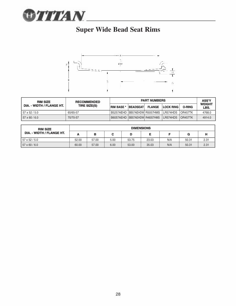
Super Wide Bead Seat Rims
PPAARRTT NNUUMMBBEERRSS
RRIIMM BBAASSEE ** BBEEAADDSSEEAATT FFLLAANNGGEE LLOOCCKK RRIINNGG OO--RRIINNGG
57 x 52 / 5.0 65/65-57 B5257AEHD BB57AEHDW R5057HMS LR574HDS OR457TK 4768.0
57 x 60 / 6.0 70/70-57 B6057AEHD BB57AEHDW R46057HMS LR574HDS OR457TK 4914.0
RRIIMM SSIIZZEEDDIIAA.. -- WWIIDDTTHH // FFLLAANNGGEE HHTT..
RREECCOOMMMMEENNDDEEDDTTIIRREE SSIIZZEE((SS))
AASSSS’’YYWWEEIIGGHHTT
LLBBSS..
DDIIMMEENNSSIIOONNSS
AA BB CC DD EE FF GG HH
57 x 52 / 5.0 52.00 57.00 5.00 53.75 23.03 N/A 50.31 2.31
57 x 60 / 6.0 60.00 57.00 6.00 53.00 35.03 N/A 50.31 2.31
RRIIMM SSIIZZEEDDIIAA.. -- WWIIDDTTHH // FFLLAANNGGEE HHTT..
29
SS PP EE CC II AA LL SS EE RR VV II CC EE RR II MM SS
30
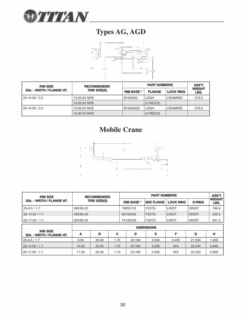
Types AG, AGD
Mobile Crane
PPAARRTT NNUUMMBBEERRSS
RRIIMM BBAASSEE ** FFLLAANNGGEE LLOOCCKK RRIINNGG
24-10.00 / 2.0 13.00-24 NHS B1024AG L2024 LR24MWG 215.5
14.00-24 NHS (2 REQ’D)
24-10.00 / 2.0 13.00-24 NHS B1024AGD L2024 LR24MWG 216.0
14.00-24 NHS (2 REQ’D)
RRIIMM SSIIZZEEDDIIAA.. -- WWIIDDTTHH // FFLLAANNGGEE HHTT..
RREECCOOMMMMEENNDDEEDDTTIIRREE SSIIZZEE((SS))
AASSSS’’YYWWEEIIGGHHTT
LLBBSS..
DDIIMMEENNSSIIOONNSS
AA BB CC DD EE FF GG HH
25-9.5 / 1.7 9.50 25.00 1.70 23.180 5.930 3.420 21.530 1.200
25-14.00 / 1.7 14.00 25.00 1.70 23.180 5.930 N/A 22.244 0.846
25-17.00 / 1.7 17.00 25.00 1.70 23.180 5.930 N/A 22.320 0.803
RRIIMM SSIIZZEEDDIIAA.. -- WWIIDDTTHH // FFLLAANNGGEE HHTT..
PPAARRTT NNUUMMBBEERRSS
RRIIMM BBAASSEE ** SSIIDDEE FFLLAANNGGEE LLOOCCKK RRIINNGG OO--RRIINNGG
25-9.5 / 1.7 385/95-25 78055118 F25TG LR25T OR25T 196.8
25-14.00 / 1.7 445/80-25 83105045 F25TG LR25T OR25T 235.6
25-17.00 / 1.7 525/80-25 74105039 F25TG LR25T OR25T 261.3
RRIIMM SSIIZZEEDDIIAA.. -- WWIIDDTTHH // FFLLAANNGGEE HHTT..
RREECCOOMMMMEENNDDEEDDTTIIRREE SSIIZZEE((SS))
AASSSS’’YYWWEEIIGGHHTT
LLBBSS..
31
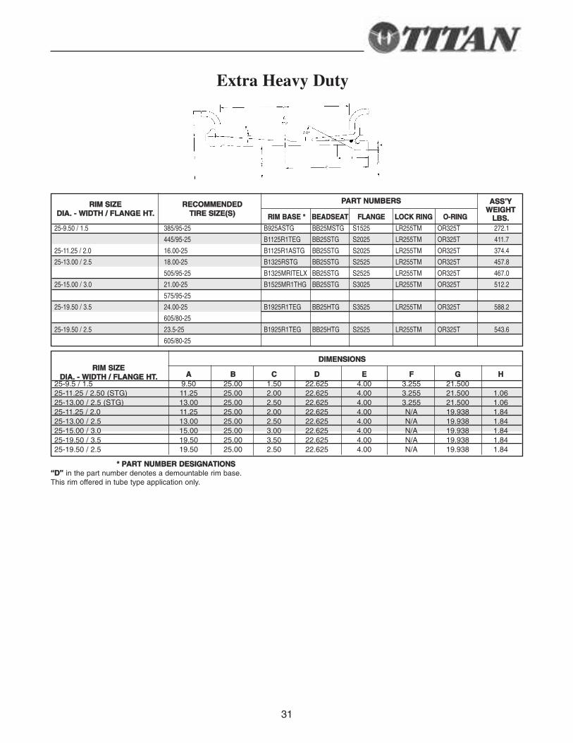
Extra Heavy Duty
** PPAARRTT NNUUMMBBEERR DDEESSIIGGNNAATTIIOONNSS““DD”” in the part number denotes a demountable rim base.This rim offered in tube type application only.
DDIIMMEENNSSIIOONNSS
AA BB CC DD EE FF GG HH25-9.5 / 1.5 9.50 25.00 1.50 22.625 4.00 3.255 21.50025-11.25 / 2.50 (STG) 11.25 25.00 2.00 22.625 4.00 3.255 21.500 1.0625-13.00 / 2.5 (STG) 13.00 25.00 2.50 22.625 4.00 3.255 21.500 1.0625-11.25 / 2.0 11.25 25.00 2.00 22.625 4.00 N/A 19.938 1.8425-13.00 / 2.5 13.00 25.00 2.50 22.625 4.00 N/A 19.938 1.8425-15.00 / 3.0 15.00 25.00 3.00 22.625 4.00 N/A 19.938 1.8425-19.50 / 3.5 19.50 25.00 3.50 22.625 4.00 N/A 19.938 1.8425-19.50 / 2.5 19.50 25.00 2.50 22.625 4.00 N/A 19.938 1.84
RRIIMM SSIIZZEEDDIIAA.. -- WWIIDDTTHH // FFLLAANNGGEE HHTT..
PPAARRTT NNUUMMBBEERRSS
RRIIMM BBAASSEE ** BBEEAADDSSEEAATT FFLLAANNGGEE LLOOCCKK RRIINNGG OO--RRIINNGG
25-9.50 / 1.5 385/95-25 B925ASTG BB25MSTG S1525 LR255TM OR325T 272.1
445/95-25 B1125R1TEG BB25STG S2025 LR255TM OR325T 411.7
25-11.25 / 2.0 16.00-25 B1125R1ASTG BB25STG S2025 LR255TM OR325T 374.4
25-13.00 / 2.5 18.00-25 B1325RSTG BB25STG S2525 LR255TM OR325T 457.8
505/95-25 B1325MRITELX BB25STG S2525 LR255TM OR325T 467.0
25-15.00 / 3.0 21.00-25 B1525MR1THG BB25STG S3025 LR255TM OR325T 512.2
575/95-25
25-19.50 / 3.5 24.00-25 B1925R1TEG BB25HTG S3525 LR255TM OR325T 588.2
605/80-25
25-19.50 / 2.5 23.5-25 B1925R1TEG BB25HTG S2525 LR255TM OR325T 543.6
605/80-25
RRIIMM SSIIZZEEDDIIAA.. -- WWIIDDTTHH // FFLLAANNGGEE HHTT..
RREECCOOMMMMEENNDDEEDDTTIIRREE SSIIZZEE((SS))
AASSSS’’YYWWEEIIGGHHTT
LLBBSS..
32** Call for part number
DDIIMMEENNSSIIOONNSS
AA BB CC DD EE FF GG
TTYYPPEE 11
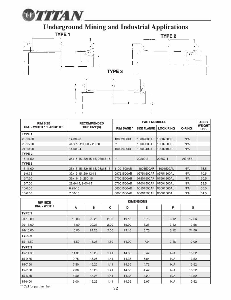
20-10.00 10.00 20.25 2.00 19.16 5.75 3.12 17.56
20-15.00 15.00 20.25 2.00 19.00 8.25 3.12 17.56
24-10.00 10.00 24.25 2.00 23.16 5.75 3.12 21.56
TTYYPPEE 22
15-11.50 11.50 15.25 1.50 14.00 7.9 3.16 13.00
TTYYPPEE 33
15-11.00 11.00 15.25 1.41 14.35 6.47 N/A 13.52
15-9.75 9.75 15.25 1.41 14.35 5.84 N/A 13.52
15-7.50 7.50 15.25 1.41 14.35 4.72 N/A 13.52
15-7.50 7.00 15.25 1.41 14.35 4.47 N/A 13.52
15-6.50 6.50 15.25 1.41 14.35 4.22 N/A 13.52
15-6.00 6.00 15.25 1.41 14.35 3.97 N/A 13.52
RRIIMM SSIIZZEEDDIIAA.. -- WWIIDDTTHH
PPAARRTT NNUUMMBBEERRSS
RRIIMM BBAASSEE ** SSIIDDEE FFLLAANNGGEE LLOOCCKK RRIINNGG OO--RRIINNGG
TTYYPPEE 11
20-10.00 14.00-20 10002000IB 10002000IF 10002000IL N/A
20-15.00 44 x 18-20, 50 x 20-30 ** 10002000iF 10002000IF N/A
24-10.00 14.00-24 10002400IB 10002400IF 10002400IF N/A
TTYYPPEE 22
15-11.50 35x15-15, 32x15-15, 28x13-15 ** 22200-2 20857-1 AS-457
TTYYPPEE 33
15-11.00 35x15-15, 32x15-15, 28x13-15 11001500AB 11001500AF 11001500AL N/A 75.5
15-9.75 32x12-15, 28x12-15 09751500AB 09751500AF 09751500AL N/A 70.5
15-7.50 36x11-15, 250-15 07001500AB 07501500AF 07501500AL N/A 60.5
15-7.00 28x9-15, 9.00-15 07001500AB 07001500AF 07001500AL N/A 58.5
15-6.50 8.25-15 06501500AB 06501500AF 06501500AL N/A 56.5
15-6.00 7.50-15 06001500AB 06001500AF 06001500AL N/A 54.5
RRIIMM SSIIZZEEDDIIAA.. -- WWIIDDTTHH // FFLLAANNGGEE HHTT..
RREECCOOMMMMEENNDDEEDDTTIIRREE SSIIZZEE((SS))
AASSSS’’YYWWEEIIGGHHTT
LLBBSS..
Underground Mining and Industrial ApplicationsTTYYPPEE 11 TTYYPPEE 22
TTYYPPEE 33
33
RR II MM // WW HH EE EE LL AA SS SS EE MM BB LL YY CC OO MM PP OO NN EE NN TT SS
3-Piece Rim Components
34
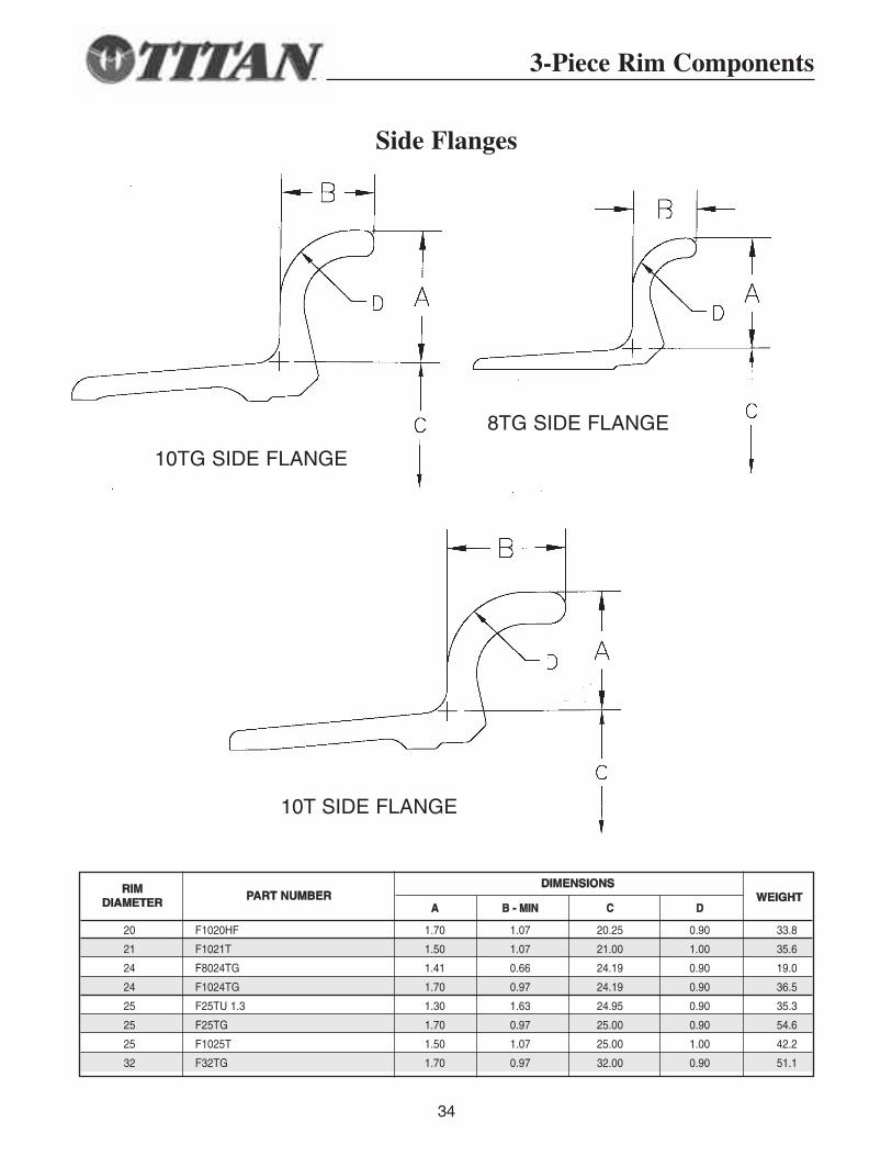
Side Flanges
DDIIMMEENNSSIIOONNSS
AA BB -- MMIINN CC DD
20 F1020HF 1.70 1.07 20.25 0.90 33.8
21 F1021T 1.50 1.07 21.00 1.00 35.6
24 F8024TG 1.41 0.66 24.19 0.90 19.0
24 F1024TG 1.70 0.97 24.19 0.90 36.5
25 F25TU 1.3 1.30 1.63 24.95 0.90 35.3
25 F25TG 1.70 0.97 25.00 0.90 54.6
25 F1025T 1.50 1.07 25.00 1.00 42.2
32 F32TG 1.70 0.97 32.00 0.90 51.1
RRIIMMDDIIAAMMEETTEERR
PPAARRTT NNUUMMBBEERR WWEEIIGGHHTT
10TG SIDE FLANGE
8TG SIDE FLANGE
10T SIDE FLANGE
35
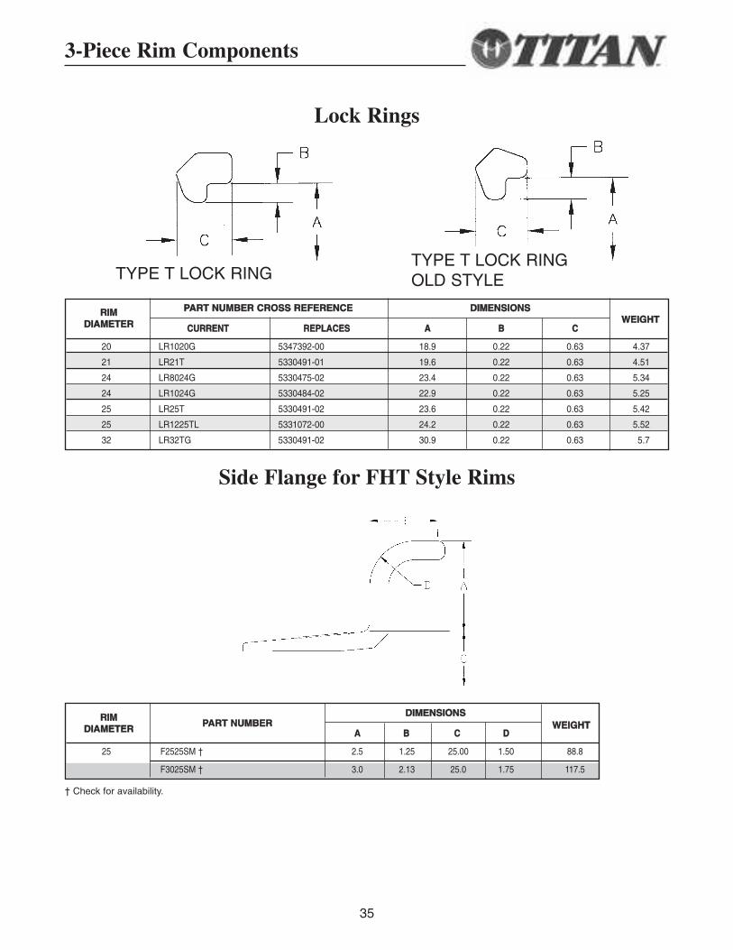
Lock Rings
Side Flange for FHT Style Rims
PPAARRTT NNUUMMBBEERR CCRROOSSSS RREEFFEERREENNCCEE DDIIMMEENNSSIIOONNSS
CCUURRRREENNTT RREEPPLLAACCEESS AA BB CC
20 LR1020G 5347392-00 18.9 0.22 0.63 4.37
21 LR21T 5330491-01 19.6 0.22 0.63 4.51
24 LR8024G 5330475-02 23.4 0.22 0.63 5.34
24 LR1024G 5330484-02 22.9 0.22 0.63 5.25
25 LR25T 5330491-02 23.6 0.22 0.63 5.42
25 LR1225TL 5331072-00 24.2 0.22 0.63 5.52
32 LR32TG 5330491-02 30.9 0.22 0.63 5.7
RRIIMMDDIIAAMMEETTEERR WWEEIIGGHHTT
3-Piece Rim Components
DDIIMMEENNSSIIOONNSS
AA BB CC DD
25 F2525SM † 2.5 1.25 25.00 1.50 88.8
F3025SM † 3.0 2.13 25.0 1.75 117.5
RRIIMMDDIIAAMMEETTEERR
PPAARRTT NNUUMMBBEERR WWEEIIGGHHTT
† Check for availability.
TYPE T LOCK RINGTYPE T LOCK RINGOLD STYLE
36
B
B
AD
C
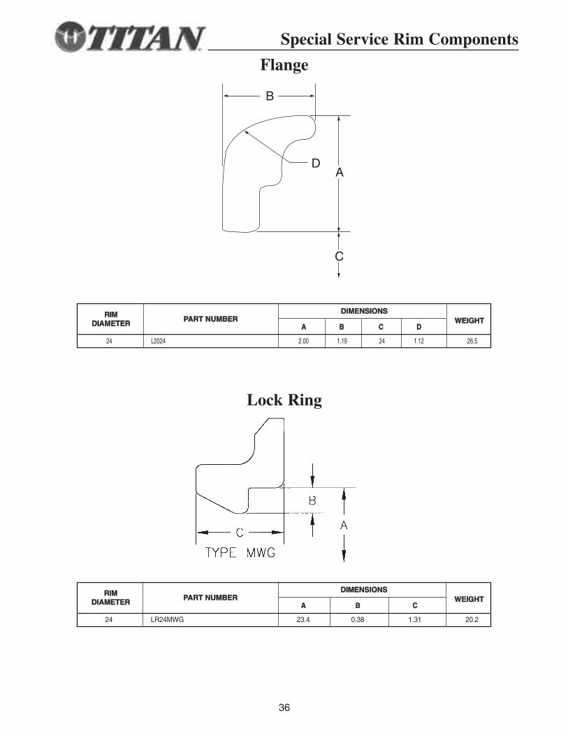
DDIIMMEENNSSIIOONNSS
AA BB CC
24 LR24MWG 23.4 0.38 1.31 20.2
RRIIMMDDIIAAMMEETTEERR
PPAARRTT NNUUMMBBEERR WWEEIIGGHHTT
DDIIMMEENNSSIIOONNSS
AA BB CC DD
24 L2024 2.00 1.19 24 1.12 26.5
RRIIMMDDIIAAMMEETTEERR
PPAARRTT NNUUMMBBEERR WWEEIIGGHHTT
Special Service Rim Components
Flange
Lock Ring
37
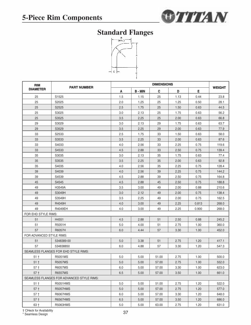
Standard Flanges
DDIIMMEENNSSIIOONNSS
AA BB -- MMIINN CC DD EE
25 S1525 1.5 1.15 25 1.13 0.44 23.8
25 S2025 2.0 1.25 25 1.25 0.50 28.1
25 S2525 2.5 1.75 25 1.50 0.63 44.5
25 S3025 3.0 2.13 25 1.75 0.63 56.2
25 S3525 3.5 2.25 25 2.00 0.63 66.8
29 S3029 3.0 2.13 29 1.75 0.63 63.7
29 S3529 3.5 2.25 29 2.00 0.63 77.9
33 S2533 2.5 1.75 33 1.50 0.63 58.0
33 S3533 3.5 2.25 33 2.00 0.63 87.6
33 S4033 4.0 2.56 33 2.25 0.75 119.6
33 S4533 4.5 2.88 33 2.50 0.75 139.4
35 S3035 3.0 2.13 35 1.75 0.63 77.4
35 S3535 3.5 2.25 35 2.00 0.63 92.8
35 S4035 4.0 2.56 35 2.25 0.75 128.4
39 S4039 4.0 2.56 39 2.25 0.75 144.2
39 S4539 4.5 2.88 39 2.50 0.75 164.8
45 S4545 4.5 2.88 45 2.50 0.75 188.8
49 H3549A 3.5 3.00 49 2.00 0.88 210.6
49 S3049H 3.0 2.12 49 2.00 0.75 138.4
49 S3549H 3.5 2.25 49 2.00 0.75 162.5
49 R4049H 4.0 3.00 49 2.25 0.813 268.0
49 R4049EH 4.0 3.00 49 2.25 0.900 268.0
FOR EHD STYLE RIMS:
51 H4551 4.5 2.88 51 2.50 0.88 245.2
51 R5051H 5.0 4.00 51 2.75 1.00 360.0
57 R6057H 6.0 4.44 57 3.30 1.00 452.0
FOR ADVANCED STYLE RIMS:
51 5348389-00 5.0 3.38 51 2.75 1.20 417.1
57 534838850 6.0 4.88 57 3.30 1.20 547.3
SEAMLESS FLANGES FOR EHD STYLE RIMS:
51 † R5051MS 5.0 5.00 51.00 2.75 1.00 500.0
51 † R5057MS 5.0 5.00 57.00 2.75 1.00 552.0
57 † R6057MS 6.0 5.00 57.00 3.30 1.00 623.0
57 † R6557MS 6.5 5.00 57.00 3.50 1.00 661.0
SEAMLESS FLANGES FOR ADVANCED STYLE RIMS:
51 † R5051HMS 5.0 5.00 51.00 2.75 1.20 522.0
57 † R5057HMS 5.0 5.00 57.00 2.75 1.20 577.0
57 † R6067HMS 6.0 5.00 57.00 3.30 1.20 648.0
57 † R6567HMS 6.5 5.00 57.00 3.50 1.20 686.0
63 † R5063HMS 5.0 5.00 63.00 2.75 1.20 631.0
RRIIMMDDIIAAMMEETTEERR PPAARRTT NNUUMMBBEERR WWEEIIGGHHTT
5-Piece Rim Components
† CHeck for Availability* Seamless Design
38
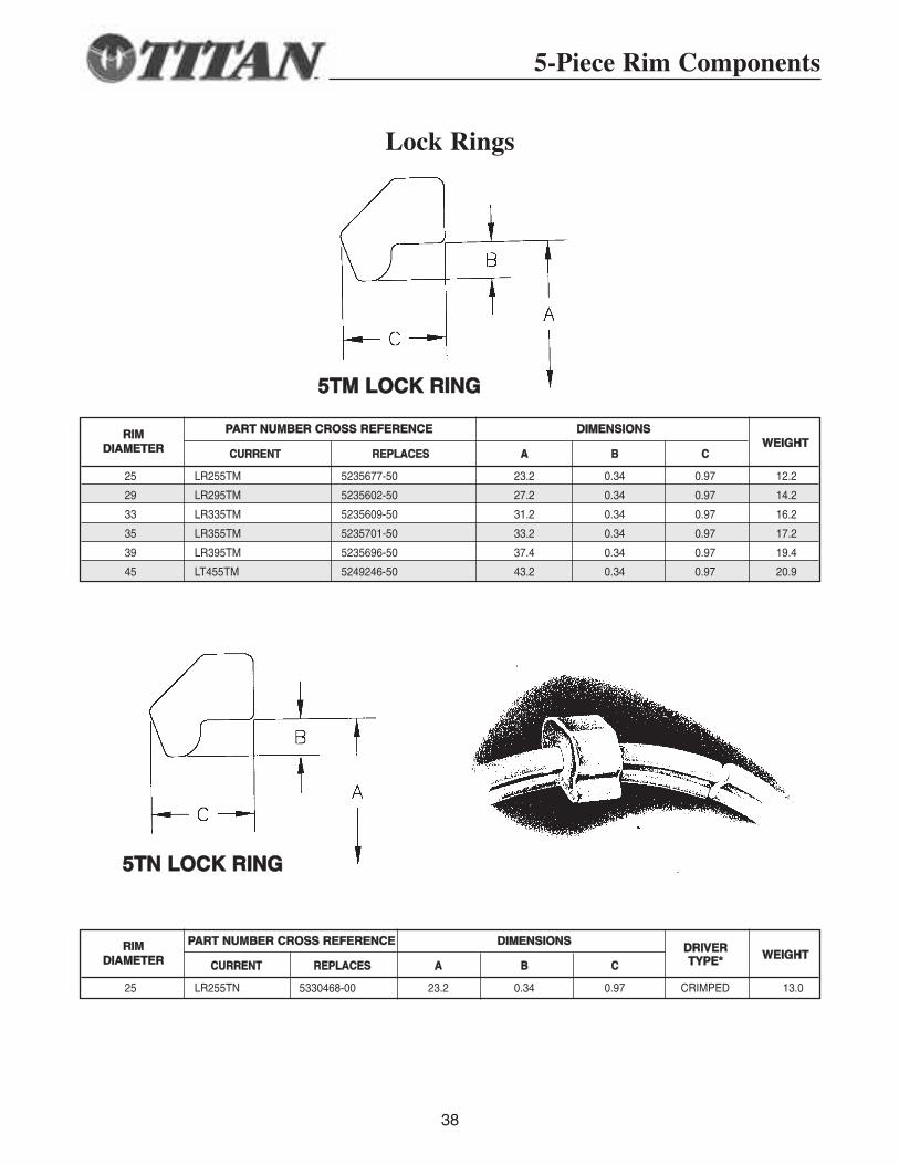
Lock Rings
PPAARRTT NNUUMMBBEERR CCRROOSSSS RREEFFEERREENNCCEE DDIIMMEENNSSIIOONNSS
CCUURRRREENNTT RREEPPLLAACCEESS AA BB CC
25 LR255TM 5235677-50 23.2 0.34 0.97 12.2
29 LR295TM 5235602-50 27.2 0.34 0.97 14.2
33 LR335TM 5235609-50 31.2 0.34 0.97 16.2
35 LR355TM 5235701-50 33.2 0.34 0.97 17.2
39 LR395TM 5235696-50 37.4 0.34 0.97 19.4
45 LT455TM 5249246-50 43.2 0.34 0.97 20.9
RRIIMMDDIIAAMMEETTEERR WWEEIIGGHHTT
PPAARRTT NNUUMMBBEERR CCRROOSSSS RREEFFEERREENNCCEE DDIIMMEENNSSIIOONNSS
CCUURRRREENNTT RREEPPLLAACCEESS AA BB CC
25 LR255TN 5330468-00 23.2 0.34 0.97 CRIMPED 13.0
RRIIMMDDIIAAMMEETTEERR WWEEIIGGHHTT
DDRRIIVVEERRTTYYPPEE**
55TTMM LLOOCCKK RRIINNGG
55TTNN LLOOCCKK RRIINNGG
5-Piece Rim Components
39
5-Piece Rim Components
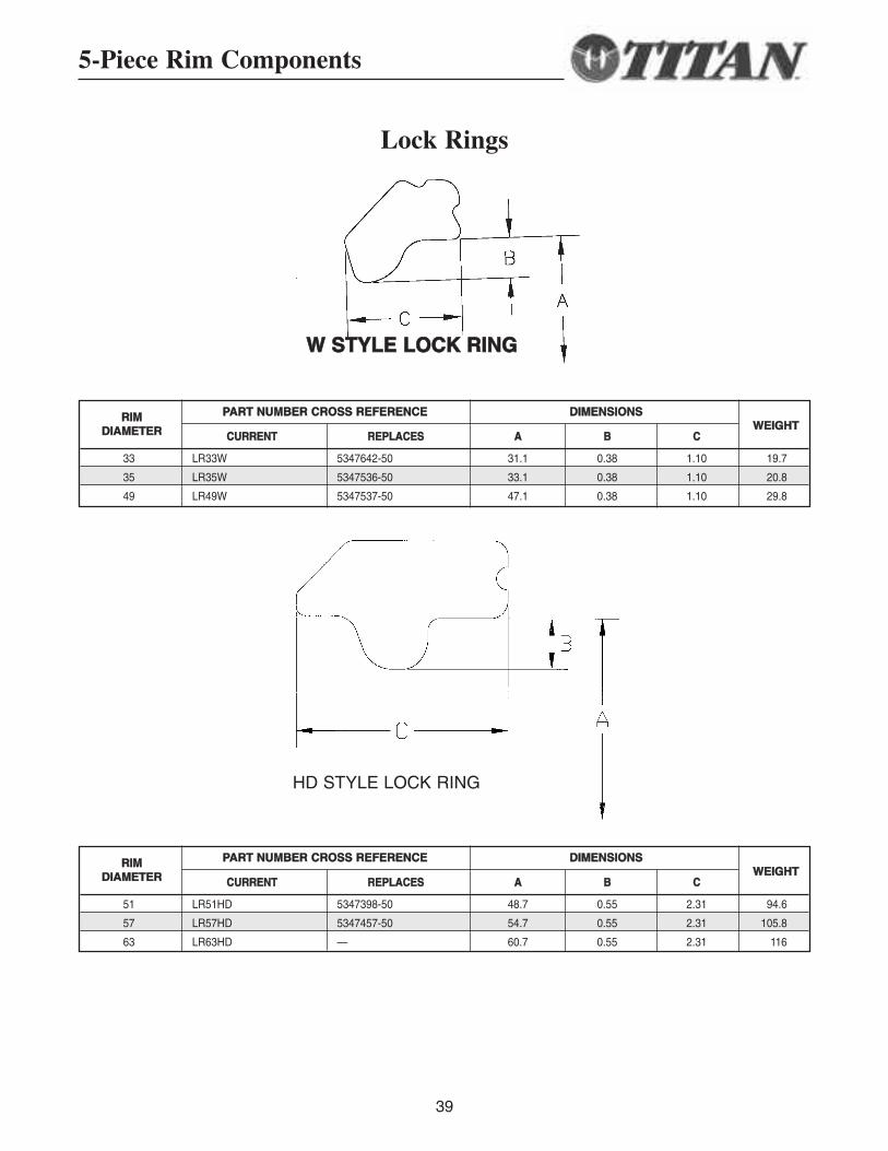
Lock Rings
PPAARRTT NNUUMMBBEERR CCRROOSSSS RREEFFEERREENNCCEE DDIIMMEENNSSIIOONNSS
CCUURRRREENNTT RREEPPLLAACCEESS AA BB CC
33 LR33W 5347642-50 31.1 0.38 1.10 19.7
35 LR35W 5347536-50 33.1 0.38 1.10 20.8
49 LR49W 5347537-50 47.1 0.38 1.10 29.8
RRIIMMDDIIAAMMEETTEERR WWEEIIGGHHTT
PPAARRTT NNUUMMBBEERR CCRROOSSSS RREEFFEERREENNCCEE DDIIMMEENNSSIIOONNSS
CCUURRRREENNTT RREEPPLLAACCEESS AA BB CC
51 LR51HD 5347398-50 48.7 0.55 2.31 94.6
57 LR57HD 5347457-50 54.7 0.55 2.31 105.8
63 LR63HD — 60.7 0.55 2.31 116
RRIIMMDDIIAAMMEETTEERR WWEEIIGGHHTT
HD STYLE LOCK RING
WW SSTTYYLLEE LLOOCCKK RRIINNGG
40
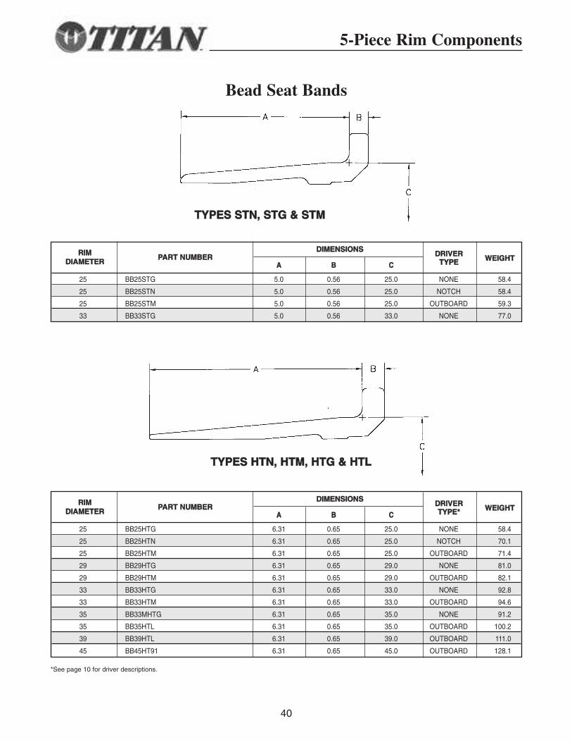
Bead Seat Bands
DDIIMMEENNSSIIOONNSS
AA BB CC
25 BB25STG 5.0 0.56 25.0 NONE 58.4
25 BB25STN 5.0 0.56 25.0 NOTCH 58.4
25 BB25STM 5.0 0.56 25.0 OUTBOARD 59.3
33 BB33STG 5.0 0.56 33.0 NONE 77.0
RRIIMMDDIIAAMMEETTEERR
PPAARRTT NNUUMMBBEERR WWEEIIGGHHTTDDRRIIVVEERR
TTYYPPEE
DDIIMMEENNSSIIOONNSS
AA BB CC
25 BB25HTG 6.31 0.65 25.0 NONE 58.4
25 BB25HTN 6.31 0.65 25.0 NOTCH 70.1
25 BB25HTM 6.31 0.65 25.0 OUTBOARD 71.4
29 BB29HTG 6.31 0.65 29.0 NONE 81.0
29 BB29HTM 6.31 0.65 29.0 OUTBOARD 82.1
33 BB33HTG 6.31 0.65 33.0 NONE 92.8
33 BB33HTM 6.31 0.65 33.0 OUTBOARD 94.6
35 BB33MHTG 6.31 0.65 35.0 NONE 91.2
35 BB35HTL 6.31 0.65 35.0 OUTBOARD 100.2
39 BB39HTL 6.31 0.65 39.0 OUTBOARD 111.0
45 BB45HT91 6.31 0.65 45.0 OUTBOARD 128.1
RRIIMMDDIIAAMMEETTEERR
PPAARRTT NNUUMMBBEERR WWEEIIGGHHTTDDRRIIVVEERRTTYYPPEE**
*See page 10 for driver descriptions.
5-Piece Rim Components
TTYYPPEESS HHTTNN,, HHTTMM,, HHTTGG && HHTTLL
TTYYPPEESS SSTTNN,, SSTTGG && SSTTMM
5-Piece Rim Components
41
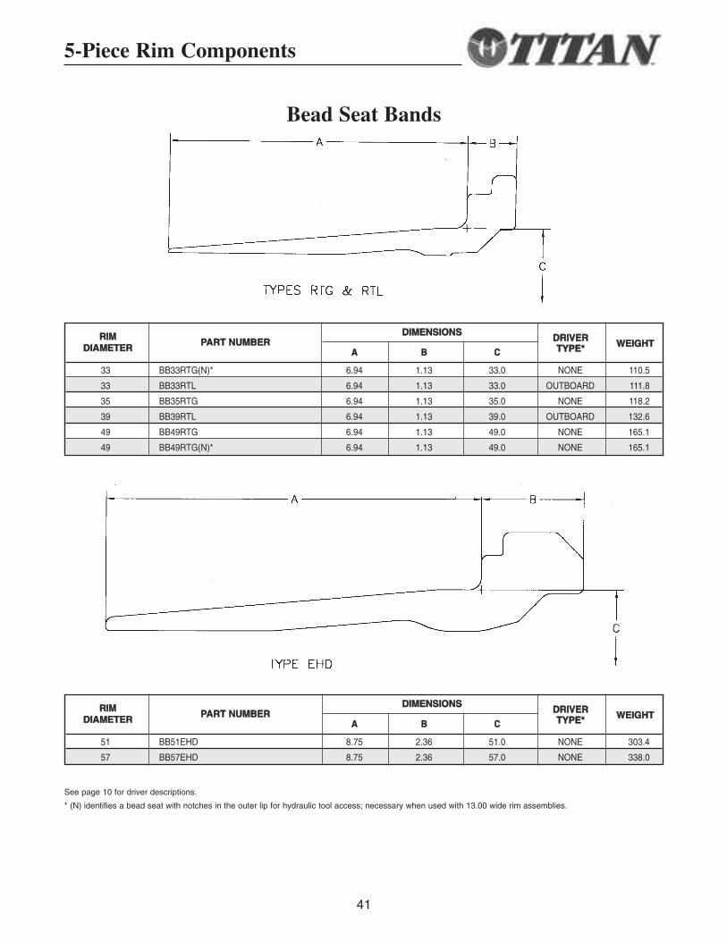
Bead Seat Bands
DDIIMMEENNSSIIOONNSS
AA BB CC
33 BB33RTG(N)* 6.94 1.13 33.0 NONE 110.5
33 BB33RTL 6.94 1.13 33.0 OUTBOARD 111.8
35 BB35RTG 6.94 1.13 35.0 NONE 118.2
39 BB39RTL 6.94 1.13 39.0 OUTBOARD 132.6
49 BB49RTG 6.94 1.13 49.0 NONE 165.1
49 BB49RTG(N)* 6.94 1.13 49.0 NONE 165.1
RRIIMMDDIIAAMMEETTEERR
PPAARRTT NNUUMMBBEERR WWEEIIGGHHTTDDRRIIVVEERRTTYYPPEE**
DDIIMMEENNSSIIOONNSS
AA BB CC
51 BB51EHD 8.75 2.36 51.0 NONE 303.4
57 BB57EHD 8.75 2.36 57.0 NONE 338.0
RRIIMMDDIIAAMMEETTEERR
PPAARRTT NNUUMMBBEERR WWEEIIGGHHTTDDRRIIVVEERRTTYYPPEE**
See page 10 for driver descriptions.
* (N) identifies a bead seat with notches in the outer lip for hydraulic tool access; necessary when used with 13.00 wide rim assemblies.
42
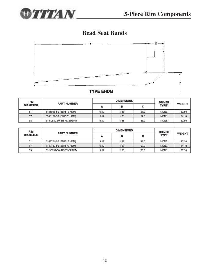
DDIIMMEENNSSIIOONNSS
AA BB CC
51 5146946-50 (BB751EHDM) 9.17 1.38 51.0 NONE 302.0
57 5348169-50 (BB757EHDM) 9.17 1.38 57.0 NONE 341.0
63 51-50839-50 (BB763EHDM) 9.17 1.38 63.0 NONE 502.0
RRIIMMDDIIAAMMEETTEERR
PPAARRTT NNUUMMBBEERR WWEEIIGGHHTTDDRRIIVVEERRTTYYPPEE**
DDIIMMEENNSSIIOONNSS
AA BB CC
51 5148704-50 (BB751EHDM) 9.17 1.38 51.0 NONE 302.0
57 5148732-50 (BB757EHDM) 9.17 1.38 57.0 NONE 341.0
63 51-50839-50 (BB763EHDM) 9.17 1.38 63.0 NONE 502.0
RRIIMMDDIIAAMMEETTEERR
PPAARRTT NNUUMMBBEERR WWEEIIGGHHTTDDRRIIVVEERRTTYYPPEE
TTYYPPEE EEHHDDMM
5-Piece Rim Components
Bead Seat Bands
43
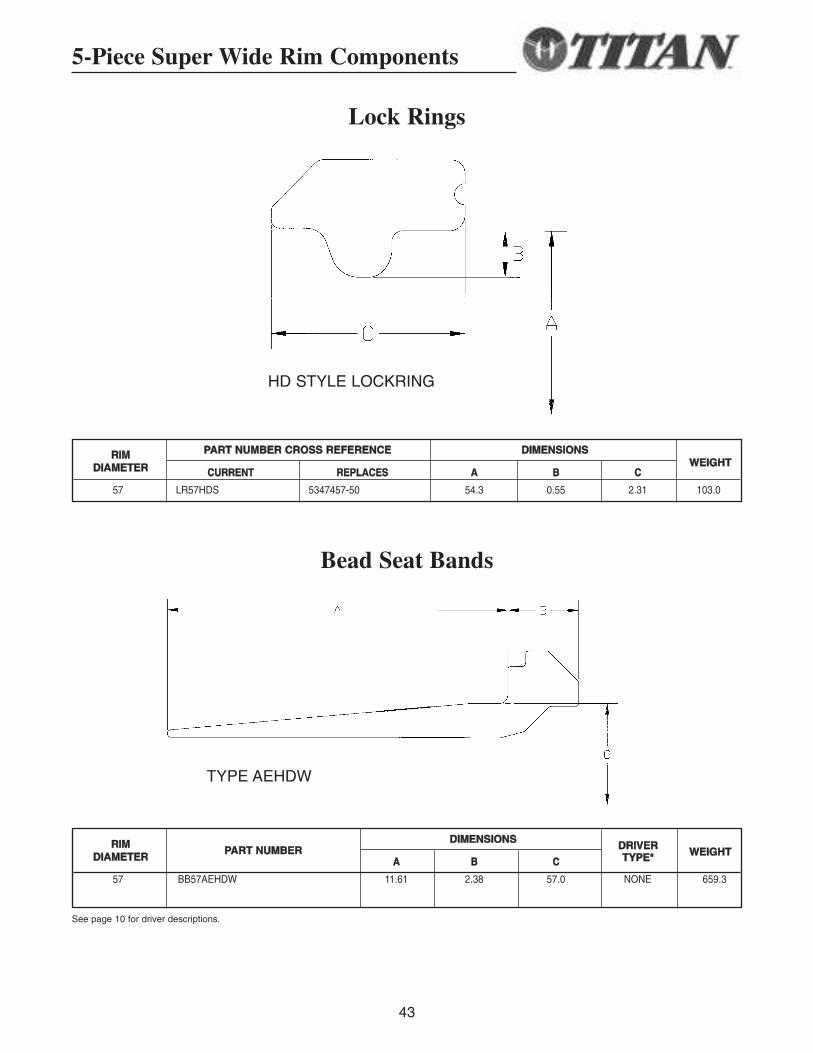
Lock Rings
5-Piece Super Wide Rim Components
Bead Seat Bands
DDIIMMEENNSSIIOONNSS
AA BB CC
57 BB57AEHDW 11.61 2.38 57.0 NONE 659.3
RRIIMMDDIIAAMMEETTEERR
PPAARRTT NNUUMMBBEERR WWEEIIGGHHTTDDRRIIVVEERRTTYYPPEE**
See page 10 for driver descriptions.
TYPE AEHDW
PPAARRTT NNUUMMBBEERR CCRROOSSSS RREEFFEERREENNCCEE DDIIMMEENNSSIIOONNSS
CCUURRRREENNTT RREEPPLLAACCEESS AA BB CC
57 LR57HDS 5347457-50 54.3 0.55 2.31 103.0
RRIIMMDDIIAAMMEETTEERR WWEEIIGGHHTT
HD STYLE LOCKRING

44
45
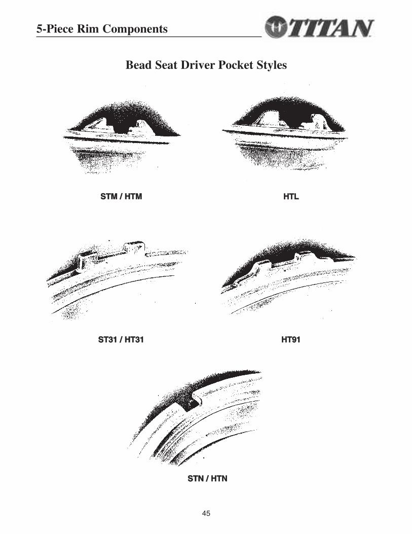
Bead Seat Driver Pocket Styles
SSTTMM // HHTTMM HHTTLL
SSTT3311 // HHTT3311 HHTT9911
SSTTNN // HHTTNN
5-Piece Rim Components
46
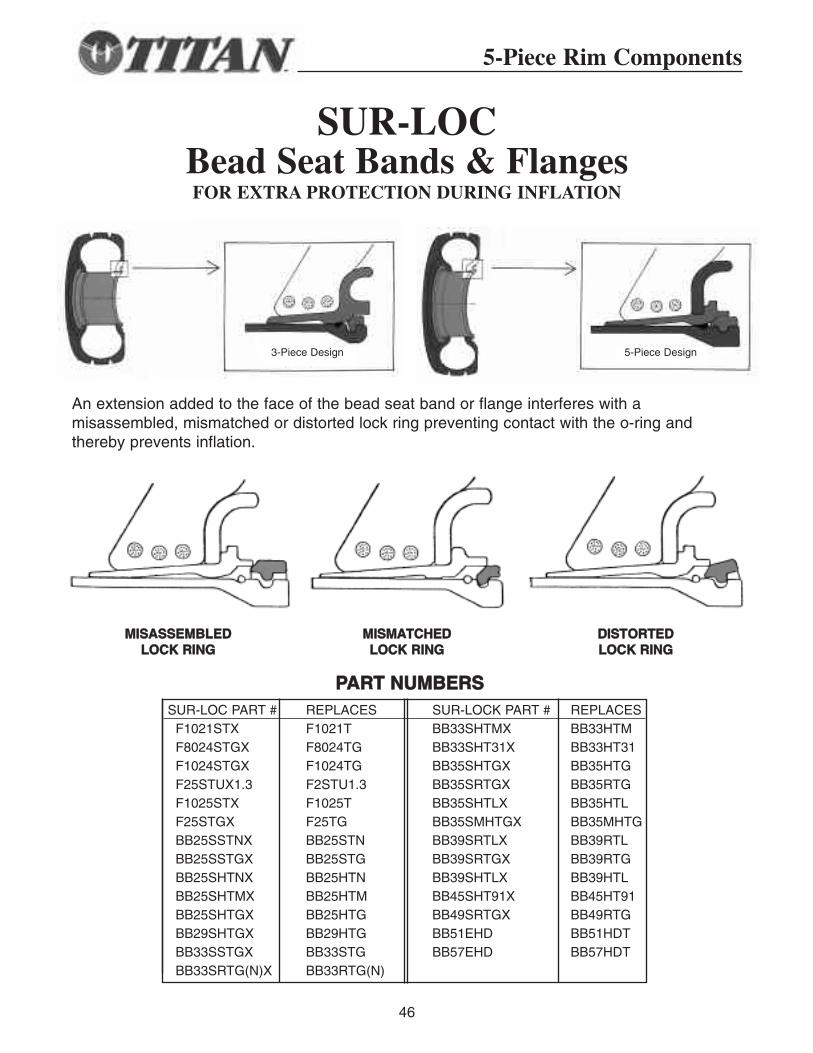
SUR-LOCBead Seat Bands & FlangesFOR EXTRA PROTECTION DURING INFLATION
SUR-LOC PART # REPLACES SUR-LOCK PART # REPLACESF1021STX F1021T BB33SHTMX BB33HTMF8024STGX F8024TG BB33SHT31X BB33HT31F1024STGX F1024TG BB35SHTGX BB35HTGF25STUX1.3 F2STU1.3 BB35SRTGX BB35RTGF1025STX F1025T BB35SHTLX BB35HTLF25STGX F25TG BB35SMHTGX BB35MHTGBB25SSTNX BB25STN BB39SRTLX BB39RTLBB25SSTGX BB25STG BB39SRTGX BB39RTGBB25SHTNX BB25HTN BB39SHTLX BB39HTLBB25SHTMX BB25HTM BB45SHT91X BB45HT91BB25SHTGX BB25HTG BB49SRTGX BB49RTGBB29SHTGX BB29HTG BB51EHD BB51HDTBB33SSTGX BB33STG BB57EHD BB57HDTBB33SRTG(N)X BB33RTG(N)
PPAARRTT NNUUMMBBEERRSS
An extension added to the face of the bead seat band or flange interferes with a misassembled, mismatched or distorted lock ring preventing contact with the o-ring and thereby prevents inflation.
MMIISSAASSSSEEMMBBLLEEDD LLOOCCKK RRIINNGG
MMIISSMMAATTCCHHEEDD LLOOCCKK RRIINNGG
DDIISSTTOORRTTEEDDLLOOCCKK RRIINNGG
5-Piece Rim Components
3-Piece Design 5-Piece Design
47
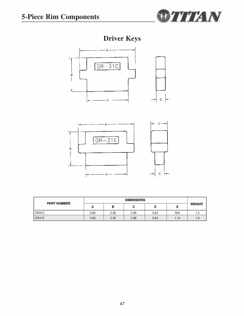
Driver Keys
DDIIMMEENNSSIIOONNSS
AA BB CC DD EE
DR31C 3.88 2.38 2.88 0.64 N/A 1.2
DR31E 3.88 2.38 2.88 0.64 1.14 1.9
PPAARRTT NNUUMMBBEERR WWEEIIGGHHTT
5-Piece Rim Components
48
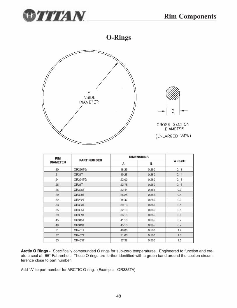
O-Rings
DDIIMMEENNSSIIOONNSS
AA BB
20 OR220TG 18.25 0.260 0.13
21 OR21T 19.25 0.260 0.14
24 OR224TG 22.00 0.260 0.15
25 OR25T 22.75 0.260 0.16
25 OR325T 22.44 0.385 0.3
29 OR329T 26.25 0.385 0.4
32 OR232T 29.062 0.260 0.2
33 OR333T 30.13 0.385 0.5
35 OR335T 32.13 0.385 0.5
39 OR339T 36.13 0.385 0.6
45 OR345T 41.13 0.385 0.7
49 OR349T 45.13 0.385 0.7
51 OR451T 46.00 0.500 1.2
57 OR457T 51.63 0.500 1.3
63 OR463T 57.32 0.500 1.5
RRIIMMDDIIAAMMEETTEERR WWEEIIGGHHTTPPAARRTT NNUUMMBBEERR
AArrccttiicc OO RRiinnggss -- Specifically compounded O rings for sub-zero temperatures. Engineered to function and cre-ate a seal at -65° Fahrenheit. These O rings are further identified with a green band around the section circum-ference close to part number.
Add “A” to part number for ARCTIC O ring. (Example - OR335TA)
Rim Components
49
Safety Information
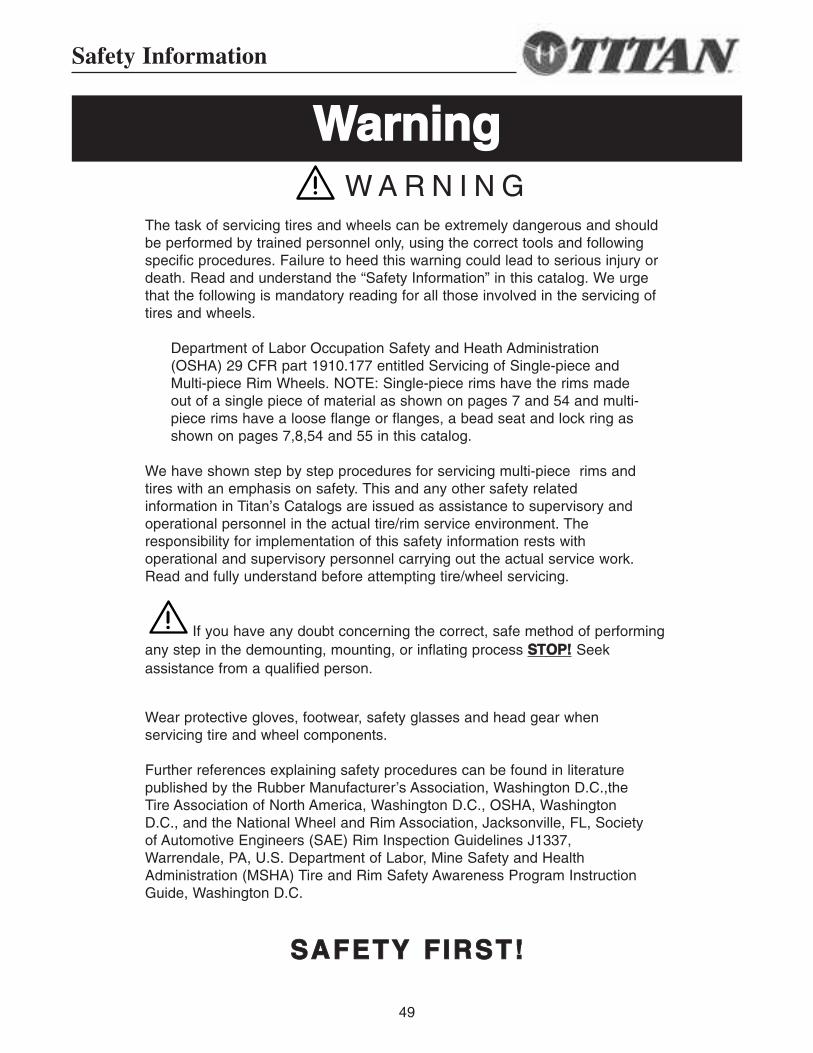
W A R N I N GThe task of servicing tires and wheels can be extremely dangerous and shouldbe performed by trained personnel only, using the correct tools and followingspecific procedures. Failure to heed this warning could lead to serious injury ordeath. Read and understand the “Safety Information” in this catalog. We urgethat the following is mandatory reading for all those involved in the servicing oftires and wheels.
Department of Labor Occupation Safety and Heath Administration(OSHA) 29 CFR part 1910.177 entitled Servicing of Single-piece andMulti-piece Rim Wheels. NOTE: Single-piece rims have the rims madeout of a single piece of material as shown on pages 7 and 54 and multi-piece rims have a loose flange or flanges, a bead seat and lock ring asshown on pages 7,8,54 and 55 in this catalog.
We have shown step by step procedures for servicing multi-piece rims andtires with an emphasis on safety. This and any other safety relatedinformation in Titan’s Catalogs are issued as assistance to supervisory andoperational personnel in the actual tire/rim service environment. Theresponsibility for implementation of this safety information rests withoperational and supervisory personnel carrying out the actual service work.Read and fully understand before attempting tire/wheel servicing.
If you have any doubt concerning the correct, safe method of performingany step in the demounting, mounting, or inflating process SSTTOOPP!! Seekassistance from a qualified person.
Wear protective gloves, footwear, safety glasses and head gear whenservicing tire and wheel components.
Further references explaining safety procedures can be found in literaturepublished by the Rubber Manufacturer’s Association, Washington D.C.,theTire Association of North America, Washington D.C., OSHA, WashingtonD.C., and the National Wheel and Rim Association, Jacksonville, FL, Societyof Automotive Engineers (SAE) Rim Inspection Guidelines J1337,Warrendale, PA, U.S. Department of Labor, Mine Safety and HealthAdministration (MSHA) Tire and Rim Safety Awareness Program InstructionGuide, Washington D.C.
SSAAFFEETTYY FFIIRRSSTT!!
WWaarrnniinngg
50
Safety Information
GGEENNEERRAALL WWAARRNNIINNGGSS
This symbol indicates a warning message.
Failure to heed warnings could lead to serious injury or death.
• The task of servicing tires and wheels can be extremely dangerous and should beperformed by trained personnel only, using the correct tools, and following the procedurespresented here and in manufacturer’s catalogs, instruction manuals, or other industry andgovernment instruction material.
• Always use approved tire and rim combinations for sizes and contours.
• Always wear personal protection equipment such as gloves, footwear, eye protection,hearing protection and head gear when servicing tire and wheel components.
• Never exceed manufacturer’s recommended tire inflation pressure.
• Always use proper lifting techniques, and mechanized lifting aids to move heavycomponents and assemblies.
• Always take care when moving tires and wheels that other people in the area are notendangered.
• Never leave a tire, wheel, or assembly unsecured in a vertical position.
• Parts that are cracked, worn, pitted with corrosion, or damaged must be destroyed,discarded, and replaced with good parts.
• Always exhaust all air from the tire prior to demounting, see page 59.
• Never try to repair wheel, rim, or tire component parts. Replace all damaged, worn, orsuspect parts with good parts.
• Never reinflate a tire that has lost air pressure or has been run flat without determining andcorrecting the problem.
• When conducting routine tire inspections also conduct a visual inspection of wheel and rimcomponents. Always correct any non-conformities.
• Always verify that part numbers and size designation of component parts are correctlymatched for the assembly. See pages 6 and 57 for part number location.
• Always place wheel and tire assemblies in restraining devices when inflating tires. See page63, item 11 and page 66, item 9.
51
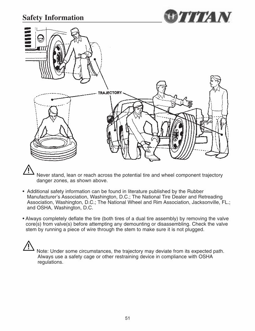
Never stand, lean or reach across the potential tire and wheel component trajectorydanger zones, as shown above.
• Additional safety information can be found in literature published by the RubberManufacturer’s Association, Washington, D.C.; The National Tire Dealer and RetreadingAssociation, Washington, D.C.; The National Wheel and Rim Association, Jacksonville, FL.;and OSHA, Washington, D.C.
• Always completely deflate the tire (both tires of a dual tire assembly) by removing the valvecore(s) from valve(s) before attempting any demounting or disassembling. Check the valvestem by running a piece of wire through the stem to make sure it is not plugged.
Note: Under some circumstances, the trajectory may deviate from its expected path. Always use a safety cage or other restraining device in compliance with OSHAregulations.
Safety Information
52
Safety Information
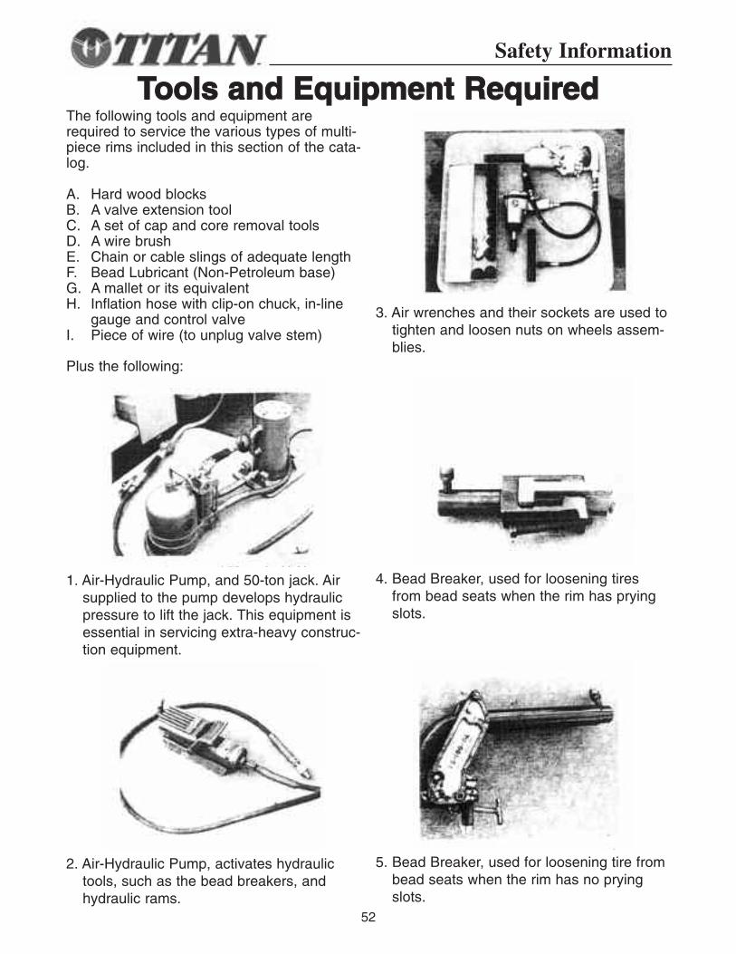
The following tools and equipment arerequired to service the various types of multi-piece rims included in this section of the cata-log.
A. Hard wood blocksB. A valve extension toolC. A set of cap and core removal toolsD. A wire brushE. Chain or cable slings of adequate lengthF. Bead Lubricant (Non-Petroleum base)G. A mallet or its equivalentH. Inflation hose with clip-on chuck, in-line
gauge and control valveI. Piece of wire (to unplug valve stem)
Plus the following:
1. Air-Hydraulic Pump, and 50-ton jack. Airsupplied to the pump develops hydraulicpressure to lift the jack. This equipment isessential in servicing extra-heavy construc-tion equipment.
2. Air-Hydraulic Pump, activates hydraulictools, such as the bead breakers, andhydraulic rams.
3. Air wrenches and their sockets are used totighten and loosen nuts on wheels assem-blies.
4. Bead Breaker, used for loosening tiresfrom bead seats when the rim has pryingslots.
5. Bead Breaker, used for loosening tire frombead seats when the rim has no pryingslots.
TToooollss aanndd EEqquuiippmmeenntt RReeqquuiirreedd
53
Safety Information
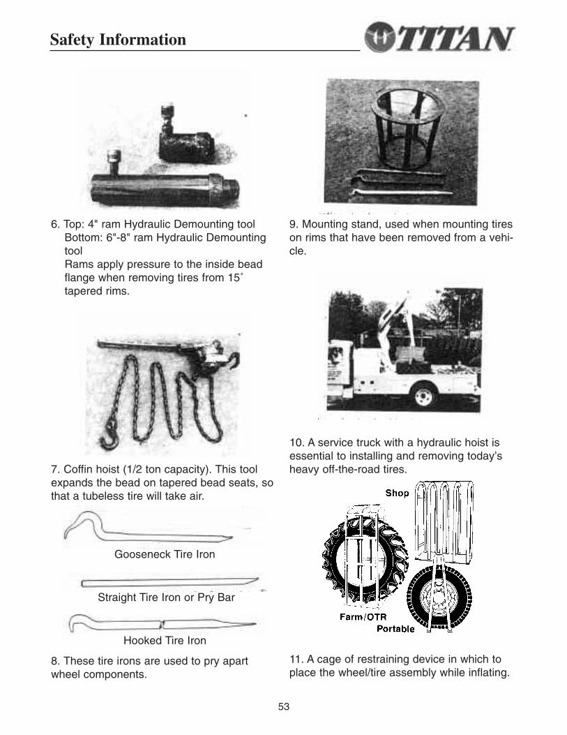
6. Top: 4" ram Hydraulic Demounting toolBottom: 6"-8" ram Hydraulic DemountingtoolRams apply pressure to the inside beadflange when removing tires from 15˚tapered rims.
7. Coffin hoist (1/2 ton capacity). This toolexpands the bead on tapered bead seats, sothat a tubeless tire will take air.
8. These tire irons are used to pry apartwheel components.
9. Mounting stand, used when mounting tireson rims that have been removed from a vehi-cle.
10. A service truck with a hydraulic hoist isessential to installing and removing today’sheavy off-the-road tires.
11. A cage of restraining device in which toplace the wheel/tire assembly while inflating.
Gooseneck Tire Iron
Straight Tire Iron or Pry Bar
Hooked Tire Iron
54
Safety Information
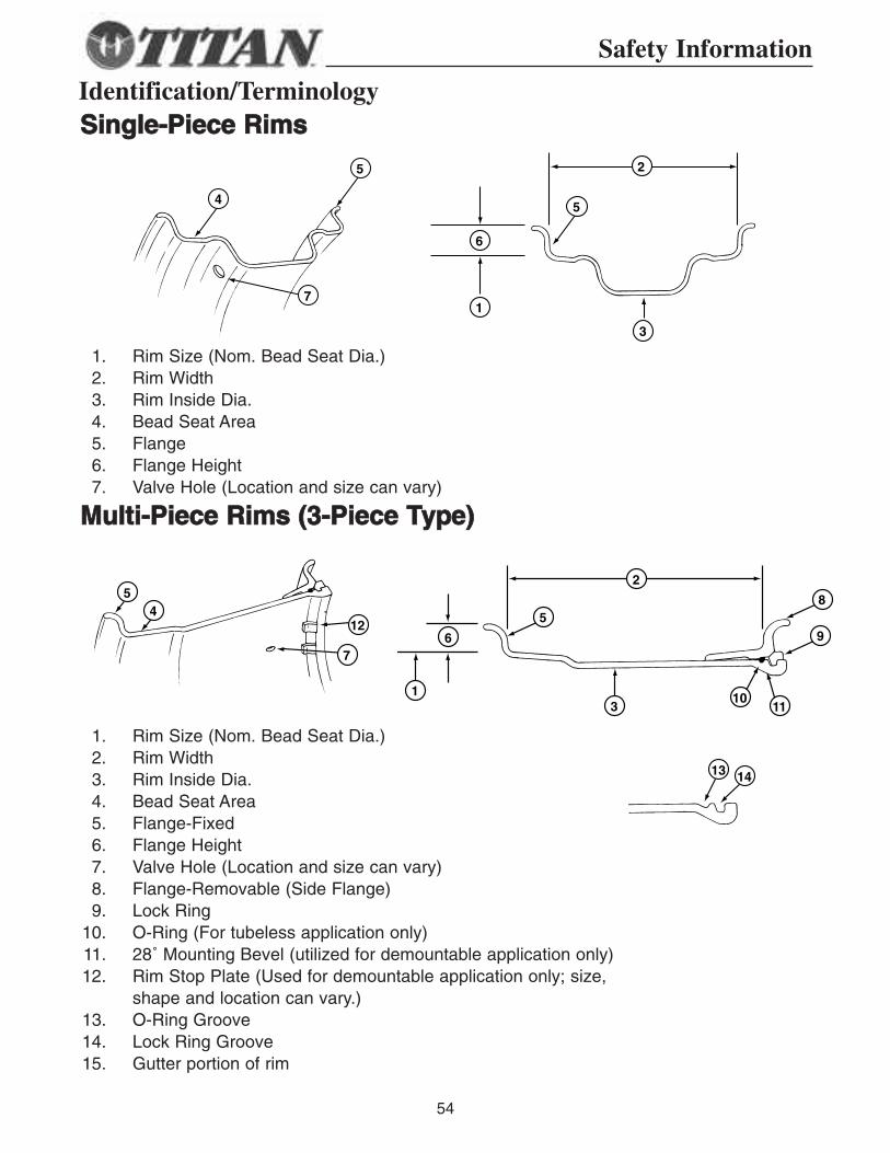
Identification/TerminologySSiinnggllee--PPiieeccee RRiimmss
1. Rim Size (Nom. Bead Seat Dia.)2. Rim Width3. Rim Inside Dia.4. Bead Seat Area5. Flange6. Flange Height7. Valve Hole (Location and size can vary)
MMuullttii--PPiieeccee RRiimmss ((33--PPiieeccee TTyyppee))
1. Rim Size (Nom. Bead Seat Dia.)2. Rim Width3. Rim Inside Dia.4. Bead Seat Area5. Flange-Fixed6. Flange Height7. Valve Hole (Location and size can vary)8. Flange-Removable (Side Flange)9. Lock Ring
10. O-Ring (For tubeless application only)11. 28˚ Mounting Bevel (utilized for demountable application only)12. Rim Stop Plate (Used for demountable application only; size,
shape and location can vary.)13. O-Ring Groove14. Lock Ring Groove15. Gutter portion of rim
4
5
6
1
5
7
3
2
5
58
96
412
7
13
1011
13 14
2
5
58
96
412
7
13
1011
13 14
2
5
58
96
412
7
13
1011
13 14
2
4
5
6
1
5
7
3
2
55
Safety Information
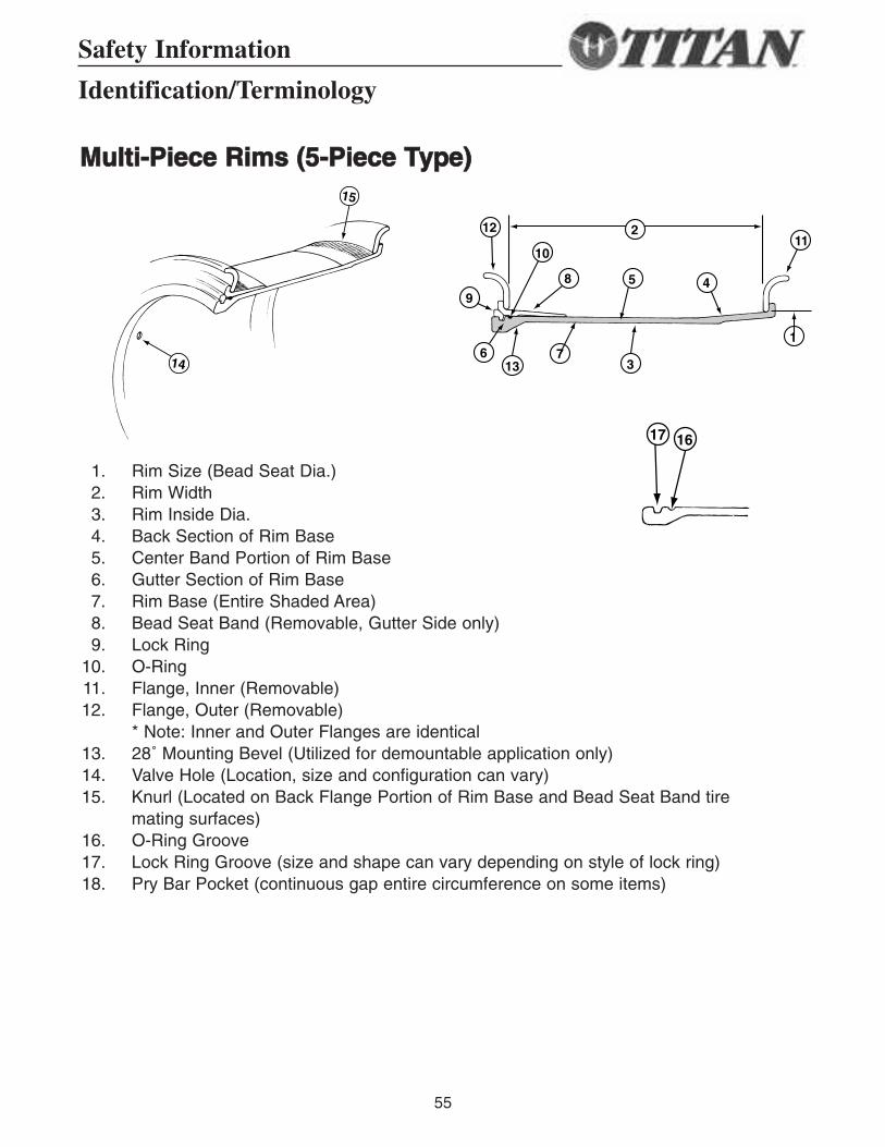
MMuullttii--PPiieeccee RRiimmss ((55--PPiieeccee TTyyppee))
1. Rim Size (Bead Seat Dia.)2. Rim Width3. Rim Inside Dia.4. Back Section of Rim Base5. Center Band Portion of Rim Base6. Gutter Section of Rim Base7. Rim Base (Entire Shaded Area)8. Bead Seat Band (Removable, Gutter Side only)9. Lock Ring
10. O-Ring11. Flange, Inner (Removable)12. Flange, Outer (Removable)
* Note: Inner and Outer Flanges are identical13. 28˚ Mounting Bevel (Utilized for demountable application only)14. Valve Hole (Location, size and configuration can vary)15. Knurl (Located on Back Flange Portion of Rim Base and Bead Seat Band tire
mating surfaces)16. O-Ring Groove17. Lock Ring Groove (size and shape can vary depending on style of lock ring)18. Pry Bar Pocket (continuous gap entire circumference on some items)
15
14
1617
5
12
9
613 7
8
10
4
11
1
2
3
15
14
1617
5
12
9
613
7
8
10
4
11
1
2
3
15
14
1617
5
12
9
613
7
8
10
4
11
1
2
3
Identification/Terminology
56
Safety Information
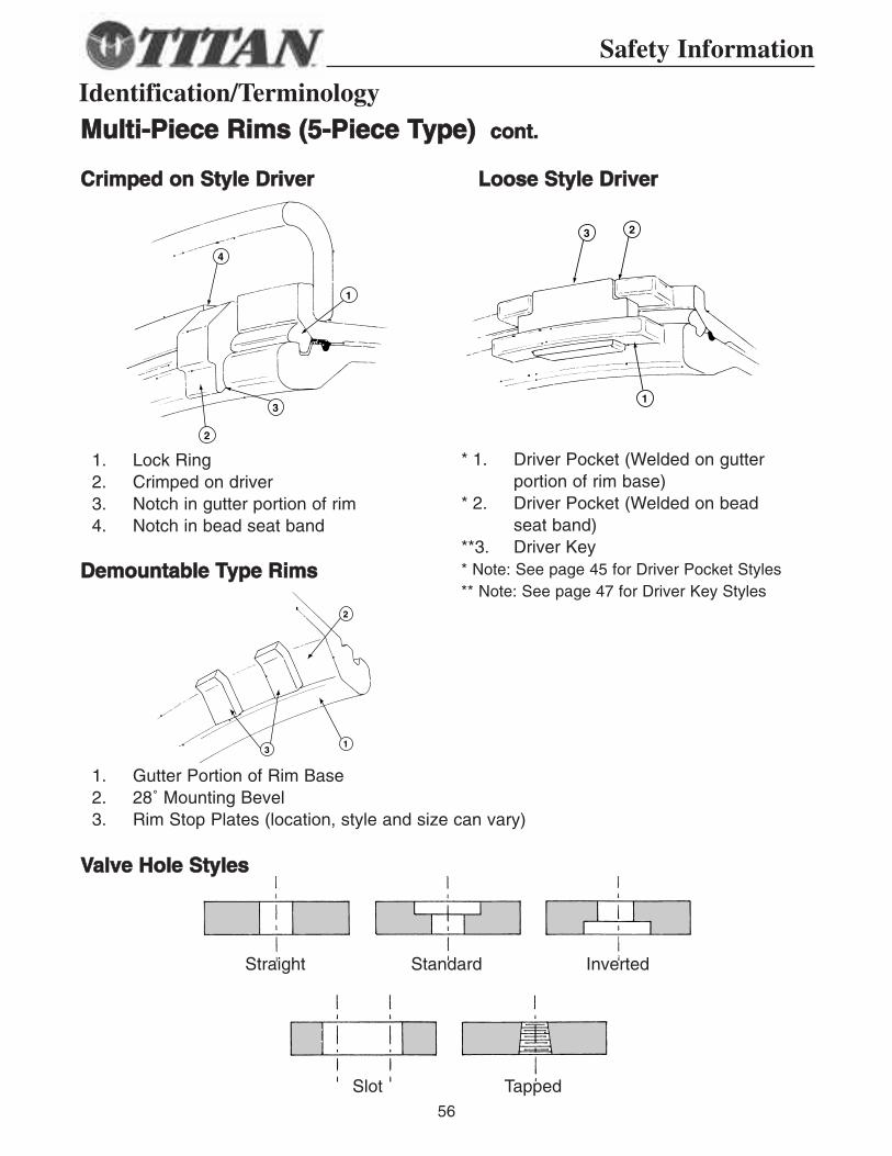
MMuullttii--PPiieeccee RRiimmss ((55--PPiieeccee TTyyppee)) ccoonntt..
1. Lock Ring2. Crimped on driver3. Notch in gutter portion of rim4. Notch in bead seat band
1. Gutter Portion of Rim Base2. 28˚ Mounting Bevel3. Rim Stop Plates (location, style and size can vary)
* 1. Driver Pocket (Welded on gutter portion of rim base)
* 2. Driver Pocket (Welded on bead seat band)
**3. Driver Key* Note: See page 45 for Driver Pocket Styles** Note: See page 47 for Driver Key Styles
CCrriimmppeedd oonn SSttyyllee DDrriivveerr
DDeemmoouunnttaabbllee TTyyppee RRiimmss
VVaallvvee HHoollee SSttyylleess
LLoooossee SSttyyllee DDrriivveerr
4
1
3
2
23
1
2
13
Straight Standard Inverted
Slot Tapped
Identification/Terminology
57
Safety Information
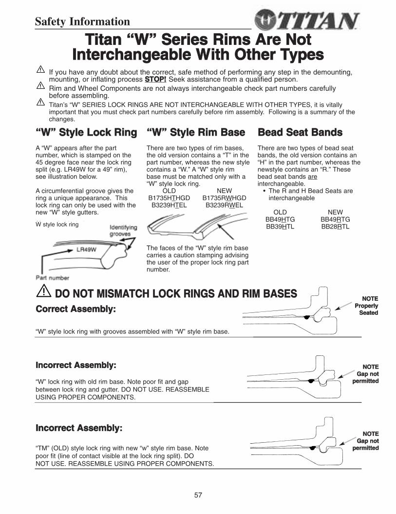
TTiittaann ““WW”” SSeerriieess RRiimmss AArree NNoottIInntteerrcchhaannggeeaabbllee WWiitthh OOtthheerr TTyyppeess
““WW”” SSttyyllee LLoocckk RRiinnggA “W” appears after the partnumber, which is stamped on the45 degree face near the lock ringsplit (e.g. LR49W for a 49” rim),see illustration below.
A circumferential groove gives thering a unique appearance. Thislock ring can only be used with thenew “W” style gutters.
““WW”” SSttyyllee RRiimm BBaasseeThere are two types of rim bases,the old version contains a “T” in thepart number, whereas the new stylecontains a “W.” A “W” style rimbase must be matched only with a“W” style lock ring.
OLD NEWB1735HTHGD B1735RWHGDB3239HTEL B3239RWEL
The faces of the “W” style rim basecarries a caution stamping advisingthe user of the proper lock ring partnumber.
BBeeaadd SSeeaatt BBaannddssThere are two types of bead seatbands, the old version contains an“H” in the part number, whereas thenewstyle contains an “R.” Thesebead seat bands areinterchangeable.
• The R and H Bead Seats areinterchangeable
OLD NEWBB49HTG BB49RTGBB39HTL BB28RTL
CCoorrrreecctt AAsssseemmbbllyy::
IInnccoorrrreecctt AAsssseemmbbllyy::
IInnccoorrrreecctt AAsssseemmbbllyy::
If you have any doubt about the correct, safe method of performing any step in the demounting,mounting, or inflating process SSTTOOPP!! Seek assistance from a qualified person.Rim and Wheel Components are not always interchangeable check part numbers carefullybefore assembling.Titan’s “W” SERIES LOCK RINGS ARE NOT INTERCHANGEABLE WITH OTHER TYPES, it is vitallyimportant that you must check part numbers carefully before rim assembly. Following is a summary of thechanges.
W style lock ring
“W” style lock ring with grooves assembled with “W” style rim base.
“W” lock ring with old rim base. Note poor fit and gapbetween lock ring and gutter. DO NOT USE. REASSEMBLEUSING PROPER COMPONENTS.
“TM” (OLD) style lock ring with new “w” style rim base. Note poor fit (line of contact visible at the lock ring split). DO NOT USE. REASSEMBLE USING PROPER COMPONENTS.
NNOOTTEEGGaapp nnoott
ppeerrmmiitttteedd
NNOOTTEEPPrrooppeerrllyy
SSeeaatteedd
NNOOTTEEGGaapp nnoott
ppeerrmmiitttteedd
DDOO NNOOTT MMIISSMMAATTCCHH LLOOCCKK RRIINNGGSS AANNDD RRIIMM BBAASSEESS
58
Safety Information
OOuuttbbooaarrdd DDrriivveerr KKeeyyssIInnssttrruuccttiioonnss
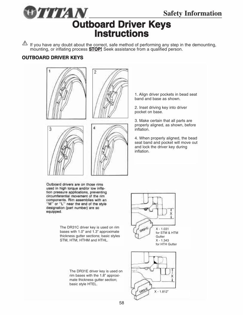
If you have any doubt about the correct, safe method of performing any step in the demounting,mounting, or inflating process SSTTOOPP!! Seek assistance from a qualified person.
OOUUTTBBOOAARRDD DDRRIIVVEERR KKEEYYSS
3
2
The DR31C driver key is used on rimbases with 1.0” and 1.3” approximatethickness gutter sections; basic stylesSTM, HTM, HTHM and HTHL.
The DR31E driver key is used onrim bases with the 1.8” approxi-mate thickness gutter section;basic style HTEL.
X - 1.031for STM & HTMGutterX - 1.343 for HTH Gutter
X - 1.812”
X
X
1. Align driver pockets in bead seatband and base as shown.
2. Inset driving key into driverpocket on base.
3. Make certain that all parts areproperly aligned, as shown, beforeinflation.
4. When properly aligned, the beadseat band and pocket will move outand lock the driver key during inflation.
59
Safety Information
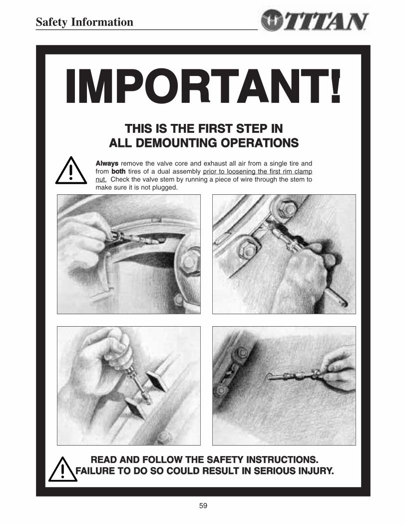
IIMMPPOORRTTAANNTT!!TTHHIISS IISS TTHHEE FFIIRRSSTT SSTTEEPP IINN
AALLLL DDEEMMOOUUNNTTIINNGG OOPPEERRAATTIIOONNSS
AAllwwaayyss remove the valve core and exhaust all air from a single tire andfrom bbootthh tires of a dual assembly prior to loosening the first rim clampnut. Check the valve stem by running a piece of wire through the stem tomake sure it is not plugged.
RREEAADD AANNDD FFOOLLLLOOWW TTHHEE SSAAFFEETTYY IINNSSTTRRUUCCTTIIOONNSS..FFAAIILLUURREE TTOO DDOO SSOO CCOOUULLDD RREESSUULLTT IINN SSEERRIIOOUUSS IINNJJUURRYY..
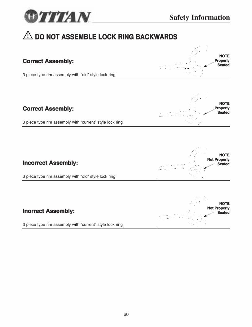
NNOOTTEEPPrrooppeerrllyy
SSeeaatteedd
Safety Information
60
CCoorrrreecctt AAsssseemmbbllyy::
3 piece type rim assembly with “old” style lock ring
NNOOTTEEPPrrooppeerrllyy
SSeeaatteeddCCoorrrreecctt AAsssseemmbbllyy::
3 piece type rim assembly with “current” style lock ring
NNOOTTEENNoott PPrrooppeerrllyy
SSeeaatteeddIInnoorrrreecctt AAsssseemmbbllyy::
3 piece type rim assembly with “current” style lock ring
NNOOTTEENNoott PPrrooppeerrllyy
SSeeaatteeddIInnccoorrrreecctt AAsssseemmbbllyy::
3 piece type rim assembly with “old” style lock ring
DDOO NNOOTT AASSSSEEMMBBLLEE LLOOCCKK RRIINNGG BBAACCKKWWAARRDDSS
61
Safety Information
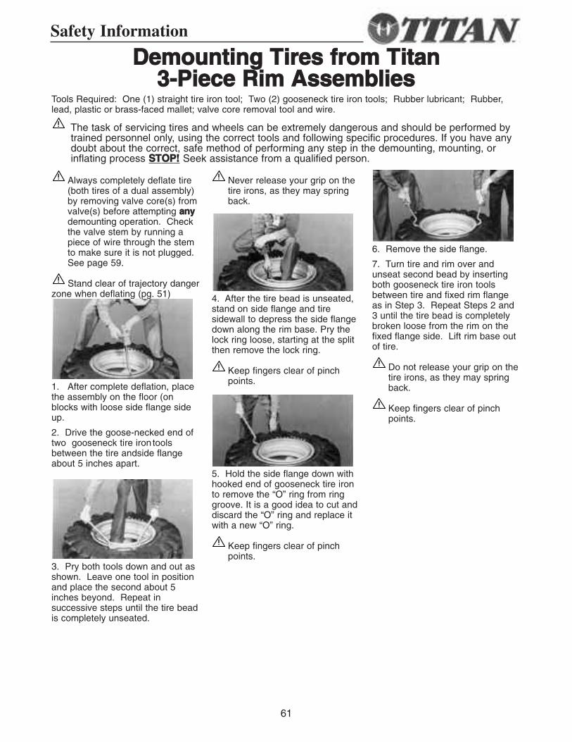
DDeemmoouunnttiinngg TTiirreess ffrroomm TTiittaann 33--PPiieeccee RRiimm AAsssseemmbblliieess
Always completely deflate tire(both tires of a dual assembly)by removing valve core(s) fromvalve(s) before attempting aannyydemounting operation. Checkthe valve stem by running apiece of wire through the stemto make sure it is not plugged.See page 59.
Stand clear of trajectory dangerzone when deflating (pg. 51)
1. After complete deflation, placethe assembly on the floor (onblocks with loose side flange sideup.
2. Drive the goose-necked end oftwo gooseneck tire iron toolsbetween the tire andside flangeabout 5 inches apart.
3. Pry both tools down and out asshown. Leave one tool in positionand place the second about 5inches beyond. Repeat insuccessive steps until the tire beadis completely unseated.
Never release your grip on thetire irons, as they may springback.
4. After the tire bead is unseated,stand on side flange and tiresidewall to depress the side flangedown along the rim base. Pry thelock ring loose, starting at the splitthen remove the lock ring.
Keep fingers clear of pinchpoints.
5. Hold the side flange down withhooked end of gooseneck tire ironto remove the “O” ring from ringgroove. It is a good idea to cut anddiscard the “O” ring and replace itwith a new “O” ring.
Keep fingers clear of pinchpoints.
6. Remove the side flange.
7. Turn tire and rim over andunseat second bead by insertingboth gooseneck tire iron toolsbetween tire and fixed rim flangeas in Step 3. Repeat Steps 2 and3 until the tire bead is completelybroken loose from the rim on thefixed flange side. Lift rim base outof tire.
Do not release your grip on thetire irons, as they may springback.
Keep fingers clear of pinchpoints.
Tools Required: One (1) straight tire iron tool; Two (2) gooseneck tire iron tools; Rubber lubricant; Rubber,lead, plastic or brass-faced mallet; valve core removal tool and wire.
The task of servicing tires and wheels can be extremely dangerous and should be performed bytrained personnel only, using the correct tools and following specific procedures. If you have anydoubt about the correct, safe method of performing any step in the demounting, mounting, orinflating process SSTTOOPP!! Seek assistance from a qualified person.
62
1. Clean the rim base and allcomponents thoroughly with a wirebrush to facilitate inspection,maintenance and mounting.
Clean all dirt and rust frominter-locking faces of multi-piece rim componentsparticularly the gutter sectionswhich hold the lock ring and“O” ring in place. Failure toadequately clean allcomponents will inhibit effortsto inspect, maintain, andreassemble the tire and wheelcorrectly.
2. Inspect rim base and wheelcomponents for cracks, wear,corrosion and damage.
Parts that are cracked, worn,pitted with corrosion, ordamaged must be destroyedand replace with good parts.
In situations where partcondition is suspect or in doubtdestroy the part, discard andreplace with good part.
Do not, under anycircumstances, attempt torework, weld, heat, or brazeany rim base or wheelcomponents.
Verify that the replacementparts are the correct size andtype and manufacturer for thewheel being assembled.
3. After the rim and wheelcomponent inspection is complete,and rim base and wheelcomponents are verified to be ingood usuable condition, repaint allbare metal with a rust inhibitor toretard detrimental effects ofcorrosion.
Follow procedures and safetyprecautions of the paint
manufacturer.4. Inspect the tire for wear, cracks,tears, punctures and otherdamage.
Tires with excessive or unevenwear, cracks, tears, punctures,blisters or other damage mayexplode during inflation orservice and tire should bedestroyed and replaced withgood tire of correct size, typeand manufacturer for assembly,machine, and application.
If in doubt of the condition ofthe rim base, wheelcomponents, or tire - STOP -contact the manufacturer ordistributor for assistance.
Make sure parts are clean,repainted if necessary, and havebeen inspected for damage andcracks, before proceeding withmounting.
Parts that are cracked, worn,pitted with corrosion, ordamaged must be renderedunusable, discarded, andreplaced with good parts.
5. Install valve spud on rim.
Follow valve spudmanufacturer’srecommendations andinstallation instructions.
6. Place rim base on blocks withfixed flange side down. Lubricateboth bead seats of the tire withvegetable base lubricant. Place tire over rim base.
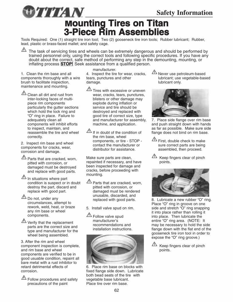
Never use petroleum-basedlubricant; use vegetable-basedlubricant only.
7. Place side flange over rim baseand push straight down with handsas far as possible. Make sure sideflange does not bind on rim base.
First, double check to makesure correct parts are beingassembled, then proceed.
Keep fingers clear of pinchpoints.
8. Lubricate a new rubber “O” ring.Place “O” ring in groove on oneside and stretch “O” ring snappingit into place rather than rolling itinto place. Then lubricate theentire “O” ring area. (NOTE: Itmay be necessary to hold the sideflange down with the flat end of thegooseneck tire iron tool in order toexpose the “O” ring groove.)
Keep fingers clear of pinchpoints.
MMoouunnttiinngg TTiirreess oonn TTiittaann 33--PPiieeccee RRiimm AAsssseemmbblliieess
Tools Required: One (1) straight tire iron tool; Two (2) gooseneck tire iron tools; Rubber lubricant; Rubber,lead, plastic or brass-faced mallet; and safety cage.
Safety Information
The task of servicing tires and wheels can be extremely dangerous and should be performed bytrained personnel only, using the correct tools and following specific procedures. If you have anydoubt about the correct, safe method of performing any step in the demounting, mounting, orinflating process SSTTOOPP!! Seek assistance from a qualified person.
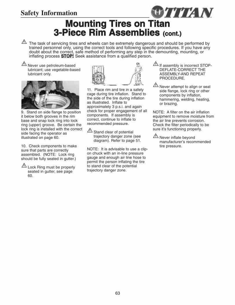
63
Safety Information
MMoouunnttiinngg TTiirreess oonn TTiittaann 33--PPiieeccee RRiimm AAsssseemmbblliieess ((ccoonntt..))
Never use petroleum-basedlubricant; use vegetable-basedlubricant only.
9. Stand on side flange to positionit below both grooves in the rimbase and snap lock ring into lockring (upper) groove. Be certain thelock ring is installed with the correctside facing the operator asillustrated on page 60.
10. Check components to makesure that parts are correctlyassembled. (NOTE: Lock ringshould be fully seated in gutter.)
Lock Ring must be properlyseated in gutter, see page 60.
11. Place rim and tire in a safetycage during tire inflation. Stand tothe side of the tire during inflationas illustrated. Inflate toapproximately 3 p.s.i. and againcheck for proper engagement of allcomponents. If assembly iscorrect, continue to inflate torecommended pressure.
Stand clear of potentialtrajectory danger zone (seediagram). Refer to page 51.
NOTE: It is advisable to use a clip-on chuck with an in-line pressuregauge and enough air line hose topermit the person inflating the tireto stand clear of the potentialtrajectory danger zone.
If assembly is incorrect STOP-DEFLATE-CORRECT THEASSEMBLY-AND REPEATPROCEDURE.
Never attempt to align or seatside flange, lock ring or othercomponents by inflation,hammering, welding, heating,or brazing.
NOTE: A filter on the air inflationequipment to remove moisture fromthe air line prevents corrosion.Check the filter periodically to besure it’s functioning properly.
Never inflate beyondmanufacturer’s recommendedtire pressure.
The task of servicing tires and wheels can be extremely dangerous and should be performed bytrained personnel only, using the correct tools and following specific procedures. If you have anydoubt about the correct, safe method of performing any step in the demounting, mounting, orinflating process SSTTOOPP!! Seek assistance from a qualified person.
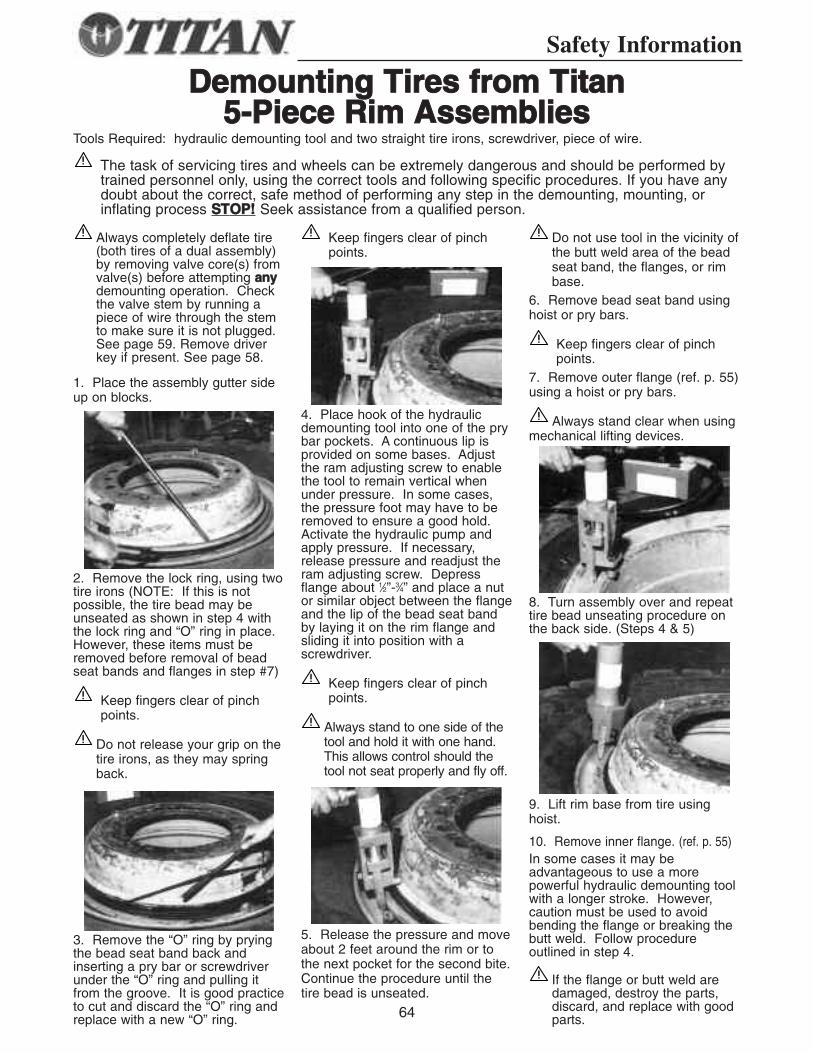
DDeemmoouunnttiinngg TTiirreess ffrroomm TTiittaann55--PPiieeccee RRiimm AAsssseemmbblliieess
Tools Required: hydraulic demounting tool and two straight tire irons, screwdriver, piece of wire.
Always completely deflate tire(both tires of a dual assembly)by removing valve core(s) fromvalve(s) before attempting aannyydemounting operation. Checkthe valve stem by running apiece of wire through the stemto make sure it is not plugged.See page 59. Remove driverkey if present. See page 58.
1. Place the assembly gutter sideup on blocks.
2. Remove the lock ring, using twotire irons (NOTE: If this is notpossible, the tire bead may beunseated as shown in step 4 withthe lock ring and “O” ring in place.However, these items must beremoved before removal of beadseat bands and flanges in step #7)
Keep fingers clear of pinchpoints.
Do not release your grip on thetire irons, as they may springback.
3. Remove the “O” ring by pryingthe bead seat band back andinserting a pry bar or screwdriverunder the “O” ring and pulling itfrom the groove. It is good practiceto cut and discard the “O” ring andreplace with a new “O” ring.
Keep fingers clear of pinchpoints.
4. Place hook of the hydraulicdemounting tool into one of the prybar pockets. A continuous lip isprovided on some bases. Adjustthe ram adjusting screw to enablethe tool to remain vertical whenunder pressure. In some cases,the pressure foot may have to beremoved to ensure a good hold.Activate the hydraulic pump andapply pressure. If necessary,release pressure and readjust theram adjusting screw. Depressflange about 1⁄2”-3⁄4” and place a nutor similar object between the flangeand the lip of the bead seat bandby laying it on the rim flange andsliding it into position with ascrewdriver.
Keep fingers clear of pinchpoints.
Always stand to one side of thetool and hold it with one hand.This allows control should thetool not seat properly and fly off.
5. Release the pressure and moveabout 2 feet around the rim or tothe next pocket for the second bite.Continue the procedure until thetire bead is unseated.
Do not use tool in the vicinity ofthe butt weld area of the beadseat band, the flanges, or rimbase.
6. Remove bead seat band usinghoist or pry bars.
Keep fingers clear of pinchpoints.
7. Remove outer flange (ref. p. 55)using a hoist or pry bars.
Always stand clear when usingmechanical lifting devices.
8. Turn assembly over and repeattire bead unseating procedure onthe back side. (Steps 4 & 5)
9. Lift rim base from tire usinghoist.
10. Remove inner flange. (ref. p. 55)In some cases it may beadvantageous to use a morepowerful hydraulic demounting toolwith a longer stroke. However,caution must be used to avoidbending the flange or breaking thebutt weld. Follow procedureoutlined in step 4.
If the flange or butt weld aredamaged, destroy the parts,discard, and replace with goodparts.64
Safety Information
The task of servicing tires and wheels can be extremely dangerous and should be performed bytrained personnel only, using the correct tools and following specific procedures. If you have anydoubt about the correct, safe method of performing any step in the demounting, mounting, orinflating process SSTTOOPP!! Seek assistance from a qualified person.
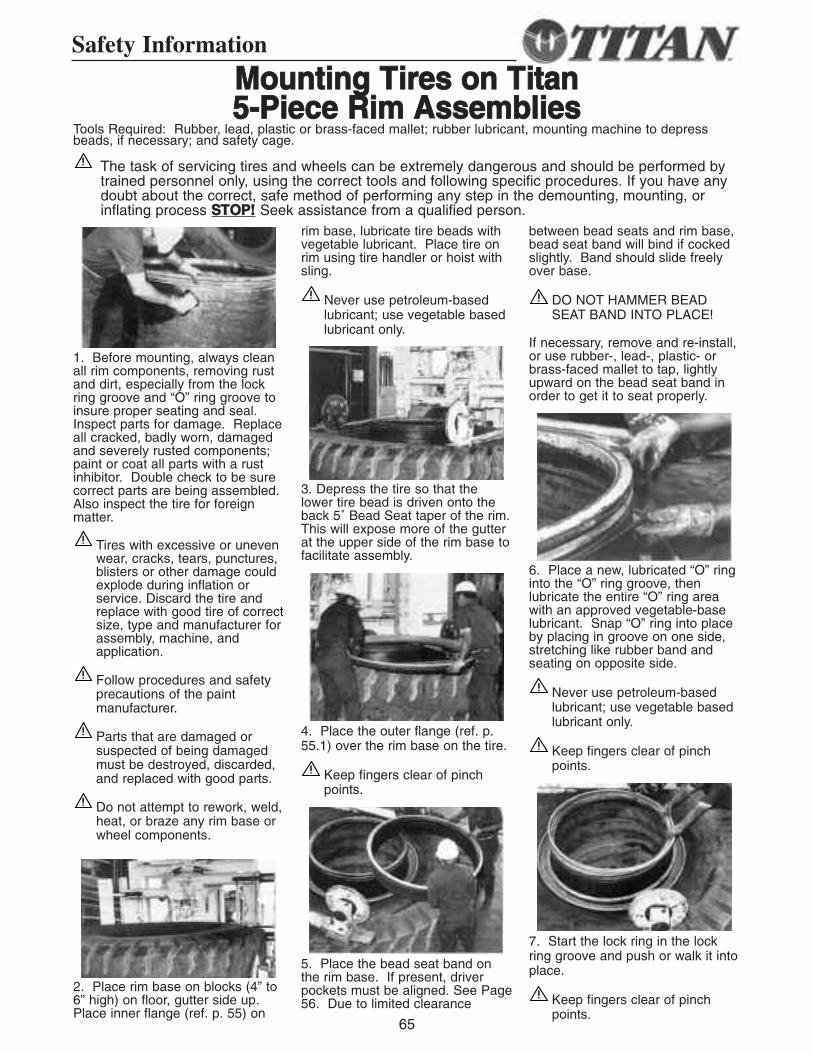
Safety Information
MMoouunnttiinngg TTiirreess oonn TTiittaann55--PPiieeccee RRiimm AAsssseemmbblliieess
1. Before mounting, always cleanall rim components, removing rustand dirt, especially from the lockring groove and “O” ring groove toinsure proper seating and seal.Inspect parts for damage. Replaceall cracked, badly worn, damagedand severely rusted components;paint or coat all parts with a rustinhibitor. Double check to be surecorrect parts are being assembled.Also inspect the tire for foreignmatter.
Tires with excessive or unevenwear, cracks, tears, punctures,blisters or other damage couldexplode during inflation orservice. Discard the tire andreplace with good tire of correctsize, type and manufacturer forassembly, machine, andapplication.
Follow procedures and safetyprecautions of the paintmanufacturer.
Parts that are damaged orsuspected of being damagedmust be destroyed, discarded,and replaced with good parts.
Do not attempt to rework, weld,heat, or braze any rim base orwheel components.
2. Place rim base on blocks (4” to6” high) on floor, gutter side up.Place inner flange (ref. p. 55) on
rim base, lubricate tire beads withvegetable lubricant. Place tire onrim using tire handler or hoist withsling.
Never use petroleum-basedlubricant; use vegetable basedlubricant only.
3. Depress the tire so that thelower tire bead is driven onto theback 5˚ Bead Seat taper of the rim.This will expose more of the gutterat the upper side of the rim base tofacilitate assembly.
4. Place the outer flange (ref. p.55.1) over the rim base on the tire.
Keep fingers clear of pinchpoints.
5. Place the bead seat band onthe rim base. If present, driverpockets must be aligned. See Page56. Due to limited clearance
between bead seats and rim base, bead seat band will bind if cockedslightly. Band should slide freelyover base.
DO NOT HAMMER BEADSEAT BAND INTO PLACE!
If necessary, remove and re-install,or use rubber-, lead-, plastic- orbrass-faced mallet to tap, lightlyupward on the bead seat band inorder to get it to seat properly.
6. Place a new, lubricated “O” ringinto the “O” ring groove, thenlubricate the entire “O” ring areawith an approved vegetable-baselubricant. Snap “O” ring into placeby placing in groove on one side,stretching like rubber band andseating on opposite side.
Never use petroleum-basedlubricant; use vegetable basedlubricant only.
Keep fingers clear of pinchpoints.
7. Start the lock ring in the lockring groove and push or walk it intoplace.
Keep fingers clear of pinchpoints.
Tools Required: Rubber, lead, plastic or brass-faced mallet; rubber lubricant, mounting machine to depressbeads, if necessary; and safety cage.
65
The task of servicing tires and wheels can be extremely dangerous and should be performed bytrained personnel only, using the correct tools and following specific procedures. If you have anydoubt about the correct, safe method of performing any step in the demounting, mounting, orinflating process SSTTOOPP!! Seek assistance from a qualified person.
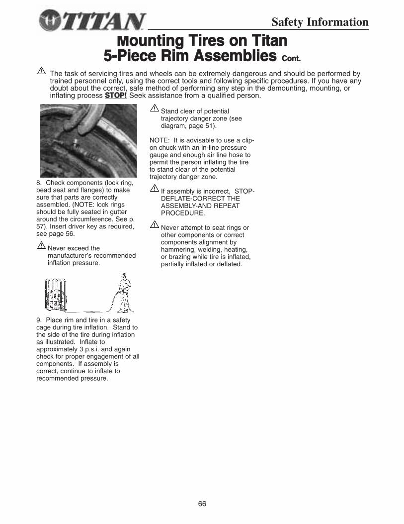
66
MMoouunnttiinngg TTiirreess oonn TTiittaann55--PPiieeccee RRiimm AAsssseemmbblliieess CCoonntt..
8. Check components (lock ring,bead seat and flanges) to makesure that parts are correctlyassembled. (NOTE: lock ringsshould be fully seated in gutteraround the circumference. See p.57). Insert driver key as required,see page 56.
Never exceed themanufacturer’s recommendedinflation pressure.
9. Place rim and tire in a safetycage during tire inflation. Stand tothe side of the tire during inflationas illustrated. Inflate toapproximately 3 p.s.i. and againcheck for proper engagement of allcomponents. If assembly iscorrect, continue to inflate torecommended pressure.
Stand clear of potentialtrajectory danger zone (seediagram, page 51).
NOTE: It is advisable to use a clip-on chuck with an in-line pressuregauge and enough air line hose topermit the person inflating the tireto stand clear of the potentialtrajectory danger zone.
If assembly is incorrect, STOP-DEFLATE-CORRECT THEASSEMBLY-AND REPEATPROCEDURE.
Never attempt to seat rings orother components or correctcomponents alignment byhammering, welding, heating,or brazing while tire is inflated,partially inflated or deflated.
Safety Information
The task of servicing tires and wheels can be extremely dangerous and should be performed bytrained personnel only, using the correct tools and following specific procedures. If you have anydoubt about the correct, safe method of performing any step in the demounting, mounting, orinflating process SSTTOOPP!! Seek assistance from a qualified person.
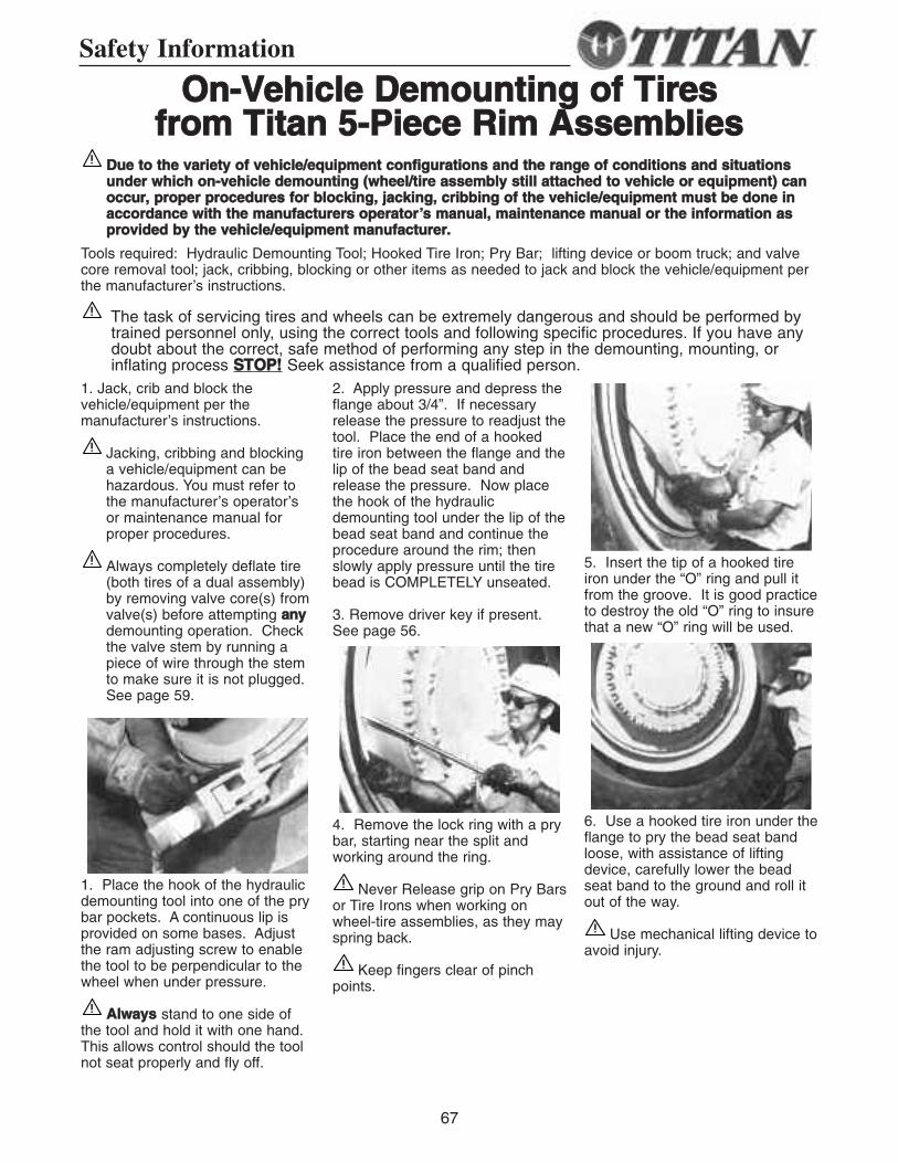
67
Safety Information
OOnn--VVeehhiiccllee DDeemmoouunnttiinngg ooff TTiirreess ffrroomm TTiittaann 55--PPiieeccee RRiimm AAsssseemmbblliieess
DDuuee ttoo tthhee vvaarriieettyy ooff vveehhiiccllee//eeqquuiippmmeenntt ccoonnffiigguurraattiioonnss aanndd tthhee rraannggee ooff ccoonnddiittiioonnss aanndd ssiittuuaattiioonnssuunnddeerr wwhhiicchh oonn--vveehhiiccllee ddeemmoouunnttiinngg ((wwhheeeell//ttiirree aasssseemmbbllyy ssttiillll aattttaacchheedd ttoo vveehhiiccllee oorr eeqquuiippmmeenntt)) ccaannooccccuurr,, pprrooppeerr pprroocceedduurreess ffoorr bblloocckkiinngg,, jjaacckkiinngg,, ccrriibbbbiinngg ooff tthhee vveehhiiccllee//eeqquuiippmmeenntt mmuusstt bbee ddoonnee iinnaaccccoorrddaannccee wwiitthh tthhee mmaannuuffaaccttuurreerrss ooppeerraattoorr’’ss mmaannuuaall,, mmaaiinntteennaannccee mmaannuuaall oorr tthhee iinnffoorrmmaattiioonn aasspprroovviiddeedd bbyy tthhee vveehhiiccllee//eeqquuiippmmeenntt mmaannuuffaaccttuurreerr..
Tools required: Hydraulic Demounting Tool; Hooked Tire Iron; Pry Bar; lifting device or boom truck; and valvecore removal tool; jack, cribbing, blocking or other items as needed to jack and block the vehicle/equipment perthe manufacturer’s instructions.
1. Jack, crib and block thevehicle/equipment per themanufacturer’s instructions.
Jacking, cribbing and blockinga vehicle/equipment can behazardous. You must refer tothe manufacturer’s operator’sor maintenance manual forproper procedures.
Always completely deflate tire(both tires of a dual assembly)by removing valve core(s) fromvalve(s) before attempting aannyydemounting operation. Checkthe valve stem by running apiece of wire through the stemto make sure it is not plugged.See page 59.
1. Place the hook of the hydraulicdemounting tool into one of the prybar pockets. A continuous lip isprovided on some bases. Adjustthe ram adjusting screw to enablethe tool to be perpendicular to thewheel when under pressure.
AAllwwaayyss stand to one side ofthe tool and hold it with one hand.This allows control should the toolnot seat properly and fly off.
2. Apply pressure and depress theflange about 3/4”. If necessaryrelease the pressure to readjust thetool. Place the end of a hookedtire iron between the flange and thelip of the bead seat band andrelease the pressure. Now placethe hook of the hydraulicdemounting tool under the lip of thebead seat band and continue theprocedure around the rim; thenslowly apply pressure until the tirebead is COMPLETELY unseated.
3. Remove driver key if present.See page 56.
4. Remove the lock ring with a prybar, starting near the split andworking around the ring.
Never Release grip on Pry Barsor Tire Irons when working onwheel-tire assemblies, as they mayspring back.
Keep fingers clear of pinchpoints.
5. Insert the tip of a hooked tireiron under the “O” ring and pull itfrom the groove. It is good practiceto destroy the old “O” ring to insurethat a new “O” ring will be used.
6. Use a hooked tire iron under theflange to pry the bead seat bandloose, with assistance of liftingdevice, carefully lower the beadseat band to the ground and roll itout of the way.
Use mechanical lifting device toavoid injury.
The task of servicing tires and wheels can be extremely dangerous and should be performed bytrained personnel only, using the correct tools and following specific procedures. If you have anydoubt about the correct, safe method of performing any step in the demounting, mounting, orinflating process SSTTOOPP!! Seek assistance from a qualified person.
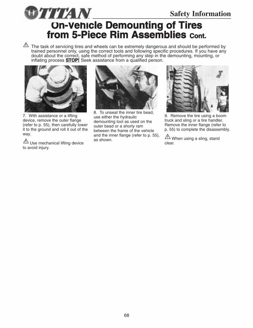
68
OOnn--VVeehhiiccllee DDeemmoouunnttiinngg ooff TTiirreess ffrroomm 55--PPiieeccee RRiimm AAsssseemmbblliieess CCoonntt..
7. With assistance or a liftingdevice, remove the outer flange(refer to p. 55), then carefully lowerit to the ground and roll it out of theway.
Use mechanical lifting device to avoid injury.
8. To unseat the inner tire bead,use either the hydraulicdemounting tool as used on theouter bead or a shorty rambetween the frame of the vehicleand the inner flange (refer to p. 55),as shown.
9. Remove the tire using a boomtruck and sling or a tire handler.Remove the inner flange (refer top. 55) to complete the disassembly.
When using a sling, stand clear.
Safety Information
The task of servicing tires and wheels can be extremely dangerous and should be performed bytrained personnel only, using the correct tools and following specific procedures. If you have anydoubt about the correct, safe method of performing any step in the demounting, mounting, orinflating process SSTTOOPP!! Seek assistance from a qualified person.
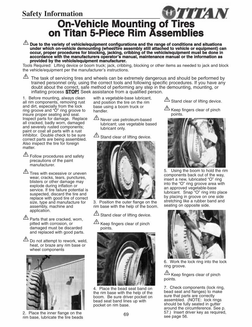
69
Safety Information
OOnn--VVeehhiiccllee MMoouunnttiinngg ooff TTiirreessoonn TTiittaann 55--PPiieeccee RRiimm AAsssseemmbblliieess
1. Before mounting, always cleanall rim components, removing rustand dirt, especially from the lockring groove and “O” ring groove toinsure proper seating and seal.Inspect parts for damage. Replaceall cracked, badly worn, damagedand severely rusted components;paint or coat all parts with a rustinhibitor. Double check to be surecorrect parts are being assembled.Also inspect the tire for foreignmatter.
Follow procedures and safetyprecautions of the paintmanufacturer.
Tires with excessive or unevenwear, cracks, tears, punctures,blisters or other damage mayexplode during inflation orservice. If tire failure potential issuspected, discard the tire andreplace with good tire of correctsize, type and manufacture forassembly, machine andapplication.
Parts that are cracked, worn,pitted with corrosion, ordamaged must be discardedand replaced with good parts.
Do not attempt to rework, weld,heat, or braze any rim base orwheel components
2. Place the inner flange on therim base, lubricate the tire beads
with a vegetable-base lubricant,and position the tire on the rimbase using a boom truck orhandler.
Never use petroleum-basedlubricant; use vegetable basedlubricant only.
Stand clear of lifting device.
3. Position the outer flange on therim base with the help of the boom.
Stand clear of lifting device.
Keep fingers clear of pinchpoints.
4. Place the bead seat band onthe rim base with the help of theboom. Be sure driver pocket onbead seat band lines up withpocket on rim base.
Stand clear of lifting device.
Keep fingers clear of pinchpoints.
5. Using the boom to hold the rimcomponents back out of the way,insert a new, lubricated “O” ringinto the “O” ring groove area withan approved vegetable-baselubricant. Snap “O” ring into placeby placing in groove on one sidestretching like a rubber band andseating on opposite side.
6. Work the lock ring into the lockring groove.
Keep fingers clear of pinchpoints.
7. Check components (lock ring,bead seat and flanges) to makesure that parts are correctlyassembled. (NOTE: lock ringsshould be fully seated in gutteraround the circumference. See p.57.) Insert driver key as required,see page 56.
DDuuee ttoo tthhee vvaarriieettyy ooff vveehhiiccllee//eeqquuiippmmeenntt ccoonnffiigguurraattiioonnss aanndd tthhee rraannggee ooff ccoonnddiittiioonnss aanndd ssiittuuaattiioonnssuunnddeerr wwhhiicchh oonn--vveehhiiccllee ddeemmoouunnttiinngg ((wwhheeeell//ttiirree aasssseemmbbllyy ssttiillll aattttaacchheedd ttoo vveehhiiccllee oorr eeqquuiippmmeenntt)) ccaannooccccuurr,, pprrooppeerr pprroocceedduurreess ffoorr bblloocckkiinngg,, jjaacckkiinngg,, ccrriibbbbiinngg ooff tthhee vveehhiiccllee//eeqquuiippmmeenntt mmuusstt bbee ddoonnee iinnaaccccoorrddaannccee wwiitthh tthhee mmaannuuffaaccttuurreerrss ooppeerraattoorr’’ss mmaannuuaall,, mmaaiinntteennaannccee mmaannuuaall oorr tthhee iinnffoorrmmaattiioonn aasspprroovviiddeedd bbyy tthhee vveehhiiccllee//eeqquuiippmmeenntt mmaannuuffaaccttuurreerr..
Tools Required: Lifting device or boom truck; jack, cribbing, blocking or other items as needed to jack and blockthe vehicle/equipment per the manufacturer’s instructions.
The task of servicing tires and wheels can be extremely dangerous and should be performed bytrained personnel only, using the correct tools and following specific procedures. If you have anydoubt about the correct, safe method of performing any step in the demounting, mounting, orinflating process SSTTOOPP!! Seek assistance from a qualified person.
70
OOnn--VVeehhiiccllee MMoouunnttiinngg ooff TTiirreessoonn TTiittaann 55--PPiieeccee RRiimm AAsssseemmbblliieess ((ccoonntt..))
Use a clip-on chuck with and in-linepressure gauge and enough air linehose to permit the person inflatingthe tire to stand clear of thepotential trajectory danger zone.(See p. 51) Stand to the side of thetire during inflation. Inflate toapproximately 3 p.s.i. and againcheck for proper engagement of allcomponents. If assembly iscorrect, continue to inflate torecommended pressure.
Stand clear of potentialtrajectory danger zone (see p.51 illustration).
If assembly is incorrect, STOP-DEFLATE-CORRECT THEASSEMBLY-AND REPEATPROCEDURE.
Never attempt to inflate anassembly if components arenot properly aligned. Neverattempt to seat rings or othercomponents or correctcomponents alignment byhammering, welding, heating,or brazing while tire is inflated,partially inflated or deflated.
NOTE: A filter on the air inflationequipment to remove moisture fromthe air line prevents a lot ofcorrosion. Check the filterperiodically to be sure it’sfunctioning properly.
Never inflate beyondmanufacturer’s recommendedtire pressure.
Safety Information
The task of servicing tires and wheels can be extremely dangerous and should be performed bytrained personnel only, using the correct tools and following specific procedures. If you have anydoubt about the correct, safe method of performing any step in the demounting, mounting, orinflating process SSTTOOPP!! Seek assistance from a qualified person.

TITAN WHEEL CORPORATION2701 Spruce StreetQuincy, IL 62301(217) 228-6011
Fax: (217) 228-9331www.titan-intl.com