Embed Size (px)
Citation preview
FILE: EARTH TESTING 20-Oct-09 PROVISIONAL APPLICATION NOTE (FOR CHINESE MARKET)
1
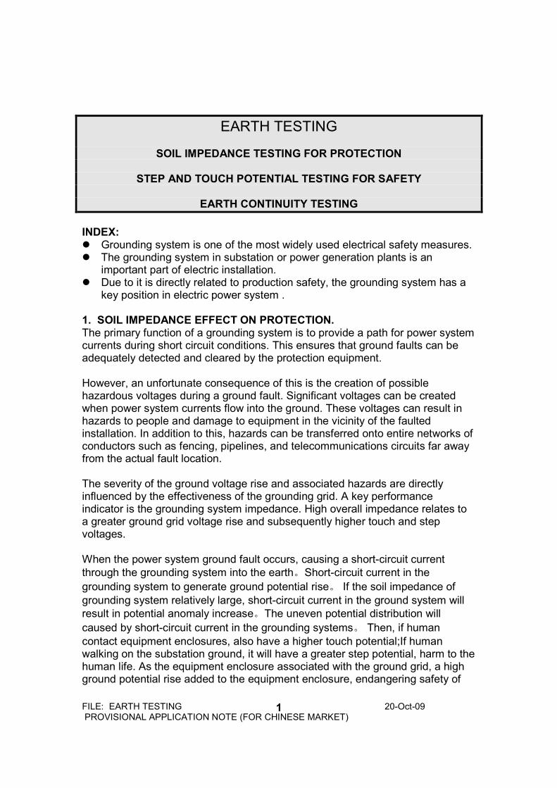
EARTH TESTING
SOIL IMPEDANCE TESTING FOR PROTECTION
STEP AND TOUCH POTENTIAL TESTING FOR SAFETY
EARTH CONTINUITY TESTING
INDEX: Grounding system is one of the most widely used electrical safety measures. The grounding system in substation or power generation plants is an
important part of electric installation. Due to it is directly related to production safety, the grounding system has a
key position in electric power system . 1. SOIL IMPEDANCE EFFECT ON PROTECTION. The primary function of a grounding system is to provide a path for power system currents during short circuit conditions. This ensures that ground faults can be adequately detected and cleared by the protection equipment. However, an unfortunate consequence of this is the creation of possible hazardous voltages during a ground fault. Significant voltages can be created when power system currents flow into the ground. These voltages can result in hazards to people and damage to equipment in the vicinity of the faulted installation. In addition to this, hazards can be transferred onto entire networks of conductors such as fencing, pipelines, and telecommunications circuits far away from the actual fault location. The severity of the ground voltage rise and associated hazards are directly influenced by the effectiveness of the grounding grid. A key performance indicator is the grounding system impedance. High overall impedance relates to a greater ground grid voltage rise and subsequently higher touch and step voltages. When the power system ground fault occurs, causing a short-circuit current
through the grounding system into the earth。Short-circuit current in the
grounding system to generate ground potential rise。 If the soil impedance of
grounding system relatively large, short-circuit current in the ground system will
result in potential anomaly increase。The uneven potential distribution will
caused by short-circuit current in the grounding systems。 Then, if human
contact equipment enclosures, also have a higher touch potential;If human walking on the substation ground, it will have a greater step potential, harm to the human life. As the equipment enclosure associated with the ground grid, a high ground potential rise added to the equipment enclosure, endangering safety of
FILE: EARTH TESTING 20-Oct-09 PROVISIONAL APPLICATION NOTE (FOR CHINESE MARKET)
2
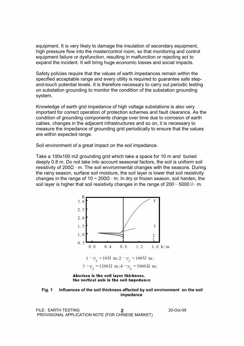
equipment. It is very likely to damage the insulation of secondary equipment, high pressure flow into the mastercontrol room, so that monitoring and control equipment failure or dysfunction, resulting in malfunction or rejecting act to expand the incident. It will bring huge economic losses and social impacts. Safety policies require that the values of earth impedances remain within the specified acceptable range and every utility is required to guarantee safe step-and-touch potential levels. It is therefore necessary to carry out periodic testing on substation grounding to monitor the condition of the substation grounding system. Knowledge of earth grid impedance of high voltage substations is also very important for correct operation of protection schemes and fault clearance. As the condition of grounding components change over time due to corrosion of earth cables, changes in the adjacent infrastructures and so on, it is necessary to measure the impedance of grounding grid periodically to ensure that the values are within expected range. Soil environment of a great impact on the soil impedance. Take a 100x100 m2 grounding grid which take a space for 10 m and buried deeply 0.8 m. Do not take into account seasonal factors, the soil is uniform soil resistivity of 200Ω · m. The soil environmental changes with the seasons. During the rainy season, surface soil moisture, the soil layer is lower that soil resistivity changes in the range of 10 ~ 200Ω · m. In dry or frozen season, soil harden, the
soil layer is higher that soil resistivity changes in the range of 200~5000Ω· m.
Fig. 1 Influences of the soil thickness affected by soil environment on the soil
impedance
FILE: EARTH TESTING 20-Oct-09 PROVISIONAL APPLICATION NOTE (FOR CHINESE MARKET)
3
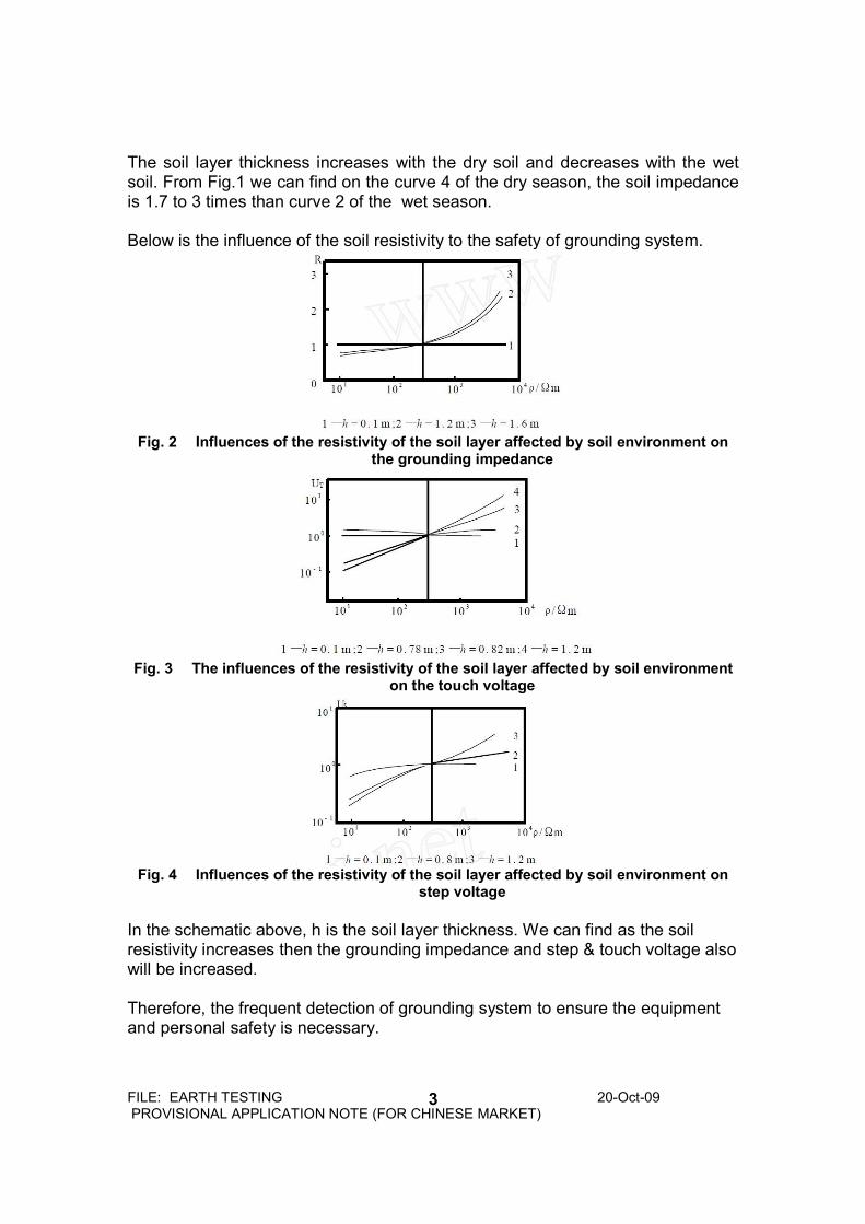
The soil layer thickness increases with the dry soil and decreases with the wet soil. From Fig.1 we can find on the curve 4 of the dry season, the soil impedance is 1.7 to 3 times than curve 2 of the wet season. Below is the influence of the soil resistivity to the safety of grounding system.
Fig. 2 Influences of the resistivity of the soil layer affected by soil environment on
the grounding impedance
Fig. 3 The influences of the resistivity of the soil layer affected by soil environment
on the touch voltage
Fig. 4 Influences of the resistivity of the soil layer affected by soil environment on
step voltage
In the schematic above, h is the soil layer thickness. We can find as the soil resistivity increases then the grounding impedance and step & touch voltage also will be increased. Therefore, the frequent detection of grounding system to ensure the equipment and personal safety is necessary.
FILE: EARTH TESTING 20-Oct-09 PROVISIONAL APPLICATION NOTE (FOR CHINESE MARKET)
4
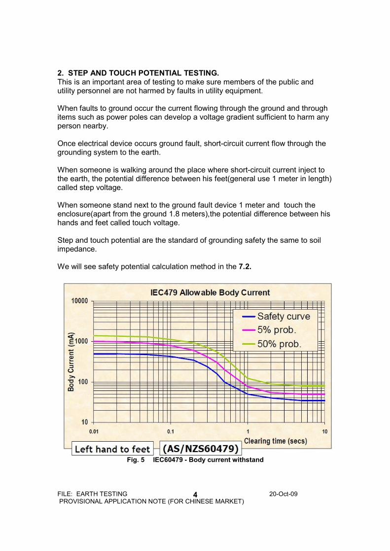
2. STEP AND TOUCH POTENTIAL TESTING. This is an important area of testing to make sure members of the public and utility personnel are not harmed by faults in utility equipment. When faults to ground occur the current flowing through the ground and through items such as power poles can develop a voltage gradient sufficient to harm any person nearby. Once electrical device occurs ground fault, short-circuit current flow through the grounding system to the earth. When someone is walking around the place where short-circuit current inject to the earth, the potential difference between his feet(general use 1 meter in length) called step voltage. When someone stand next to the ground fault device 1 meter and touch the enclosure(apart from the ground 1.8 meters),the potential difference between his hands and feet called touch voltage. Step and touch potential are the standard of grounding safety the same to soil impedance. We will see safety potential calculation method in the 7.2.
Fig. 5 IEC60479 - Body current withstand
FILE: EARTH TESTING 20-Oct-09 PROVISIONAL APPLICATION NOTE (FOR CHINESE MARKET)
5
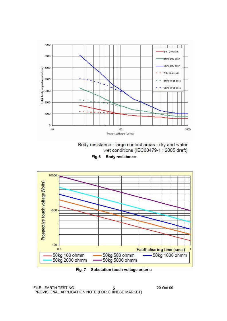
Fig.6 Body resistance
Fig. 7 Substation touch voltage criteria
FILE: EARTH TESTING 20-Oct-09 PROVISIONAL APPLICATION NOTE (FOR CHINESE MARKET)
6
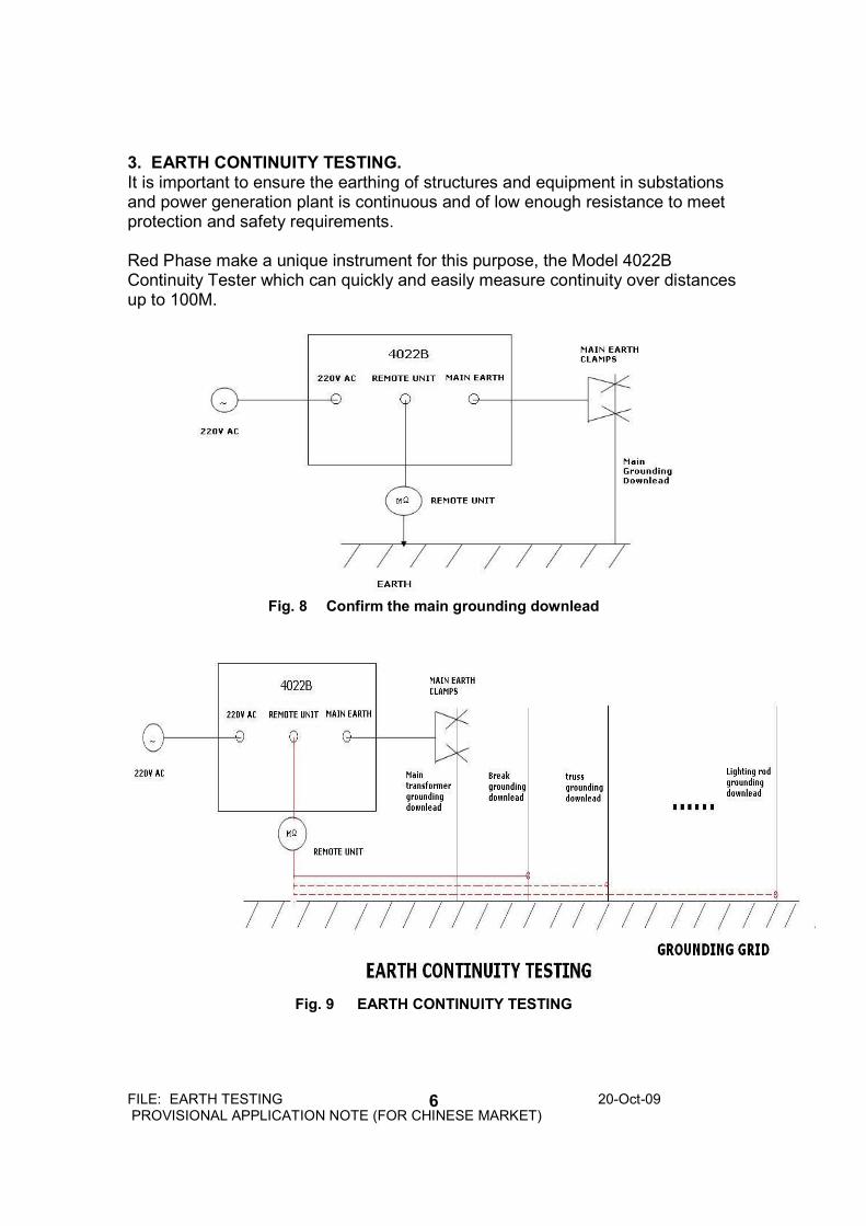
3. EARTH CONTINUITY TESTING. It is important to ensure the earthing of structures and equipment in substations and power generation plant is continuous and of low enough resistance to meet protection and safety requirements. Red Phase make a unique instrument for this purpose, the Model 4022B Continuity Tester which can quickly and easily measure continuity over distances up to 100M.
Fig. 8 Confirm the main grounding downlead
Fig. 9 EARTH CONTINUITY TESTING
FILE: EARTH TESTING 20-Oct-09 PROVISIONAL APPLICATION NOTE (FOR CHINESE MARKET)
7
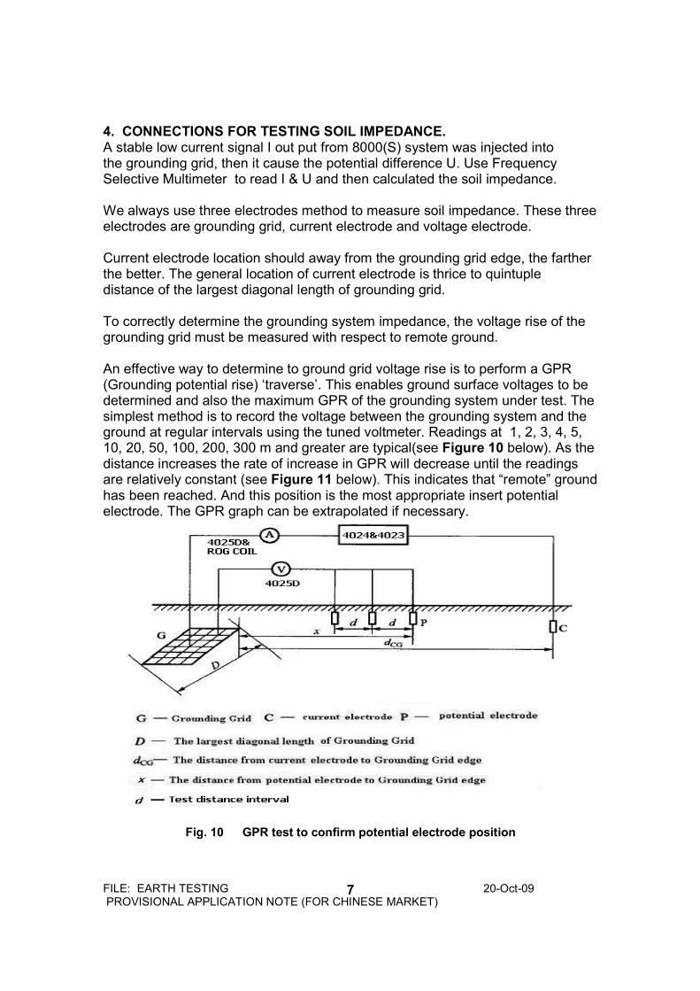
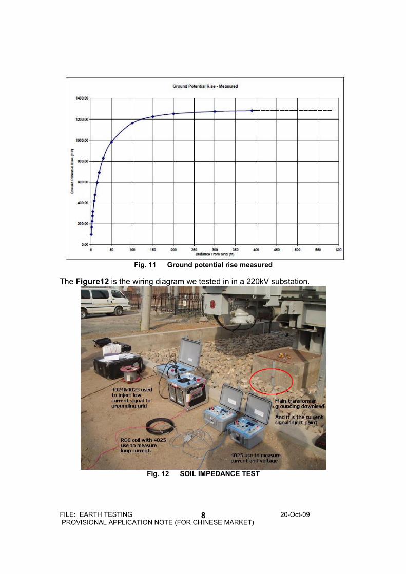
4. CONNECTIONS FOR TESTING SOIL IMPEDANCE. A stable low current signal I out put from 8000(S) system was injected into the grounding grid, then it cause the potential difference U. Use Frequency Selective Multimeter to read I & U and then calculated the soil impedance. We always use three electrodes method to measure soil impedance. These three electrodes are grounding grid, current electrode and voltage electrode. Current electrode location should away from the grounding grid edge, the farther the better. The general location of current electrode is thrice to quintuple distance of the largest diagonal length of grounding grid. To correctly determine the grounding system impedance, the voltage rise of the grounding grid must be measured with respect to remote ground. An effective way to determine to ground grid voltage rise is to perform a GPR (Grounding potential rise) ‘traverse’. This enables ground surface voltages to be determined and also the maximum GPR of the grounding system under test. The simplest method is to record the voltage between the grounding system and the ground at regular intervals using the tuned voltmeter. Readings at 1, 2, 3, 4, 5, 10, 20, 50, 100, 200, 300 m and greater are typical(see Figure 10 below). As the distance increases the rate of increase in GPR will decrease until the readings are relatively constant (see Figure 11 below). This indicates that “remote” ground has been reached. And this position is the most appropriate insert potential electrode. The GPR graph can be extrapolated if necessary.
Fig. 10 GPR test to confirm potential electrode position
FILE: EARTH TESTING 20-Oct-09 PROVISIONAL APPLICATION NOTE (FOR CHINESE MARKET)
8
Fig. 11 Ground potential rise measured
The Figure12 is the wiring diagram we tested in in a 220kV substation.
Fig. 12 SOIL IMPEDANCE TEST
FILE: EARTH TESTING 20-Oct-09 PROVISIONAL APPLICATION NOTE (FOR CHINESE MARKET)
9
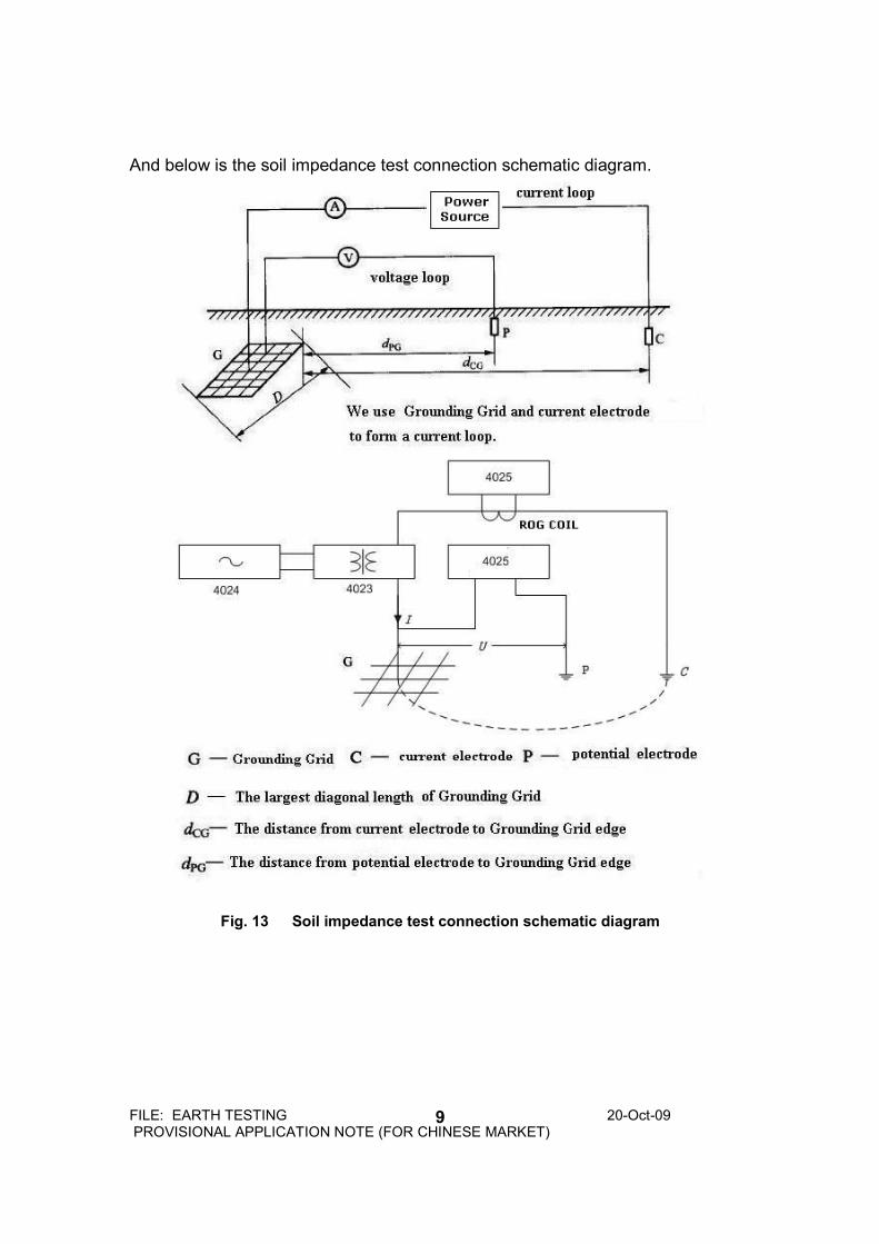
And below is the soil impedance test connection schematic diagram.
Fig. 13 Soil impedance test connection schematic diagram
FILE: EARTH TESTING 20-Oct-09 PROVISIONAL APPLICATION NOTE (FOR CHINESE MARKET)
10
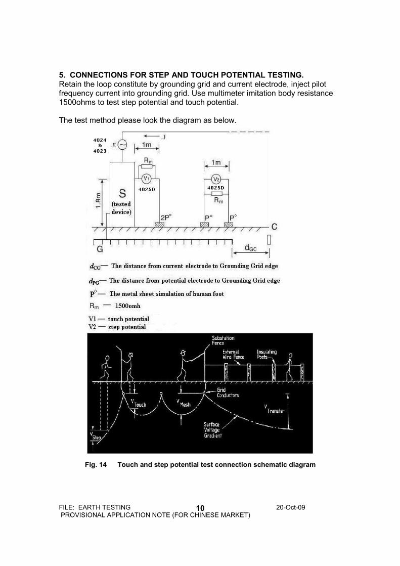
5. CONNECTIONS FOR STEP AND TOUCH POTENTIAL TESTING. Retain the loop constitute by grounding grid and current electrode, inject pilot frequency current into grounding grid. Use multimeter imitation body resistance 1500ohms to test step potential and touch potential. The test method please look the diagram as below.
Fig. 14 Touch and step potential test connection schematic diagram
FILE: EARTH TESTING 20-Oct-09 PROVISIONAL APPLICATION NOTE (FOR CHINESE MARKET)
11
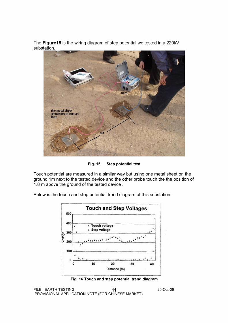
The Figure15 is the wiring diagram of step potential we tested in a 220kV substation.
Fig. 15 Step potential test
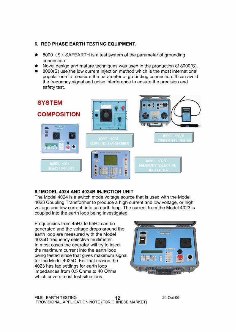
Touch potential are measured in a similar way but using one metal sheet on the ground 1m next to the tested device and the other probe touch the the position of 1.8 m above the ground of the tested device . Below is the touch and step potential trend diagram of this substation.
Fig. 16 Touch and step potential trend diagram
FILE: EARTH TESTING 20-Oct-09 PROVISIONAL APPLICATION NOTE (FOR CHINESE MARKET)
12
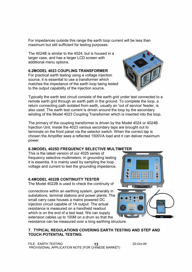
6. RED PHASE EARTH TESTING EQUIPMENT.
8000(S)SAFEARTH is a test system of the parameter of grounding
connection. Novel design and mature techniques was used in the production of 8000(S). 8000(S) use the low current injection method which is the most international
popular one to measure the parameter of grounding connection. It can avoid the frequency signal and noise interference to ensure the precision and safety test.
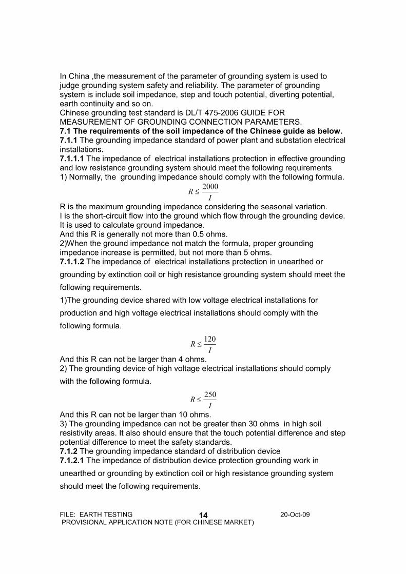
6.1MODEL 4024 AND 4024B INJECTION UNIT The Model 4024 is a switch mode voltage source that is used with the Model 4023 Coupling Transformer to produce a high current and low voltage, or high voltage and low current, into an earth loop. The current from the Model 4023 is coupled into the earth loop being investigated. Frequencies from 45Hz to 65Hz can be generated and the voltage drops around the earth loop are measured with the Model 4025D frequency selective multimeter. In most cases the operator will try to inject the maximum current into the earth loop being tested since that gives maximum signal for the Model 4025D. For that reason the 4023 has tap settings for earth loop impedances from 0.5 Ohms to 40 Ohms which covers most test situations.
FILE: EARTH TESTING 20-Oct-09 PROVISIONAL APPLICATION NOTE (FOR CHINESE MARKET)
13
For impedances outside this range the earth loop current will be less than maximum but still sufficient for testing purposes. The 4024B is similar to the 4024, but is housed in a larger case, and has a larger LCD screen with additional menu options. 6.2MODEL 4023 COUPLING TRANSFORMER For practical earth testing using a voltage injection source, it is essential to use a transformer which matches the impedance of the earth loop being tested to the output capability of the injection source. Typically the earth test circuit consists of the earth grid under test connected to a remote earth grid through an earth path in the ground. To complete the loop, a return connecting path isolated from earth, usually an 'out of service' feeder, is also used. The earth test current is driven around the loop by the secondary winding of the Model 4023 Coupling Transformer which is inserted into the loop. The primary of the coupling transformer is driven by the Model 4024 or 4024B Injection Unit. Inside the 4023 various secondary taps are brought out to terminals on the front panel via the selector switch. When the correct tap is chosen the Amplifier sees a reflected 1500VA load and it can deliver maximum power. 6.3MODEL 4025D FREQUENCY SELECTIVE MULTIMETER This is the latest version of our 4025 series of frequency selective multimeters. In grounding testing it is essentia. It is mainly used by sampling the loop voltage and current to test the grounding impedance. 6.4MODEL 4022B CONTINUITY TESTER The Model 4022B is used to check the continuity of
connections within an earthing system, generally in substations, terminal stations and power plants. The small carry case houses a mains powered DC injection circuit capable of 1A output. The actual resistance is measured on a handheld readout which is on the end of a test lead. We can supply extension cables up to 100M on a drum so that the resistance can be measured over a long earthing structure.
7. TYPICAL REGULATIONS COVERING EARTH TESTING AND STEP AND TOUCH POTENTIAL TESTING.
FILE: EARTH TESTING 20-Oct-09 PROVISIONAL APPLICATION NOTE (FOR CHINESE MARKET)
14
In China ,the measurement of the parameter of grounding system is used to judge grounding system safety and reliability. The parameter of grounding system is include soil impedance, step and touch potential, diverting potential, earth continuity and so on. Chinese grounding test standard is DL/T 475-2006 GUIDE FOR MEASUREMENT OF GROUNDING CONNECTION PARAMETERS. 7.1 The requirements of the soil impedance of the Chinese guide as below. 7.1.1 The grounding impedance standard of power plant and substation electrical installations. 7.1.1.1 The impedance of electrical installations protection in effective grounding and low resistance grounding system should meet the following requirements 1) Normally, the grounding impedance should comply with the following formula.
IR
2000≤
R is the maximum grounding impedance considering the seasonal variation. I is the short-circuit flow into the ground which flow through the grounding device. It is used to calculate ground impedance. And this R is generally not more than 0.5 ohms. 2)When the ground impedance not match the formula, proper grounding impedance increase is permitted, but not more than 5 ohms. 7.1.1.2 The impedance of electrical installations protection in unearthed or
grounding by extinction coil or high resistance grounding system should meet the
following requirements.
1)The grounding device shared with low voltage electrical installations for
production and high voltage electrical installations should comply with the
following formula.
IR
120≤
And this R can not be larger than 4 ohms. 2) The grounding device of high voltage electrical installations should comply
with the following formula.
IR
250≤
And this R can not be larger than 10 ohms. 3) The grounding impedance can not be greater than 30 ohms in high soil resistivity areas. It also should ensure that the touch potential difference and step potential difference to meet the safety standards. 7.1.2 The grounding impedance standard of distribution device 7.1.2.1 The impedance of distribution device protection grounding work in
unearthed or grounding by extinction coil or high resistance grounding system
should meet the following requirements.
FILE: EARTH TESTING 20-Oct-09 PROVISIONAL APPLICATION NOTE (FOR CHINESE MARKET)
15
1)When distribution transformer installed outside the building, R should comply
with the following formula.
IR
50≤
And this R can not be larger than 4 ohms. When distribution transformer installed in the building, R still can not be larger than 4 ohms. 7.1.2.2 Other distribution device grounding impedance should meet the formula
IR
2000≤
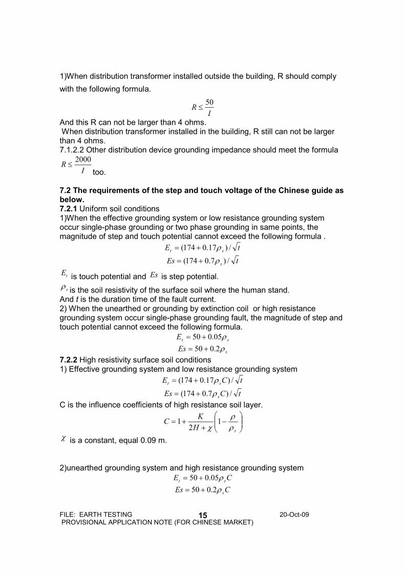
too. 7.2 The requirements of the step and touch voltage of the Chinese guide as below. 7.2.1 Uniform soil conditions 1)When the effective grounding system or low resistance grounding system occur single-phase grounding or two phase grounding in same points, the magnitude of step and touch potential cannot exceed the following formula .
tEst/)17.0174( ρ+=
tEs
s/)7.0174( ρ+=
tE
is touch potential and Es is step potential.
sρ
is the soil resistivity of the surface soil where the human stand. And t is the duration time of the fault current. 2) When the unearthed or grounding by extinction coil or high resistance grounding system occur single-phase grounding fault, the magnitude of step and touch potential cannot exceed the following formula.
stE ρ05.050 +=
sEs ρ2.050 +=
7.2.2 High resistivity surface soil conditions 1) Effective grounding system and low resistance grounding system
tCEst/)17.0174( ρ+=
tCEss/)7.0174( ρ+=
C is the influence coefficients of high resistance soil layer.
−
++=
sH
KC
ρρ
χ1
21
χ is a constant, equal 0.09 m. 2)unearthed grounding system and high resistance grounding system
CEst
ρ05.050 +=
CEss
ρ2.050 +=
FILE: EARTH TESTING 20-Oct-09 PROVISIONAL APPLICATION NOTE (FOR CHINESE MARKET)
16
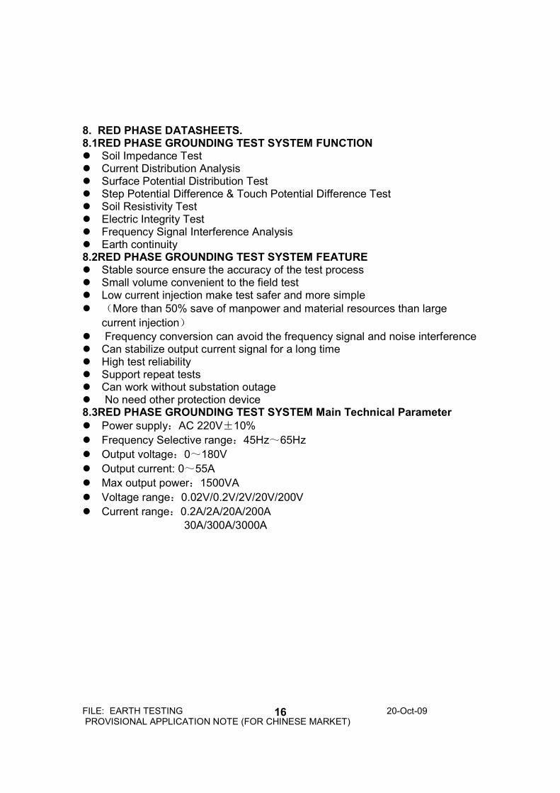
8. RED PHASE DATASHEETS. 8.1RED PHASE GROUNDING TEST SYSTEM FUNCTION Soil Impedance Test Current Distribution Analysis Surface Potential Distribution Test Step Potential Difference & Touch Potential Difference Test Soil Resistivity Test Electric Integrity Test Frequency Signal Interference Analysis Earth continuity 8.2RED PHASE GROUNDING TEST SYSTEM FEATURE Stable source ensure the accuracy of the test process Small volume convenient to the field test Low current injection make test safer and more simple
(More than 50% save of manpower and material resources than large
current injection)
Frequency conversion can avoid the frequency signal and noise interference Can stabilize output current signal for a long time High test reliability Support repeat tests Can work without substation outage No need other protection device 8.3RED PHASE GROUNDING TEST SYSTEM Main Technical Parameter
Power supply:AC 220V±10%
Frequency Selective range:45Hz~65Hz
Output voltage:0~180V
Output current: 0~55A
Max output power:1500VA
Voltage range:0.02V/0.2V/2V/20V/200V
Current range:0.2A/2A/20A/200A
30A/300A/3000A