Embed Size (px)
DESCRIPTION
Earth Science Applications of Space Based Geodesy DES-7355 Tu-Th 9:40-11:05 Seminar Room in 3892 Central Ave. (Long building) Bob Smalley Office: 3892 Central Ave, Room 103 678-4929 Office Hours – Wed 14:00-16:00 or if I’m in my office. - PowerPoint PPT Presentation
Citation preview
Earth Science Applications of Space Based GeodesyDES-7355
Tu-Th 9:40-11:05Seminar Room in 3892 Central Ave. (Long
building)
Bob SmalleyOffice: 3892 Central Ave, Room 103
678-4929Office Hours – Wed 14:00-16:00 or if I’m in
my office.http://www.ceri.memphis.edu/people/smalley/ESCI7355/ESCI_7355_Applications_of_Space_Based_Geodesy.html
Class 5
1
2http://www.unav-micro.com/about_gps.htm
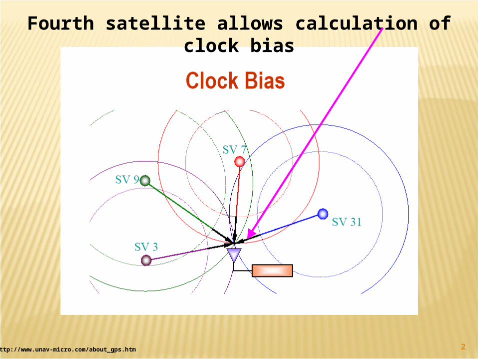
Fourth satellite allows calculation of clock bias
3
now that we have precise clocks……how do we know when the signals
left the satellite?
this is where the designers of GPS were clever…
…synchronize satellite and receiver sothey are generating same code at
same timeWe will look at this in more detail later
step 3: getting perfect timing
Mattioli-http://comp.uark.edu/~mattioli/geol_4733.html and Trimble
4
finally… step 4: knowing where a satellite is in space
Satellites in known orbits
Orbits programmed into receivers
Satellites constantly monitored by DoD …identify errors (ephemeris errors) in
orbits …usually minor
Corrections relayed back to satellite
Satellite transmits Mattioli-http://comp.uark.edu/~mattioli/geol_4733.html and Trimble
5
Orbital data (ephemeris) is embedded in the satellite data message
Ephemeris data contains parameters that describe the elliptical path of the satellite
Receiver uses this data to calculate the position of the satellite (x,y,z)
step 4: knowing where a satellite is in space
http://www.unav-micro.com/about_gps.htm
6http://www.colorado.edu/engineering/ASEN/asen5090/asen5090.html
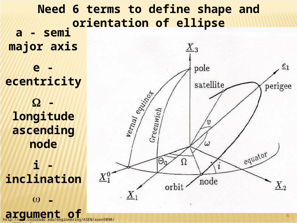
a - semi major axis
e - ecentricity
- longitude ascending
nodei -
inclination -
argument of perigee - true
anomaly
Need 6 terms to define shape and orientation of ellipse
7
step 5: identifying errors
Will do later
8
24 operational space vehicles (“SV’s”)
6 orbit planes, 4 SV’s/Plane Plus at least 3 in-orbit spares
Orbit characteristics:
Altitude: 20,180 km (SMA = 26558 km) Inclination: 550
A. Ganse, U. Washington , http://staff.washington.edu/aganse/
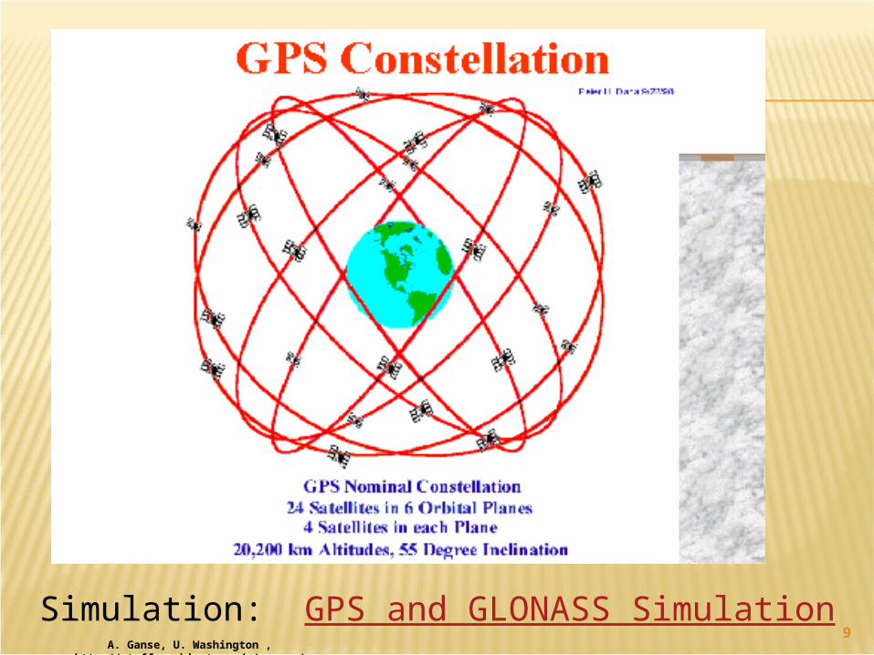
9Simulation: GPS and GLONASS Simulation
A. Ganse, U. Washington , http://staff.washington.edu/aganse/
10
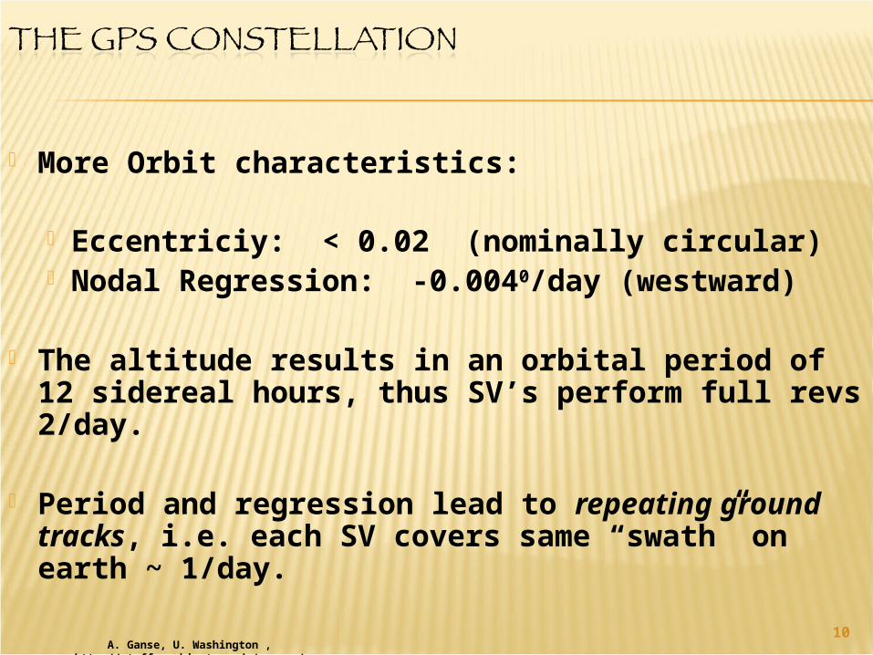
More Orbit characteristics:
Eccentriciy: < 0.02 (nominally circular) Nodal Regression: -0.0040/day (westward)
The altitude results in an orbital period of 12 sidereal hours, thus SV’s perform full revs 2/day.
Period and regression lead to repeating ground tracks, i.e. each SV covers same “swath” on earth ~ 1/day.
A. Ganse, U. Washington , http://staff.washington.edu/aganse/
11From J. HOW, MIT
12
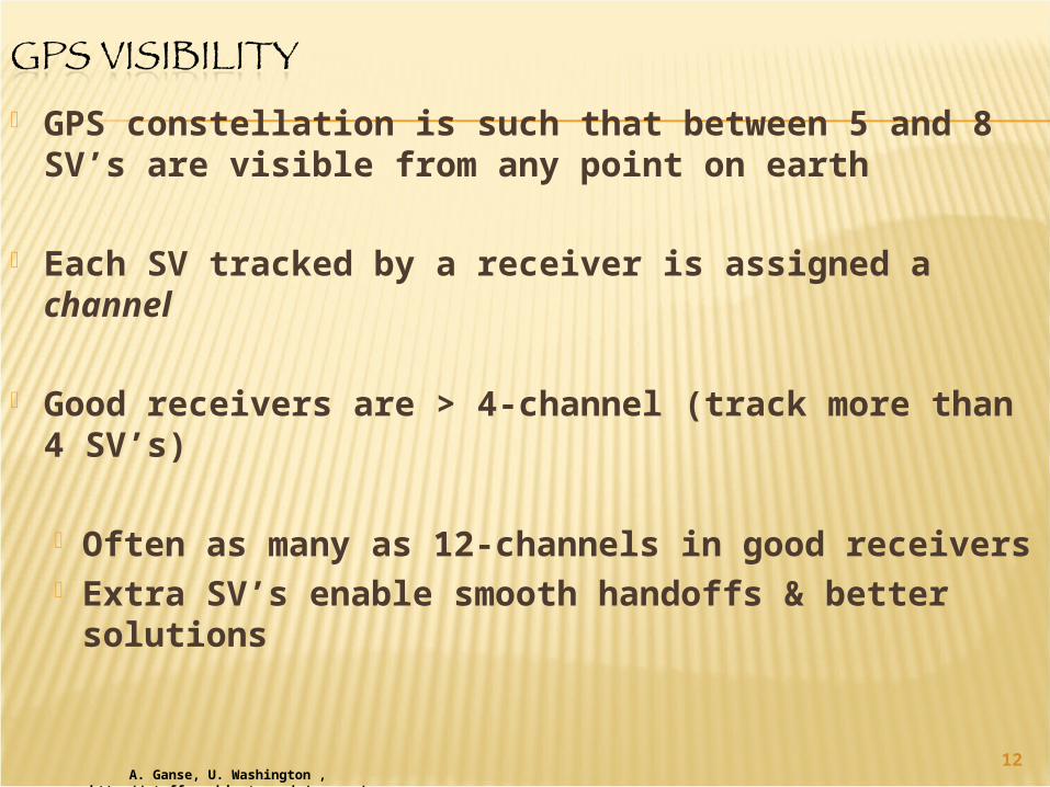
GPS constellation is such that between 5 and 8 SV’s are visible from any point on earth
Each SV tracked by a receiver is assigned a channel
Good receivers are > 4-channel (track more than 4 SV’s)
Often as many as 12-channels in good receivers Extra SV’s enable smooth handoffs & better
solutions
A. Ganse, U. Washington , http://staff.washington.edu/aganse/
13
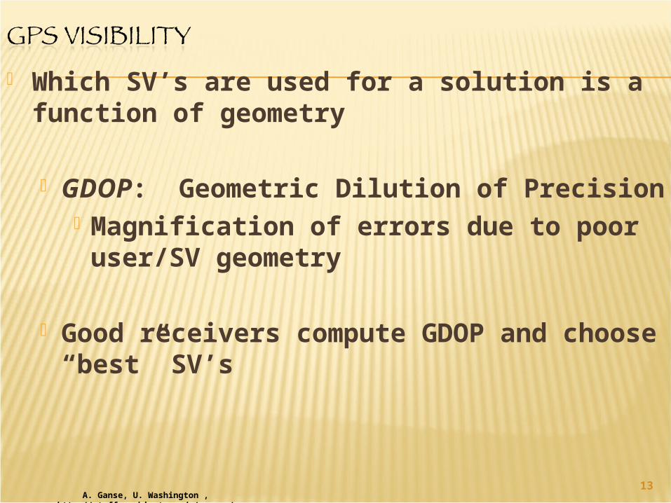
Which SV’s are used for a solution is a function of geometry
GDOP: Geometric Dilution of Precision Magnification of errors due to poor user/SV geometry
Good receivers compute GDOP and choose “best” SV’s
A. Ganse, U. Washington , http://staff.washington.edu/aganse/
14
Accuracy of position is only as good as your clock
To know where you are, you must know when you are
Receiver clock must match SV clock to compute delta-T
A. Ganse, U. Washington , http://staff.washington.edu/aganse/
15
SVs carry atomic oscillators (2 rubidium, 2 cesium each)
Not practical for hand-held receiver
A. Ganse, U. Washington , http://staff.washington.edu/aganse/
16
Accumulated drift of receiver clock is called clock bias
The erroneously measured range is called a pseudorange
To eliminate the bias, a 4th SV is tracked 4 equations, 4 unknowns Solution now generates X,Y,Z and b
If Doppler also tracked, Velocity can be computed
A. Ganse, U. Washington , http://staff.washington.edu/aganse/
17A. Ganse, U. Washington ,
http://staff.washington.edu/aganse/
GPS Time
GPS time is referenced to 6 January 1980, 00:00:00
GPS uses a week/time-into-week format
Jan 6 = First Sunday in 1980
18A. Ganse, U. Washington ,
http://staff.washington.edu/aganse/
GPS Time
GPS satellite clocks are essentially synched to International Atomic Time (TAI) (and
therefore to UTC)
Ensemble of atomic clocks which provide international timing standards.
TAI is the basis for Coordinated Universal Time (UTC), used for most civil
timekeeping
GPS time = TAI - 15sSince 15 positive leap seconds since
1/6/1980
19Mod from - A. Ganse, U. Washington , http://staff.washington.edu/aganse/,
http://www.eomonline.com/Common/Archives/1996jan/96jan_gps.html
GPS Time
GPS time is different than GMT because GMT is continuously adjusted for Earth rotation and translation charges with respect to the sun and other celestial
reference bodies.
GPS time shifts with respect to UTC as UTCis adjusted using positive or negative “leap” seconds to accommodate earth’s
slowing, etc.
GPS time is not adjusted for celestial phenomena since it is based on the
behavior of atomic clocks monitoring the satellite system.
20A. Ganse, U. Washington ,
http://staff.washington.edu/aganse/
More About Time
GPS system time referenced to Master USNO Clock, but now implements its own
“composite clock”
SV clocks good to about 1 part in 1013
Delta between GPS SV time & UTC is included in nav/timing message
21A. Ganse, U. Washington ,
http://staff.washington.edu/aganse/
More About Time
Correction terms permit user to determine UTC to better than 90 nanoseconds (~10-7
sec)
The most effective time transfer mechanism anywhere
22A. Ganse, U. Washington , http://staff.washington.edu/aganse/,
Klein thesis ch 3
More About Time
Satellite velocity induces special relativistic time dilation of about -7.2 sec/day
General relativistic gravitational frequency shift causes about 45.6 sec/day
For a total 38.4 sec/day
GPS clocks tuned to 10.22999999545 Mhz
(1 sec -> 300 m, build up 1 sec in 38 minutes if don’t correct!)
23A. Ganse, U. Washington , http://staff.washington.edu/aganse/,
Klein thesis ch 3
More About Time
The 10-bit GPS-week field in the data “rolled-over” on August 21/22 1999 – some
receivers probably failed!
24A. Ganse, U. Washington ,
http://staff.washington.edu/aganse/
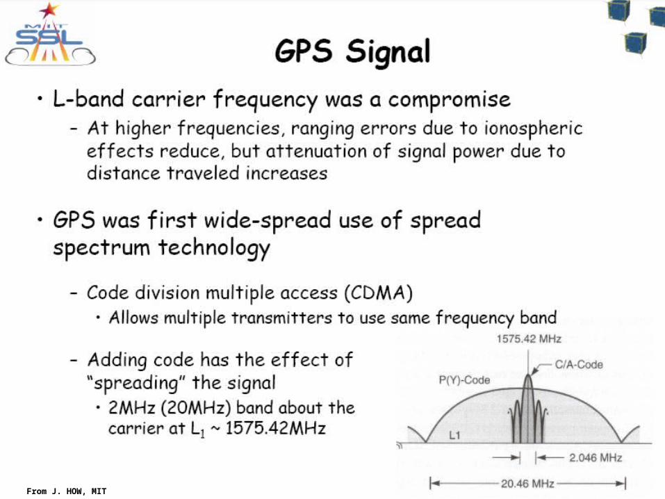
GPS Signals
GPS signals are broadcast on 2 L-band carriers
L1: 1575.42 MHzModulated by C/A-code & P-code
(codes covered later)
L2: 1227.6 MHzModulated by P-code only
(3rd carrier, L3, used for nuclear explosion detection)
25A. Ganse, U. Washington ,
http://staff.washington.edu/aganse/
GPS Signals
Most unsophisticated receivers only track L1
If L2 tracked, then the phase difference (L1-L2) can be used to filter out ionospheric
delay.
This is true even if the receiver cannot decrypt the P-code (more later)
L1-only receivers use a simplified correction model
26A. Ganse, U. Washington ,
http://staff.washington.edu/aganse/
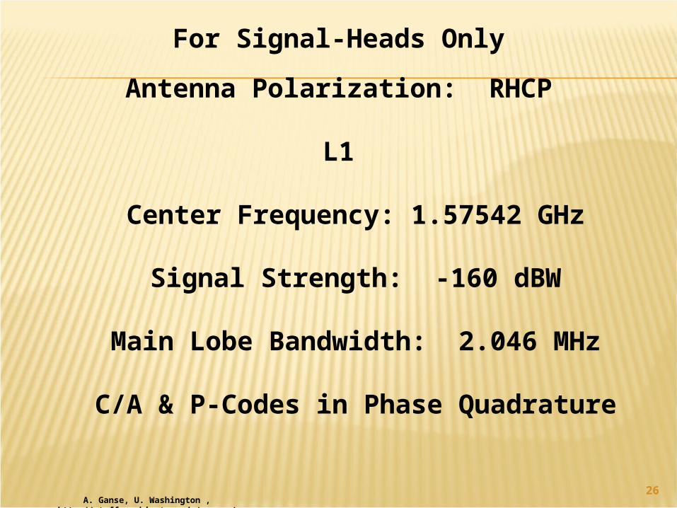
For Signal-Heads OnlyAntenna Polarization: RHCP
L1
Center Frequency: 1.57542 GHz
Signal Strength: -160 dBW
Main Lobe Bandwidth: 2.046 MHz
C/A & P-Codes in Phase Quadrature
27A. Ganse, U. Washington ,
http://staff.washington.edu/aganse/
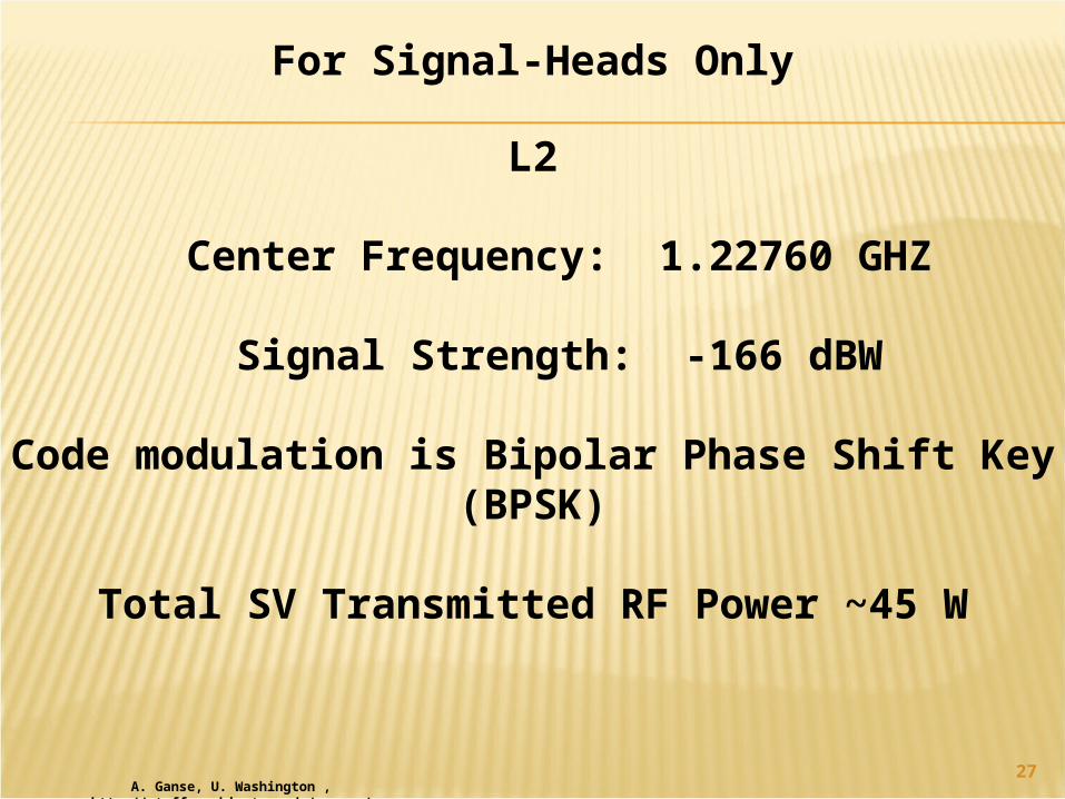
For Signal-Heads Only
L2
Center Frequency: 1.22760 GHZ
Signal Strength: -166 dBW
Code modulation is Bipolar Phase Shift Key (BPSK)
Total SV Transmitted RF Power ~45 W
28
29
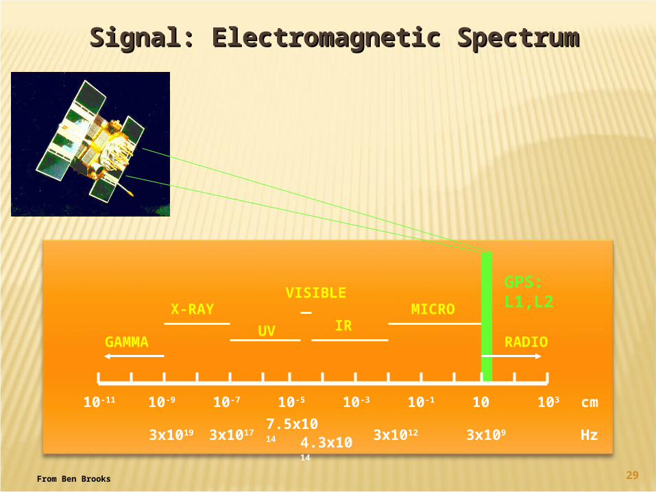
10-11 10-9 10-7 10-5 10-3 10-1 10 103
GAMMA
X-RAYUV
VISIBLE
IRMICRO
cm
4.3x10¹⁴
3x101
23x109 Hz7.5x10
143x10173x1019
RADIO
GPS: L1,L2
Signal: Electromagnetic SpectrumSignal: Electromagnetic Spectrum
From Ben Brooks
30From J. HOW, MIT
31http://www.colorado.edu/engineering/ASEN/asen5090/asen5090.html
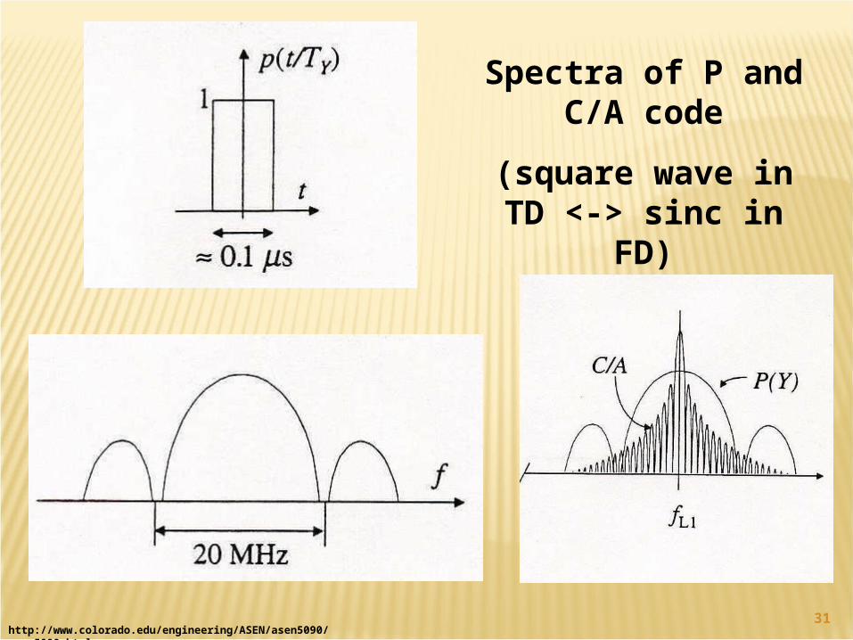
Spectra of P and C/A code
(square wave in TD <-> sinc in FD)
32http://www.ieee.org/organizations/history_center/cht_papers/SpreadSpectrum.pdf
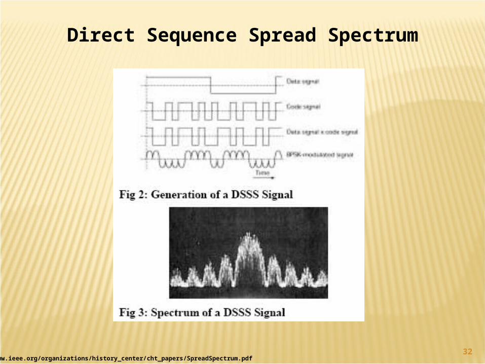
Direct Sequence Spread Spectrum