Embed Size (px)
Citation preview
Earth’s field effect on magnetic performance of horizontally and verticallypolarizing undulators
N. O. Strelnikov1,2,* and I. B. Vasserman1,†1Advanced Photon Source, Argonne National Laboratory, Argonne, Illinois 60439, USA
2Budker Institute of Nuclear Physics, Novosibirsk 630090, Russia(Received 9 December 2013; published 11 June 2014)
Effects of the interaction of the Earth’s magnetic field with different types of insertion devices (IDs) werestudied at the Advanced Photon Source (APS) at Argonne National Laboratory (Argonne) according to theimprovement of high-precision field measurements and field correction techniques that should meet thetight requirements for next-generation x-ray sources. The magnetic measurements of two Advanced PhotonSource hybrid-type IDs with periods of 33 and 27 mm have been performed. The impact of different designelements was considered. It was demonstrated that the specified limits for IDs can be exceeded if the effectof the Earth’s field is not taken into account for various orientations of the IDs in the storage ring.Numerical simulations were done to better interpret experimental results for both devices and to estimatethe effect for novel ID with the horizontal main field, which is now under development.
DOI: 10.1103/PhysRevSTAB.17.062401 PACS numbers: 07.55.Db, 07.85.Qe, 41.60.Ap
I. INTRODUCTION
The magnetic performance of undulators at third-gen-eration synchrotron radiation (SR) sources has been studiedand improved significantly over the past decade [1–3].Undulators have delivered predicted bright radiation beamsand at the same time have met requirements to be trans-parent to the electron beam in storage rings. These require-ments directly depend on the emittance of the storage ring[4], and with new designs of diffraction-limited x-ray SRsources it is important to identify and mitigate all possiblee-beam perturbations caused by insertion devices (IDs).One such perturbation is related to the fact that IDs aretypically prepared and tuned in a magnetic environmentthat could differ from the operational one. Specifically, theorientation of the ID’s magnetic structure and its frame withrespect to the vector of the Earth’s magnetic field at thelocation of ID magnetic measurement bench in AdvancedPhoton Source (APS) Magnetic Measurement Facility(MMF) differs from those at many straight sections ofthe Argonne National Laboratory’s (Argonne’s) APS stor-age ring. Such variations lead to differences in thepenetration of the Earth’s magnetic field in the ID gapspace, as well as differences in interactions of that field withmagnetically susceptible elements of ID mechanical struc-tures. An accurate assessment of the influence the Earth’smagnetic field has on values and variations of an ID’s field
integrals for different magnetic gaps is important for any IDinstalled in the storage ring. However, this is even moresignificant for future SR diffraction-limited sources. Suchsources with ultralow emittance will utilize on-axis e-beaminjection and, as a result, new types of IDs with horizontalmain magnetic fields could become as common as currentlystandard IDs with main vertical fields. Therefore, theinfluence of the Earth’s magnetic field on the magneticperformance of different types of IDs in different orienta-tions has to be evaluated. Some consideration of this taskhas already been done [5,6]. This paper presents exper-imental and modeling results concerning the effects of theinteraction of Earth’s magnetic field with different types ofIDs. For experimental studies, two APS hybrid-type IDswith periods of 33 and 27 mm were used.
II. MEASUREMENTS OF THE EFFECTS OF THEEARTH’S FIELD PROPAGATION IN THE ID GAP
Although the absolute value of the Earth’s magnetic fieldis much smaller than the main field inside the ID’s gap, theEarth’s field contribution to integrals and multipole com-ponents, both vertical and horizontal, on the ID lengthcould be quite significant and even exceed specificationrequirements. The requirements for the APS insertiondevices were set by the APS team. These requirementsresult from the need to provide beam stability at 10% ofparticle beam emittance [7]. Usually, tuning of the devicesincludes the Earth field at the APS Magnetic MeasurementFacility (MMF), and the propagation of the field and itseffect on the field integrals and multipole components areassumed to remain the same during operation. Recently itwas revealed that Earth field propagation is affected ratherstrongly by the orientation of the device, and that this effectcan cause distortions when tuning the device according to
*[email protected]†[email protected]
Published by the American Physical Society under the terms ofthe Creative Commons Attribution 3.0 License. Further distri-bution of this work must maintain attribution to the author(s) andthe published article’s title, journal citation, and DOI.
PHYSICAL REVIEW SPECIAL TOPICS - ACCELERATORS AND BEAMS 17, 062401 (2014)
1098-4402=14=17(6)=062401(10) 062401-1 Published by the American Physical Society
specifications in the MMF. An improved storage ringfeedback system currently allows these errors to becorrected; however, future APS upgrades will assumehorizontal emittance that decreases by almost 2 orders ofmagnitude, so the requirements for beam stability willbecome much tighter.Appendix A contains a description of the ID’s field
integrals and their effect on the charged particle beampassing the ID. The vertical component of Earth’s magneticfield introduces an orientation-independent addition to thefield integrals for both types of IDs, with a vertical orhorizontal main magnetic field. The influence of thehorizontal component of Earth’s magnetic field on theID’s horizontal field (transverse to the ID’s longitudinalaxis) depends on the orientation of the ID in the storage ringtunnel. This is the case for both types of ID with verticaland horizontal main magnetic field. As a result, the valuesof the transverse horizontal field integrals of such IDs in thestorage ring tunnel could differ from those measured atthe Magnet Measurement Facility (MMF) of the APS. Theinput of the Earth’s horizontal field component on the ID’stransverse horizontal field integral also depends on the ID’sgap (Appendix B), as well as the material and geometry ofthe ID support and drive frame. All these gap- and position-dependent effects in addition to the potential influence ofthe ID’s frame on the ID’s field integrals can and should bestudied experimentally by using different types of APS IDsand utilizing precise measurement techniques at theAPS MMF.Only one of the two components of the horizontal part of
the Earth’s magnetic field can contribute to the ID fieldintegral: the component perpendicular to the longitudinalaxis of the ID. Therefore, only that component will beconsidered in further analysis. A simple way to measure thefield integral of the transverse horizontal component of theEarth’s field is to measure ID field integrals for two IDorientations that differ by 180° rotation around the verticalaxis (the y axis). In this case,J1xð0Þ ¼ J1xU þ J1xE—first field integral of the hori-
zontal field, original orientation,J1xð180Þ ¼ −J1xU þ J1xE—first field integral, rotated
180° around the y axis.Here, J1xU is the undulator magnetic structure contribu-
tion, and J1xE is the Earth’s field contribution. It followsfrom these equations that J1xE ¼ ½J1xð0°Þ þ J1xð180°Þ�=2.Two APS IDs, APS27 #5s and UNA33 #6, which have
27-mm and 33-mm periods, respectively, have been chosenfor the measurements performed at the APS MMF. Theframe of the APS27 #5s is made of steel, which could bemagnetized; the frame of the UNA33 #6 is practicallynonmagnetic. Therefore, comparing measurements forthese two devices should reveal the effect of the ID frameon the field integrals. In addition, preliminary measure-ments without IDs have been performed to define theEarth’s field value at the measurement area.
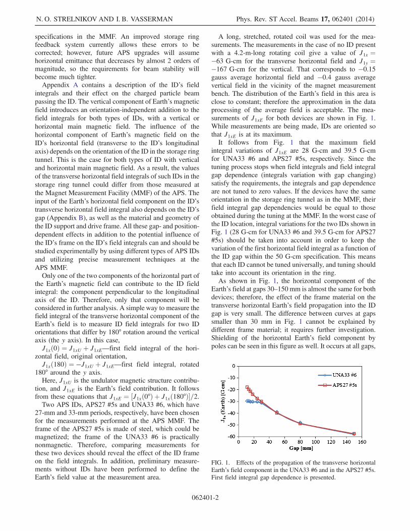
A long, stretched, rotated coil was used for the mea-surements. The measurements in the case of no ID presentwith a 4.2-m-long rotating coil give a value of J1x ¼−63 G-cm for the transverse horizontal field and J1y ¼−167 G-cm for the vertical. That corresponds to −0.15gauss average horizontal field and −0.4 gauss averagevertical field in the vicinity of the magnet measurementbench. The distribution of the Earth’s field in this area isclose to constant; therefore the approximation in the dataprocessing of the average field is acceptable. The mea-surements of J1xE for both devices are shown in Fig. 1.While measurements are being made, IDs are oriented sothat J1xE is at its maximum.It follows from Fig. 1 that the maximum field
integral variations of J1xE are 28 G-cm and 39.5 G-cmfor UNA33 #6 and APS27 #5s, respectively. Since thetuning process stops when field integrals and field integralgap dependence (integrals variation with gap changing)satisfy the requirements, the integrals and gap dependenceare not tuned to zero values. If the devices have the sameorientation in the storage ring tunnel as in the MMF, theirfield integral gap dependencies would be equal to thoseobtained during the tuning at the MMF. In the worst case ofthe ID location, integral variations for the two IDs shown inFig. 1 (28 G-cm for UNA33 #6 and 39.5 G-cm for APS27#5s) should be taken into account in order to keep thevariation of the first horizontal field integral as a function ofthe ID gap within the 50 G-cm specification. This meansthat each ID cannot be tuned universally, and tuning shouldtake into account its orientation in the ring.As shown in Fig. 1, the horizontal component of the
Earth’s field at gaps 30–150 mm is almost the same for bothdevices; therefore, the effect of the frame material on thetransverse horizontal Earth’s field propagation into the IDgap is very small. The difference between curves at gapssmaller than 30 mm in Fig. 1 cannot be explained bydifferent frame material; it requires further investigation.Shielding of the horizontal Earth’s field component bypoles can be seen in this figure as well. It occurs at all gaps,
FIG. 1. Effects of the propagation of the transverse horizontalEarth’s field component in the UNA33 #6 and in the APS27 #5s.First field integral gap dependence is presented.
N. O. STRELNIKOV AND I. B. VASSERMAN Phys. Rev. ST Accel. Beams 17, 062401 (2014)
062401-2
even in the biggest gap: the field integral measured in the150-mm gap is −57.5 G-cm, and the same integral mea-sured without devices is −63 5 G-cm.
III. VERTICAL EARTH’S FIELD PROPAGATION
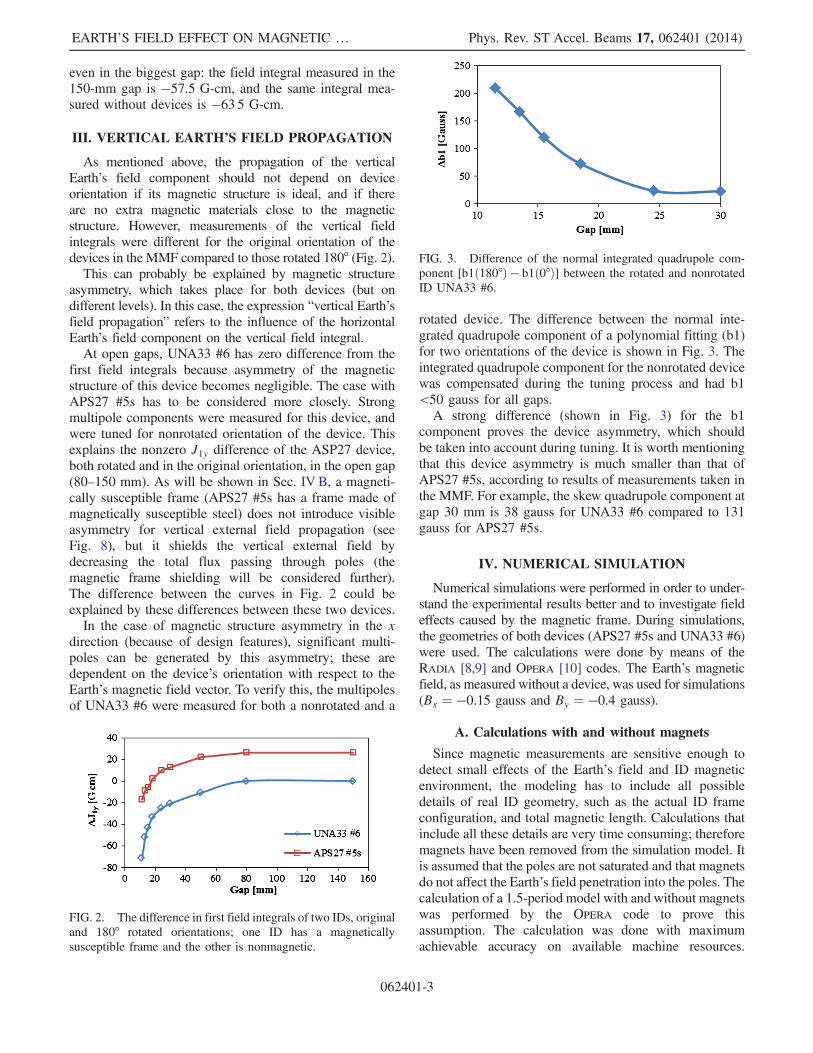
As mentioned above, the propagation of the verticalEarth’s field component should not depend on deviceorientation if its magnetic structure is ideal, and if thereare no extra magnetic materials close to the magneticstructure. However, measurements of the vertical fieldintegrals were different for the original orientation of thedevices in the MMF compared to those rotated 180° (Fig. 2).This can probably be explained by magnetic structure
asymmetry, which takes place for both devices (but ondifferent levels). In this case, the expression “vertical Earth’sfield propagation” refers to the influence of the horizontalEarth’s field component on the vertical field integral.At open gaps, UNA33 #6 has zero difference from the
first field integrals because asymmetry of the magneticstructure of this device becomes negligible. The case withAPS27 #5s has to be considered more closely. Strongmultipole components were measured for this device, andwere tuned for nonrotated orientation of the device. Thisexplains the nonzero J1y difference of the ASP27 device,both rotated and in the original orientation, in the open gap(80–150 mm). As will be shown in Sec. IV B, a magneti-cally susceptible frame (APS27 #5s has a frame made ofmagnetically susceptible steel) does not introduce visibleasymmetry for vertical external field propagation (seeFig. 8), but it shields the vertical external field bydecreasing the total flux passing through poles (themagnetic frame shielding will be considered further).The difference between the curves in Fig. 2 could beexplained by these differences between these two devices.In the case of magnetic structure asymmetry in the x
direction (because of design features), significant multi-poles can be generated by this asymmetry; these aredependent on the device’s orientation with respect to theEarth’s magnetic field vector. To verify this, the multipolesof UNA33 #6 were measured for both a nonrotated and a
rotated device. The difference between the normal inte-grated quadrupole component of a polynomial fitting (b1)for two orientations of the device is shown in Fig. 3. Theintegrated quadrupole component for the nonrotated devicewas compensated during the tuning process and had b1<50 gauss for all gaps.A strong difference (shown in Fig. 3) for the b1
component proves the device asymmetry, which shouldbe taken into account during tuning. It is worth mentioningthat this device asymmetry is much smaller than that ofAPS27 #5s, according to results of measurements taken inthe MMF. For example, the skew quadrupole component atgap 30 mm is 38 gauss for UNA33 #6 compared to 131gauss for APS27 #5s.
IV. NUMERICAL SIMULATION
Numerical simulations were performed in order to under-stand the experimental results better and to investigate fieldeffects caused by the magnetic frame. During simulations,the geometries of both devices (APS27 #5s and UNA33 #6)were used. The calculations were done by means of theRADIA [8,9] and OPERA [10] codes. The Earth’s magneticfield, as measured without a device, was used for simulations(Bx ¼ −0.15 gauss and By ¼ −0.4 gauss).
A. Calculations with and without magnets
Since magnetic measurements are sensitive enough todetect small effects of the Earth’s field and ID magneticenvironment, the modeling has to include all possibledetails of real ID geometry, such as the actual ID frameconfiguration, and total magnetic length. Calculations thatinclude all these details are very time consuming; thereforemagnets have been removed from the simulation model. Itis assumed that the poles are not saturated and that magnetsdo not affect the Earth’s field penetration into the poles. Thecalculation of a 1.5-period model with and without magnetswas performed by the OPERA code to prove thisassumption. The calculation was done with maximumachievable accuracy on available machine resources.
FIG. 2. The difference in first field integrals of two IDs, originaland 180° rotated orientations; one ID has a magneticallysusceptible frame and the other is nonmagnetic.
FIG. 3. Difference of the normal integrated quadrupole com-ponent [b1ð180°Þ − b1ð0°Þ] between the rotated and nonrotatedID UNA33 #6.
EARTH’S FIELD EFFECT ON MAGNETIC … Phys. Rev. ST Accel. Beams 17, 062401 (2014)
062401-3
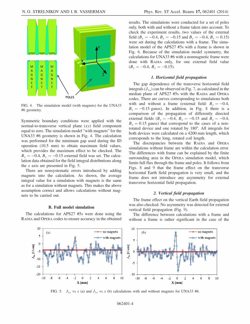
Symmetric boundary conditions were applied with thenormal-to-transverse vertical plane (xy) field componentequal to zero. The simulation model “with magnets” for theUNA33 #6 geometry is shown in Fig. 4. The calculationwas performed for the minimum gap used during the IDoperation (10.5 mm) to obtain maximum field values,which provides the maximum effect to be checked. TheBy ¼ −0.4, Bx ¼ −0.15 external field was set. The calcu-lation data obtained for the field integral distributions alongthe x axis are presented in Fig. 5.There are nonsystematic errors introduced by adding
magnets into the calculation. As shown, the averageintegral value for a simulation with magnets is the sameas for a simulation without magnets. This makes the aboveassumption correct and allows calculations without mag-nets to be carried out.
B. Full model simulation
The calculations for APS27 #5s were done using theRADIA and OPERA codes to ensure accuracy in the obtained
results. The simulations were conducted for a set of polesonly, both with and without a frame taken into account. Tocheck the experiment results, two values of the externalfield (By ¼ −0.4, Bx ¼ −0.15 and By ¼ −0.4, Bx ¼ 0.15)were set during the calculations with a frame. The simu-lation model of the APS27 #5s with a frame is shown inFig. 6. Because of the simulation model symmetry, thecalculations for UNA33 #6 with a nonmagnetic frame weredone with RADIA only, for one external field value(By ¼ −0.4, Bx ¼ −0.15).
1. Horizontal field propagation
The gap dependence of the transverse horizontal fieldintegrals (J1x) can be observed in Fig. 7, as calculated in themedian plane of APS27 #5s with the RADIA and OPERA
codes. There are curves corresponding to simulations bothwith and without a frame (external field: By ¼ −0.4,Bx ¼ −0.15 gauss). In addition, in Fig. 8 there is acomparison of the propagation of differently directedexternal fields (By ¼ −0.4, Bx ¼ −0.15 and By ¼ −0.4,Bx ¼ 0.15 gauss) that correspond to the cases of a non-rotated device and one rotated by 180°. All integrals forboth devices were calculated on a 4200-mm length, whichcorresponds to the long, rotated coil length.The discrepancies between the RADIA and OPERA
simulations without frame are within the calculation error.The differences with frame can be explained by the finitesurrounding area in the OPERA simulation model, whichlimits full flux through the frame and poles. It follows fromFigs. 8 and 9 that the frame effect on the transversehorizontal Earth field propagation is very small, and theframe does not introduce any asymmetry for externaltransverse horizontal field propagation.
2. Vertical field propagation
The frame effect on the vertical Earth field propagationwas also checked. No asymmetry was detected for externalvertical field propagation (Fig. 9).The difference between calculations with a frame and
without a frame is rather significant in the case of the
FIG. 4. The simulation model (with magnets) for the UNA33#6 geometry.
FIG. 5. J1y vs x (a) and J1x vs x (b) calculations with and without magnets for UNA33 #6.
N. O. STRELNIKOV AND I. B. VASSERMAN Phys. Rev. ST Accel. Beams 17, 062401 (2014)
062401-4
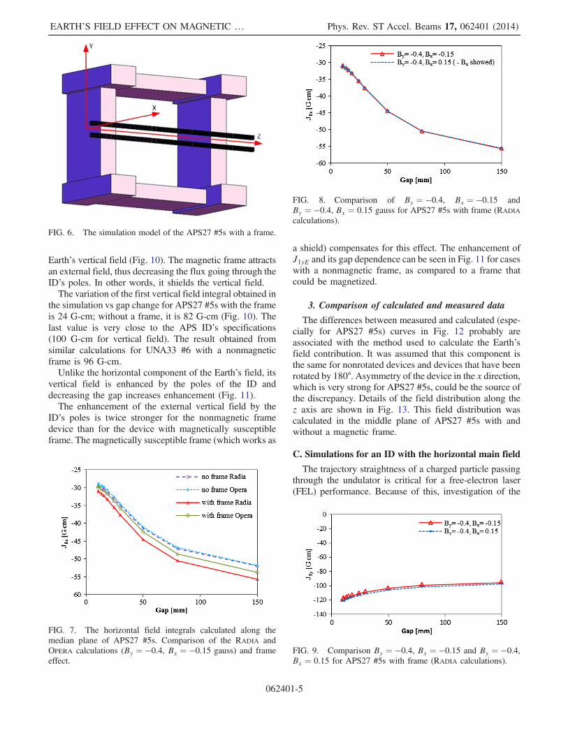
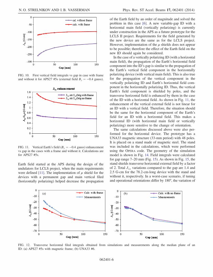
Earth’s vertical field (Fig. 10). The magnetic frame attractsan external field, thus decreasing the flux going through theID’s poles. In other words, it shields the vertical field.The variation of the first vertical field integral obtained in
the simulation vs gap change for APS27 #5s with the frameis 24 G-cm; without a frame, it is 82 G-cm (Fig. 10). Thelast value is very close to the APS ID’s specifications(100 G-cm for vertical field). The result obtained fromsimilar calculations for UNA33 #6 with a nonmagneticframe is 96 G-cm.Unlike the horizontal component of the Earth’s field, its
vertical field is enhanced by the poles of the ID anddecreasing the gap increases enhancement (Fig. 11).The enhancement of the external vertical field by the
ID’s poles is twice stronger for the nonmagnetic framedevice than for the device with magnetically susceptibleframe. The magnetically susceptible frame (which works as
a shield) compensates for this effect. The enhancement ofJ1yE and its gap dependence can be seen in Fig. 11 for caseswith a nonmagnetic frame, as compared to a frame thatcould be magnetized.
3. Comparison of calculated and measured data
The differences between measured and calculated (espe-cially for APS27 #5s) curves in Fig. 12 probably areassociated with the method used to calculate the Earth’sfield contribution. It was assumed that this component isthe same for nonrotated devices and devices that have beenrotated by 180°. Asymmetry of the device in the x direction,which is very strong for APS27 #5s, could be the source ofthe discrepancy. Details of the field distribution along thez axis are shown in Fig. 13. This field distribution wascalculated in the middle plane of APS27 #5s with andwithout a magnetic frame.
C. Simulations for an ID with the horizontal main field
The trajectory straightness of a charged particle passingthrough the undulator is critical for a free-electron laser(FEL) performance. Because of this, investigation of the
FIG. 6. The simulation model of the APS27 #5s with a frame.
FIG. 7. The horizontal field integrals calculated along themedian plane of APS27 #5s. Comparison of the RADIA andOPERA calculations (By ¼ −0.4, Bx ¼ −0.15 gauss) and frameeffect.
FIG. 8. Comparison of By ¼ −0.4, Bx ¼ −0.15 andBy ¼ −0.4, Bx ¼ 0.15 gauss for APS27 #5s with frame (RADIA
calculations).
FIG. 9. Comparison By ¼ −0.4, Bx ¼ −0.15 and By ¼ −0.4,Bx ¼ 0.15 for APS27 #5s with frame (RADIA calculations).
EARTH’S FIELD EFFECT ON MAGNETIC … Phys. Rev. ST Accel. Beams 17, 062401 (2014)
062401-5
Earth field started at the APS during the design of theundulators for LCLS project, when the main requirementswere defined [11]. The implementation of μ shield for thedevices with a permanent gap and main vertical filed(horizontally polarizing) helped decrease the propagation
of the Earth field by an order of magnitude and solved theproblem in this case [6]. A new variable-gap ID with ahorizontal main field (vertically polarizing) is currentlyunder construction in the APS as a future prototype for theLCLS II project. Requirements for the field generated bythe new device are the same as for the LCLS project.However, implementation of the μ shields does not appearto be possible; therefore the effect of the Earth field on thenew ID should again be considered.In the case of a vertically polarizing ID (with a horizontal
main field), the propagation of the Earth’s horizontal fieldcomponent into the ID’s gap is similar to the propagation ofthe Earth’s vertical field component in the horizontallypolarizing device (with vertical main field). This is also truefor the propagation of the vertical component in thevertically polarizing ID and Earth’s horizontal field com-ponent in the horizontally polarizing ID. Thus, the verticalEarth’s field component is shielded by poles, and thetransverse horizontal field is enhanced by them in the caseof the ID with a horizontal field. As shown in Fig. 11, theenhancement of the vertical external field is not linear foran ID with a vertical field. Therefore, the situation shouldbe the same for the horizontal component of the Earth’sfield for an ID with a horizontal field. This makes ahorizontal ID (with horizontal main field or verticallypolarizing) more sensitive to the change of orientation.The same calculations discussed above were also per-
formed for the horizontal device. The prototype has aUNA33 magnetic structure (33-mm period) with 48 poles.It is placed on a stand made of magnetic steel. The standwas included in the calculations, which were performedusing the OPERA code. The geometry of the simulationmodel is shown in Fig. 14. Field integrals were calculatedfor gap range 7–20 mm (Fig. 15). As shown in Fig. 15, thestand shields transverse horizontal external field by a factorof 2. Total J1x variations compared to the gap are 1.4 and2.5 G-cm for the 78.2-cm-long device with the stand andwithout it, respectively. In a worst-case scenario, if tuningand operational orientations differ by 180°, the variation of
FIG. 10. First vertical field integrals vs gap in case with frameand without it for APS27 #5s (external field By ¼ −0.4 gauss).
FIG. 11. Vertical Earth’s field (By ¼ −0.4 gauss) enhancementvs gap in the cases with a frame and without it. Calculations arefor APS27 #5s.
FIG. 12. Transverse horizontal filed integrals obtained from simulations and measurements along the median plane of anID: (a) APS27 #5s with magnetic frame; (b) UNA33 #6.
N. O. STRELNIKOV AND I. B. VASSERMAN Phys. Rev. ST Accel. Beams 17, 062401 (2014)
062401-6
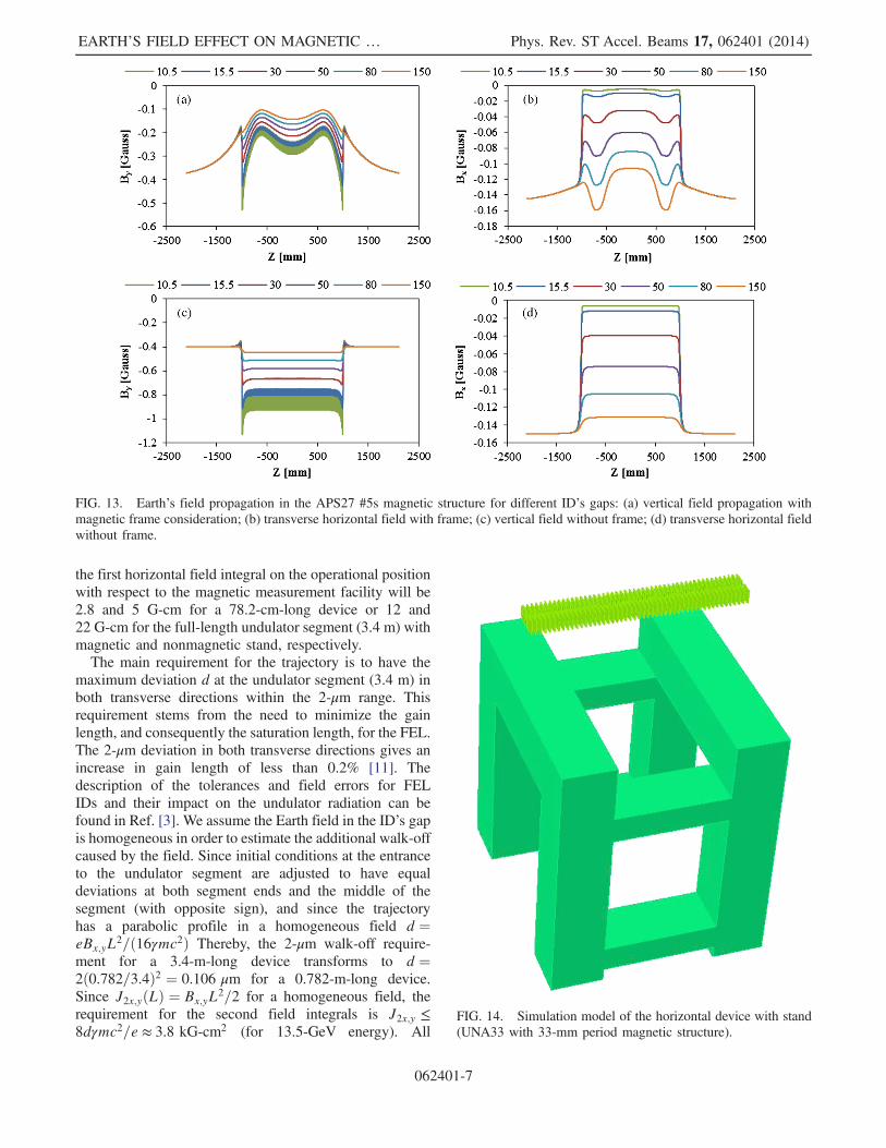
the first horizontal field integral on the operational positionwith respect to the magnetic measurement facility will be2.8 and 5 G-cm for a 78.2-cm-long device or 12 and22 G-cm for the full-length undulator segment (3.4 m) withmagnetic and nonmagnetic stand, respectively.The main requirement for the trajectory is to have the
maximum deviation d at the undulator segment (3.4 m) inboth transverse directions within the 2-μm range. Thisrequirement stems from the need to minimize the gainlength, and consequently the saturation length, for the FEL.The 2-μm deviation in both transverse directions gives anincrease in gain length of less than 0.2% [11]. Thedescription of the tolerances and field errors for FELIDs and their impact on the undulator radiation can befound in Ref. [3]. We assume the Earth field in the ID’s gapis homogeneous in order to estimate the additional walk-offcaused by the field. Since initial conditions at the entranceto the undulator segment are adjusted to have equaldeviations at both segment ends and the middle of thesegment (with opposite sign), and since the trajectoryhas a parabolic profile in a homogeneous field d ¼eBx;yL2=ð16γmc2Þ Thereby, the 2-μm walk-off require-ment for a 3.4-m-long device transforms to d ¼2ð0.782=3.4Þ2 ¼ 0.106 μm for a 0.782-m-long device.Since J2x;yðLÞ ¼ Bx;yL2=2 for a homogeneous field, therequirement for the second field integrals is J2x;y ≤8dγmc2=e ≈ 3.8 kG-cm2 (for 13.5-GeV energy). All
FIG. 13. Earth’s field propagation in the APS27 #5s magnetic structure for different ID’s gaps: (a) vertical field propagation withmagnetic frame consideration; (b) transverse horizontal field with frame; (c) vertical field without frame; (d) transverse horizontal fieldwithout frame.
FIG. 14. Simulation model of the horizontal device with stand(UNA33 with 33-mm period magnetic structure).
EARTH’S FIELD EFFECT ON MAGNETIC … Phys. Rev. ST Accel. Beams 17, 062401 (2014)
062401-7
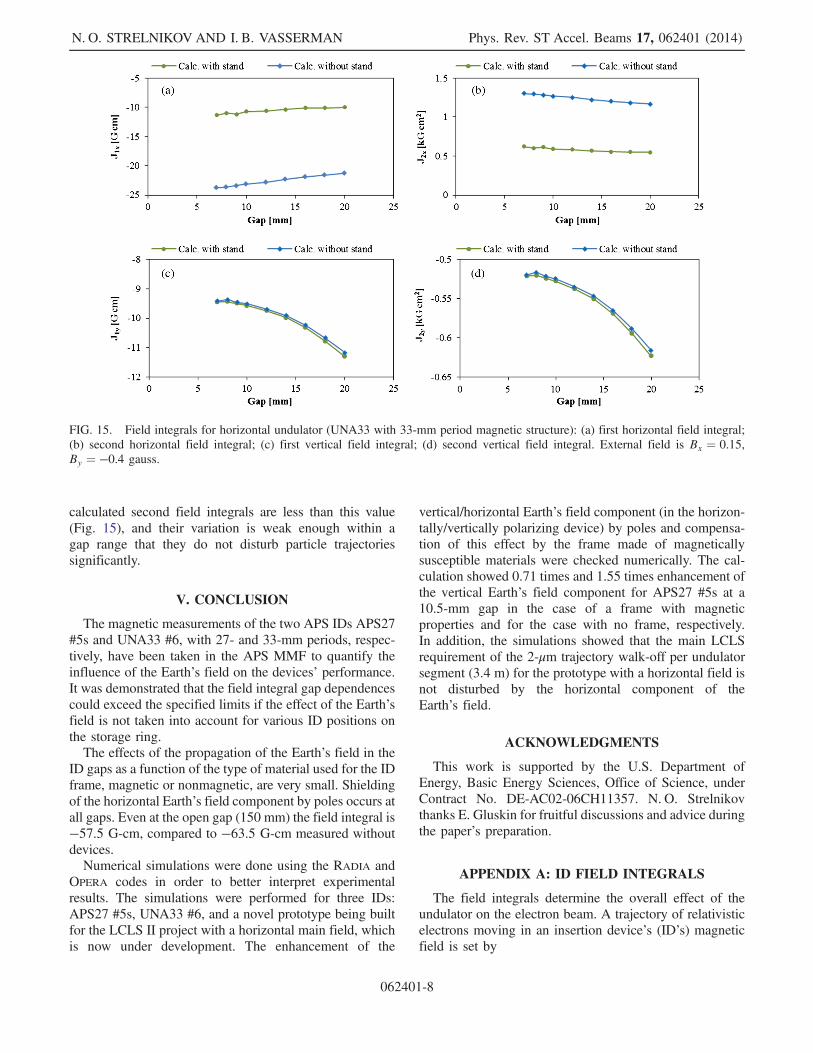
calculated second field integrals are less than this value(Fig. 15), and their variation is weak enough within agap range that they do not disturb particle trajectoriessignificantly.
V. CONCLUSION
The magnetic measurements of the two APS IDs APS27#5s and UNA33 #6, with 27- and 33-mm periods, respec-tively, have been taken in the APS MMF to quantify theinfluence of the Earth’s field on the devices’ performance.It was demonstrated that the field integral gap dependencescould exceed the specified limits if the effect of the Earth’sfield is not taken into account for various ID positions onthe storage ring.The effects of the propagation of the Earth’s field in the
ID gaps as a function of the type of material used for the IDframe, magnetic or nonmagnetic, are very small. Shieldingof the horizontal Earth’s field component by poles occurs atall gaps. Even at the open gap (150 mm) the field integral is−57.5 G-cm, compared to −63.5 G-cm measured withoutdevices.Numerical simulations were done using the RADIA and
OPERA codes in order to better interpret experimentalresults. The simulations were performed for three IDs:APS27 #5s, UNA33 #6, and a novel prototype being builtfor the LCLS II project with a horizontal main field, whichis now under development. The enhancement of the
vertical/horizontal Earth’s field component (in the horizon-tally/vertically polarizing device) by poles and compensa-tion of this effect by the frame made of magneticallysusceptible materials were checked numerically. The cal-culation showed 0.71 times and 1.55 times enhancement ofthe vertical Earth’s field component for APS27 #5s at a10.5-mm gap in the case of a frame with magneticproperties and for the case with no frame, respectively.In addition, the simulations showed that the main LCLSrequirement of the 2-μm trajectory walk-off per undulatorsegment (3.4 m) for the prototype with a horizontal field isnot disturbed by the horizontal component of theEarth’s field.
ACKNOWLEDGMENTS
This work is supported by the U.S. Department ofEnergy, Basic Energy Sciences, Office of Science, underContract No. DE-AC02-06CH11357. N. O. Strelnikovthanks E. Gluskin for fruitful discussions and advice duringthe paper’s preparation.
APPENDIX A: ID FIELD INTEGRALS
The field integrals determine the overall effect of theundulator on the electron beam. A trajectory of relativisticelectrons moving in an insertion device’s (ID’s) magneticfield is set by
FIG. 15. Field integrals for horizontal undulator (UNA33 with 33-mm period magnetic structure): (a) first horizontal field integral;(b) second horizontal field integral; (c) first vertical field integral; (d) second vertical field integral. External field is Bx ¼ 0.15,By ¼ −0.4 gauss.
N. O. STRELNIKOV AND I. B. VASSERMAN Phys. Rev. ST Accel. Beams 17, 062401 (2014)
062401-8
d2xdz2
≈ − eγmc2
By;d2ydz2
≈e
γmc2Bx:
Here x is the horizontal position of an electron transverse toelectron motion, y is the vertical position, and z is theposition along the longitudinal axis of an ID. Neglectingfocusing and the dependence of the undulator field ontransverse coordinates x and y, these equations have thefollowing solution:
x0 ¼ dxdz
≈ − eγmc2
J1yðzÞ þ x00;
y0 ¼ dydz
≈e
γmc2J1xðzÞ þ y00;
where J1yðzÞ ¼Rz0 Byð0; 0; z1Þdz1 is the first vertical field
integral, and J1xðzÞ ¼Rz0 Bxð0; 0; z1Þdz1 is the first hori-
zontal field integral. Integrating x0 and y0, one can get
x ≈ − eγmc2
J2yðzÞ þ x00zþ x0;
y ≈e
γmc2J2xðzÞ þ y00zþ y0;
where J2yðzÞ ¼Rz0
R z10 Byð0; 0; z2Þdz2dz1 is the
second vertical field integral, and J2xðzÞ ¼Rz0
R z10 Bxð0; 0; z2Þdz2dz1 is the second horizontal field
integral. Thus, the first field integrals of an ID definethe reference particle angle in the output of the device, andthe second field integrals define its offset [3].
APPENDIX B: EXTERNAL FIELDPROPAGATION IN AN ID’S GAP
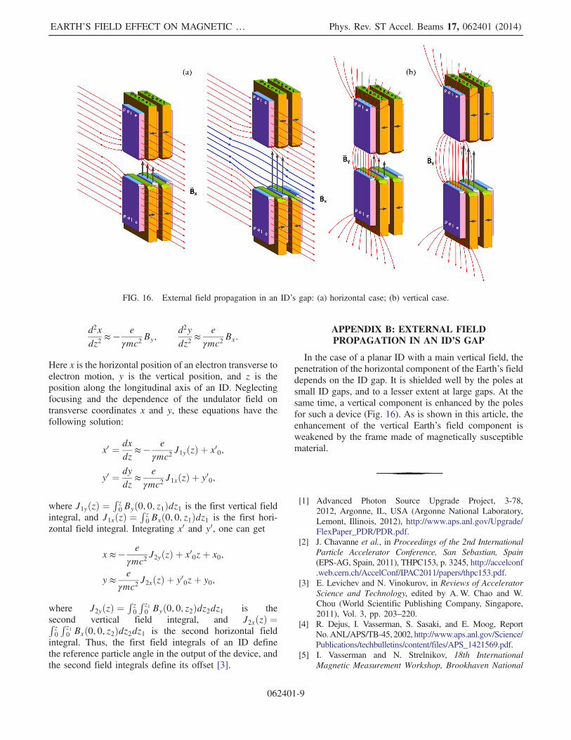
In the case of a planar ID with a main vertical field, thepenetration of the horizontal component of the Earth’s fielddepends on the ID gap. It is shielded well by the poles atsmall ID gaps, and to a lesser extent at large gaps. At thesame time, a vertical component is enhanced by the polesfor such a device (Fig. 16). As is shown in this article, theenhancement of the vertical Earth’s field component isweakened by the frame made of magnetically susceptiblematerial.
[1] Advanced Photon Source Upgrade Project, 3-78,2012, Argonne, IL, USA (Argonne National Laboratory,Lemont, Illinois, 2012), http://www.aps.anl.gov/Upgrade/FlexPaper_PDR/PDR.pdf.
[2] J. Chavanne et al., in Proceedings of the 2nd InternationalParticle Accelerator Conference, San Sebastian, Spain(EPS-AG, Spain, 2011), THPC153, p. 3245, http://accelconf.web.cern.ch/AccelConf/IPAC2011/papers/thpc153.pdf.
[3] E. Levichev and N. Vinokurov, in Reviews of AcceleratorScience and Technology, edited by A.W. Chao and W.Chou (World Scientific Publishing Company, Singapore,2011), Vol. 3, pp. 203–220.
[4] R. Dejus, I. Vasserman, S. Sasaki, and E. Moog, ReportNo.ANL/APS/TB-45, 2002, http://www.aps.anl.gov/Science/Publications/techbulletins/content/files/APS_1421569.pdf.
[5] I. Vasserman and N. Strelnikov, 18th InternationalMagnetic Measurement Workshop, Brookhaven National
FIG. 16. External field propagation in an ID’s gap: (a) horizontal case; (b) vertical case.
EARTH’S FIELD EFFECT ON MAGNETIC … Phys. Rev. ST Accel. Beams 17, 062401 (2014)
062401-9

Laboratory (Brookhaven National Laboratory, Upton,New York, 2013).
[6] S. Sasaki and I. Vasserman, in Proceedings of the 27thInternational Laser Conference, 2005, Stanford, CA, USA(SLAC National Accelerator Laboratory, Menlo Park,California, 2005).
[7] Yong-Chul Chae and G. Decker, in Proceedings of theParticle Accelerator Conference, Dallas, TX, 1995 (IEEE,New York, 1995), Vol. 5, pp. 3409–3411.
[8] P. Elleaume, O. Chubar, and J. Chavanne, in Proceedingsof the Particle Accelerator Conference, Vancouver,
BC, Canada, 1997 (IEEE, New York, 1997),pp. 3509–3511.
[9] RADIA 3D magnetostatics computer code, Technical Refer-ence Manual ESRF, Grenoble, France.
[10] OPERA 3D finite element code (TOSCA), CobhamTechnical Services, Oxfordshire, England.
[11] E. Gluskin, N. A. Vinokurov, G. Decker, R. J. Dejus, P.Emma, P. Ilinski, E. R. Moog, H.-D. Nuhn, and I. B.Vasserman, Nucl. Instrum. Methods Phys. Res. 475, 323(2001).
N. O. STRELNIKOV AND I. B. VASSERMAN Phys. Rev. ST Accel. Beams 17, 062401 (2014)
062401-10