Embed Size (px)
Citation preview
BRITISH STANDARD
BS 8002:1994Incorporating Amendments Nos. 1 and 2 and Corrigendum No. 1Code of practice for
Earth retaining structures
ICS 93.020
NO COPYING WITHOUT BSI PERMISSION EXCEPT AS PERMITTED BY COPYRIGHT LAW
BS 8002:1994
This British Standard, having been prepared under the direction of the Technical Sector Board for Building and Civil Engineering (B/-), was published under the authority of the Standards Board and comes into effect on15 April 1994
© BSI 12 September 2001
The following BSI references relate to the work on this standard:Committee reference B/526Draft for comment 87/14383 DC
ISBN 0 580 22826 6
A
A
8
1
1C
Committees responsible for this British Standard
The preparation of this British Standard was entrusted by the Technical Sector Board for Building and Civil Engineering (B/-) to Technical Committee B/526, upon which the following bodies were represented:
Association of Consulting Engineers
Association of Geotechnical Specialists
Department of the Environment (Construction Directorate)
Department of Transport
Federation of Civil Engineering Contractors
Federation of Piling Specialists
Institution of Civil Engineers
Institution of Structural Engineers
mendments issued since publication
md. No. Date Comments
851 November 1995
2062 May 2001 Indicated by a sideline in the margin
3386orr. No. 1
12 September 2001
Figures A.1 to A.8 replaced
BS 8002:1994
© BSI 12 September 2001
Contents
PageCommittees responsible Inside front coverForeword v
Section 1. Introduction1.1 Scope 11.2 References 11.3 Definitions 11.4 Major symbols 41.5 Selection and types of structure 51.5.1 General 51.5.2 Selection of type 5
Section 2. Data for design2.1 Site and geotechnical data 72.1.1 General 72.1.2 Site investigations 72.1.3 Ground water 72.1.4 Flood tides and waves 82.1.5 Climate 82.1.6 Trees 82.2 Soil properties 92.2.1 General 92.2.2 Selection and evaluation of soil parameter values 92.2.3 Clay soils 102.2.4 Cohesionless soils 132.2.5 Silts 132.2.6 Rock 132.2.7 Fill 152.2.8 Wall friction, base friction and undrained wall adhesion 162.3 Externally applied loads 17
Section 3. Design philosophy, design method and earth pressures3.1 Design philosophy 193.1.1 General 193.1.2 Limit state design 193.1.3 Ultimate limit states 193.1.4 Serviceability limit states 223.1.5 Limit states and compatibility of deformations 233.1.6 Design values of parameters 233.1.7 Applied loads 233.1.8 Design soil strength 233.1.9 Design earth pressures 243.2 Design method 243.2.1 Equilibrium calculations 243.2.2 Design situations 253.2.3 Calculations based on total and effective stress parameters 263.2.4 Design using total stress parameters 263.2.5 Design using effective stress parameters 273.2.6 Design values of wall friction, base friction and undrained
wall adhesion 27
i
BS 8002:1994
ii
Page3.2.7 Design to structural codes 283.3 Disturbing forces 283.3.1 General 283.3.2 At-rest earth pressures 283.3.3 Active earth pressures 293.3.4 Surcharge loads 333.3.5 Water pressure 353.4 Resistance to movement 393.4.1 General 393.4.2 Passive earth resistance 393.4.3 Weak rocks 413.4.4 Layered soils 413.4.5 Water pressures and seepage forces 41
Section 4. Design of specific earth retaining structures4.1 Interrelation of section 3 and section 4 434.1.1 General 434.1.2 Design 434.2 Gravity walls 434.2.1 General 434.2.2 Foundations 434.2.3 Mass concrete retaining walls 444.2.4 Unreinforced masonry retaining walls 494.2.5 Reinforced soil 514.2.6 Gabions 514.2.7 Cribwork 574.3 Reinforced concrete and reinforced masonry walls on
spread foundations 634.3.1 Reinforced concrete walls (other than basement walls) 634.3.2 Basement walls, excavation, support and retention systems 674.3.3 Reinforced and prestressed masonry retaining walls 724.4 Embedded walls 784.4.1 General 784.4.2 Types of wall and applicability 784.4.3 Design 784.4.4 Steel sheet piling 814.4.5 Timber sheet piles 854.4.6 Reinforced and prestressed concrete sheet piles 884.4.7 In situ concrete pile walls 884.4.8 Diaphragm walls 904.4.9 Soldier/king piles 924.5 Strutted excavations and cofferdams 954.5.1 General 954.5.2 Struts, ties, walings and anchorages 994.5.3 Cellular cofferdams 1014.6 Anchorages 1044.6.1 General 104
© BSI 12 September 2001
BS 8002:1994
© BSI 12 September 2001
Page4.6.2 Equilibrium 1044.6.3 Ground anchorages 1044.6.4 Tension piles 1054.6.5 Deadman anchorages 1054.7 Waterfront structures 1084.7.1 General 1084.7.2 Concrete and reinforcement 1084.7.3 Design 1084.7.4 Construction 112
Annex A (normative) Graphs for Ka and Kp 114Annex B (informative) Traditional design methods for embedded walls 122Annex C (informative) Bibliography 125
Index 129
Figure 1 — Strength envelopes for a given pre-consolidation 12Figure 2 — Derivation of N � from SPT value N 16Figure 3 — Limit states for earth retaining structures 20Figure 4 — Pressure diagrams 25Figure 5 — Graphical determination of active earth pressure forcohesionless soils 30Figure 6 — Graphical determination of active earth pressure forcohesive soils 33Figure 7 — Construction of earth pressure diagrams for earth retaining structures in multi-layered soil 35Figure 8 — Flow net determination of pore water pressure 36Figure 9 — Linear variation in hydraulic head 37Figure 10 — Graded filter drain 38Figure 11 — Foundations of gravity walls 45Figure 12 — Basic forms of mass concrete walls 46Figure 13 — Masonry clad mass concrete wall with cavity 48Figure 14 — Stepped and buttressed retaining walls inunreinforced masonry 50Figure 15 — Hexagonal woven mesh gabion cage (typical) 53Figure 16 — Welded mesh gabion cage (typical) 54Figure 17 — Examples of gabion retaining walls 57Figure 18 — Section and elevation of typical crib wall 58Figure 19 — Examples of timber cribwork 59Figure 20 — Examples of reinforced concrete cribwork 60Figure 21 — Further examples of reinforced concrete cribwork 61Figure 22 — Basic forms of reinforced concrete cantilever or stem wall 64Figure 23 — Basic forms of reinforced concrete counterfort andbuttressed walls 65Figure 24 — Temporary support against central dumping 68Figure 25 — Temporary support by fully braced trench 68Figure 26 — Long flying shores across excavations 69Figure 27 — Fully braced temporary support 69Figure 28 — Concurrent upward and downward construction 70Figure 29 — Floors cast on ground with excavation continuing below 71Figure 30 — Open cut 72Figure 31 — Reinforced masonry: grouted-cavity construction 73Figure 32 — Reinforced masonry: Quetta bond construction 74Figure 33 — Reinforced masonry: pocket-type construction 74
iii
BS 8002:1994
iv
PageFigure 34 — Reinforced hollow blockwork construction 75Figure 35 — Post-tensioned masonry diaphragm wall construction 76Figure 36 — Types of embedded retaining wall 79Figure 37 — Active pressure diagrams relating to maximum strut loads in braced earth retaining structures 80Figure 38 — Illustration of method of calculation of bending moments and frame loads by successive stage analysis in cofferdams 81Figure 39 — Typical sections of timber sheet piles 87Figure 40 — Detail of driving edge 87Figure 41 — Horizontal sheeting (lagging) 92Figure 42 — Vertical sheeting (lagging) 92Figure 43 — Composite steel soldier piles 93Figure 44 — Various methods of locating the sheeting (lagging) 94Figure 45 — Cofferdam for river crossing 96Figure 46 — Cofferdam in water 97Figure 47 — Types of cellular cofferdams 103Figure 48 — Types of anchorage 106Figure 49 — Non-interference of zones for anchored wall 107Figure 50 — Double wall construction where zones interfere 108Figure A.1 — Active pressure — Horizontal ground surface behind wall: Values of Ka (horizontal component) 114Figure A.2 — Passive pressure — Horizontal ground surface behind wall: Values of Kp (horizontal component) 115Figure A.3 — Active pressure — Sloping ground surface behind wall: Values of Ka (horizontal component) (based on Kerisel and Absi, 1990) 116Figure A.4 — Active pressure — Sloping ground surface behind wall: Values of Ka (horizontal component) (based on Kerisel and Absi, 1990) 117Figure A.5 — Active pressure — Sloping ground surface behind wall: Values of Ka (horizontal component) (based on Kerisel and Absi, 1990) 118Figure A.6 — Passive resistance — Sloping ground surface behind wall: Values of Kp (horizontal component) 119Figure A.7 — Passive resistance — Sloping ground surface behind wall: Values of Kp (horizontal component) 120Figure A.8 — Passive resistance — Sloping ground surface behind wall: Values of Kp (horizontal component) 121Figure B.1 — Different methods of assessing the ratio of restoring moments to overturning moments 123
Table 1 — Unit weights of soils (and similar materials) 9Table 2 — �� crit for clay soils 11Table 3 — �� for siliceous sands and gravels 14Table 4 — �� for rock 14Table 5 — Selection of pile size to suit driving conditions in granular soils using impact hammers 83Table 6 — Selection of pile size to suit driving conditions in cohesive soils 84
List of references 132
© BSI 12 September 2001
BS 8002:1994
© BSI 12 September 2001
Foreword
BS 8002 has been prepared under the direction of the Technical Sector Board for Building and Civil Engineering.
This code of practice is a complete revision of the Civil Engineering Code of Practice No. 2, which was issued by the Institution of Structural Engineers in 1951 on behalf of the Civil Engineering Codes of Practice Joint Committee.
A draft of this code of practice, was issued in 1988 for public comment and in 1992 a new committee reviewed and revised the text.
The main changes in the design of earth retaining structures in this code of practice are:
a) the recognition that effective stress analysis is the main basis for the assessment of earth pressures with total (undrained) stress analysis being important for some walls during or immediately following construction;
b) the need to take account of the effect of movement (or lack of it) upon the resulting earth pressures on the wall. The largest earth pressures which act on a retaining wall occur during working conditions. These earth pressures do not increase if the wall deforms sufficiently to approach failure conditions.
This code of practice takes into account that for small movements of a wall the shear strength developed in the soil is less than the maximum shear strength measured in a conventional triaxial test and furthermore that when large strains occur in the soil, the shear strength may reduce to the residual shear strength value.
It has been assumed in this code of practice that design of retaining walls is entrusted to chartered structural or chartered civil engineers who have sufficient knowledge of the principles and practice of soil mechanics as well as the principles and practice for the use of the appropriate structural materials, i.e. masonry, concrete, steel or timber.
This code of practice does not restrict designers from applying the results of research nor from taking advantage of special situations or previous experience in the design of retaining structures.
In this code of practice references have been made to non-BSI publications. The titles of these publications are given in Annex C.
The list of those engineers who have participated in the preparation of the initial draft, in the specially convened panel and in the more recently formed committee includes the majority of engineers who have a special interest in retaining walls. The Chairman throughout the long process of drafting, reviewing and complete redrafting, has been Mr. Thomas Akroyd, M.Sc. Tech, LL.B (Hons), C.Eng., a former President of the Institution of Structural Engineers.
BSI Committee B/526 whose constitution is shown in this British Standard, takes collective responsibility for its preparation under the authority of the Standards Board. The Committee wishes to acknowledge the personal contribution of:
Mr T N W Akroyd M.Sc. Tech, LL.B (Hons) (Chairman)
Dr M Bolton Ph.D., M.Sc., M.A. C.Eng., M.I.C.E.
Dr W G K Fleming B.Sc., Ph.D., C.Eng., M.I.C.E.
Dr B Simpson Ph.D., C.Eng., F.I.C.E.
Dr I F Symons Ph.D., C. Eng., F.I.C.E.1)
Mr K W Vickery B.Sc., F.G.S.
Mr D Waite C.Eng., M.I.C.E., F.I. Struct.E.1)
1) Deceased.
v
BS 8002:1994
vi
As a code of practice, this British Standard takes the form of guidance and recommendations. It should not be quoted as if it were a specification and particular care should be taken to ensure that claims of compliance are not misleading.
A British Standard dose not purport to include all the necessary provisions of a contract. Users of British Standards are responsible for their correct application.
Compliance with a British Standard does not of itself confer immunity from legal obligations.
Summary of pagesThis document comprises a front cover, an inside front cover, pages i to vi, pages 1 to 134, an inside back cover and a back cover.
The BSI copyright notice displayed in this document indicates when the document was last issued.
Sidelining in this document indicates the most recent changes by amendment.
© BSI 12 September 2001
BS 8002:1994
Section 1. Introduction 1
1.1 Scope
The subject of this code of practice is the design and construction of structures to retain soils and materials with similar engineering properties, at slopes steeper than those which they would naturally assume. The code of practice provides guidance for a designer, conversant with theoretical and applied soil mechanics and experienced in structural design and construction. The code is applicable to walls with a retained height of up to about 15 m. Many of its recommendations are of general applicable. Specialist advice should be sought with regard to the design and construction of larger structures and for those where movement of the retained soils requires close control.
The code is divided into four sections.
Section 1 explains the terms used in the document and summarizes the factors influencing the choice of a retaining wall.
Section 2 describes the site and geotechnical data that is required together with material properties. It gives guidance on the determination of the values of representative soil strength necessary for design purposes.
Section 3 identifies the design philosophy and the design methods for earth retaining structures, including the determination of earth pressures and the analysis of overall stable equilibrium. It defines design soil strength and considers the loads on retaining walls and the forces available to attain equilibrium with tolerable displacements. Guidance is given on methods of simple practical design and on the influence of ground conditions.
Section 4 considers in detail various individual types of structure and application of earth pressure theory together with matters of construction and maintenance.
1.2 References1.2.1 Normative references
This British Standard incorporates, by dated or undated reference, provisions from other publications. These normative references are made at the appropriate places in the text and the cited publications are listed on page 114. For dated references, only the edition cited applies; any subsequent amendments to or revisions of the cited publication apply to this British Standard only when incorporated in the reference by amendment or revision. For undated references, the latest edition of the cited publication applies, together with any amendments.
1.2.2 Informative references
This British Standard refers to other publications that provide information or guidance. Editions of these publications current at the time of issue of this standard are listed on the inside back cover, but reference should be made to the latest editions.
1.3 DefinitionsFor the purposes of this British Standard the following definitions apply and are limited to words used with special meaning in this document. Normal soil mechanics terminology is not defined.
1.3.1active earth pressurethe earth pressure exerted on the retaining wall by the retained soil. It may be greater than the fully active earth pressure (see 1.3.11 and 3.1.9)
1.3.2conservative valuesvalues of soil parameters which are more adverse than the most likely values. They may be less (or greater) than the most likely values. They tend towards the limit of the credible range of values
1.3.3design situationa set of physical conditions for which it should be demonstrated that a limit state (see 1.3.13 and 3.2.2) will not occur
© BSI 12 September 2001 1
BS 8002:1994 Section 1
1.3.4design soil strengthsoil strengths which are assumed will be mobilized at the occurrence of a limit state (see 1.3.13). The design value of soil strength is the lower of either the peak soil strength reduced by a mobilization factor (see 1.3.14) or the critical state strength
1.3.5design surcharge loadloading which is assumed to occur at some time during the life of the structure and for which the design should provide. See 3.2.2.2 and 3.3.4
1.3.6design value of a parameterthe value of the parameter entered into equilibrium calculations
1.3.7design value of wall frictionthe smaller of either the actual wall friction or adhesion measured by test or 75 % of design soil strength (see 1.3.4). See 2.2.8 and 3.2.6
1.3.8disturbing forcethe force exerted by retained soil on a retaining wall, tending to cause the wall to move. It includes the surcharge loads, external loads and water pressure. The minimum value is the fully active earth pressure (see 1.3.11)
1.3.9earth pressure coefficientsratio of horizontal effective stress to vertical effective stress. Ka is the fully active earth pressure (see 1.3.11) coefficient, Kp is the fully passive earth resistance (see 1.3.12) coefficient. Both are based on the design soil strength (see 1.3.4). Design values are determined from design values of soil parameters. Graphs are provided in Annex A for values of horizontal component of Ka and Kp. The values given in the various graphs in Annex A are for various ratios of �� and wall friction �
1.3.10embedded wallsformerly known as sheet pile walls, this term embraces walls of similar structural behaviour whether constructed of steel sheet piles, concrete piles, concrete diaphragms or timber. They are supported, at least in part, by passive earth resistance (see 1.3.15)
1.3.11fully active earth pressurethe minimum value of the active earth pressure (see 1.3.1), which occurs after sufficient movement or deflection of the retaining wall; the necessary movement is usually within the serviceability limit state (see 1.3.18) of the wall
1.3.12fully passive earth resistancethe maximum value of the passive earth resistance (see 1.3.15), which occurs after sufficient movement or deflection of the retaining wall. The necessary movement is often outside the serviceability limit state (see 1.3.18) of the wall
1.3.13limit stateany state of stability beyond which the retaining wall no longer satisfies the design performance requirements. A limit state is not associated with any particular method of structural design. See ultimate limit state (1.3.19) and serviceability limit state (1.3.18)
2 © BSI 12 September 2001
BS 8002:1994Section 1
1.3.14mobilization factora factor M of 1.2 or 1.5 (or more, see 3.2.4 and 3.2.5) applied to the representative soil shear strength to produce the design soil strength (see 1.3.4). M determines the proportion of the representative strength which may be mobilized at a limit state (see 1.3.13)
1.3.15passive earth resistancethe earth pressure generated by the soil when it resists movement of a retaining wall
1.3.16rapid shearingin the context of total stress analysis, the shearing of a soil at a rate sufficient to prevent or inhibit any significant pore water pressure dissipation so that cu is the operative shear strength
1.3.17representative soil strengthConservative estimate of the mass strength of the soil. The value is determined from reliable site investigation and soil test data. In the absence of such data, see Table 1, Table 2, Table 3 and Table 4
1.3.18serviceability limit statestate of deformation of a retaining wall such that its use is affected, its durability is impaired, its maintenance requirements are substantially increased or damage is caused to non-structural elements. Alternatively such movement of the earth retaining structure which may affect adjacent structures or services in a like manner
1.3.19ultimate limit statestate of collapse, instability or forms of failure that may endanger property or people or cause major economic loss
1.3.20unplanned excavationthe minimum depth, below the nominal finished surface in front of the wall, which it is assumed, for design purposes, will be excavated at some time during the life of the retaining wall. See 3.2.2.2
© BSI 12 September 2001 3
BS 8002:1994 Section 1
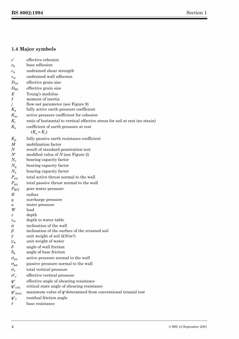
1.4 Major symbols
c� effective cohesioncb base adhesioncu undrained shear strengthcw undrained wall adhesionD10 effective grain sizeD60 effective grain sizeE Young’s modulusI moment of inertiaj flow-net parameter (see Figure 9)Ka fully active earth pressure coefficientKac active pressure coefficient for cohesionKi ratio of horizontal to vertical effective stress for soil at rest (no strain)Ko coefficient of earth pressure at rest
Kp fully passive earth resistance coefficientM mobilization factorN result of standard penetration testN� modified value of N (see Figure 2)Nc bearing capacity factorNq bearing capacity factorNy bearing capacity factorPan total active thrust normal to the wallPpn total passive thrust normal to the wallPWT pore water pressureR radiusq surcharge pressureu water pressureW loadz depthzw depth to water table� inclination of the wall� inclination of the surface of the retained soil� unit weight of soil (kN/m3)�w unit weight of water� angle of wall friction�b angle of base friction�an active pressure normal to the wall�pn passive pressure normal to the wall�v total vertical pressure��v effective vertical pressure�� effective angle of shearing resistance��crit critical state angle of shearing resistance��max maximum value of ���determined from conventional triaxial test��r residual friction angle� base resistance
Ko Ki�� �
4 © BSI 12 September 2001
BS 8002:1994Section 1
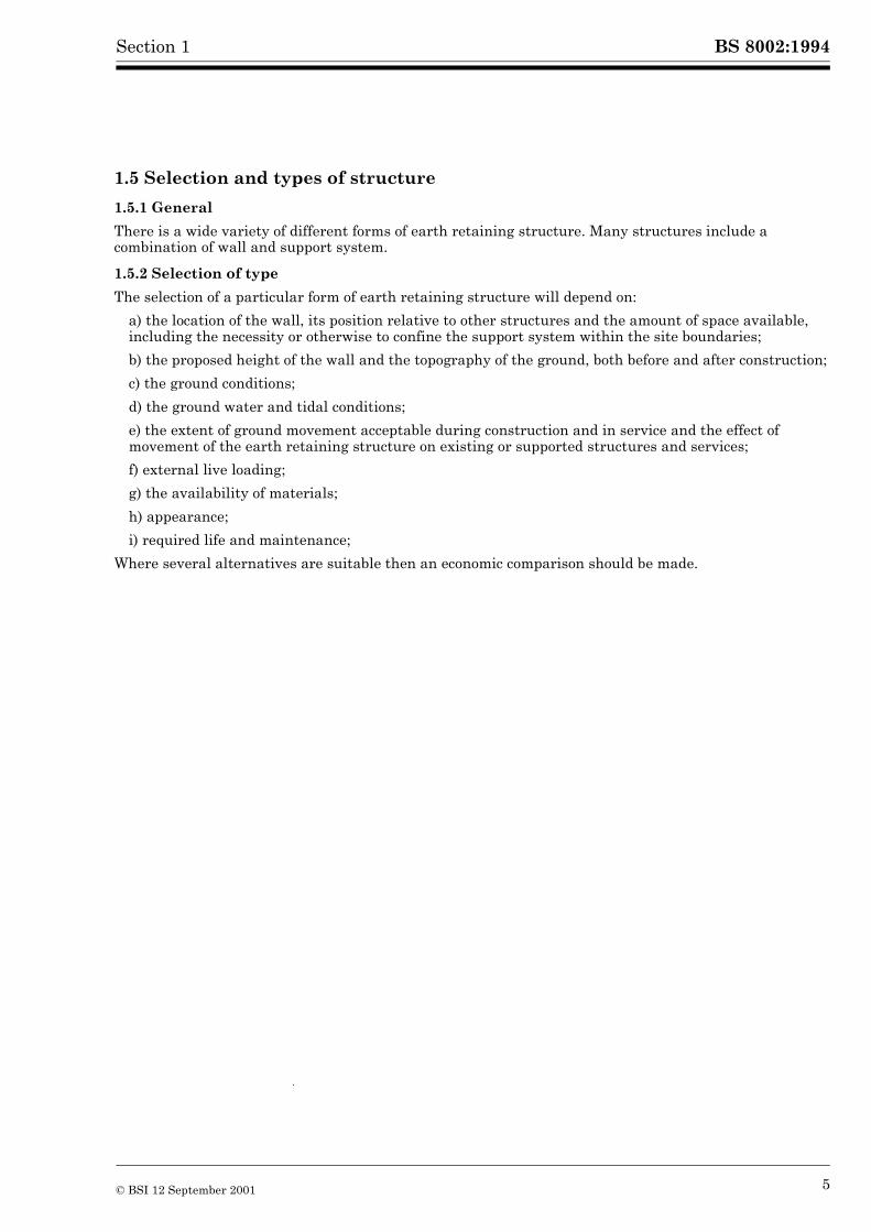
1.5 Selection and types of structure
1.5.1 General
There is a wide variety of different forms of earth retaining structure. Many structures include a combination of wall and support system.
1.5.2 Selection of type
The selection of a particular form of earth retaining structure will depend on:
a) the location of the wall, its position relative to other structures and the amount of space available, including the necessity or otherwise to confine the support system within the site boundaries;
b) the proposed height of the wall and the topography of the ground, both before and after construction;
c) the ground conditions;
d) the ground water and tidal conditions;
e) the extent of ground movement acceptable during construction and in service and the effect of movement of the earth retaining structure on existing or supported structures and services;
f) external live loading;
g) the availability of materials;
h) appearance;
i) required life and maintenance;
Where several alternatives are suitable then an economic comparison should be made.
© BSI 12 September 2001 5

6 blank
BS 8002:1994
Section 2. Data for design 2
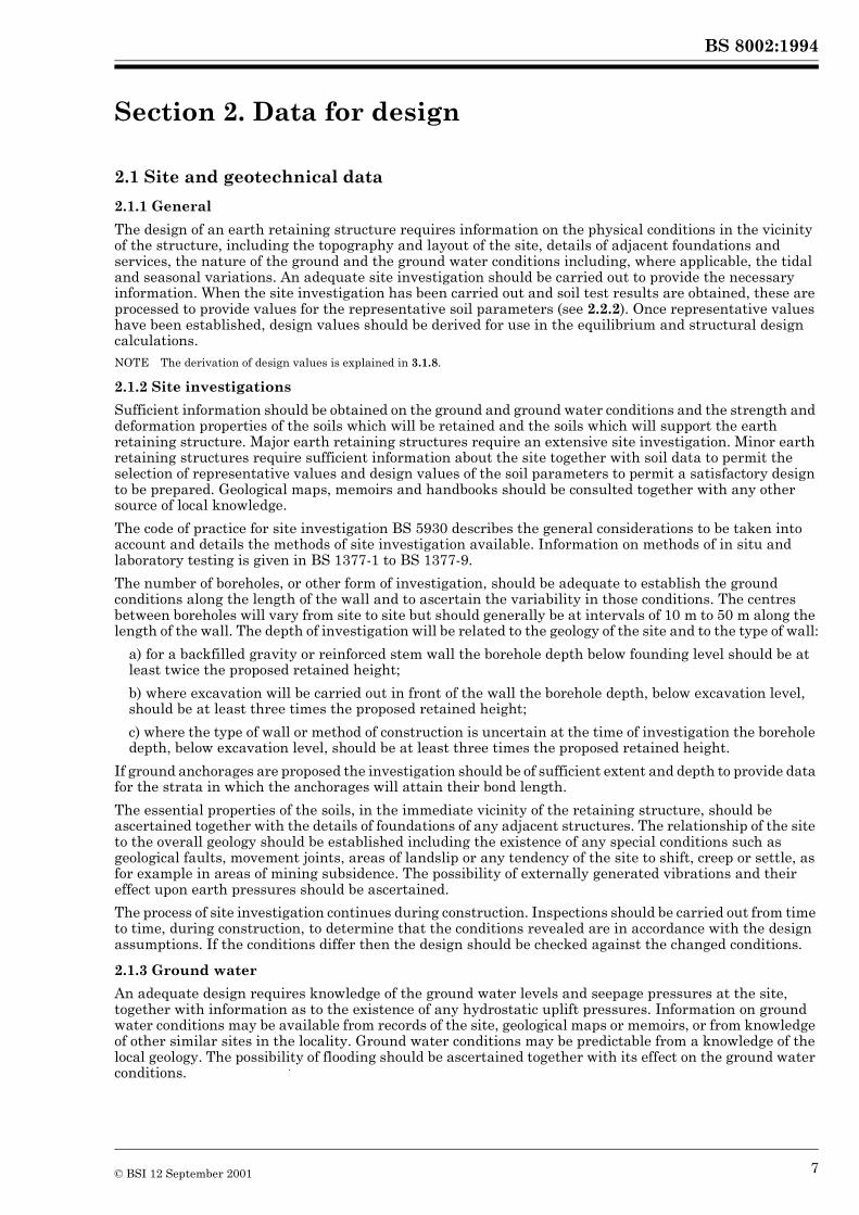
2.1 Site and geotechnical data
2.1.1 General
The design of an earth retaining structure requires information on the physical conditions in the vicinity of the structure, including the topography and layout of the site, details of adjacent foundations and services, the nature of the ground and the ground water conditions including, where applicable, the tidal and seasonal variations. An adequate site investigation should be carried out to provide the necessary information. When the site investigation has been carried out and soil test results are obtained, these are processed to provide values for the representative soil parameters (see 2.2.2). Once representative values have been established, design values should be derived for use in the equilibrium and structural design calculations.NOTE The derivation of design values is explained in 3.1.8.
2.1.2 Site investigations
Sufficient information should be obtained on the ground and ground water conditions and the strength and deformation properties of the soils which will be retained and the soils which will support the earth retaining structure. Major earth retaining structures require an extensive site investigation. Minor earth retaining structures require sufficient information about the site together with soil data to permit the selection of representative values and design values of the soil parameters to permit a satisfactory design to be prepared. Geological maps, memoirs and handbooks should be consulted together with any other source of local knowledge.
The code of practice for site investigation BS 5930 describes the general considerations to be taken into account and details the methods of site investigation available. Information on methods of in situ and laboratory testing is given in BS 1377-1 to BS 1377-9.
The number of boreholes, or other form of investigation, should be adequate to establish the ground conditions along the length of the wall and to ascertain the variability in those conditions. The centres between boreholes will vary from site to site but should generally be at intervals of 10 m to 50 m along the length of the wall. The depth of investigation will be related to the geology of the site and to the type of wall:
a) for a backfilled gravity or reinforced stem wall the borehole depth below founding level should be at least twice the proposed retained height;
b) where excavation will be carried out in front of the wall the borehole depth, below excavation level, should be at least three times the proposed retained height;
c) where the type of wall or method of construction is uncertain at the time of investigation the borehole depth, below excavation level, should be at least three times the proposed retained height.
If ground anchorages are proposed the investigation should be of sufficient extent and depth to provide data for the strata in which the anchorages will attain their bond length.
The essential properties of the soils, in the immediate vicinity of the retaining structure, should be ascertained together with the details of foundations of any adjacent structures. The relationship of the site to the overall geology should be established including the existence of any special conditions such as geological faults, movement joints, areas of landslip or any tendency of the site to shift, creep or settle, as for example in areas of mining subsidence. The possibility of externally generated vibrations and their effect upon earth pressures should be ascertained.
The process of site investigation continues during construction. Inspections should be carried out from time to time, during construction, to determine that the conditions revealed are in accordance with the design assumptions. If the conditions differ then the design should be checked against the changed conditions.
2.1.3 Ground water
An adequate design requires knowledge of the ground water levels and seepage pressures at the site, together with information as to the existence of any hydrostatic uplift pressures. Information on ground water conditions may be available from records of the site, geological maps or memoirs, or from knowledge of other similar sites in the locality. Ground water conditions may be predictable from a knowledge of the local geology. The possibility of flooding should be ascertained together with its effect on the ground water conditions.
© BSI 12 September 2001 7
BS 8002:1994 Section 2
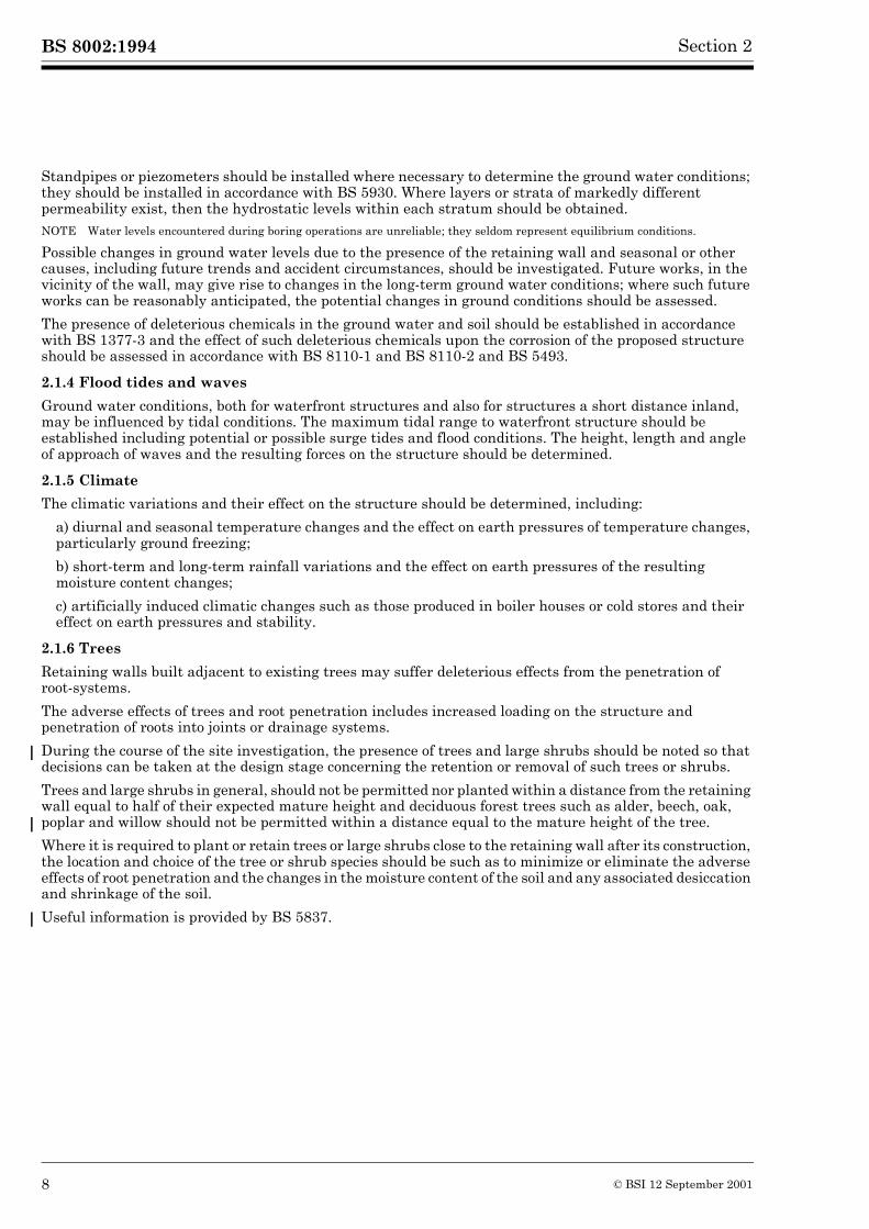
Standpipes or piezometers should be installed where necessary to determine the ground water conditions; they should be installed in accordance with BS 5930. Where layers or strata of markedly different permeability exist, then the hydrostatic levels within each stratum should be obtained.NOTE Water levels encountered during boring operations are unreliable; they seldom represent equilibrium conditions.
Possible changes in ground water levels due to the presence of the retaining wall and seasonal or other causes, including future trends and accident circumstances, should be investigated. Future works, in the vicinity of the wall, may give rise to changes in the long-term ground water conditions; where such future works can be reasonably anticipated, the potential changes in ground conditions should be assessed.
The presence of deleterious chemicals in the ground water and soil should be established in accordance with BS 1377-3 and the effect of such deleterious chemicals upon the corrosion of the proposed structure should be assessed in accordance with BS 8110-1 and BS 8110-2 and BS 5493.
2.1.4 Flood tides and waves
Ground water conditions, both for waterfront structures and also for structures a short distance inland, may be influenced by tidal conditions. The maximum tidal range to waterfront structure should be established including potential or possible surge tides and flood conditions. The height, length and angle of approach of waves and the resulting forces on the structure should be determined.
2.1.5 Climate
The climatic variations and their effect on the structure should be determined, including:
a) diurnal and seasonal temperature changes and the effect on earth pressures of temperature changes, particularly ground freezing;
b) short-term and long-term rainfall variations and the effect on earth pressures of the resulting moisture content changes;
c) artificially induced climatic changes such as those produced in boiler houses or cold stores and their effect on earth pressures and stability.
2.1.6 Trees
Retaining walls built adjacent to existing trees may suffer deleterious effects from the penetration of root-systems.
The adverse effects of trees and root penetration includes increased loading on the structure and penetration of roots into joints or drainage systems.
During the course of the site investigation, the presence of trees and large shrubs should be noted so that decisions can be taken at the design stage concerning the retention or removal of such trees or shrubs.
Trees and large shrubs in general, should not be permitted nor planted within a distance from the retaining wall equal to half of their expected mature height and deciduous forest trees such as alder, beech, oak, poplar and willow should not be permitted within a distance equal to the mature height of the tree.
Where it is required to plant or retain trees or large shrubs close to the retaining wall after its construction, the location and choice of the tree or shrub species should be such as to minimize or eliminate the adverse effects of root penetration and the changes in the moisture content of the soil and any associated desiccation and shrinkage of the soil.
Useful information is provided by BS 5837.
8 © BSI 12 September 2001
BS 8002:1994Section 2
2.2 Soil properties
2.2.1 General
The design of earth retaining structures usually involves an effective stress analysis, although in some circumstances a total stress design may be appropriate, accordingly data on the soil properties in respect of both strength (see 1.3.17) and stiffness under both drained and undrained conditions should be obtained. Soil properties are determined as part of the site investigation process but may be amplified by data from back analysis of comparable retaining structures in similar ground conditions.
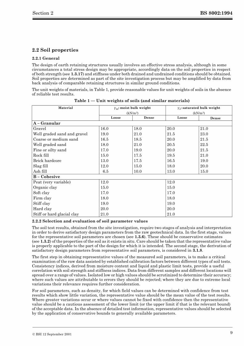
The unit weights of materials, in Table 1, provide reasonable values for unit weights of soils in the absence of reliable test results.
Table 1 — Unit weights of soils (and similar materials)
2.2.2 Selection and evaluation of soil parameter values
The soil test results, obtained from the site investigation, require two stages of analysis and interpretation in order to derive satisfactory design parameters from the raw geotechnical data. In the first stage, values for the representative soil parameters are chosen (see 1.3.6). These should be conservative estimates (see 1.3.2) of the properties of the soil as it exists in situ. Care should be taken that the representative value is properly applicable to the part of the design for which it is intended. The second stage, the derivation of satisfactory design parameters from representative soil parameters, is considered in 3.1.8.
The first step in obtaining representative values of the measured soil parameters, is to make a critical examination of the raw data assisted by established calibration factors between different types of soil tests. Consistency indices, derived from moisture content and liquid and plastic limit tests, provide a useful correlation with soil strength and stiffness indices. Data from different samples and different locations will spread over a range of values. Isolated low or high values should be scrutinized to determine their accuracy; where such values are attributable to errors they should be rejected; where they are due to extreme local variations their relevance requires further consideration.
For soil parameters, such as density, for which field values can be determined with confidence from test results which show little variation, the representative value should be the mean value of the test results. Where greater variations occur or where values cannot be fixed with confidence then the representative value should be a cautious assessment of the lower limit (or the upper limit if that is the relevant bound) of the acceptable data. In the absence of detailed test information, representative values should be selected by the application of conservative bounds to generally available parameters.
Material �m: moist bulk weight
(kN/m3)
�s: saturated bulk weight
(kN/m3)Loose Dense Loose Dense
A – GranularGravel 16.0 18.0 20.0 21.0Well graded sand and gravel 19.0 21.0 21.5 23.0Coarse or medium sand 16.5 18.5 20.0 21.5Well graded sand 18.0 21.0 20.5 22.5Fine or silty sand 17.0 19.0 20.0 21.5Rock fill 15.0 17.5 19.5 21.0Brick hardcore 13.0 17.5 16.5 19.0Slag fill 12.0 15.0 18.0 20.0Ash fill 6.5 10.0 13.0 15.0B – CohesivePeat (very variable) 12.0 12.0Organic clay 15.0 15.0Soft clay 17.0 17.0Firm clay 18.0 18.0Stiff clay 19.0 19.0Hard clay 20.0 20.0Stiff or hard glacial clay 21.0 21.0
© BSI 12 September 2001 9
BS 8002:1994 Section 2
The selection of representative values of soil parameters should take the following matters into account:
a) geological and other background information;
b) differences between the in situ conditions and the properties measured by field or laboratory tests;
c) the effect of construction activities on the properties of the ground;
d) changes which may occur in the field due to variations in the environment or weather;
e) relevant data from previous projects and the performance of existing facilities.
Careful assessment of the soil parameter values is necessary to ensure selection of those values which are pertinent to the behaviour of retaining structures. The assessment of the proper parameter value is often dependent on the mechanism or mode of deformation being considered for the retaining structure, for example, different representative strengths will be required for a shear failure in a fissured material depending upon whether the shear surface is free to follow the fissures or is constrained to intersect intact material. A range of values should be considered particularly, if the soil parameter values are likely to change during the lifetime of the retaining structure.
Under serviceability conditions, where deformations are comparatively small, the soil will operate at below peak strength conditions. The appropriate strength and stiffness values may be obtained by examining the stress-strain behaviour of the soil, as given for example by laboratory triaxial tests. Under ultimate limit state conditions where deformations are comparatively large, the soil will operate at beyond peak strength conditions and may dilate to approach the critical state values consistent with the strength envelope for loose or normally consolidated soils.
Table 2, Table 3 and Table 4 provide guidance on the empirical relationship between classification and index tests and representative values of the angle of shearing resistance and the density of various materials.
2.2.3 Clay soils
The construction of a retaining wall may result in changes in the strength of the ground in the vicinity of the wall. Where the mass permeability of the ground is low the changes of strength take place over some time and therefore it is necessary to determine parameter values applicable to both short-term and to long-term conditions, i.e. undrained and drained conditions.
The undrained shear strength of a clay soil is not a fundamental soil property. Different values may be recorded in triaxial compression and extension, in direct shear and in pressuremeter tests in situ. Although conventional practice has been based on triaxial compression tests, which are consistent with active soil conditions, extension tests may be required if the behaviour of a passive zone is of particular concern.
The undrained strength of a soft clay with a small overconsolidated ratio (less than 3) increases when the positive pore pressures dissipate; but the negative pore pressures induced by shearing a stiff clay, with a high overconsolidation ratio, cause it to swell and soften in the long-term. If the undrained strength of a stiff clay is to be relied upon during temporary works construction then care is necessary to ensure that there are no sand or silt partings containing free ground water which would affect the undrained shear strength; such permeable zones are common in clays.
In assessing the strength of clay soils, particularly from undrained tests in accordance with BS 1377-7, the procedures used for sampling and testing should be taken into account. For example, U100 sampling of stiff clays leads to partial remoulding and the creation of excess negative pore pressures; these in turn cause excessive initial effective stresses which can lead to unconsolidated tests registering erroneously high undrained strengths, even when the water content has been preserved. This is due to the mode of failure of heavily overconsolidated clays, which, by strain softening, lead to shear rupture. Such failures occur at strengths lower than those applicable at the same water content but lower overconsolidation ratio. More consistent results are obtained if samples are consolidated to a best estimate of in situ effective stresses prior to shearing. Representative values for undrained strength parameters should be assessed for the peak strength and for the remoulded strength of the soil. The values for the representative peak strength should make due allowance for the influence of sampling and the method of testing, as well as for likely softening on excavation.
10 © BSI 12 September 2001
BS 8002:1994Section 2
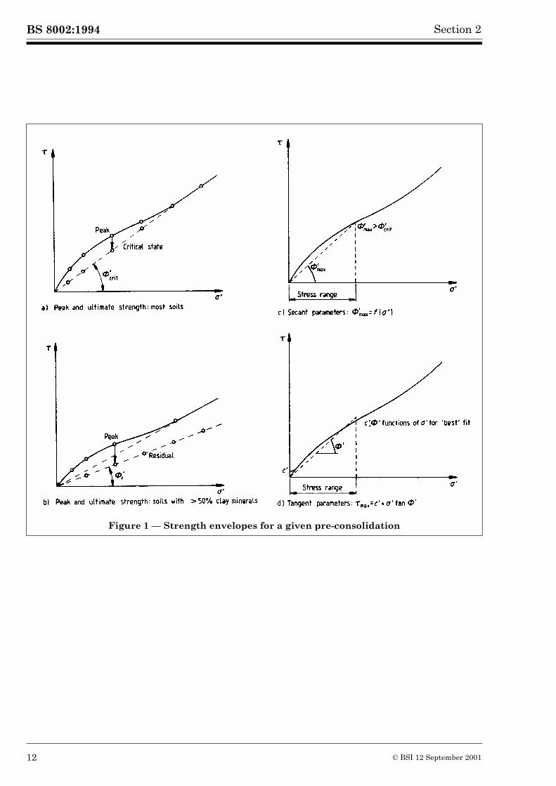
To determine the strength of clay soils, for an effective stress analysis, triaxial tests may be carried out either fully drained or undrained with pore pressure measurement, provided the samples are fully saturated in accordance with BS 1377-7 and BS 1377-8. The tests are carried out sufficiently slowly to ensure equalization of pore pressures. The Mohr-Coulomb failure envelope for overconsolidated clays, of initially identical samples, is generally curved, see Figure 1. At effective pressures close to the preconsolidation pressure, the soil mobilizes its critical state angle of shearing ��crit. At lower initial effective stresses, i.e. at higher overconsolidated ratios, the soil exhibits a dilatant peak at failure before its strength drops to, and possibly beyond, the critical state value. Representative values should be assessed separately for the peak strength and for the critical state strength of the soil. The representative peak strength should be appropriate to the anticipated stress state of the soil in the ground. Where the stress-strain curve never reaches a peak, during the maximum strain range achievable during test, the peak strength should be assumed to be the largest strength mobilized during the test. It may be represented by values of c� and �� or by secant values of ��� The representative critical state strength is represented by the critical state angle of shearing resistance, ��crit. Cohesive soils with high clay contents exhibit the greatest fall from peak to residual strength, forming a polished rupture surface. Previous shear surfaces, in plastic clays, may be reactivated at low residual friction angles ��r. First time slides due to new construction have been found to mobilize mass strengths no lower than ��crit.
Two approaches may be adopted for the conventional linearization of the peak soil envelope over some desired range of stress, see Figure 1. A secant �� value can be selected as a function of stress level. If a single value is chosen, the resulting envelope is linear to the origin and falls safely inside the envelope of tests carried out from identical initial conditions. Since soil samples from the field are not identical, the method should normally be applied by selecting the lowest secant �� for any sample tested within the target range of stress. Alternatively, the tangent parameters (c�, ��) may be used, where each is a function of stress level for identical samples. Sample variation causes scatter in the tangent parameter values and conservative values are best selected by fitting a lower bound to the relevant data, taking care to consider the range of effective stress required.
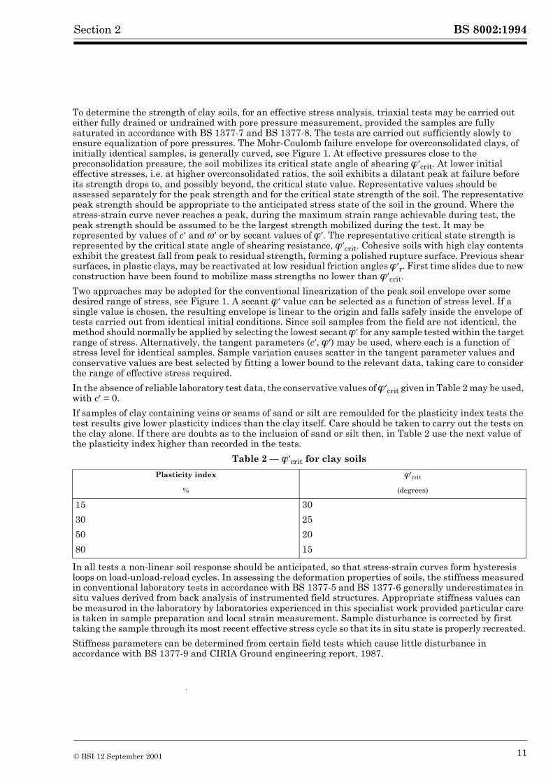
In the absence of reliable laboratory test data, the conservative values of ��crit given in Table 2 may be used, with c� = 0.
If samples of clay containing veins or seams of sand or silt are remoulded for the plasticity index tests the test results give lower plasticity indices than the clay itself. Care should be taken to carry out the tests on the clay alone. If there are doubts as to the inclusion of sand or silt then, in Table 2 use the next value of the plasticity index higher than recorded in the tests.
Table 2 — ��crit for clay soils
In all tests a non-linear soil response should be anticipated, so that stress-strain curves form hysteresis loops on load-unload-reload cycles. In assessing the deformation properties of soils, the stiffness measured in conventional laboratory tests in accordance with BS 1377-5 and BS 1377-6 generally underestimates in situ values derived from back analysis of instrumented field structures. Appropriate stiffness values can be measured in the laboratory by laboratories experienced in this specialist work provided particular care is taken in sample preparation and local strain measurement. Sample disturbance is corrected by first taking the sample through its most recent effective stress cycle so that its in situ state is properly recreated.
Stiffness parameters can be determined from certain field tests which cause little disturbance in accordance with BS 1377-9 and CIRIA Ground engineering report, 1987.
Plasticity index ��crit
% (degrees)
15 30
30 25
50 20
80 15
© BSI 12 September 2001 11
BS 8002:1994 Section 2
Figure 1 — Strength envelopes for a given pre-consolidation
12 © BSI 12 September 2001
BS 8002:1994Section 2
2.2.4 Cohesionless soils
The strength and stiffness of cohesionless soils are determined indirectly by in situ static or dynamic penetration tests. Details of three types of penetration tests as well as plate loading tests are given in BS 1377-9. The peak and critical state angles of shearing resistance for siliceous sands and gravels may be estimated from the following equations:
The estimated peak effective angle of shearing resistance is given by:
The estimated critical state angle of shearing resistance is given by:
��crit = 30 + A + B
The values of:
A = angularity of the particlesB = grading of the sand/gravelC = results of standard penetration tests
are given in Table 3.
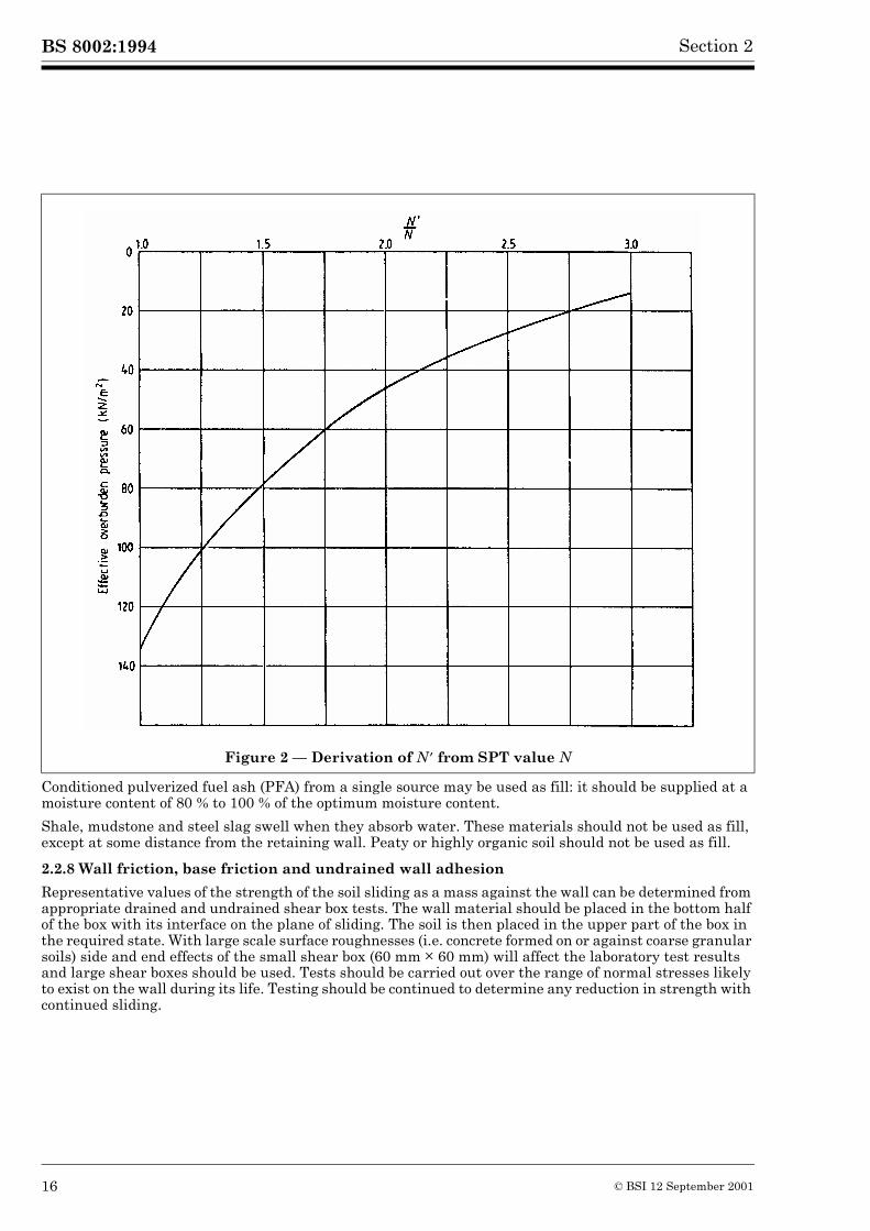
The standard penetration test (SPT) values should be corrected for the effect of overburden pressure in accordance with Figure 2 (see Thorburn, 1963); other correction effects may be necessary. See CIRIA Report FR/CP/72). Bolton (1986) has introduced empirical relations between ��max�, ��crit� initial soil relative density and mean effective stress at failure to reflect the change in the secant value of peak angle of shearing resistance with the change in the mean effective stress in the ground.
2.2.5 Silts
It is difficult and often impracticable to obtain undisturbed samples of silts and fine sands, even employing special sampling techniques. Loose silts are readily liquified by vibration, both during probing and during the life of the retaining wall; accordingly excess pore pressures should be taken into account. Inorganic siliceous silts can generate as much dilatancy as sands, at the same relative density, but they more easily soften to critical states in thin rupture bands. In the absence of other data and where disturbed samples have shown the silt is a rock flour with negligible organic or clay mineral content, the representative effective angle of shearing may be conservatively taken as ��crit in Table 3.
2.2.6 Rock
The engineering properties of rock relevant in design are controlled by the extent and orientation of the bedding planes and joints within the rock mass together with the water pressures on the discontinuity planes. The site investigation should establish the strength and orientation of the discontinuity planes. Weak rocks, particularly weakly cemented sandstones, fissured shales and chalk, are often difficult materials to sample and test.
Some correlation has been obtained between the standard penetration test in accordance with BS 1377-9 and the strength and stiffness properties for certain weak rock masses. In addition the mass rock properties may be derived from compression wave and shear wave velocity measurements.
The following indicative values of the effective angle of friction in Table 4 relate to rocks which can conservatively be treated as composed of granular fragments, i.e. they are closely and randomly jointed or otherwise fractured, having an RQD (rock quality designation) value close to zero.
��max = 30 + A + B + C (1)
2) In preparation.
© BSI 12 September 2001 13
BS 8002:1994 Section 2
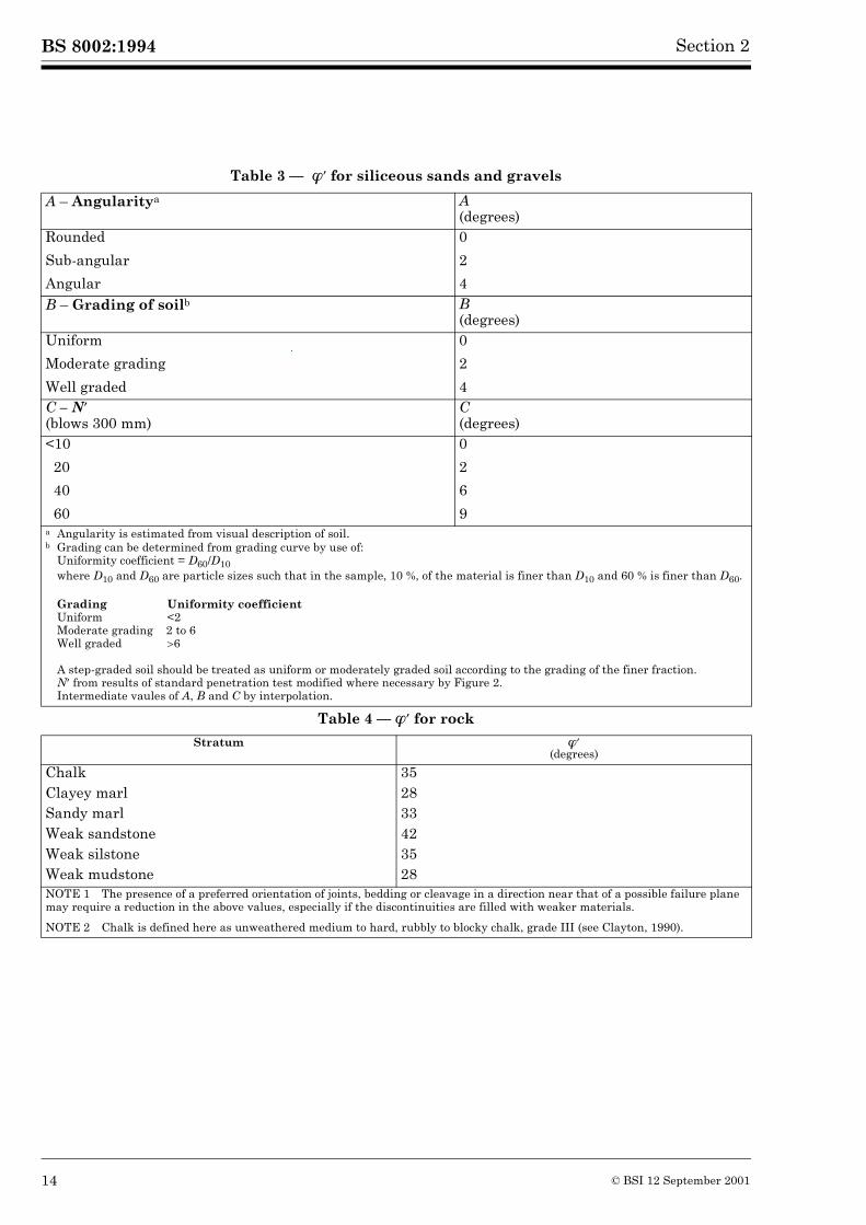
Table 3 — ��������� �for siliceous sands and gravels
Table 4 — ���� for rock
A – Angularitya A(degrees)
Rounded
Sub-angular
Angular
0
2
4B – Grading of soilb B
(degrees)Uniform
Moderate grading
Well graded
0
2
4C – N�
(blows 300 mm)C(degrees)
<10
20
40
60
0
2
6
9a Angularity is estimated from visual description of soil.b Grading can be determined from grading curve by use of:
Uniformity coefficient = D60/D10 where D10 and D60 are particle sizes such that in the sample, 10 %, of the material is finer than D10 and 60 % is finer than D60.
Grading Uniformity coefficient Uniform <2Moderate grading 2 to 6Well graded �6
A step-graded soil should be treated as uniform or moderately graded soil according to the grading of the finer fraction.N� from results of standard penetration test modified where necessary by Figure 2.Intermediate vaules of A, B and C by interpolation.
Stratum ��
(degrees)
Chalk 35Clayey marl 28Sandy marl 33Weak sandstone 42Weak silstone 35Weak mudstone 28NOTE 1 The presence of a preferred orientation of joints, bedding or cleavage in a direction near that of a possible failure plane may require a reduction in the above values, especially if the discontinuities are filled with weaker materials.
NOTE 2 Chalk is defined here as unweathered medium to hard, rubbly to blocky chalk, grade III (see Clayton, 1990).
14 © BSI 12 September 2001
BS 8002:1994Section 2
2.2.7 Fill
A wide range of materials may be used as fill behind retaining walls. Selected cohesionless granular fill placed in a controlled manner such as well graded small rockfills, gravels and sands, are suitable as fill. Cohesive materials, subject to the further recommendations below, may be suitable but other materials such as industrial, chemical and domestic wastes should not be used. All fill materials should be properly investigated and classified.
The use of cohesive soil as fill may involve problems during design and construction additional to those which occur with granular fill, but the use of cohesive soil may result in significant economies by avoiding the need to import granular materials.
The cohesive soil should be within a range suitable for adequate compaction; for guidance on the selection of such fill see the Transport Research Laboratory publications LR406, LR750, SR522 and RR90, the proceedings of the conference on clay fills, ICE 1979, the DoT Specification for highway works, 1991 and DoT Standard BD30/87.
The placement moisture content of cohesive fill should be close to the final equilibrium value to prevent either the swelling of clays placed too dry or the consolidation of clays placed too wet. Volume changes in clay soils will affect the pressure distribution on the wall in the medium- to long-term. Compaction pressures should also be taken into account, see 3.3.3.6. Problems associated with swelling and consolidation will be minimized if clay fill is limited to clays with a liquid limit not exceeding 45 % and a plasticity index not exceeding 25 % (DoT Specification for highway works, 1991).
Chalk with a saturation moisture content of 20 % or less is acceptable as fill and may be compacted as a well graded granular soil. The saturation moisture content of chalk is evaluated from the dry density of individual lumps, determined in accordance with 7.3 of BS 1377-2:1990.
Saturation moisture content =
where
�d = dry density in mg/m3.Exceptionally, some granites are found which deteriorate by weathering of the feldspars. If it is proposed to use such granitic rocks, due allowance should be made for deterioration in estimating the angle of friction.
%(2)
1�d------ 1
2.7--------–
� �� �
100�
© BSI 12 September 2001 15
BS 8002:1994 Section 2
Conditioned pulverized fuel ash (PFA) from a single source may be used as fill: it should be supplied at a moisture content of 80 % to 100 % of the optimum moisture content.
Shale, mudstone and steel slag swell when they absorb water. These materials should not be used as fill, except at some distance from the retaining wall. Peaty or highly organic soil should not be used as fill.
2.2.8 Wall friction, base friction and undrained wall adhesion
Representative values of the strength of the soil sliding as a mass against the wall can be determined from appropriate drained and undrained shear box tests. The wall material should be placed in the bottom half of the box with its interface on the plane of sliding. The soil is then placed in the upper part of the box in the required state. With large scale surface roughnesses (i.e. concrete formed on or against coarse granular soils) side and end effects of the small shear box (60 mm � 60 mm) will affect the laboratory test results and large shear boxes should be used. Tests should be carried out over the range of normal stresses likely to exist on the wall during its life. Testing should be continued to determine any reduction in strength with continued sliding.
Figure 2 — Derivation of N � from SPT value N
16 © BSI 12 September 2001
BS 8002:1994Section 2
In the absence of large shear box test results the representative strength, in terms of effective stress, should not exceed values calculated using:
a) � = ��crit for the soil, for rough surfaces with a texture coarser than that of the median particle size;
b) � = 20� �for smooth surfaces with a texture finer than that of the median particle size.
No effective adhesion c� should be taken for walls or bases in contact with soil.
The effects of wall construction on the interface friction between the soil and the wall should be taken in account. The undrained shear strength mobilized on a wall surface may be irrelevant due to the presence of drainage material creating effective friction conditions on the boundary. Cracking and air entry against the wall also tend to produce friction conditions with zero (atmospheric) pore pressures against the wall, in contrast to the possibly negative pore pressures mobilized temporarily within the clay mass. Under these circumstances the representative coefficient of effective friction on the boundary is tan � and the normal effective stress at the boundary is equal to the normal total stress �n in the soil so that the representative wall friction is �n tan �. Where the undrained soil strength against a surface is relevant, and in the absence of appropriate tests, the representative value should not exceed the remoulded undrained strength of the soil.
2.3 Externally applied loadsAll necessary details should be obtained of static, transient and dynamic loads that may be applied externally to the earth retaining structure.
© BSI 12 September 2001 17

18 blank
BS 8002:1994
Section 3. Design philosophy, design method and earth pressures 3
3.1 Design philosophy
3.1.1 General
The design of earth retaining structures requires consideration of the interaction between the ground and the structure. It requires the performance of two sets of calculations:
1) a set of equilibrium calculations to determine the overall proportions and the geometry of the structure necessary to achieve equilibrium under the relevant earth pressures and forces;
2) structural design calculations to determine the size and properties of the structural sections necessary to resist the bending moments and shear forces determined from the equilibrium calculations.
Both sets of calculations are carried out for specific design situations (see 3.2.2) in accordance with the principles of limit state design. The selected design situations should be sufficiently severe and varied so as to encompass all reasonable conditions which can be foreseen during the period of construction and the life of the retaining wall.
3.1.2 Limit state design
This code of practice adopts the philosophy of limit state design. This philosophy does not impose upon the designer any special requirements as to the manner in which the safety and stability of the retaining wall may be achieved, whether by overall factors of safety, or partial factors of safety, or by other measures. Limit states (see 1.3.13) are classified into:
a) ultimate limit states (see 3.1.3);
b) serviceability limit states (see 3.1.4).
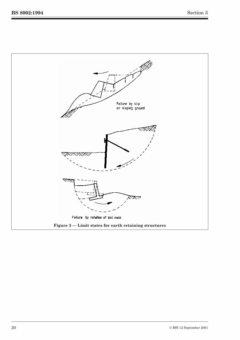
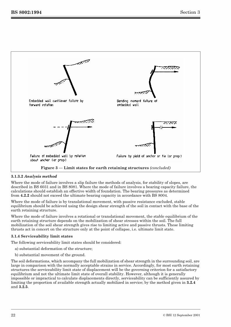
Typical ultimate limit states are depicted in Figure 3. Rupture states which are reached before collapse occurs are, for simplicity, also classified and treated as ultimate limit states. Ultimate limit states include:
a) instability of the structure or any part of it, including supports and foundations, considered as a rigid body;
b) failure by rupture of the structure or any part of it, including supports and foundations.
3.1.3 Ultimate limit states
3.1.3.1 General
The following ultimate limit states should be considered. Failure of a retaining wall as a result of:
a) instability of the earth mass, e.g. a slip failure, overturning or a rotational failure where the disturbing moments on the structure exceed the restoring moments, a translational failure where the disturbing forces (see 1.3.8) exceed the restoring forces and a bearing failure. Instability of the earth mass involving a slip failure may occur where:
1) the wall is built on sloping ground which itself is close to limiting equilibrium; or
2) the structure is underlain by a significant depth of clay whose undrained strength increases only gradually with depth; or
3) the structure is founded on a relatively strong stratum underlain by weaker strata; or
4) the structure is underlain by strata within which high pore water pressures may develop from natural or artificial sources.
b) failure of structural members including the wall itself in bending or shear;
c) excessive deformation of the wall or ground such that adjacent structures or services reach their ultimate limit state.
© BSI 12 September 2001 19
BS 8002:1994 Section 3
Figure 3 — Limit states for earth retaining structures
20 © BSI 12 September 2001
BS 8002:1994Section 3
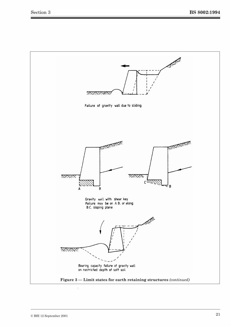
Figure 3 — Limit states for earth retaining structures (continued)
© BSI 12 September 2001 21
BS 8002:1994 Section 3
3.1.3.2 Analysis method
Where the mode of failure involves a slip failure the methods of analysis, for stability of slopes, are described in BS 6031 and in BS 8081. Where the mode of failure involves a bearing capacity failure, the calculations should establish an effective width of foundation. The bearing pressures as determined from 4.2.2 should not exceed the ultimate bearing capacity in accordance with BS 8004.
Where the mode of failure is by translational movement, with passive resistance excluded, stable equilibrium should be achieved using the design shear strength of the soil in contact with the base of the earth retaining structure.
Where the mode of failure involves a rotational or translational movement, the stable equilibrium of the earth retaining structure depends on the mobilization of shear stresses within the soil. The full mobilization of the soil shear strength gives rise to limiting active and passive thrusts. These limiting thrusts act in concert on the structure only at the point of collapse, i.e. ultimate limit state.
3.1.4 Serviceability limit states
The following serviceability limit states should be considered:
a) substantial deformation of the structure;
b) substantial movement of the ground.
The soil deformations, which accompany the full mobilization of shear strength in the surrounding soil, are large in comparison with the normally acceptable strains in service. Accordingly, for most earth retaining structures the serviceability limit state of displacement will be the governing criterion for a satisfactory equilibrium and not the ultimate limit state of overall stability. However, although it is generally impossible or impractical to calculate displacements directly, serviceability can be sufficiently assured by limiting the proportion of available strength actually mobilized in service; by the method given in 3.2.4 and 3.2.5.
Figure 3 — Limit states for earth retaining structures (concluded)
22 © BSI 12 September 2001
BS 8002:1994Section 3
The design earth pressures used for serviceability limit state calculations will differ from those used for ultimate limit state calculations only where structures are to be subjected to differing design values of external loads (generally surcharge and live loads) for the ultimate limit state and for the serviceability limit state.
3.1.5 Limit states and compatibility of deformations
The deformation of an earth retaining structure is important because it has a direct effect upon the forces on the structure, the forces from the retained soil and the forces which result when the structure moves against the soil. The structural forces and bending moments due to earth pressures reduce as deformation of the structure increases.
The maximum earth pressures on a retaining structure occur during working conditions and the necessary equilibrium calculations (see 3.2.1) are based on the assumption that earth pressures greater than fully active pressure (see 1.3.11) and less than fully passive will act on the retaining structure during service. As ultimate limit state with respect to soil pressures is approached, with sufficient deformation of the structure, the active earth pressure (see 1.3.1) in the retained soil reduces to the fully active pressure and the passive resistance (see 1.3.15) tends to increase to the full available passive resistance (see 1.3.12).
The compatibility of deformation of the structure and the corresponding earth pressures is important where the form of structure, for example a propped cantilever wall, prevents the occurrence of fully active pressure at the prop. It is also particularly important where the structure behaves as a brittle material and loses strength as deformation increases, such as an unreinforced mass gravity structure or where the soil is liable to strain softening as deformation increases.
3.1.6 Design values of parameters
These are applicable at the specified limit states in the specified design situations. All elements of safety and uncertainty should be incorporated into the design values.
The selection of design values for soil parameters should take account of:
a) the possibility of unfavourable variations in the values of the parameters;
b) the independence or interdependence of the various parameters involved in the calculation;
c) the quality of workmanship and level of control specified for the construction.
3.1.7 Applied loads
The design value for the density of fill materials, should be a pessimistic or unfavourable assessment of actual density.
For surcharges and live loadings different values may be appropriate for the differing conditions of serviceability and ultimate limit states and for different load combinations. The intention of this code of practice is to determine those earth pressures which will not be exceeded in a limit state, if external loads are correctly predicted. External loads, such as structural dead loads or vehicle surcharge loads may be specified in other codes as nominal or characteristic values. Some of the structural codes, with which this code interfaces, specify different load factors to be applied for serviceability or ultimate limit state checks and for different load combinations, see 3.2.7. Design values of loads, derived by factoring or otherwise, are intended, here, to be the most pessimistic or unfavourable loads which should be used in the calculations for the structure. Similarly, when external loads act on the active or retained side of the wall these same external loads should be derived in the same way. The soil is then treated as forming part of the whole structural system.
3.1.8 Design soil strength (see 1.3.8)
Assessment of the design values depends on the required or anticipated life of the structure, but account should be taken also of the short-term conditions which apply during and immediately following the period of construction. Single design values of soil strength should be obtained from a consideration of the representative values for peak and ultimate strength. The value so selected will satisfy, simultaneously, the considerations of ultimate and serviceability limit states. The design value should be the lower of:
a) that value of soil strength, on the stress-strain relation leading to peak strength, which is mobilized at soil strains acceptable for serviceability. This can be expressed as the peak strength reduced by a mobilization factor M as given in 3.2.4 or 3.2.5; or
b) that value which would be mobilized at collapse, after significant ground movements. This can generally be taken to be the critical state strength.
© BSI 12 September 2001 23
BS 8002:1994 Section 3
Design values selected in this way should be checked to ensure that they conform to 3.1.6. Design values should not exceed representative values of the fully softened critical state soil strength.
3.1.9 Design earth pressures
The design values of lateral earth pressure are intended to give an overestimate of the earth pressure on the active or retained side and an underestimate of the earth resistance on the passive side for small deformations of the structure as a whole, in the working state. Earth pressures reduce as fully active conditions are mobilized at peak soil strength in the retained soil, under deformations larger than can be tolerated for serviceability. As collapse threatens, the retained soil approaches a critical state, in which its strength reduces to that of loose material and the earth pressures consequently tend to increase once more to active values based on critical state strength.
The initial presumption should be that the design earth pressure will correspond to that arising from the design soil strength, see 3.1.8. But the mobilized earth pressure in service, for some walls, will exceed these values. This enhanced earth pressure will control the design, for example.
a) Where clays may swell in the retained soil zone, or be subject to the effects of compaction in layers, larger earth pressures may occur in that zone, causing corresponding resistance from the ground, propping forces, or anchor tensions to increase so as to maintain overall equilibrium.
b) Where clays may have lateral earth pressures in excess of the assessed values taking account of earth pressures prior to construction and the effects of wall installation and soil excavation or filling, the earth pressure in retained soil zones will be increased to maintain overall equilibrium.
c) Where both the wall and backfill are placed on compressible soils, differential settlement due to consolidation may lead to rotation of the wall into the backfill. This increases the earth pressures in the retained zone.
d) Where the structure is particularly stiff, for example fully piled box-shaped bridge abutments, higher earth pressures, caused, for example by compaction, may be preserved, notwithstanding that the degree of wall displacement or flexibility required to reduce retained earth pressures to their fully active values in cohesionless materials is only of the order of a rotation of 10–3 radians.
In each of these cases, mobilized soil strengths will increase as deformations continue, so the unfavourable earth pressure conditions will not persist as collapse approaches.
The design earth pressures are derived from design soil strengths using the usual methods of plastic analysis, with earth pressure coefficients (see 1.3.9) given in this code of practice being based on Kerisel & Absi (1990). The same design earth pressures are used in the default condition for the design of structural sections, see 3.2.7.
3.2 Design method
3.2.1 Equilibrium calculations
In order to determine the geometry of the retaining wall, for example the depth of penetration of an embedded wall (see 1.3.10), equilibrium calculations should be carried out for carefully formulated design situations. The design calculations relate to a free-body diagram of forces and stresses for the whole retaining wall. The design calculations should demonstrate that there is global equilibrium of vertical and horizontal forces, and of moments. Separate calculations should be made for different design situations.
The structural geometry of the retaining wall and the equilibrium calculations should be determined from the design earth pressures derived from the design soil strength using the appropriate earth pressure coefficients.
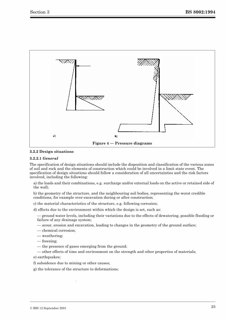
Design earth pressures will lead to active and passive pressure diagrams of the type shown in Figure 4. The earth pressure distribution should be checked for global equilibrium of the structure. Horizontal forces equilibrium and moment equilibrium will give the prop force in Figure 4a) and the location of the point of reversed stress conditions near the toe in Figure 4b). Vertical forces equilibrium should also be checked.
24 © BSI 12 September 2001
BS 8002:1994Section 3
3.2.2 Design situations
3.2.2.1 General
The specification of design situations should include the disposition and classification of the various zones of soil and rock and the elements of construction which could be involved in a limit state event. The specification of design situations should follow a consideration of all uncertainties and the risk factors involved, including the following:
a) the loads and their combinations, e.g. surcharge and/or external loads on the active or retained side of the wall;
b) the geometry of the structure, and the neighbouring soil bodies, representing the worst credible conditions, for example over-excavation during or after construction;
c) the material characteristics of the structure, e.g. following corrosion;
d) effects due to the environment within which the design is set, such as:
— ground water levels, including their variations due to the effects of dewatering, possible flooding or failure of any drainage system;— scour, erosion and excavation, leading to changes in the geometry of the ground surface;— chemical corrosion;— weathering;— freezing;— the presence of gases emerging from the ground;— other effects of time and environment on the strength and other properties of materials;
e) earthquakes;
f) subsidence due to mining or other causes;
g) the tolerance of the structure to deformations;
Figure 4 — Pressure diagrams
© BSI 12 September 2001 25
BS 8002:1994 Section 3
h) the effect of the new structure on existing structures or services and the effect of existing structures or services on the new structure;
i) for structures resting on or near rock, the consideration of:
— interbedded hard and soft strata;— faults, joints and fissures;— solution cavities such as swallow holes or fissures, filled with soft material, and continuing solution processes.
3.2.2.2 Unplanned excavation and surcharge
In checking the stable equilibrium and soil deformation, retaining walls should be designed assuming a depth of unplanned excavation in front of the wall. The depth of the excavation should be not less than 10 % of the total height retained for cantilever walls or of the height retained below the lowest support level for propped or anchored walls, but the depth of the excavation may be limited to 0.5 m. This recommendation for an additional excavation as a design criterion is to provide for unforeseen and accidental events. The recommended values should be reviewed for each design; more adverse values should be adopted in particular critical or uncertain conditions but smaller values may be adopted where adverse conditions are beyond reasonable doubt.Foreseeable excavations such as service or drainage trenches in front of a retaining wall, which may be required at some stage in the life of the structure, should be treated as a planned excavation. Actual excavation beyond the planned depth is outside the design considerations of this code.
In addition to the design check for unplanned excavation a further but separate check should be carried out for stable equilibrium and soil deformation with the retaining wall designed for a design surcharge load as recommended in 3.3.4.
3.2.2.3 Water pressure regime
The water pressure regime used in the design should be the most onerous that is considered to be reasonably possible.
3.2.3 Calculations based on total and effective stress parameters
The changes in loading associated with the construction of a retaining wall may result in changes in the strength of the ground in the vicinity of the wall. Where the mass permeability of the ground is low these changes of strength take place over some time and therefore the design should consider conditions in both the short- and long-term. Which condition will be critical depends on whether the changes in load applied to the soil mass cause an increase or decrease in soil strength. The long-term condition is likely to be critical where the soil mass undergoes a net reduction in load as a result of excavation, such as adjacent to a cantilever wall. Conversely where the soil mass is subject to a net increase in loading, such as beneath the foundation of a gravity or reinforced stem wall at ground level, the short-term condition is likely to be critical for stability. When considering long-term earth pressures and equilibrium, allowance should be made for changes in ground water conditions and pore water pressure regime which may result from the construction of the works or from other agencies.
Calculations for long-term conditions require shear strength parameters to be in terms of effective stress and should take account of a range of water pressures based on considerations of possible seepage flow conditions within the earth mass. Effective stress methods can also be used to assess the short-term conditions provided the pore water pressures developed during construction are known. A total stress method of analysis may be used to assess the short-term conditions in clays and soils of low permeability, but an inherent assumption of this method is that there will be no change in the soil strength as a result of the changes in load caused by the construction. For granular materials and soils of high permeability all excess pore water pressure will dissipate rapidly so that the relevant strength is always the drained strength and the earth pressures and equilibrium calculations are always in terms of effective stresses.
3.2.4 Design using total stress parameters
The retaining wall should be designed to be in equilibrium when based on a mobilized undrained design clay strength (design cu) which does not exceed the representative undrained strength divided by a mobilization factor M. The value of M should not be less than 1.5 if wall displacements are required to be less than 0.5 % of wall height. The value of M should be larger than 1.5 for clays which require large strains to mobilize their peak strength.
26 © BSI 12 September 2001
BS 8002:1994Section 3
3.2.5 Design using effective stress parameters
The retaining wall should be designed to be in equilibrium mobilizing a soil strength the lesser of:
a) the representative peak strength of the soil divided by a factor M = 1.2:
that is:
(3)
(4)
or
b) the representative critical state strength of the soil.
This will ensure that for soils which are medium dense or firm the wall displacements in service will be limited to 0.5 % of the wall height. The mobilization factor of 1.2 should be used in conjunction with the “unplanned” excavation in front of the wall, the minimum surcharge loading and the water pressure regime, see 3.2.2.2 and 3.2.2.3.
A more detailed analysis of displacement should be performed where tighter criteria are to be applied or for soft or loose soils. The criteria a) and b), taken together, should provide a sufficient reserve of safety against small unforeseen loads and adverse conditions.
In stiff clays subject to cycles of strain, such as through seasonal variation of pore water pressure, the long-term peak strength may deteriorate to the critical state strength. The requirements of a) and b) above are sufficiently cautious to accommodate this possibility.
3.2.6 Design values of wall friction, base friction and undrained wall adhesion
These should be derived from the representative strength determined in accordance with 2.2.8, using the same mobilization factors as for the adjacent soil.
The design value of the friction or adhesion to be mobilized at an interface with the structure should be the lesser of:
a) the representative value determined by test as described in 2.2.8 if such test results are available; or
b) 75 % of the design shear strength to be mobilized in the soil itself, that is using:
Since for the soil mass:
(7)
this is equivalent to:
(8)
similarly, in total stress analysis:
(9)
design tan � = 0.75 × design tan �´ (5)
design cw = 0.75 × design cu (6)
design tan ��representative tan ��max
M---------------------------------------------------------------------=
design c� respresentative c�M
-------------------------------------------------=
design tan ��representative tan ��max
1.2---------------------------------------------------------------------=
design �respresentative ��--------------------------------------------------- 2
3---�
design cwrepresentative cu------------------------------------------------ 0,5 after taking M 1.5= =
© BSI 12 September 2001 27
BS 8002:1994 Section 3
The friction or adhesion, which can be mobilized in practice, is generally less than the value deduced on the basis of soil sliding against the relevant surface. It is unlikely for example, that a cantilever wall will remain at constant elevation while the active soil zone subsides creating full downward wall friction on the retained side, and the passive zone heaves creating full upward wall friction on the excavated side. It is more likely that the wall would move vertically with one or other soil zone, reducing friction on that side, and thereby attaining vertical force equilibrium. The 25 % reduction in the design shear strength in b) above makes an allowance for this possibility. Further reductions, and even the elimination of wall friction or its reversal, may be necessary when soil structure interaction is taken into account. Wall friction on the retained or active side should be excluded when the wall is capable of penetrating deeper, due to the vertical thrust imparted by inclined anchors on an embedded wall, by structural loads on a basement wall, or where a clay soil may heave due to swelling during outward movement of the wall. Wall friction on the passive side should be excluded when the wall is prevented from sinking but the adjacent soil may fail to heave, due for example to settlement of loose granular soils induced by cyclic loads, or when the wall is free to move upwards with the passive soil zone, as may happen with buried anchor blocks.
3.2.7 Design to structural codes
The earth pressures to be used in structural design calculations should be determined using methods set out in 3.1.9 and 3.2.2, taking into account, where applicable, the effect of compaction stresses (see 3.3.3.6). These earth pressures are the most unfavourable that are likely to occur. They occur under working conditions.
The earth pressures which occur at ultimate limit state are less.
The earth pressures at structural serviceability limit state and ultimate limit state will be similar for relatively rigid structure, such as mass gravity walls, because the displacement criteria will be similar.
The strength of the structural sections of the retaining wall may be determined using either permissible stress methods or by the methods use in partial factor structural codes (see 3.1.2).
3.3 Disturbing forces
3.3.1 General
The disturbing forces to be taken into account in the equilibrium calculations are the earth pressures on the active or retained side of the wall, together with loads due to the compaction of the fill (if any) behind the wall, surcharge loads, external loads and last, but by no means least, the water pressure.
3.3.2 At-rest earth pressures
The earth pressures which act on retaining walls, or parts of retaining walls, below existing ground, depend on the initial or at-rest state of stress in the ground. For an undisturbed soil at a state of rest, the ratio of the horizontal to vertical stress depends on the type of soil, its geological origin, the temporary loads which may have acted on the surface of the soil and the topography.
For soil in a state of rest, the ratio of horizontal to vertical effective stress (Ki) can be estimated by a variety of means including self-boring pressuremeter tests, laboratory determination of soil suction and empirical correlations with in situ tests including static cone and dilatometer. The value of Ki depends on the type of soil, its geological history, the topography, the temporary loads which may have acted on the ground surface and changes in ground strain or ground water regime due to natural or artificial causes.
Where there has been no lateral strain within the ground, Ki can be equated with Ko the coefficient determinable from one-dimensional consolidation and swelling tests conducted in a stress-path triaxial test using appropriate stress cycles. For normally consolidated soils, both granular and cohesive:
For overconsolidated soils, Ko is larger and may approach the passive value at shallow depths in a heavily overconsolidated clay, (see for example Lambe and Whitman, quoting Hendron and Wroth 1975).
Ki is not used directly in earth retaining structure design because the construction process always modifies this initial value. The value of Ki is however, important in assessing the degree of deformation which will be induced as the earth pressure tends towards active or passive states. In normally consolidated soil the ground deformation necessary to mobilize the active condition will be small in relation to that required to mobilize the full passive resistance, while in heavily overconsolidated soil the required ground deformation
Ko = 1 – sin �� (10)
28 © BSI 12 September 2001
BS 8002:1994Section 3
will be of similar magnitude. Additional ground deformation is necessary for the structure to approach a failure condition with the earth pressures moving further towards their limiting active and passive values.
Where a stressed support system is employed (e.g. ground anchorage) then the partial mobilization of the active state on the retained side is reversed during installation of the system and, in the zone of support, the effective stress ratio in the soil may pass through the original value of Ko and tend toward the value of Kp.
3.3.3 Active earth pressures
3.3.3.1 General
Active earth pressures are generally assumed to increase linearly with increasing depth. However there may be variations from a linear relationship as a consequence, for example, of wall flexure. This can result in reduced bending moments in the structure, where the structure is flexible. Where deformations of the retaining structure are caused by transient loads, as encountered in highway structures, locked-in moments may remain after the load has been removed. These locked-in stresses will accumulate under repeated loading. This effect will limit the application of reduced bending moments in such structures.
The design soil strength, derived in accordance with 3.1.8 should be used in evaluating the active earth pressure.
3.3.3.2 Cohesionless soils
The basic formula for active pressure is applicable in the following simple situation:
— uniform cohesionless soil;— no water pressure;— mode of deformation such that earth pressure increases linearly with depth;— uniformly distributed surcharge only.
In these restricted circumstances, the active pressure at depth z is given by:
(11)
where the earth pressure coefficient Ka is based on design values of soil parameters.
The total active thrust normal to the wall between ground level and depth z is then:
(12)
If there is static ground water beneath a water table at depth zw, then for z > zw
(13)
where
(14)
an Ka �z q+� �=
Pan Ka � z2
2----- Ka qz+=
�an Ka�v� u+=
u �w z zw–� �=
© BSI 12 September 2001 29
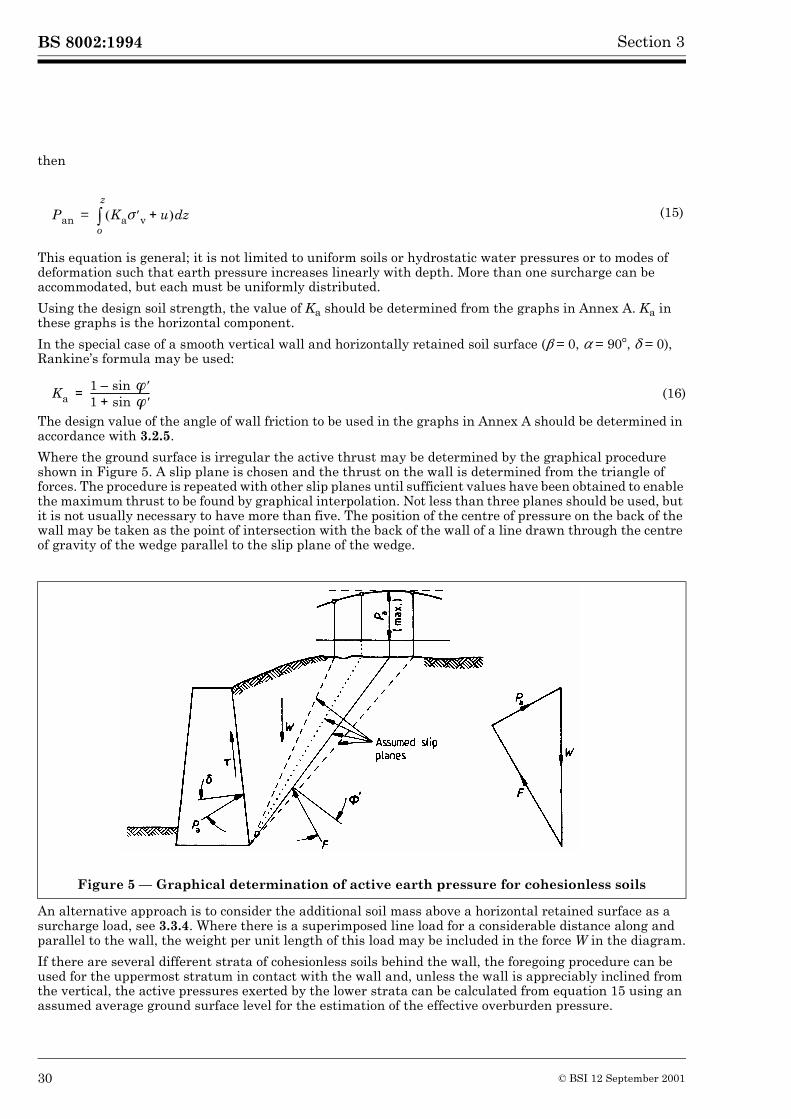
BS 8002:1994 Section 3
then
This equation is general; it is not limited to uniform soils or hydrostatic water pressures or to modes of deformation such that earth pressure increases linearly with depth. More than one surcharge can be accommodated, but each must be uniformly distributed.
Using the design soil strength, the value of Ka should be determined from the graphs in Annex A. Ka in these graphs is the horizontal component.
In the special case of a smooth vertical wall and horizontally retained soil surface (� = 0, � = 90�, � = 0), Rankine’s formula may be used:
(16)
The design value of the angle of wall friction to be used in the graphs in Annex A should be determined in accordance with 3.2.5.
Where the ground surface is irregular the active thrust may be determined by the graphical procedure shown in Figure 5. A slip plane is chosen and the thrust on the wall is determined from the triangle of forces. The procedure is repeated with other slip planes until sufficient values have been obtained to enable the maximum thrust to be found by graphical interpolation. Not less than three planes should be used, but it is not usually necessary to have more than five. The position of the centre of pressure on the back of the wall may be taken as the point of intersection with the back of the wall of a line drawn through the centre of gravity of the wedge parallel to the slip plane of the wedge.
An alternative approach is to consider the additional soil mass above a horizontal retained surface as a surcharge load, see 3.3.4. Where there is a superimposed line load for a considerable distance along and parallel to the wall, the weight per unit length of this load may be included in the force W in the diagram.
If there are several different strata of cohesionless soils behind the wall, the foregoing procedure can be used for the uppermost stratum in contact with the wall and, unless the wall is appreciably inclined from the vertical, the active pressures exerted by the lower strata can be calculated from equation 15 using an assumed average ground surface level for the estimation of the effective overburden pressure.
(15)
Figure 5 — Graphical determination of active earth pressure for cohesionless soils
Pan Ka��v u+� � zdo
z
�=
Ka1 ��sin–1 sin ��+---------------------------=
30 © BSI 12 September 2001
BS 8002:1994Section 3
3.3.3.3 Clay soils
Clays in the long term behave as granular soils exhibiting friction and dilation. If a secant �� value is selected, the procedures described in 3.3.3.2 will apply. If tangent parameters (c�,���) are to be used, then the active thrust between ground level and depth z is given by:
where
Equation 17 can be applied generally for layered soils and irrespective of the mode of deformation, provided fully active earth pressures are relevant. When a clay soil is subjected to rapid shearing (see 1.3.16) then it may be assumed to behave in an undrained condition. A total stress analysis may then be carried out using design values of the undrained shear strength cu and the undrained wall adhesion cw:
where
and cw is the design value of undrained wall adhesion, see 3.2.6.
In some circumstances tension cracks may develop in the retained clay soil. These may become water-filled immediately following a rain storm. If there is a tension crack care is necessary in the use of cw. The expression �v – Kac cu cannot be taken as negative. Where an increase in soil volume is possible, e.g. following deflection of the wall or shrinkage of clay during periods of dry weather, any free water will, in time, be absorbed by the clay with consequent swelling and reduction of shear strength towards the critical state value.
It is usually convenient and practical to consider the loads on retaining walls as imposed by one of two types of clay, normally consolidated clays and overconsolidated clays. These have different stress histories and therefore exhibit different pore water pressure characteristics during shear.
3.3.3.4 Normally and lightly overconsolidated clay
For normally consolidated and lightly overconsolidated clay it is satisfactory to use the design undrained shear strength cu, because in a total stress analysis, the short-term condition is usually critical, except for excavation in front of embedded walls.
The strength of normally consolidated clays is often sensitive to disturbance. Where there is a possibility of excessive disturbance to the retained material (e.g. by construction procedures such as nearby piling operations) then the design should be based on the undrained shear strength of soil remoulded at its natural water content.
Where the possibility of a tension crack filled with water to ground level is precluded the design should be checked for the estimated equilibrium conditions using effective shear strength soil parameters in the retained soil with c� = 0.
3.3.3.5 Overconsolidated clay
During shearing of an overconsolidated clay negative excess pore water pressures are induced by dilation. These gradually reach equilibrium but in so doing the clay will draw in water, swell and soften.
The short-term stability of an overconsolidated clay whose mass permeability is low, of the order of 10–8 m/s or less, and where the consequences of failure are not severe, the pressures applied by a clay may be based on the design undrained shear strength (cu). The possible influence of a water-filled tension crack should be taken into account.
(17)
(18)
(19)
(20)
Pan ���an u–� � zdo
z
�=
���an Ka��v 2c � K a–=
Pan ��v Kaccu–� � zdo
z
�=
Kac 2 1c wcu-------+� �
� �=
© BSI 12 September 2001 31
BS 8002:1994 Section 3
Where the mass permeability is not of a low order and particularly where the overconsolidated clay is fissured or weathered, the design should assume that negative pore water pressures, in the retained soil, will reach equilibrium in a short time; the active earth pressure should be calculated using an effective stress analysis.
Where the ground surface is irregular or the wall is not vertical, an estimate of the actual earth pressure may be obtained by the procedure used for cohesionless soils, see 3.3.3.2. The graphical construction is shown in Figure 6. The position of the centre of pressure on the back of the wall may be taken as the point of intersection, with the back of the wall, of a line drawn through the centre of gravity of the wedge parallel to the failure surface of the wedge.
3.3.3.6 Compaction earth pressures
A substantial overconsolidation ratio can be imposed on a backfill by compaction. Such compaction may lead to an in situ stress ratio over the upper part of the wall which is significantly greater than the value of Ko for a normally consolidated clay and can even lead to values nearly as high as Kp. These pressures can cause deformations and movement of a structure designed for active pressures and, where heavy compaction of a backfill is essential, account should be taken of these pressures in design. Guidance on the pressure associated with the compaction of backfill, is given by Broms (1971), Ingold (1979), Symons and Murray (1988), Clayton and Symons (1992) and TRRL publications LR766, LR946 and RR192.
3.3.3.7 Weak rocks
The active thrust pressures from weak rocks can vary over a wide range. Knowledge of the relation between the rock geometry, in particular the discontinuities, and the excavation geometry is essential. An analysis in terms of effective stress is generally applicable, since most weak or weathered rocks possess a relatively high mass permeability, but the influence of water pressure in discontinuities should be taken into account and particularly where fine gouge in bedding planes may lead to a perched water table. The rock should be considered to have the potential to fail either as a rock mass or on planes of discontinuity.
General guidance cannot be given because of the widely varying nature of weak rocks. Special field and analytical investigations will be required in the design of any major structure.
For minor structures it is generally adequate to take a conservative approach and treat weak rocks as being composed of interlocking granular fragments, with an effective angle of friction. The angle of friction depends upon the inter-fragment friction and upon the particle size of the grains and the mineralogy of the rock. Table 4 gives effective angles of friction for rocks which can be treated as composed of granular fragments.
For major structures an examination of exposures of the rock type should be carried out to determine in particular the stable slope angle and propensity to weathering or degradation.
32 © BSI 12 September 2001
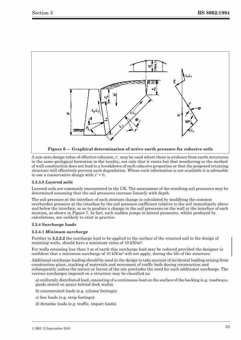
BS 8002:1994Section 3
A non-zero design value of effective cohesion, c�, may be used where there is evidence from earth structures in the same geological formation in the locality, not only that it exists but that weathering or the method of wall construction does not lead to a breakdown of such cohesive properties or that the proposed retaining structure will effectively prevent such degradation. Where such information is not available it is advisable to use a conservative design with c� = 0.
3.3.3.8 Layered soils
Layered soils are commonly encountered in the UK. The assessment of the resulting soil pressures may be determined assuming that the soil pressures increase linearly with depth.
The soil pressure at the interface of each stratum change is calculated by modifying the common overburden pressure at the interface by the soil pressure coefficient relative to the soil immediately above and below the interface, so as to produce a change in the soil pressures on the wall at the interface of each stratum, as shown in Figure 7. In fact, such sudden jumps in lateral pressures, whilst produced by calculations, are unlikely to exist in practice.
3.3.4 Surcharge loads
3.3.4.1 Minimum surcharge
Further to 3.2.2.2 the surcharge load to be applied to the surface of the retained soil in the design of retaining walls, should have a minimum value of 10 kN/m2.
For walls retaining less than 3 m of earth this surcharge load may be reduced provided the designer is confident that a minimum surcharge of 10 kN/m2 will not apply, during the life of the structure.
Additional surcharge loading should be used in the design to take account of incidental loading arising from construction plant, stacking of materials and movement of traffic both during construction and subsequently unless the nature or layout of the site precludes the need for such additional surcharge. The various surcharges imposed on a structure may be classified as:
a) uniformly distributed load, consisting of a continuous load on the surface of the backing (e.g. roadways, goods stored on quays behind dock walls);
b) concentrated loads (e.g. column footings);
c) line loads (e.g. strip footings);
d) dynamic loads (e.g. traffic, impact loads).
Figure 6 — Graphical determination of active earth pressure for cohesive soils
© BSI 12 September 2001 33
BS 8002:1994 Section 3
3.3.4.2 Uniformly distributed loads
The lateral thrust due to uniformly distributed surcharge is assumed to act at the same angle to the back of the wall as the thrust due to the earth. The surcharge pressure is considered as an initial overburden pressure at ground level.
3.3.4.3 Concentrated vertical loads and line loads
The lateral thrust induced by point or line loads acting on the retained soil should be estimated preferably by plastic analysis, using design soil strengths. The influence of line loads can be found either by analysing the plastic equilibrium of plane wedges (Pappin, 1986) or by considering safe distributions of plane stress (Bolton, 1991). The average influence of point loads, on a section of wall, can be estimated safely by considering an equivalent line load acting on that plane section, ignoring support from neighbouring sections. Elastic stress distributions may be used to estimate the vertical stress increments due to concentrated loads, but the vertical stresses should then be included in a plastic analysis using design earth pressure coefficients.
The extra thrust induced by a concentrated load may not disappear when the load is removed: more than 50 % of the effect may remain. This hysteresis is the cause of the compaction-induced stresses, see 3.3.3.6. Locked-in stresses, such as compaction stresses, will relax if the wall moves away from the compacted fill, but otherwise they should be taken into account in determining load effects on the structure. The locked-in lateral stress is a function of the greatest vertical stress previously induced at that point in the soil, Bolton (1991) offers further guidance. A reasonable estimate can be obtained by separately calculating the possible surcharge loading cases and designing for the worst case of:
a) compaction machine in place, together with locked-in stresses in the fill beneath;
b) future concentrated loads in place, in the absence of compaction-induced stresses.
3.3.4.4 Dynamic loads
Dynamic loads may be due to natural phenomena, for example by earthquakes, or may be man-made by traffic or machinery vibrations. This diversity precludes the listing of numerical criteria for such types of loading.
It is necessary first to assess qualitatively the vulnerability of the earth retaining structure to the dynamic loadings. This should establish whether the dynamic response is likely to be excessive in terms of either stress or motion. Factors requiring examination include resonance (or high dynamic amplification) and undue flexibility of the system. High dynamic amplification may occur when there is a close match between the forcing frequency and a dominant structural frequency, either for the whole system or locally within the system. It is undesirable to have closely matching frequencies for linking parts of the retaining structure system.
Loose sands, silty clays, saturated silts and flexible structures can all result in excessive displacements, even in the absence of high amplification effects. Where dynamic effects are not significant, estimates of peak lateral earth pressures may be made using the Mononobe-Okabe approach, see Seed and Whitman (1970). Flexible structures may incur excessive non-structural damage because of lateral drift during an earthquake. Where a retaining wall, sited on soft or loose soil, may be subjected to significant ground vibrations, then the structure should be provided with a stiff foundation so as to prevent excessive differential movement in the upper part of the structure.
Silts and loose- to medium-dense sands may undergo liquefaction during an earthquake. The depth of potential liquefaction should be assessed for the earthquake conditions appropriate to the site. It may be necessary to carry the foundations of the retaining wall below the liquefaction zone, or compact the soil within the zone. See Seed H.B. et al (1983) and Ishihara (1993). In dense cohesionless soils or overconsolidated clay soils, severe problems with dynamic loads occur only with severe machine vibrations or earthquakes.
Numerical design criteria are reasonably well developed for earthquakes and are included in the codes of practice applicable in seismic regions such as California and New Zealand, see Earthquake resistant regulations — A world list, IAEE (1992).
Definitive criteria for the limitation of damage to structures from vibrations from other sources, such as blast vibrations and ground motions induced by explosions and forced vibrations from rotating and impact machines are difficult to develop, although empirical and semi-empirical approaches are available. See Institution of Structural Engineers Structure-soil interaction (1977); Dowrick D.J. (1977); Blasting practice (1972); Corbett B.O. (1961); Richart F.E. (1960); Alpan I. (1961); Barkan D.D. (1962).
34 © BSI 12 September 2001
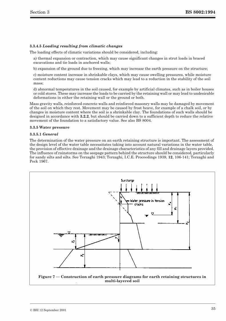
BS 8002:1994Section 3
3.3.4.5 Loading resulting from climatic changes
The loading effects of climatic variations should be considered, including:
a) thermal expansion or contraction, which may cause significant changes in strut loads in braced excavations and tie loads in anchored walls;
b) expansion of the ground due to freezing, which may increase the earth pressure on the structure;
c) moisture content increase in shrinkable clays, which may cause swelling pressures, while moisture content reductions may cause tension cracks which may lead to a reduction in the stability of the soil mass;
d) abnormal temperatures in the soil caused, for example by artificial climates, such as in boiler houses or cold stores. These may increase the loads to be carried by the retaining wall or may lead to undesirable deformations in either the retaining wall or the ground or both.
Mass gravity walls, reinforced concrete walls and reinforced masonry walls may be damaged by movement of the soil on which they rest. Movement may be caused by frost heave, for example of a chalk soil, or by changes in moisture content where the soil is a shrinkable clay. The foundations of such walls should be designed in accordance with 3.2.2, but should be carried down to a sufficient depth to reduce the relative movement of the foundation to a satisfactory value. See also BS 8004.
3.3.5 Water pressure
3.3.5.1 General
The determination of the water pressure on an earth retaining structure is important. The assessment of the design level of the water table necessitates taking into account natural variations in the water table, the provision of effective drainage and the drainage characteristics of any fill and drainage layers provided. The influence of rainstorms on the seepage pattern behind the structure should be considered, particularly for sandy silts and silts. See Terzaghi 1943; Terzaghi, I.C.E. Proceedings 1939, 12, 106-141; Terzaghi and Peck 1967.
Figure 7 — Construction of earth pressure diagrams for earth retaining structures in multi-layered soil
© BSI 12 September 2001 35
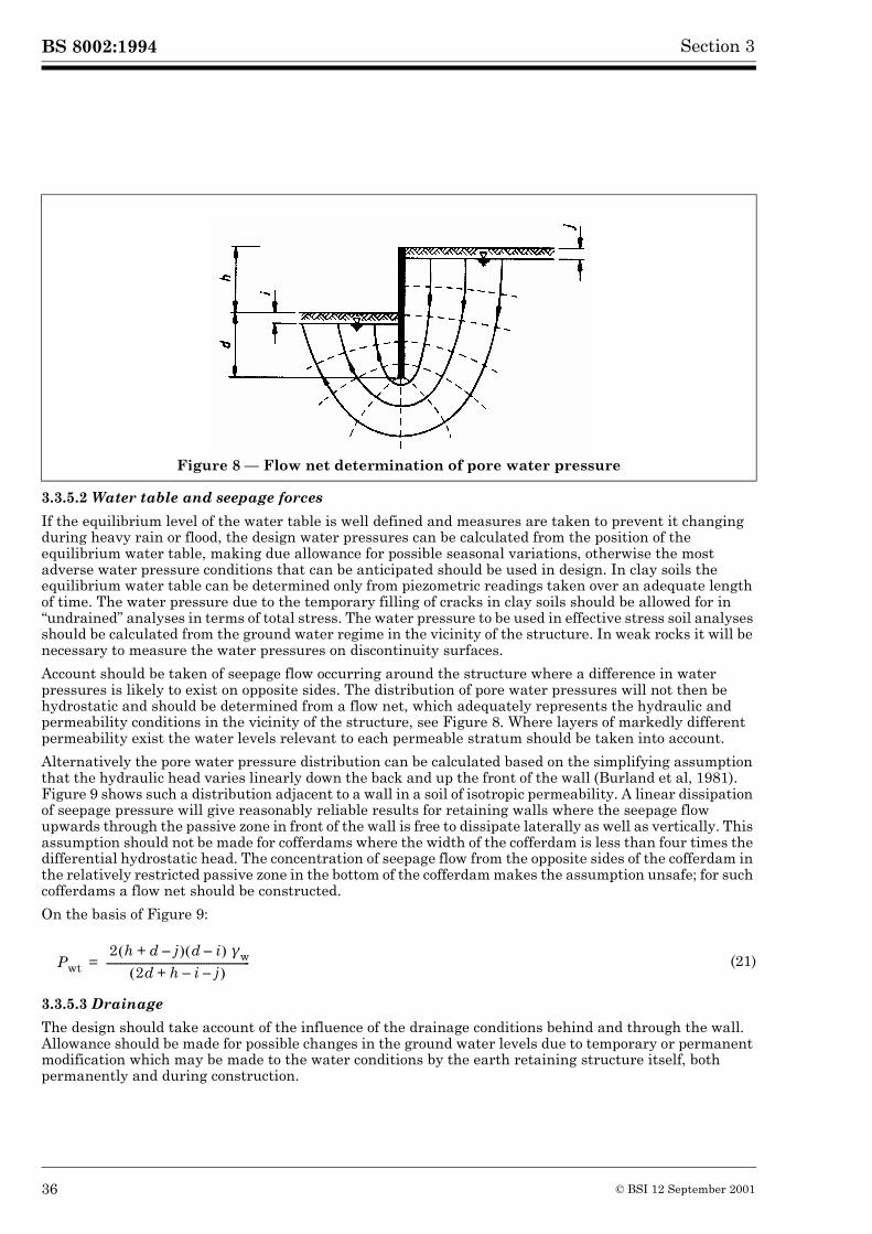
BS 8002:1994 Section 3
3.3.5.2 Water table and seepage forces
If the equilibrium level of the water table is well defined and measures are taken to prevent it changing during heavy rain or flood, the design water pressures can be calculated from the position of the equilibrium water table, making due allowance for possible seasonal variations, otherwise the most adverse water pressure conditions that can be anticipated should be used in design. In clay soils the equilibrium water table can be determined only from piezometric readings taken over an adequate length of time. The water pressure due to the temporary filling of cracks in clay soils should be allowed for in “undrained” analyses in terms of total stress. The water pressure to be used in effective stress soil analyses should be calculated from the ground water regime in the vicinity of the structure. In weak rocks it will be necessary to measure the water pressures on discontinuity surfaces.
Account should be taken of seepage flow occurring around the structure where a difference in water pressures is likely to exist on opposite sides. The distribution of pore water pressures will not then be hydrostatic and should be determined from a flow net, which adequately represents the hydraulic and permeability conditions in the vicinity of the structure, see Figure 8. Where layers of markedly different permeability exist the water levels relevant to each permeable stratum should be taken into account.
Alternatively the pore water pressure distribution can be calculated based on the simplifying assumption that the hydraulic head varies linearly down the back and up the front of the wall (Burland et al, 1981). Figure 9 shows such a distribution adjacent to a wall in a soil of isotropic permeability. A linear dissipation of seepage pressure will give reasonably reliable results for retaining walls where the seepage flow upwards through the passive zone in front of the wall is free to dissipate laterally as well as vertically. This assumption should not be made for cofferdams where the width of the cofferdam is less than four times the differential hydrostatic head. The concentration of seepage flow from the opposite sides of the cofferdam in the relatively restricted passive zone in the bottom of the cofferdam makes the assumption unsafe; for such cofferdams a flow net should be constructed.
On the basis of Figure 9:
3.3.5.3 Drainage
The design should take account of the influence of the drainage conditions behind and through the wall. Allowance should be made for possible changes in the ground water levels due to temporary or permanent modification which may be made to the water conditions by the earth retaining structure itself, both permanently and during construction.
Figure 8 — Flow net determination of pore water pressure
(21)Pwt 2 h d j–+� � d i–� ���w
2d h i j––+� �-----------------------------------------------------------=
36 © BSI 12 September 2001
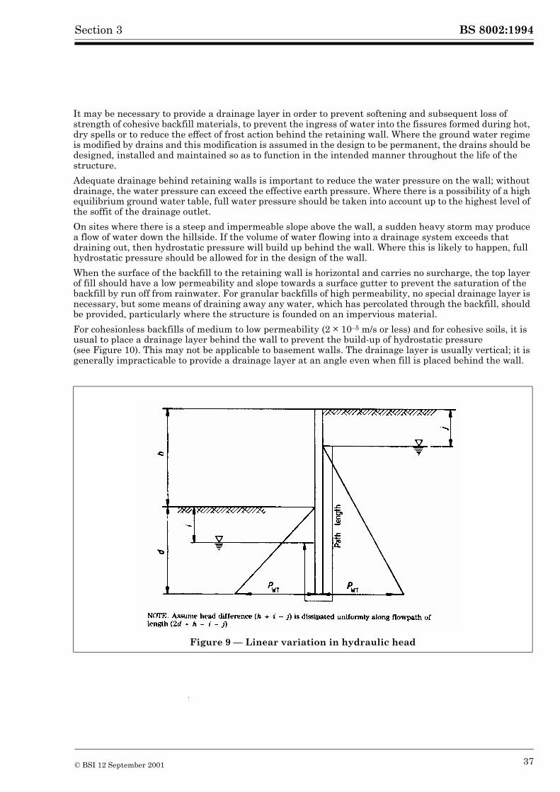
BS 8002:1994Section 3
It may be necessary to provide a drainage layer in order to prevent softening and subsequent loss of strength of cohesive backfill materials, to prevent the ingress of water into the fissures formed during hot, dry spells or to reduce the effect of frost action behind the retaining wall. Where the ground water regime is modified by drains and this modification is assumed in the design to be permanent, the drains should be designed, installed and maintained so as to function in the intended manner throughout the life of the structure.
Adequate drainage behind retaining walls is important to reduce the water pressure on the wall; without drainage, the water pressure can exceed the effective earth pressure. Where there is a possibility of a high equilibrium ground water table, full water pressure should be taken into account up to the highest level of the soffit of the drainage outlet.
On sites where there is a steep and impermeable slope above the wall, a sudden heavy storm may produce a flow of water down the hillside. If the volume of water flowing into a drainage system exceeds that draining out, then hydrostatic pressure will build up behind the wall. Where this is likely to happen, full hydrostatic pressure should be allowed for in the design of the wall.
When the surface of the backfill to the retaining wall is horizontal and carries no surcharge, the top layer of fill should have a low permeability and slope towards a surface gutter to prevent the saturation of the backfill by run off from rainwater. For granular backfills of high permeability, no special drainage layer is necessary, but some means of draining away any water, which has percolated through the backfill, should be provided, particularly where the structure is founded on an impervious material.
For cohesionless backfills of medium to low permeability (2 � 10–5 m/s or less) and for cohesive soils, it is usual to place a drainage layer behind the wall to prevent the build-up of hydrostatic pressure (see Figure 10). This may not be applicable to basement walls. The drainage layer is usually vertical; it is generally impracticable to provide a drainage layer at an angle even when fill is placed behind the wall.
Figure 9 — Linear variation in hydraulic head
© BSI 12 September 2001 37
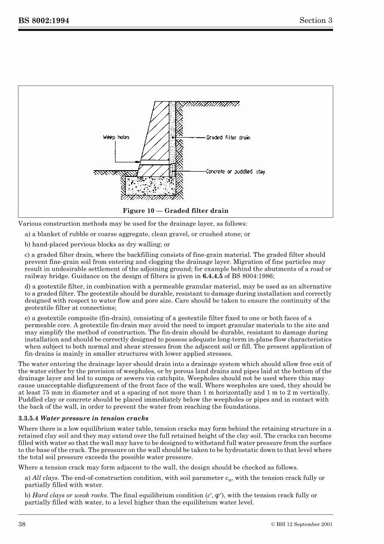
BS 8002:1994 Section 3
Various construction methods may be used for the drainage layer, as follows:
a) a blanket of rubble or coarse aggregate, clean gravel, or crushed stone; or
b) hand-placed pervious blocks as dry walling; or
c) a graded filter drain, where the backfilling consists of fine-grain material. The graded filter should prevent fine-grain soil from entering and clogging the drainage layer. Migration of fine particles may result in undesirable settlement of the adjoining ground; for example behind the abutments of a road or railway bridge. Guidance on the design of filters is given in 6.4.4.5 of BS 8004:1986;
d) a geotextile filter, in combination with a permeable granular material, may be used as an alternative to a graded filter. The geotextile should be durable, resistant to damage during installation and correctly designed with respect to water flow and pore size. Care should be taken to ensure the continuity of the geotextile filter at connections;
e) a geotextile composite (fin-drain), consisting of a geotextile filter fixed to one or both faces of a permeable core. A geotextile fin-drain may avoid the need to import granular materials to the site and may simplify the method of construction. The fin-drain should be durable, resistant to damage during installation and should be correctly designed to possess adequate long-term in-plane flow characteristics when subject to both normal and shear stresses from the adjacent soil or fill. The present application of fin-drains is mainly in smaller structures with lower applied stresses.
The water entering the drainage layer should drain into a drainage system which should allow free exit of the water either by the provision of weepholes, or by porous land drains and pipes laid at the bottom of the drainage layer and led to sumps or sewers via catchpits. Weepholes should not be used where this may cause unacceptable disfigurement of the front face of the wall. Where weepholes are used, they should be at least 75 mm in diameter and at a spacing of not more than 1 m horizontally and 1 m to 2 m vertically. Puddled clay or concrete should be placed immediately below the weepholes or pipes and in contact with the back of the wall, in order to prevent the water from reaching the foundations.
3.3.5.4 Water pressure in tension cracks
Where there is a low equilibrium water table, tension cracks may form behind the retaining structure in a retained clay soil and they may extend over the full retained height of the clay soil. The cracks can become filled with water so that the wall may have to be designed to withstand full water pressure from the surface to the base of the crack. The pressure on the wall should be taken to be hydrostatic down to that level where the total soil pressure exceeds the possible water pressure.
Where a tension crack may form adjacent to the wall, the design should be checked as follows.
a) All clays. The end-of-construction condition, with soil parameter cu, with the tension crack fully or partially filled with water.
b) Hard clays or weak rocks. The final equilibrium condition (c�,���), with the tension crack fully or partially filled with water, to a level higher than the equilibrium water level.
Figure 10 — Graded filter drain
38 © BSI 12 September 2001
BS 8002:1994Section 3
3.3.5.5 Waterfront conditions
Maritime structures are subject to the effects of waves, surge tides and flood conditions. Overtopping of the wall may occur, resulting in inundation of the retained soils, followed by a rapid drop of water level on exposed face. The design should take account of the resulting hydraulic pressures and the possible build up of ground water levels behind the structure.
The maximum out-of-balance hydrostatic head which may result from a tidal variation, should be used in the design, particularly where the wall can be overtopped. See particularly 4.7.3.6 and section 5 of BS 6349-1:1984.
3.4 Resistance to movement
3.4.1 General
Resistance to the disturbing forces on earth retaining structures may be provided by the mobilized passive soil pressures of an embedded wall, or by a combination of base resistance and passive soil pressure on a gravity or free-standing structure. In addition resistance may be provided by struts and walings in trench excavations, by ground anchorages and by the stability of the building in basement construction.
3.4.2 Passive earth resistance
3.4.2.1 General
Passive earth resistance is assumed to increase linearly with increasing depth. However variations from a linear relationship may arise as a consequence, for example, of wall flexure or where the wall has an extensive depth of penetration below dredge or excavation level in front of the wall.
In evaluating the resistance to lateral movement for design purposes, the design soil strength, derived in accordance with 3.1.8, should be used. In assessing the passive resistance the design should incorporate the obligatory “unplanned” excavation, see 2.2.2.
3.4.2.2 Cohesionless soils
The basic formula for passive resistance is applicable in the following simple situation:
— uniform cohesionless soil;— no water pressure;— mode of deformation such that earth resistance increases linearly with depth;— uniformly distributed surcharge only.
In these restricted circumstances, the passive pressure at depth z is given by:
The total passive thrust normal to the wall between ground level and depth z is then:
If there is static ground water beneath a water table at depth zw, then for z > zw:
where
(22)
(23)
(24)
(25)
�pn Kp�v=
K= p � �z q+� �
Ppn Kp �z2
2----- Kpqz+=
�pn Kp �v u–� � u+=
Kp�v� u+� �=
u � w z zw–� �=
© BSI 12 September 2001 39
BS 8002:1994 Section 3
then
This equation is general; it is not limited to uniform soils nor hydrostatic water pressures nor to modes of deformation such that earth resistance increases linearly with depth. More than one surcharge can be accommodated, but each must be uniformly distributed.
Values of the horizontal component of Kp are given in Annex A. A further approach is presented by Sokolovski (1965).
In the special case of a smooth vertical wall and horizontally retained soil surface (� = 0, � = 0), the passive earth resistance coefficient Kp is given by the Rankine’s formula:
This formula gives the same results as the graph for Kp in Annex A, with
3.4.2.3 Clay soils
3.4.2.3.1 General
Clays, in the long term, behave as granular soils exhibiting friction and dilation. If a secant � value is selected the procedures described in 3.4.2.2 apply and the values of Kp in Annex A are applicable. If tangent parameters (c�, ��) are to be used, then the passive resistance between ground level and depth z is given by:
where
and the values of the horizontal component of Kp are given in Annex A. Equation 28 can be applied generally for layered soils and irrespective of the mode of deformation, provided passive resistance is relevant. When a clay soil is subjected to rapid shearing it may be assumed to behave in an undrained condition. A total stress analysis may then be carried out using design values of the undrained shear strength cu:
where
and cw is the design value of undrained wall adhesion, see 3.2.6.
3.4.2.3.2 Normally and lightly overconsolidated clay
As with active pressures, the passive resistance of clay soils is considered separately for normally and lightly overconsolidated clays and for overconsolidated clays.
Under long-term stress, the positive pore water pressures induced by the shear stresses will dissipate, leading to consolidation and an increase in strength of the soil. This will be accompanied by wall movement. The most onerous condition for equilibrium will generally exist immediately after construction and the design should be based on a total stress analysis using design values of the undrained shear strength cu.
(26)
(27)
(28)
(29)
(30)
(31)
Ppn Kp���v u+� � zd
0
z
�=
Kp1 ���sin+1 ���sin–---------------------------=
��
���------- 0 ��, 0.= =
Ppn ���pn u+� � zdo
z
�=
��*pn Kp��
�v 2c� Kp+=
Ppn ��v Kpccu+� � zdo
z
�=
Kpc 2 1cwcu------+� �
� �=
40 © BSI 12 September 2001
BS 8002:1994Section 3
In some circumstances the strength of the clay will reduce with time and therefore a check of the design should be made using effective shear strength parameters.
Where excessive disturbance to the soil may occur during construction or through the influence of local works (e.g. by driving of high displacement piles) the design should be based on the undrained shear strength of the soil remoulded at its natural water content.
Reliance should not be placed upon the passive resistance of sensitive clays except in special cases, e.g. cofferdams.
3.4.2.3.3 Overconsolidated clay
In an overconsolidated clay non-uniform strain of the clay may exist within the passive mass resulting in varying soil strength values. Generally, it is only practicable to make allowances for the complexity of these characteristics by using an approximate method of analysis.
Two cases are considered.
a) Case 1. This applies to structures where there is no change in ground level in front of the wall from that existing for a considerable period of time prior to construction. The equilibrium state of stress in the passive soil mass is not significantly disturbed. An effective stress analysis will take account of the loss of strength created by the dissipation of the negative pore water pressures induced by shear strain.
If laboratory test data is available then an appropriate design value for c� may be used but in selecting a c� value for design purposes account should be taken of possible loss of strength associated with wall deformations.
For short-term temporary works in an overconsolidated clay of known low mass permeability of the order of 10–8 m/s or less, a total stress analysis may be used based on the results of undrained tests on the soil. For the upper layers of soil the undrained strength of the clay should be assumed to reduce to zero at the surface.
The design values of the wall friction parameters or the undrained wall adhesion should be determined in accordance with 3.2.6.
b) Case 2. This applies to structures where excavation lowers the ground level in front of the wall below the existing for a considerable period of time prior to construction. The soil subject to a passive pressure in this case undergoes loss of strength due to the release in overburden pressure. This reduction in stress is in a vertical direction, whereas the horizontal stress present within the undisturbed soil will be augmented by the pressure imposed by the wall.
As in case 1 an effective stress analysis should be carried out. Effective shear strength parameters should be used and the recommendations regarding the use of c� are also applicable.
3.4.3 Weak rocks
The pattern of discontinuities, e.g. joints, fissures, etc., which are present within the rock mass is important in determining the passive resistance available in weak rocks as it is when assessing the active pressures. The comments and recommendations relating to active pressures in 3.3.3.7 are relevant and applicable also to passive resistance.
3.4.4 Layered soils
The soil pressures, at the interfaces in a layered soil profile, are calculated from the common overburden pressure by applying the relevant passive earth resistance coefficients for each stratum, as described in 3.3.3.8 for active pressures. A change in the soil resistance thus occurs at each interface. Examples of the estimation of passive earth resistance diagrams for various strata combinations are given in Figure 7.
3.4.5 Water pressures and seepage forces
The recommendations for water pressure and seepage forces for active pressures also apply to the passive resistance of clay soils. As for active pressures, see 3.3.5, the most adverse groundwater conditions that can reasonably be anticipated should be used in the estimation of passive resistance. The influence of upward seepage within the passive zone of soil is important. It can reduce the effective overburden pressure in the extreme almost to zero.
© BSI 12 September 2001 41

42 blank
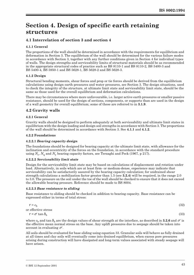
BS 8002:1994
Section 4. Design of specific earth retaining structures 4
4.1 Interrelation of section 3 and section 4
4.1.1 General
The proportions of the wall should be determined in accordance with the requirements for equilibrium and deformation in Section 3. The equilibrium of the wall should be determined for the various failure modes in accordance with Section 3, together with any further conditions given in Section 4 for individual types of walls. The design strengths and serviceability limits of structural materials should be as recommended in the appropriate structural codes of practice such as BS 8110-1 and BS 8110-2, BS 5400-3 and BS 5400-4, BS 5950-1 and BS 5628-1, BS 5628-2 and BS 5628-3.
4.1.2 Design
Structural bending moments, shear forces and prop or tie forces should be derived from the equilibrium calculations using design earth pressures and water pressures, see Section 3. The design situations, used to check the integrity of the structure, at ultimate limit state and serviceability limit state, should be the same as those used for the overall equilibrium and deformation calculations.
There may be circumstances where more unfavourable, i.e. larger active earth pressures or smaller passive resistance, should be used for the design of sections, components, or supports than are used in the design of a wall geometry for overall equilibrium; some of these are referred to in 3.1.9.
4.2 Gravity walls
4.2.1 General
Gravity walls should be designed to perform adequately at both serviceability and ultimate limit states in equilibrium with the design loading and design soil strengths in accordance with Section 3. The proportions of the wall should be determined in accordance with Section 3. See 4.1.1 and 4.1.2.
4.2.2 Foundations
4.2.2.1 Bearing capacity design
The foundations should be designed for bearing capacity at the ultimate limit state, with allowance for the inclination and eccentricity of the forces on the foundation, in accordance with the standard procedure using Nc, Nq and Ny bearing capacity factors, see Terzaghi and Peck (1967, p 217).
4.2.2.2 Serviceability limit state
Design for the serviceability limit state may be based on calculations of displacement and rotation under load. Alternatively, in soils which are at least firm- or medium-dense, experience may indicate that serviceability can be satisfactorily assured by the bearing capacity calculation; for undrained shear strength calculations a mobilization factor greater than 1.5 (see 3.2.4) will be required, in the range 2.0 to 3.0. The pressure on the soil under the toe of the wall should be checked to ensure that it does not exceed the allowable bearing pressure. Reference should be made to BS 8004.
4.2.2.3 Base resistance to sliding
Base resistance to sliding should be checked in addition to bearing capacity. Base resistance can be expressed either in terms of total stress:
where cb and tan �b are the design values of shear strength at the interface, as described in 3.2.6 and � � is the effective mean normal stress on the base. Any uplift pressures due to seepage should be taken into account in evaluating � ��
All soils should be evaluated for base sliding using equation 33. Granular soils will behave as fully drained at all times and clay soils will eventually come into drained equilibrium, when excess pore pressures arising during construction will have dissipated and long-term values associated with steady seepage will have arisen.
� = cb (32)or effective stress� = ���tan��b (33)
© BSI 12 September 2001 43
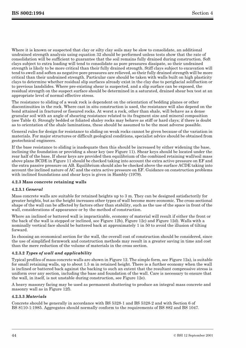
BS 8002:1994 Section 4
Where it is known or suspected that clay or silty clay soils may be slow to consolidate, an additional undrained strength analysis using equation 32 should be performed unless tests show that the rate of consolidation will be sufficient to guarantee that the soil remains fully drained during construction. Soft clays subject to extra loading will tend to consolidate as pore pressures dissipate, so their undrained strength is likely to be more critical than their fully drained strength. Stiff clays subject to excavation will tend to swell and soften as negative pore pressures are relieved, so their fully drained strength will be more critical than their undrained strength. Particular care should be taken with walls built on high plasticity clays to determine whether residual slip surfaces already exist in the clay due to periglacial solifluction or to previous landslides. Where pre-existing shear is suspected, and a slip surface can be exposed, the residual strength on the suspect surface should be determined in a saturated, drained shear box test at an appropriate level of normal effective stress.
The resistance to sliding of a weak rock is dependent on the orientation of bedding planes or other discontinuities in the rock. Where cast in situ construction is used, the resistance will also depend on the bond attained in fractured or fissured rocks. At worst a rock, other than shale, will behave as a dense granular soil with an angle of shearing resistance related to its fragment size and mineral composition (see Table 4). Strongly bedded or foliated shaley rocks may behave as stiff or hard clays; if there is doubt as to orientation of the shale laminations, these should be assumed to be the most adverse possible.
General rules for design for resistance to sliding on weak rocks cannot be given because of the variation in materials. For major structures or difficult geological conditions, specialist advice should be obtained from geotechnical engineers.
If the base resistance to sliding is inadequate then this should be increased by either widening the base, inclining the foundation or providing a shear key (see Figure 11). Shear keys should be located under the rear half of the base. If shear keys are provided then equilibrium of the combined retaining wall/soil mass above plane BCDE in Figure 11 should be checked taking into account the extra active pressure on EF and the extra passive pressure on AB. Equilibrium should also be checked above the surface ACDE taking into account the inclined nature of AC and the extra active pressure on EF. Guidance on construction problems with inclined foundations and shear keys is given in Hambly (1979).
4.2.3 Mass concrete retaining walls
4.2.3.1 General
Mass concrete walls are suitable for retained heights up to 3 m. They can be designed satisfactorily for greater heights, but as the height increases other types of wall become more economic. The cross-sectional shape of the wall can be affected by factors other than stability, such as the use of the space in front of the wall, considerations of appearance or by the method of construction.
Where an inclined or battered wall is impracticable, economy of material will result if either the front or the back of the wall is stepped or inclined, see Figure 12b), Figure 12c) and Figure 12d). Walls with a nominally vertical face should be battered back at approximately 1 in 50 to avoid the illusion of tilting forward.
In choosing an economical section for the wall, the overall cost of construction should be considered, since the use of simplified formwork and construction methods may result in a greater saving in time and cost than the mere reduction of the volume of materials in the cross section.
4.2.3.2 Types of wall and applicability
Typical profiles of mass concrete walls are shown in Figure 12. The simple form, see Figure 12a), is suitable for small retaining walls, up to about 1.5 m in retained height. There is a further economy when the wall is inclined or battered back against the backing to such an extent that the resultant compressive stress is uniform over any section, including the base and foundation of the wall. Care is necessary to ensure that the wall, in itself, is not unstable during construction, see Figure 12e).
A heavy masonry facing may be used as permanent shuttering to produce an integral mass concrete and masonry wall as in Figure 12f).
4.2.3.3 Materials
Concrete should be generally in accordance with BS 5328-1 and BS 5328-2 and with Section 6 of BS 8110-1:1985. Aggregates should normally conform to the requirements of BS 882 and BS 1047.
44 © BSI 12 September 2001
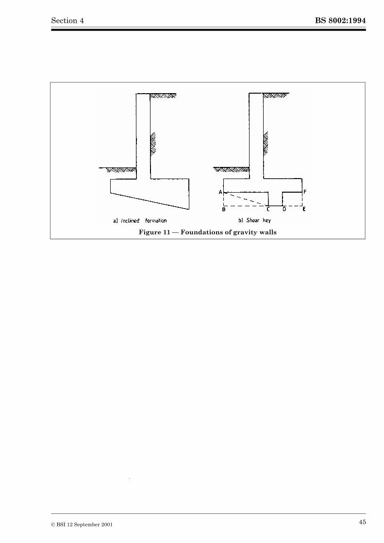
BS 8002:1994Section 4
Figure 11 — Foundations of gravity walls
© BSI 12 September 2001 45
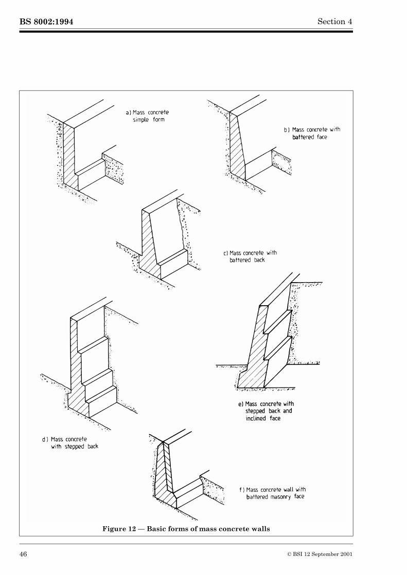
BS 8002:1994 Section 4
Figure 12 — Basic forms of mass concrete walls
46 © BSI 12 September 2001
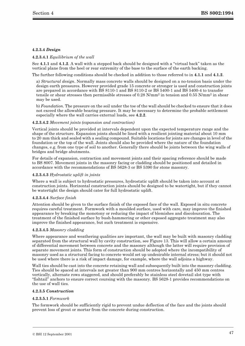
BS 8002:1994Section 4
4.2.3.4 Design
4.2.3.4.1 Equilibrium of the wall
See 4.1.1 and 4.1.2. A wall with a stepped back should be designed with a “virtual back” taken as the vertical plane from the heel or rear extremity of the base to the surface of the earth backing.
The further following conditions should be checked in addition to those referred to in 4.1.1 and 4.1.2.
a) Structural design. Normally mass concrete walls should be designed on a no-tension basis under the design earth pressures. However provided grade 15 concrete or stronger is used and construction joints are prepared in accordance with BS 8110-1 and BS 8110-2 or BS 5400-1 and BS 5400-4 to transfer tensile or shear stresses then permissible stresses of 0.28 N/mm2 in tension and 0.55 N/mm2 in shear may be used.
b) Foundation. The pressure on the soil under the toe of the wall should be checked to ensure that it does not exceed the allowable bearing pressure. It may be necessary to determine the probable settlement especially where the wall carries external loads, see 4.2.2.
4.2.3.4.2 Movement joints (expansion and contraction)
Vertical joints should be provided at intervals dependent upon the expected temperature range and the shape of the structure. Expansion joints should be lined with a resilient jointing material about 10 mm to 20 mm thick and sealed with a sealing compound. Suitable locations for joints are changes in level of the foundation or the top of the wall. Joints should also be provided where the nature of the foundation changes, e.g. from one type of soil to another. Generally there should be joints between the wing walls of bridges and bridge abutments.
For details of expansion, contraction and movement joints and their spacing reference should be made to BS 8007. Movement joints in the masonry facing or cladding should be positioned and detailed in accordance with the recommendations of BS 5628-3 or BS 5390 for stone masonry.
4.2.3.4.3 Hydrostatic uplift in joints
Where a wall is subject to hydrostatic pressures, hydrostatic uplift should be taken into account at construction joints. Horizontal construction joints should be designed to be watertight, but if they cannot be watertight the design should cater for full hydrostatic uplift.
4.2.3.4.4 Surface finish
Attention should be given to the surface finish of the exposed face of the wall. Exposed in situ concrete requires careful treatment. Formwork with a moulded surface, used with care, may improve the finished appearance by breaking the monotony or reducing the impact of blemishes and discolouration. The treatment of the finished surface by bush-hammering or other exposed aggregate treatment may also improve the finished appearance, but such treatment is expensive.
4.2.3.4.5 Masonry cladding
Where appearance and weathering qualities are important, the wall may be built with masonry cladding separated from the structural wall by cavity construction, see Figure 13. This will allow a certain amount of differential movement between concrete and the masonry although the latter will require provision of separate movement joints. This form of construction should be adopted where the incompatibility of masonry used as a structural facing to concrete would set up undesirable internal stress; but it should not be used where there is a risk of impact damage, for example, where the wall adjoins a highway.
Wall ties should be cast into the concrete retaining wall and subsequently built into the masonry cladding. Ties should be spaced at intervals not greater than 900 mm centres horizontally and 450 mm centres vertically, alternate rows staggered, and should preferably be stainless steel dovetail slot type with “fishtail” anchors to ensure correct coursing with the masonry. BS 5628-1 provides recommendations on the use of wall ties.
4.2.3.5 Construction
4.2.3.5.1 Formwork
The formwork should be sufficiently rigid to prevent undue deflection of the face and the joints should prevent loss of grout or mortar from the concrete during construction.
© BSI 12 September 2001 47
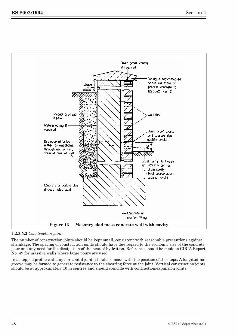
BS 8002:1994 Section 4
4.2.3.5.2 Construction joints
The number of construction joints should be kept small, consistent with reasonable precautions against shrinkage. The spacing of construction joints should have due regard to the economic size of the concrete pour and any need for the dissipation of the heat of hydration. Reference should be made to CIRIA Report No. 49 for massive walls where large pours are used.
In a stepped profile wall any horizontal joints should coincide with the position of the steps. A longitudinal groove may be formed to generate resistance to the shearing force at the joint. Vertical construction joints should be at approximately 10 m centres and should coincide with contraction/expansion joints.
Figure 13 — Masonry clad mass concrete wall with cavity
48 © BSI 12 September 2001
BS 8002:1994Section 4
4.2.3.5.3 Concreting
Concrete of low strength, such as grades C7.5 and C10 of BS 5328-1, will normally be satisfactory provided it is properly compacted to attain the necessary design density. The water/cement ratio should be low, consistent with adequate workability to obtain the necessary compaction. The design or selection of a concrete mix should provide the necessary minimum cement content required for durability. The cement content should not be less than shown in Table 6.2 and Table 6.3 of BS 8110-1:1985. If the concrete is exposed to attack by sulfates reference should be made to Table 6.1 of BS 8110-1985. Where there is likely to be severe attack from the constituents of ground water, it may be necessary to provide additional protection to the back of the wall. In waterfront structures the wall should have adequate resistance to chloride attack and may need to be provided with a waterproof protection.
4.2.3.5.4 Masonry facing and cladding
Where a structural masonry facing is to be incorporated or a masonry cladding is to be built as part of the retaining wall, the minimum quality of the masonry unit and the mortar designation required for durability should be in accordance with the recommendations of BS 5628-3 and BS 5390 for stone masonry. The choice of masonry unit and mortar designation to be used will depend upon a number of factors including exposure, whether protective detailing to the masonry such as coping and damp-proof course systems are used and if effective drainage and waterproofing to the retaining face are incorporated. Where clay bricks of quality FN and MN are used it may be necessary to use mortar containing sulfate-resisting cement (see also 4.2.4.2.1, 4.2.4.2.2 and 4.2.4.2.3).
4.2.4 Unreinforced masonry retaining walls
4.2.4.1 General
Unreinforced masonry is suitable for small retaining walls, especially where the finished appearance is important; such masonry requires minimal construction plant. A simple stem wall, is suitable for small retained heights, up to 1.5 m; for greater heights, a stepped or buttressed wall as in Figure 14 may be appropriate.
The design and construction of unreinforced masonry should conform to BS 5628-1 and BS 5628-3. The selection and detailing of stone masonry is given in BS 5390.
4.2.4.2 Materials
4.2.4.2.1 Bricks and brickwork
Brick masonry units should conform to the appropriate British Standards as follows:
Clay bricks of quality FL, FN, ML, or MN to BS 3921:1985, calcium silicate bricks of class 3 or stronger to BS 187:1978 or concrete bricks of minimum strength 15 N/mm2 to BS 6073-1:1981 and BS 6073-2:1981 may be used provided that the following protective details are incorporated into the wall:
a) a brick or slate damp-proof course at the base of the wall and above ground level conforming to BS 743. Other damp-proof course materials may be used if they can be shown to be suitable for application; and
b) effective waterproofing treatment on and drainage to the retaining (i.e. back) face of the wall; and
c) an effective coping with drips which throws water clear of the exposed wall surface; copings should be frost resistant; and
d) a continuous impervious damp-proof course below the coping, (slates, tiles and damp-proof course bricks are unsuitable).
Calcium silicate (sand-lime and flint-lime) bricks BS 187
Clay bricks BS 3921
Dimensions of bricks of special shapes and sizes BS 4729
Precast concrete masonry units BS 6073-1
Clay and calcium silicate modular bricks BS 6649
© BSI 12 September 2001 49
BS 8002:1994 Section 4
Where protective detailing is not used or where there is a risk of saturated brickwork being subjected to freezing, frost-resistant clay bricks (FL and FN quality), or calcium silicate bricks of class 4 or stronger should be used. Where moderately frost resistant clay bricks (ML and MN quality) are proposed in such situations, the manufacturer’s advice should be sought. Concrete bricks should be of minimum strength 30 N/mm2 and have adequate cement content to ensure durability.
Concrete bricks should not be used where sufficiently aggressive sulfate ground conditions exist unless they are protected or have specifically been manufactured for the purpose.
BS 5628-3 gives recommendations for the selection and use of brick masonry.
4.2.4.2.2 Other masonry units
When masonry units other than bricks are used these should conform to the appropriate British Standards:
Protective detailing to walling may be required and some types of masonry unit may not be suitable for use in aggressive sulfate conditions. BS 5628-3 and BS 5390 for stone masonry give recommendations for the selection and use of materials.
4.2.4.2.3 Mortars
Mortars to be used should be selected in accordance with BS 5628-3 and BS 5390 for stone masonry. The choice of mortar designation should be made principally on the basis of structural requirements, where these apply, and upon durability considerations.
Where damp-proof course (dpc) bricks are used in brickwork construction they should be laid in mortar designation (i) and it is advisable to use the same mortar for brickwork below the level of the dpc bricks. Where cappings to brick masonry are used mortar designation (i) should be used with clay bricks, mortar designation (ii) with calcium silicate bricks and mortar designations (i) or (ii) with concrete bricks.
Figure 14 — Stepped and buttressed retaining walls in unreinforced masonry
Stone masonry BS 5390Precast concrete masonry units BS 6073-1Reconstructed stone masonry units BS 6457
50 © BSI 12 September 2001
BS 8002:1994Section 4
Where masonry units contain high levels of soluble salts and the walls are likely to remain wet for long periods of time, for example when wall exposure to wind-driven rain is exceptionally high, the mortar should be selected with care. Where clay bricks of either FN or MN quality (see BS 3921) are used in these exposure conditions the use of mortar containing sulfate-resisting cement throughout the wall construction should be considered.
Sulfates in sufficient quantities to be damaging may be present in the ground, ground water, aggregates and backfill; protective detailing to masonry where necessary or the use of mortar containing sulfate-resisting cement should be considered.
4.2.4.2.4 Wall ties
Where wall ties are required these should be specified in accordance with BS 5628-1.
4.2.4.3 Design
4.2.4.3.1 Equilibrium of the wall
See 4.2.1 and 4.2.2.
4.2.4.3.2 Structural design
The structural design of the walls should be in accordance with BS 5628-1.
4.2.4.3.3 Movement joints
Movement joints should be incorporated as recommended in BS 5628-3. Where buttressed walls are used, a buttress should be provided each side of a joint.
4.2.4.4 Construction
4.2.4.4.1 General
The general construction and workmanship of unreinforced mass masonry walls should be in accordance with BS 5628-3 and BS 5390 as appropriate.
4.2.4.4.2 Waterproofing
Unreinforced masonry walls should be provided with a waterproofing membrane to the retaining (i.e back) face of the wall. The type of membrane to be used will depend upon the nature of the retained material and whether there will be a permanent head of ground water behind the wall. Waterproofing membranes should be adequately protected prior to and during backfilling.
Where movement joints are incorporated, water bars may be required at these joints if ground water conditions warrant. Water bars should not interfere with the free action of movement joints.
4.2.5 Reinforced soil
Retaining structures constructed with reinforcement embedded in the retained soil have advantages in embankments because the resulting vertical or steep faces, as compared with battered slopes, lead to a reduction in the extent of land required. Reference should be made to BS 80063) for detailed information on the design and construction of structures incorporating reinforced soil.
4.2.6 Gabions
4.2.6.1 General
Gabions are large cages or baskets usually of steel wire or square welded mesh, rectangular in shape, filled with stone and used to build retaining walls, revetments and anti-erosion works, see Figure 15 and Figure 16. They can also be made of wickerwork, bamboo slats, nylon or polypropylene, but there are reported instances of fire damage to gabion walls constructed from flammable materials.
3) In preparation.
© BSI 12 September 2001 51
BS 8002:1994 Section 4
4.2.6.2 Types of wall and applicability
The permeability and flexibility of gabions make them suitable where the retained material is likely to be saturated and where the bearing quality of the soil is poor. Wire mesh gabions are of two forms: baskets, which are used for walls, and mattresses which are used for revetments and the lining of river and channel banks.
The basic shape of gabion retaining walls is trapezoidal, but the outer and inner faces may be straight or stepped, the latter being more common.
The width of the horizontal tread of the steps should not exceed the depth of the gabion. Walls may have plane outer faces, preferably built to a batter for appearance and to increase the resistance to overturning. Similarly walls with stepped faces should be tilted towards the backfill. Counterforts or buttresses may be incorporated in the construction.
In large walls where the cross section is greater than 4 m wide, an economy can be made by using a cellular form of construction. The outer and inner gabion faces are tied by bulkheads of gabions and the cells between them filled with stone. The size and shape of the cells should be proportioned to achieve internal stability.
In rivers and in tidal waters, the permeability of a gabion wall is an advantage since water in the backfill during falling levels, can drain freely. The nature of the backfill may necessitate the use of a filter behind the wall, to prevent the leaching of fines. In cold climates gabions are able to resist the action of frost heave.
The life of a gabion wall is not necessarily limited by the effective life of the cage or basket if the shape of the wall is such that the stone filling remains substantially stable after failure of the cage through corrosion or abrasion of the wire mesh. If soil conditions are suitable for a rigid structure, the wall may be made permanent by grouting the gabion wall with a cement grout, but this changes the nature of the wall.
4.2.6.3 Materials
4.2.6.3.1 Hexagonal woven wire mesh
The netting is mechanically woven in a continuous sheet, to form a hexagonal mesh which can stretch or contract in two directions in its own plane so that a rectangular wire mesh box filled with quarried stone or river shingle can deform in any direction, see Figure 15.
52 © BSI 12 September 2001
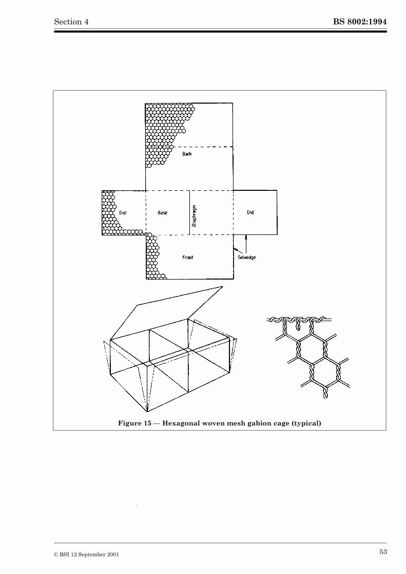
BS 8002:1994Section 4
Figure 15 — Hexagonal woven mesh gabion cage (typical)
© BSI 12 September 2001 53
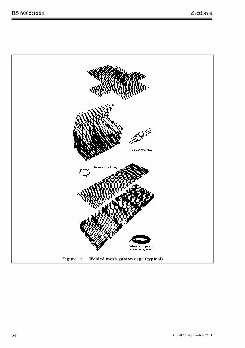
BS 8002:1994 Section 4
Figure 16 — Welded mesh gabion cage (typical)
54 © BSI 12 September 2001
BS 8002:1994Section 4
4.2.6.3.2 Welded wire mesh
Welded wire mesh is an oblong or square mesh manufactured from cold reduced steel wire, produced in accordance with BS 1052. It should be electrically welded at every intersection, giving a minimum average weld shear strength of 70 % of the minimum ultimate tensile strength of the wire.
The welded mesh is cut into panels with flush edges to suit the dimensions of the sides, top, base and diaphragms (where necessary) of the baskets, and joined together with stainless steel clips or galvanized spring steel split rings. See Figure 16. The gabions are delivered to the site flat-packed.
The rigidity or flexibility required by the designer can be achieved by selecting various sizes of wire gauge, but in general baskets made from welded mesh are less flexible than a comparable woven wire mesh basket.
4.2.6.3.3 Other meshes
Other meshes may be used such as chain link, expanded metal and pig netting. They have one or more ofthe following disadvantages:
a) tendency to unravel if one wire is broken;
b) no selvedged wire so that true rectangular shapes are difficult to form;
c) low resistance to corrosion.
Gabions made on site from rolls or sheets of mesh rarely have diaphragm panels incorporated so that structures built from them are liable to progressive failure particularly should the mesh on the outer surface be ruptured.
4.2.6.3.4 Corrosion and damage of gabions
In the use of gabions the following matters should be considered.
a) Unprotected. Uncoated wire gabions are normally used only for temporary works, but if the wire diameter is 5 mm or more, the expected life of unprotected steel may be sufficient for such gabions to be used for certain permanent works.
b) Galvanized wire. Hexagonal woven mesh gabions should be made from wire galvanized to BS 443. For welded mesh gabions, the panels of mesh which form the cages should be hot dip galvanized to BS 729 after welding. Galvanized gabions may be used where the expected life of the galvanized wire is sufficient for the intended life of the structure. The soil and water with which the structure is in contact should be assessed to determine:
1) soil resistivity;
2) redox potential;
3) dissolve salts such as chloride ion content and the total sulfate content;
4) pH value;
5) moisture content of the soil.
If the conditions are aggressive to the galvanized wire coating, the use of polyvinyl chloride (PVC) coated wire should be considered.
c) PVC coated wire. The PVC coating should conform to BS 4102. The radial thickness of the coating applied to the galvanized wire core should be a minimum of 0.25 min. The PVC should be sufficiently bonded to the galvanized wire core to prevent a capillary flow of water between the wire and the PVC coating leading to corrosion.
d) Damage by abrasion. Galvanized and PVC coated wire may be damaged by abrasion, by moving shingle in river beds and on coastal foreshores. In mountain rivers, where the heavy waterborne material usually travels along the bed, PVC gabion mesh has been satisfactory in the construction of river walls with vertical water faces but anti-scour aprons with horizontal surfaces should be avoided. Galvanized mesh is more easily abraded in these situations.
On coastal foreshores, PVC coated gabions are unsatisfactory where large shingle, or heavy abrasive material, is likely to be thrown against, or, washed over the structure by wave action.
© BSI 12 September 2001 55
BS 8002:1994 Section 4
4.2.6.3.5 Assembly of gabion units
The edges of the end panels and of the diaphragm panels, where provided, are fixed to the sides by lacing with 2.2 mm minimum binding wire, galvanized or PVC coated, to match the gabion mesh.
4.2.6.3.6 Gabion sizes
Box gabions are normally available in half metre modules in lengths of 2 m to 6 m, 1 m to 2 m wide and in depths of 0.3 m, 0.5 m and 1 m.
Boxes should, where possible, be fitted with transverse vertical diaphragm panels at 1 m centres to prevent undue distortion and stone migration.
4.2.6.3.7 Stone filling
Stone should conform to BS 5390 for hardness, crushing strength and resistance to weathering. Naturally occurring rounded stone or quarried stone are acceptable. The lower limiting size is controlled by the dimensions of the mesh, although 5 % may be down to 50 mm to 80 mm. To ensure efficient construction, the size should be as small and as uniform as possible; for marine structures 175 mm is the usual minimum. The maximum recommended size is 200 mm.
4.2.6.4 Design
4.2.6.4.1 General
Small gabion walls should be designed on the same principle as a gravity mass wall, no allowance beingmade for the strength or mass of the wire mesh, see 4.2.1 and 4.2.2. Examples of gabion walls are shownin Figure 17. The density of the stone fill should be taken as 60 % of the solid material.
4.2.6.4.2 Equilibrium of the wall
The retained soil will exert active pressure over the entire wall height, but with no hydrostatic pressure.
The cross section of a gabion wall, as a mass gravity structure, should be proportioned so that the resultant force at any horizontal section lies within the middle third of that section. The thrust exerted by the backfill on a gabion wall acts at an angle to the perpendicular to the wall. This angle can be assumed to equal the design value of �� due to the roughness of the gabion surface, which may be assumed to be a soil to soil friction surface.
When the retained soil is supported by a heel to the wall the soil may be assumed to be a part of the wall and the design assumes a virtual vertical rear face.
When calculating the resistance against sliding forward the angle of friction should be taken as that of the foundation soil in accordance with 3.2.6 and not as that between stone rubble and the soil. The gabion wall can be built on a sloped foundation to increase this resistance.
Checks should be made at selected levels above the base of a gabion wall, to ascertain that the resistance to sliding is sufficient to prevent shear failure through the wall, ignoring the effect of the wire mesh.
56 © BSI 12 September 2001
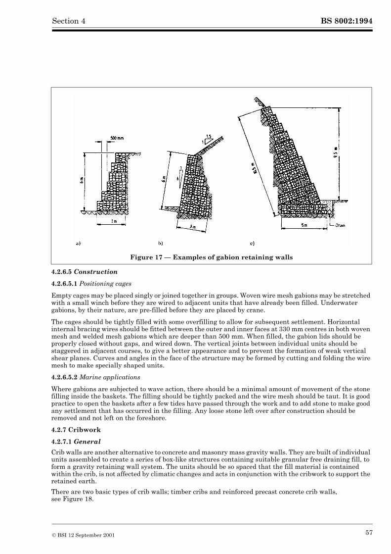
BS 8002:1994Section 4
4.2.6.5 Construction
4.2.6.5.1 Positioning cages
Empty cages may be placed singly or joined together in groups. Woven wire mesh gabions may be stretched with a small winch before they are wired to adjacent units that have already been filled. Underwater gabions, by their nature, are pre-filled before they are placed by crane.
The cages should be tightly filled with some overfilling to allow for subsequent settlement. Horizontal internal bracing wires should be fitted between the outer and inner faces at 330 mm centres in both woven mesh and welded mesh gabions which are deeper than 500 mm. When filled, the gabion lids should be properly closed without gaps, and wired down. The vertical joints between individual units should be staggered in adjacent courses, to give a better appearance and to prevent the formation of weak vertical shear planes. Curves and angles in the face of the structure may be formed by cutting and folding the wire mesh to make specially shaped units.
4.2.6.5.2 Marine applications
Where gabions are subjected to wave action, there should be a minimal amount of movement of the stone filling inside the baskets. The filling should be tightly packed and the wire mesh should be taut. It is good practice to open the baskets after a few tides have passed through the work and to add stone to make good any settlement that has occurred in the filling. Any loose stone left over after construction should be removed and not left on the foreshore.
4.2.7 Cribwork
4.2.7.1 General
Crib walls are another alternative to concrete and masonry mass gravity walls. They are built of individual units assembled to create a series of box-like structures containing suitable granular free draining fill, to form a gravity retaining wall system. The units should be so spaced that the fill material is contained within the crib, is not affected by climatic changes and acts in conjunction with the cribwork to support the retained earth.
There are two basic types of crib walls; timber cribs and reinforced precast concrete crib walls, see Figure 18.
Figure 17 — Examples of gabion retaining walls
© BSI 12 September 2001 57
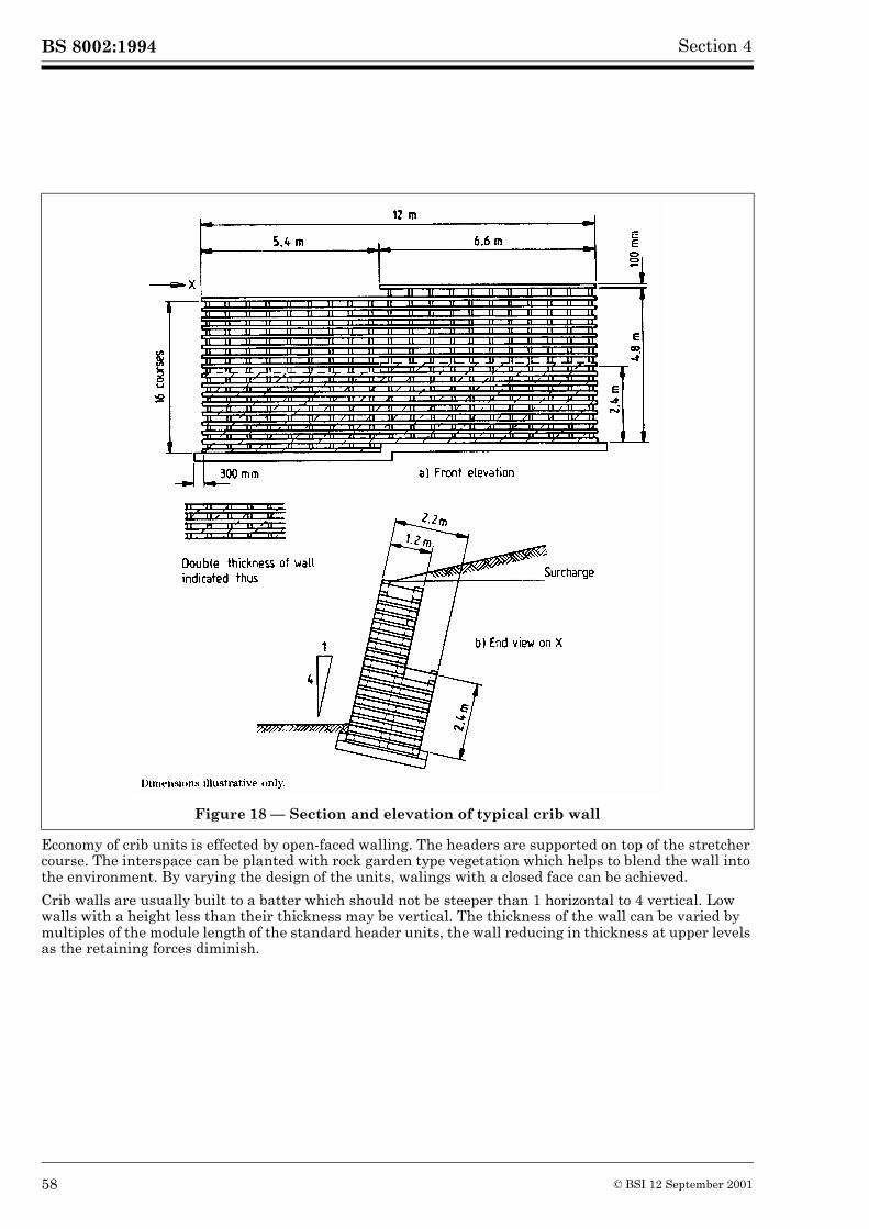
BS 8002:1994 Section 4
Economy of crib units is effected by open-faced walling. The headers are supported on top of the stretcher course. The interspace can be planted with rock garden type vegetation which helps to blend the wall into the environment. By varying the design of the units, walings with a closed face can be achieved.
Crib walls are usually built to a batter which should not be steeper than 1 horizontal to 4 vertical. Low walls with a height less than their thickness may be vertical. The thickness of the wall can be varied by multiples of the module length of the standard header units, the wall reducing in thickness at upper levels as the retaining forces diminish.
Figure 18 — Section and elevation of typical crib wall
58 © BSI 12 September 2001
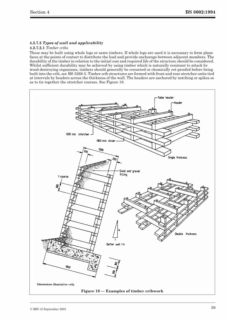
BS 8002:1994Section 4
4.2.7.2 Types of wall and applicability4.2.7.2.1 Timber cribsThese may be built using whole logs or sawn timbers. If whole logs are used it is necessary to form plane faces at the points of contact to distribute the load and provide anchorage between adjacent members. The durability of the timber in relation to the initial cost and required life of the structure should be considered. Whilst sufficient durability may be achieved by using timber which is naturally resistant to attack by wood-destroying organisms, timbers should generally be creosoted or chemically rot-proofed before being built into the crib, see BS 5268-5. Timber crib structures are formed with front and rear stretcher units tied at intervals by headers across the thickness of the wall. The headers are anchored by notching or spikes so as to tie together the stretcher courses. See Figure 19.
Figure 19 — Examples of timber cribwork
© BSI 12 September 2001 59
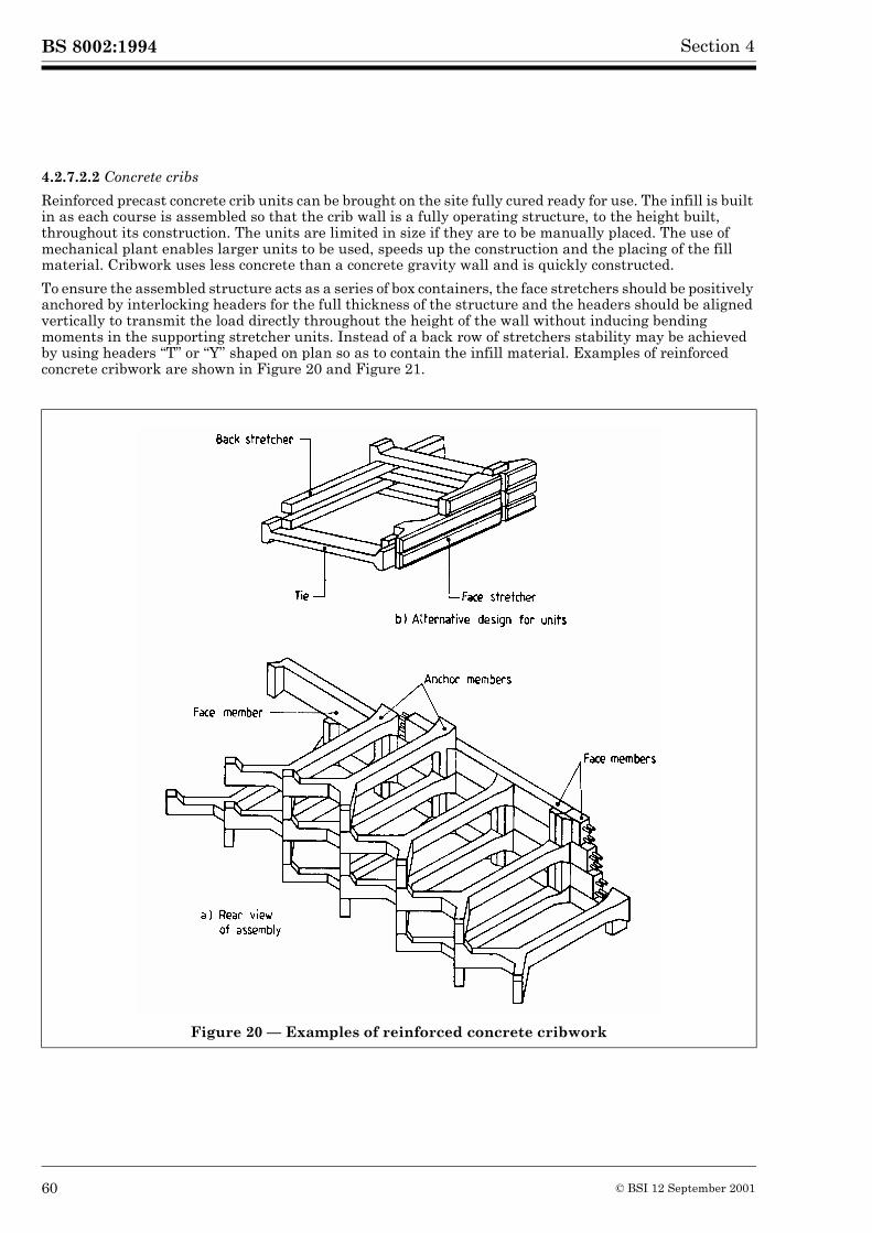
BS 8002:1994 Section 4
4.2.7.2.2 Concrete cribs
Reinforced precast concrete crib units can be brought on the site fully cured ready for use. The infill is built in as each course is assembled so that the crib wall is a fully operating structure, to the height built, throughout its construction. The units are limited in size if they are to be manually placed. The use of mechanical plant enables larger units to be used, speeds up the construction and the placing of the fill material. Cribwork uses less concrete than a concrete gravity wall and is quickly constructed.
To ensure the assembled structure acts as a series of box containers, the face stretchers should be positively anchored by interlocking headers for the full thickness of the structure and the headers should be aligned vertically to transmit the load directly throughout the height of the wall without inducing bending moments in the supporting stretcher units. Instead of a back row of stretchers stability may be achieved by using headers “T” or “Y” shaped on plan so as to contain the infill material. Examples of reinforced concrete cribwork are shown in Figure 20 and Figure 21.
Figure 20 — Examples of reinforced concrete cribwork
60 © BSI 12 September 2001
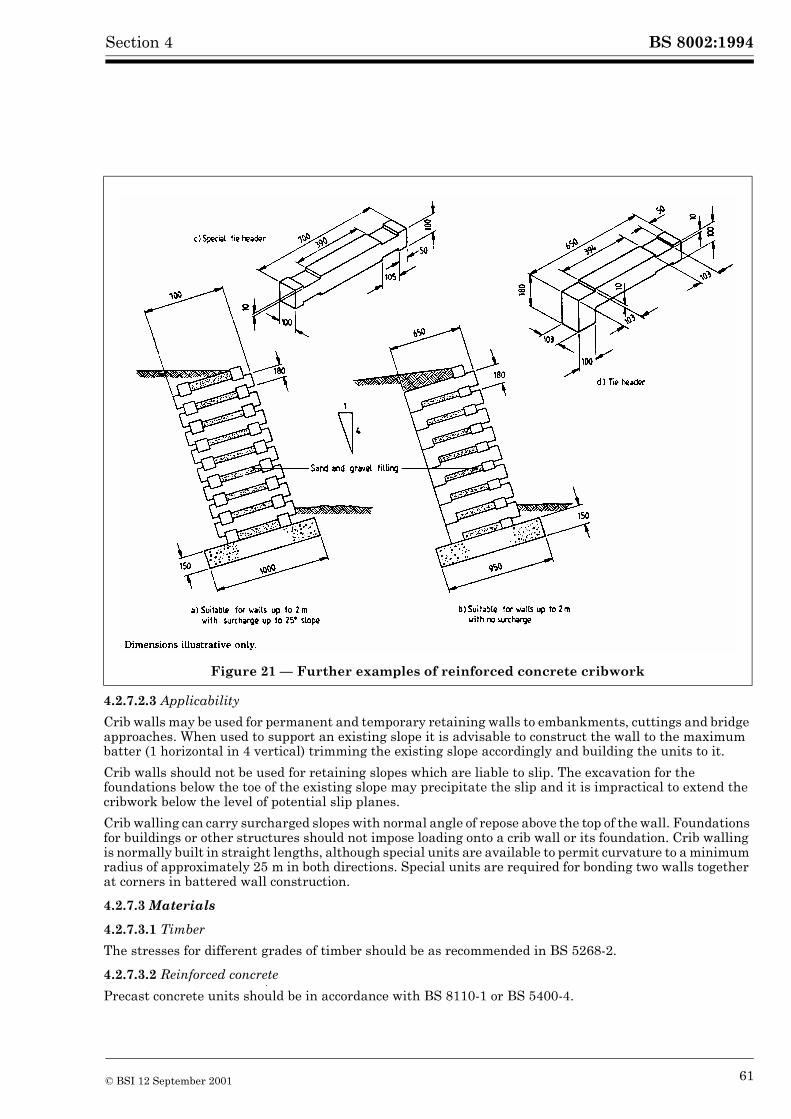
BS 8002:1994Section 4
4.2.7.2.3 Applicability
Crib walls may be used for permanent and temporary retaining walls to embankments, cuttings and bridge approaches. When used to support an existing slope it is advisable to construct the wall to the maximum batter (1 horizontal in 4 vertical) trimming the existing slope accordingly and building the units to it.
Crib walls should not be used for retaining slopes which are liable to slip. The excavation for the foundations below the toe of the existing slope may precipitate the slip and it is impractical to extend the cribwork below the level of potential slip planes.
Crib walling can carry surcharged slopes with normal angle of repose above the top of the wall. Foundations for buildings or other structures should not impose loading onto a crib wall or its foundation. Crib walling is normally built in straight lengths, although special units are available to permit curvature to a minimum radius of approximately 25 m in both directions. Special units are required for bonding two walls together at corners in battered wall construction.
4.2.7.3 Materials
4.2.7.3.1 Timber
The stresses for different grades of timber should be as recommended in BS 5268-2.
4.2.7.3.2 Reinforced concrete
Precast concrete units should be in accordance with BS 8110-1 or BS 5400-4.
Figure 21 — Further examples of reinforced concrete cribwork
© BSI 12 September 2001 61
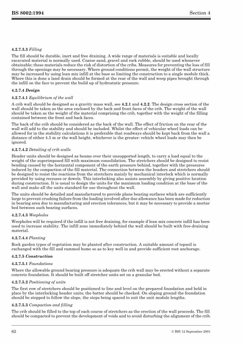
BS 8002:1994 Section 4
4.2.7.3.3 Filling
The fill should be durable, inert and free draining. A wide range of materials is suitable and locally excavated material is normally used. Coarse sand, gravel and rock rubble, should be used whenever obtainable; these materials reduce the risk of distortion of the cribs. Measures for preventing the loss of fill through the openings may be necessary. Where ground conditions permit, the weight of the wall structure may be increased by using lean mix infill at the base so limiting the construction to a single module thick. Where this is done a land drain should be formed at the rear of the wall and weep pipes brought through the infill on the face to prevent the build up of hydrostatic pressure.
4.2.7.4 Design
4.2.7.4.1 Equilibrium of the wall
A crib wall should be designed as a gravity mass wall, see 4.2.1 and 4.2.2. The design cross section of the wall should be taken as the area enclosed by the back and front faces of the crib. The weight of the wall should be taken as the weight of the material comprising the crib, together with the weight of the filling contained between the front and back faces.
The back of the crib should be considered as the back of the wall. The effect of friction on the rear of the wall will add to the stability and should be included. Whilst the effect of vehicular wheel loads can be allowed for in the stability calculations it is preferable that roadways should be kept back from the wall a distance of either 4.5 m or the wall height, whichever is the greater: vehicle wheel loads may then be ignored.
4.2.7.4.2 Detailing of crib walls
Header units should be designed as beams over their unsupported length, to carry a load equal to the weight of the superimposed fill with maximum consolidation. The stretchers should be designed to resist bending caused by the horizontal component of the earth pressure behind, together with the pressures induced by the compaction of the fill material. The connection between the headers and stretchers should be designed to resist the reactions from the stretchers mainly by mechanical interlock which is normally provided by using recesses or dowels. This interlocking also assists assembly by giving positive location during construction. It is usual to design the units for the maximum loading condition at the base of the wall and make all the units standard for use throughout the wall.
The units should be detailed and manufactured to provide plane bearing surfaces which are sufficiently large to prevent crushing failure from the loading involved after due allowance has been made for reduction in bearing area due to manufacturing and erection tolerances, but it may be necessary to provide a mortar bed between such bearing surfaces.
4.2.7.4.3 Weepholes
Weepholes will be required if the infill is not free draining, for example if lean mix concrete infill has been used to increase stability. The infill zone immediately behind the wall should be built with free-draining material.
4.2.7.4.4 Planting
Rock garden types of vegetation may be planted after construction. A suitable amount of topsoil is exchanged with the fill and rammed home so as to key well in and provide sufficient root anchorage.
4.2.7.5 Construction
4.2.7.5.1 Foundations
Where the allowable ground bearing pressure is adequate the crib wall may be erected without a separate concrete foundation. It should be built off stretcher units set on a granular bed.
4.2.7.5.2 Positioning of units
The first row of stretchers should be positioned to line and level on the prepared foundation and held in place by the interlocking header units; the batter should be checked. On sloping ground the foundation should be stepped to follow the slope, the steps being spaced to suit the unit module lengths.
4.2.7.5.3 Compaction and filling
The crib should be filled to the top of each course of stretchers as the erection of the wall proceeds. The fill should be compacted to prevent the development of voids and to avoid disturbing the alignment of the crib.
62 © BSI 12 September 2001
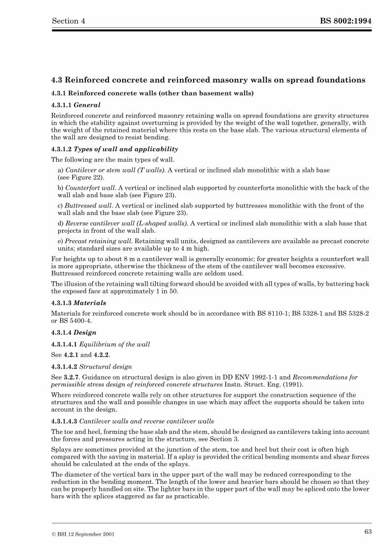
BS 8002:1994Section 4
4.3 Reinforced concrete and reinforced masonry walls on spread foundations
4.3.1 Reinforced concrete walls (other than basement walls)
4.3.1.1 General
Reinforced concrete and reinforced masonry retaining walls on spread foundations are gravity structures in which the stability against overturning is provided by the weight of the wall together, generally, with the weight of the retained material where this rests on the base slab. The various structural elements of the wall are designed to resist bending.
4.3.1.2 Types of wall and applicability
The following are the main types of wall.
a) Cantilever or stem wall (T walls). A vertical or inclined slab monolithic with a slab base(see Figure 22).
b) Counterfort wall. A vertical or inclined slab supported by counterforts monolithic with the back of the wall slab and base slab (see Figure 23).
c) Buttressed wall. A vertical or inclined slab supported by buttresses monolithic with the front of the wall slab and the base slab (see Figure 23).
d) Reverse cantilever wall (L-shaped walls). A vertical or inclined slab monolithic with a slab base that projects in front of the wall slab.
e) Precast retaining wall. Retaining wall units, designed as cantilevers are available as precast concrete units; standard sizes are available up to 4 m high.
For heights up to about 8 m a cantilever wall is generally economic; for greater heights a counterfort wall is more appropriate, otherwise the thickness of the stem of the cantilever wall becomes excessive. Buttressed reinforced concrete retaining walls are seldom used.
The illusion of the retaining wall tilting forward should be avoided with all types of walls, by battering back the exposed face at approximately 1 in 50.
4.3.1.3 Materials
Materials for reinforced concrete work should be in accordance with BS 8110-1; BS 5328-1 and BS 5328-2 or BS 5400-4.
4.3.1.4 Design
4.3.1.4.1 Equilibrium of the wall
See 4.2.1 and 4.2.2.
4.3.1.4.2 Structural design
See 3.2.7. Guidance on structural design is also given in DD ENV 1992-1-1 and Recommendations for permissible stress design of reinforced concrete structures Instn. Struct. Eng. (1991).
Where reinforced concrete walls rely on other structures for support the construction sequence of the structures and the wall and possible changes in use which may affect the supports should be taken into account in the design.
4.3.1.4.3 Cantilever walls and reverse cantilever walls
The toe and heel, forming the base slab and the stem, should be designed as cantilevers taking into account the forces and pressures acting in the structure, see Section 3.
Splays are sometimes provided at the junction of the stem, toe and heel but their cost is often high compared with the saving in material. If a splay is provided the critical bending moments and shear forces should be calculated at the ends of the splays.
The diameter of the vertical bars in the upper part of the wall may be reduced corresponding to the reduction in the bending moment. The length of the lower and heavier bars should be chosen so that they can be properly handled on site. The lighter bars in the upper part of the wall may be spliced onto the lower bars with the splices staggered as far as practicable.
© BSI 12 September 2001 63
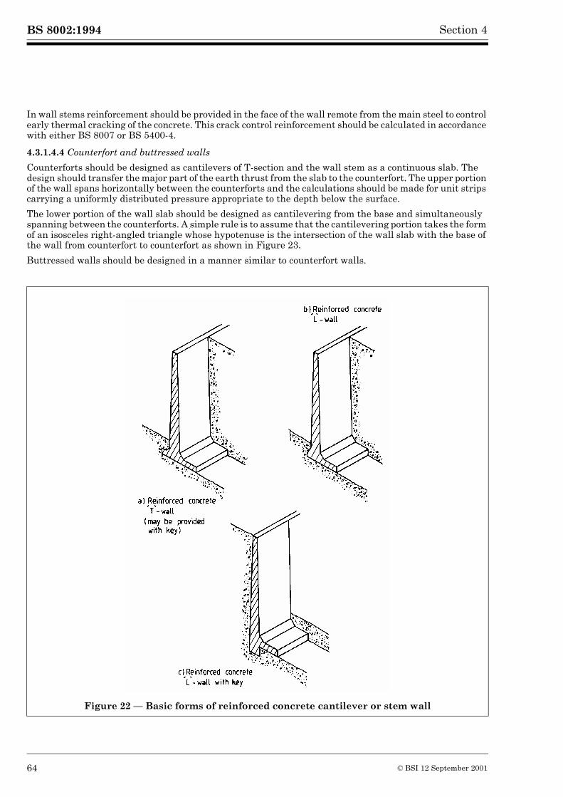
BS 8002:1994 Section 4
In wall stems reinforcement should be provided in the face of the wall remote from the main steel to control early thermal cracking of the concrete. This crack control reinforcement should be calculated in accordance with either BS 8007 or BS 5400-4.
4.3.1.4.4 Counterfort and buttressed walls
Counterforts should be designed as cantilevers of T-section and the wall stem as a continuous slab. The design should transfer the major part of the earth thrust from the slab to the counterfort. The upper portion of the wall spans horizontally between the counterforts and the calculations should be made for unit strips carrying a uniformly distributed pressure appropriate to the depth below the surface.
The lower portion of the wall slab should be designed as cantilevering from the base and simultaneously spanning between the counterforts. A simple rule is to assume that the cantilevering portion takes the form of an isosceles right-angled triangle whose hypotenuse is the intersection of the wall slab with the base of the wall from counterfort to counterfort as shown in Figure 23.
Buttressed walls should be designed in a manner similar to counterfort walls.
Figure 22 — Basic forms of reinforced concrete cantilever or stem wall
64 © BSI 12 September 2001
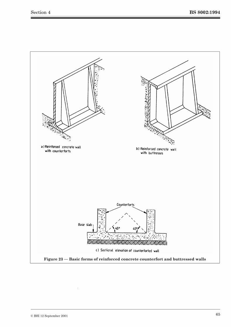
BS 8002:1994Section 4
Figure 23 — Basic forms of reinforced concrete counterfort and buttressed walls
© BSI 12 September 2001 65
BS 8002:1994 Section 4
4.3.1.4.5 Precast walls
These are usually cantilever walls, designed by the manufacturer. They are available in standard sizes dependent upon the height, angle of repose and density of the material to be retained. Foundation base design requirements particular to each site should be taken into account by designing an appropriate cast in situ foundation with holding down bolts, as necessary, see 4.2.2. Other types of precast retaining wall may consist of precast concrete slabs placed so as to bear against piles, isolated counterforts or isolated buttresses.
Non-structural precast facing panels may be used in conjunction with retaining walls to ensure that the completed structure blends with the surrounding environment. Care should be taken in the design and detailing of connections to ensure that differential stresses are not induced by the connections between the two surfaces.
4.3.1.4.6 Movement joints
Vertical joints should be provided at intervals dependent upon the type of foundation, the condition of exposure, the shape of the structure and the quantity and spacing of reinforcement. Where necessary the joints should be lined with a resilient jointing material about 10 mm to 20 mm thick and sealed with a proprietary sealing compound. Dependent upon the ground water present waterbars may also be required. Reinforcement should be curtailed each side of the joint.
Joints should be provided where the nature of the foundation changes or where steps occur in the foundations or the top of a wall. Generally there should be a joint between the wing wall of a bridge and the bridge abutment. In counterfort walls a counterfort should be provided each side of the joint. For details of expansion, contraction and movement joints and their spacing reference should be made to BS 8007.
4.3.1.4.7 Durability of wall
Attention should be given to the following matters during the design and construction of the wall.
a) Deterioration of structure. The structure should be designed for durability in accordance with Section 6 of BS 8110-1:1985. The permeability of the concrete should be low. The minimum cement content should be in accordance with Section 3 of BS 8110-1:1985.
b) Protection against corrosion. The concrete cover should be in accordance with Table 3.4 ofBS 8110-1:1985. Where the concrete is liable to attack from constituents of the ground water or where the wall is to be damp-proof, the back of the retaining wall and abutments should be painted with a suitable bituminous material or covered with self-adhesive plastic sheathing or otherwise provided with a waterproofing membrane. Waterproofing membranes should be adequately protected prior to and during backfilling.
c) Attack by ground or saline water. Chemical analysis of any ground water present should be made to assess its sulfate content, so that a suitable concrete mix may be designed in accordance with Table 6.1 of BS 8110-1:1985 in order to achieve a high resistance.
Walls subject to splashing or intermittent wetting by saline water should have adequate resistance to or protection from chloride attack and may need protection by a waterproof membrane.
d) Detailing. Attention should be given to the detailing of appropriate drips at the top of the retaining wall, weepholes and other points where water may accumulate so that the unsightly blemishes on the exposed concrete surface due to rainwater and waterborne detritus, may be avoided.
4.3.1.4.8 Masonry cladding
Reinforced concrete retaining walls may be built with masonry cladding where appearance and weathering qualities are design factors. Where masonry is used as a cladding reference should be made to Figure 13 and 4.2.3.4.2, 4.2.3.4.5, 4.2.3.5.4 and 4.2.4.2.
4.3.1.5 Construction
4.3.1.5.1 Construction joints
Construction joints should be kept to a minimum. Generally to facilitate construction there should be a joint between the base, or splay and the wall stem, with additional horizontal joints in the wall stem to suit the lifts of the formwork. Vertical joints should be positioned at points of minimum shear and at approximately 10 m centres. Reinforcement should pass through the joints. Reference may be made to BS 8007 for details of types of joints.
66 © BSI 12 September 2001
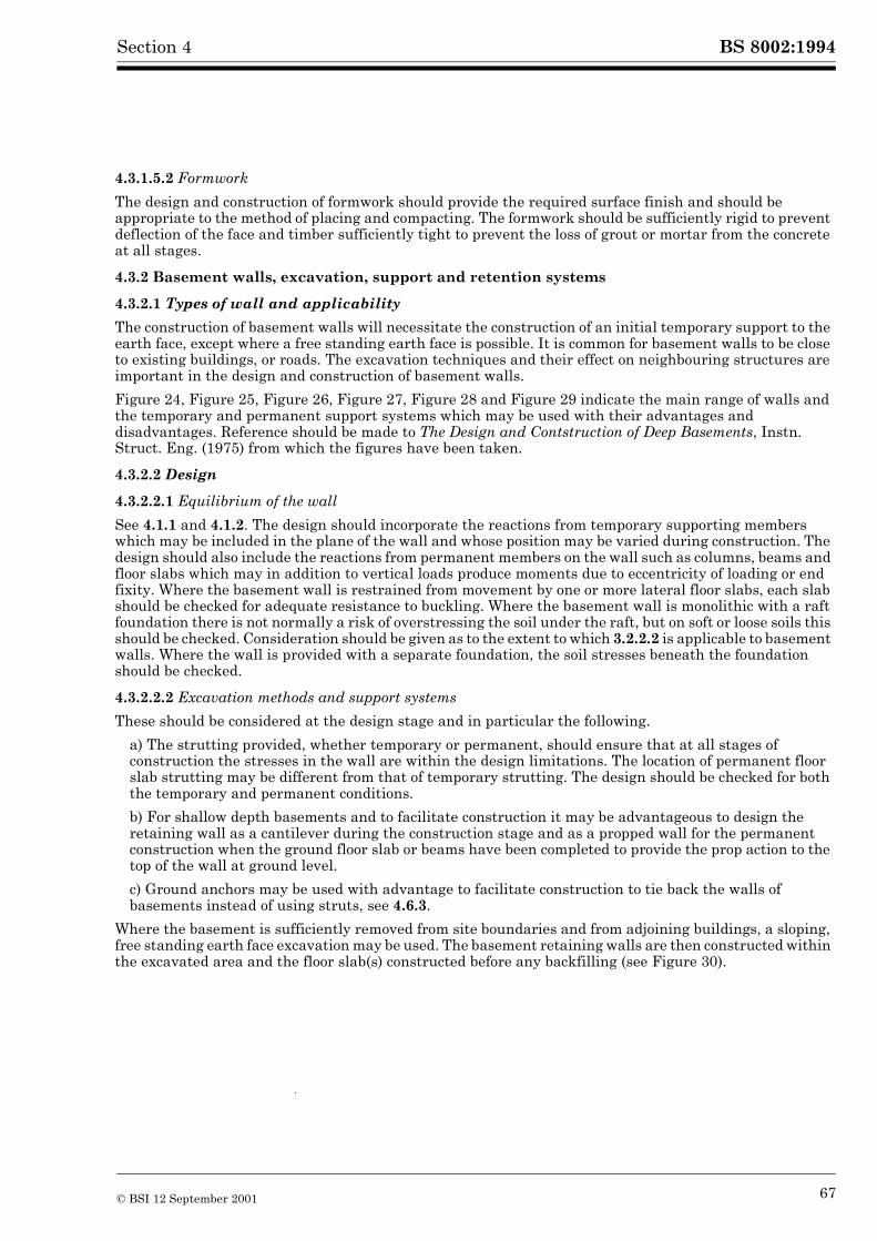
BS 8002:1994Section 4
4.3.1.5.2 Formwork
The design and construction of formwork should provide the required surface finish and should be appropriate to the method of placing and compacting. The formwork should be sufficiently rigid to prevent deflection of the face and timber sufficiently tight to prevent the loss of grout or mortar from the concrete at all stages.
4.3.2 Basement walls, excavation, support and retention systems
4.3.2.1 Types of wall and applicability
The construction of basement walls will necessitate the construction of an initial temporary support to the earth face, except where a free standing earth face is possible. It is common for basement walls to be close to existing buildings, or roads. The excavation techniques and their effect on neighbouring structures are important in the design and construction of basement walls.
Figure 24, Figure 25, Figure 26, Figure 27, Figure 28 and Figure 29 indicate the main range of walls and the temporary and permanent support systems which may be used with their advantages and disadvantages. Reference should be made to The Design and Contstruction of Deep Basements, Instn. Struct. Eng. (1975) from which the figures have been taken.
4.3.2.2 Design
4.3.2.2.1 Equilibrium of the wall
See 4.1.1 and 4.1.2. The design should incorporate the reactions from temporary supporting members which may be included in the plane of the wall and whose position may be varied during construction. The design should also include the reactions from permanent members on the wall such as columns, beams and floor slabs which may in addition to vertical loads produce moments due to eccentricity of loading or end fixity. Where the basement wall is restrained from movement by one or more lateral floor slabs, each slab should be checked for adequate resistance to buckling. Where the basement wall is monolithic with a raft foundation there is not normally a risk of overstressing the soil under the raft, but on soft or loose soils this should be checked. Consideration should be given as to the extent to which 3.2.2.2 is applicable to basement walls. Where the wall is provided with a separate foundation, the soil stresses beneath the foundation should be checked.
4.3.2.2.2 Excavation methods and support systems
These should be considered at the design stage and in particular the following.
a) The strutting provided, whether temporary or permanent, should ensure that at all stages of construction the stresses in the wall are within the design limitations. The location of permanent floor slab strutting may be different from that of temporary strutting. The design should be checked for both the temporary and permanent conditions.
b) For shallow depth basements and to facilitate construction it may be advantageous to design the retaining wall as a cantilever during the construction stage and as a propped wall for the permanent construction when the ground floor slab or beams have been completed to provide the prop action to the top of the wall at ground level.
c) Ground anchors may be used with advantage to facilitate construction to tie back the walls of basements instead of using struts, see 4.6.3.
Where the basement is sufficiently removed from site boundaries and from adjoining buildings, a sloping, free standing earth face excavation may be used. The basement retaining walls are then constructed within the excavated area and the floor slab(s) constructed before any backfilling (see Figure 30).
© BSI 12 September 2001 67
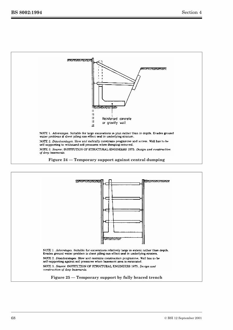
BS 8002:1994 Section 4
Figure 24 — Temporary support against central dumping
Figure 25 — Temporary support by fully braced trench
68 © BSI 12 September 2001
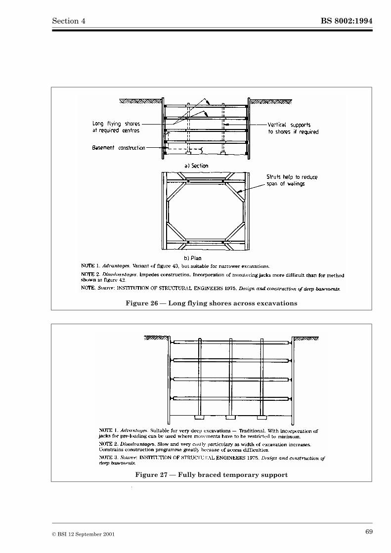
BS 8002:1994Section 4
Figure 26 — Long flying shores across excavations
Figure 27 — Fully braced temporary support
© BSI 12 September 2001 69
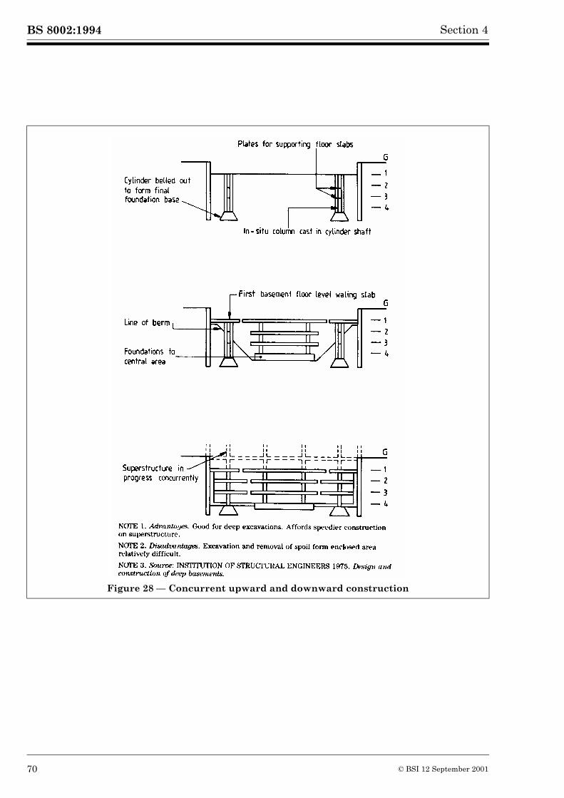
BS 8002:1994 Section 4
Figure 28 — Concurrent upward and downward construction
70 © BSI 12 September 2001
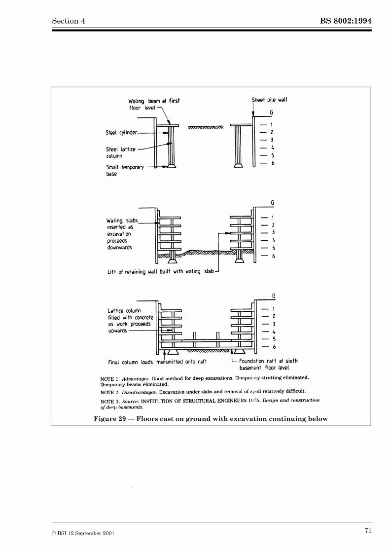
BS 8002:1994Section 4
Figure 29 — Floors cast on ground with excavation continuing below
© BSI 12 September 2001 71
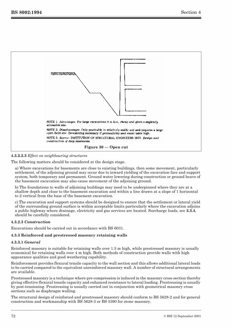
BS 8002:1994 Section 4
4.3.2.2.3 Effect on neighbouring structures
The following matters should be considered at the design stage.
a) Where excavations for basements are close to existing buildings, then some movement, particularly settlement, of the adjoining ground may occur due to inward yielding of the excavation face and support system, both temporary and permanent. Ground water lowering during construction or ground heave of the basement excavation may also cause movement of the adjoining ground.
b) The foundations to walls of adjoining buildings may need to be underpinned where they are at a shallow depth and close to the basement excavation and within a line drawn at a slope of 1 horizontal to 2 vertical from the base of the basement excavation.
c) The excavation and support systems should be designed to ensure that the settlement or lateral yield of the surrounding ground surface is within acceptable limits particularly where the excavation adjoins a public highway where drainage, electricity and gas services are located. Surcharge loads, see 3.3.4, should be carefully considered.
4.3.2.3 Construction
Excavations should be carried out in accordance with BS 6031.
4.3.3 Reinforced and prestressed masonry retaining walls
4.3.3.1 General
Reinforced masonry is suitable for retaining walls over 1.5 m high, while prestressed masonry is usually economical for retaining walls over 4 m high. Both methods of construction provide walls with high appearance qualities and good weathering capability.
Reinforcement provides flexural tensile capacity to the wall section and this allows additional lateral loads to be carried compared to the equivalent unreinforced masonry wall. A number of structural arrangements are available.
Prestressed masonry is a technique where pre-compression is induced in the masonry cross section thereby giving effective flexural tensile capacity and enhanced resistance to lateral loading. Prestressing is usually by post-tensioning. Prestressing is usually carried out in conjunction with geometrical masonry cross sections such as diaphragm walling.
The structural design of reinforced and prestressed masonry should conform to BS 5628-2 and for general construction and workmanship with BS 5628-3 or BS 5390 for stone masonry.
Figure 30 — Open cut
72 © BSI 12 September 2001
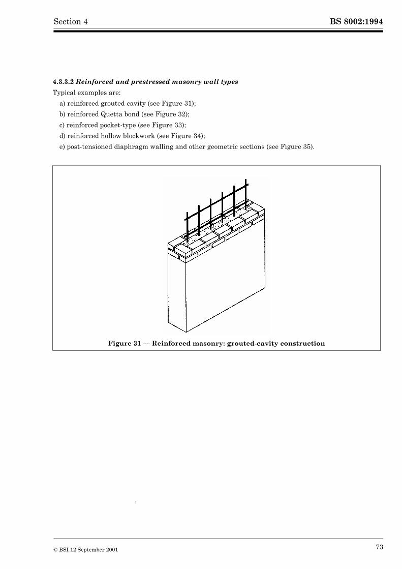
BS 8002:1994Section 4
4.3.3.2 Reinforced and prestressed masonry wall types
Typical examples are:
a) reinforced grouted-cavity (see Figure 31);
b) reinforced Quetta bond (see Figure 32);
c) reinforced pocket-type (see Figure 33);
d) reinforced hollow blockwork (see Figure 34);
e) post-tensioned diaphragm walling and other geometric sections (see Figure 35).
Figure 31 — Reinforced masonry: grouted-cavity construction
© BSI 12 September 2001 73
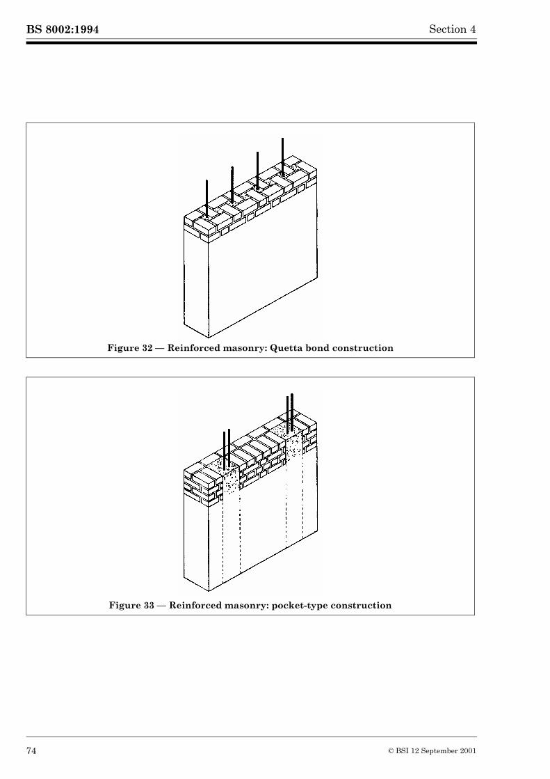
BS 8002:1994 Section 4
Figure 32 — Reinforced masonry: Quetta bond construction
Figure 33 — Reinforced masonry: pocket-type construction
74 © BSI 12 September 2001
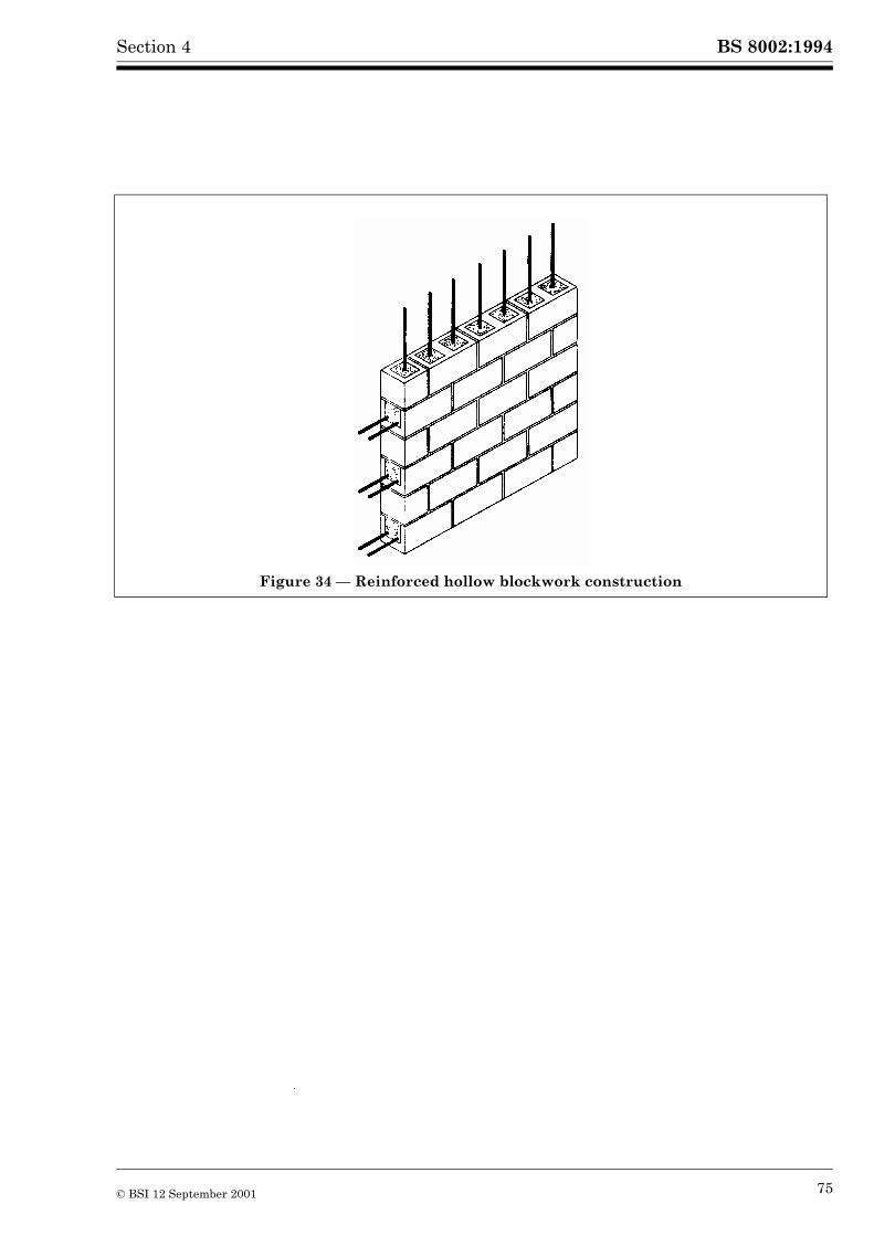
BS 8002:1994Section 4
Figure 34 — Reinforced hollow blockwork construction
© BSI 12 September 2001 75
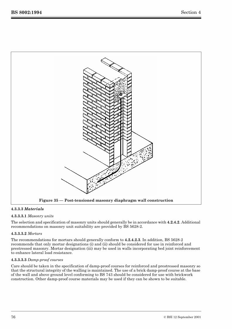
BS 8002:1994 Section 4
4.3.3.3 Materials
4.3.3.3.1 Masonry units
The selection and specification of masonry units should generally be in accordance with 4.2.4.2. Additional recommendations on masonry unit suitability are provided by BS 5628-2.
4.3.3.3.2 Mortars
The recommendations for mortars should generally conform to 4.2.4.2.3. In addition, BS 5628-2 recommends that only mortar designations (i) and (ii) should be considered for use in reinforced and prestressed masonry. Mortar designation (iii) may be used in walls incorporating bed joint reinforcement to enhance lateral load resistance.
4.3.3.3.3 Damp-proof courses
Care should be taken in the specification of damp-proof courses for reinforced and prestressed masonry so that the structural integrity of the walling is maintained. The use of a brick damp-proof course at the base of the wall and above ground level conforming to BS 743 should be considered for use with brickwork construction. Other damp-proof course materials may be used if they can be shown to be suitable.
Figure 35 — Post-tensioned masonry diaphragm wall construction
76 © BSI 12 September 2001
BS 8002:1994Section 4
4.3.3.3.4 Concrete infill and grout
These should be in accordance with BS 5628-2. In some applications mortar can be used as infill around reinforcement in reinforced masonry depending upon the type of steel used and the exposure situation.
4.3.3.3.5 Reinforcing and prestressing steel
These should be selected and specified in accordance with BS 5628-2.
4.3.3.3.6 Wall ties
Where wall ties are required, for example in reinforced grouted-cavity wall construction, these should be specified and provided in accordance with BS 5628-2.
4.3.3.4 Design
4.3.3.4.1 Equilibrium of the wall
See 4.1.1 and 4.1.2.
4.3.3.4.2 Structural design
The structural design of walls should be in accordance with BS 5628-2.
4.3.3.4.3 Movement joints
Movement joints should be incorporated in reinforced and prestressed masonry earth retaining structures in accordance with the guidance given in BS 5628-3. The location of movement joints in relation to reinforcement and prestressing wires or bars should be given careful consideration in the wall design and layout.
4.3.3.5 Construction
4.3.3.5.1 General
The construction of, and workmanship for, masonry used in reinforced and prestressed masonry retaining walls should be in accordance with BS 5628-3 or BS 5390 as appropriate. Additional guidance specific to reinforced and prestressed masonry is given in BS 5628-2.
Protective detailing to walling may be required depending upon the type of masonry units selected for the wall construction and should be provided in accordance with the recommendations of 4.2.4.2.1 and 4.2.4.2.2.
4.3.3.5.2 Concrete infilling and grouting
Where cavities or voids, containing reinforcement, are to be filled with concrete infill or grout, the reinforcement should be properly located and infilling should be carried out in accordance with the recommendations in BS 5628-2. There are two methods of infilling using either low-lift or high-lift techniques. With some types of reinforced masonry wall construction (e.g. grouted-cavity and Quetta bond construction) additional care is needed to maintain cavities and voids clear of debris and to position reinforcement correctly in order that efficient infilling can be achieved. If mechanical compaction of infilling is carried out this should avoid disruption of either the masonry or the reinforcement.
4.3.3.5.3 Reinforcement and wall ties
Main and secondary reinforcement, bed joint reinforcement and wall ties where used, should be correctly located and reinforcement should be wired-in where necessary. Where dissimilar steels are used in the same construction they should be positioned so as not to be in direct contact.
4.3.3.5.4 Waterproofing
The recommendations in 4.2.4.4.2 for unreinforced masonry walls apply to reinforced and prestressed masonry retaining walls.
© BSI 12 September 2001 77
BS 8002:1994 Section 4
4.4 Embedded walls
4.4.1 General
Embedded or sheet walls are built of contiguous or interlocking individual piles or diaphragm wall-panels to form a continuous structure capable of retaining soil and to some extent, water. Piles may be of timber, concrete or steel and may have lapped, V-shaped, tongued and grooved or interlocking joints between adjacent piles. Diaphragm wall-panels are formed of reinforced concrete.
Embedded retaining walls may be cantilever, anchored or propped structures, see Figure 36. Cantilever walls derive their equilibrium from the lower, embedded depth of the wall; anchored or propped walls derive their equilibrium partly from the lower embedded depth of the wall and partly from an anchorage or prop system which supports the upper part of the wall.
Special considerations, in respect of displacement and movement, apply to walls with multi-level supports.
4.4.2 Types of wall and applicability
Cantilever retaining walls are suitable for only moderate height. It is usual to limit the maximum height of such sheet pile cantilever walls to 5 m, but even this may be excessive where soft or loose soils occur in front of the wall. Stiffer cantilever walls, of concrete or steel including diaphragm walls and heavy composite walls, may be satisfactory to heights of 12 m providing the ground is strong enough to give adequate support. The deflections at the head of a cantilever wall are significant. It is preferable not to use cantilever walls when services or foundations are located wholly or partly within the active zone since horizontal and vertical movement in the retained material may cause damage.
Anchored or propped walls may have one or more levels of anchor or prop in the upper part of the wall. They can be designed to have fixed or free earth support at the bottom; they derive their stability mainly from the anchorages or props. They are common in cofferdams with several levels of supporting frames, see 4.5.
For anchored or propped walls in the free earth condition, the penetration of the piles should be designed so that the passive pressure in front of the piles will resist the forward movement of the toes of the piles, but will not prevent rotation. The piles are supported by ties at the top of the wall and the soil at the base of the wall, in a manner similar to a vertical beam with simple supports. In the fixed earth condition further penetration of the piles is required to ensure not only that the passive pressures at the front of the wall resist forward movement but that the rotation of the toe is restrained by the development of passive pressures near the toe at the rear of the wall. The provision of a simple support at the top due to the anchor or ties and a fixed support due to the soil at the base of the wall is similar to a vertical propped cantilever.
4.4.3 Design
4.4.3.1 General
The design procedure recommended is based on the calculation of the design earth pressures as described in 3.1.9. Traditional methods of design for embedded walls have been widely used, but these methods all have recognized shortcomings. These methods are outlined in Annex B and comments are included on the applicability of each method.
4.4.3.2 Equilibrium of the wall
See 4.1.1 and 4.1.2.
The general procedure is first to determine the depth of penetration to ensure overall equilibrium of the wall and the soil and secondly to determine the structural design of the wall to resist the imposed loadings.
Where the retaining wall is supported by a multi-stage support system, the loads on the supported system of struts or anchors may be derived from the trapezoidal distribution of active pressure shown in Figure 37. This method should be used within the limits given in Terzaghi and Peck (1967, p 396 et seq). In addition to the loads due to earth pressures in granular materials water pressure and pressures due to surcharge loads should be added. In granular materials Ka is determined from the graphs in Annex A. In clay soils the calculations are based upon the undrained shear strength of the clay soil with Ka = 1 – (4cu/�H) for soft to medium clay. The diagram for stiff fissured clays is tentative; the lower pressures are relevant only when movement can be kept to a minimum and construction time is short. The Terzaghi and Peck (revised) (1967) method should not be used to calculate the associated pile bending moments. The moments can be derived satisfactorily as shown in Figure 38. For walls with two levels of anchorages, a design method based on assuming an equivalent anchor (B. J. Jack, 1971) has generally produced conservative designs.
78 © BSI 12 September 2001
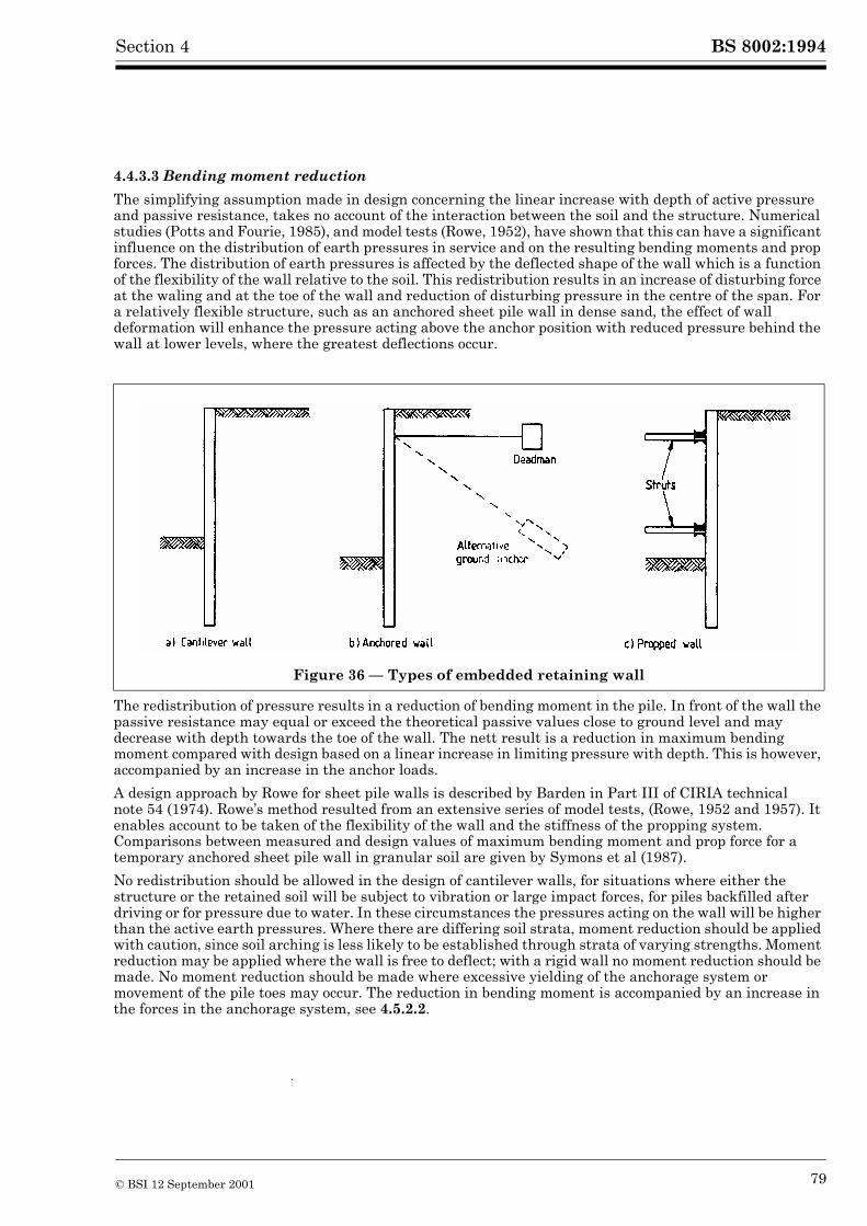
BS 8002:1994Section 4
4.4.3.3 Bending moment reduction
The simplifying assumption made in design concerning the linear increase with depth of active pressure and passive resistance, takes no account of the interaction between the soil and the structure. Numerical studies (Potts and Fourie, 1985), and model tests (Rowe, 1952), have shown that this can have a significant influence on the distribution of earth pressures in service and on the resulting bending moments and prop forces. The distribution of earth pressures is affected by the deflected shape of the wall which is a function of the flexibility of the wall relative to the soil. This redistribution results in an increase of disturbing force at the waling and at the toe of the wall and reduction of disturbing pressure in the centre of the span. For a relatively flexible structure, such as an anchored sheet pile wall in dense sand, the effect of wall deformation will enhance the pressure acting above the anchor position with reduced pressure behind the wall at lower levels, where the greatest deflections occur.
The redistribution of pressure results in a reduction of bending moment in the pile. In front of the wall the passive resistance may equal or exceed the theoretical passive values close to ground level and may decrease with depth towards the toe of the wall. The nett result is a reduction in maximum bending moment compared with design based on a linear increase in limiting pressure with depth. This is however, accompanied by an increase in the anchor loads.
A design approach by Rowe for sheet pile walls is described by Barden in Part III of CIRIA technical note 54 (1974). Rowe’s method resulted from an extensive series of model tests, (Rowe, 1952 and 1957). It enables account to be taken of the flexibility of the wall and the stiffness of the propping system. Comparisons between measured and design values of maximum bending moment and prop force for a temporary anchored sheet pile wall in granular soil are given by Symons et al (1987).
No redistribution should be allowed in the design of cantilever walls, for situations where either the structure or the retained soil will be subject to vibration or large impact forces, for piles backfilled after driving or for pressure due to water. In these circumstances the pressures acting on the wall will be higher than the active earth pressures. Where there are differing soil strata, moment reduction should be applied with caution, since soil arching is less likely to be established through strata of varying strengths. Moment reduction may be applied where the wall is free to deflect; with a rigid wall no moment reduction should be made. No moment reduction should be made where excessive yielding of the anchorage system or movement of the pile toes may occur. The reduction in bending moment is accompanied by an increase in the forces in the anchorage system, see 4.5.2.2.
Figure 36 — Types of embedded retaining wall
© BSI 12 September 2001 79
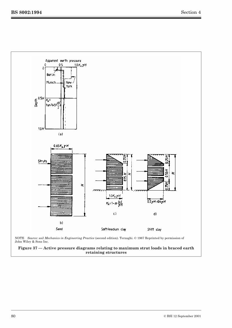
BS 8002:1994 Section 4
NOTE Source: soil Mechanics in Engineering Practice (second edition). Terzaghi. © 1967 Reprinted by permission of John Wiley & Sons Inc.
Figure 37 — Active pressure diagrams relating to maximum strut loads in braced earth retaining structures
80 © BSI 12 September 2001
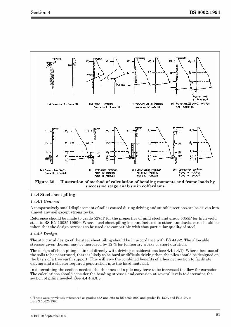
BS 8002:1994Section 4
4.4.4 Steel sheet piling
4.4.4.1 General
A comparatively small displacement of soil is caused during driving and suitable sections can be driven into almost any soil except strong rocks.
Reference should be made to grade 5275P for the properties of mild steel and grade 5355P for high yield steel to BS EN 10025:19904). Where steel sheet piling is manufactured to other standards, care should be taken that the design stresses to be used are compatible with that particular quality of steel.
4.4.4.2 Design
The structural design of the steel sheet piling should be in accordance with BS 449-2. The allowable stresses given therein may be increased by 12 % for temporary works of short duration.
The design of sheet piling is linked directly with driving considerations (see 4.4.4.4.1). Where, because of the soils to be penetrated, there is likely to be hard or difficult driving then the piles should be designed on the basis of a free earth support. This will give the combined benefits of a heavier section to facilitate driving and a shorter required penetration into the hard material.
In determining the section needed, the thickness of a pile may have to be increased to allow for corrosion. The calculations should consider the bending stresses and corrosion at several levels to determine the section of piling needed. See 4.4.4.4.3.5.
Figure 38 — Illustration of method of calculation of bending moments and frame loads by successive stage analysis in cofferdams
4) These were previously referenced as grades 43A and 50A to BS 4360:1990 and grades Fe 430A and Fe 510A to BS EN 10025:1990.
© BSI 12 September 2001 81
BS 8002:1994 Section 4
4.4.4.3 Section modulus of steel sheet piling
Sections of “Z” type steel sheet piling, which have their interlocks in the flanges, develop the full section modulus of an undivided wall of piling under all conditions. Sections of trough type steel sheet piling with close-fitting interlocks along the centre line or neutral axis of the sheeting develop the strength of the combined section only when the piling is fully driven into the ground. Loads on the supporting system may be derived from the distribution of active pressure as shown in Figure 37 based upon the Terzaghi and Peck (revised) (1967) method. The shear forces in the interlocks may be considered as resisted by friction due to the pressure at the walings and the restraint exercised by the ground. In certain conditions it is advisable to connect together the inner and outer piles in each pair by welding, pressing or other means, to ensure that the interlock common to the pair can develop the necessary shear resistance. Such conditions arise when:
a) the piling passes through soft clay or water;
b) the piling is prevented by rock from penetrating to the normal depth of cut-off;
c) the piling is used as a cantilever;
d) the piling is supported by props or struts but is cantilevered to a substantial distance above the highest waling or below the lowest waling.
If any of these conditions arise and the pairs of piles are not connected together as described, a reduced value of the section modulus of the combined section should be used in accordance with the manufacturer’s recommendations.
4.4.4.4 Construction
4.4.4.4.1 Driving sheet piles
The stresses which will be imposed on the piles during driving should be considered when the sheet pile wall is being designed. Pile sections require sufficient driving strength, otherwise they may suffer damage during installation, or it may be impossible to drive the piles to the required depth and expensive delays may result.
Sheet piles may be installed by impact, vibratory or hydraulic drivers and driving stresses will vary, dependent on the type of drive used. Impact methods generate the highest stresses during installation, but have the advantage of being suitable for all soil types. Vibratory and hydraulic pressing systems do not impose high peak stresses in the piles during installation, but are not fully effective in certain types of soil. Unless the soil conditions are consistent, some driving with impact hammers may be needed. Panel driving of a series of sheet piles interconnected to form a panel, is advisable as it ensures the maximum control of line and verticality and reduces driving resistance to a minimum. Further guidance on driving practice is given in BS 8004. A lighter section of sheet pile may be acceptable for structural purposes for soils with high values of internal friction or cohesion as they apply smaller active pressures to the wall than weaker soils. However stronger soils generate more resistance to driving and consequently, a pile which is suitable for structural requirements may be incapable of withstanding the driving forces. The criteria for adequacy of the pile section are that the pile head should not be damaged by the hammer impact, the pile shaft should sustain the driving force without buckling and the pile toe should not be damaged by the soil resistance. Driving forces vary with the driving method, but Table 5, which is based on unadjusted blow count values N obtained in the standard penetration test, may be used as a guide in the absence of more detailed knowledge.
This guide is based on experience with piles of British manufacture and of approximately 500 mm width, driven with impact hammers and using the panel driving method of installation. Sections of greater width, or those driven by other methods, may require somewhat heavier sections than those indicated in the table. Table 5 is based on the fact that in granular soils the major part of the resistance to penetration results from point resistance at the toe of the pile. Shaft friction with the surrounding soil contributes relatively little to the overall resistance to pile penetration. The required section is, therefore, related to the density of the soils being penetrated by the pile toe at all stages of the drive, the length of embedded shaft having only a small influence.
82 © BSI 12 September 2001
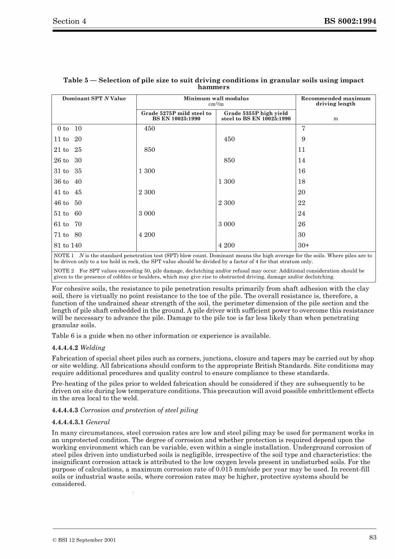
BS 8002:1994Section 4
Table 5 — Selection of pile size to suit driving conditions in granular soils using impact hammers
For cohesive soils, the resistance to pile penetration results primarily from shaft adhesion with the clay soil, there is virtually no point resistance to the toe of the pile. The overall resistance is, therefore, a function of the undrained shear strength of the soil, the perimeter dimension of the pile section and the length of pile shaft embedded in the ground. A pile driver with sufficient power to overcome this resistance will be necessary to advance the pile. Damage to the pile toe is far less likely than when penetrating granular soils.
Table 6 is a guide when no other information or experience is available.
4.4.4.4.2 Welding
Fabrication of special sheet piles such as corners, junctions, closure and tapers may be carried out by shop or site welding. All fabrications should conform to the appropriate British Standards. Site conditions may require additional procedures and quality control to ensure compliance to these standards.
Pre-heating of the piles prior to welded fabrication should be considered if they are subsequently to be driven on site during low temperature conditions. This precaution will avoid possible embrittlement effects in the area local to the weld.
4.4.4.4.3 Corrosion and protection of steel piling
4.4.4.4.3.1 General
In many circumstances, steel corrosion rates are low and steel piling may be used for permanent works in an unprotected condition. The degree of corrosion and whether protection is required depend upon the working environment which can be variable, even within a single installation. Underground corrosion of steel piles driven into undisturbed soils is negligible, irrespective of the soil type and characteristics: the insignificant corrosion attack is attributed to the low oxygen levels present in undisturbed soils. For the purpose of calculations, a maximum corrosion rate of 0.015 mm/side per year may be used. In recent-fill soils or industrial waste soils, where corrosion rates may be higher, protective systems should be considered.
Dominant SPT N Value Minimum wall moduluscm3/m
Recommended maximum driving length
Grade 5275P mild steel to BS EN 10025:1990
Grade 5355P high yield steel to BS EN 10025:1990 m
0 to 10 450 7
11 to 20 450 9
21 to 25 850 11
26 to 30 850 14
31 to 35 1 300 16
36 to 40 1 300 18
41 to 45 2 300 20
46 to 50 2 300 22
51 to 60 3 000 24
61 to 70 3 000 26
71 to 80 4 200 30
81 to 140 4 200 30+NOTE 1 N is the standard penetration test (SPT) blow count. Dominant means the high average for the soils. Where piles are to be driven only to a toe hold in rock, the SPT value should be divided by a factor of 4 for that stratum only.
NOTE 2 For SPT values exceeding 50, pile damage, declutching and/or refusal may occur. Additional consideration should be given to the presence of cobbles or boulders, which may give rise to obstructed driving, damage and/or declutching.
© BSI 12 September 2001 83
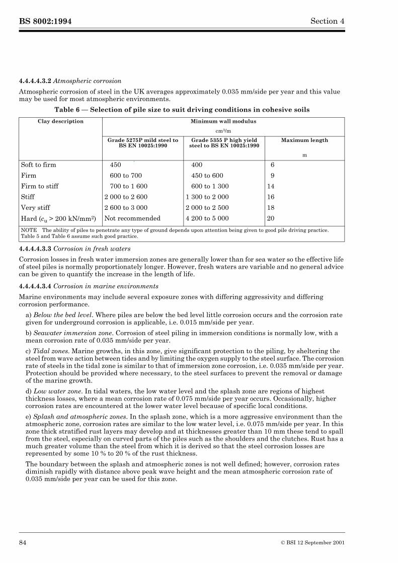
BS 8002:1994 Section 4
4.4.4.4.3.2 Atmospheric corrosion
Atmospheric corrosion of steel in the UK averages approximately 0.035 mm/side per year and this value may be used for most atmospheric environments.
Table 6 — Selection of pile size to suit driving conditions in cohesive soils
4.4.4.4.3.3 Corrosion in fresh waters
Corrosion losses in fresh water immersion zones are generally lower than for sea water so the effective life of steel piles is normally proportionately longer. However, fresh waters are variable and no general advice can be given to quantify the increase in the length of life.
4.4.4.4.3.4 Corrosion in marine environments
Marine environments may include several exposure zones with differing aggressivity and differing corrosion performance.
a) Below the bed level. Where piles are below the bed level little corrosion occurs and the corrosion rate given for underground corrosion is applicable, i.e. 0.015 mm/side per year.
b) Seawater immersion zone. Corrosion of steel piling in immersion conditions is normally low, with a mean corrosion rate of 0.035 mm/side per year.
c) Tidal zones. Marine growths, in this zone, give significant protection to the piling, by sheltering the steel from wave action between tides and by limiting the oxygen supply to the steel surface. The corrosion rate of steels in the tidal zone is similar to that of immersion zone corrosion, i.e. 0.035 mm/side per year. Protection should be provided where necessary, to the steel surfaces to prevent the removal or damage of the marine growth.
d) Low water zone. In tidal waters, the low water level and the splash zone are regions of highest thickness losses, where a mean corrosion rate of 0.075 mm/side per year occurs. Occasionally, higher corrosion rates are encountered at the lower water level because of specific local conditions.
e) Splash and atmospheric zones. In the splash zone, which is a more aggressive environment than the atmospheric zone, corrosion rates are similar to the low water level, i.e. 0.075 mm/side per year. In this zone thick stratified rust layers may develop and at thicknesses greater than 10 mm these tend to spall from the steel, especially on curved parts of the piles such as the shoulders and the clutches. Rust has a much greater volume than the steel from which it is derived so that the steel corrosion losses are represented by some 10 % to 20 % of the rust thickness.
The boundary between the splash and atmospheric zones is not well defined; however, corrosion rates diminish rapidly with distance above peak wave height and the mean atmospheric corrosion rate of 0.035 mm/side per year can be used for this zone.
Clay description Minimum wall modulus
cm3/m
Grade 5275P mild steel to BS EN 10025:1990
Grade 5355 P high yield steel to BS EN 10025:1990
Maximum length
m
Soft to firm 450 400 6
Firm 600 to 700 450 to 600 9
Firm to stiff 700 to 1 600 600 to 1 300 14
Stiff 2 000 to 2 600 1 300 to 2 000 16
Very stiff 2 600 to 3 000 2 000 to 2 500 18
Hard (cu > 200 kN/mm2) Not recommended 4 200 to 5 000 20
NOTE The ability of piles to penetrate any type of ground depends upon attention being given to good pile driving practice.Table 5 and Table 6 assume such good practice.
84 © BSI 12 September 2001
BS 8002:1994Section 4
4.4.4.4.3.5 Methods of increasing effective life
The effective life of unpainted or otherwise unprotected steel piling, depends upon the combined effects of imposed stresses and corrosion. Where measures for increasing the effective life of a structure are necessary, the following should be considered.
a) Use of a heavier section. Effective life may be increased by the use of additional steel thickness as a corrosion allowance. Maximum corrosion seldom occurs at the same position as the maximum bending moment: accordingly, the use of a corrosion allowance is a cost effective method of increasing effective life.
b) Use of a high yield steel. An alternative to using mild steel in a heavier section is to use a higher yield steel and retain the same section. Although both types of steel have similar corrosion rates, the use of grade Fe 510A steel to BS EN 10025:1990 at BS EN 10025:1990 Grade Fe 430A stresses will allow an additional 30 % loss of permissible thickness to be sustained without detriment. This method in effect, builds in a corrosion allowance and gives an increase of 30 % in effective life of a steel piling structure for an increase of about 9 % in steel costs.
c) Organic coatings. Steel piles should normally be coated under shop conditions. Paints should be applied to the cleaned surface by airless spraying and then cured rapidly to produce the required coating thickness in as few coats as possible.
d) Concrete encasement. Concrete encasement may be used to protect steel piles in marine environments. The use of concrete may be restricted to the splash zone by extending the concrete cope to below the mean high water level; both splash and tidal zones may be protected by extending the cope to below the lowest low water level. The concrete itself should be of a quality sufficient to resist seawater attack. See 4.3.1.4.7.
e) Cathodic protection. The design and application of cathodic protection systems to marine piled structures is a complex operation requiring the experience of specialist firms. Cathodic protection is considered to be fully effective only up to the half-tide mark. For zones above this level, including the splash zone, alternative methods of protection may be required, in addition to cathodic protection. Where cathodic protection is used on maritime structures, provision should be made for earthing ships and buried services to the quay.
4.4.5 Timber sheet piles
4.4.5.1 General
Timber sheet piling may be used for walls of moderate height, in river and sea defence works and in wharf construction. The timber should be resistant to attack by wood destroying organisms either by virtue of its natural durability or by treatment with wood preservatives. Timber sheet piling may be an economic material but the joints are not as watertight as steel sheet piling.
4.4.5.2 Materials
4.4.5.2.1 Types of timber
Certain softwoods and hardwoods are suitable as permanent sheet piling. The choice will depend upon availability in suitable sizes, appropriate preservation treatment, the expected service life and the relative cost.
In the United Kingdom, Douglas fir is the most common softwood used for sheet piles and is imported in sections up to 350 mm square and 12 m long. Pitch pine is also used and is imported in sections up to 400 mm square and 10 m long. Greenheart has been the most commonly used hardwood for permanent works and is normally imported rough hewn in sections up to 450 mm square and up to 15 m long. Other hardwoods such as balau, chengal, ekki, basralocus, kapur, keruing, okan, opepe, purpleheart and jarrah may also be used. Sections should be ordered sufficiently long to ensure that after cut off at the proper level the top is left clean and sound.
4.4.5.2.2 Dimensions
The cross-sectional shape of the sheet pile should be such that adjacent piles fit into one another; the joints should be tongued and grooved, chamfer-tongued, or of similar form, see Figure 39, to ensure the correct alignment of the sheeting during driving and to minimize seepage of soil and water through the wall after completion.
© BSI 12 September 2001 85
BS 8002:1994 Section 4
4.4.5.2.3 Quality of timber
The timber piles should be free from defects which may affect their strength and durability. Straightness of grain is important particularly where hard driving is anticipated. Some of the defect limitations used in arriving at stress grades in BS 5268-2 are irrelevant and suitable material may generally be obtained from standard grade for hardwoods and SS grade for softwoods. The centre line of a sawn pile should not deviate from the straight by more than 25 mm throughout its length. All timber piles should be inspected before driving to ensure compliance with these requirements.
4.4.5.3 Design
Working stresses should not exceed the green permissible stresses given in BS 5268-2 for the species and grade of timber being used. In calculating the stresses account should be taken of the stresses during installation and in use. Allowance should be made for reduction in section by drilling or notching.
4.4.5.4 Construction
4.4.5.4.1 Pile heads
Before driving, precautions should be taken to prevent “brooming”, by trimming the head of the pile at right angles to the length and fitting a steel band around the top. Alternatively expanded metal caps can be used, which, after the first blow, become embedded in the timber. After driving, the heads of piles should be cut off square to sound wood and treated with preservative before capping.
4.4.5.4.2 Pile shoes
Driving should be carried out with the tongue leading and with each sheet bevelled on the tongue side so that the pile is forced against the previous pile. The driving edge may be shaped as shown in Figure 40. In hard driving conditions the edge should be provided with a shoe of thin steel plate.
4.4.5.4.3 Durability
The durability of timber used in the construction of timber sheet piles should conform to the recommendations given in Section 4 of BS 5589:1989.
86 © BSI 12 September 2001
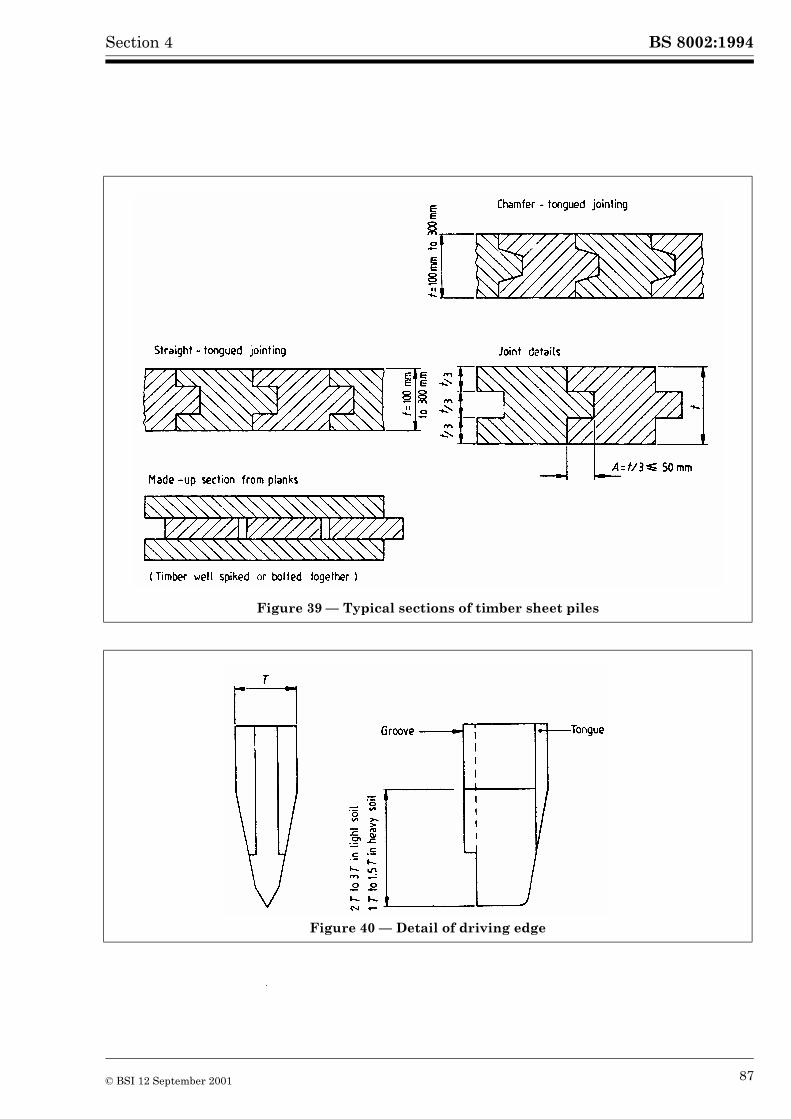
BS 8002:1994Section 4
Figure 39 — Typical sections of timber sheet piles
Figure 40 — Detail of driving edge
© BSI 12 September 2001 87

BS 8002:1994 Section 4
4.4.6 Reinforced and prestressed concrete sheet piles
4.4.6.1 General
Where concrete sheet piles can be installed to achieve the required ground penetration they merit consideration; jetting or preboring can be used in suitable ground to assist the driving. Good durability and appearance can be obtained, particularly with prestressed concrete and precast production methods.
The general requirements for materials, design details and the manufacture and driving of reinforced and prestressed concrete piles given in 7.4.2 and 7.4.3 of BS 8004:1986 are equally applicable to reinforced and prestressed concrete sheet piles.
4.4.6.2 Reinforced concrete sheet piles
The following recommendations apply to reinforced concrete sheet piles.
a) General. The design, manufacture and handling should be in accordance with 7.4.2 of BS 8004:1986.
b) Concrete. For the various conditions of driving and exposure the concrete mix and strengths should be in accordance with Table 12 of BS 8004:1986.
c) Reinforcement. The reinforcement should conform to BS 8110-1 or BS 5400-4, BS 5400-7 and BS 5400-8 for resisting the applied forces. The lateral reinforcement is important in resisting the driving stresses. The cover requirements in BS 8110-1 should be the minimum requirements.
d) Dimensions. The dimensions depend on design, the thickness should generally be in the range of 120 mm to 400 mm. The normal width of a concrete pile is 500 mm but the width at the head is reduced to suit standard driving caps. The toe of the pile is generally wedge shaped to assist close driving.
e) Joints. Sheet piles are provided with tongued and grooved joints either trapezoidal, triangular or semicircular in shape. These assist in correct alignment of the sheeting during driving and also minimize the seepage of soil through the wall after completion. Watertightness may be achieved through specially designed interlocks or through grouted joints.
f) Driving. The recommendations in 7.4.2.5 of BS 8004:1986 should be followed in driving concrete sheet piles.
4.4.6.3 Prestressed concrete sheet piles
The main advantages are:
a) high strength in bending and ability to withstand tensile stresses during driving and to take hard driving;
b) relatively crack-free in handling, pitching and driving;
c) economical design for given loads and moments;
d) greater durability in different environments.
The requirements for materials, manufacture and driving of prestressed concrete piles should be as set out in BS 8110-1 or BS 5400-4, BS 5400-7 and BS 5400-8 and 7.4.3 of BS 8004:1986.
In the design tensions up to a maximum of 50 % of the modulus of rupture (in tension) may be permitted provided the ultimate strength requirements are satisfied. In this respect the guidance for class 2 structures in 4.3.4.3 of BS 8110-1:1986 is appropriate.
4.4.7 In situ concrete pile walls
4.4.7.1 General
Bored piles are used when a soil replacement rather than a soil displacement method of piling is required to form a retaining wall and when there is a requirement to minimize vibration. They may be unsuitable where the ground water level on the retained side of the wall is high. Their best application is in cohesive soils. For the construction of bored piles reference should be made to BS 8004.
An advantage of a bored pile retaining wall is that only one pile need be bored at a time. Hence, when working close to an existing foundation, only a short length of the foundation need be exposed to any risk of ground loss or movement at a given time. It may also be easier to overcome ground obstructions than with sheet piling or diaphragm wall construction. In addition, bored piling systems have a capacity to penetrate moderately hard bedrock materials more easily than alternative methods.
88 © BSI 12 September 2001

BS 8002:1994Section 4
4.4.7.2 Types of wall and applicability
The following recommendations apply to two types of pile wall.
a) Close bored or contiguous pile walls. These walls are built with piles at centres which are equal to or slightly greater than the external diameter of the casing or lining. Borehole casing is required to retain granular and similar unstable soils during boring near the ground surface or throughout its length, depending on the ground conditions. This type of wall is unsuitable for retaining water-bearing granular soils which are liable to bleed through the gaps between the piles, unless special measures are taken to provide a seal between adjacent piles.
b) Secant pile walls. Secant piles are bored at centres less than the diameter of the casing. Alternate piles are thus of full circular section, while intervening piles are cut away in part during the construction process. A fully continuous relatively watertight retaining wall may be constructed provided the tolerances of positioning and verticality are sufficient to eliminate gaps between piles.
4.4.7.3 Materials
Concrete and reinforcement should conform to the requirements of BS 8004, BS 8110-1 or BS 5400-4, BS 5400-7 and BS 5400-8. The mix should be designed to provide the necessary structural strength and the flow requirements to ensure adequate compaction and continuity. Special methods of placement, for example by tremie should be taken into account. See Sliwinski Z. and Fleming W.G.K. (1974). Reinforcement cages should be built to withstand the lifting and handling stresses. These may be relatively high. Welding of reinforcement, where used, should use techniques which maintain the full strength of the steel.
4.4.7.4 Design
Where props or anchorages are used to support the wall at various levels, waling beams should be provided along the face of the wall at these lateral support levels to unify behaviour. The waling beams may be designed as horizontally spanning steel or concrete beams; where steel beams are used, a satisfactory method of wedging or infilling should be provided to take up the gaps between individual piles and the waling beam. The gaps occur as a result of surface irregularities or deviations from true verticality and position of individual piles. A continuous structural beam should be cast along the heads of the piles to unify their behaviour both as an earth retaining wall and in order to distribute any vertical load which may also be applied.
Ties, such as ground anchors, are normally passed between piles in close bored pile wall construction.
4.4.7.5 Construction
4.4.7.5.1 Tolerances
The normal tolerances which can be expected in the formation of close bored pile walls are approximately 1 in 75 to 1 in 100 for verticality and 50 mm for lateral plan tolerances measured at right angles to the line of the wall.
The lateral tolerance may be improved by forming a guide wall in the ground on either side of the pile positions. This is not a usual practice and may be costly. Timber or concrete sleepers may be used to improve accuracy at relatively low cost.
The required verticality tolerance for secant piles is normally of the order of 1:200 and for positional tolerances of the order of 25 mm. Where walls have to be constructed in close proximity to other structures the clearances required are dependent on the particular piling equipment to be used.
© BSI 12 September 2001 89

BS 8002:1994 Section 4
4.4.7.5.2 Finishes
Bored pile walls may require treatment in order to provide a suitable finished surface. All surface finishes should take account of the potential variations in the profile of the wall face. Close bored pile walls may be designed to incorporate vertical drains between piles, so as to produce a suitable water collecting drainage system in front of the finished wall. These may be accommodated at the time when finishes are applied.
Surface treatment to bored pile walls may consist of:
a) structural concrete; or
b) gunite; or
c) precast concrete panels; or
d) brick facing.
Where structural concrete or gunite is used with close bored pile walls, the soil should be cut back between the piles and the concrete surfaces should be cleaned, so as to provide a reasonably good structural key before erecting shuttering and casting the finishing concrete.
A wall finish which prevents subsequent damp penetration can be obtained using structural concrete provided the minimum finish depth is adequate. It is, however, more difficult to obtain a waterproof wall with gunite. Both types of applied concrete are normally reinforced with steel mesh.
Where a precast concrete cladding is used, adequate fixings should be provided, either from the capping beam or by casting nibs on the piles to support the precast units. Where nibs are cast on, suitable bars should be incorporated within the pile at the required levels. These bars are subsequently exposed by breaking out; they are then bent and bonded into the nibs.
Where either precast concrete or brick facings are used the soil between the piles should be cut back and where necessary the gaps between the piles should be filled with gunite or trowelled on cement mortar to prevent the soil from falling and accumulating behind the cladding. Independent brick facing may need to be provided with a separate foundation and behind-the-wall drainage.
4.4.8 Diaphragm walls
4.4.8.1 General
Diaphragm walls are cast or placed in the ground using a bentonite or polymer suspension, as part of the construction process. Excavation is carried out in the suspension to a width equal to the thickness of wall required. The excavation equipment uses either rope suspended grabs, grabs mounted on Kelly bars, or reverse-circulation excavating equipment. The bentonite suspension is designed to maintain the stability of the slit trench during digging and until the diaphragm wall has been concreted (Instn. Civ. Engrs., Diaphragm Wall Conference 1975).
Walls are formed in panels of predetermined length. The length is controlled by the type of equipment and the economics of construction, adjacent surcharges, the types of soil being excavated, the size and weight of reinforcement cage that can be handled, the total quantity of concrete that can be placed in one panel and the positions of anchorages or struts and walings. Reinforcement is not commonly linked from one panel into another, but in some systems special joints have been devised, which transfer forces between adjacent panels. The concrete cast in situ is placed by tremie; it is essential that the concrete flows freely without segregation so as to surround completely the reinforcement and displace the bentonite.
4.4.8.2 Materials
See 4.4.7.3 for recommendations.
90 © BSI 12 September 2001

BS 8002:1994Section 4
4.4.8.3 Construction
4.4.8.3.1 General
The following recommendations apply in the construction of diaphragm walls.
a) Guide walls. Reinforced concrete guide walls are first built to define the line and thickness of the wall and to ensure a positive head against any ground water pressure. The walls should be reinforced continuously; they are usually cast in the dry on and against firm ground or alternatively, if necessary, the outer face of the guide walls may be supported by a backfill of lean mix concrete.
b) Bentonite. Bentonite, which consists mainly of minerals of the montmorillonite group, should be suitable for civil engineering purposes. There are two forms of bentonite, sodium bentonite and calcium bentonite; each has markedly different properties. Sodium bentonite is usually used, either that naturally occurring or obtained by the chemical treatment of calcium bentonite.
During excavation, the bentonite suspension becomes contaminated with solids from the soil. This may lead to the build up of thick filtercake at a faster rate than is desirable on the walls of the excavation and may cause difficulty in displacing the bentonite suspension by the tremied concrete. Accordingly the density, viscosity, shear strength and pH value of the bentonite suspension should be checked at various stages in the work and any unsatisfactory levels of contamination should be corrected before proceeding with the rest of the construction (Fleming W.G.K. et al 1975).
c) Construction joints. A normal joint is formed by inserting a round stop end pipe at the end of the excavation. This is withdrawn when the concrete has set, so forming a semi-circular joint against which the concrete of the next panel is placed.
d) Watertightness. Sound workmanship should be used in concreting and in the construction of joints so as to achieve a reasonable watertightness. Movement at joints may occur during or subsequent to the removal of earth from one side of the wall because of varying plan configurations, with stiffer panel sections at corners or because of different depths of excavation. To avoid differential movement and the associated leakages uniformity of stiffness is desirable, but is impractical to achieve. Accordingly provision should be made for the sealing of joints by grouting or other techniques subsequent to construction (Sliwinski Z. and Fleming W.G.K., 1974).
e) Use of panels to support vertically and horizontally applied loads. Diaphragm walls may support additional vertical and horizontal loads. If vertical loads are to be carried by end bearing of the bases attention should be given to ensuring a clean panel base to ensure end bearing contributes significantly to the total bearing capacity.
Load transfer to the soil by friction between the wall and soil may also be used but for this to be fully mobilized panels should be concreted without any long delay following the completion of excavation.
f) Deep circular excavations. Deep circular excavations may be retained by a series of panels in contact forming a circular plan retaining wall. Where the circumferential thrust is to be taken by the ring of panels directly and not by waling beams, the tolerances of verticality and the physical integrity are particularly important.
4.4.8.3.2 Prestressed cost in situ walls
Cast-in-place diaphragm walls may be prestressed using post-tensioning techniques; the cables should be looped so that both ends are accessible at the top of the wall. A suitable reinforcement cage should be made for the attachment of the cable ducts so as to provide the cable profile best suited to the design. The fixings should be sufficiently stable and robust to withstand the stresses due to handling and the forces due to rising concrete during concreting.
Reference should be made to BS 8110-1 or BS 5400-4 for the general recommendations of post-tensioned prestressed concrete design and construction.
4.4.8.3.3 Precast concrete walls
A precast concrete diaphragm wall is formed of precast units placed in a bentonite filled trench, excavated by normal methods. Part of the bentonite suspension is first displaced by a cement/bentonite grout tremied into the base of the excavation. Precast wall panels with suitable arranged jointing and locating systems are then lowered to the required depth in the trench. The quantity of cement bentonite grout should be such that when all the precast panels, corresponding to the trench length excavated, have been fixed, they are fully immersed in the grout mixture.
© BSI 12 September 2001 91

BS 8002:1994 Section 4
The cement bentonite grout is not required to develop high strengths and needs to be only marginally stronger in its final state than the ground in which the wall is embedded and upon which it relies for support. The stage of displacement of bentonite suspension by grout may be avoided by carrying out all the trench excavation using a cement bentonite grout suspension, instead of conventional bentonite.
Several proprietary types of precast walling system are available; they differ as regards the joints between panels and the way in which the wall is fixed in position in the ground by the cement grout. Some are reinforced conventionally, while others are of prestressed concrete.
Precast diaphragm wall panels should conform to the recommendations of BS 8110-1 except in so far as the design is modified in this document. Since one of the purposes of using precast walling is to provide a satisfactory finished appearance for the wall subsequent to excavation, care and accuracy are important throughout fabrication and installation.
4.4.9 Soldier/king piles
4.4.9.1 General
These consist of vertical members built at suitable centres with a system of ground support spanning between them. The piles are first installed along the perimeter of the proposed excavation. Sheeting, supporting the ground, is placed in position as excavation proceeds. The sheeting spans either horizontally between the soldier/king piles or vertically between horizontal walings, see Figure 41 and Figure 42. Sheet piles interlocking with H-section piles are also commonly used.
Soldier/king piles may be used to support deep, narrow, shallow or wide excavations in various materials including clays and sands. Excavation in water-bearing ground may require special attention; this method is unsuitable for the exclusion of water and if soil is washed out from behind the sheeting unacceptable settlement may be caused to adjacent structures or services.
Support to the piles may be by walings and struts, raking shores, tie rods and anchorages or ground anchorages. The piles should be designed to span vertically between the supports provided. The design of the piles should accommodate any resulting vertical forces from inclined anchors or supports.
Figure 41 — Horizontal sheeting (lagging)
Figure 42 — Vertical sheeting (lagging)
92 © BSI 12 September 2001

BS 8002:1994Section 4
4.4.9.2 Materials
The following materials are recommended for piles and sheetings.
a) Piles. The piles may be of reinforced concrete or steel sections used either singly or in pairs. Where steel sections are used in pairs adequate batten plates or spacers should be provided to ensure the composite action of both piles. See Figure 43.
b) Sheeting (lagging). Steel and concrete may be used for sheeting, but the most common material is timber. This is easily handled and cut on site to suit variations in site conditions. Structural softwoods to BS 5268-2 are suitable.
Steel trenching may be used as sheeting; it is relatively light and can be trimmed to the correct length if necessary. Concrete may be used, either as prestressed precast planks or in situ concrete. Precast planks are heavy to handle, difficult to cut to length and exhibit brittle failure without visible or audible warning.
4.4.9.3 Design
The earth pressure to be resisted depends on the stiffness of the support system. The design should cater for all stages of excavation and support installation as well as for the final excavated condition.
Where anchorages are provided to support the piles then the piles and the walings should be able to redistribute 40 % of the load to adjacent anchorages so as to accommodate the situation where an individual anchorage fails to carry its full design load. Adequate penetration of the piles below formation level should be provided to permit the mobilization of sufficient passive resistance for both normal conditions and also to allow for the risk of over excavation as well as to prevent instability in the bottom of the excavation.
Where timber sheeting is used a 50 % reduction may be assumed in the design of the sheeting members in the loading from the soil, due to the arching action of the soil. The relieving effect of the arching is much reduced with use of stiffer sheeting materials, for example concrete, due to the lower relative flexibility of the concrete sheeting.
4.4.9.4 Construction
As excavation proceeds, exposing the soldier/king piles, the spaces between adjacent piles are closed with horizontal sheeting. In clay soils it is common practice to uncover the face to a depth of 1 m between piles before the sheeting is placed, but in loose waterlogged ground the sheeting should be placed as soon as possible to prevent a cave-in. Various methods of locating the sheeting (lagging) are shown in Figure 44.
Gaps of 50 mm may be left between the lagging to facilitate drainage of ground water, so reducing the load on the soldier piles and supports. In loose ground the 50 mm gaps should be packed with straw to prevent a loss of ground between the louvres, whilst still allowing water to percolate. Voids behind the sheeting should be packed as construction proceeds to prevent movement of the supported ground towards the excavation. The sheeting should be firmly wedged or fixed to the soldier piles as construction proceeds.
Figure 43 — Composite steel soldier piles
© BSI 12 September 2001 93

BS 8002:1994 Section 4
Figure 44 — Various methods of locating the sheeting (lagging)
94 © BSI 12 September 2001

BS 8002:1994Section 4
4.5 Strutted excavations and cofferdams
4.5.1 General
4.5.1.1 Single skin cofferdams and strutted excavations
These may be formed with piles supported either by a framework within the cofferdam, or by external anchorages around the perimeter. Cantilever pile cofferdams may also be formed and are designed in the same way as cantilever retaining walls.
When the cofferdam is very large in area, but of relatively shallow depth, consideration should be given to incorporating external anchorages or to using raking struts from the foundations of the permanent structure, in order to achieve economy.
4.5.1.2 Cofferdams for river crossings
This type of cofferdam is used when a pipeline is to be laid across a river and it is impracticable to close the waterway. See Figure 45.
4.5.1.3 Earth-filled double-wall and cellular cofferdams
Earth-filled cofferdams are self-supporting gravity structures, either parallel-sided double-wall cofferdams or cellular cofferdams. The stability of both types is dependent on the properties of the filling and of the soil at foundation level, as well as on the arrangement and type of the steel sheet piling. Typical uses are as dams to seal off temporarily dock entrances so that work below water level can be carried out in the dry and in the construction of permanent walls for land reclamation, quays, wharves and dolphins.
Double-wall cofferdams consist of two parallel lines of steel piling connected together by a system of steel walings and tie rods and sometimes struts at one or more levels. The space between the lines of piling is filled with coarse cohesionless material such as sand, gravel or broken rock.
© BSI 12 September 2001 95

BS 8002:1994 Section 4
4.5.1.4 Design
4.5.1.4.1 Piling
In strutted excavations, the design of the piling should be checked, not only in the final excavated condition with all frames in position, but also during every stage of both excavation and construction of the supporting framing, as well as the subsequent removal of the frames.
In addition to the design surcharge loading given in 3.3.4 the effect of isolated heavy plant or equipment imposing large point or line loads should be taken into account.
The piles may be assumed to be simply supported at the frames and at the excavation level (in both temporary and final conditions) they will have either “fixed” or “free” earth support in the embedded length depending upon the type of soil and the depth of cut-off of the piles.
The most suitable method of calculating bending moments in walls and the load in the various supporting frames, whether anchored or propped is by successive analysis of each stage of construction as shown in Figure 38. This will determine the bending moments and loadings occurring during the temporary conditions, which develop as the excavation is carried out, prior to the installation of each frame. These moments and loads are normally larger than those calculated for the structure in the completed condition.
The most economic section of sheet piling will be the lightest section capable of being driven to the depth determined in the design calculations and which can resist the design bending moments calculated in the cofferdam design. A heavier section and/or a higher quality of steel may be required where long piles are to be driven to deep penetrations or where hard driving is to be encountered, also see 4.4.4.4.1.
Figure 45 — Cofferdam for river crossing
96 © BSI 12 September 2001

BS 8002:1994Section 4
4.5.1.4.2 Equilibrium of the strutted excavation or cofferdam
See 4.1.1 and 4.1.2.
In strutted excavations, where soil is supported, the soil pressure diagram in the final stage of excavation relating to the strut loads is parabolic but may be approximated to a trapezoidal shape as shown in Figure 37. These diagrams do not include the effect of water pressure; they provide an envelope of strut loading which will cover the maximum loads in the struts of the framing system. The diagrams should not be used to calculate the bending moment in the piling during both of the temporary stages of construction, i.e. excavation and removal. This method may also be applied to retaining walls with multiple levels of tie-backs, but only when the wall is formed by excavation or dredging in front of the wall. It should not be used for a backfilled type wall. Alternatively the pressure and strut loads may be obtained by using a stage by stage method of analysis (James and Jack, 1975).
4.5.1.4.3 Cofferdams in water
See Figure 46. Where a cofferdam is to be built in still water the spacing of the walings can be taken from standard handbooks. If frames are installed “in the dry” with the water in the cofferdam lowered in stages, then the tables in standard handbooks may not apply and a stage by stage analysis should be carried out.
4.5.1.4.4 Cofferdams with unbalanced loading (dock wall and riverside construction)
This type of cofferdam is subjected to a heavier loading on the landward side than on the seaward side, due to the soil pressure, surcharges and additional head of water. The water pressure is generally higher on the landward side. Precautions, dependent on site conditions, should be taken to overcome the unbalanced loadings. Suitable alternative methods are:
a) removal of soil on the landward side, so as to reduce the soil pressures;
b) provision of a restricted area adjacent to the cofferdam, within which plant and vehicles are prohibited so as to reduce the surcharge;
c) placing spoil on the water side of the cofferdam to increase the passive resistance;
d) provision of an anchorage system on the landward side;
e) using raking struts inside the cofferdam.
Figure 46 — Cofferdam in water
© BSI 12 September 2001 97

BS 8002:1994 Section 4
4.5.1.4.5 Double-wall cofferdams
The inner line of piling should be designed as an anchored retaining wall, while the outer line of piling acts as the anchorage. The width of the dam should be not less than 0.8 of the retained height of water and/or soil.
The inner wall is usually provided with weep holes near the bottom to reduce water pressure and to prevent a decrease in the total shear strength of fill material. Complete drainage of the fill may be impossible and so allowance should be made for a hydrostatic head within the fill of at least 0.3 of the retained height.
The penetration of the piling into the soil below excavation or dredged level should be sufficient to develop the necessary passive resistance and prevent horizontal sliding and to control the effects of seepage.
This type of cofferdam is uneconomical if there is rock at excavation level unless the rock is such that steel piling can be driven into it to an adequate penetration. If the rock is hard it may be possible, at low water, to excavate a trench into which the piling may be concreted to obtain the necessary seal and horizontal resistance for the cofferdam. Where rock may be encountered grade 5355P or higher to BS EN 10025:1990 steel sheet piles should be used. These piles withstand harder driving, and also punch into the rock with less risk of buckling, than piles of grade 5275P steel to BS EN 10025:1990.
4.5.1.4.6 Arrangement of supporting frames
Framing within a cofferdam should be arranged to permit carrying out construction work within the cofferdam in a satisfactory manner. The spacing of members horizontally and vertically should be such as to permit the use of plant during excavation and the construction of a permanent structure within the cofferdam. Vertical spacing of the frames should be designed to ensure that the piles and the frames are not overstressed in any temporary condition during cofferdam excavation.
4.5.1.5 Construction
4.5.1.5.1 Minimum depth of cut-off in cohesionless soils
When a cofferdam is constructed in cohesionless soil, and the water level outside the cofferdam is appreciably higher than the excavation level, the length of the piles should be sufficient to prevent the soil in the bottom of the cofferdam becoming unstable due to the upward flow of water from under the toes of the piles. The upward flow of water into the bottom of the cofferdam may induce soil instability within the cofferdam and also a reduction of passive resistance. The sections of piling and the bottom frames should be checked. In marine cofferdams this risk of instability may be reduced by placing a less permeable blanket around the outside of the cofferdam, right up to the sheet piling, so as to increase the lengths of the seepage paths in a manner similar to the increased path length which results if the cut-off is increased.
When water is pumped from a sump at excavation level, the sump should be situated as far as possible from the walls of the cofferdam. Any flow of water into the cofferdam may carry fines from the surrounding soil and cause subsidence or piping. Local instability may occur in conditions of piping as the passive resistance is destroyed.
The flow of water beneath the toes of the piles may be reduced where it is possible to lower the ground water level outside the cofferdam. A system of well-points or filter wells at pile toe-level can, as an alternative, control the flow of water into the cofferdam.
Where the flow of water into the cofferdam is likely to be excessive, excavation and positioning of frames should be carried out whilst the cofferdam remains flooded. A plug of concrete should then be placed by tremie at excavation level and the cofferdam pumped dry. This concrete plug should be either of sufficient weight to resist the uplift forces or should incorporate pipes to relieve the water pressure.
4.5.1.5.2 Prevention of heave
In soft cohesive soils there is a risk of the flow or heaving of the bottom of a deep cofferdam. Where a cofferdam is founded in cohesive soil which is underlain by water under artesian pressure, relief wells may be needed to relieve the artesian pressure.
4.5.1.5.3 Circular cofferdams
The piles should, where possible, be pitched and the whole circle completed before driving is commenced. The piles should be driven in stages as the hammer works its way several times around the circumference. A diaphragm wall can be used to form a circular cofferdam.
98 © BSI 12 September 2001

BS 8002:1994Section 4
Earth pressures should be calculated as for straight-sided cofferdams and piles should be supported by circular ring beams, instead of walings and struts. This leaves the central area of the excavation clear of obstruction.
Due to the deviations in practice from a true circle the ring beams are subjected to eccentric loading and a check should be made for buckling in the ring with the radial waling load W(in kN/m) determined from
where
4.5.1.5.4 Earth-filled cofferdams
Clays or silts should not be used as filling material and any soft soils of these types which may be enclosed within the sheet piling should be removed before placing filling.
Under tidal conditions the water level outside the cofferdam may be above or below that within the soil inside the cofferdam and the cofferdam should be designed for these variable loading conditions.
Weepholes, with graded filters if necessary, should be provided near the bottom of the exposed portion of the piles on the inner side. Drainage of the filling should be undertaken to reduce the pressure on the inner line of piling and to prevent a decrease in the total shear strength of the filling. If complete drainage of the filling is impossible, an allowance should be made for any water pressure acting on the piling.
The same conditions regarding pile penetration and water seepage apply to this type of cofferdam as with other types.
4.5.2 Struts, ties, walings and anchorages
4.5.2.1 General
4.5.2.1.1 Walings
The choice of timber or steel for cofferdam bracing is controlled by the external loadings upon the piles under the most severe conditions as well as the internal dimensions of the cofferdam. Good quality timber such as Douglas fir or pitch pine may be used for lighter loadings.
Heavier loadings require the use of steel members, i.e. universal beams suitably reinforced by web stiffeners where necessary to safeguard against web buckling and torsional rotation, particularly where walings are suspended on hangers. Recommended maximum stresses to be employed in the design of cofferdam walings should be based on the stresses given in BS 449-2.
Reinforced concrete walings may be used in permanent cofferdams and in temporary works where the cofferdam will be open for a long period of time. They are especially useful when constructing a curved wall or circular cofferdam. Reinforced concrete provides high stiffness and eliminates the risk of web crushing and buckling which may occur when steel walings are poorly designed or badly assembled.
Positive support methods should be used to locate the frames, using hangers or brackets. Where diagonal struts are used, or where walings act as struts to other walings thus imposing an axial load, the members should be designed to withstand the combined stresses due to the axial and bending loads.
4.5.2.1.2 Struts
As with walings, good quality timber may be used for lighter loadings but steel struts should be used for heavier loadings. Where loadings are “severe” steel box piles or tubular steel piles may be used as struts. The design should make allowance for the self weight stresses and for the consequent eccentricity due to deflection as well as for accidental construction loadings.
(34)
E = Young’s modulus of waling material in N/mm2;
I = Moment of inertia about “xx” axis in cm4;
R = Radius of cofferdam in metres.
W 1.5 EI
R 3 10 5�---------------------------=
© BSI 12 September 2001 99

BS 8002:1994 Section 4
4.5.2.2 Design
4.5.2.2.1 General
The loads to be carried by the struts, ties, walings and anchorages should generally be determined in accordance with Section 3 and 4.1.1 and 4.1.2. However, if stresses in the sheet piling have been modified by bending moment reduction, the calculated load in the struts or ties should be increased by 25 %. Walings and anchors should be designed to carry these strut or tie rod loads.
The design should also accommodate the possible failure of an individual strut tie rod or anchor. The wall and walings should be capable of redistributing the load from the failed tie rod or anchor. An increase may be made in the allowable stresses up to yield values for steel and 0.8 � ultimate values for concrete and timber.
4.5.2.2.2 Walings
The horizontal reaction from an anchored sheet wall is generally carried to the struts, ties or anchorages by walings; where walings are omitted the attendant risks should be carefully considered. The loads on the walings are obtained by considering the same conditions as those used to obtain the bending moments in the piles (see 4.4.3.2 and 4.4.3.3). The loading from the sheeting members onto the waling should be distributed evenly by means, for example, of timber wedges.
The walings should be designed as continuous beams making due allowance for the end spans. The total system is statically indeterminate (or hyperstatic); an exact analysis would consider the elasticity of the tie rods, the rigidity of the waling and the stresses induced during bolting operations. In practice it is usual to adopt a simplified approach using an assumed bending moment wL2/10 where w is the uniformly distributed loading and L is the span length. Where walings are placed behind the pile they should be connected to the sheet piling by bolts with adequate bearing plates and washer plates; the steelwork should be of generous proportions to allow for corrosion and the stresses introduced when aligning the piling and to avoid the risk of web buckling; stiffeners should be provided as required.
Where the anchorages are inclined the vertical load component will be carried by walings. To ensure an adequate distribution of the vertical loads the clutches should be welded at the heads of the piles.
When diagonal tie rods are used to support end returns of the sheet piling, the design should cater for the horizontal components in the plane of both the wall and the return.
4.5.2.2.3 Steel walings
Steel walings should be designed in accordance with BS 449-2. They commonly consist of two spaced structural steel channels placed horizontally with their webs back to back. The channels are spaced a sufficient distance apart to allow the tie rods to pass between the web and be installed with ease, taking account of any inclination of the tie rods. Bolted or welded channel spacers are used to maintain the required spacing when the channels are connected. When the tie rods are horizontal, channel spacers at approximately 2.0 m to 2.5 m centres are generally adequate, but when walings are used in conjunction with inclined tie rods, it is advisable to reduce this spacing.
To ensure the continuity of steel walings, the joints should be located opposite the troughs of the piling adjacent to the tie rods at approximately one fifth of the span. The joints in upper and lower channels should be staggered and placed one on either side of the tie rod. If the joints cannot be spaced at the desired points, the walings should be designed to resist both the bending moment and the shear at the points where they occur. Web stiffeners may be necessary at anchor head points to resist web buckling due to the reaction of the tie rods. All permanent steelwork should be given protective treatment in accordance with BS 5493.
The minimum size of bolts for waling splice connections should be M20 and the minimum size of bolts for attaching walings to sheet piles should be M30. Bolts for waling splice connections should conform to BS 4190. Bolts for attaching walings to sheet piles should conform to BS 4190 or be designed as short tie rods (see 4.5.2.2.6).
4.5.2.2.4 Timber walings
Timber walings should be designed in accordance with BS 5268-2. Steel spreaders of sufficient area and stiffness should be provided at the tie rods to avoid over-stressing the walings. The walings should be connected to the sheet piling by bolts with adequate washers or bearing plates. The waling joints in tied walls should be located at approximately one fifth of the span and should be sufficiently strong to ensure continuity and to take shear forces from anchor head loads.
100 © BSI 12 September 2001

BS 8002:1994Section 4
In permanent works the steel bolts and plates used in walings should be galvanized in accordance with BS 729 or sheradized to BS 4921. All timberwork should be given protective treatment in accordance with BS 5589.
4.5.2.2.5 In situ and precast concrete walings
Concrete walings should be designed in accordance with BS 8110-1. The minimum characteristic compressive strength of the concrete at 28 days should be 25 N/mm2. Where walings are in contact with soil, sea water or fresh water aggressive to concrete then the minimum strength at 28 days should be 30 N/mm2.
A concrete capping beam is usually constructed on top of a permanent sheet pile wall. Where this capping beam is used as a waling it should be sufficiently strong to transmit vertical and horizontal loads from anchor ties into sheet piling unless other provisions such as welding at clutches are made. The waling should be designed as a beam, supported on elastic supports provided by sheet piling both in horizontal and vertical directions. Sufficient reinforcement should be provided in the capping beam to cope with shear forces arising from anchor head loads and also with shrinkage and temperature stresses.
4.5.2.2.6 Tie rods
Where tie rods are employed they may be critical to the stability of sheet piled walls. The design should provide for the increase in stresses which may arise from corrosion and also through the bending of tie rods due to the ground around them settling. For protection against corrosion buried permanent tie rods should be given a suitable sheathing, wrapping or coating, sufficiently flexible to accommodate the extension of the tie rods under load. Provision should be made in addition for corrosion at a rate of not less than 0.05 mm/year and if the ties are placed in aggressive ground or sea water, a greater wastage for corrosion should be provided. Whilst cathodic protection reduces corrosion some corrosion should be assumed in the design. Where cathodic protection is used to protect the tie rods all of the steel components of the wall should be similarly protected.
The tie rods should be provided with washers and bearing plates to give adequate bearing on the walings and on the concrete anchor blocks, if used. Tie rods having lengths over 12 m should be joined by couplers or turnbuckles. The rod diameter at the root of the threads of nuts and turnbuckles should be adequate to take the design tie load. Upset ends or rolled threads may be used to provide for the threads.
Tie rods should be designed in accordance with BS 449-2 using grade Fe 430 or grade Fe 510 steel to BS EN 10025:1990 or similar hot rolled non-alloy steel grades.
If settlement of the soil below tie rods is likely to occur, then the ends of the tie rods should be designed to allow for the movement. Alternatively the tie rods may be enclosed in flexible plastic ducts.
4.5.3 Cellular cofferdams
4.5.3.1 General
Cellular cofferdams are self supporting structures, constructed using straight web steel sheet piles driven to form cells of various shapes (see Figure 47) and filled with sand, gravel or broken rock. They can be founded on rock, sand or stiff clay and utilized as either temporary or permanent structures to retain considerable heights of soil and/or water.
The stability of a cofferdam depends upon the tensile strength of the sheet piling (especially the clutches), the properties of the filling, the shape and size of the cells and the foundation materials. The outward pressure of the filling produces high circumferential tensile forces in the piling, which the straight web piles are designed to resist, unlike trough shaped piles sections which are unsuitable.
4.5.3.2 Materials
4.5.3.2.1 Pile section
The shape of the interlock is designed to take the high circumferential tensile forces and at the same time permit sufficient angular deviation between adjacent piles to enable cells of a practical diameter to be formed. Since straight web piles lack bending strength in the flat position, care should be taken in handling and storing the piles. The minimum ultimate interlock strength is given in the manufacturer’s literature.
© BSI 12 September 2001 101

BS 8002:1994 Section 4
4.5.3.2.2 Fill
The fill material should have a high crushing strength combined with a high angle of shearing resistance to provide the necessary shear strength within the fill together with a sliding resistance at the base. The fill should be free draining and be relatively incompressible, i.e. coarse granular soils. Well graded sand is preferable but where uniform sand is to be used, fine materials should be avoided. Well graded crushed rock and mixtures of sand and gravel are ideal. Backfill placed behind the cellular cells should be coarse sand, gravel or clean rubble.
The fill should have a permeability greater than approximately 10–4 m/s.
4.5.3.2.3 Cell shape
As shown in Figure 47 various geometrical shapes are possible, each of which have advantages and disadvantages.
4.5.3.3 Types of wall and applicationNOTE The following lists describe the advantages and disadvantages of various types of wall.
4.5.3.3.1 Circular diaphragm cells
a) Advantages.
1) Each cell is a self-supporting unit.
2) Each cell can be filled independently of adjacent cells.
3) Circular diaphragm cells can be constructed in rough and flowing water (maximum velocity about 1.3 m/s).
b) Disadvantages.
1) Resistance to large water pressures is restricted by interlock tension.
2) Interconnecting arcs increase stresses and deformations of the main cell.
3) Pitching, closing and driving of cells requires great care to avoid developing excessively high forces in the interlocks.
4.5.3.3.2 Diaphragm cells
a) Advantages.
1) Large water pressures can be resisted by increasing diaphragm width.
2) Interlock tensions are uniform and smaller than those of a circular cofferdam with identical radius and height.
b) Disadvantages.
1) Cells are not independently stable. It is therefore advisable to include a full circular cell at intervals.
2) Difference in fill and water level between adjacent cells should be controlled sufficiently to avoid displacement of the diaphragm.
3) Several templates required during construction.
4.5.3.3.3 Cloverleaf cells
a) Advantages.
1) Cells are independently stable.
2) Larger size cells can be built by this method.
b) Disadvantages.
1) More sheet piles are required than circular or diaphragm cofferdams.
2) Fill and water levels in adjacent compartments of one cell should be reasonably uniform.
102 © BSI 12 September 2001

BS 8002:1994Section 4
4.5.3.4 Design
The design methods used are essentially empirical and differ in some respects from each other. The following methods and references should be considered. The Terzaghi (1945) method and subsequent modifications to it by TVA (1957), U.S. Corps of Engineers (1958) and Dept. of the Navy (1971) together with Cummings (1960) and Brinch Hansen’s methods (1953), Ovesen N.K. (1962), Lacroix Esrig and Luscher (1976).
In all methods, the safety of the cofferdam is evaluated against failure by the following modes:
a) bursting of the cells due to failure of the sheet pile interlock in tension; Experience has shown that “at rest” pressures can occur;
b) sliding on the base;
c) excessive leaning or tilting of cells due to shear failure of the fill;
d) failure of the foundation material.
The forces on the cofferdam during its various stages of construction should be determined.
Initially, during the filling of the cells, especially if hydraulic filling is used, the level of the soil and water may be at least as high as the lowest part of the top of the cell skin. The water level will be lower outside than inside and this is particularly significant under tidal conditions at low water. Further information on the design of cellular sheet pile structures is given in BS 6349-2.
Figure 47 — Types of cellular cofferdams
© BSI 12 September 2001 103

BS 8002:1994 Section 4
4.5.3.5 Construction
4.5.3.5.1 Foundations
Rock provides a suitable base for cellular cofferdams and penetration of the piles is not essential for stability. If there are gaps between the toe of the piles and the rock then measures should be taken to restrict seepage of water and to prevent the loss of fill. With sand and gravel foundations, the piling should penetrate sufficiently to prevent seepage affecting stability. A berm should be provided on sands, inside the cofferdam and possibly outside, to prevent scour.
Stiff or hard clays provide suitable foundations. Soft clays or silts should be removed before the cells are filled.
4.5.3.5.2 Drainage
In order to provide stability of a cellular cofferdam the elevation of the phreatic line should be maintained as low as practicable and drainage holes should be provided as low as possible in the inner line of piles of the cofferdam, together with filters as necessary.
4.5.3.5.3 Dewatering
When the unloaded side of the cofferdam is dewatered the rate of lowering the water level should not exceed the drainage capacity of the cells.
4.5.3.5.4 Performance
A cellular cofferdam is a flexible structure. Horizontal movements of the piles and vertical movements of the filling should be expected.
During filling of the cells barrelling of up to 150 mm is not unusual and additional deformation due to the pull from the adjacent cells is to be expected. Horizontal deflections at the top of high cofferdams can be significant and movements up to 500 mm are not unusual. Filling, especially on the unloaded side of a cofferdam, can settle and total settlement may be 150 mm or more.
4.6 Anchorages
4.6.1 General
An anchorage for an earth retaining structure is a system installed in the retained ground mass to provide a tensile form of support to the structure. Anchorage systems permit a clear excavation and they may be used as an alternative to struts.
When considering anchorages for retaining walls, the suitability of the proposed installation technique to ground conditions, the possible effect on adjoining buildings and the rights of adjoining owners under whose building or land the anchorages are to be inserted should be determined.
Anchorages for retaining walls are of three general types, ground anchorages including rock and soil anchorages, tension piles and deadman anchorages (see Figure 48). They may be used solely during construction, may form part of the permanent structure or may be designed to perform a dual function.
In order to produce a satisfactory design, anchorage loads should be evaluated together, where possible and practical, with an assessment of consequent deformations. The consequence of failure of any individual anchorage should be evaluated, together with an examination of the overall mass stability and/or effects of groups of anchorages, in accordance with the principles given in Section 3 regarding overall equilibrium.
4.6.2 Equilibrium
See 4.1.1 and 4.1.2.
4.6.3 Ground anchorages
4.6.3.1 General
The design and construction of ground anchorage systems and the material and components employed together with the necessary corrosion protection are dealt with in BS 8081 to which reference should be made. It is recommended that specialist work of this nature should be undertaken only by persons with the necessary geotechnical knowledge and experience.
104 © BSI 12 September 2001

BS 8002:1994Section 4
4.6.3.2 Design
Consideration should be given to the following.
a) It is usual for anchorages to be drilled inclined below the horizontal in order to reach more competent ground. Account should be taken of the effects on soil loadings, both behind and in front of the wall, due to the component forces arising from the inclination of the anchorage.
b) The overall safety factors should be determined by the life, nature and purpose of the anchorage.
c) Various proprietary computer programs are available to assist in the analysis of multi-anchored walls.
4.6.4 Tension piles
4.6.4.1 General
Tension piles, whether raked or vertical, are commonly used under relieving platforms to retaining walls and to form raked tension pile anchorages.
4.6.4.2 Design
Axial uplift forces on tension piles are resisted by skin friction on the pile shaft and any resistance offered by enlargement at the base or on the shaft of a pile (e.g. by under-reaming). Guidance on the evaluation of skin friction is given in 7.5 of BS 8004:1986, and Tomlinson M.J. (1987). However the most reliable guide to the capacity of a tension pile is given by an uplift load test. If this is neither desirable nor practical then the following matters should be taken into account when assessing the ultimate uplift capacity from calculations based on the properties of the soil or rock in which the pile is embedded.
a) Under conditions of cyclic loading or creep caused by sustained loading the uplift skin friction resistance of piles in cohesive soils and weak rocks can fall from a peak to a residual value, particularly for long piles.
b) Irreversible uplift movement of tension piles in cohesive soils subject to cyclic loading is unlikely to occur until the peak cyclic shear stress is 80 % of the ultimate state capacity.
c) The skin friction resistance to cyclic uplift loading of piles in cohesionless soils may be 30 % to 40 % lower than that given by static sustained loading, see Peuch A.A. (1982).
d) The ultimate skin friction of piles in cohesionless soils may be greatly reduced if pile installation or subsequent relative movement between the piles and soil causes degradation of the soil particles. This degradation may occur particularly with piles driven into calcareous soils, or where piles embedded in these soils are subjected to cyclic uplift loading.
e) The weight of the pile acts to reduce the total uplift load applied to the pile head.
f) Because of the reduction in skin friction from the peak to a lower residual value, tension failure in a pile may be sudden and catastrophic. Accordingly, the design should be based on a conservative assessment of the representative residual strength, taking account of the reduction below remoulded critical state strength of plastic clays (see 2.2.3) and the smoothness of the pile surface (see 2.2.8). The assessment of the design value of skin friction (see 3.2.6) should be based upon an upper limit of the representative residual strength. A conservative assessment should be made of the largest tensile load which may be applied by the pile (see 3.1.7).
The design of tension piles should also take account of any resistance afforded by an expansion of the base or shaft (e.g. under-reaming). Full length reinforcement will be required to ensure that the integrity of the pile is maintained under tensile loading.
4.6.5 Deadman anchorages
4.6.5.1 General
These usually consist of sheet pile or concrete anchor walls; they may be continuous or a series of separate units. Sheet pile anchorages are of the balanced or cantilever type. Whilst a concrete anchorage does not require the use of walings for the distribution of the load from the tie rod, it is necessary to excavate to the full depth of the anchorage. This may cause difficulties when the water table is near the ground surface. The anchors are connected by tendons to the earth retaining structure to form a complete anchored wall system.
The proportions and depth of embedment of the deadman are generally governed by the working load of the anchor and by the effective passive resistance available in front of the anchorage.
© BSI 12 September 2001 105

BS 8002:1994 Section 4
4.6.5.2 Design
4.6.5.2.1 General
See 4.1.1 and 4.1.2. Further general guidance on the design of deadman anchorages is given in BS 6349-2.
There are three basic design requirements to be satisfied by the anchorage.
a) The anchorage should not yield by moving forward a significant distance. The resistance to movement is related directly to the effective passive resistance of the soil and the friction between the anchorage and the soil.
b) The deadman should not undergo excessive settlement or rotation in relation to the tendons. This requirement is seldom significant in undisturbed granular soils but where the anchorage is located in uncompacted fill, or weak soils, it may be necessary to provide a foundation to the deadman or to use an alternative anchorage system. A certain amount of movement may be accommodated by the provision of pin-jointed tendons and tendon ducts.
c) The deadman unit should be designed to resist the bending moments and shear forces resulting from the tie bar forces and earth pressures acting upon it.
4.6.5.2.2 Overall equilibrium
Where the passive soil zone in front of the anchor wall does not interfere with the active soil zone behind the main retaining wall, see Figure 49, the design of each can be undertaken independently, see 4.1.1 and 4.1.2.
The average tension in the tie rods should be determined as sufficient to ensure equilibrium of the main retaining wall, under the required design situation. The specification of the design situations (see 3.2.2) should include the highest ground water level, the lowest external water level and the maximum live load which can reasonably be combined. The maximum live load will include, where appropriate mooring forces, repeat crane loadings and surcharge loads on the retained surface behind the main retaining wall.
Figure 48 — Types of anchorage
106 © BSI 12 September 2001

BS 8002:1994Section 4
In order to prevent progressive failure of a wall following the uncoupling or rupture of a single tie rod, the specification of the design situation should include the assumption that any tie rod may be defective and that the tension in the defective rod is shared between its nearest neighbours.
Where the active and passive zones of the main and anchor walls necessarily interfere, the anchor wall should be assumed not to develop full passive resistance due to lateral stress relief following active movement of the main wall. The anchor wall should be deepened to develop the required resistance. Consideration should be given to designing the combination of both walls, as a single unit similar to a mass wall, in which the effective resistance of the lower failure plane, see Figure 50, will then be invoked to preserve the overall equilibrium of the block. The internal equilibrium of the single unit should also be determined and in particular the moment equilibrium of the walls about their tie rod connections. Two levels of ties may be necessary.
4.6.5.2.3 Deadman design
The resistance to forward movement of the anchor wall is the difference between the passive resistance of the soil in front of the anchor wall, ignoring any surcharge or live load on this ground, and the active force on the back of the anchor wall including any surcharge or live load on this ground. The depth and length of the anchor wall should be sufficient to resist the total anchor force using the mobilized soil strengths (see 3.2.3 to 3.2.5). The factor of safety for anchorage system and individual members should not be less than 2 in accordance with BS 8081.
The existence or proposed construction of buried services and excavations will reduce passive resistance and a conservative level should be assumed for design. A group of individual deadman anchorages may be considered as a continuous anchorage where the spacing between individual anchorages does not exceed the depth to the top of the anchor.
Corrosion protection should be provided depending on the location of the anchorage (see BS 8081). At the end of the assumed life of the system the calculated factor of safety should be not less than 75 % of that originally assumed or 1.75 whichever is the greater.
Figure 49 — Non-interference of zones for anchored wall
© BSI 12 September 2001 107

BS 8002:1994 Section 4
4.7 Waterfront structures
4.7.1 General
The detailed design of waterfront structures is dealt with in BS 6349-1 to BS 6349-7 to which reference should be made.
4.7.2 Concrete and reinforcement
The durability of reinforced concrete in maritime conditions depends on the quality and impermeability of the concrete in preventing steel reinforcement from corroding. Cover to reinforcement in maritime structures should be preferably 75 mm but not less than 50 mm. This should be the minimum distance from the surface of any steel reinforcement links, tendons, or sheath to the surface of the concrete.
Sulfate ions, present in seawater at relatively high concentrations, react with tricalcium aluminate in hardened Portland cement. The rate of attack, which is greatest in warm or polluted waters, can be reduced by limiting the proportion of tricalcium aluminate in the cement and in UK waters a maximum of 10 % is recommended. The tricalcium aluminate content should not be less than 4 % in order to avoid attack of steel reinforcement by chlorides.
4.7.3 Design
4.7.3.1 Equilibrium of the walls
See 4.1.1 and 4.1.2.
4.7.3.2 Design level and overdredging
Where it is necessary to maintain, at all times, a minimum depth of water at the face of a waterfront structure, it is normal to identify a level above which all material may be removed. This level is arrived at by considering the loaded draught of the vessels using the berth, the underkeel clearance required and the tidal range. This level with a further obligatory allowance of 0.5 m is the design level.
Overdredging, that is, the removal of material below the design level, may be inevitable as a dredger will not be able to produce a given level without tolerance. Overdredging is sometimes used in order to achieve extended intervals between successive dredging campaigns.
Figure 50 — Double wall construction where zones interfere
108 © BSI 12 September 2001

BS 8002:1994Section 4
4.7.3.3 Hydraulic fill and backfilling generally
Where fill is deposited on the landward side of waterfront structures to form a level quay surface or a general area of reclamation, the fill may be placed before or after building the waterfront structure, depending on the type of structure and the method of construction.
Fill may be placed hydraulically, by pumping from dredgers or by depositing dry material from the shore, using earth moving equipment. Care should be exercised to ensure that during filling, stability is maintained at all stages of construction. Dry backfilling is generally placed by conventional tipping and the fill may be cohesive or noncohesive. It should be as free as practicable from organic matter and should be selected to ensure its suitability for its purpose as a filled area.
Where hydraulic fill is used, provision should be made for the drainage of water from the fill. The structure should be designed to support the standing hydraulic head and the resulting lateral pressure which will occur during hydraulic filling. The hydraulic fill level may be in excess of the final fill level. The resulting higher lateral pressure should be allowed for in the design. In addition there may occur excessive deflections in the structure; for this excess stress condition reduced factors of safety may be used.
Hydraulic fill should be granular and should be well graded so that it consolidates well and provides a dense and homogeneous fill behind the waterfront structure. Cohesive materials arising from a dredging operation are generally unsuitable. The consolidation period for such material requires a time measured in years.
Sand and gravel mixtures are normally suitable for use as hydraulic fill. Materials with a significant content of coarse grained material may cause pumping problems if there is a need to pump over long distances, due to the greater slurry velocity and hence greater energy input required.
If the hydraulic fill material contains a significant proportion of fines, problems may arise due to the natural tendency of the fines to segregate. Furthermore, in such material excess water may take some time to drain out.
There should be, at all times during the filling process, adequate anchorage capacity. This may require early filling immediately in front of and behind the anchorage. Undue settlement of filled material behind a waterfront structure is undesirable, particularly in future load bearing areas close to the waterfront structure. This may require the prior removal of soft and organic materials from the existing bed levels.
Backfill placed in the dry should be deposited in horizontal layers of thickness compatible with the nature of the material and the type of compaction equipment used to achieve the design density. Attention should be given to the compaction of the material immediately behind the structure; additional loading may be imposed by the compaction process. This should be evaluated with respect to the capacity of the structure to withstand such loading, see 3.3.3.6. Backfill material which is tipped through water should be granular and, as with hydraulic fill, due account should be taken of the variations in fill density which can occur.
4.7.3.4 Scour and its effects
A change in one of the parameters which define the sediment transport pattern may disturb the dynamic equilibrium of the system. In the context of waterfront structures scour may be caused by change in velocity or direction of the current. This, in turn, may be due to the construction of new works, the action of ships’ propellers, the removal or deposition of bed material or other action causing change in a steady current, turbulence or eddies. Silts, sands and gravels are susceptible to scour in diminishing order of sensitivity, while stiff cohesive soils are resistant and even comparatively soft clays may remain stable in conditions where a granular material might be eroded.
Scour may be reduced, or even prevented, if waterfront structures are designed so that the existing current or tidal regime is disturbed as little as possible. An ideal solution may be impossible, as patterns for ebb and flow may not be symmetrical and operational requirements may impose constraints. In such conditions, the best compromise should be sought.
Methods of measuring currents and sediment transport are given in Section 2 of BS 6349-1:1984.
Where the construction itself causes a change in current velocity for example at bridge piers, embankments, training works or reclamation works, an assessment should be made of the degree to which this may cause scour in the existing sea or river bed. If necessary the design of the works should provide for scour protection or for deepening of the bed which may result. Scour protection within the tidal zone is commonly achieved by some form of armouring and reference should be made to Sections 2 and 7 of BS 6349-1:1984, and Section 8 of BS 6349-5:1991. For protection in a submerged location it is usual to provide a natural or artificial rubble apron.
© BSI 12 September 2001 109

BS 8002:1994 Section 4
Where scour problems occur at an existing structure they may be removed by suitable training works, often quite simple in form. It is advisable that hydraulic model studies be undertaken to determine the most suitable form and to ensure that no detrimental effects are induced elsewhere. It is advisable to carry out routine hydrographic surveys at the face of waterfront structures if the bed is liable to erosion to ensure that the bed is not lowered to a point where the stability of the structure is jeopardized. The frequency of the surveys should be based on experience of the rate of bed erosion.
4.7.3.5 Tide and river levels
The design of waterfront structure in tidal waters should normally be based on highest and lowest astronomical tides. These are respectively the highest and lowest levels that can be predicted under average meteorological conditions and under any combination of astronomical conditions and are given in Admiralty tide tables.
Water levels may be raised above the predicted high tide levels by storm surges, by intense meteorological depressions causing seiches, by onshore winds and, in the case of estuaries by increased river flow arising from storm run-off. It is advisable to establish from data, if available, the probable frequency of the extreme conditions, though in British waters it is common practice to subtract predicted tide levels from recorded tide levels at slack water to give positive or negative storm surges.
More detailed information on these matters is given in Sections 2 and 4 of BS 6349-1:1984 and Section 2 of BS 6349-2:1988.
For waterfront structures on impounded systems, design should be based on a situation where accidental draw-down might occur which would lower the water level to mean low water springs. The maximum level to which water may normally rise should be taken as mean high water springs unless special circumstances indicate that a higher level may be possible. Reference should be made to Section 2 of BS 6349-2:1988.
4.7.3.6 Tidal lag and ground water
The height of ground water behind a waterfront wall depends on:
a) the height of the water on the outer face of the wall;
b) the inflow into the ground of water from landward and from the outer side of the wall;
c) the permeability of the ground behind, through and under the wall;
d) the drainage, if any, provided to cater for the ground water.
If there are semi-permeable layers in the ground a high water table may occur and there may be several water tables at different levels.
At times the water table in the ground at a distance back from the waterfront is higher than that immediately behind the waterfront wall. This may affect the loading on the wall and may reduce the capacity of an anchorage system by:
1) providing buoyancy to the anchorage;
2) reducing the resistance of the ground in front of the anchorage;
3) creating water pressure behind the anchorage.
Emergencies may arise affecting the backfill, for example by:
i) drainage outlets being frozen or otherwise blocked;
ii) bursting of a water main;
iii) storm water from waves or tidal surges overtopping the wall.
In such instances higher ground water levels than those mentioned above need to be investigated and considered in the design.
110 © BSI 12 September 2001

BS 8002:1994Section 4
4.7.3.7 Wave pressures
Where wave action may have a significant effect on the structure careful assessment should be made of the hydrodynamic forces on the wall submerged below water level and the height, length and angle of approach of waves should be taken into account in the design when assessing the total hydraulic pressure. Draw-down in the wave trough is usually more important than pressure from the wave crest. When the retaining wall is relatively impermeable, the tidal lag, that is the differential level between ground water level on the active side and low tide level on the passive side, should be increased to at least one half the wave height to represent a wave trough where a standing wave can occur. Also, when an impermeable retaining wall retains permeable soils, the effect should be considered of wave action gradually building up water levels in the retained soils. Effects of waves on waterfront structures are considered in detail in Sections 4 and 5 of BS 6349-1:1984 to which reference should be made. Where appropriate, the hydrodynamic forces for submerged walls arising from seismic activity, should be taken into consideration.
4.7.3.8 Back drainage
Drainage should be provided, where practicable to take away ground water by laying suitable materials behind waterfront walls and incorporating drainage outlets. The capacity of the drainage system should be adequate to deal with discharge of the ground water, including an allowance for the tidal lag.
Drains laid behind the wall may be formed of rubble or similar material and may contain porous pipes. Precautions should be taken to prevent the backfilling being carried into the rubble so causing settlement and blocking the drainage system. Suitable graded filters should be placed between the rubble and the backfilling.
Outlets should be provided through the wall. While this allows water to pass out, it may also let water in on a rising tide. Outlets may be inherent in the form of construction (e.g. in blockwork walls). The design and construction should prevent loss of fill behind the walls. Outlets may be provided simply by cutting small slots in the webs of sheet piles or by taking a pipe through the wall to discharge on the free side. Tidal flaps may be fitted to reduce inflow of water but such flaps may become obstructed and defunct; alternatively they may remain partially open, so allowing inflow of water and also restricting discharge. The outlets should be designed to provide adequate discharge of water in unusual circumstances.
On a falling tide the ground water does not fall as fast as the tide. This causes a tidal lag and, unless there is clear evidence to the contrary, a tidal lag of not less than half of the tidal range at mean spring tides should be used in design. If drainage is not provided or if the ground behind the wall is liable to flooding, a greater hydrostatic head difference should be used. Where a relieving platform is used drainage should be provided under the platform, otherwise it may be necessary to design for higher water pressure below the platforms and uplift on the platform itself.
4.7.3.9 Uplift and piping
In shallow excavations or structures built adjacent to a tidal waterfront area, piping or uplift may occur due to water pressure differences generated by tidal action. Structures should be checked against instability from these causes, for all intermediate construction stages as well as the finished construction. The water head necessary to create either uplift or piping may in exceptional circumstances be generated by tidal lag where the difference between ground water level and that of the receding tide is sufficient to produce the head difference required.
The stability of neighbouring structures may also be affected if the dispersion or flow of ground water is varied either by a new construction or its temporary works, for example, by the introduction of a barrier to the flow of ground water causing a build-up elsewhere or by the piercing of an impermeable stratum permitting water penetration to areas previously sealed. In a waterfront environment in which ground water levels are subject to tidal variations, the effects should be evaluated of new constructions on established ground water movements.
4.7.3.10 Berthing loads and mooring loads
These loads on the structure should be assessed in accordance with Section 5 of BS 6349-1:1984.
© BSI 12 September 2001 111

BS 8002:1994 Section 4
4.7.3.11 Vertical superimposed loads
This loading may result from the movement of vehicular traffic of all kinds including road and rail vehicles and cranes. It may also result from the storage of transported goods. Loads which will be applied within the area of any active pressure wedge should be determined and should be included in the design calculations as surcharge loading in accordance with Section 3. Due allowance should be made for future possible changes in loading arising for example from changes in the types of cargo to be handled over the waterfront structure. The following should be taken into consideration, as appropriate.
a) Road traffic. This should in accordance with BS 5400-2. Consideration should also be given to local effects of HB loading as given in BS 5400-2.
b) Rubber-tyred port vehicles. Equivalent uniformly distributed loading for forklift trucks, straddle carriers, etc. is given in Table 9 of BS 6349-1:1984.
c) Jack reactions and outriggers. Values are given in Table 11 and Table 12 of BS 6349-1:1984.
d) Rail traffic. Nominal uniformly distributed loading of 50 kN/m2 per metre should be assumed corresponding to type RU loading defined in BS 5400-2:1978.
e) Cargo. Information on densities of materials, stacking heights and containers is given in Section 5 of BS 6349-1:1984.
It may be advisable to consult with operators on proposed working practices and with the manufacturers of specialized heavy equipment.
4.7.3.12 Horizontal superimposed loads
In addition to berthing and mooring loads horizontal superimposed loads may result from wind loads on and dynamic loads from large crane structures. These loads will be dependent upon the size and the configuration of the crane structure and when these are taken into account reduced factors of safety may be used.
4.7.4 Construction
4.7.4.1 General
Waterfront structures should be constructed in accordance with the requirements of BS 8110-1, modified as necessary for the maritime environment by the recommendations of Section 7 of BS 6349-1:1984.
4.7.4.2 Possible effects on coastal or river regimes
Structures which project into flowing water or which change the nature of the flow boundaries may induce regime changes, particularly with soft or mobile bed material and where silt transport is high. A firm bed material, such as gravel, rock or stiff clay, is much less likely to be affected by the construction of a waterfront structure especially if the current velocity does not exceed 1 m/s and there is little material in suspension.
Where a new structure is constructed along a significant distance of the waterfront it may affect the existing flow pattern of the river or the tidal stream if resistance to flow is reduced, for example by the replacement of an existing natural bank or sloping foreshore with comparatively smooth or more vertical structure. A structure of this kind will, in these circumstances, tend to attract current flow, possibly to a sufficient extent to induce scour or erosion in its immediate vicinity and create a flow pattern which could not have been inferred from observation of the previous undisturbed regime condition.
Large solid structures projecting into a strong current create changes in the flow regime and may induce local scour and accretion, particularly if incorrectly aligned with the direction of flow. Abrupt shoulders or return ends, may also create sufficiently disturbed conditions to affect the new structure and possibly the navigation of craft in the vicinity.
Open piled structures are less likely to induce changes and, as a rough guide, an obstruction by piling in the region of 15 % of a cross section normal to the flow should not generally create alterations to flow conditions.
112 © BSI 12 September 2001

BS 8002:1994Section 4
Coastal beaches which are subject to littoral drift are likely to be sensitive to the effects of a waterfront structure. If a new structure significantly impedes littoral drift or is large enough to change the effects of wave action, accretion and erosion are probable and these are likely to cause local changes in the beach alignment. A reversal of the effects described above may also be brought about by the removal of an existing waterfront structure. Specialist advice should be sought where a structure by reason of its size or character is likely to induce regime changes.
In certain circumstances it may be possible to introduce design features, for example, rubble aprons, to minimize the effects of regime changes on the structure.
© BSI 12 September 2001 113

BS
8002:1994
114©
BS
I 12 Septem
ber 2001
An
nex A
Annex A (normative) G
ontal component)
raphs for Ka and Kp
Figure A.1 — Active pressure — Horizontal ground surface behind wall: Values of Ka (horiz

BS
8002:1994A
nn
ex A
f Kp (horizontal component)
© B
SI 12 S
eptember 2001
115
Figure A.2 — Passive resistance — Horizontal ground surface behind wall: Values o

BS
8002:1994
116©
BS
I 12 Septem
ber 2001
An
nex Amponent) (based on
Figure A.3 — Active pressure — Sloping ground surface behind wall: Values of Ka (horizontal coKerisel and Absi, 1990)

BS
8002:1994A
nn
ex A
a (horizontal component)
© B
SI 12 S
eptember 2001
117
Figure A.4 — Active pressure — Sloping ground surface behind wall: Values of K(based on Kerisel and Absi, 1990)

BS
8002:1994
118©
BS
I 12 Septem
ber 2001
An
nex A
tal component)
Figure A.5 — Active pressure — Sloping ground surface behind wall: Values of Ka (horizon(based on Kerisel and Absi, 1990)
BS
8002:1994A
nn
ex A
Kp (horizontal component)
© B
SI 12 S
eptember 2001
119 Figure A.6 — Passive resistance — Sloping ground surface behind wall: Values of

BS
8002:1994
120©
BS
I 12 Septem
ber 2001
An
nex Aontal component)
Figure A.7 — Passive resistance — Sloping ground surface behind wall: Values of Kp (horiz
BS
8002:1994A
nn
ex A
Kp (horizontal component)
© B
SI 12 S
eptember 2001
121 Figure A.8 — Passive resistance — Sloping ground surface behind wall: Values of

BS 8002:1994 Annex B
Annex B (informative) Traditional design methods for embedded walls
B.1 General
Various different methods of design are described in this annex (see Figure B.1). They have traditionally been used particularly for the design of small to medium sized embedded or sheet pile retaining walls. They involve the determination of an overall factor of safety Fp. The methods are subject to various shortcomings which are outlined below.
For these methods the design of a propped or cantilever wall can be broadly considered in two parts; first the determination of the depth of penetration required to ensure overall stability of the soil and the structure and secondly the structural design of the wall stem to resist the imposed loadings. The depth of penetration should be determined from a stability assessment based on limiting equilibrium methods of analysis in which conditions of failure are postulated and a factor of safety applied to ensure that such a failure does not occur. This can be done in several ways:
a) by using a multiplying factor to increase the depth of penetration from that required for limiting equilibrium;
b) by factoring soil strength; or
c) by various methods of factoring the nett or gross forces imposed on the structure. The size of the factor of safety used in design is dependent on which method of design is used. The factor of safety should be sufficiently large to cater for uncertainties in the parameter values and to satisfy serviceability requirements by preventing unacceptable deformations under working conditions, since this is generally a more adverse loading than limiting equilibrium.
Comparisons between a number of methods in current use for the design of small to medium sized retaining walls are given in the report on a parametric study (Potts and Burland, 1983), carried out at the instigation of the committee responsible for this code of practice. The methods described below have been described in some detail in CIRIA report 104 (1984).
Where practical experience with some of the methods is limited or confined to particular applications, the design should be checked against a different method to ensure compatibility. For each of these methods the representative strength values should be used and not the design values described in 3.1.8.
B.2 Gross pressure method
This method has been used for many years. It consists of factoring the gross passive pressure diagram. The method is inconsistent for cohesive soils with low values of �� when the factor of safety on the stability of the wall, Fp may exceed the ratio Kp/Ka, for example with uniform clays under undrained conditions, when �� = 0 and Kp/Ka = 1. In these conditions, below a certain depth of penetration, which is dependent on the wall geometry, loading and soil parameter values, the calculated factor of safety Fp decreases with increasing depth of penetration, because in effect, the bulk weight of the soil on the passive side of the wall is factored (CIRIA report 104, 1984). For the same reason, except where a larger factor of safety Fp is desirable in order to prevent excessive movement of the wall, the value of Fp = 2 is conservative when Kp/Ka is not very large (i.e. �� less than approximately 30°). This applies in particular to stiff clay soils.
In practice, there is no advantage in exceeding the depth of penetration beyond which these anomalies occur in the value of the factor of safety. Also it is now common to use lower values of Fp. for low values of �� e.g. CIRIA report 104 (1984) recommends a value of Fp = 2.0 for �� > 30°, Fp = 1.5 to 2.0 for �� ranging from 20° to 30° and Fp = 1.5 for �� < 20°.
Despite these inconsistencies, the method continues to be used with success and is popular because of its simplicity.
B.3 Net available passive resistance method
A description of this method is given in the paper by Burland, Potts and Walsh (1981). The method has partially overcome the anomaly in the gross pressure method in regard to the factor of safety which reduces with increasing depth of penetration. In this method the factor of safety is applied to the moment of the net available passive resistance. This is the difference between the gross passive pressure and those components of the active pressure, which result from the weight of the soil below the dredge line. In effect, the dead weight of the soil below the dredge line, on both sides of the wall, is factored. This method requires different factors of safety Fr to be used through the range of values for ��.
122 © BSI 12 September 2001

BS 8002:1994Annex B
B.4 Strength factor method
The method applies a factor of safety to reduce the strength parameter values of the soil and is analogous to that used for the calculation of slope stability. The effect of factoring strength parameter values is to increase Ka, reduce Kp and modify the distribution of earth pressures relative to that obtained using the gross pressure method. This distorts the predicted values for moments in the wall stem; accordingly the method should be used only to determine the depth of penetration.
The required depth of penetration is determined at limiting moment equilibrium using the soil forces calculated from the reduced strength parameter values. In cohesionless soil the angle of shearing resistance at limiting equilibrium ��m is taken as tan–1 (tan ��/Fs). Similarly, for a total stress analysis cum= cu/Fs where cum is the value of the undrained shear strength at limiting equilibrium. When the soil possesses both cohesion and friction different values of Fs may be used for each parameter. However a simplified approach, more widely used, is to reduce both strength parameters by a single factor of safety such that for an effective stress tan ��m = tan ��/Fs and c�m = c�/Fs. Using this approach reduced angles of wall friction ��m and adhesion cwm should be determined by maintaining a constant value of the ratio �m/��m and cwm/c�m equal to the assumed values of �/�� and cw/c�. The results obtained with the method are sensitive to the value of Fs chosen. CIRIA report 104 (1984), recommends values of Fs which are applicable for stiff clay and are not appropriate for other types of soil such as soft clay or sand.
In applying the factor of safety to the soil strength the method has the merit of factoring the parameters which frequently represent the greatest uncertainty in design although care should be taken in selecting the values of Fs.
B.5 Nett pressure method
A method based on applying a factor of safety to the total nett passive forces, has been used with success in the design of steel sheet pile walls, in predominantly granular materials, see British Steel Piling Handbook (1988). The nett passive forces are based on the horizontal pressure distribution diagram, which is derived by subtracting the active earth and water pressures from the passive earth and water pressures. The result is equivalent to applying a lower factor of safety to the gross pressure (Potts and Burland 1983, I. F. Symons 1983). The method relies on redistribution of the pressure on the walls because of their flexibility. The design of the anchorages should take into account the effects of such redistribution of pressures on the wall. Redistribution of the pressures can have only a marginal effect on a cantilever retaining wall. The safety of a wall designed by the nett pressure method depends mainly on the choice of conservative values of soil parameters. In the absence of adopting conservative values, the design produced by this method may result in a retaining wall with an inadequate level of safety.
Figure B.1 — Different methods of assessing the ratio of restoring moments of over turning moments [from CIRIA Report 104 (Padfield and Mair, 1984)] reproduced by permission of the Director
General of CIRIA
© BSI 12 September 2001 123

BS 8002:1994 Annex B
B.6 End fixity method
A design method based on the assumption of fixed earth support conditions was developed originally for flexible pile walls embedded in sand, see Terzaghi (1954). Where the embedment below the lower ground level is in cohesive soil, the fixed earth support condition should be assumed only for structures of a temporary nature, because of the long-term deformation characteristics of such soils. However, when the wall is designed in terms of effective stress and steady state conditions have been reached, that is the pore pressures are steady, then the fixed earth support conditions may be used. When a wall is very stiff, e.g. reinforced concrete piles, the free earth support condition should be used, since the stiffness of the wall may prevent the rotation of the toe of the wall sufficiently, such that the passive pressure required on the rear face for fixed earth conditions is not allowed to develop.
In order that end fixity may develop at the toe of the pile, the embedment should be greater than for the free-earth condition. Providing that the wall section and the props are adequate, there is no failure mechanism which is relevant to an overall stability check. Traditionally, for a retaining wall embedded in sand, a factor of safety of 1 is used (Terzaghi, 1943), depending on the confidence that can be placed on the soil parameter values and other various factors which may affect the design. Although satisfactory designs have resulted from the use of this method, the assumptions made conflict with the necessity for large displacements of the wall for the full mobilization of the passive pressures. The advantage of the method is the reduction in pile bending moment in consequence of the behaviour of the pile as a propped cantilever.
124 © BSI 12 September 2001

BS 8002:1994Annex C
Annex C (informative) Bibliography
C.1 Publications referred to in text
ALPAN I. 1961. Machine foundations and soil resonance. Géotechnique, 11.
BARKAN D.D. 1962. Dynamics of bases and foundations. McGraw-Hill, New York.
BIRT J.C. 1974. Large concrete pours — Survey of current practice. CIRIA Report 49.
BOLTON M.D. 1986. The strength and dilatancy of sands. Geotechnique, 36 (1) 65–78.
BOLTON M.D. 1991. Geotechnical stress analysis for bridge abutment design TRL Contractor Report 270, Transport Research Laboratory, Crowthorne.
BRINCH HANSEN J. 1953. Earth pressure calculations. The Danish Technical Press, Copenhagen.
BROMS. B. 1971. Lateral pressure due to compaction of cohesionless soils. In: Proc. 4th Intnl. Conf. on Soil Mech. Found. Engg., Budapest, 373–384.
BURLAND J.B., POTTS D.M. and WALSH N.M. 1981. The overall stability of free and propped embedded cantilever retaining walls. Ground Engineering, 14 (5), 28–38.
CARDER R.D., MURRAY R.T. and KRAWCZYK J.V. 1980. Earth pressure against an experimental retaining wall backfilled with silty clay. Transport and Road Research Laboratory Report LR 946, Crowthorne.
CARDER D.R., POCOCK R.G. and MURRAY R.T. 1977. Experimental retaining wall facility — Lateral stress measurements with sand backfill. Transport and Road Research Laboratory Report LR 766, Crowthorne.
CIRIA5) The standard penetration test (SPT): Methods and use. Report FR/CP/7, London.
CIRIA 1974. Large concrete pours — A survey of current practice. Report 49, London.
CIRIA 1987. Pressuremeter testing — Methods and interpretation. Ground engineering report, CIRIA Book 3, CIRIA/Butterworth – Heinemann, London.
CIRIA 1974. A comparison of quay wall design methods – Technical Note 54. London.
CLAYTON C.R.I. 1990. The mechanical properties of the chalk. Proc. International Symposium, Brighton, 213–232, Thomas Telford Ltd, London.
CLAYTON C.R.I., SIMONS N.E. and MATHEWS M.C. 1992. Site investigation 2nd ed. Blackwell Scientific, Oxford.
CLAYTON C.R.I., SYMONS I.F. and HIEDRA COBO J.C. 1991. The pressure of clay backfill against re-taining structures, Canadian Geotech. Journal, 28, (April), 282–297.
CORBETT B.O. 1961. Settlement of turbo-alternator blocks. Discussion. Proc. 5th Intnl. Conf. on Soil Mechanics and Foundation Engineering, Paris, (3), 220–221.
CUMMINGS E.M. 1960. Cellular cofferdams and docks. Trans. of the American Soc. of Civ. Engrs., 125.
DEPARTMENT OF THE NAVY 1971. Design manual: Soil mechanics, foundations and earth structures, NAVFAC DM-7, Bureau of Yards and Docks, Washington DC.
DEPARTMENT OF TRANSPORT 1991. Specification for highway works. HMSO, London.
DEPARTMENT OF TRANSPORT. Departmental standard BD 30/87. Backfilled retaining walls and bridge abutments. HMSO, London.
5) In preparation.
© BSI 12 September 2001 125

BS 8002:1994 Annex C
DOWRICK D.J. 1977. Earthquake resistant design a manual for engineers and architects. Wiley, London.
FARRAR D.M. 1971. A laboratory study of the use of wet fill in embankments. Transport and Road Research Laboratory Report 406, Crowthorne.
FLEMING W.G.K., FUCHSBERGER M., KIPPS O. and SLIWINSKI Z. 1975. Diaphragm wall specification. Proc. Conf. on Diaphragm Walls and Anchorages. Instn. Civ. Engrs. London.
HAMBLY E.C. 1979. Bridge foundations and substructures. Department of the Environment Building Research Establishment, HMSO, London.
HYDROGRAPHER OF THE NAVY. Annual publication. Admiralty tide tables. Hydrographer of the Navy, Taunton, Somerset TA1 2DN.
INGOLD T.S. 1979. The effects of compaction on retaining walls. Géotechnique, 29 (3), 26–283.
INSTN. OF CIV. ENGRS. 1975. Diaphragm walls & anchorages. Proc. Conf. organised by Instn. Civ. Engrs., Sept. 1974, London.
INSTN. OF CIV. ENGRS. 1979. Proc. Conf. on Clay Fills. London.
INSTN. OF STRUCT. ENGRS. 1975. Design and construction of deep basements. London.
INSTN. OF STRUCT. ENGRS. 1977. Structure-soil interaction. A state of the art report. London.
INSTN. OF STRUCT. ENGRS. 1991. Recommendations for permissible stress design of reinforced concrete structures. London.
ISHIHARA J. 1993. Liquifaction and flow failure during earthquakes. 33rd Rankine Lecture, Géotechnique. Instn. Civ. Engrs.
JACK B.J. 1971. Wall design. Ground Engineering, London, 4 (5).
JAMES E.L. and JACK B.J. 1975. A design study of diaphragm walls. Proc. Conf. on Diaphragm Walls and Anchorages. Instn. Civ. Engrs. 41–49.
KERISEL J. and ABSI E. 1990. Active and passive earth pressure tables. 3rd ed. A.A.Balkema, Rotterdam.
KREY H. 1936. Erddruck, Erwiderstand and Tragahigkeit des Baugrundes. W. Ernst u. Sohn, Berlin.
LACROIX, ESRIG & LUSCHER 1976. ASCE speciality conference on lateral stress and earth retaining structure.
LAMBE T.W. and WHITMAN R.V. 1969. Soil mechanics. John Wiley, New York.
LAMBE T.W. and WHITMAN R.V. 1979. Soil mechanics, SI version. John Wiley & Sons, New York.
MEYERHOF G.G. 1953. The bearing capacity of foundations under eccentric and inclined loads. In: Proc. 3rd Int. Conf. Soil Mech. Found. Engng. 1, 440–445.
NOBELS’ EXPLOSIVES COMPANY LIMITED 1972. Blasting practice. Stevenston, Scotland.
OVESEN N.K. 1962. Cellular cofferdams, calculations methods and model tests. Danish Geotechnical Institute Bulletin No. 14.
PADFIELD C.J. and MAIR R.J. 1984. Design of retaining walls embedded in stiff clay. CIRIA Report 104. CIRIA, London.
PAPPIN J.W., SIMPSON B., FELTON P.J. and RAISON C. 1986. Numerical analysis of flexible retaining walls. Symposium on computer applications in geotechnical engineering. The Midland Geotechnical Society.
PARSONS A.W. 1976. The rapid measurement of the moisture condition of earthwork material. Transport and Road Research Laboratory Report 750, Crowthorne.
126 © BSI 12 September 2001

BS 8002:1994Annex C
PARSONS A.W. and BODEN J.B 1979. The moisture condition test and its potential applications in earthworks. TRRL Report SR 522.
PARSONS A.W. and TOOMBS A.F. 1987. The precision of the moisture condition test. TRRL Report RR 90.
PEUCH A.A. 1982. Basic data for the design of tension piles in silty soils. Proc 3rd Int. Conf. on the behaviour of offshore structures. Cambridge (USA) 1, 141–157.
POTTS D.M. and BURLAND J.B. 1983. A parametric study of the stability of embedded earth retaining structures. TRRL Supplementary Report 813. Transport and Road Research Laboratory, Crowthorne.
RICHART F.E. 1960. Foundation Vibrations. Proc. American Soc. of Civ. Engrs.
ROWE P.W. 1952. Anchored sheet pile walls. Proc. Part 1. Instn. Civ. Engrs. London.
ROWE P.W. 1957. Sheet pile walls at failure. Proc. Part 1, Instn. Civ. Engrs. London.
SEED H.B. and WHITMAN R.V. 1970. Design of earth retaining structures for dynamic loads, ASCE Spec. Conf: Lateral stresses in the ground and the design of earth retaining structures. ASCE, 103–147.
SEED H.B., IDRISS I.M. and ORANGO I. 1983. Evaluation of liquefaction potential using field performance data. Proceedings American Society of Civil Engineers, 109, No. 3, 458–482.
SLIWINSKI Z. and FLEMING W.G.K. 1974. Practical considerations affecting the construction of diaphragm walls. Proc. Conf of Diaphragm Walls and Anchorages, 1 - 10 Instn. Civ. Engrs.
SOKOLOVSKI V.V. 1960. Statics of soil media. Butterworth Scientific Publications, London.
SYMONS I.F. and MURRAY R.T. 1988. Conventional retaining walls: pilot and full-scale studies.Proc. Instn. Civ. Engrs. Part 1, 84, June, 519–538.
SYMONS I.F., CLAYTON C.R.I. and DARLEY P. 1989. Earth pressure against an experimental retaining wall backfilled with silty clay. Transport and Road Research Laboratory Report RR 192, Crowthorne.
SYMONS I.F., LITTLE J.A., MCNULLY T.A., CARDER D.R. and WILLIAMS S.G.O. 1987. Behaviour of a temporary anchored sheet pile wall on the A1(M) at Hatfield. TRRL Research Report 99, Transport and Road Research Laboratory, Crowthorne.
TERZAGHI K. 1939. Soil Mechanics — A new chapter in engineering science. Proc. Instn. Civ. Engrs. London, 12, 106–141.
TERZAGHI K. 1943. Theoretical soil mechanics. John Wiley and Sons Inc., New York.
TERZAGHI K. 1945. Stability and stiffness of cellular cofferdams. Trans. of the American Soc. of Civ. Engrs. 110, 1083–1202.
TERZAGHI K. and PECK R.B. 1967. Soil mechanics in engineering practice. 2nd ed. John Wiley and Sons Inc., New York. Chapman & Hall Limited, London.
THORBURN S. 1963. Tentative correction chart for the Standard Penetration Test in non-cohesive soils. Civil Engineering and Public Works Review. 58, No. 683, 752–753.
TOMLINSON M.J. 1987. Foundation design and construction. 5th ed.
US ARMY CORPS OF ENGINEERS 1958. Design of pile structures and foundations manual.
© BSI 12 September 2001 127

BS 8002:1994 Annex C
C.2 Additional recommended publications (not referred to in text)
BRITISH STEEL 1988. General Steels Piling Handbook. 6th ed. British Steel plc, Scunthorpe.
FARRAR D.M. and DARLEY P. 1975. The operation of earthmoving plant on wet fill. Transport and Road Research Laboratory Report 688, Crowthorne.
FEDERATION OF PILING SPECIALISTS 1991. Specification for steel sheet piling, Federation of Piling Specialists, 39 Upper Elmers End Road, Beckenham, Kent BR3 3QY.
INGOLD T.S. 1977. Performance of a retaining wall with deep foundations Ground Engineering.
PARSONS A.W. and DARLEY P. 1982. The effect of soil conditions on the operation of earthmoving plant. Transport and Road Research Laboratory Report 1034, Crowthorne.
POTTS D.M. and FOURIE A.B. 1985. A numerical study of the effects of wall deformation on earth pressures. Int. Jnl. for Numerical and Analytical Methods in Geomechanics. 10, 383–405.
ROWE P.W. 1950. The distribution of lateral earth pressure on a stiff wall due to surcharge. 45, No. 531, Civil Engineering and Public Works Review.
ROWE P.W. and PEAKER K. 1965. Passive earth pressure measurements. Géotechnique. 15 (1) 57–78.
SYMONS I.F. 1983. Assessing the stability of a propped in situ retaining wall in overconsolidated clay. Proc. Instn. Civ. Engrs. Part 2, London, 75, 617–633.
TERZAGHI K. 1954. Anchored bulkheads. Trans. of the American Soc. of Civ. Engrs. 119, 1243–1324.
TOMLINSON M.J. 1977. Pile design and construction practice. 3rd ed. Viewpoint Publications.
128 © BSI 12 September 2001

BS 8002:1994
Index
Ka, values of Annex AKp, Values of Annex A�, values of 2.2.8��, for rock Table 4��crit, 2.2.3, Table 2, Table 3Active earth pressure, 1.3.1, 3.1.9, 3.3.3Active pressure
cohesionless soil 3.3.3.2clay soils 3.3.3.3
Adhesionundrained wall 2.2.8
Anchorages 4.6deadman 4.6.5
Anchored embedded walls 4.4.1Angle of shearing resistance 2.2.3Applied loads 3.1.7At-rest earth pressures 3.3.2Back drainage 4.7.3.8Base friction 2.2.8Base resistance to sliding 4.2.2.3Basement walls 4.3.2Bearing capacity
gravity walls 4.2.2.1Bending moment reduction 4.4.3.3Bentonite 4.4.8.3.1Boreholes 2.1.2Buttressed walls 4.3.1.2, 4.3.1.4.4Calculations based on total/effective
stress 3.2.3Cantilever concrete walls 4.3.1.4.3Cantilever embedded walls 4.4.1Cellular cofferdams 4.5.3Chalk
as fill 2.2.7strength of Table 4
Chemicals in ground 2.1.3Circular cofferdam 4.5.1.5.3Clay soils
active pressure 3.3.3.3passive resistance 3.4.2.3
Climate 2.1.5Climate changes
effect on loads 3.3.4.5Close-bored pile walls 4.4.7.2Cofferdams 4.5
construction 4.5.1.5framing 4.5.1.4in water 4.5.1.4.3with unbalanced loads 4.5.1.4.4
Cohesionless soils 3.4.2.2Compaction earth pressures 3.3.3.6Compatibility of deformations 3.1.5Composite soldier piles 4.4.9.1Concentrated loads 3.3.4.3Concrete
cribs 4.2.7.2.2
infilling to reinforced masonry walls 4.3.3.5.2walings, 4.5.2.1.1, 4.5.2.2.5walls: surface finish 4.2.3.4.4
Concrete constructionmass walls 4.2.3.5.3
Conservative values of soilparameters 1.3.2
Construction jointsin concrete walls 4.2.3.5.2in reinforced concrete 4.3.1.5
Construction ofcellular cofferdams 4.5.3.5cofferdam 4.5.1.5concrete pile walls 4.4.7.5concrete walls 4.2.3.5crib walls 4.2.7.5diaphragm walls 4.4.8.3gabions 4.2.6.5masonry walls 4.3.3.5reinforced concrete walls 4.3.1.5soldier/king piles 4.4.9.4timber sheet walls 4.4.5.4waterfront structures 4.7.4
Corrosionof concrete 4.3.1.4.7of gabions 4.2.6.3.4protection of deadman anchorage 4.6.5.2.3of steel piles 4.4.4.4.3
Counterfort walls 4.3.1.2, 4.3.1.4.4Cribwork 4.2.7Critical state strength, 2.2.3, 3.1.8,
Table 2Damage to gabions 4.2.6.3.4Damp proof course for masonry
walls 4.3.3.3.3Deadman anchorages 4.6.5Deformations, compatibility of 3.1.5Depth of site investigation 2.1.2Design base friction 3.2.6Design earth pressures 3.1.9Design method 3.2Design of
basement walls 4.3.2.2cofferdams 4.5.1.4.2concrete pile walls 4.4.3, 4.4.7.4cribs 4.2.7.4 deadman anchorages 4.6.5.2, 4.6.5.2.3diaphragm walls 4.4.3embedded walls 4.4.3gabions 4.2.6.4ground anchorages 4.6.3.2masonry walls 4.2.4.3mass concrete wall 4.2.3.4reinforced masonry walls 4.3.3.4soldier piles 4.4.3, 4.4.9.3steel sheet piles 4.4.4.2struts 4.5.2.1.2
strutted excavations 4.5.1.4.2timber piles 4.4.3, 4.4.5.3waterfront structure 4.7.3
Design philosophy 3.1Design situation 1.3.3, 3.2.1, 3.2.2Design soil strength 1.3.4, 3.1.8Design surcharge load 1.3.5, 3.3.4Design to structural codes 3.2.7Design undrained wall adhesion 3.2.6Design
using effective stress 3.2.5using total stress 3.2.4
Design valueof parameters 3.1.6of soil parameters 1.3.6, 2.1, 3.1.8
Design wall friction 3.2.6Detailing of crib walls 4.2.7.4.2Diaphragm
masonry walls 4.3.3.2walls 4.4.8
Disturbing force 1.3.8, 3.3Double wall cofferdams 4.5.1.4.5Drainage 3.3.5.3
behind waterfront walls 4.7.3.8Drainage layer 3.3.5.3Drained shear strength 2.2.3Driving sheet piles 4.4.4.4.1Driving timber piles 4.4.5.4Durability of concrete walls 4.3.1.4.7Dynamic application of loads 3.3.4.4Dynamic loads 3.3.4.4Earth-filled cofferdam 4.5.1.5.4Earth pressure coefficient 1.3.9, 3.1.9Earth pressures
At-rest 3.3.2design 3.1.9due to compaction 3.3.3.6on gravity walls 3.2.7higher than normal 3.1.9
Earthquakedesign criteria 3.3.4.4
Ell walls 4.3.1.2, 4.3.1.4.3Embedded walls 4.4Equilibrium
of anchorages 4.6.2calculations 3.2.1, 3.3.1of crib walls 4.2.7.4.1of deadman anchorages 4.6.5.2.2of embedded walls 4.4.3.2of reinforced concrete walls 4.3.1.4.1, 4.2.1, 4.2.2of reinforced masonry walls 4.3.3.4.1of retaining wall 4.1.1of waterfront structure 4.7.3.1
Excavationunplanned 3.2.2.2
Fill 2.2.7hydraulic 4.7.3.3
© BSI 12 September 2001 129

BS 8002:1994
Flexible sheet pile walls 4.4.3.3Flood tides 2.1.4Flow net 3.3.5.2Flow of water into cofferdam 4.5.1.5Formwork
to concrete walls 4.2.3.5.1Foundations of gravity walls 4.2.2Framing for cofferdam Freshwater corrosion of steel
piles 4.4.4.4.3.3Frost heave 3.3.4.5Fully active earth pressure 1.3.11Fully passive earth resistance 1.3.12Gabions 4.2.6
design of 4.2.6.4equilibrium of 4.2.6.4.2life of 4.2.6.2
Galvanized wire gabions 4.2.6.3.4Geological investigation 2.1.2Geometry of structure 3.2.2Geotechnical data 2.1Geotextile filter 3.3.5.3Graded filter drain 3.3.5.3Granite as fill 2.2.7Granular soils 3.4.2.2Gravity walls 4.2Ground anchorages 4.6.3Ground water 2.1.3, 3.2.2Grouted cavity masonry walls 4.3.2.2Guide walls for diaphragm walls 4.4.8.3Heave in cofferdams 4.5.1.5.2Hollow block walls 4.3.3.2Hydraulic fill 4.7.3.3Hydrostatic pressure on mass
walls 4.2.3.4.3Hydrostatic uplift 2.1.3
in joints 4.2.3.4.3In situ concrete pile wall 4.4.7King piles 4.4.9“L” walls 4.3.1.2, 4.3.1.4.3Lagging 4.4.9.2
Layered soils 3.3.3.8, 3.4.4Lightly overconsolidated clay 3.3.3.4Limit state 1.3.13, 3.1.2Line loads 3.3.4.3Liquifaction of sands, silts 3.3.4.4Loads
applied 3.1.7climatic changes 3.3.4.5concentrated 3.3.4.3dynamic 3.3.4.4surcharge 3.1.7, 3.4.4uniformly distributed 3.3.4.2on wall 3.2.2on waterfront structures 4.7.3.10, 4.7.3.11, 4.7.3.12
Life of gabions 4.2.6.2Life of sheet piles 4.4.4.4.3.5Limit state 3.2.2
Masonry cladding to mass concrete walls 4.2.3.4.5, 4.2.3.5.4
Masonry walls reinforced 4.3unreinforced 4.2.4
Mass concrete walls 4.2.3Mass permeability of clay 3.3.3.5Materials for
cellular cofferdams 4.5.3.2concrete piles 4.4.7.3crib walls 4.2.7.3 reinforced concrete walls 4.3.1.3reinforced masonry walls 4.3.3.3timber piles 4.4.5.2.1
Miminum surcharge 3.2.2.2Minimum unplanned excavation 3.2.2.2Mobilization factor 1.3.14, 3.1.8Mortar for
masonry walls 4.3.3.3.2, 4.2.4.2.3reinforced masonry walls 4.2.4.2.3
Movement jointsin masonry walls 4.2.4.3.3in mass walls 4.2.3.4.2in reinforced walls 4.3.1.4.6
Normally consolidated clay 3.3.3.4Overconsolidated clay 3.3.3.4, 3.4.2.3.3Partial load factors 3.2.7Passive earth resistance 1.3.15, 3.4.2.2Passive resistance
clay soils 3.4.2.3cohesionless soils 3.4.2.2granular soils 3.4.2.3, lightly overconsolidated clay 3.4.2.3.2normally consolidated clay 3.4.2.3.2overconsolidated clay 3.4.2.3.3weak rocks 3.4.3
Peak soil strength 3.1.9Philosophy of design 3.1Piles
tension 4.6.4Pocket-type masonry walls 4.3.3.2Porewater pressure 3.3.5.2Precast concrete
diaphragm walls 4.4.8.3.3walls 4.3.1.4.5
Pressure due to waves 4.7.3.7Prestressed
concrete sheet piles 4.4.6, 4.4.6.3diaphragm walls 4.4.8.3.2masonry walls 4.3.3
Propped embedded walls 4.4.1Protection of concrete 4.3.1.4.7PVC coated wire gabions 4.2.6.3.4Quetta bond masonry walls 4.3.3.2Rankine’s formula 3.3.3.2, 3.4.2.2Rapid shearing 1.3.16Reinforced concrete
sheet piles 4.4.6, 4.4.6.2walls 4.3
Reinforced masonry walls 4.3, 4.3.3Reinforced soil 4.2.5
Representative critical strength 3.2.5Representative peak strength 3.2.5Representative soil parameter 2.1Representative soil strength 1.3.17, 2.2.2,
3.1.8Resistance to movement 3.4Resistance to sliding
gravity walls 4.2.2.3Reverse cantilever walls 4.3.1.2, 4.3.1.4.3River crossings by cofferdams 4.5.1.2River levels 4.7.3.5Rock 2.2.6Rotation of wall 3.1.9Scope of code 1.1Scour 4.7.3.4Secant �� 2.2.3Secant pile walls 4.4.7.2Seepage forces 3.3.5.2, 3.4.5Serviceability limit
gravity walls 4.2.2.2Serviceability limit state 1.3.18, 3.1.2Sheet pile walls 4.4.1Sheet piles
in sea water 4.4.4.4.3.4life of 4.4.4.4.3.5
Silts 2.2.5Site date 2.1Site investigation 2.1.2Soil
weight of Table 1Soil density, 2.2.2, Table 1
Soil parametersconservative values 1.3.2design value 1.3.6evaluation 2.2.2representative 2.2.2, 3.1.8
Soil properties 2.2Soil strength 3.1.8
design 3.1.8peak 3.1.9
Soldier piles 4.4.9SPT for rock 2.2.6SPT value 2.2.4, Figure 2, Table 3Standpipes 2.1.3Steel sheet piling 4.4.4Steel struts 4.5.2.1.2Steel walings 4.5.2.1.1, 4.5.2.2.3Stone for gabions 4.2.6.3.7Strength of soil
changes in 3.2.3Structural codes 3.2.7Structural design 3.2.7
of reinforced walls 4.3.1.4.2Structure
selection of 1.5.1Struts 4.5.2.1.2Strutted excavations 4.5Starcharge 3.1.7
minimum 3.2.2.2Surcharge loads 3.3.4
130 © BSI 12 September 2001

BS 8002:1994
Surface finishconcrete walls 4.2.3.4.4
Symbols 1.4Tee walls 4.3.1.2, 4.3.1.4.3Tension cracks 3.3.3.5, 3.3.5.4Tension piles 4.6.4Tide lag 4.7.3.6Tide levels 4.7.3.5Tie rods 4.5.2.2.6Ties 4.5.2Timber cribs 4.2.7.2.1Timber sheet piles 4.4.5Timber struts 4.5.2.1.2Timber walings 4.5.2.1.1, 4.5.2.2.4Total stress analysis 3.3.3.3Trees 2.1.6Types
of gabions 4.2.6.2of mass concrete walls 4.2.3.2
Ultimate limit state 1.3.19, 3.1.2Undrained shear strength 2.2.3Uniformity coefficient Table 3Uniformly distributed loads 3.3.4.2Unplanned excavation 1.3.20, 3.2.2.1,
3.2.2.2Unreinforced masonry walls 4.2.4Uplift to waterfront structures 4.7.3.9Vertical sheeting 4.4.9.2Walings 4.5.2.1.1Wall adhesion 2.2.8Wall displacement 3.2.5Wall friction 2.2.8, 3.3.3.2Walls on spread foundations 4.3Water
levels 2.1.3pressure 3.3.5, 3.4.5pressure regime 3.2.2.3table 3.3.5.2
Waterfront conditions 3.3.5.5Waterfront structures 4.7Waterproofing masonry walls 4.2.4.4.2Wave action 4.7.3.7Wave pressure 4.7.3.7Waves 2.1.4Weak rocks 3.3.3.7, 3.4.3Weepholes 3.3.5.3
in cofferdams 4.5.1.5.4Weight of soil Table 1Welded wire mesh gabions 4.2.6.3.2Welding sheet piles 4.4.4.4.2
Woven wire mesh gabions 4.2.6.3.1
© BSI 12 September 2001 131

BS 8002:1994
List of references (see 1.2)
Normative referencesBSI publicationsBRITISH STANDARDS INSTITUTION, London
BS 187:1978, Specification for calcium silicate (sandlime and flintlime) bricks.
BS 443:1982, Specification for testing zinc coatings on steel wire and for quality requirements.
BS 449, Specification for the use of structural steel in building.
BS 449-2:1969, Metric units.
BS 729:1971, Specification for hot dip galvanized coatings on iron and steel articles.
BS 743:1970, Specification for materials for damp-proof courses.
BS 882:1992, Specification for aggregates from natural sources for concrete.
BS 1047:1983, Specification for air-cooled blastfurance slag aggregate for use in construction.
BS 1052:1980, Specification for mild steel wire for general engineering purposes.
BS 1377, Methods of test for soils for civil engineering purposes.
BS 1377-2:1990, Classification tests.
BS 1377-3:1990, Chemical and electro-chemical tests.
BS 1377-5:1990, Compressibility, permeability and durability tests.
BS 1377-6:1990, Consolidation and permeability tests in hydraulic cells and with pore pressure measurement.
BS 1377-7:1990, Shear strength tests (total stress).
BS 1377-8:1990, Shear strength tests (effective stress).
BS 1377-9:1990, In-situ tests.
BS 3921:1985, Specification for clay bricks.
BS 4102:1990, Specification for steel wire and wire products for fences.
BS 4360:1990, Specification for weldable structural steels.
BS 4729:1990, Specification for dimensions of bricks of special shapes and sizes.
BS 4921:1988, Specification for sheradized coatings on iron or steel.
BS 5268, Structural use of timber.
BS 5268-2:1991, Code of practice for permissible stress design, materials and workmanship.
BS 5268-3:1985, Code of practice for trussed rafter roofs.
BS 5268-5:1989, Code of practice for the preservative treatment of structural timber.
BS 5328, Concrete.
BS 5328-1:1991, Guide to specifying concrete.
BS 5328-2:1991, Methods for specifying concrete mixes.
BS 5390:1976, Code of practice for stone masonry.
BS 5400, Steel, concrete and composite bridges.
BS 5400-1:1988, General statement.
BS 5400-2:1978, Specification for loads.
BS 5400-4:1990, Code of practice for design of concrete bridges.
BS 5400-7:1978, Specification for materials and workmanship, concrete, reinforcement and prestressing tendons.
BS 5400-8:1978, Recommendations for materials and workmanship, concrete, reinforcement and prestressing tendons.
BS 5493:1977, Code of practice for protective coating of iron and steel structures against corrosion.
© BSI 12 September 2001132

BS 8002:1994
BS 5589:1989, Code of practice for preservation of timber.
BS 5628, Code of practice for use of masonry.
BS 5628-1:1992, Structural use of unreinforced masonry.
BS 5628-2:1985, Structural use of reinforced and prestressed masonry.
BS 5628-3:1985, Materials and components, design and workmanship.
BS 5642, Sills and copings.
BS 5642-2:1983, Specification for copings of precast concrete, cast stone, clayware, slate and natural stone.
BS 5930:1981, Code of practice for site investigations.
BS 6073, Precast concrete masonry units.
BS 6073-1:1981, Specification for precast concrete masonry units.
BS 6073-2:1981, Method for specifying precast concrete masonry units.
BS 6349, Maritime structures.
BS 6349-1:1984, General criteria.
BS 6349-2:1988, Design of quay walls, jetties and dolphins.
BS 6349-3:1988, Design of dry docks, locks, slipways and shipbuilding berths, shiplifts and dock and lock gates.
BS 6349-4:1985, Design of fendering and mooring systems.
BS 6349-5:1991, Code of practice for dredging and land reclamation.
BS 6349-6:1989, Design of inshore moorings and floating structures.
BS 6349-7:1991, Guide to the design, and construction of breakwaters.
BS 6457:1984, Specification for reconstructed stone masonry units.
BS 6649:1985, Specification for clay and calcium silicate modular bricks.
BS 8004:1986, Code of practice for foundations.
BS 8006, Code of practice for strengthened/reinforced soils and other fills6).
BS 8007:1987, Code of practice for design of concrete structures for retaining aqueous liquids.
BS 8081:1989, Code of practice for ground anchorages.
BS 8110, Structural use of concrete.
BS 8110-1:1985, Code of practice for design and construction.
BS 8110-2:1985, Code of practice for special circumstances.
BS EN 10025:1990, Specification for hot rolled products of non-alloy structural steels and their technical delivery conditions.
6) In preparation.
© BSI 12 September 2001 133

BS 8002:1994
Informative references
BSI publications
BRITISH STANDARDS INSTITUTION, London
BS 1377, Methods of test for soils for civil engineering purposes.
BS 1377-1:1990, General requirements and sample preparation.
BS 1377-4:1990, Compaction-related tests.
BS 3921:1985, Specification for clay bricks.
BS 5837:1991, Guide for trees in relation to construction.
BS 5950, Structural use of steelwork in building.
BS 5950-1:1990, Code of practice for design in simple and continuous construction: hot rolled sections.
BS 5950-5:1987, Code of practice for design, of cold formed sections.
BS 6031:1981, Code of practice for earthworks.
DD ENV 1992, Eurocode 2: Design of concrete structures.
DD ENV 1992-1-1:1992, General rules for buildings (together with United Kingdom National Application Document).
© BSI 12 September 2001134

blank

BS 8002:1994
BSI
389 Chiswick High Road
London
W4 4AL
BSI — British Standards InstitutionBSI is the independent national body responsible for preparing British Standards. It presents the UK view on standards in Europe and at the international level. It is incorporated by Royal Charter.
Revisions
British Standards are updated by amendment or revision. Users of British Standards should make sure that they possess the latest amendments or editions.
It is the constant aim of BSI to improve the quality of our products and services. We would be grateful if anyone finding an inaccuracy or ambiguity while using this British Standard would inform the Secretary of the technical committee responsible, the identity of which can be found on the inside front cover. Tel: 020 8996 9000. Fax: 020 8996 7400.
BSI offers members an individual updating service called PLUS which ensures that subscribers automatically receive the latest editions of standards.
Buying standards
Orders for all BSI, international and foreign standards publications should be addressed to Customer Services. Tel: 020 8996 9001. Fax: 020 8996 7001. Standards are also available from the BSI website at http://www.bsi-global.com.
In response to orders for international standards, it is BSI policy to supply the BSI implementation of those that have been published as British Standards, unless otherwise requested.
Information on standards
BSI provides a wide range of information on national, European and international standards through its Library and its Technical Help to Exporters Service. Various BSI electronic information services are also available which give details on all its products and services. Contact the Information Centre. Tel: 020 8996 7111. Fax: 020 8996 7048.
Subscribing members of BSI are kept up to date with standards developments and receive substantial discounts on the purchase price of standards. For details of these and other benefits contact Membership Administration. Tel: 020 8996 7002. Fax: 020 8996 7001. Further information about BSI is available on the BSI website at http://www.bsi-global.com.
Copyright
Copyright subsists in all BSI publications. BSI also holds the copyright, in the UK, of the publications of the international standardization bodies. Except as permitted under the Copyright, Designs and Patents Act 1988 no extract may be reproduced, stored in a retrieval system or transmitted in any form or by any means – electronic, photocopying, recording or otherwise – without prior written permission from BSI.
This does not preclude the free use, in the course of implementing the standard, of necessary details such as symbols, and size, type or grade designations. If these details are to be used for any other purpose than implementation then the prior written permission of BSI must be obtained.
If permission is granted, the terms may include royalty payments or a licensing agreement. Details and advice can be obtained from the Copyright Manager. Tel: 020 8996 7070.