Embed Size (px)
Citation preview
Proceedings
- Presentations
- Working Groups
- Summary
- Conclusions
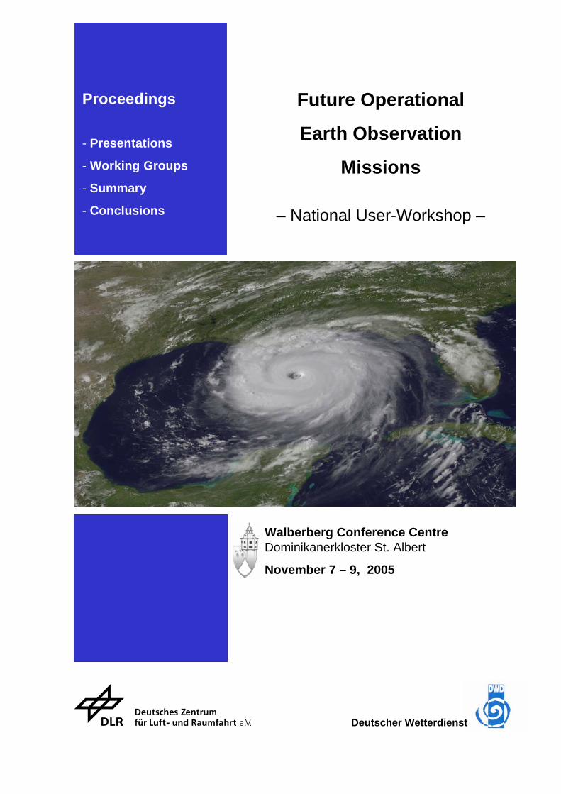
Future Operational
Earth Observation
Missions
– National User-Workshop –
Walberberg Conference Centre Dominikanerkloster St. Albert
November 7 – 9, 2005
Deutscher Wetterdienst

Future Operational Earth Observation
Missions
- National User-Workshop -
Jointly organised by: German Space Agency (DLR)
German Meteorological Service (DWD)
___________________________________________________________________________ Scientific Leader Prof. Hartmut Graßl Max-Planck-Institut für Meteorologie Bundesstraße 55 D-20146 Hamburg Organisation & Coordination Dr. Christian Brüns; Daniela Vogt Deutsches Zentrum für Luft- und Raumfahrt e.V. Königswinterer Straße 522 – 524 D-53227 Bonn ___________________________________________________________________________ This report reflects the contributions of the workshop participants.
They are responsible for the scientific content of the contributions. The copy-right of the presentations remains at the author. In case of further questions, please contact the author directly.
Impressum Printed and published by Deutsches Zentrum für Luft- und Raumfahrt e.V. Raumfahrtmanagement Königswinterer Straße 522 – 524 D-53227 Bonn Editor Dr. Christian Brüns Bonn-Oberkassel, December 2005 The cover page shows the hurricane Katrina imaged with the MODIS instrument. It is based on an image derived from the CIMSS Website (http://cimss.ssec.wisc.edu/tropic/tropic.html).
Table of Contents Page:
Objectives and Results I
Introduction I.1
Report with Conclusions and Recommendations, Prof. H. Graßl I.3
Welcoming Speeches (in German) II
Begrüßung durch den Vorstand des DLR, Dr. L. Baumgarten II.1
Begrüßung durch das Bundesverkehrsministerium, K. Trauernicht II.3
Begrüßung durch den Präsidenten des DWD, W. Kusch II.5
International Activities – GEO/GEOSS & the WMO Space Programme III
The Global Earth Observation System of Systems (GEOSS), U. Gärtner III.1
Planning of Future Meteorological Satellite Systems outside Europe, Dr. Jian Liu III.13
The Future European Earth Observation Missions GMES, MTG, and Post-EPS IV
GMES Space Segment & relevant Earth Explorer Missions, Prof. A. Ginati IV.1
MTG User Requirements, Dr. R. Stuhlmann IV.21
Results of the MTG Pre-Phase A Studies, P. Bensi IV.37
EUMETSAT Activities in Preparation for a Post-EPS System, E. Koenemann IV.47
National Technology Studies Related to a Future Post-EPS System V
The Imaging Radiometer MetImage, Dr. B. Voß V.1
Concept for a Low-Cost EPS-Gapfiller, Dr. H. Lübberstedt V.13
Concept for a Post-EPS Initial Satellite (PEPSIS), Dr. R. Münzenmayer V.23
Results of the Working Groups VI
Working Group on Severe Weather Forecasting, Dr. G. Steinhorst VI.1
Working Group on Numerical Weather Prediction, Dr. N. Bormann VI.7
Working Group on Ocean, Prof. D. Stammer VI.13
Working Group on Atmospheric Chemistry, Prof. H. Fischer VI.19
Working Group on Hydrology, Prof. W. Mauser VI.29
Working Group on Climate, Prof. H. Graßl VI.35
Annex A
Workshop Agenda A.1
List of Participants A.7


Chapter I
Objectives & Results

Introduction DLR and DWD jointly organised a national user-workshop to provide a sound and coordinated basis for the decision process related to the future European earth observation satellite systems in the post-2015 era. This workshop took place at the conference centre of the monastery of Walberberg from 7th to 9th November 2005. The first satellite of the new geostationary meteorological satellite system, Meteosat Second Generation (MSG-1), was successfully launched in 2002. The launch of the second MSG satellite is scheduled for end 2005. Together with MSG-3 and MSG-4, these four satellites will provide operational services at least up to 2015. The first satellite of the EUMETSAT Polar System (EPS) is scheduled for launch in June 2006. The three MetOP satellites are expected to provide operational services up to 2019. The optional EUMETSAT programme Jason-2 – an altimeter mission – is developed in close cooperation with CNES, NOAA, and NASA. The satellite is planned to be launched in 2008. A third generation of geostationary satellites is needed after 2015 to assure operational continuity. Consequently, first studies have been initiated by EUMETSAT and ESA. The user requirements for the Meteosat Third Generation (MTG) have recently been compiled by EUMETSAT while industrial pre-phase A studies have been assigned to Alcatel and EADS Astrium by ESA. The outcome of the user consultation process and first results of the pre-phase A studies were presented on this user-workshop. A mayor goal of this workshop was to consider these results expressing the German priorities for a future, operational, geostationary satellite system. The strategy for an EPS follow-on system (Post-EPS) is currently under discussion at EUMETSAT and its Member States to allow for an operational Post-EPS system in orbit from 2019 onwards. Preparatory activities are being pursued at EUMETSAT and ESA. In addition, national activities covering technical and programmatic studies complementing those of EUMETSAT and ESA were presented on this workshop for consideration. The European initiative Global Monitoring for Environment and Security (GMES) has made progress with respect to the GMES Service Elements (GSE). A proposal for a space segment covering five satellite families will be considered on the ESA ministerial conference in December 2005. Of special interest for this workshop were the so-called “Sentinels” for ocean watch (Sentinel 3) and atmospheric chemistry (Sentinels 4 & 5), which have not yet been defined in great detail. This national user-workshop aims at bringing together operational users, scientists, space industry and “policy-makers”. The workshop comprised introductory presentations covering the above mentioned future operational earth observation missions followed by six working groups on Severe Weather Forecasting / Nowcasting, Numerical Weather Prediction, Ocean, Climate Monitoring, Atmospheric Chemistry, and Hydrology. The workshop proceedings compile the introductory presentations, the results of the individual working groups and the overall conclusions / recommendations of the workshop, which were summarised by Prof. Graßl, the scientific leader of this national user-workshop. We would like to thank all those who have contributed to this workshop. We assume the results provide a good basis for coming decisions on future operational European satellite systems and we are looking forward to the next promising workshop on operational earth observation missions that will be organised in due course. Dr. Christian Brüns Wolfgang Benesch German Space Agency, DLR German Meteorological Service, DWD
I.1

I.2
Report with Conclusions and Recommendations Prof. H. Graßl, Max-Planck-Institut für Meteorologie
Introduction Every citizen now knows that we are living on a small blue planet as satellite images have demonstrated the vulnerability of the Earth system. The development of this system is governed by several substance cycles (water, carbon, nitrogen, sulphur) within which trace substances often play a major role. For instance, so called freezing nuclei, sub-micron particles with a mass fraction of less than one billionth, have an influence in rainy weather and they can even modify the track of low pressure systems. We need to know how the activities of mankind might change this, i.e. we need a global Earth observation system. The cheapest way to achieve this for the atmosphere and the surface of the Earth is observation by satellites because the atmosphere is semi-transparent both for solar and terrestrial radiation. Considering the present costs for Germany with respect to operational meteorological satellites, they range well below a permille of the federal budget or about 10-4 of GDP. The reduction of damage costs due to high impact weather certainly reaches several billions of euros. Hence, investing in a further improved satellite observation system is an advantage for all member countries of EUMETSAT. Building up operational satellite services for other fields such as oceanography, coastal zone management, agriculture, and forestry will with high probability improve the efficiency of economies of all member countries of ESA and EU. Europe, here the European organisation for the exploitation of meteorological satellites (EUMETSAT) and ESA, has reached a similar level to the United States of America in Earth observation from space and is in the lead in a few areas, e.g. Synthetic Aperture Radar (SAR) applications and imaging information from geostationary satellites (Meteosat Second Generation, MSG). Also the use of operational meteorological satellite observations is highly developed at the European Centre for Medium-range Weather Forecasting (ECMWF). The prospects for operational Earth observation satellites have improved recently as Global Monitoring for Environment and Security (GMES), a European initiative, has stimulated the Global Earth Observation System of Systems (GEOSS), an intergovernmental programme to monitor the environment in all its facets, which will need several new operational satellite series beyond the one for meteorology. At this workshop the realm of the discussions is broader than mere academic reasoning about the best operational satellite system for all environmental observations. At the starting point of a new European environmental satellite series, GMES-X, an expert group like the one of this workshop can exert a rather strong influence on future political decision making. Importance of Operational Earth Observation from Space In many disciplines and applications the operational meteorological satellite sensors play a fundamental role in the daily evaluations of Earth observation data from space. Without them daily weather forecasting would be less reliable, especially for 3 to 6 day periods. Seasonal predictions of climate anomalies would show less skill. Nowcasting and very short-term forecasting would be severely hampered, ship routing over nearly a week would probably be absent, air traffic could not be warned against the dangers caused by explosive volcanic eruptions, trend analyses of sea ice cover and of indirect aerosol effects on cloud parameters would not exist.
I.3
Apart from the operational meteorological satellites there is, however, still no such series for other disciplines such as for example oceanography, although its usefulness has already been demonstrated about a decade ago. The national user workshop “Operational Satellite Systems for Earth Observation” had the task to look well beyond the confirmed European satellite series (MSG and European Polar System (EPS)) into the post-2015 era. On the basis of first studies for Meteosat Third Generation (MTG) satellites and EPS-follow-on, all of the six working groups were tasked – taking into account newest scientific knowledge – to propose, from a German perspective, needed operational environmental satellite sensors serving large groups of users and scientific disciplines. The first studies for a GMES satellite series should also be used as input since the European Space Agency (ESA) and the European Commission (EC) would like to transfer capabilities of successful sensors onboard European environmental satellites, such as ERS-1, ERS-2, and Envisat, into an operational phase. The groups should also consider infra-structural issues. Thus the workshop had a considerable workload, but it seemed well-suited for this task as nearly all organisations mentioned – the scientific community, the German Meteorological Service (DWD), and the German Space Agency (DLR) – were represented by their experts. Goals of the Workshop Before the workshop started the organizers had issued a two-paged document in order to guide the group and plenary discussions. Hence, the working group leaders and attendants were in advance informed of the following goals of the workshop: Remarks on new technological approaches and their transfer into an operational environment
• agreement on national user requirements for future operational satellite systems for Earth observation to be launched after 2015 going beyond operational meteorological satellites, but including them with priority
• assessment of MTG pre-phase A studies and first activities for the EPS follow-on series as well as first GMES satellite building blocks for “Ocean-watch” and “Atmospheric Chemistry”
• assessment of existing European environmental satellite sensors in order to point to improvements needed for future operational satellite series
• inclusion of ground segment as well as data processing and archiving Results of the Working Groups The results and recommendations of the six working groups Severe Weather Forecasting, Numerical Weather Prediction, Ocean, Atmospheric Chemistry, Hydrology, and Climate are presented in Chapter VI. Overall Conclusions
• long homogeneous global and regional time series of radiances and derived geophysical parameters are the key for a successful environmental monitoring as basis for intelligent decision-making.
• adoption of the satellite climate monitoring principles proposed by the Global Climate Observing System (GCOS)
• onboard calibration for all spectral ranges (UV, visible, SWIR, TIR, and microwaves) • intercalibration of satellite series should become a routine task for space agencies
I.4
• recalibration of archived radiances after intercalibration attempts is a standard service • more emphasis for reprocessing in intervals agreed on • European contribution to a Global Precipitation Mission (EGPM) should become an
operational sensor package now • better access to better re-analysed data
Main Recommendations European Polar System follow-on (EPS follow-on)
• Instead of a bridging satellite (PEPSIS), a fourth Meteorological Operational Satellite (METOP4) should provide continuity until an EPS follow-on series is ready for launch.
• The proposed bridging satellite (PEPSIS), if necessary at all, should not fall short of the capacities of the METEOP series, i.e. microwave sounding capacity has to be included besides the sounder IASI and the imager (AVHRR-type)
Satellite Series for Global Monitoring for Environment and Security (GMES-N)
• Europe has to establish leadership in construction, operations, and exploitation of operational meteorological satellites through ESA, EUMETSAT, and ECMWF for all future GMES-N satellites.
• Besides global climate change, major global change issues such as air and water pollution, soil degradation, loss of biodiversity need operational monitoring for better decision-making, thus needing an operational satellite series envisaged in the GMES-N satellites from Europe, jointly to be implemented by ESA, EUMETSAT, and the European Union.
• International co-ordination of national services should be established such as to meteorological services are a prerequisite for the efficient use of GMES-N monitoring data.
• EUMETSAT has to be tasked to care for the operational service for GMES-N satellites whenever atmospheric, sea surface, and meteorological land surface parameters are the main observables.
• The EU, ESA, and EUMETSAT should soon agree on implementation rules for all GMES-N satellites.
Comments on all Operational Satellite Series
• Intercalibration of satellites in a series as well as absolute calibration of a single satellite needs much more attention of space agencies in order to reach (climate) monitoring quality accurate enough for trend analyses. This task comprises: o re-analyses whenever major algorithm improvement has occurred o data archiving and dissemination centres including the experimental satellite data of
the forerunner sensors, e.g. ERS1/2 and Envisat, for the forth-coming GMES-N sensors in order to have trend analyses capacity from 1991 onwards
• Continuing free and open access to all data up to level 2, as with present operational meteorological satellites, is needed to guarantee full use for the benefit of many countries. This would turn European satellite series into one of the most efficient investments for the security of the citizens and for the full use and security of the infrastructure.
I.5

I.6

Chapter II
Welcoming Speeches
(in German)

Begrüßung durch den Vorstand des DLR Herr Dr. Ludwig Baumgarten
Sehr geehrte Damen und Herren, für das Deutsche Zentrum für Luft- und Raumfahrt begrüße ich Sie auf der nationalen Arbeitstagung über operationelle Satellitensysteme der Erdüberwachung. Wir freuen uns über das ungeteilte und große Interesse für diese Veranstaltung bei
- Behörden, - Wissenschaft, - Industrie - und nicht zuletzt bei den internationalen Organisationen
o EUMETSAT, o ESA, o dem Europäischen Zentrum für mittelfristige Wettervorhersage (EZMW) o und der World Meterological Organization (WMO).
Gleich zu Anfang möchte ich mich für die Unterstützung des Bundesministeriums für Verkehr, Bau- und Wohnungswesen bedanken, in deren Auftrag das DLR Raumfahrtmanagement diese Veranstaltung gemeinsam mit dem Deutschen Wetterdienst organisiert hat. Auch dem Deutschen Wetterdienst möchte ich an dieser Stelle für die gute Zusammenarbeit bei der Vorbereitung danken. Vor genau 5 Jahren sind wir schon einmal hier im Kloster Walberberg zusammen gekommen, um über die Nachfolger der derzeitigen meteorologische Satellitensysteme Meteosat Zweite Generation und das EUMETSAT Polarsystem (also die MetOP Satelliten) zu diskutieren. Zu jener Zeit waren diese Nachfolgesysteme noch in weiter Ferne. Es verlangte damals schon einiges an Mut und Phantasie, bereits Jahre vor dem Start des ersten Satelliten der zweiten Generation Meteosat und des ersten MetOP Satelliten über deren Nachfolgeprogramme zu diskutieren und hierzu Nutzeranforderungen aus deutscher Sicht zu definieren. Dennoch war die Tagung hier in Walberberg überaus erfolgreich: Die Ergebnisse
- sind international auf höchstes Interesse gestoßen, - haben zahlreiche weiterführende Diskussionen angeregt - und den internationalen Definitionsprozess der zukünftigen meteorologischen
Satellitensysteme Europas in Schwung gebracht. Meine Damen und Herren, seit dem ersten Walberberg-Workshop hat sich viel getan. Der erste Satellit der zweiten Generation Meteosat wurde im August 2002 gestartet und unter dem Namen Meteosat 8 erfolgreich in Betrieb genommen. Er bietet den operationellen Nutzern und der Wissenschaft seitdem eine enorm verbesserte Datengrundlage. Der zweite Satellit wird voraussichtlich noch in diesem Jahr vom europäischen Weltraumbahnhof Kourou gestartet. Mit dem dritten und vierten Satelliten wird der operationelle Betrieb der zweiten Generation Meteosat bis 2015 gesichert sein. Anschließend soll eine dritte Satellitengeneration den erneuten technischen Fortschritt umsetzen und wiederum für einen Qualitätssprung der raumgestützten meteorologischen Informationen sorgen. Die ersten technologischen Voruntersuchungen für diese 3. Generation von Meteosat sind im Auftrag der ESA durchgeführt worden und werden Ihnen im Laufe dieser Veranstaltung vorgestellt. Auch der erste Satellit des EUMETSAT Polarsystems – MetOP-A – steht kurz vor dem Start. Er wird einen weiteren wichtigen europäischen Beitrag im globalen Netz der Wetter- und
II.1
Umweltsatelliten leisten. Insgesamt umfasst das EUMETSAT Polarsystem drei MetOP Satelliten, die bis ca. 2019 gemeinsam mit den US-amerikanischen NOAA Satelliten ein „Initial Joint Polar System“ bilden. Die Amerikaner haben ihr Nachfolgesystem bereits definiert. Der europäische Beitrag im Rahmen einer Nachfolge-Generation zum EUMETSAT Polarsystem ist noch nicht klar zu erkennen. Auch hierzu erwarten wir von dieser Veranstaltung wichtige Impulse. Das Deutsche Zentrum für Luft- und Raumfahrt engagiert sich seit Jahren mit zunehmender Intensität in der Erderkundung. Das DLR Raumfahrtmanagement hat beispielsweise erste technische Untersuchungen zur Konzeption eines Kleinsatelliten in Auftrag gegeben, um einen sicheren Übergang zu einem europäischen, meteorologischen Nachfolgesystem im polaren Orbit zu gewährleisten. Die Ergebnisse dieser Untersuchungen werden in dieser Veranstaltung erstmals einem breiteren Fachpublikum vorgestellt. Im nationalen Raumfahrtprogramm wird durch das DLR auch die Entwicklung innovativer Technologien gefördert. Im Zusammenhang mit dieser Veranstaltung ist insbesondere das innovative MetImage Konzept für ein abbildendes Radiometer zu nennen, das Ihnen während dieser Arbeitstagung vorgestellt werden wird. Die Raumfahrt verhilft zu einem enormen Fortschritt bei dem Verständnis und Verstehen der Vorgänge auf unserem Planeten. Gerade in diesen Zeiten eines globalen Klimawandels sind umfassende Beobachtungen des Zustands unseres Planeten von fundamentaler Bedeutung. Die diesjährige Hurrikan-Saison in Amerika und die Taifune im pazifischen Raum mit ihren furchtbaren Auswirkungen auf dem Festland zeigen nachdrücklich die Bedeutung von Satellitensystemen im Routinebetrieb. Nicht nur in diesem Zusammenhang wird eine bessere Vernetzung und Koordination der weltweiten Beobachtungssysteme immer wichtiger. Die Meteorologie ist seit langem global gut organisiert und in dieser Hinsicht ein Vorreiter für andere Bereiche – insbesondere für GEOSS und GMES. Auf international breiter Basis entsteht derzeit nach dem Vorbild der Meteorologie ein Globales Erdbeobachtungssystem von Systemen – kurz GEOSS, das den globalen Datenaustausch und die Koordinierung der internationalen Erdbeobachtungsprogramme verbessern soll. Die europäische Initiative zur globalen Umwelt- und Sicherheitsüberwachung – kurz GMES – wird einen zentralen Beitrag Europas zu GEOSS liefern. Der Fokus der Initiative liegt aber darauf, eine eigenständige Beobachtungskapazität zur Entscheidungsunterstützung europäischer Umwelt- und Sicherheitspolitiken zu etablieren. Die Initiative ist mit der Entwicklung eines breiten Portfolios von marinen Diensten, Atmosphären- und Landanwendungen und Unterstützung zum Krisenmanagement erfolgreich angelaufen. Die bei der ESA anstehenden Entscheidungen zum Weltraumsegment für GMES im kommenden Monat stellen einen wichtigen Meilenstein dar, um die notwendigen langfristigen Beobachtungssysteme sicherzustellen. Meine Damen und Herren, Diese Tagung ist keine reine Informationsveranstaltung. Ihr wesentliches Ziel ist es, einen Beitrag zur Definition der nationalen Anforderungen an die künftigen operationellen Erdbeobachtungsmissionen zu leisten. Entscheidend ist, dass Sie als Satellitennutzer aktiv in allen Definitionsphasen mitarbeiten, um sicherzustellen, dass am Ende auch Ihre Bedürfnisse befriedigt werden. Ich wünsche Ihnen für die Tagung viel Erfolg und hoffe, dass das Forum, wie bereits auf dem ersten Walberberg Workshop, für fruchtbare Diskussionen genutzt wird, um die Weichen für die kommenden Missionen der Erdbeobachtung zu stellen. Möge es gelingen.
II.2
Begrüßung durch den Leiter des Referats LS 14 Bundesministerium für Verkehr, Bau und Stadtentwicklung
Herr Karl Trauernicht
Sehr geehrte Damen und Herren, mit diesem Workshop haben wir uns das Ziel gesetzt, in der Vorbereitung weiterer Programme der Erdfernerkundung einen deutlichen Fortschritt zu erzielen. Um hier voranzukommen, sind wir, wie ich meine, gut aufgestellt: - Es liegen Erfahrungen aus einer Reihe von Anwendungen der Erdfernerkundung vor, - Mit EUMETSAT haben wir einen Betreiber, der das Know How des operationellen Dienstes
beherrscht und auch für neue Anwendungen gut gerüstet ist, - die nationalen Wetterdienste haben sich auf konkrete Kooperationen verständigt, um in der
Nutzung von Satellitendaten für meteorologischen Anwendungen effizient vorzugehen, - im Rahmen von GMES sind weitere Vorhaben der Erdbeobachtung definiert, die bei der ESA
inzwischen konkret geplant werden, - mit dem Aufbau eines globalen Erdbeobachtungssystems entsteht das „Gebäude“, welches
in einer Gesamtschau die verschiedenen Dienste zusammenfasst und für die Politikberatung und die Forschung bereithält,
- wir verfügen auch in Deutschland über leistungsfähige Industrieunternehmen, die ihre Produkte in den Wettbewerb einbringen und dem Standort Deutschland einen angemessenen Platz in der Raumfahrt geben,
- nicht zuletzt haben wir im DLR einen Partner, der uns in Planung und Umsetzung kompetent berät.
Dem DLR und dem DWD möchte ich für die gute Vorbereitung dieses Workshops danken. Mein besonderer Dank gilt Herrn Prof. Grassl für seine Bereitschaft, die wissenschaftliche Leitung dieser Veranstaltung zu übernehmen. Sie haben in den zurückliegenden Jahren immer wieder auf die Bedeutung der satellitengestützten Datenerhebung hingewiesen und es sind nicht nur die Wetterdienste, die Ihnen für Ihr Engagement dankbar sind. Die Erdfernerkundung braucht auch in Zukunft die Unterstützung von Politik und Wissenschaft. Sorge bereitet mir, dass die Erdfernerkundung mit anderen Feldern der Raumfahrt in einem harten Wettbewerb um knappe Ressourcen steht. Von allen Raumfahrtaktivitäten leistet die Erdfernerkundung einen unmittelbaren und großen Beitrag für die Daseinsvorsorge auf diesem Planeten. Parlament und Bundesregierung stehen daher in der besonderen Verantwortung, dafür zu sorgen, dass die Erdfernerkundung auch in Zukunft ihren Stellenwert bewahren kann. So habe ich die Hoffnung, dass sich Deutschland trotz schwieriger Haushaltslage auf der ESA-Ministerratskonferenz im Dezember in Berlin dazu durchringen wird, das Erdbeobachtungsprogramm in akzeptabler Höhe zu zeichnen. Gleichzeitig sind wir aber auch aufgerufen, bei Planung und Umsetzung zukünftiger Programme dem Kostenmanagement besondere Aufmerksamkeit zu schenken. Die für diesen Workshop vorgesehenen thematischen Schwerpunkte vermitteln einen Eindruck von der Breite der Anwendungen der Erdfernerkundung. Ich bin davon überzeugt, dass mit dem weiteren Voranschreiten der Arbeiten für den Aufbau eines globalen Erdbeobachtungssystems Stellenwert und Dynamik der Erdbeobachtung noch weiter zunehmen werden. Uns allen wünsche ich, dass wir am Mittwoch beim Rückblick auf den Workshop allen Anlass haben, ein positives Resultat dieser Veranstaltung zu ziehen.
II.3

II.4
Begrüßung durch den amtierenden Präsidenten des DWD Herr Wolfgang Kusch
Sehr geehrter Herr Dr. Baumgarten, sehr geehrter Herr Trauernicht, verehrter Herr Prof. Graßl, meine Damen und Herren, ich sehe dieses Treffen als Folgeveranstaltung einer ähnlichen Konferenz im November 2000 an gleichem Ort. Folgende Gründe sprechen für diese Veranstaltung:
1. Bei EUMETSAT stehen im kommendem Jahr Entscheidungen zu den Machbarkeitsstudien (Phase-A-Studien) für eine 3. Meteosat -Generation an;
2. Bei EUMETSAT laufen die ersten Planungen zu einem Nachfolgesystem zum EUMETSAT Polar System (EPS) an – derzeit werden die Nutzeranforderungen zusammengetragen;
3. Auch bei ESA stehen Entscheidungen zu zukünftigen Aktivitäten im Bereich der Erdbeobachtung an. Es ist uns wichtig, dass die ESA weiterhin eine bedeutende Rolle auf dem Gebiet der Entwicklung und Erprobung neuer Weltraumtechnologien und Missionen zur Erdbeobachtung spielen kann.
4. Bei EU und ESA werden Entscheidungen zu GMES (Global Monitoring for the Environment and Security) erwartet, ebenso eine Konsolidierung der Beiträge Europas zum globalen System der Systeme für die Erdbeobachtung.
Als Ziel der Veranstaltung sehe ich:
• dass die Anforderungen der Nutzer in Deutschland an zukünftige operationelle Satellitensysteme abgestimmt und konsolidiert werden;
• die Erarbeitung von nationalen Positionen, die dann nach Möglichkeit einhellig von allen mitgetragen und vertreten werden;
• dass eine fachliche Basis geschaffen wird mit Empfehlungen für nationale Entscheidungsträger und Delegierte in internationalen Gremien.
Zur Bedeutung der Satelliten für den DWD: Der Deutsche Wetterdienst nutzt seit 1966 Satellitendaten. Sie sind ein wesentlicher und unverzichtbarer Bestandteil des meteorologischen Beobachtungssystems, Satellitenfernerkundung und andere Meßsysteme ergänzen sich gegenseitig. • Satellitendaten liefern die Eingangsdaten unter anderem für die numerische
Wettervorhersage, genauer für die Datenassimilation, zur möglichst korrekten Erfassung der Ausgangssituation der Simulationsrechnungen.
• Im praktischen Wettervorhersagedienst dienen sie zur Erfassung und Verfolgung gefährlicher Wetterereignisse, für möglichst präzise Vorhersagen des genauen Orts, Zeitpunkts und der Intensität gefährlicher Wetterereignisse im Bereich von wenigen Stunden (sog. Nowcasting) sowie zur Überwachung der Richtigkeit der numerischen Wettervorhersagen.
• Der DWD nutzt auch Satelliteninformationen zur Überwachung der Zusammensetzung der Atmosphäre. Das Meteorologische Observatorium Hohenpeißenberg des DWD ist am EUMETSAT Ozon-SAF mit beteiligt und leistet wesentliche Beiträge zur Verifizierung und Validierung von den Spurengasmessungen der Satelliten.
• Der DWD nutzt Satellitendaten im Bereich des Überwachung des Klimas. Mit der Leitfunktion der EUMETSAT „Satellite Application Facility on Climate Monitoring“, kurz
II.5
„Klima-SAF“, hat der DWD eine besondere Verantwortung und Spitzenstellung im relativ neuen Bereich der Satellitenklimatologie. Das SAF-Programm wird zukünftig wesentlich den operationellen Betrieb der Wetterdienste mitgestalten und ist von besonderer Bedeutung für die Zukunft.
Sehr verehrte Damen und Herren, und wie sieht die Zukunft aus? Jede neue Satellitengeneration wird das Nutzungsspektrum, nicht nur für die Meteorologie, enorm erweitern:
• Mit den multispektralen Daten und einer zeitlichen Wiederholrate von 15 Minuten liefert die Zweite Meteosat-Generation eine Vielzahl breiterer Nutzungsmöglichkeiten als bisher. Das Nutzungspotential dieser neuen Meteosat-Generation ist derzeit jedoch noch nicht voll ausgeschöpft und es laufen noch entsprechende Forschungs- und Entwicklungsaktivitäten.
• Der Start von MSG-2, also dem 2. Satelliten der neuen Meteosat-Generation ist derzeit für den 20. Dezember 2005 geplant. Noch 2 weitere MSG-Satelliten werden folgen.
• Der erste polarumlaufende Satellit von EUMETSAT mit dem Namen METOP ist für Ende Juni 2006 vorgesehen. Insgesamt ist der Start von 3 METOP-Satelliten beschlossen.
• Auch wenn die Zweite Meteosat Generation erst seit 2004 voll operationell ist und der erste der polarumlaufenden Satelliten von EUMETSAT noch nicht einmal im Orbit ist, so muss jetzt schon mit den Vorbereitungen der Nachfolgegenerationen begonnen werden. Es werden z.T. technologische Neuentwicklungen nötig, die Beschlussprozeduren sind sehr langwierig, wegen der erforderlichen Einstimmigkeit bei EUMETSAT oft zu langwierig, und wir sind mit den Planungen jetzt schon unter Zeitdruck.
• Die Dritte Meteosat- Generation und das EPS-Nachfolgesystem (= das Nachfolgesystem für die METOP-Satelliten) soll etwa im Zeitraum von 2015 bis 2030 im Einsatz sein.
Meine Damen und Herren, • dieser Workshop ist eine nationale Veranstaltung. Wichtig ist aber bei den Planungen auch
das internationale Umfeld im Bewusstsein zu haben und die Planungen außereuropäischer Satellitenbetreiben mit zu berücksichtigen, soweit dies möglich ist. Wir freuen uns daher, dass eine Vertreterin vom WMO-Sekretariat an dieser Veranstaltung teil nimmt.
• Wichtig ist auch, dass bei dieser Veranstaltung realistische Empfehlungen und Visionen entwickelt werden, d.h. dass zukünftige operationelle Satelliten- Erdbeobachtungssysteme diskutiert werden, die einerseits weitgehend den Nutzerbedarf abdecken, andererseits aber auch noch finanzierbar sind. Gerade in der derzeitigen Lage der öffentlichen Haushalte kommt dem Aspekt der Finanzierbarkeit eine besondere Bedeutung zu.
Meine Damen und Herren, • in dem vorgenannten Sinne wünsche ich der Veranstaltung viel Erfolg. • Das Treffen ist eine gemeinsame Veranstaltung von DLR und DWD. Die Hauptlast trägt
jedoch das DLR, sowohl vom der Organisation als auch den Kosten her. Ich möchte daher dem DLR meinen besonderen Dank hierfür aussprechen.
• Mein Dank gilt aber auch den Leitern den der Arbeitsgruppen und all denen, die aktiv an der Vorbereitung der Veranstaltung beteiligt waren.
• Doch nun Schluss mit den Begrüßungsworten. Die fachliche Leitung der gesamten Veranstaltung liegt bei Prof. Graßl und wir freuen uns jetzt auf seinen Übersichtsvortrag „Satelliten und das System Erde“.
II.6
Chapter III
International Activities
GEO/GEOSS & the WMO Space Programme

Global Earth Observation
System of Systems (GEOSS)
U. Gärtner
III.1

III.2
GEOSS
Global Earth Observation System of Systemseine Initiative der
GEOGroup on Earth Observation
H. Staudenrausch, W. Kleine-Beek, U. Gärtner
Gliederung
Mandat und HistorieZielsetzungAktueller StandInternationale AktivitätenEuropäischer BeitragNationale GEOSS-Aktivitäten und ProblemstellungINSPIRE- RichtlinieIMAGI und GDI-DE
III.3
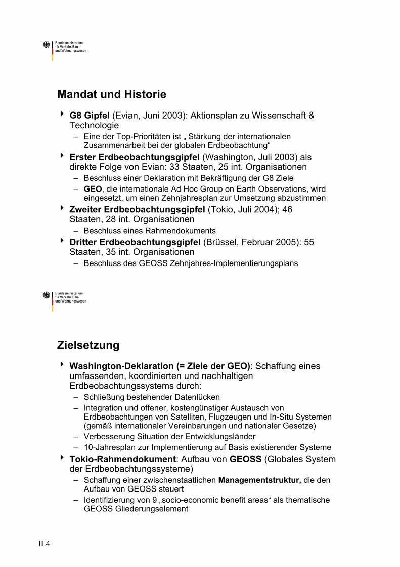
Mandat und Historie
G8 Gipfel (Evian, Juni 2003): Aktionsplan zu Wissenschaft & Technologie– Eine der Top-Prioritäten ist „ Stärkung der internationalen
Zusammenarbeit bei der globalen Erdbeobachtung“Erster Erdbeobachtungsgipfel (Washington, Juli 2003) als direkte Folge von Evian: 33 Staaten, 25 int. Organisationen– Beschluss einer Deklaration mit Bekräftigung der G8 Ziele– GEO, die internationale Ad Hoc Group on Earth Observations, wird
eingesetzt, um einen Zehnjahresplan zur Umsetzung abzustimmenZweiter Erdbeobachtungsgipfel (Tokio, Juli 2004); 46 Staaten, 28 int. Organisationen– Beschluss eines Rahmendokuments
Dritter Erdbeobachtungsgipfel (Brüssel, Februar 2005): 55 Staaten, 35 int. Organisationen– Beschluss des GEOSS Zehnjahres-Implementierungsplans
Zielsetzung
Washington-Deklaration (= Ziele der GEO): Schaffung eines umfassenden, koordinierten und nachhaltigen Erdbeobachtungssystems durch:– Schließung bestehender Datenlücken– Integration und offener, kostengünstiger Austausch von
Erdbeobachtungen von Satelliten, Flugzeugen und In-Situ Systemen (gemäß internationaler Vereinbarungen und nationaler Gesetze)
– Verbesserung Situation der Entwicklungsländer– 10-Jahresplan zur Implementierung auf Basis existierender Systeme
Tokio-Rahmendokument: Aufbau von GEOSS (Globales System der Erdbeobachtungssysteme)– Schaffung einer zwischenstaatlichen Managementstruktur, die den
Aufbau von GEOSS steuert– Identifizierung von 9 „socio-economic benefit areas“ als thematische
GEOSS Gliederungselement
III.4
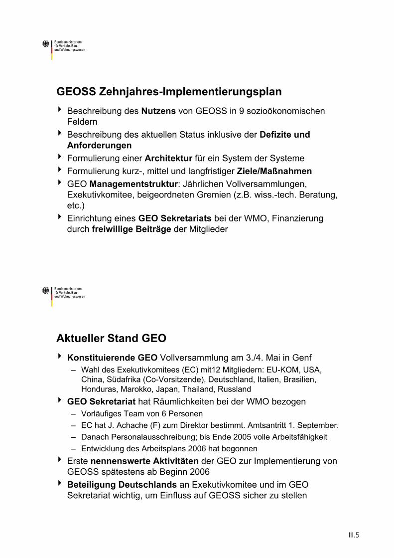
GEOSS Zehnjahres-ImplementierungsplanBeschreibung des Nutzens von GEOSS in 9 sozioökonomischen FeldernBeschreibung des aktuellen Status inklusive der Defizite und AnforderungenFormulierung einer Architektur für ein System der Systeme Formulierung kurz-, mittel und langfristiger Ziele/MaßnahmenGEO Managementstruktur: Jährlichen Vollversammlungen, Exekutivkomitee, beigeordneten Gremien (z.B. wiss.-tech. Beratung, etc.)Einrichtung eines GEO Sekretariats bei der WMO, Finanzierung durch freiwillige Beiträge der Mitglieder
Aktueller Stand GEOKonstituierende GEO Vollversammlung am 3./4. Mai in Genf– Wahl des Exekutivkomitees (EC) mit12 Mitgliedern: EU-KOM, USA,
China, Südafrika (Co-Vorsitzende), Deutschland, Italien, Brasilien, Honduras, Marokko, Japan, Thailand, Russland
GEO Sekretariat hat Räumlichkeiten bei der WMO bezogen– Vorläufiges Team von 6 Personen– EC hat J. Achache (F) zum Direktor bestimmt. Amtsantritt 1. September. – Danach Personalausschreibung; bis Ende 2005 volle Arbeitsfähigkeit– Entwicklung des Arbeitsplans 2006 hat begonnen
Erste nennenswerte Aktivitäten der GEO zur Implementierung von GEOSS spätestens ab Beginn 2006Beteiligung Deutschlands an Exekutivkomitee und im GEO Sekretariat wichtig, um Einfluss auf GEOSS sicher zu stellen
III.5
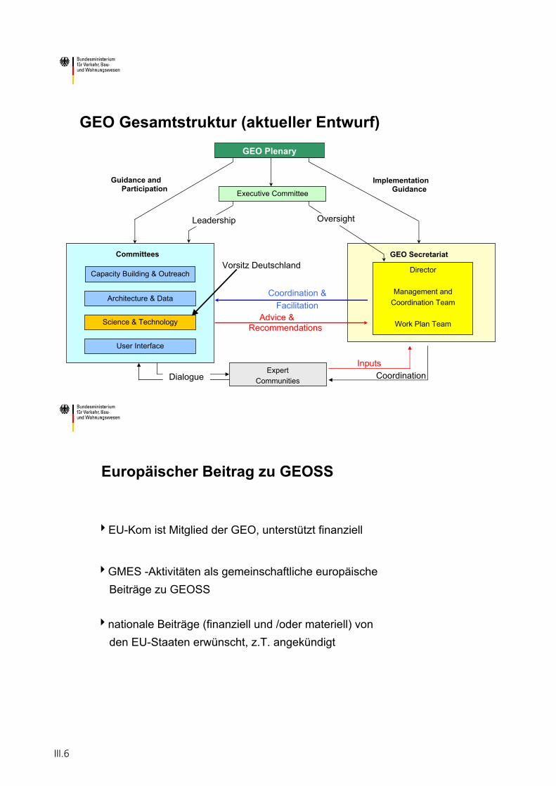
GEO Gesamtstruktur (aktueller Entwurf)
Coordination
GEO Plenary
Capacity Building & Outreach
Architecture & Data
Science & Technology
Executive Committee
Director
Management andCoordination Team
Work Plan Team
ExpertCommunities
Advice & Recommendations
Coordination &Facilitation
Leadership Oversight
ImplementationGuidance
Guidance and Participation
GEO SecretariatCommittees
User Interface
DialogueInputs
Vorsitz Deutschland
GMES -Aktivitäten als gemeinschaftliche europäische Beiträge zu GEOSS
nationale Beiträge (finanziell und /oder materiell) vonden EU-Staaten erwünscht, z.T. angekündigt
Europäischer Beitrag zu GEOSS
EU-Kom ist Mitglied der GEO, unterstützt finanziell
III.6
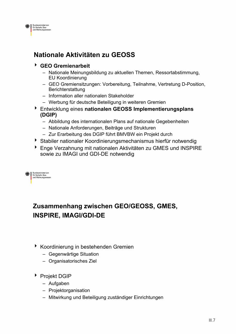
Nationale Aktivitäten zu GEOSSGEO Gremienarbeit– Nationale Meinungsbildung zu aktuellen Themen, Ressortabstimmung,
EU Koordinierung– GEO Gremiensitzungen: Vorbereitung, Teilnahme, Vertretung D-Position,
Berichterstattung– Information aller nationalen Stakeholder– Werbung für deutsche Beteiligung in weiteren Gremien
Entwicklung eines nationalen GEOSS Implementierungsplans (DGIP)– Abbildung des internationalen Plans auf nationale Gegebenheiten– Nationale Anforderungen, Beiträge und Strukturen– Zur Erarbeitung des DGIP führt BMVBW ein Projekt durch
Stabiler nationaler Koordinierungsmechanismus hierfür notwendigEnge Verzahnung mit nationalen Aktivitäten zu GMES und INSPIRE sowie zu IMAGI und GDI-DE notwendig
Zusammenhang zwischen GEO/GEOSS, GMES,INSPIRE, IMAGI/GDI-DE
Koordinierung in bestehenden Gremien – Gegenwärtige Situation – Organisatorisches Ziel
Projekt DGIP – Aufgaben– Projektorganisation– Mitwirkung und Beteiligung zuständiger Einrichtungen
III.7
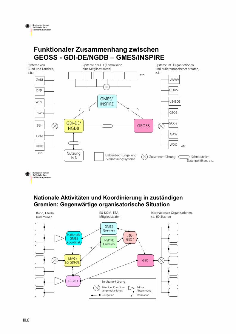
Funktionaler Zusammenhang zwischen GEOSS - GDI-DE/NGDB – GMES/INSPIRE
GDI-DE/NGDB
Systeme vonBund und Ländern,z.B.:
GEOSS
GMES/INSPIRE
Systeme int. Organisationenund außereuropäischer Staaten,z.B.:
SchnittstellenDatenpolitiken, etc.
Nutzungin D
Systeme der EU (Kommissionplus Mitgliedstaaten)
etc.
Zusammenführung
ZADI
DFD
WSV
DWD
BSH
LVAs
UDKs
Erdbeobachtungs- undVermessungssysteme
WWW
GOOS
US-IEOS
GTOS
GCOS
GAW
WDC
etc.
etc.
D-GEO
NationaleGMES
Koordinat.
Nationale Aktivitäten und Koordinierung in zuständigen Gremien: Gegenwärtige organisatorische Situation
IMAGI/LG GDI-DE
Bund, LänderKommunen
GEO
GMESGremien
Internationale Organisationen,ca. 60 Staaten
EU-KOM, ESA,Mitgliedstaaten
„EU-GEO“
Ständiger Koordina-tionsmechanismus
INSPIREGremien
?
Ad hocAbstimmung
Delegation Information
Zeichenerklärung
III.8
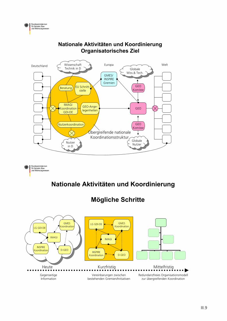
Nationale Aktivitäten und Koordinierung Organisatorisches Ziel
IMAGIKoordination
GDI-DE
Deutschland
GEO
GMES/INSPIREGremien
WeltEuropa
GEO-Ange-legenheiten
EU Schnitt-stelle
Nutzerkoordination GEOKomitee
GEOKomitee
Beratung
Nutzerin D
Nutzerin D
GlobaleWiss.& Tech.
GlobaleWiss.& Tech.
GlobaleNutzer
GlobaleNutzer
WissenschaftTechnik in D
WissenschaftTechnik in D
Übergreifende nationaleKoordinationsstruktur
Nationale Aktivitäten und Koordinierung
Mögliche Schritte
LG GDI-DE
D-GEO
GMESKoordination
INSPIREKoordination
IMAGI
LG GDI-DE
D-GEO
GMESKoordination
INSPIREKoordination
IMAGI
Vereinbarungen zwischenbestehenden Gremien/Initiativen
Heute Kurzfristig Mittelfristig
GegenseitigeInformation
Redundanzfreies Organisationsmodellzur übergreifenden Koordination
III.9
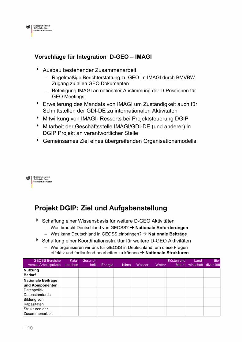
Vorschläge für Integration D-GEO – IMAGI
Ausbau bestehender Zusammenarbeit– Regelmäßige Berichterstattung zu GEO im IMAGI durch BMVBW
Zugang zu allen GEO Dokumenten – Beteiligung IMAGI an nationaler Abstimmung der D-Positionen für
GEO Meetings Erweiterung des Mandats von IMAGI um Zuständigkeit auch für Schnittstellen der GDI-DE zu internationalen AktivitätenMitwirkung von IMAGI- Ressorts bei Projektsteuerung DGIPMitarbeit der Geschäftsstelle IMAGI/GDI-DE (und anderer) in DGIP Projekt an verantwortlicher StelleGemeinsames Ziel eines übergreifenden Organisationsmodells
Projekt DGIP: Ziel und Aufgabenstellung
Schaffung einer Wissensbasis für weitere D-GEO Aktivitäten– Was braucht Deutschland von GEOSS? Nationale Anforderungen– Was kann Deutschland in GEOSS einbringen? Nationale Beiträge
Schaffung einer Koordinationsstruktur für weitere D-GEO Aktivitäten– Wie organisieren wir uns für GEOSS in Deutschland, um diese Fragen
effektiv und fortlaufend bearbeiten zu können Nationale StrukturenGEOSS Bereiche
versus ArbeitspaketeKata-
strophenGesund-
heit Energie Klima Wasser WetterKüsten und
MeereLand-
wirtschaft Bio-
diversitätNutzung BedarfNationale Beiträge und Komponenten Datenpolitik DatenstandardsBildung von KapazitätenStrukturen der Zusammenarbeit
III.10
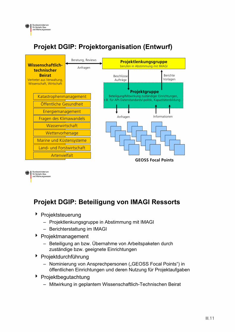
BeschlüsseAufträge
Wissenschaftlich-technischer
BeiratVertreter aus Verwaltung,Wissenschaft, Wirtschaft
Projekt DGIP: Projektorganisation (Entwurf)
ProjektgruppeBeteiligung/Mitwirkung zuständiger Einrichtungen,
z.B. für APs Datenstandards/-politik, Kapazitätenbildung...
Marine und Küstensysteme
Projektlenkungsgruppe berufen in Abstimmung mit IMAGI
Wettervorhersage
Land- und Forstwirtschaft
Wasserwirtschaft
Fragen des Klimawandels
Energiemanagement
Öffentliche Gesundheit
Katastrophenmanagement
Artenvielfalt
BerichteVorlagen
Beratung, Reviews
Anfragen
GEOSS Focal Points
Anfragen Informationen
Projekt DGIP: Beteiligung von IMAGI Ressorts
Projektsteuerung– Projektlenkungsgruppe in Abstimmung mit IMAGI– Berichterstattung im IMAGI
Projektmanagement– Beteiligung an bzw. Übernahme von Arbeitspaketen durch
zuständige bzw. geeignete EinrichtungenProjektdurchführung– Nominierung von Ansprechpersonen („GEOSS Focal Points“) in
öffentlichen Einrichtungen und deren Nutzung für ProjektaufgabenProjektbegutachtung– Mitwirkung in geplantem Wissenschaftlich-Technischen Beirat
III.11

III.12
Panning of Future Meteorological Satellite Systems outside Europe
Dr. Jian Liu
WMO
III.13

III.14
Planning of Future Meteorological Satellite Systems outside Europe
Dr Jian LiuWMO Space Programme
World Meteorological Organization
• WMO Space Programme
• The present space-based GOS (2005)
• Approved plans
III.15
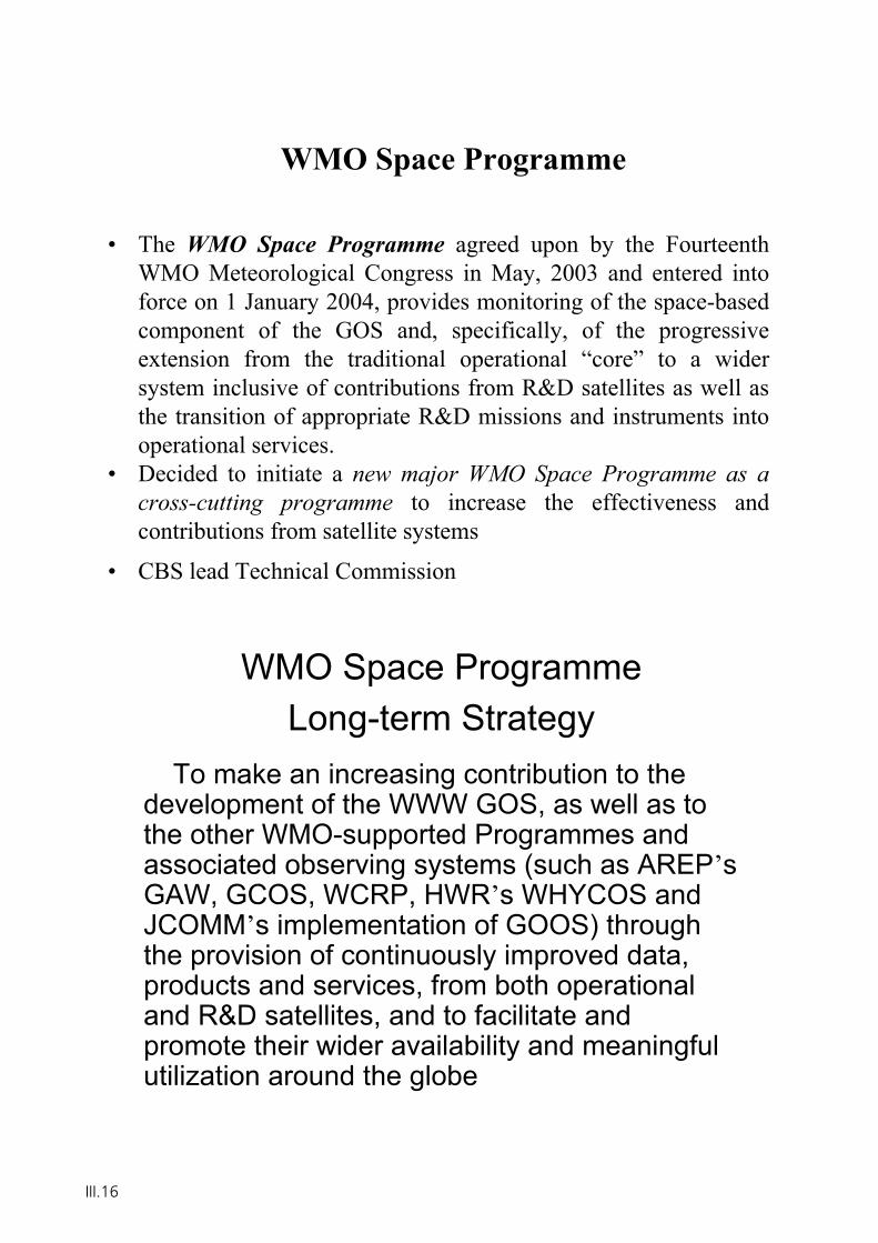
WMO Space Programme
• The WMO Space Programme agreed upon by the Fourteenth WMO Meteorological Congress in May, 2003 and entered into force on 1 January 2004, provides monitoring of the space-based component of the GOS and, specifically, of the progressive extension from the traditional operational “core” to a wider system inclusive of contributions from R&D satellites as well asthe transition of appropriate R&D missions and instruments into operational services.
• Decided to initiate a new major WMO Space Programme as a cross-cutting programme to increase the effectiveness and contributions from satellite systems
• CBS lead Technical Commission
WMO Space Programme Long-term Strategy
To make an increasing contribution to the development of the WWW GOS, as well as to the other WMO-supported Programmes and associated observing systems (such as AREP’sGAW, GCOS, WCRP, HWR’s WHYCOS and JCOMM’s implementation of GOOS) through the provision of continuously improved data, products and services, from both operational and R&D satellites, and to facilitate and promote their wider availability and meaningful utilization around the globe
III.16
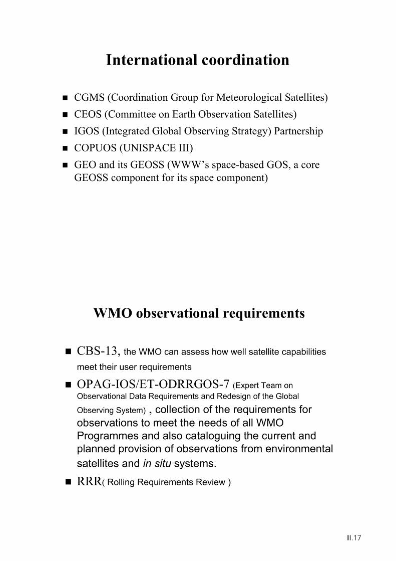
International coordination
CGMS (Coordination Group for Meteorological Satellites)CEOS (Committee on Earth Observation Satellites)IGOS (Integrated Global Observing Strategy) PartnershipCOPUOS (UNISPACE III)GEO and its GEOSS (WWW’s space-based GOS, a core GEOSS component for its space component)
WMO observational requirements
CBS-13, the WMO can assess how well satellite capabilities
meet their user requirements
OPAG-IOS/ET-ODRRGOS-7 (Expert Team on Observational Data Requirements and Redesign of the Global
Observing System) , collection of the requirements for observations to meet the needs of all WMO Programmes and also cataloguing the current and planned provision of observations from environmental satellites and in situ systems.
RRR( Rolling Requirements Review )
III.17
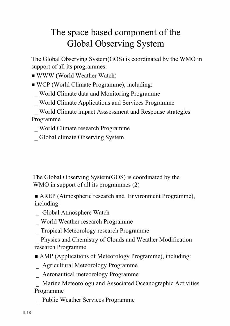
The space based component of the Global Observing System
The Global Observing System(GOS) is coordinated by the WMO in support of all its programmes:
WWW (World Weather Watch)WCP (World Climate Programme), including:
_ World Climate data and Monitoring Programme_ World Climate Applications and Services Programme_ World Climate impact Asssessment and Response strategies
Programme_ World Climate research Programme_ Global climate Observing System
AREP (Atmospheric research and Environment Programme), including:_ Global Atmosphere Watch_ World Weather research Programme_ Tropical Meteorology research Programme_ Physics and Chemistry of Clouds and Weather Modification research Programme
AMP (Applications of Meteorology Programme), including:_ Agricultural Meteorology Programme_ Aeronautical meteorology Programme_ Marine Meteorologu and Associated Oceanographic Activities Programme_ Public Weather Services Programme
The Global Observing System(GOS) is coordinated by the WMO in support of all its programmes (2)
III.18
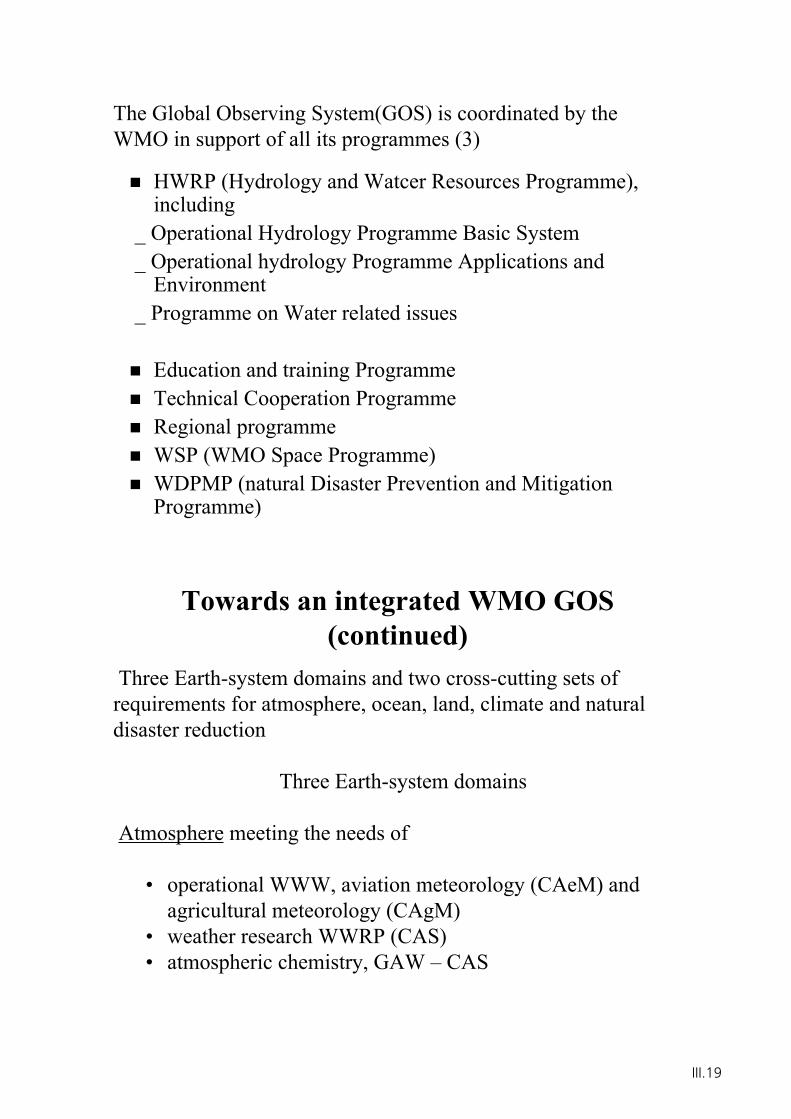
HWRP (Hydrology and Watcer Resources Programme), including
_ Operational Hydrology Programme Basic System_ Operational hydrology Programme Applications and
Environment_ Programme on Water related issues
Education and training ProgrammeTechnical Cooperation ProgrammeRegional programmeWSP (WMO Space Programme)WDPMP (natural Disaster Prevention and Mitigation Programme)
The Global Observing System(GOS) is coordinated by the WMO in support of all its programmes (3)
Towards an integrated WMO GOS (continued)
Three Earth-system domains and two cross-cutting sets of requirements for atmosphere, ocean, land, climate and natural disaster reduction
Three Earth-system domains
Atmosphere meeting the needs of
• operational WWW, aviation meteorology (CAeM) and agricultural meteorology (CAgM)
• weather research WWRP (CAS)• atmospheric chemistry, GAW – CAS
III.19
Towards an integrated WMO GOS (continued)
Three Earth-system domains (continued)
Ocean meeting the needs of
• Global Ocean Observing System (GOOS) • JCOMM
Towards an integrated WMO GOS (continued)
Three Earth-system domains (continued)
Land surface and fresh water meeting the needs of
• World Hydrological Cycle Observing System (WHyCOS)• Hydrology and Water Resource Programme (HWR) as
articulated through CHy• WMO-co-sponsored Global terrestrial Observing System
(GTOS)• CAgM
III.20
Towards an integrated WMO GOS (continued)
Two cross-cutting sets of requirements
Climate, incremental to, and integrating across, the domain-based observing systems meeting the needs of
• climate research, (WCRP)• climate policy, articulated through SBSTA, COP, based on information from IPCC etc.• climate monitoring and services, articulated through CCl, CAgM, CHy
Natural disaster reduction, incremental to, and integrating across, the domain-based observing systems to support WMO Natural Disaster Prevention and Mitigation Programme
Towards an integrated WMO GOS
Space-based sub-system of an integrated WMO global observing system
• operational meteorological polar orbiting satellites• operational meteorological geostationary satellites• environmental Research and Development satellite
constellations
III.21
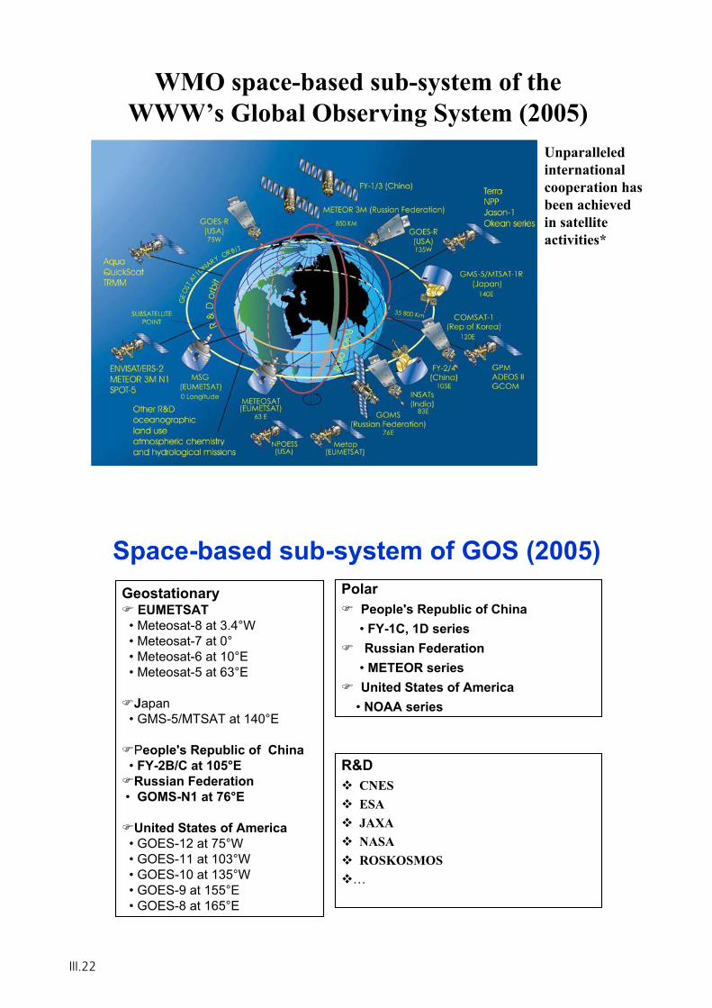
WMO space-based sub-system of the WWW’s Global Observing System (2005)
Unparalleledinternationalcooperation has been achieved in satellite activities*
Space-based sub-system of GOS (2005)Geostationary
EUMETSAT• Meteosat-8 at 3.4°W• Meteosat-7 at 0°• Meteosat-6 at 10°E• Meteosat-5 at 63°E
Japan• GMS-5/MTSAT at 140°E
People's Republic of China • FY-2B/C at 105°ERussian Federation
• GOMS-N1 at 76°E
United States of America• GOES-12 at 75°W• GOES-11 at 103°W• GOES-10 at 135°W• GOES-9 at 155°E• GOES-8 at 165°E
PolarPeople's Republic of China• FY-1C, 1D seriesRussian Federation
• METEOR seriesUnited States of America
• NOAA series
R&DCNESESAJAXANASAROSKOSMOS
…
III.22
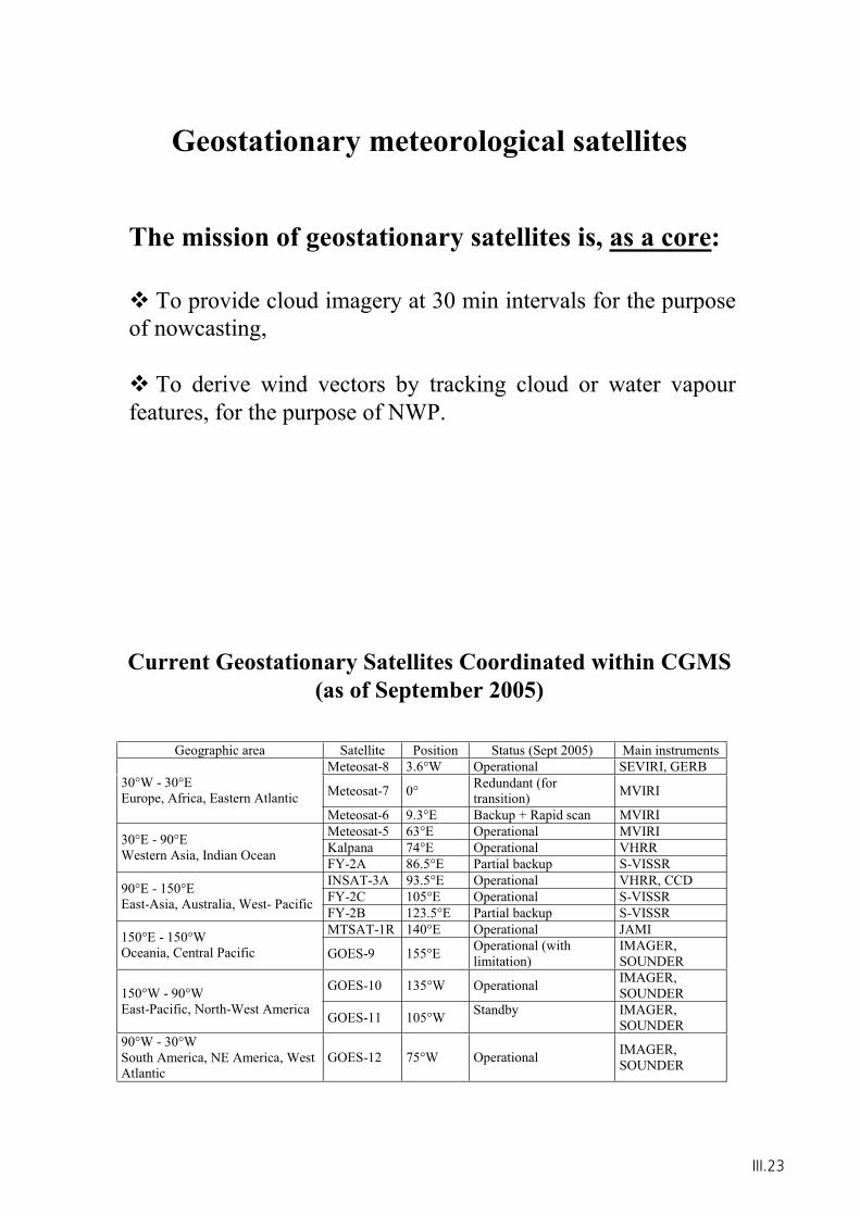
Geostationary meteorological satellites
The mission of geostationary satellites is, as a core:
To provide cloud imagery at 30 min intervals for the purpose of nowcasting,
To derive wind vectors by tracking cloud or water vapour features, for the purpose of NWP.
Current Geostationary Satellites Coordinated within CGMS(as of September 2005)
Geographic area Satellite Position Status (Sept 2005) Main instruments Meteosat-8 3.6°W Operational SEVIRI, GERB
Meteosat-7 0° Redundant (for transition) MVIRI 30°W - 30°E
Europe, Africa, Eastern Atlantic Meteosat-6 9.3°E Backup + Rapid scan MVIRI Meteosat-5 63°E Operational MVIRI Kalpana 74°E Operational VHRR 30°E - 90°E
Western Asia, Indian Ocean FY-2A 86.5°E Partial backup S-VISSR INSAT-3A 93.5°E Operational VHRR, CCD FY-2C 105°E Operational S-VISSR 90°E - 150°E
East-Asia, Australia, West- Pacific FY-2B 123.5°E Partial backup S-VISSR MTSAT-1R 140°E Operational JAMI 150°E - 150°W
Oceania, Central Pacific GOES-9 155°E Operational (with limitation)
IMAGER, SOUNDER
GOES-10 135°W Operational IMAGER, SOUNDER150°W - 90°W
East-Pacific, North-West America GOES-11 105°W Standby IMAGER, SOUNDER
90°W - 30°W South America, NE America, West Atlantic
GOES-12 75°W Operational IMAGER, SOUNDER
III.23
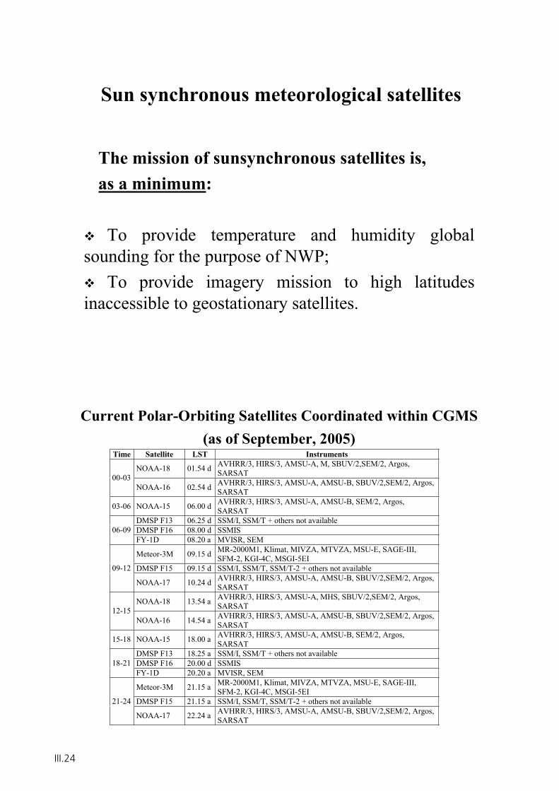
Sun synchronous meteorological satellites
The mission of sunsynchronous satellites is, as a minimum:
To provide temperature and humidity global sounding for the purpose of NWP;
To provide imagery mission to high latitudes inaccessible to geostationary satellites.
Current Polar-Orbiting Satellites Coordinated within CGMS(as of September, 2005)
Time Satellite LST Instruments
NOAA-18 01.54 d AVHRR/3, HIRS/3, AMSU-A, M, SBUV/2,SEM/2, Argos,SARSAT00-03
NOAA-16 02.54 d AVHRR/3, HIRS/3, AMSU-A, AMSU-B, SBUV/2,SEM/2, Argos,SARSAT
03-06 NOAA-15 06.00 d AVHRR/3, HIRS/3, AMSU-A, AMSU-B, SEM/2, Argos,SARSAT
DMSP F13 06.25 d SSM/I, SSM/T + others not availableDMSP F16 08.00 d SSMIS06-09FY-1D 08.20 a MVISR, SEM
Meteor-3M 09.15 d MR-2000M1, Klimat, MIVZA, MTVZA, MSU-E, SAGE-III,SFM-2, KGI-4C, MSGI-5EI
DMSP F15 09.15 d SSM/I, SSM/T, SSM/T-2 + others not available09-12
NOAA-17 10.24 d AVHRR/3, HIRS/3, AMSU-A, AMSU-B, SBUV/2,SEM/2, Argos,SARSAT
NOAA-18 13.54 a AVHRR/3, HIRS/3, AMSU-A, MHS, SBUV/2,SEM/2, Argos,SARSAT12-15
NOAA-16 14.54 a AVHRR/3, HIRS/3, AMSU-A, AMSU-B, SBUV/2,SEM/2, Argos,SARSAT
15-18 NOAA-15 18.00 a AVHRR/3, HIRS/3, AMSU-A, AMSU-B, SEM/2, Argos,SARSAT
DMSP F13 18.25 a SSM/I, SSM/T + others not availableDMSP F16 20.00 d SSMIS18-21FY-1D 20.20 a MVISR, SEM
Meteor-3M 21.15 a MR-2000M1, Klimat, MIVZA, MTVZA, MSU-E, SAGE-III,SFM-2, KGI-4C, MSGI-5EI
DMSP F15 21.15 a SSM/I, SSM/T, SSM/T-2 + others not available21-24
NOAA-17 22.24 a AVHRR/3, HIRS/3, AMSU-A, AMSU-B, SBUV/2,SEM/2, Argos,SARSAT
III.24
R&D programmes of GOS interest
ESA programmes have three activity lines:
Earth Watch programmes, inclusive of their predecessor realisations;the ERS-1 / ERS-2 / Envisat programmes ;
the Earth Explorer programme.
R&D programmes of GOS interest
NASA programmes
the Nimbus programme, SeaSat, ERBS, UARS; the Landsat programme; the EOS programme;the Earth System Science Pathfinder programme; a selection of other missions relevant for GOS.
III.25
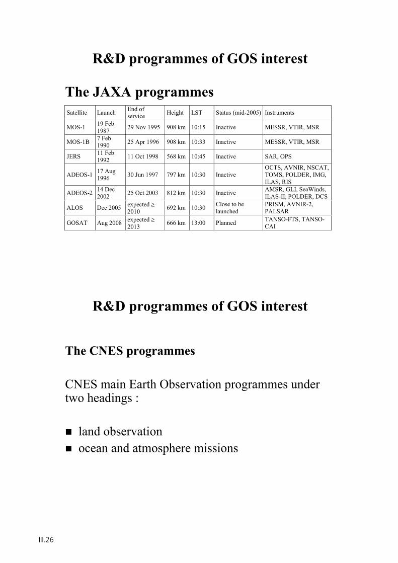
R&D programmes of GOS interest
The JAXA programmesSatellite Launch End of
service Height LST Status (mid-2005) Instruments
MOS-1 19 Feb 1987 29 Nov 1995 908 km 10:15 Inactive MESSR, VTIR, MSR
MOS-1B 7 Feb 1990 25 Apr 1996 908 km 10:33 Inactive MESSR, VTIR, MSR
JERS 11 Feb 1992 11 Oct 1998 568 km 10:45 Inactive SAR, OPS
ADEOS-1 17 Aug 1996 30 Jun 1997 797 km 10:30 Inactive
OCTS, AVNIR, NSCAT, TOMS, POLDER, IMG, ILAS, RIS
ADEOS-2 14 Dec 2002 25 Oct 2003 812 km 10:30 Inactive AMSR, GLI, SeaWinds,
ILAS-II, POLDER, DCS
ALOS Dec 2005 expected 2010 692 km 10:30 Close to be
launchedPRISM, AVNIR-2, PALSAR
GOSAT Aug 2008 expected 2013 666 km 13:00 Planned TANSO-FTS, TANSO-
CAI
R&D programmes of GOS interest
The CNES programmes
CNES main Earth Observation programmes under two headings :
land observation ocean and atmosphere missions
III.26
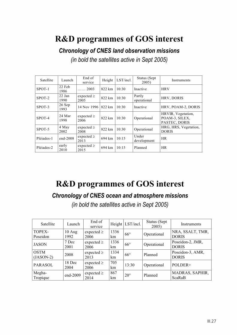
R&D programmes of GOS interestChronology of CNES land observation missions
(in bold the satellites active in Sept 2005)
Satellite Launch End of service Height LST/incl. Status (Sept
2005) Instruments
SPOT-1 22 Feb 1986 …… 2003 822 km 10:30 Inactive HRV
SPOT-2 22 Jan 1990
expected 2005 822 km 10:30 Partly
operational HRV, DORIS
SPOT-3 26 Sep 1993 14 Nov 1996 822 km 10:30 Inactive HRV, POAM-2, DORIS
SPOT-4 24 Mar 1998
expected 2006 822 km 10:30 Operational
HRVIR, Vegetation, POAM-3, SILEX, PASTEC, DORIS
SPOT-5 4 May 2002
expected 2008 822 km 10:30 Operational HRG, HRS, Vegetation,
DORIS
Pléiades-1 end-2008 expected 2013 694 km 10:15 Under
development HR
Pléiades-2 early 2010
expected 2015 694 km 10:15 Planned HR
R&D programmes of GOS interestChronology of CNES ocean and atmosphere missions
(in bold the satellites active in Sept 2005)
Satellite Launch End of service Height LST/incl. Status (Sept
2005) Instruments
TOPEX-Poseidon
10 Aug 1992
expected 2006
1336km 66° Operational NRA, SSALT, TMR,
DORIS
JASON 7 Dec 2001
expected 2006
1336km 66° Operational Poseidon-2, JMR,
DORIS OSTM(JASON-2) 2008 expected
20131334km 66° Planned Poseidon-3, AMR,
DORIS
PARASOL 18 Dec 2004
expected 2006
705km 13:30 Operational POLDER+
Megha-Tropique end-2009 expected
2014867km 20° Planned MADRAS, SAPHIR,
ScaRaB
III.27
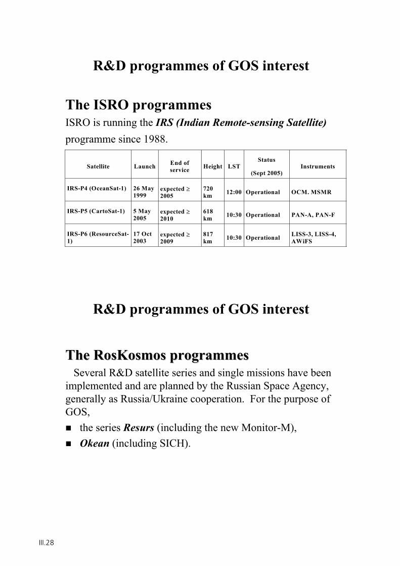
R&D programmes of GOS interest
The ISRO programmesISRO is running the IRS (Indian Remote-sensing Satellite)programme since 1988.
Satellite Launch End of service Height LST
Status
(Sept 2005) Instruments
IRS-P4 (OceanSat-1) 26 May 1999
expected 2005
720km 12:00 Operational OCM. MSMR
IRS-P5 (CartoSat-1) 5 May 2005
expected 2010
618km 10:30 Operational PAN-A, PAN-F
IRS-P6 (ResourceSat-1)
17 Oct 2003
expected 2009
817km 10:30 Operational LISS-3, LISS-4,
AWiFS
R&D programmes of GOS interest
TheThe RosKosmosRosKosmos programmesprogrammesSeveral R&D satellite series and single missions have been
implemented and are planned by the Russian Space Agency, generally as Russia/Ukraine cooperation. For the purpose of GOS,
the series Resurs (including the new Monitor-M), Okean (including SICH).
III.28
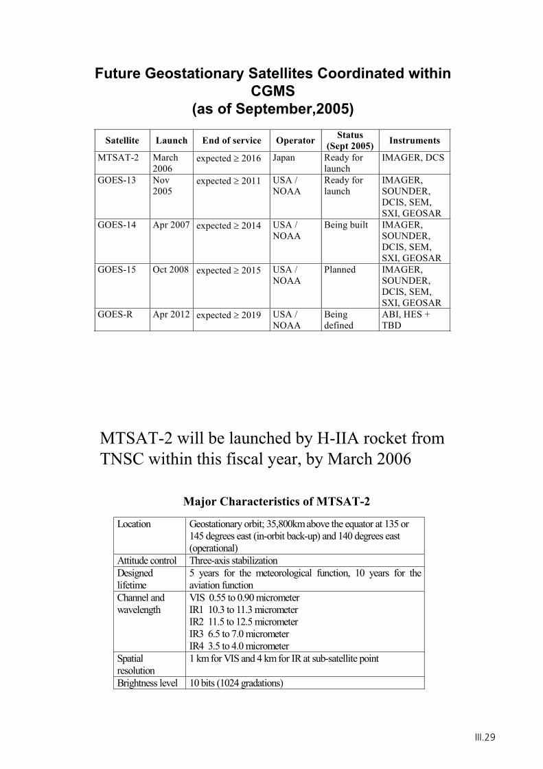
Future Geostationary Satellites Coordinated within CGMS
(as of September,2005)
Satellite Launch End of service Operator Status (Sept 2005) Instruments
MTSAT-2 March 2006
expected 2016 Japan Ready for launch
IMAGER, DCS
GOES-13 Nov 2005
expected 2011 USA / NOAA
Ready for launch
IMAGER, SOUNDER, DCIS, SEM, SXI, GEOSAR
GOES-14 Apr 2007 expected 2014 USA / NOAA
Being built IMAGER, SOUNDER, DCIS, SEM, SXI, GEOSAR
GOES-15 Oct 2008 expected 2015 USA / NOAA
Planned IMAGER, SOUNDER, DCIS, SEM, SXI, GEOSAR
GOES-R Apr 2012 expected 2019 USA / NOAA
Being defined
ABI, HES + TBD
Location Geostationary orbit; 35,800km above the equator at 135 or 145 degrees east (in-orbit back-up) and 140 degrees east (operational)
Attitude control Three-axis stabilization Designed lifetime
5 years for the meteorological function, 10 years for the aviation function
Channel and wavelength
VIS 0.55 to 0.90 micrometer IR1 10.3 to 11.3 micrometer IR2 11.5 to 12.5 micrometer IR3 6.5 to 7.0 micrometer IR4 3.5 to 4.0 micrometer
Spatial resolution
1 km for VIS and 4 km for IR at sub-satellite point
Brightness level 10 bits (1024 gradations)
Major Characteristics of MTSAT-2
MTSAT-2 will be launched by H-IIA rocket from TNSC within this fiscal year, by March 2006
III.29
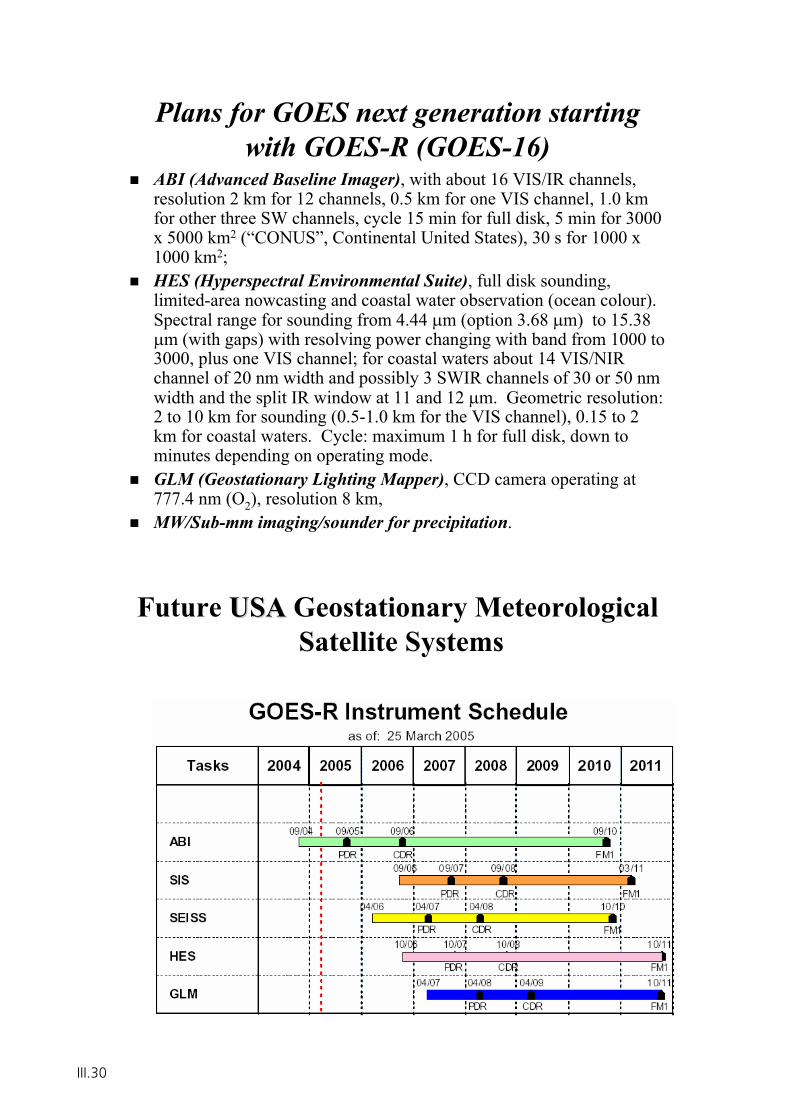
Plans for GOES next generation starting with GOES-R (GOES-16)
ABI (Advanced Baseline Imager), with about 16 VIS/IR channels, resolution 2 km for 12 channels, 0.5 km for one VIS channel, 1.0 km for other three SW channels, cycle 15 min for full disk, 5 min for 3000 x 5000 km2 (“CONUS”, Continental United States), 30 s for 1000 x 1000 km2;HES (Hyperspectral Environmental Suite), full disk sounding, limited-area nowcasting and coastal water observation (ocean colour). Spectral range for sounding from 4.44 m (option 3.68 m) to 15.38
m (with gaps) with resolving power changing with band from 1000 to 3000, plus one VIS channel; for coastal waters about 14 VIS/NIR channel of 20 nm width and possibly 3 SWIR channels of 30 or 50 nm width and the split IR window at 11 and 12 m. Geometric resolution: 2 to 10 km for sounding (0.5-1.0 km for the VIS channel), 0.15 to 2 km for coastal waters. Cycle: maximum 1 h for full disk, down to minutes depending on operating mode. GLM (Geostationary Lighting Mapper), CCD camera operating at 777.4 nm (O2), resolution 8 km, MW/Sub-mm imaging/sounder for precipitation.
Future USAUSA Geostationary MeteorologicalSatellite Systems
III.30
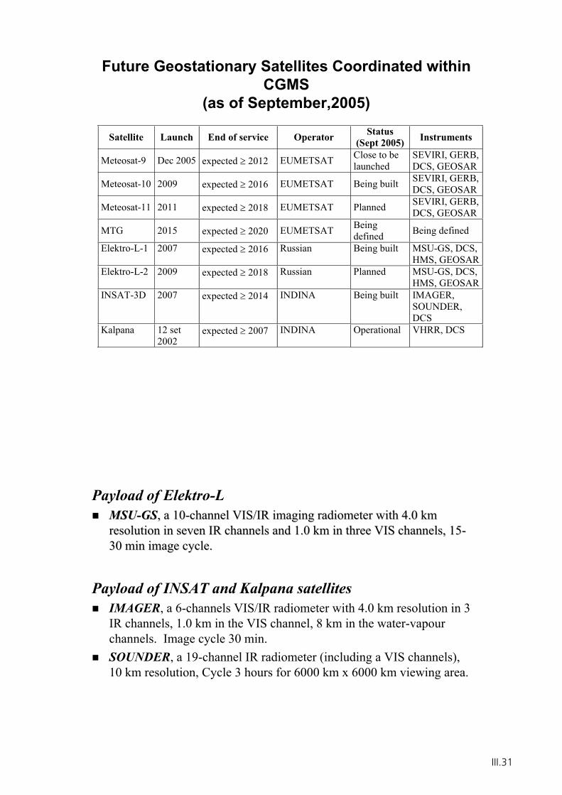
Future Geostationary Satellites Coordinated within CGMS
(as of September,2005)
Satellite Launch End of service Operator Status(Sept 2005) Instruments
Meteosat-9 Dec 2005 expected 2012 EUMETSAT Close to be launched
SEVIRI, GERB, DCS, GEOSAR
Meteosat-10 2009 expected 2016 EUMETSAT Being built SEVIRI, GERB, DCS, GEOSAR
Meteosat-11 2011 expected 2018 EUMETSAT Planned SEVIRI, GERB, DCS, GEOSAR
MTG 2015 expected 2020 EUMETSAT Being defined Being defined
Elektro-L-1 2007 expected 2016 Russian Being built MSU-GS, DCS, HMS, GEOSAR
Elektro-L-2 2009 expected 2018 Russian Planned MSU-GS, DCS, HMS, GEOSAR
INSAT-3D 2007 expected 2014 INDINA Being built IMAGER, SOUNDER,DCS
Kalpana 12 set 2002
expected 2007 INDINA Operational VHRR, DCS
Payload of Elektro-LMSUMSU--GSGS, a 10, a 10--channel VIS/IR imaging radiometer with 4.0 km channel VIS/IR imaging radiometer with 4.0 km resolution in seven IR channels and 1.0 km in three VIS channelsresolution in seven IR channels and 1.0 km in three VIS channels, 15, 15--30 min image cycle. 30 min image cycle.
Payload of INSAT and Kalpana satellitesIMAGER, a 6-channels VIS/IR radiometer with 4.0 km resolution in 3 IR channels, 1.0 km in the VIS channel, 8 km in the water-vapour channels. Image cycle 30 min. SOUNDER, a 19-channel IR radiometer (including a VIS channels), 10 km resolution, Cycle 3 hours for 6000 km x 6000 km viewing area.
III.31
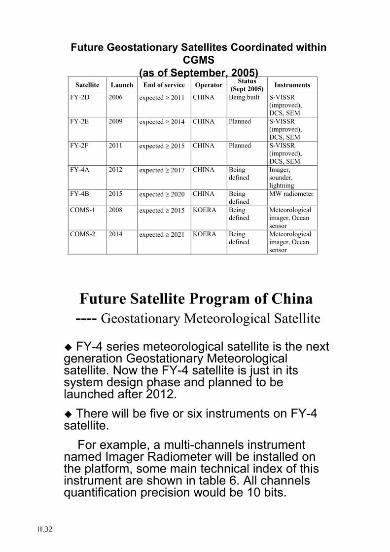
Future Geostationary Satellites Coordinated within CGMS
(as of September, 2005)Satellite Launch End of service Operator Status
(Sept 2005) Instruments
FY-2D 2006 expected 2011 CHINA Being built S-VISSR (improved), DCS, SEM
FY-2E 2009 expected 2014 CHINA Planned S-VISSR (improved), DCS, SEM
FY-2F 2011 expected 2015 CHINA Planned S-VISSR (improved), DCS, SEM
FY-4A 2012 expected 2017 CHINA Being defined
Imager, sounder, lightning
FY-4B 2015 expected 2020 CHINA Being defined
MW radiometer
COMS-1 2008 expected 2015 KOERA Being defined
Meteorological imager, Ocean sensor
COMS-2 2014 expected 2021 KOERA Being defined
Meteorological imager, Ocean sensor
Future Satellite Program of China---- Geostationary Meteorological Satellite
FY-4 series meteorological satellite is the next generation Geostationary Meteorological satellite. Now the FY-4 satellite is just in its system design phase and planned to be launched after 2012.
There will be five or six instruments on FY-4 satellite.
For example, a multi-channels instrument named Imager Radiometer will be installed on the platform, some main technical index of this instrument are shown in table 6. All channels quantification precision would be 10 bits.
III.32
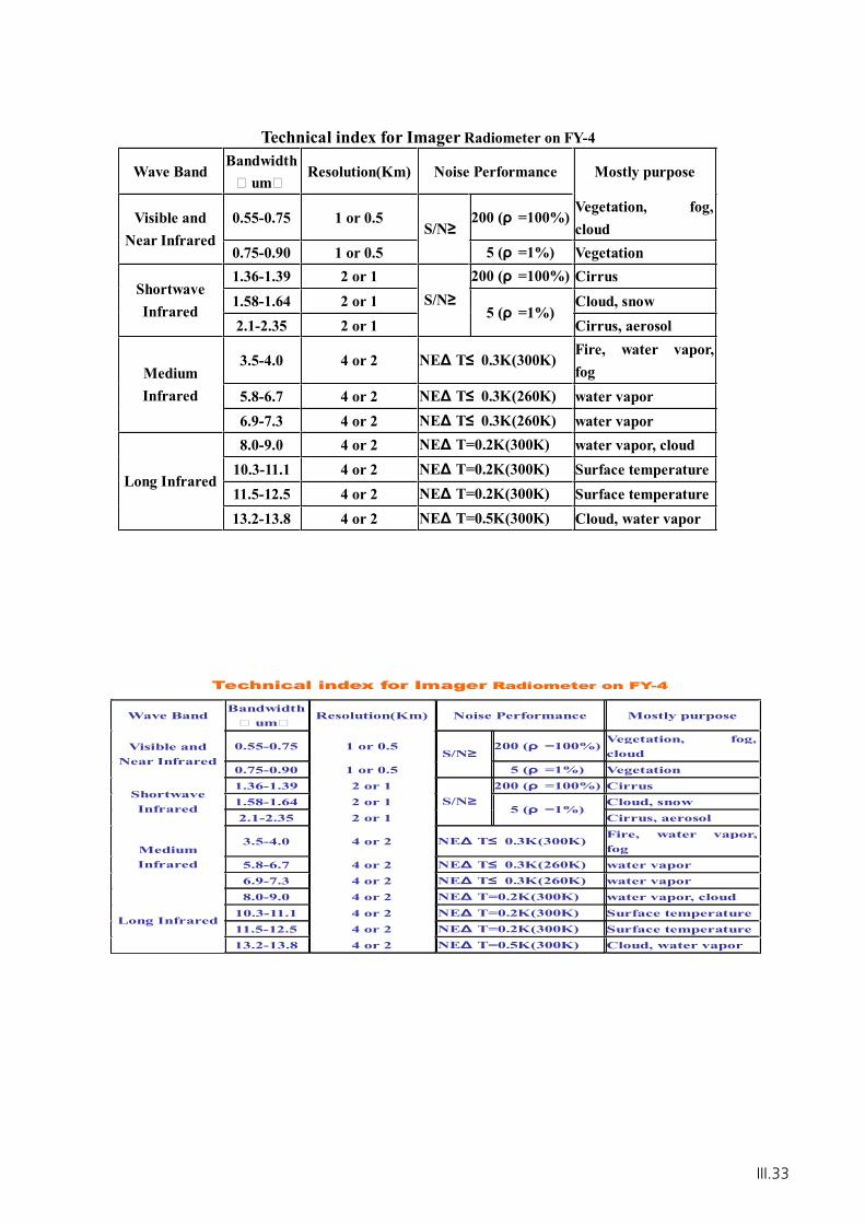
Technical index for Imager Radiometer on FY-4
Wave BandBandwidth
� um�Resolution(Km) Noise Performance Mostly purpose
0.55-0.75 1 or 0.5 200 ( =100%)Vegetation, fog,cloud
Visible andNear Infrared
0.75-0.90 1 or 0.5 S/N
5 ( =1%) Vegetation1.36-1.39 2 or 1 200 ( =100%) Cirrus1.58-1.64 2 or 1 Cloud, snow
ShortwaveInfrared
2.1-2.35 2 or 1
S/N 5 ( =1%)
Cirrus, aerosol
3.5-4.0 4 or 2 NE T 0.3K(300K)Fire, water vapor,fog
5.8-6.7 4 or 2 NE T 0.3K(260K) water vaporMediumInfrared
6.9-7.3 4 or 2 NE T 0.3K(260K) water vapor8.0-9.0 4 or 2 NE T=0.2K(300K) water vapor, cloud
10.3-11.1 4 or 2 NE T=0.2K(300K) Surface temperature11.5-12.5 4 or 2 NE T=0.2K(300K) Surface temperature
Long Infrared
13.2-13.8 4 or 2 NE T=0.5K(300K) Cloud, water vapor
III.33
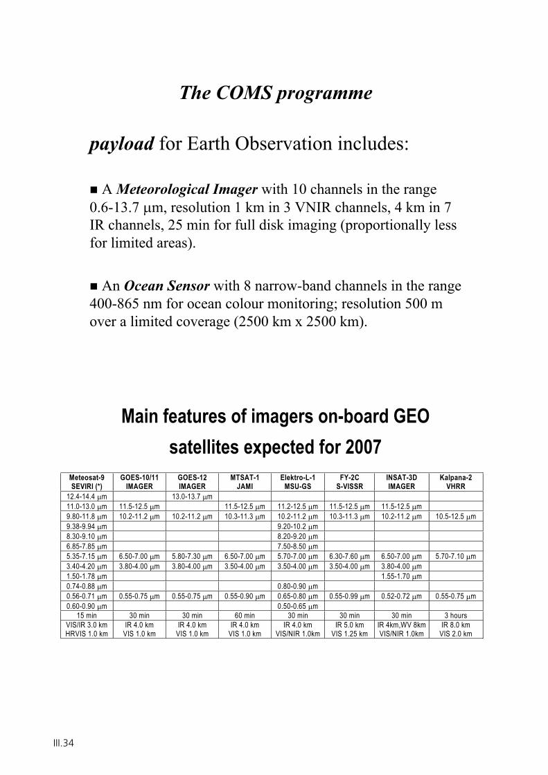
The COMS programme
payload for Earth Observation includes:
A Meteorological Imager with 10 channels in the range 0.6-13.7 m, resolution 1 km in 3 VNIR channels, 4 km in 7 IR channels, 25 min for full disk imaging (proportionally less for limited areas).
An Ocean Sensor with 8 narrow-band channels in the range400-865 nm for ocean colour monitoring; resolution 500 m over a limited coverage (2500 km x 2500 km).
Main features of imagers on-board GEO satellites expected for 2007
Meteosat-9 SEVIRI (*)
GOES-10/11 IMAGER
GOES-12 IMAGER
MTSAT-1 JAMI
Elektro-L-1 MSU-GS
FY-2C S-VISSR
INSAT-3D IMAGER
Kalpana-2 VHRR
12.4-14.4 m 13.0-13.7 m 11.0-13.0 m 11.5-12.5 m 11.5-12.5 m 11.2-12.5 m 11.5-12.5 m 11.5-12.5 m9.80-11.8 m 10.2-11.2 m 10.2-11.2 m 10.3-11.3 m 10.2-11.2 m 10.3-11.3 m 10.2-11.2 m 10.5-12.5 m9.38-9.94 m 9.20-10.2 m 8.30-9.10 m 8.20-9.20 m 6.85-7.85 m 7.50-8.50 m 5.35-7.15 m 6.50-7.00 m 5.80-7.30 m 6.50-7.00 m 5.70-7.00 m 6.30-7.60 m 6.50-7.00 m 5.70-7.10 m3.40-4.20 m 3.80-4.00 m 3.80-4.00 m 3.50-4.00 m 3.50-4.00 m 3.50-4.00 m 3.80-4.00 m1.50-1.78 m 1.55-1.70 m0.74-0.88 m 0.80-0.90 m 0.56-0.71 m 0.55-0.75 m 0.55-0.75 m 0.55-0.90 m 0.65-0.80 m 0.55-0.99 m 0.52-0.72 m 0.55-0.75 m0.60-0.90 m 0.50-0.65 m
15 min 30 min 30 min 60 min 30 min 30 min 30 min 3 hours VIS/IR 3.0 km HRVIS 1.0 km
IR 4.0 km VIS 1.0 km
IR 4.0 km VIS 1.0 km
IR 4.0 km VIS 1.0 km
IR 4.0 km VIS/NIR 1.0km
IR 5.0 km VIS 1.25 km
IR 4km,WV 8kmVIS/NIR 1.0km
IR 8.0 km VIS 2.0 km
III.34
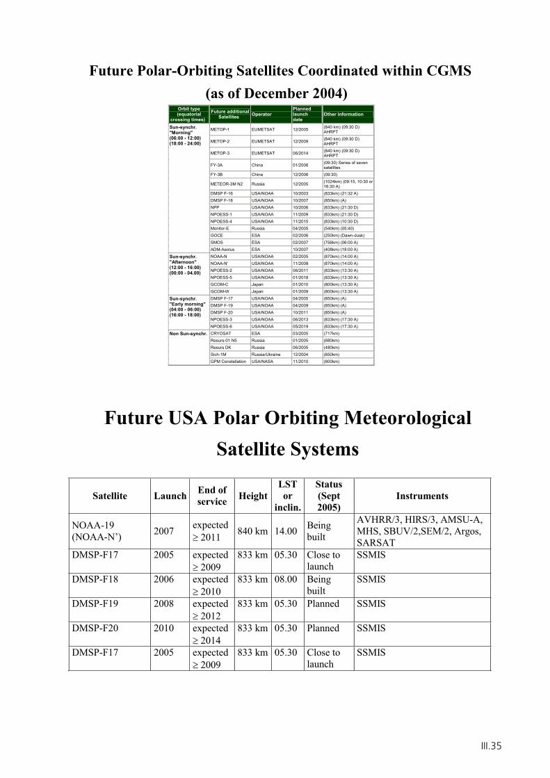
Future Polar-Orbiting Satellites Coordinated within CGMS(as of December 2004)
Orbit type (equatorial
crossing times) Future additional
Satellites Operator Planned launch date
Other information
METOP-1 EUMETSAT 12/2005 (840 km) (09:30 D) AHRPT
METOP-2 EUMETSAT 12/2009 (840 km) (09:30 D) AHRPT
METOP-3 EUMETSAT 06/2014 (840 km) (09:30 D) AHRPT
FY-3A China 01/2006 (09:30) Series of seven satellites
FY-3B China 12/2006 (09:30)
METEOR-3M N2 Russia 12/2005 (1024km) (09:15, 10:30 or 16:30 A)
DMSP F-16 USA/NOAA 10/2003 (833km) (21:32 A)DMSP F-18 USA/NOAA 10/2007 (850km) (A)NPP USA/NOAA 10/2006 (833km) (21:30 D)NPOESS-1 USA/NOAA 11/2009 (833km) (21:30 D)NPOESS-4 USA/NOAA 11/2015 (833km) (10:30 D)Monitor-E Russia 04/2005 (540km) (05:40)GOCE ESA 02/2006 (250km) (Dawn-dusk)SMOS ESA 02/2007 (756km) (06:00 A)
Sun-synchr. "Morning" (06:00 - 12:00)(18:00 - 24:00)
ADM-Aeolus ESA 10/2007 (408km) (18:00 A)NOAA-N USA/NOAA 02/2005 (870km) (14:00 A)NOAA-N' USA/NOAA 11/2008 (870km) (14:00 A)NPOESS-2 USA/NOAA 06/2011 (833km) (13:30 A)NPOESS-5 USA/NOAA 01/2018 (833km) (13:30 A)GCOM-C Japan 01/2010 (800km) (13:30 A)
Sun-synchr. "Afternoon" (12:00 - 16:00)(00:00 - 04.00)
GCOM-W Japan 01/2009 (800km) (13:30 A)DMSP F-17 USA/NOAA 04/2005 (850km) (A)DMSP F-19 USA/NOAA 04/2009 (850km) (A)DMSP F-20 USA/NOAA 10/2011 (850km) (A)NPOESS-3 USA/NOAA 06/2013 (833km) (17:30 A)
Sun-synchr. "Early morning"(04:00 - 06:00)(16:00 - 18:00)
NPOESS-6 USA/NOAA 05/2019 (833km) (17:30 A)CRYOSAT ESA 03/2005 (717km)Resurs-01 N5 Russia 01/2005 (680km)Resurs DK Russia 06/2005 (480km)Sich-1M Russia/Ukraine 12/2004 (650km)
Non Sun-synchr.
GPM Constellation USA/NASA 11/2010 (600km)
Future USA Polar Orbiting Meteorological Satellite Systems
Satellite Launch End of service Height
LSTor
inclin.
Status(Sept2005)
Instruments
NOAA-19(NOAA-N’) 2007 expected
2011 840 km 14.00 Being built
AVHRR/3, HIRS/3, AMSU-A, MHS, SBUV/2,SEM/2, Argos, SARSAT
DMSP-F17 2005 expected 2009
833 km 05.30 Close to launch
SSMIS
DMSP-F18 2006 expected 2010
833 km 08.00 Being built
SSMIS
DMSP-F19 2008 expected 2012
833 km 05.30 Planned SSMIS
DMSP-F20 2010 expected 2014
833 km 05.30 Planned SSMIS
DMSP-F17 2005 expected 2009
833 km 05.30 Close to launch
SSMIS
III.35
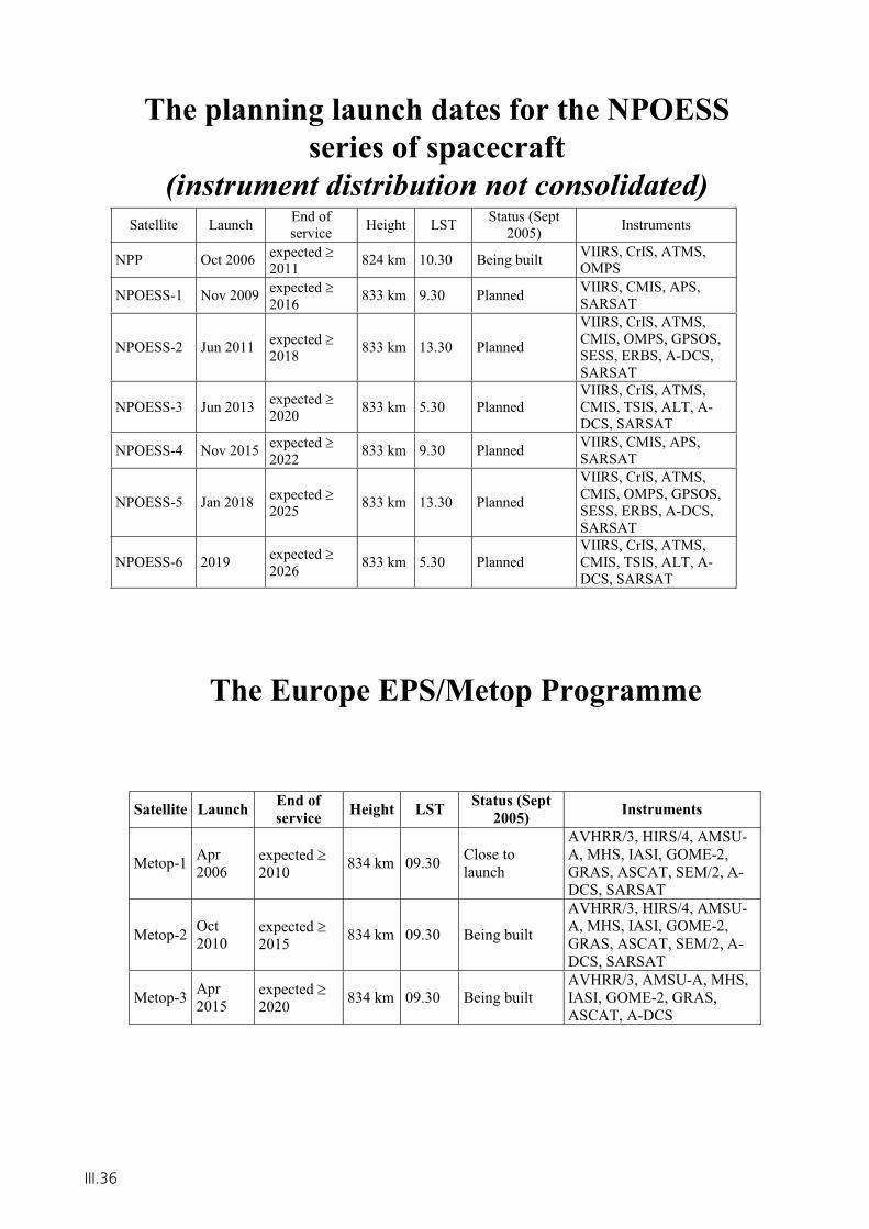
The planning launch dates for the NPOESS series of spacecraft
(instrument distribution not consolidated)Satellite Launch End of
service Height LST Status (Sept 2005) Instruments
NPP Oct 2006 expected 2011 824 km 10.30 Being built VIIRS, CrIS, ATMS,
OMPS
NPOESS-1 Nov 2009 expected 2016 833 km 9.30 Planned VIIRS, CMIS, APS,
SARSAT
NPOESS-2 Jun 2011 expected 2018 833 km 13.30 Planned
VIIRS, CrIS, ATMS, CMIS, OMPS, GPSOS, SESS, ERBS, A-DCS, SARSAT
NPOESS-3 Jun 2013 expected 2020 833 km 5.30 Planned
VIIRS, CrIS, ATMS, CMIS, TSIS, ALT, A-DCS, SARSAT
NPOESS-4 Nov 2015 expected 2022 833 km 9.30 Planned VIIRS, CMIS, APS,
SARSAT
NPOESS-5 Jan 2018 expected 2025 833 km 13.30 Planned
VIIRS, CrIS, ATMS, CMIS, OMPS, GPSOS, SESS, ERBS, A-DCS, SARSAT
NPOESS-6 2019 expected 2026 833 km 5.30 Planned
VIIRS, CrIS, ATMS, CMIS, TSIS, ALT, A-DCS, SARSAT
The Europe EPS/Metop Programme
Satellite Launch End of service Height LST Status (Sept
2005) Instruments
Metop-1 Apr2006
expected 2010 834 km 09.30 Close to
launch
AVHRR/3, HIRS/4, AMSU-A, MHS, IASI, GOME-2, GRAS, ASCAT, SEM/2, A-DCS, SARSAT
Metop-2 Oct2010
expected 2015 834 km 09.30 Being built
AVHRR/3, HIRS/4, AMSU-A, MHS, IASI, GOME-2, GRAS, ASCAT, SEM/2, A-DCS, SARSAT
Metop-3 Apr2015
expected 2020 834 km 09.30 Being built
AVHRR/3, AMSU-A, MHS, IASI, GOME-2, GRAS, ASCAT, A-DCS
III.36
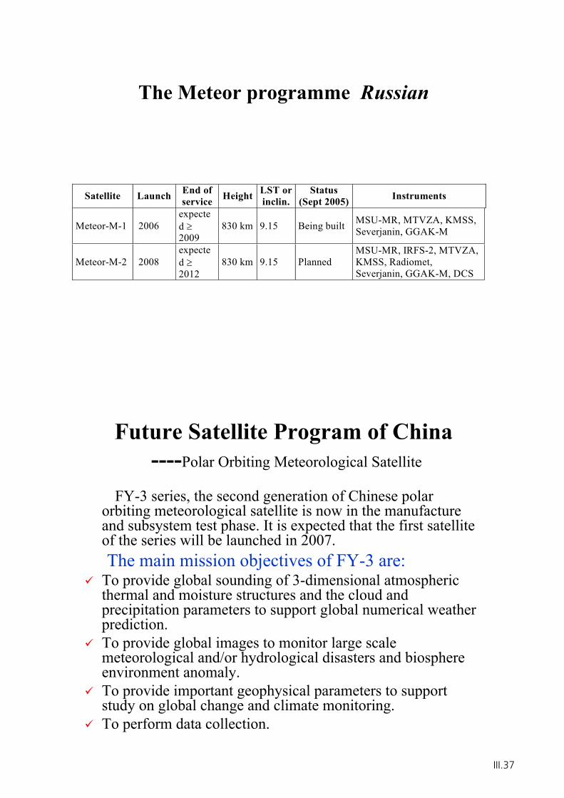
The Meteor programme Russian
Satellite Launch End of service Height LST or
inclin. Status
(Sept 2005) Instruments
Meteor-M-1 2006 expected2009
830 km 9.15 Being built MSU-MR, MTVZA, KMSS, Severjanin, GGAK-M
Meteor-M-2 2008 expected2012
830 km 9.15 Planned MSU-MR, IRFS-2, MTVZA, KMSS, Radiomet, Severjanin, GGAK-M, DCS
Future Satellite Program of China----Polar Orbiting Meteorological Satellite
FY-3 series, the second generation of Chinese polar orbiting meteorological satellite is now in the manufacture and subsystem test phase. It is expected that the first satellite of the series will be launched in 2007. The main mission objectives of FY-3 are:
To provide global sounding of 3-dimensional atmospheric thermal and moisture structures and the cloud and precipitation parameters to support global numerical weather prediction.To provide global images to monitor large scale meteorological and/or hydrological disasters and biosphere environment anomaly.To provide important geophysical parameters to support study on global change and climate monitoring.To perform data collection.
III.37
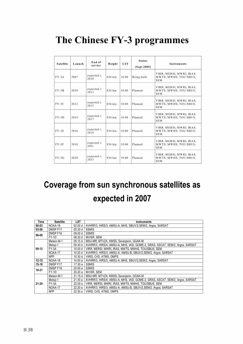
The Chinese FY-3 programmes
Satellite Launch End of service H eight LST
Status
(Sept 2005) Instruments
FY-3A 2007 expected 2010 836 km 10.00 Being built
VIRR, M ERSI, M W RI, IRAS, M W TS, M W HS, TOU/SBUS, SEM
FY-3B 2010 expected 2013 836 km 10.00 Planned
VIRR, M ERSI, M W RI, IRAS, M W TS, M W HS, TOU/SBUS, SEM
FY-3C 2012 expected 2015 836 km 10.00 Planned
VIRR, M ERSI, M W RI, IRAS, M W TS, M W HS, TOU/SBUS, SEM
FY-3D 2014 expected 2017 836 km 10.00 Planned
VIRR, M ERSI, M W RI, IRAS, M W TS, M W HS, TOU/SBUS, SEM
FY-3E 2016 expected 2019 836 km 10.00 Planned
VIRR, M ERSI, M W RI, IRAS, M W TS, M W HS, TOU/SBUS, SEM
FY-3F 2018 expected 2021 836 km 10.00 Planned
VIRR, M ERSI, M W RI, IRAS, M W TS, M W HS, TOU/SBUS, SEM
FY-3G 2020 expected 2023 836 km 10.00 Planned
VIRR, M ERSI, M W RI, IRAS, M W TS, M W HS, TOU/SBUS, SEM
Coverage from sun synchronous satellites as expected in 2007
Time Satellite LST Instruments 00-03 NOAA-18 02.00 d AVHRR/3, HIRS/3, AMSU-A, MHS, SBUV/2,SEM/2, Argos, SARSAT 03-06 DMSP F17 05.30 d SSMIS
DMSP F16 08.00 d SSMIS 06-09 FY-1D 08.20 d MVISR, SEM Meteor-M-1 09.15 d MSU-MR, MTVZA, KMSS, Severjanin, GGAK-M Metop-1 09.30 d AVHRR/3, HIRS/4, AMSU-A, MHS, IASI, GOME-2, GRAS, ASCAT, SEM/2, Argos, SARSAT FY-3A 10.00 d VIRR, MERSI, MWRI, IRAS, MWTS, MWHS, TOU/SBUS, SEM NOAA-17 10.20 d AVHRR/3, HIRS/3, AMSU-A, AMSU-B, SBUV/2,SEM/2, Argos, SARSAT
09-12
NPP 10.30 d VIIRS, CrIS, ATMS, OMPS 12-15 NOAA-18 14.00 a AVHRR/3, HIRS/3, AMSU-A, MHS, SBUV/2,SEM/2, Argos, SARSAT 15-18 DMSP F17 17.30 a SSMIS
DMSP F16 20.00 a SSMIS 18-21 FY-1D 20.20 a MVISR, SEM Meteor-M-1 21.15 d MSU-MR, MTVZA, KMSS, Severjanin, GGAK-M Metop-1 21.30 a AVHRR/3, HIRS/4, AMSU-A, MHS, IASI, GOME-2, GRAS, ASCAT, SEM/2, Argos, SARSAT FY-3A 22.00 a VIRR, MERSI, MWRI, IRAS, MWTS, MWHS, TOU/SBUS, SEM NOAA-17 22.20 a AVHRR/3, HIRS/3, AMSU-A, AMSU-B, SBUV/2,SEM/2, Argos, SARSAT
21-24
NPP 22.30 a VIIRS, CrIS, ATMS, OMPS
III.38

WMO Space Programme Web Site
http://www.wmo.int/index-en.html
Goals, objectives and publicationsSatellite operator status reportsGlobal Observing System (GOS) status reportsOther satellite related organizationsOnline database informationAPT/WEFAX to LRPT/LRIT transitionOnline satellite imagery sitesWorking documents for Upcoming MeetingsEducation and Training Materials
III.39

III.40
Chapter IV
The Future European
Earth Observation Missions
GMES, MTG & Post-EPS

GMES Space Segment and Relevant Earth Explorer Missions
Prof. A. Ginati
ESA-ESTEC
IV.1

IV.2
© ESA 2003
A. Ginati, ESA
Das GMES-Weltraumsegment&
relevante Earth Explorer Missionen
DLR & DWD Nationaler Nutzerworkshop “Operationelle Satellitensysteme der Erdüberwachung”7-9 November 2005, Walberberg
Table of Content
ESAESA’’ss LiLivingving PlanetPlanet PrograProgrammemme
GMESGMES
Earth Watch/EUMETSATEarth Watch/EUMETSAT
Earth Observation Envelope ProgrammeEarth Observation Envelope Programme
IV.3
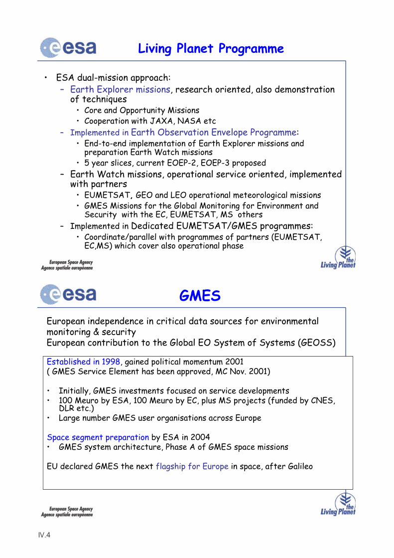
• ESA dual-mission approach:– Earth Explorer missions, research oriented, also demonstration
of techniques• Core and Opportunity Missions• Cooperation with JAXA, NASA etc
– Implemented in Earth Observation Envelope Programme:• End-to-end implementation of Earth Explorer missions and
preparation Earth Watch missions• 5 year slices, current EOEP-2, EOEP-3 proposed
– Earth Watch missions, operational service oriented, implemented with partners
• EUMETSAT, GEO and LEO operational meteorological missions• GMES Missions for the Global Monitoring for Environment and
Security with the EC, EUMETSAT, MS others– Implemented in Dedicated EUMETSAT/GMES programmes:
• Coordinate/parallel with programmes of partners (EUMETSAT, EC,MS) which cover also operational phase
Living Planet Programme
GMES
Established in 1998, gained political momentum 2001( GMES Service Element has been approved, MC Nov. 2001)
• Initially, GMES investments focused on service developments• 100 Meuro by ESA, 100 Meuro by EC, plus MS projects (funded by CNES,
DLR etc.)• Large number GMES user organisations across Europe
Space segment preparation by ESA in 2004 • GMES system architecture, Phase A of GMES space missions
EU declared GMES the next flagship for Europe in space, after Galileo
European independence in critical data sources for environmental monitoring & security European contribution to the Global EO System of Systems (GEOSS)
IV.4
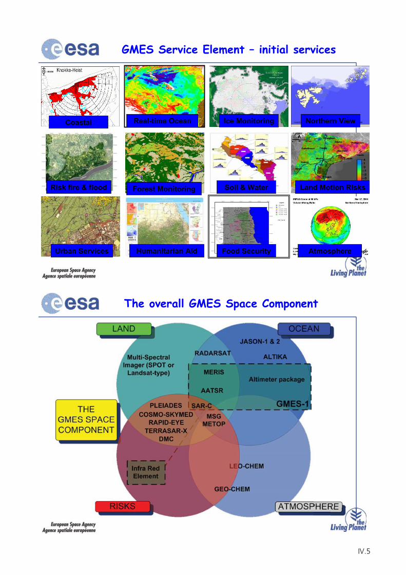
GMES Service Element – initial services
Coastal Real-time Ocean Ice Monitoring Northern View
Risk fire & flood Forest Monitoring Soil & Water Land Motion Risks
Urban Services Humanitarian Aid AtmosphereFood Security
The overall GMES Space Component
IV.5
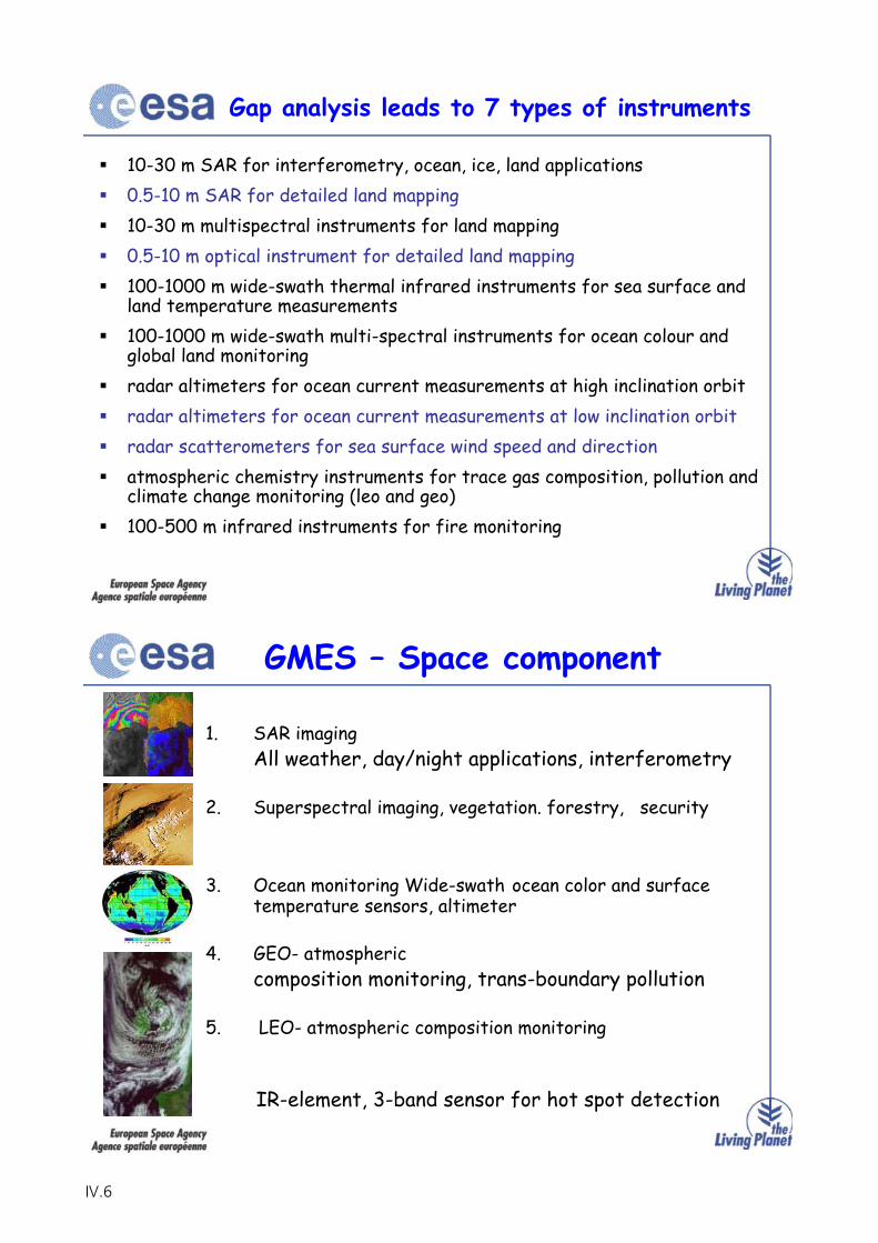
Gap analysis leads to 7 types of instruments
10-30 m SAR for interferometry, ocean, ice, land applications0.5-10 m SAR for detailed land mapping10-30 m multispectral instruments for land mapping0.5-10 m optical instrument for detailed land mapping100-1000 m wide-swath thermal infrared instruments for sea surface and land temperature measurements100-1000 m wide-swath multi-spectral instruments for ocean colour and global land monitoringradar altimeters for ocean current measurements at high inclination orbitradar altimeters for ocean current measurements at low inclination orbitradar scatterometers for sea surface wind speed and directionatmospheric chemistry instruments for trace gas composition, pollution and climate change monitoring (leo and geo)100-500 m infrared instruments for fire monitoring
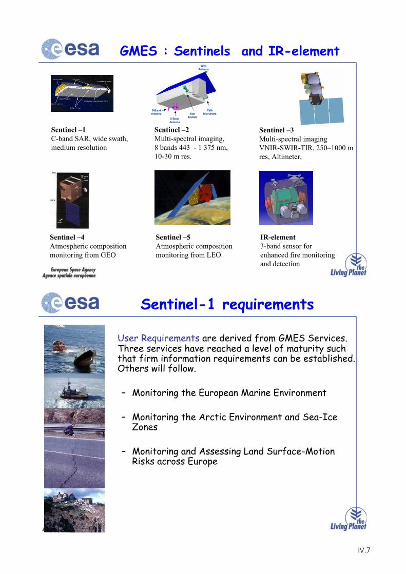
GMES – Space component
1. SAR imagingAll weather, day/night applications, interferometry
2. Superspectral imaging, vegetation. forestry, security
3. Ocean monitoring Wide-swath ocean color and surface temperature sensors, altimeter
4. GEO- atmosphericcomposition monitoring, trans-boundary pollution
5. LEO- atmospheric composition monitoring
IR-element, 3-band sensor for hot spot detection
IV.6
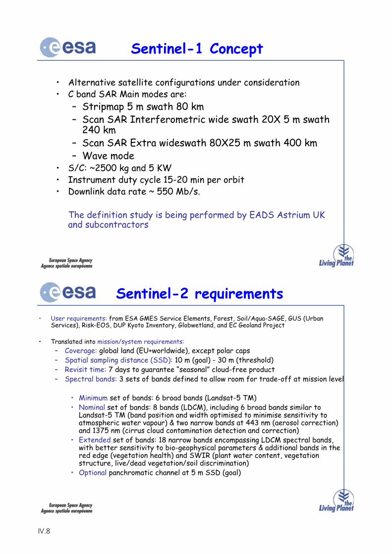
GMES : Sentinels and IR-element
TMAInstrumentStar
TrackerX-BandAntenna
GPSAntenna
S-BandAntenna
Sentinel –1 C-band SAR, wide swath, medium resolution
Sentinel –2 Multi-spectral imaging, 8 bands 443 - 1 375 nm, 10-30 m res.
Sentinel –3 Multi-spectral imaging VNIR-SWIR-TIR, 250–1000 m res, Altimeter,
Sentinel –4Atmospheric composition monitoring from GEO
Sentinel –5Atmospheric composition monitoring from LEO
IR-element3-band sensor for enhanced fire monitoring and detection
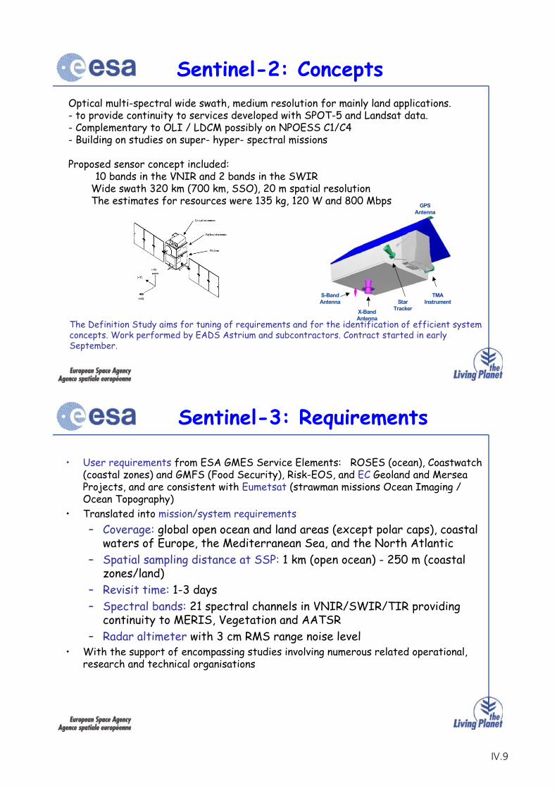
User Requirements are derived from GMES Services. Three services have reached a level of maturity such that firm information requirements can be established. Others will follow.
– Monitoring the European Marine Environment
– Monitoring the Arctic Environment and Sea-Ice Zones
– Monitoring and Assessing Land Surface-Motion Risks across Europe
Sentinel-1 requirements
IV.7
• Alternative satellite configurations under consideration• C band SAR Main modes are:
– Stripmap 5 m swath 80 km– Scan SAR Interferometric wide swath 20X 5 m swath
240 km– Scan SAR Extra wideswath 80X25 m swath 400 km– Wave mode
• S/C: ~2500 kg and 5 KW • Instrument duty cycle 15-20 min per orbit• Downlink data rate ~ 550 Mb/s.
The definition study is being performed by EADS Astrium UK and subcontractors
Sentinel-1 Concept
• User requirements: from ESA GMES Service Elements, Forest, Soil/Aqua-SAGE, GUS (Urban Services), Risk-EOS, DUP Kyoto Inventory, Globwetland, and EC Geoland Project
• Translated into mission/system requirements:– Coverage: global land (EU+worldwide), except polar caps– Spatial sampling distance (SSD): 10 m (goal) - 30 m (threshold)– Revisit time: 7 days to guarantee “seasonal” cloud-free product– Spectral bands: 3 sets of bands defined to allow room for trade-off at mission level
• Minimum set of bands: 6 broad bands (Landsat-5 TM)• Nominal set of bands: 8 bands (LDCM), including 6 broad bands similar to
Landsat-5 TM (band position and width optimised to minimise sensitivity to atmospheric water vapour) & two narrow bands at 443 nm (aerosol correction) and 1375 nm (cirrus cloud contamination detection and correction)
• Extended set of bands: 18 narrow bands encompassing LDCM spectral bands, with better sensitivity to bio-geophysical parameters & additional bands in the red edge (vegetation health) and SWIR (plant water content, vegetation structure, live/dead vegetation/soil discrimination)
• Optional panchromatic channel at 5 m SSD (goal)
Sentinel-2 requirements
IV.8
Optical multi-spectral wide swath, medium resolution for mainly land applications. - to provide continuity to services developed with SPOT-5 and Landsat data.- Complementary to OLI / LDCM possibly on NPOESS C1/C4- Building on studies on super- hyper- spectral missions
Proposed sensor concept included:10 bands in the VNIR and 2 bands in the SWIR
Wide swath 320 km (700 km, SSO), 20 m spatial resolutionThe estimates for resources were 135 kg, 120 W and 800 Mbps
TMAInstrumentStar
TrackerX-BandAntenna
GPSAntenna
S-BandAntenna
Sentinel-2: Concepts
The Definition Study aims for tuning of requirements and for the identification of efficient system concepts. Work performed by EADS Astrium and subcontractors. Contract started in early September.
• User requirements from ESA GMES Service Elements: ROSES (ocean), Coastwatch(coastal zones) and GMFS (Food Security), Risk-EOS, and EC Geoland and MerseaProjects, and are consistent with Eumetsat (strawman missions Ocean Imaging / Ocean Topography)
• Translated into mission/system requirements:– Coverage: global open ocean and land areas (except polar caps), coastal
waters of Europe, the Mediterranean Sea, and the North Atlantic– Spatial sampling distance at SSP: 1 km (open ocean) - 250 m (coastal
zones/land)– Revisit time: 1-3 days– Spectral bands: 21 spectral channels in VNIR/SWIR/TIR providing
continuity to MERIS, Vegetation and AATSR– Radar altimeter with 3 cm RMS range noise level
• With the support of encompassing studies involving numerous related operational, research and technical organisations
Sentinel-3: Requirements
IV.9
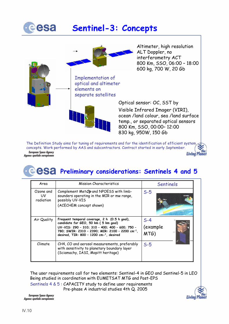
Altimeter, high resolution ALT Doppler, no interferometry ACT800 Km, SSO, 06:00 – 18:00600 kg, 700 W, 20 Gb
ocean /land colour, sea /land surface temp., or separated optical sensors800 Km, SSO, 00:00– 12:00830 kg, 950W, 150 Gb
Implementation of optical and altimeter elements on separate satellites
The Definition Study aims for tuning of requirements and for the identification of efficient system concepts. Work performed by AAS and subcontractors. Contract started in early September.
Sentinel-3: Concepts
Optical sensor: OC, SST by Visible Infrared Imager (VIRI),
Preliminary considerations: Sentinels 4 and 5
Area Mission Characteristics SentinelsOzone and
UV radiation
Complement MetOp and NPOESS with limb-sounders operating in the MIR or mw range, possibly UV-VIS(ACECHEM concept shown)
S-5
Air Quality Frequent temporal coverage, 2 h (0.5 h goal), candidate for GEO, 50 km ( 5 km goal) UV-VIS: 290 – 310; 310 – 400; 400 – 600; 750 –780; SWIR: 2310 – 2390; MIR: 2100 – 2200 cm-1,desired, TIR: 800 – 1200 cm-1, desired
S-4(exampleMTG)
Climate CH4, CO and aerosol measurements, preferably with sensitivity to planetary boundary layer (Sciamachy, IASI, Mopitt heritage)
S-5
The user requirements call for two elements: Sentinel-4 in GEO and Sentinel-5 in LEOBeing studied in coordination with EUMETSAT MTG and Post-EPSSentinels 4 & 5 : CAPACITY study to define user requirements
Pre-phase A industrial studies 4th Q. 2005
IV.10
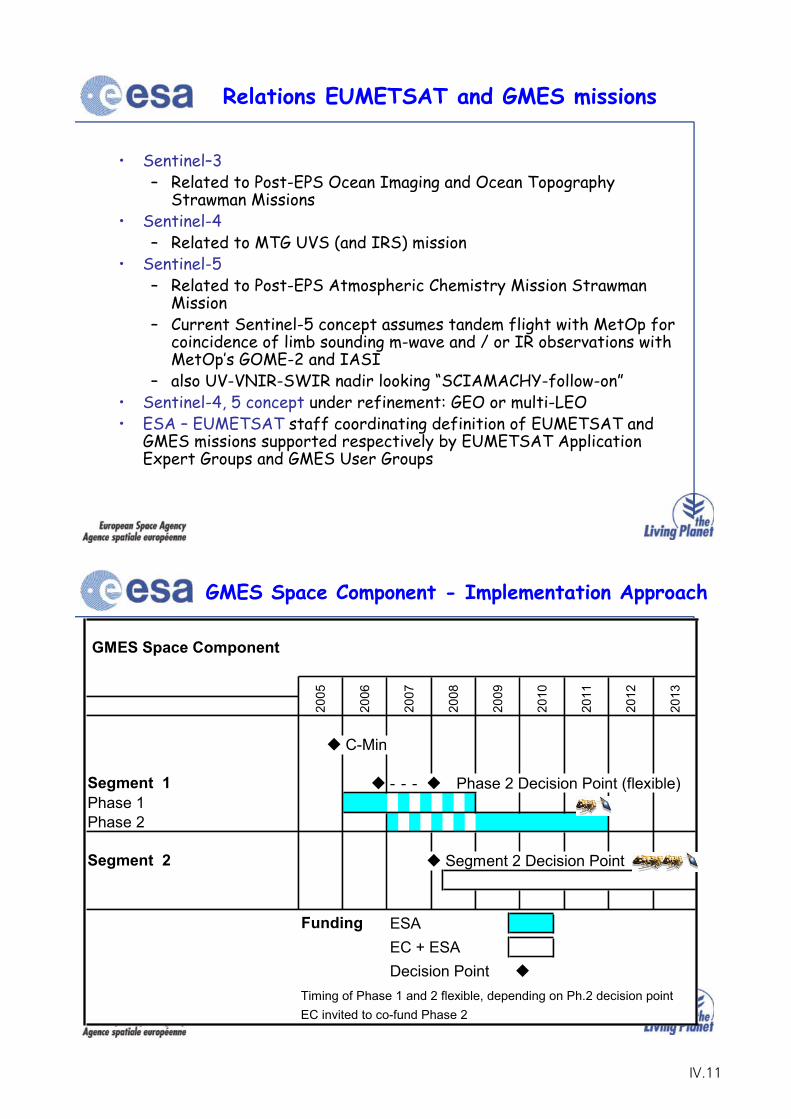
• Sentinel–3– Related to Post-EPS Ocean Imaging and Ocean Topography
Strawman Missions• Sentinel-4
– Related to MTG UVS (and IRS) mission• Sentinel-5
– Related to Post-EPS Atmospheric Chemistry Mission StrawmanMission
– Current Sentinel-5 concept assumes tandem flight with MetOp for coincidence of limb sounding m-wave and / or IR observations with MetOp’s GOME-2 and IASI
– also UV-VNIR-SWIR nadir looking “SCIAMACHY-follow-on”• Sentinel-4, 5 concept under refinement: GEO or multi-LEO• ESA – EUMETSAT staff coordinating definition of EUMETSAT and
GMES missions supported respectively by EUMETSAT Application Expert Groups and GMES User Groups
Relations EUMETSAT and GMES missions
GMES Space Component - Implementation Approach
GMES Space Component
C-Min
Segment 1 - - - Phase 2 Decision Point (flexible)Phase 1Phase 2
Segment 2 Segment 2 Decision Point
Funding ESAEC + ESADecision Point
Timing of Phase 1 and 2 flexible, depending on Ph.2 decision pointEC invited to co-fund Phase 2
2011
2012
2013
2007
2008
2009
2010
2005
2006
IV.11
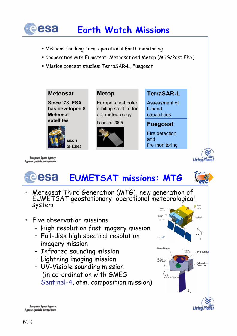
Earth Watch Missions
Missions for long-term operational Earth monitoring
Cooperation with Eumetsat: Meteosat and Metop (MTG/Post EPS)
Mission concept studies: TerraSAR-L, Fuegosat
MeteosatSince ’78, ESA has developed 8 Meteosatsatellites
MetopEurope’s first polar orbiting satellite for op. meteorologyLaunch: 2005
TerraSAR-LAssessment ofL-bandcapabilities
FuegosatFire detectionandfire monitoring
MSG-1
29.8.2002
• Meteosat Third Generation (MTG), new generation of EUMETSAT geostationary operational meteorological system
• Five observation missions– High resolution fast imagery mission – Full-disk high spectral resolution
imagery mission– Infrared sounding mission– Lightning imaging mission– UV-Visible sounding mission
(in co-ordination with GMESSentinel-4, atm. composition mission)
EUMETSAT missions: MTG
Combined Imager
LightningImager
UHF patch
L-band antenna
North or
South
Earth
Xs
Zs
Ys
Xs
Zs
Ys
IR-Sounder
X-BandAntenna
S-BandAntenna
XNadirLaunch Direction
DeepSpace
Y
Z
Main Body
IV.12
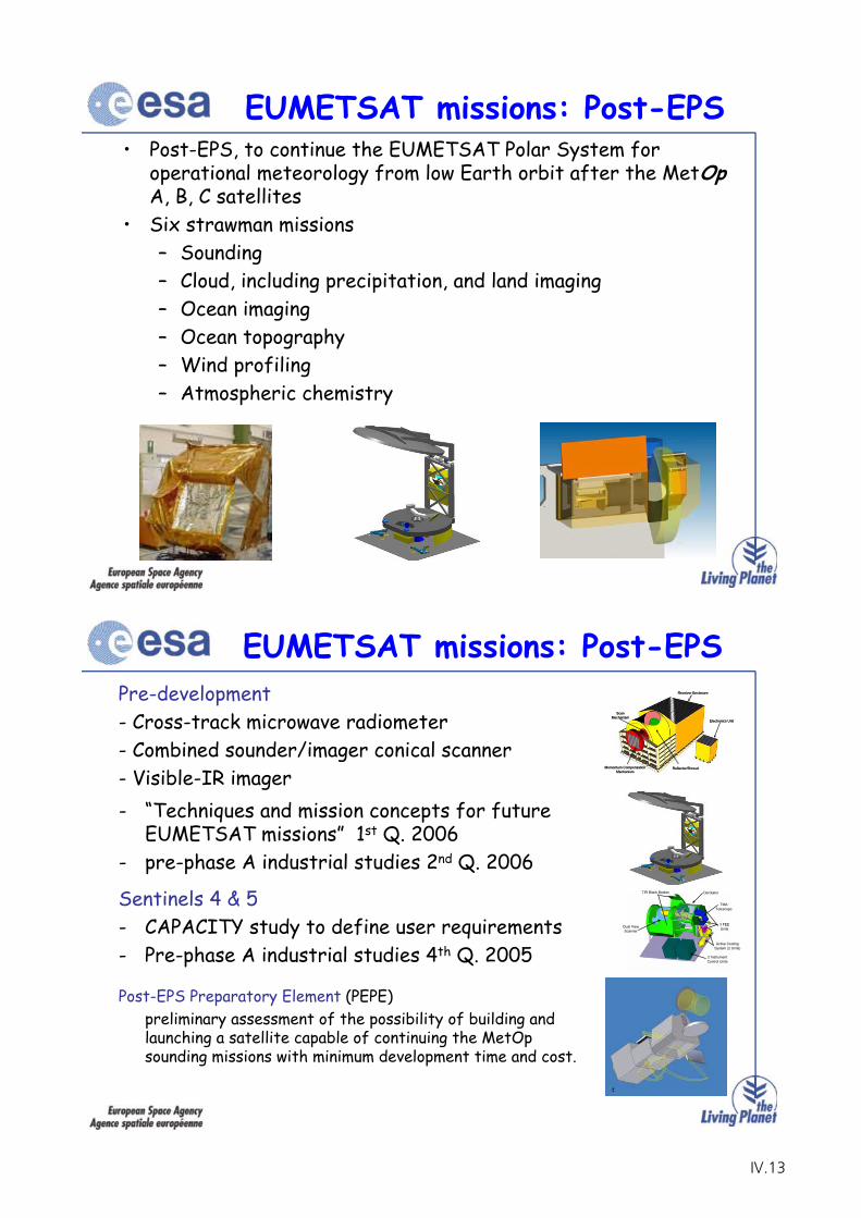
• Post-EPS, to continue the EUMETSAT Polar System for operational meteorology from low Earth orbit after the MetOpA, B, C satellites
• Six strawman missions– Sounding– Cloud, including precipitation, and land imaging– Ocean imaging– Ocean topography– Wind profiling– Atmospheric chemistry
EUMETSAT missions: Post-EPS
Pre-development- Cross-track microwave radiometer- Combined sounder/imager conical scanner- Visible-IR imager
EUMETSAT missions: Post-EPSReceiver Enclosure
ScanMechanism
Electronics Unit
Momentum CompensationMechanism
Reflector/Shroud
Receiver EnclosureReceiver Enclosure
ScanMechanism
ScanMechanism
Electronics UnitElectronics Unit
Momentum CompensationMechanism
Momentum CompensationMechanism
Reflector/ShroudReflector/Shroud
Derotator
TMATelescope
3 FEEUnits
Active CoolingSystem (2 Units)
Dual ViewScanner
TIR Black Bodies
2 InstrumentControl Units
- “Techniques and mission concepts for future EUMETSAT missions” 1st Q. 2006
- pre-phase A industrial studies 2nd Q. 2006
Sentinels 4 & 5- CAPACITY study to define user requirements- Pre-phase A industrial studies 4th Q. 2005
Post-EPS Preparatory Element (PEPE)preliminary assessment of the possibility of building and launching a satellite capable of continuing the MetOpsounding missions with minimum development time and cost.
IV.13
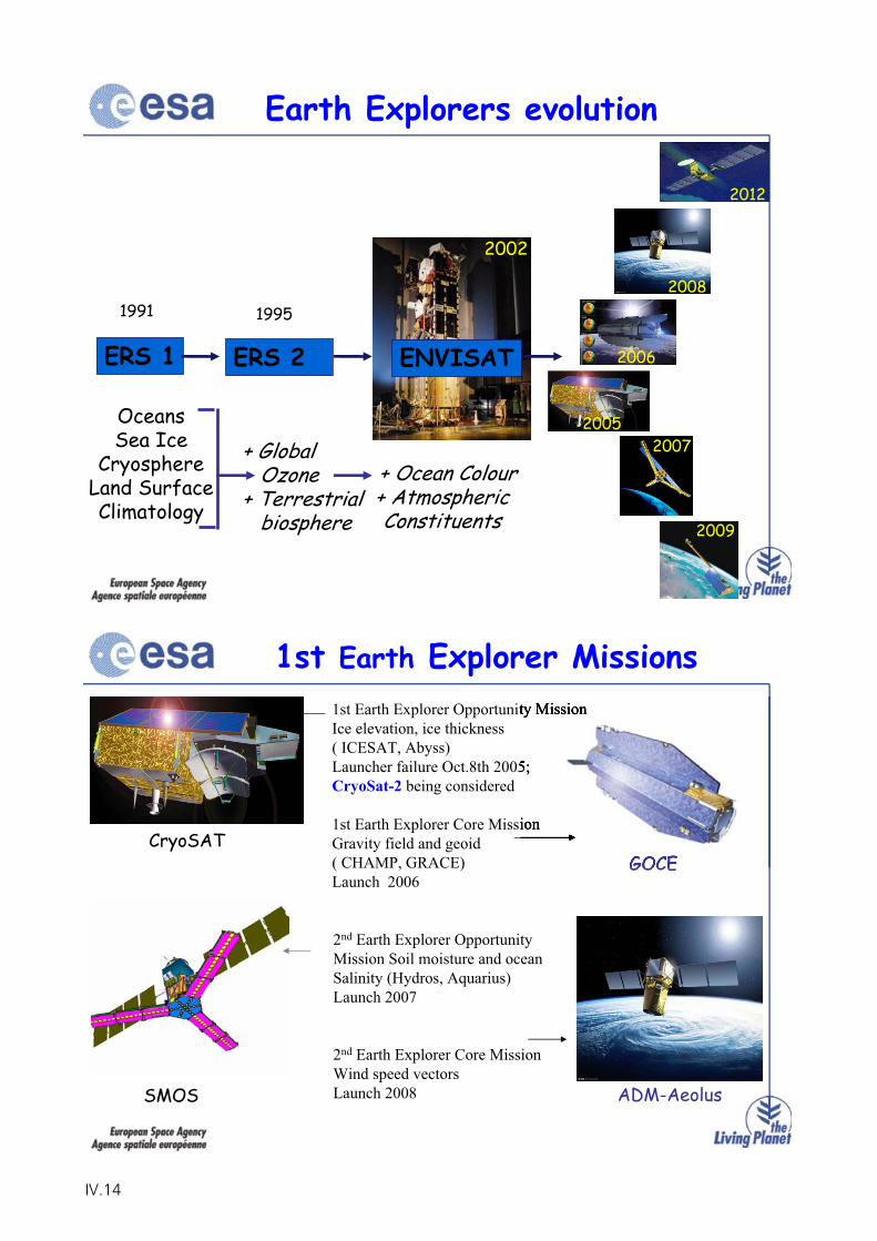
ERS 1 ERS 2
OceansSea Ice
CryosphereLand SurfaceClimatology
+ Global Ozone
+ Terrestrial biosphere
+ Ocean Colour+ Atmospheric Constituents
1991 1995
ENVISAT
2002
Earth Explorers evolution
2005
2006
2007
2009
2012
2008
1st Earth Explorer Missions1st Earth Explorer Opportunity MissionIce elevation, ice thickness( ICESAT, Abyss)Launcher failure Oct.8th 2005; CryoSat-2 being considered
1st Earth Explorer Core MissionGravity field and geoid( CHAMP, GRACE)Launch 2006
2nd Earth Explorer Opportunity Mission Soil moisture and ocean Salinity (Hydros, Aquarius)Launch 2007
2nd Earth Explorer Core MissionWind speed vectorsLaunch 2008
CryoSATGOCE
SMOS ADM-Aeolus
IV.14
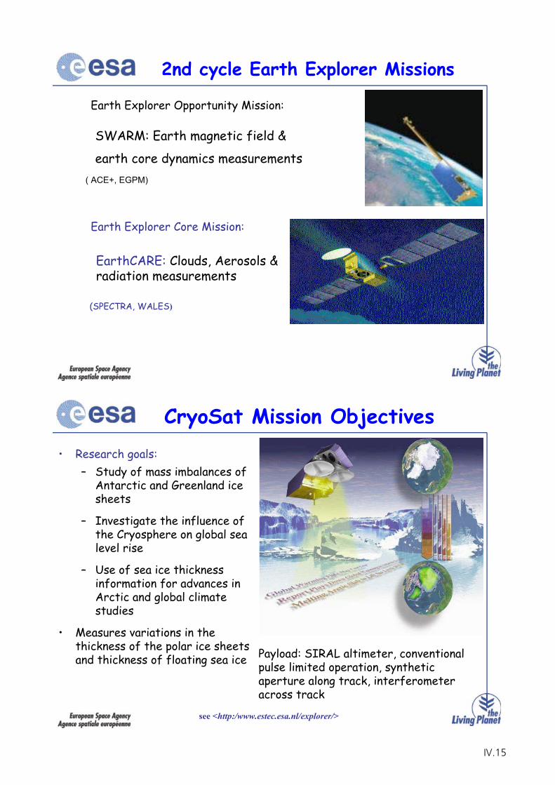
( ACE+, EGPM)
Earth Explorer Opportunity Mission:
2nd cycle Earth Explorer Missions
Earth Explorer Core Mission:
(SPECTRA, WALES)
SWARM: Earth magnetic field &
earth core dynamics measurements
EarthCARE: Clouds, Aerosols & radiation measurements
CryoSat Mission Objectives• Research goals:
– Study of mass imbalances of Antarctic and Greenland ice sheets
– Investigate the influence of the Cryosphere on global sea level rise
– Use of sea ice thickness information for advances in Arctic and global climate studies
• Measures variations in the thickness of the polar ice sheets and thickness of floating sea ice
see <http:/www.estec.esa.nl/explorer/>
Payload: SIRAL altimeter, conventional pulse limited operation, synthetic aperture along track, interferometer across track
IV.15
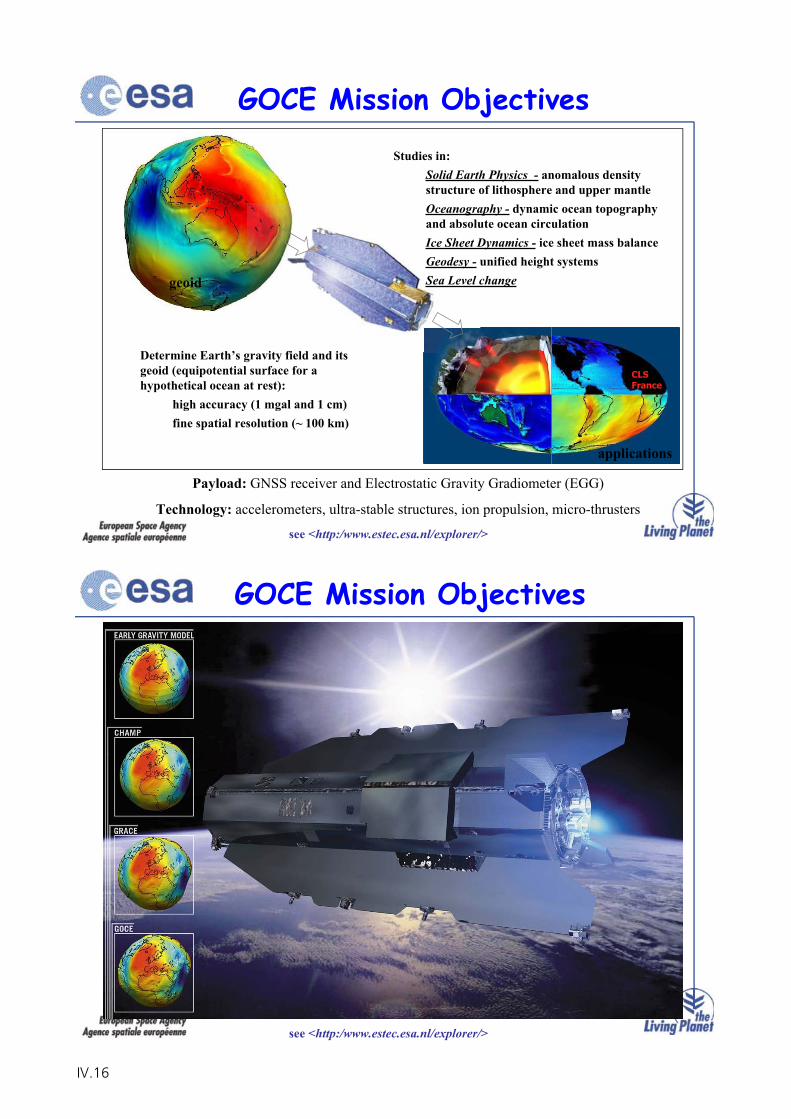
CLSFrance
Determine Earth’s gravity field and its geoid (equipotential surface for a hypothetical ocean at rest):
high accuracy (1 mgal and 1 cm) fine spatial resolution (~ 100 km)
Studies in:Solid Earth Physics - anomalous density structure of lithosphere and upper mantleOceanography - dynamic ocean topography and absolute ocean circulationIce Sheet Dynamics - ice sheet mass balanceGeodesy - unified height systemsSea Level change
GOCE Mission Objectives
see <http:/www.estec.esa.nl/explorer/>
Payload: GNSS receiver and Electrostatic Gravity Gradiometer (EGG)
Technology: accelerometers, ultra-stable structures, ion propulsion, micro-thrusters
geoid
applications
GOCE Mission Objectives
see <http:/www.estec.esa.nl/explorer/>
IV.16
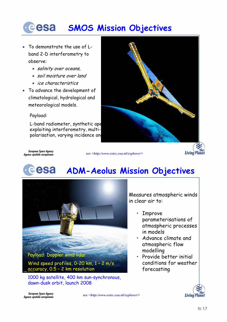
SMOS Mission Objectives
To demonstrate the use of L-band 2-D interferometry to observe:
salinity over oceans, soil moisture over landice characteristics
To advance the development of climatological, hydrological and meteorological models.
see <http:/www.estec.esa.nl/explorer/>
Payload:
L-band radiometer, synthetic aperture, exploiting interferometry, multi-polarisation, varying incidence angle
ADM-Aeolus Mission Objectives
Measures atmospheric winds in clear air to:
• Improve parameterisations of atmospheric processes in models
• Advance climate and atmospheric flow modelling
• Provide better initial conditions for weather forecasting
see <http:/www.estec.esa.nl/explorer/>
Payload: Doppler wind lidar
Wind speed profiles, 0-20 km, 1 – 2 m/s accuracy, 0.5 – 2 km resolution
1000 kg satellite, 400 km sun-synchronous, dawn-dusk orbit, launch 2008
IV.17
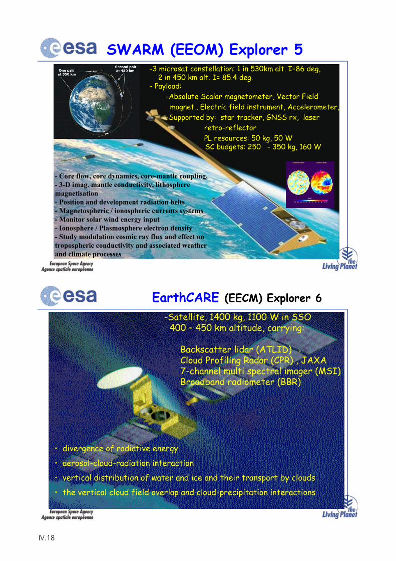
SWARM (EEOM) Explorer 5
- Core flow, core dynamics, core-mantle coupling,- 3-D imag. mantle conductivity, lithosphere magnetisation- Position and development radiation belts- Magnetospheric / ionospheric currents systems- Monitor solar wind energy input- Ionosphere / Plasmosphere electron density- Study modulation cosmic ray flux and effect on tropospheric conductivity and associated weather and climate processes
-3 microsat constellation: 1 in 530km alt. I=86 deg, 2 in 450 km alt. I= 85.4 deg.
- Payload:-Absolute Scalar magnetometer, Vector Field magnet., Electric field instrument, Accelerometer,
-Supported by: star tracker, GNSS rx, laser retro-reflectorPL resources: 50 kg, 50 WSC budgets: 250 - 350 kg, 160 W
EarthCARE (EECM) Explorer 6-Satellite, 1400 kg, 1100 W in SSO
400 – 450 km altitude, carrying:
Backscatter lidar (ATLID)Cloud Profiling Radar (CPR) , JAXA7-channel multi spectral imager (MSI)Broadband radiometer (BBR)
• divergence of radiative energy
• aerosol-cloud-radiation interaction
• vertical distribution of water and ice and their transport by clouds
• the vertical cloud field overlap and cloud-precipitation interactions
IV.18
3RD Call for Ideas EECM
The 3rd call for ideas for the (300M€) Earth Explorer Core Missions (EECM) overall schedule and priorities:
(http://www.esa.int/livingplanet/explorer/)
Scientific priorities applicable to the 3rd call:- Global water/carbon cycle - Atmospheric chemistry and climate -Human factor
-Release of the call – March 15, 2005
-Announcement of results (<= 6) of evaluation – May , 2006- User consultation in 2008, results of (<=3) Phase A
3RD Call for Ideas EECM
- 31 letters of intent received
- 24 mission proposals received
- 2 from GEO, 22 from LEO
- 4 multi-satellite, 20 single satellite
- 5 use lidars, for vegetation canopy, water vapour and CO2
- 2 exploit microwave and optical signals in occultation geometries
- 7 use radars, P-band (2), X+Ku (1), Ka (1), Ku+Ka (1), L (1)
(http://www.esa.int/livingplanet/explorer/)
IV.19
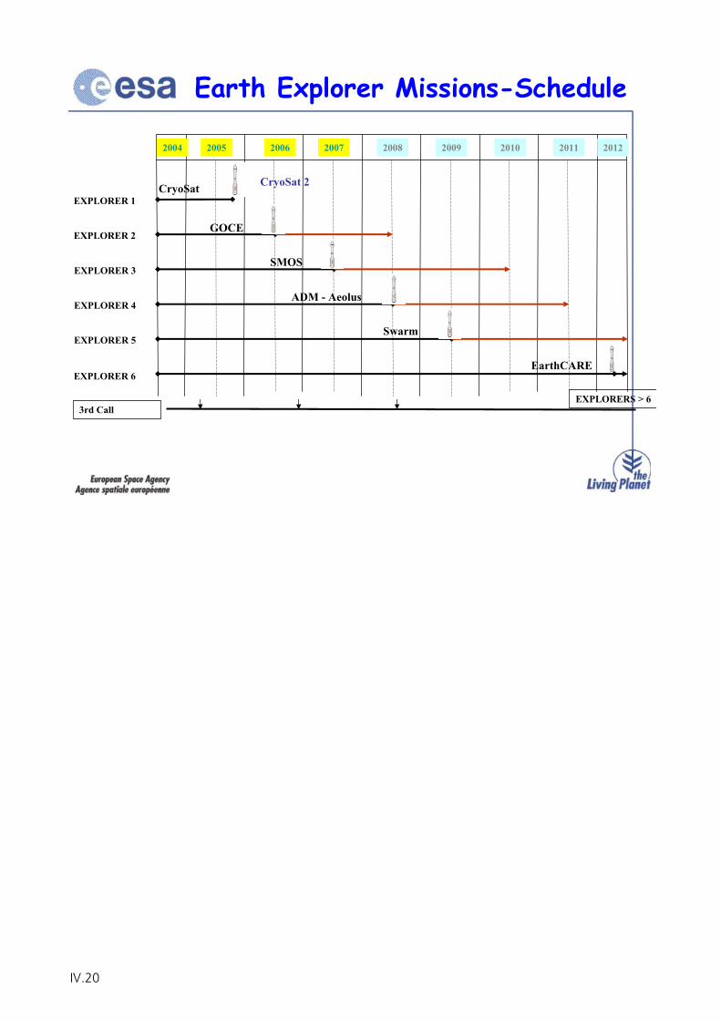
3rd Call
2005 201020092008200720062004 20122011
EXPLORER 2
EXPLORER 1
EXPLORER 3
EXPLORER 4
EXPLORER 5
EXPLORER 6
CryoSat
GOCE
SMOS
ADM - Aeolus
Swarm
EXPLORERS > 6
EarthCARE
Earth Explorer Missions-Schedule
CryoSat 2
IV.20
MTG User Requirements
Dr. R. Stuhlmann EUMETSAT
IV.21

IV.22
Page 1DWD/DLR Nutzertreffen, Walberberg 7-9 NovemberMET/RSt 04.11.05
2 1
Meteosat Third Generation (MTG):
Vorgeschlagene Beobachtungsmissionen
zur Erfüllung von Nutzeranforderungen
R. Stuhlmann1, A. Rodriguez1, P. Benzi2, D. Aminou2, and J.-L. Bezy2
Operationelle Satellitensysteme der Erdüberwachung
DWD/DLR Nationaler Nutzerworkshop
7 - 9 November, Walberberg
Page 2DWD/DLR Nutzertreffen, Walberberg 7-9 NovemberMET/RSt 04.11.05
— EinleitungMTG User Consultation Process
— MTG Kandidat Imagery MissionenHRFI MissionFDHSI MissionFC Missionskonzept
— MTG Kandidat Lightning Mission
— MTG Kandidat InfraRed Sounding Mission
— UV Sounding Mission
— Zusammenfassung
Inhalt
IV.23
Page 3DWD/DLR Nutzertreffen, Walberberg 7-9 NovemberMET/RSt 04.11.05
Schritt 1: Erfassung von Nutzer/Service Anforderungen für den Zeitrahmen2015 - 2025 und deren Ordnung nach Prioritäten
Schritt 2: Ableitung der zugehörigen ‘Beobachtungsanforderungen’:Beobachtungsrate;horizontale/vertikale Auflösung;Genauigkeit,Überdeckung,
bezüglich dreier Anforderungsniveaus:“threshold”: unterhalb ist die Beobachtung wertlos;“goal”´: oberhalb liefert die Beobachtung keine zusätzliche Information;“breakthrough”: Sprung im Informationsgewinn für den untersuchten Service
dokumentiert für MTG in 3 Positionspapieren, indossiert vom EUMETSAT Council‘Observation Reqiuirements for Nowcasting and Very Short Range Forecasting2015-2025’‘Requirements of Observations for Regional NWP 2015-2025’‘Requirements for Observations for Global NWP 2015-2025’
MTG User Consultation Process/AEGs
Page 4DWD/DLR Nutzertreffen, Walberberg 7-9 NovemberMET/RSt 04.11.05
Schritt 3: Analyse der Nutzer/Service- und zugehöriger Beobachtungs-anforderungen bezüglich möglicher Satelliten Konzepte in 2015 - 2025
- ausschließen was physikalisch nicht möglich ist- charakteresieren des erreichbaren Niveaus (e.g. threshold, breakthrough, goal)- ordnen bezüglich GEO (dt < 1h) oder LEO (dt > 1 h) Orbit Kandidat
Schritt 4: Ergebnisse präsentiert am 1st Post-MSG User Consultation Workshop
Schritt 5: EUMETSAT Council indossiert WS Empfehlungen und beauftragt: Konsolidierung der Nutzer/Service Anforderungen bezüglich:
‘Anwendungen Luftchemie/Luftqualität’‘Klimaüberwachung’
Bewertung spezieller Beobachtungkonzepte vom geostationären Orbit:‘Multi-spectral Imagery’‘Hyperspectral InfraRed Sounding’‘Lightning Imagery’‘Passive mm and sub-mm Observations’‘UV-VIS Sounding’
MTG User Consultation Process/RSEs
IV.24
Page 5DWD/DLR Nutzertreffen, Walberberg 7-9 NovemberMET/RSt 04.11.05
Schritt 6: Konsolidierung der Nutzer/Service Anforderung und Bewertungpotentieller Beobachtungskonzepte liefert fünf Missionen alsKandidaten für MTG pre-phase A Studien auf Systemebene:
• Drei ‘Imagery’ Missionen - Unterstützung operationeller Meteorologie/(Klima), mit Betonung auf ‘Nowcasting/Very Short Term Forecasting (NWC):
‘Regionale’ Imagery Mission mit hoher räumlicher/zeitlicherAuflösung (HRFI)(Nachfolger der MSG HR-VIS Kanal Mission X ~ 500m, BRC ~ 5 min)
‘Globale’ Imagery Mission mit hoher spectraler Auflösung (FDHSI)(Nachfolger der MSG SEVIRI mission X ~ 3000m, BRC ~ 15 min)
‘Lightning’ Imagery (LI) mission
• InfraRed Sounding (IRS) Mission - Hauptziel operationelle Meteorologie/(Klima), und Potential zur Unterstützung von AtmosphärenChemie Anwendungen
• UV/Visible Sounding (UVS) Mission - speziell für AtmosphärenChemie
MTG Kandidat Beobachtungsmissionen
Page 6DWD/DLR Nutzertreffen, Walberberg 7-9 NovemberMET/RSt 04.11.05
Grundsätzliche/übergreifende Nutzeranforderungen:
- Erweiterung der Anwendungen des MSG HR-VIS Kanales; Hauptziel - Erfassung von Konvektion und zugehörige schnellezeitliche Entwicklung der Komponenten des hydrologischen Zyklus,um durch Beobachtungen über ausgewählten Gebieten zurMinderung schwerer Sturmschäden beizutragen.
Notwendigkeit einer ‘qualitativen’ Datenanalyse zur Bereitstellung‘relativer Änderungen / schneller Entwicklungen’ als Produkte zurUntersützung von NWC
Kandidat HRFI Mission
IV.25
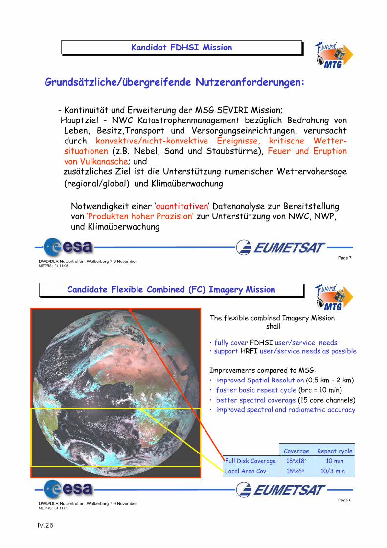
Page 7DWD/DLR Nutzertreffen, Walberberg 7-9 NovemberMET/RSt 04.11.05
- Kontinuität und Erweiterung der MSG SEVIRI Mission;Hauptziel - NWC Katastrophenmanagement bezüglich Bedrohung von Leben, Besitz,Transport und Versorgungseinrichtungen, verursachtdurch konvektive/nicht-konvektive Ereignisse, kritische Wetter-situationen (z.B. Nebel, Sand und Staubstürme), Feuer und Eruption von Vulkanasche; und zusätzliches Ziel ist die Unterstützung numerischer Wettervohersage(regional/global) und Klimaüberwachung
Notwendigkeit einer ‘quantitativen’ Datenanalyse zur Bereitstellungvon ‘Produkten hoher Präzision’ zur Unterstützung von NWC, NWP,und Klimaüberwachung
Grundsätzliche/übergreifende Nutzeranforderungen:
Kandidat FDHSI Mission
Page 8DWD/DLR Nutzertreffen, Walberberg 7-9 NovemberMET/RSt 04.11.05
Candidate Flexible Combined (FC) Imagery Mission
Coverage Repeat cycle Full Disk Coverage 18ox18o 10 minLocal Area Cov. 18ox6o 10/3 min
The flexible combined Imagery Mission shall
• fully cover FDHSI user/service needs• support HRFI user/service needs as possible
Improvements compared to MSG:• improved Spatial Resolution 0.5 km - 2 km)• faster basic repeat cycle (brc = 10 min)• better spectral coverage (15 core channels)• improved spectral and radiometric accuracy
IV.26
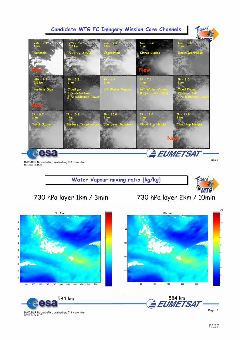
Page 9DWD/DLR Nutzertreffen, Walberberg 7-9 NovemberMET/RSt 04.11.05
VIS - 0.41 km
Aerosols
VIS - 0.60.5 km
Surface Albedo
VIS - 0.81 km
Vegetation
NIR - 1.31 km
Cirrus Clouds
NIR - 1.61 km
Snow/Ice/Phase
NIR - 2.10.5 km
Particle Size
IR - 6.72 km
UT Water Vapour
IR - 7.31 km
MT Water Vapour(Upper Level SO2)
IR - 8.52 km
Cloud PhaseVolcanic AshFire Radiative Power
IR - 9.72 km
Total Ozone
IR - 12.02 km
Low Level Moisture
IR - 13.02 km
Cloud Top Height
IR - 13.92 km
Cloud top Height
IR - 3.81 km
Cloud μFire detectionFire Radiative Power
IR - 10.81 km
Surface Temperature
Candidate MTG FC Imagery Mission Core Channels
New
New
New
New
Page 10DWD/DLR Nutzertreffen, Walberberg 7-9 NovemberMET/RSt 04.11.05
730 hPa layer 1km / 3min
584 km
484
km
484
km
730 hPa layer 2km / 10min
584 km
Water Vapour mixing ratio [kg/kg]
IV.27
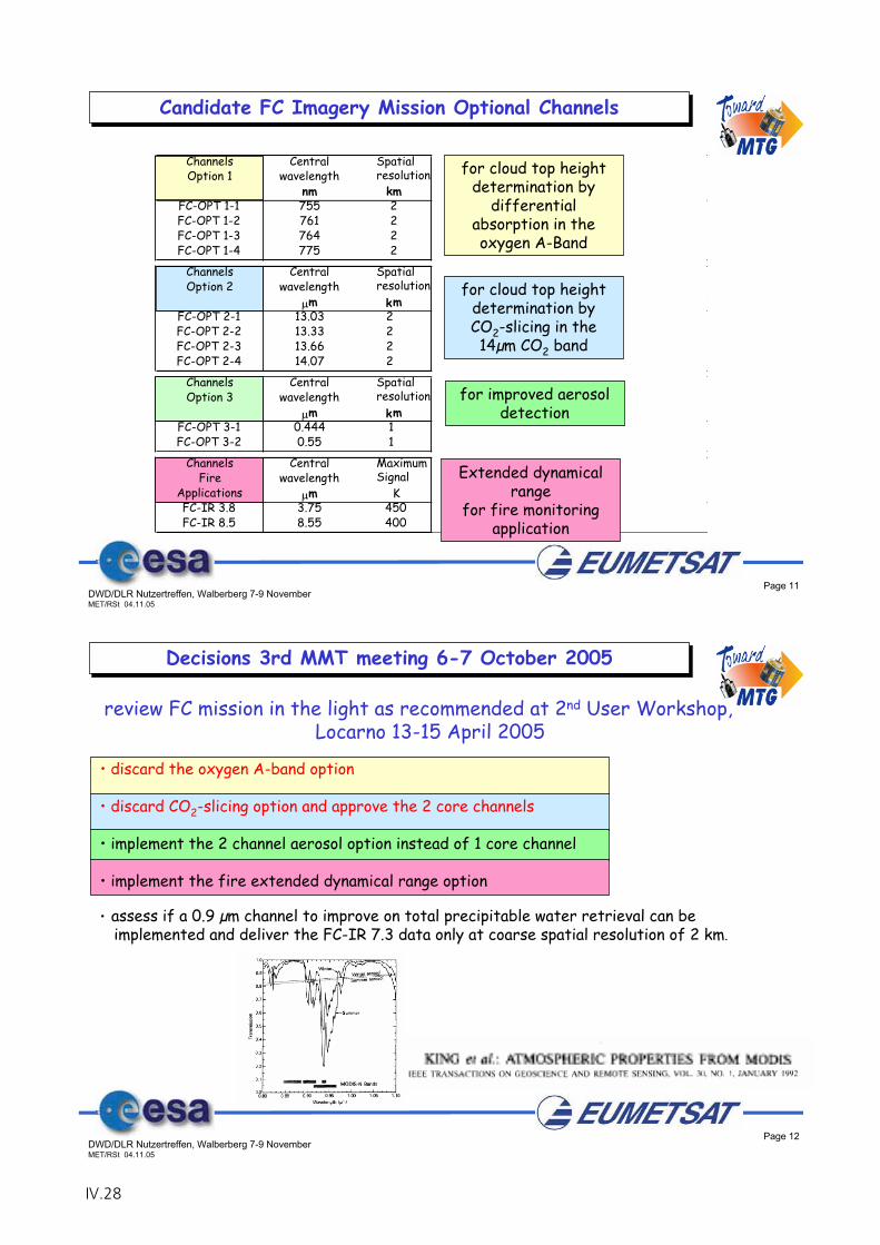
Page 11DWD/DLR Nutzertreffen, Walberberg 7-9 NovemberMET/RSt 04.11.05
Channels Central Spatialresolution
Maximum Reference SNR@
2x2km2Option 1 wavelength Signal Signal
nm kmFC-OPT 1-1 755 2 380 100 100FC-OPT 1-2 761 2 380 100 100FC-OPT 1-3 764 2 380 100 100FC-OPT 1-4 775 2 5 380 100 100
Channels Central Spatialresolution
Minimum Maximum Reference NEdT@2x2km2
Option 2 wavelength Signal Signal Signalm km
FC-OPT 2-1 13.03 2 165 300 270 0.3FC-OPT 2-2 13.33 2 165 300 250 0.3FC-OPT 2-3 13.66 2 165 300 250 0.3FC-OPT 2-4 14.07 2 165 300 250 0.3
Channels Central Spatialresolution
Minimum Maximum Reference SNR@1x1km2
Option 3 wavelength Signal Signal Signalm km
FC-OPT 3-1 0.444 1 1% 120% 1% 30FC-OPT 3-2 0.55 1 1% 120% 1% 30
Channels Central MaximumSignal
Minimum Maximum Reference NEdT@2x2km2
Fire wavelength Signal Signal SignalApplications m KFC-IR 3.8 3.75 450 275 450 350 0.6FC-IR 8.5 8.55 400 250 400 330 0.6
Wm-2sr-1 m-1
K
K
Candidate FC Imagery Mission Optional Channels
for cloud top height determination by
differentialabsorption in the oxygen A-Band
for cloud top height determination by CO2-slicing in the 14μm CO2 band
Extended dynamical range
for fire monitoring application
for improved aerosol detection
Page 12DWD/DLR Nutzertreffen, Walberberg 7-9 NovemberMET/RSt 04.11.05
Decisions 3rd MMT meeting 6-7 October 2005
review FC mission in the light as recommended at 2nd User Workshop, Locarno 13-15 April 2005
• discard the oxygen A-band option
• discard CO2-slicing option and approve the 2 core channels
• implement the 2 channel aerosol option instead of 1 core channel
• implement the fire extended dynamical range option
• assess if a 0.9 μm channel to improve on total precipitable water retrieval can beimplemented and deliver the FC-IR 7.3 data only at coarse spatial resolution of 2 km.
IV.28
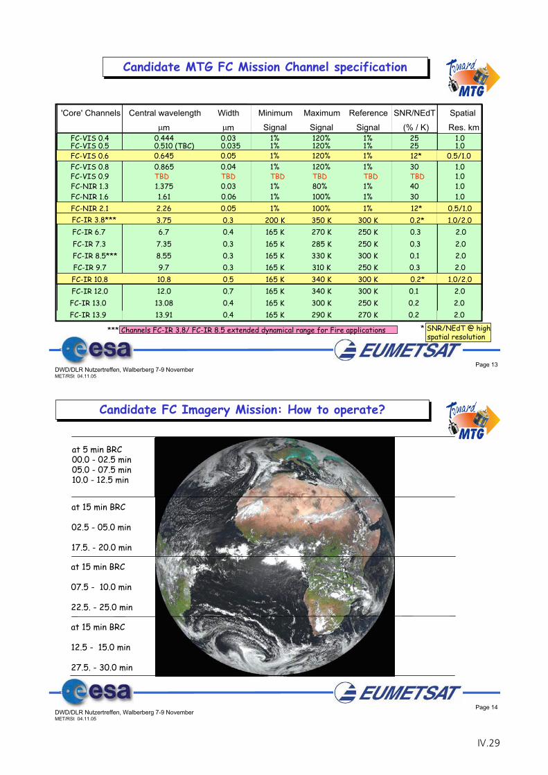
Page 13DWD/DLR Nutzertreffen, Walberberg 7-9 NovemberMET/RSt 04.11.05
'Core' Channels Central wavelength Width Minimum Maximum Reference SNR/NEdT
m m Signal Signal Signal (% / K) FC-VIS 0.4 0.444 0.03 1% 120% 1% 25
Candidate MTG FC Mission Channel specification
*** Channels FC-IR 3.8/ FC-IR 8.5 extended dynamical range for Fire applications
FC-VIS 0.6 0.645 0.05 1% 120% 1% 12*FC-VIS 0.8 0.865 0.04 1% 120% 1% 30
FC-NIR 1.3 1.375 0.03 1% 80% 1% 40FC-NIR 1.6 1.61 0.06 1% 100% 1% 30FC-NIR 2.1 2.26 0.05 1% 100% 1% 12*FC-IR 3.8*** 3.75 0.3 200 K 350 K 300 K 0.2* FC-IR 6.7 6.7 0.4 165 K 270 K 250 K 0.3FC-IR 7.3 7.35 0.3 165 K 285 K 250 K 0.3FC-IR 8.5*** 8.55 0.3 165 K 330 K 300 K 0.1FC-IR 9.7 9.7 0.3 165 K 310 K 250 K 0.3FC-IR 10.8 10.8 0.5 165 K 340 K 300 K 0.2*FC-IR 12.0 12.0 0.7 165 K 340 K 300 K 0.1FC-IR 13.0 13.08 0.4 165 K 300 K 250 K 0.2FC-IR 13.9 13.91 0.4 165 K 290 K 270 K 0.2
FC-VIS 0.5 0.510 (TBC) 0.035 1% 120% 1% 25
FC-VIS 0.9 TBD TBD TBD TBD TBD TBD
Spatial
Res. km1.0
0.5/1.01.0
1.01.0
0.5/1.01.0/2.0
2.02.02.02.0
1.0/2.02.02.02.0
1.0
1.0
* SNR/NEdT @ high spatial resolution
Page 14DWD/DLR Nutzertreffen, Walberberg 7-9 NovemberMET/RSt 04.11.05
Candidate FC Imagery Mission: How to operate?
at 5 min BRC00.0 - 02.5 min05.0 - 07.5 min10.0 - 12.5 min
at 15 min BRC
02.5 - 05.0 min
17.5. - 20.0 min
at 15 min BRC
07.5 - 10.0 min
22.5. - 25.0 min
at 15 min BRC
12.5 - 15.0 min
27.5. - 30.0 min
IV.29
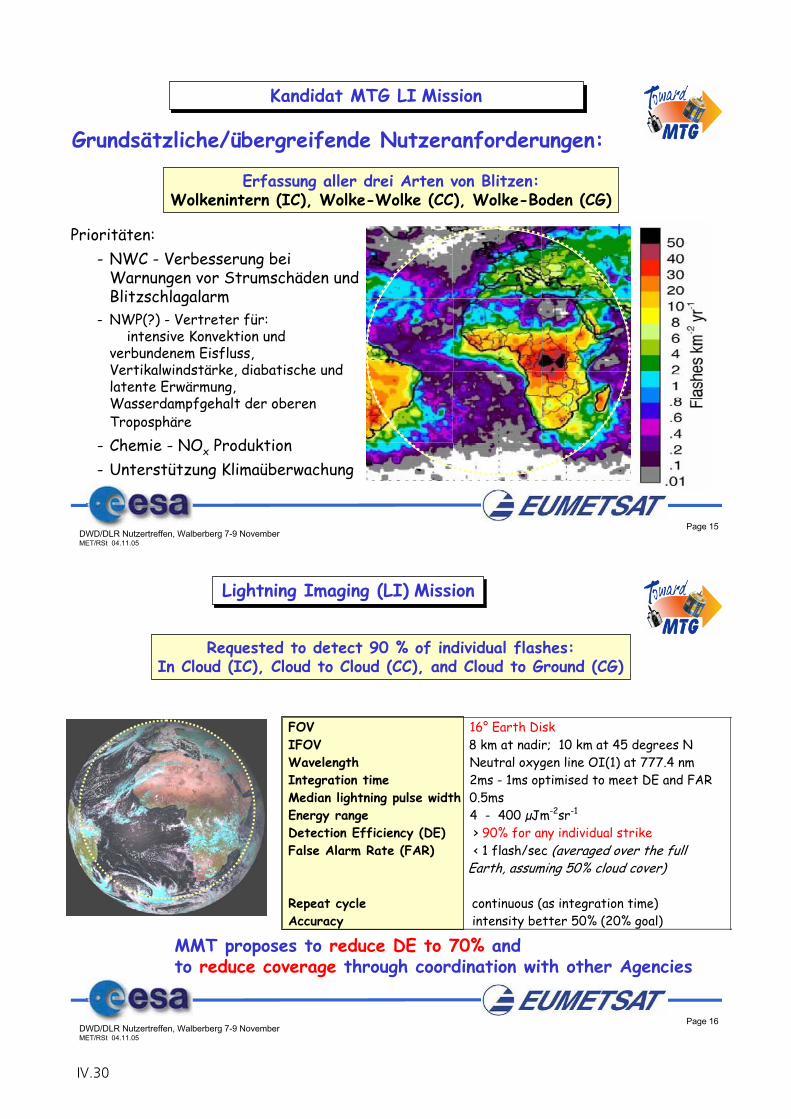
Page 15DWD/DLR Nutzertreffen, Walberberg 7-9 NovemberMET/RSt 04.11.05
Kandidat MTG LI Mission
Erfassung aller drei Arten von Blitzen:Wolkenintern (IC), Wolke-Wolke (CC), Wolke-Boden (CG)
Prioritäten:- NWC - Verbesserung bei
Warnungen vor Strumschäden und Blitzschlagalarm
- NWP(?) - Vertreter für: intensive Konvektion und
verbundenem Eisfluss, Vertikalwindstärke, diabatische und latente Erwärmung, Wasserdampfgehalt der oberenTroposphäre
- Chemie - NOx Produktion- Unterstützung Klimaüberwachung
Grundsätzliche/übergreifende Nutzeranforderungen:
Page 16DWD/DLR Nutzertreffen, Walberberg 7-9 NovemberMET/RSt 04.11.05
FOV 16° Earth DiskIFOV 8 km at nadir; 10 km at 45 degrees NWavelength Neutral oxygen line OI(1) at 777.4 nmIntegration time 2ms - 1ms optimised to meet DE and FARMedian lightning pulse width 0.5msEnergy range 4 - 400 μJm-2sr-1
Detection Efficiency (DE) > 90% for any individual strikeFalse Alarm Rate (FAR) < 1 flash/sec (averaged over the full Earth, assuming 50% cloud cover)
Repeat cycle continuous (as integration time)Accuracy intensity better 50% (20% goal)
Co-registration HRFI/FDHSI: better than 1 IFOV
Lightning Imaging (LI) Mission
Requested to detect 90 % of individual flashes:In Cloud (IC), Cloud to Cloud (CC), and Cloud to Ground (CG)
MMT proposes to reduce DE to 70% andto reduce coverage through coordination with other Agencies
IV.30
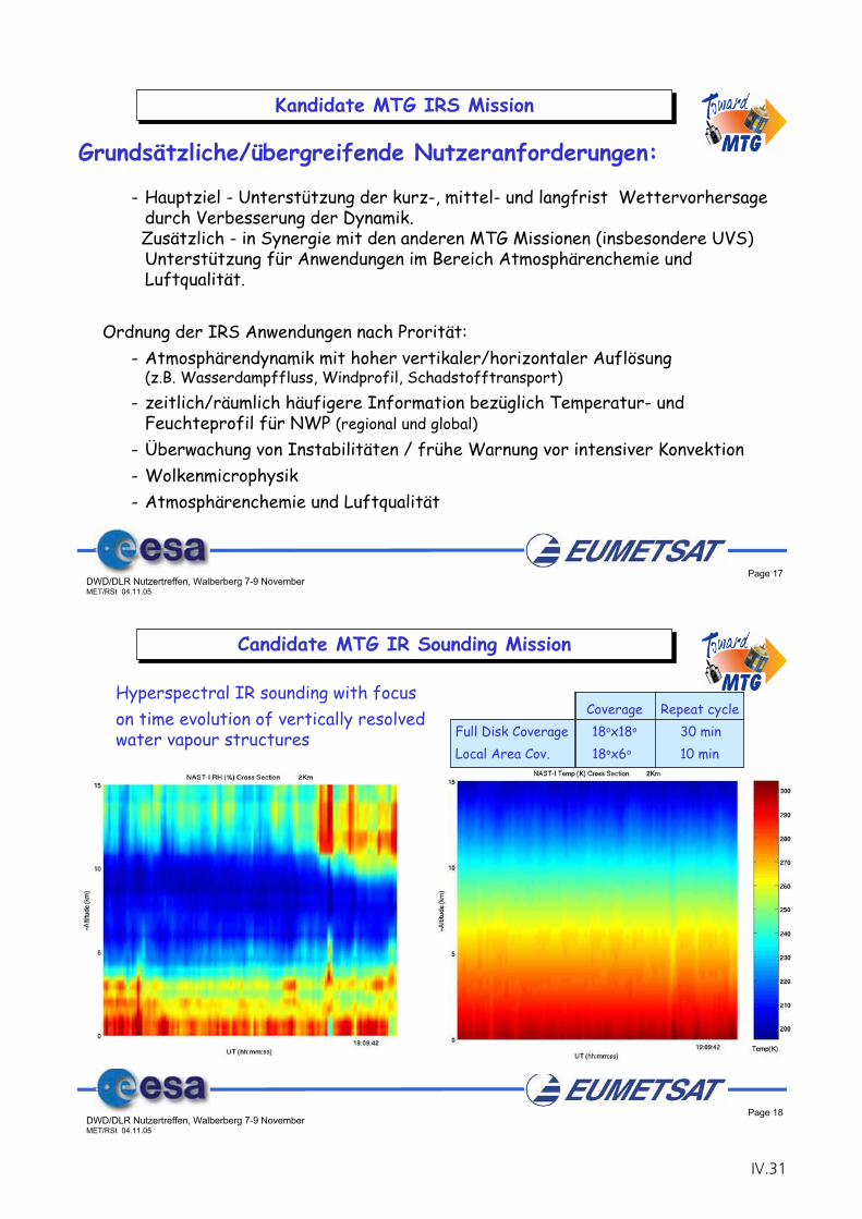
Page 17DWD/DLR Nutzertreffen, Walberberg 7-9 NovemberMET/RSt 04.11.05
- Hauptziel - Unterstützung der kurz-, mittel- und langfrist Wettervorhersagedurch Verbesserung der Dynamik.Zusätzlich - in Synergie mit den anderen MTG Missionen (insbesondere UVS) Unterstützung für Anwendungen im Bereich Atmosphärenchemie und Luftqualität.
Ordnung der IRS Anwendungen nach Prorität:- Atmosphärendynamik mit hoher vertikaler/horizontaler Auflösung
(z.B. Wasserdampffluss, Windprofil, Schadstofftransport)- zeitlich/räumlich häufigere Information bezüglich Temperatur- und
Feuchteprofil für NWP (regional und global)- Überwachung von Instabilitäten / frühe Warnung vor intensiver Konvektion- Wolkenmicrophysik- Atmosphärenchemie und Luftqualität
Kandidate MTG IRS Mission
Grundsätzliche/übergreifende Nutzeranforderungen:
Page 18DWD/DLR Nutzertreffen, Walberberg 7-9 NovemberMET/RSt 04.11.05
Candidate MTG IR Sounding Mission
Hyperspectral IR sounding with focuson time evolution of vertically resolved water vapour structures
Coverage Repeat cycle Full Disk Coverage 18ox18o 30 minLocal Area Cov. 18ox6o 10 min
IV.31
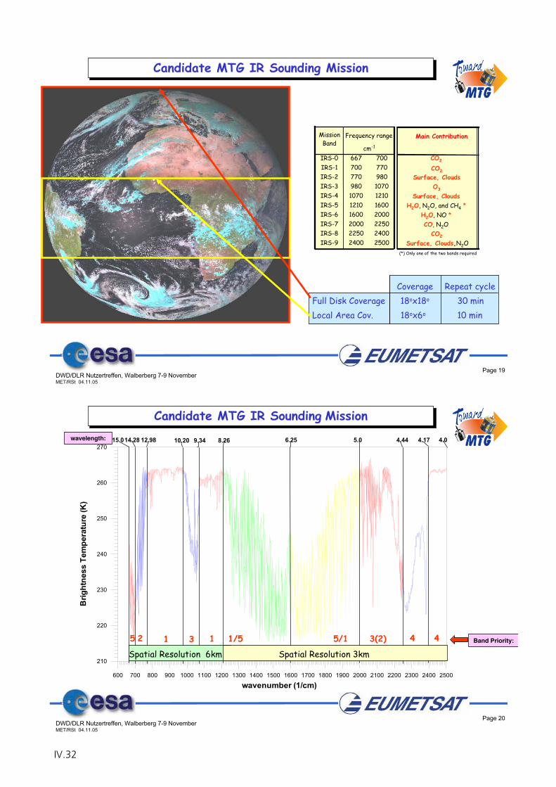
Page 19DWD/DLR Nutzertreffen, Walberberg 7-9 NovemberMET/RSt 04.11.05
Coverage Repeat cycle Full Disk Coverage 18ox18o 30 minLocal Area Cov. 18ox6o 10 min
Candidate MTG IR Sounding Mission
MissionBand
IRS-0 667 700IRS-1 700 770IRS-2 770 980IRS-3 980 1070IRS-4 1070 1210IRS-5 1210 1600IRS-6 1600 2000IRS-7 2000 2250IRS-8 2250 2400IRS-9 2400 2500
cm-1
Frequency range Main Contribution
CO2
CO2Surface, Clouds
O3
Surface, CloudsH2O, N2O, and CH4 *
H2O, NO *CO, N2O
CO2
Surface, Clouds,N2O(*) Only one of the two bands required
Page 20DWD/DLR Nutzertreffen, Walberberg 7-9 NovemberMET/RSt 04.11.05
600 700 800 900 1000 1100 1200 1300 1400 1500 1600 1700 1800 1900 2000 2100 2200 2300 2400 2500
wavenumber (1/cm)
210
220
230
240
250
260
270
Brig
htne
ss T
empe
ratu
re (K
)
wavelength: 15.0 14.28 12.98 10.20 9.34 8.26 6.25 5.0 4.44 4.17 4.0
Spatial Resolution 6km Spatial Resolution 3km
Candidate MTG IR Sounding Mission
Band Priority:1/5 5/1 3(2) 4 411 325
IV.32
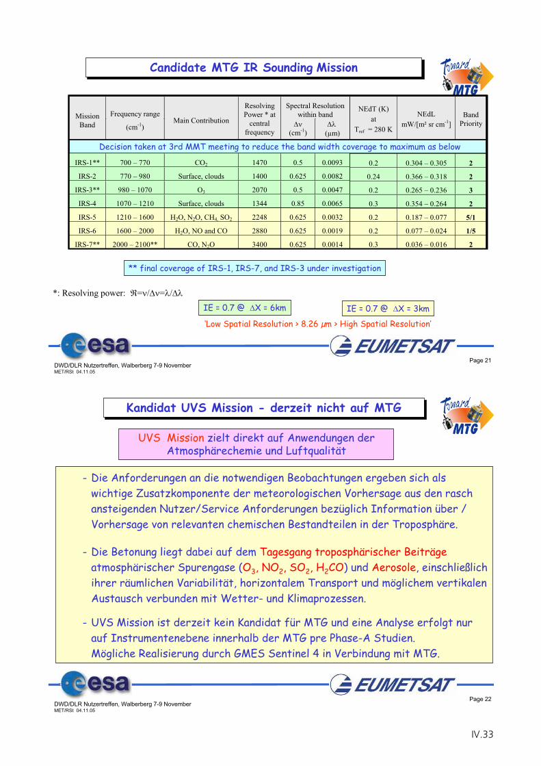
Page 21DWD/DLR Nutzertreffen, Walberberg 7-9 NovemberMET/RSt 04.11.05
NEdT (K)at
Tref = 280 K
NEdLmW/[m² sr cm-1]
BandPriority
TBD TBD 5
0.2 0.304 – 0.305 2
0.24 0.366 – 0.318 2
0.2 0.265 – 0.236 3
0.3 0.354 – 0.264 2
0.2 0.187 – 0.077 5/1
0.2 0.077 – 0.024 1/5
0.3 0.036 – 0.016 2
TBD TBD 4
TBD TBD 4
IE = 0.7 @ X = 6km IE = 0.7 @ X = 3km
‘Low Spatial Resolution > 8.26 μm > High Spatial Resolution’
Candidate MTG IR Sounding Mission
Spectral Resolutionwithin bandMission
BandFrequency range
(cm-1)Main Contribution
ResolvingPower * at
centralfrequency (cm-1) μm)
IRS-0 667 – 700 CO2 1367 0.5 0.0107
IRS-1** 700 – 770 CO2 1470 0.5 0.0093
IRS-2 770 – 980 Surface, clouds 1400 0.625 0.0082
IRS-3** 980 – 1070 O3 2070 0.5 0.0047
IRS-4 1070 – 1210 Surface, clouds 1344 0.85 0.0065
IRS-5 1210 – 1600 H2O, N2O, CH4, SO2 2248 0.625 0.0032
IRS-6 1600 – 2000 H2O, NO and CO 2880 0.625 0.0019
IRS-7** 2000 – 2100** CO, N2O 3400 0.625 0.0014
IRS-8 2250 – 2400 CO2 1860 1.25 0.0023
IRS-9 2400 – 2500 Surface, clouds, N2O 1000 2.45 0.004
*: Resolving power: = / = /
Decision taken at 3rd MMT meeting to reduce the band width coverage to maximum as below
** final coverage of IRS-1, IRS-7, and IRS-3 under investigation
Page 22DWD/DLR Nutzertreffen, Walberberg 7-9 NovemberMET/RSt 04.11.05
Kandidat UVS Mission - derzeit nicht auf MTG
- Die Anforderungen an die notwendigen Beobachtungen ergeben sich alswichtige Zusatzkomponente der meteorologischen Vorhersage aus den raschansteigenden Nutzer/Service Anforderungen bezüglich Information über / Vorhersage von relevanten chemischen Bestandteilen in der Troposphäre.
- Die Betonung liegt dabei auf dem Tagesgang troposphärischer Beiträgeatmosphärischer Spurengase (O3, NO2, SO2, H2CO) und Aerosole, einschließlichihrer räumlichen Variabilität, horizontalem Transport und möglichem vertikalenAustausch verbunden mit Wetter- und Klimaprozessen.
- UVS Mission ist derzeit kein Kandidat für MTG und eine Analyse erfolgt nurauf Instrumentenebene innerhalb der MTG pre Phase-A Studien.Mögliche Realisierung durch GMES Sentinel 4 in Verbindung mit MTG.
UVS Mission zielt direkt auf Anwendungen derAtmosphärechemie und Luftqualität
IV.33
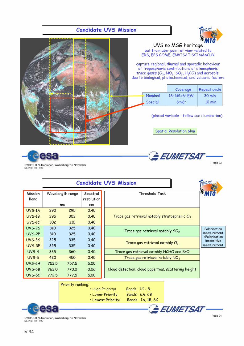
Page 23DWD/DLR Nutzertreffen, Walberberg 7-9 NovemberMET/RSt 04.11.05
(placed variable - follow sun illumination)
UVS no MSG heritagebut from user point of view related to
ERS, EPS GOME, ENVISAT SCIAMACHY
capture regional, diurnal and sporadic behaviourof tropospheric contributions of atmospheric
trace gases (O3, NO2, SO2, H2CO) and aerosols due to biological, photochemical, and volcanic factors
Coverage Repeat cycle Nominal 18o NSx6o EW 30 min Special 6ox6o 10 min
Spatial Resolution 6km
Candidate UVS Mission
Page 24DWD/DLR Nutzertreffen, Walberberg 7-9 NovemberMET/RSt 04.11.05
Candidate UVS Mission
Mission Spectral Threshold TaskBand resolution
nmUVS-1A 290 295 0.40UVS-1B 295 302 0.40UVS-1C 302 310 0.40UVS-2S 310 325 0.40UVS-2P 310 325 0.40UVS-3S 325 335 0.40UVS-3P 325 335 0.40UVS-4 335 360 0.40 Trace gas retrieval notably HCHO and BrOUVS-5 420 450 0.40 Trace gas retrieval notably NO2
UVS-6A 752.5 757.5 5.00UVS-6B 762.0 770.0 0.06UVS-6C 772.5 777.5 5.00
Trace gas retrieval notably stratospheric O3
Trace gas retrieval notably SO2
Trace gas retrieval notably O3
Cloud detection, cloud poperties, scattering height
Wavelength range
nm
Polarisation measurement/Polarisationinsensitive
measurement
Priority ranking:• High Priority: Bands 1C - 5• Lower Priority: Bands 6A, 6B• Lowest Priority: Bands 1A, 1B, 6C
IV.34
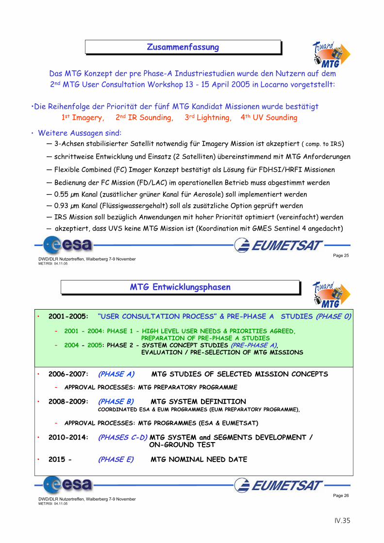
Page 25DWD/DLR Nutzertreffen, Walberberg 7-9 NovemberMET/RSt 04.11.05
Zusammenfassung
Das MTG Konzept der pre Phase-A Industriestudien wurde den Nutzern auf dem2nd MTG User Consultation Workshop 13 - 15 April 2005 in Locarno vorgetstellt:
•Die Reihenfolge der Priorität der fünf MTG Kandidat Missionen wurde bestätigt1st Imagery, 2nd IR Sounding, 3rd Lightning, 4th UV Sounding
• Weitere Aussagen sind: — 3-Achsen stabilisierter Satellit notwendig für Imagery Mission ist akzeptiert ( comp. to IRS)
— schrittweise Entwicklung und Einsatz (2 Satelliten) übereinstimmend mit MTG Anforderungen
— Flexible Combined (FC) Imager Konzept bestätigt als Lösung für FDHSI/HRFI Missionen
— Bedienung der FC Mission (FD/LAC) im operationellen Betrieb muss abgestimmt werden— 0.55 μm Kanal (zusätlicher grüner Kanal für Aerosole) soll implementiert werden— 0.93 μm Kanal (Flüssigwassergehalt) soll als zusätzliche Option geprüft werden— IRS Mission soll bezüglich Anwendungen mit hoher Priorität optimiert (vereinfacht) werden— akzeptiert, dass UVS keine MTG Mission ist (Koordination mit GMES Sentinel 4 angedacht)
Page 26DWD/DLR Nutzertreffen, Walberberg 7-9 NovemberMET/RSt 04.11.05
•• 20012001--20052005: “USER CONSULTATION PROCESS” & PRE-PHASE A STUDIES (PHASE 0)
– 2001 - 2004: PHASE 1 - HIGH LEVEL USER NEEDS & PRIORITIES AGREED, PREPARATION OF PRE-PHASE A STUDIES
– 2004 - 2005: PHASE 2 - SYSTEM CONCEPT STUDIES (PRE-PHASE A),EVALUATION / PRE-SELECTION OF MTG MISSIONS
•• 20062006--20072007: (PHASE A) MTG STUDIES OF SELECTED MISSION CONCEPTS
– APPROVAL PROCESSES: MTG PREPARATORY PROGRAMME
•• 20082008--20092009: (PHASE B) MTG SYSTEM DEFINITION COORDINATED ESA & EUM PROGRAMMES (EUM PREPARATORY PROGRAMME),
– APPROVAL PROCESSES: MTG PROGRAMMES (ESA & EUMETSAT)
•• 20102010--20142014: (PHASES C-D) MTG SYSTEM and SEGMENTS DEVELOPMENT / ON-GROUND TEST
•• 20152015 - (PHASE E) MTG NOMINAL NEED DATE
MTG Entwicklungsphasen
IV.35
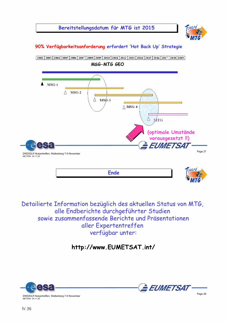
Page 27DWD/DLR Nutzertreffen, Walberberg 7-9 NovemberMET/RSt 04.11.05
Bereitstellungsdatum für MTG ist 2015
(optimale Umständevorausgesetzt !!)
90% Verfügbarkeitsanforderung erfordert ‘Hot Back Up’ Strategie
Page 28DWD/DLR Nutzertreffen, Walberberg 7-9 NovemberMET/RSt 04.11.05
Ende
Detailierte Information bezüglich des aktuellen Status von MTG, alle Endberichte durchgeführter Studien
sowie zusammenfassende Berichte und Präsentationenaller Expertentreffen
verfügbar unter:
http://www.EUMETSAT.int/
IV.36
Results of the MTG Pre-Phase A Studies
P. Bensi
ESA-ESTEC
IV.37

IV.38
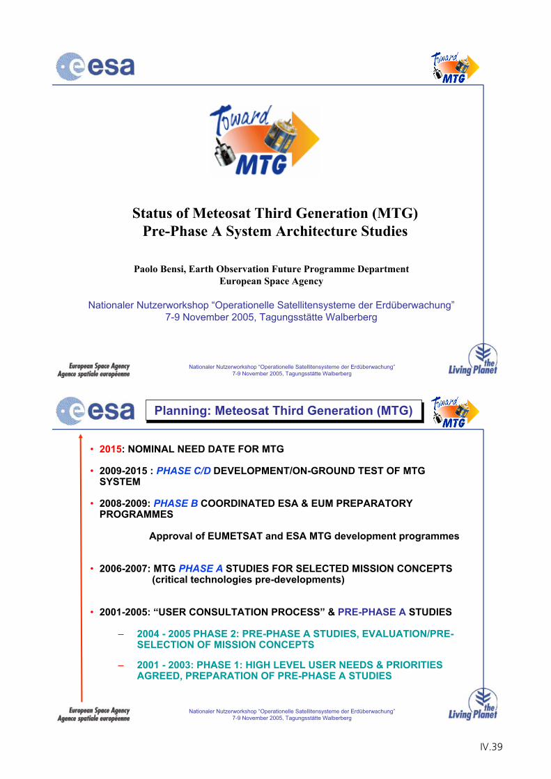
Nationaler Nutzerworkshop “Operationelle Satellitensysteme der Erdüberwachung”7-9 November 2005, Tagungsstätte Walberberg
Status of Meteosat Third Generation (MTG) Pre-Phase A System Architecture Studies
Paolo Bensi, Earth Observation Future Programme DepartmentEuropean Space Agency
Nationaler Nutzerworkshop “Operationelle Satellitensysteme der Erdüberwachung”7-9 November 2005, Tagungsstätte Walberberg
Nationaler Nutzerworkshop “Operationelle Satellitensysteme der Erdüberwachung”7-9 November 2005, Tagungsstätte Walberberg
• 2015: NOMINAL NEED DATE FOR MTG
• 2009-2015 : PHASE C/D DEVELOPMENT/ON-GROUND TEST OF MTG SYSTEM
• 2008-2009: PHASE B COORDINATED ESA & EUM PREPARATORY PROGRAMMES
Approval of EUMETSAT and ESA MTG development programmes
• 2006-2007: MTG PHASE A STUDIES FOR SELECTED MISSION CONCEPTS(critical technologies pre-developments)
• 2001-2005: “USER CONSULTATION PROCESS” & PRE-PHASE A STUDIES
– 2004 - 2005 PHASE 2: PRE-PHASE A STUDIES, EVALUATION/PRE-SELECTION OF MISSION CONCEPTS
– 2001 - 2003: PHASE 1: HIGH LEVEL USER NEEDS & PRIORITIES AGREED, PREPARATION OF PRE-PHASE A STUDIES
Planning: Meteosat Third Generation (MTG)
IV.39
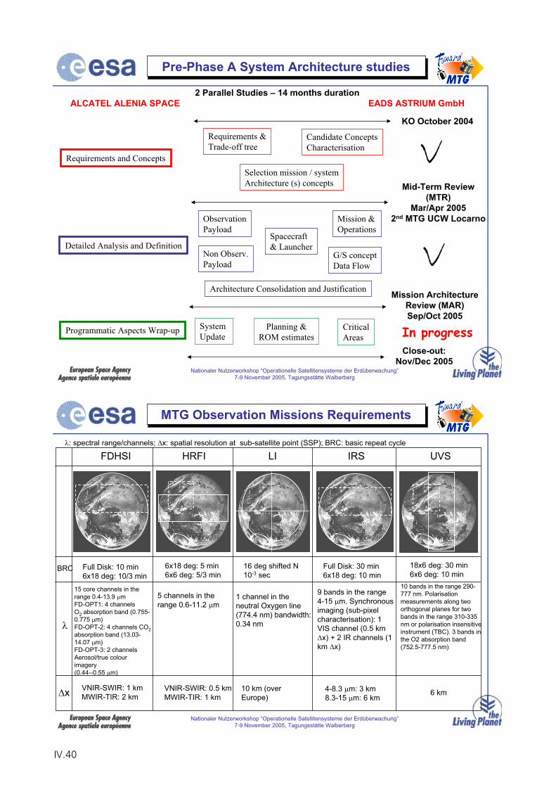
Nationaler Nutzerworkshop “Operationelle Satellitensysteme der Erdüberwachung”7-9 November 2005, Tagungsstätte Walberberg
Pre-Phase A System Architecture studies
Mid-Term Review (MTR)
Mar/Apr 20052nd MTG UCW Locarno
Mission Architecture Review (MAR)Sep/Oct 2005
KO October 2004
Programmatic Aspects Wrap-up System Update
Planning &ROM estimates
CriticalAreas
Close-out:Nov/Dec 2005
Detailed Analysis and Definition
ObservationPayload
Non Observ.Payload
Spacecraft& Launcher
Mission &Operations
G/S conceptData Flow
Architecture Consolidation and Justification
Requirements and Concepts
Requirements &Trade-off tree
Candidate ConceptsCharacterisation
Selection mission / systemArchitecture (s) concepts
2 Parallel Studies – 14 months durationALCATEL ALENIA SPACE EADS ASTRIUM GmbH
v
vIn progress
Nationaler Nutzerworkshop “Operationelle Satellitensysteme der Erdüberwachung”7-9 November 2005, Tagungsstätte Walberberg
MTG Observation Missions Requirements
FDHSI HRFI LI IRS UVS
BRC
x
Full Disk: 10 min6x18 deg: 10/3 min
6x18 deg: 5 min6x6 deg: 5/3 min
16 deg shifted N10-3 sec
Full Disk: 30 min6x18 deg: 10 min
18x6 deg: 30 min6x6 deg: 10 min
15 core channels in the range 0.4-13.9 mFD-OPT1: 4 channelsO2 absorption band (0.755-0.775 m)FD-OPT-2: 4 channels CO2absorption band (13.03-14.07 m)FD-OPT-3: 2 channels Aerosol/true colour imagery (0.44--0.55 m)
5 channels in the range 0.6-11.2 m
1 channel in the neutral Oxygen line (774.4 nm) bandwidth: 0.34 nm
9 bands in the range 4-15 m. Synchronous imaging (sub-pixel characterisation): 1 VIS channel (0.5 km
x) + 2 IR channels (1 km x)
10 bands in the range 290-777 nm. Polarisation measurements along two orthogonal planes for two bands in the range 310-335 nm or polarisation insensitive instrument (TBC). 3 bands in the O2 absorption band (752.5-777.5 nm)
VNIR-SWIR: 1 kmMWIR-TIR: 2 km
VNIR-SWIR: 0.5 kmMWIR-TIR: 1 km
10 km (over Europe)
4-8.3 m: 3 km8.3-15 m: 6 km
6 km
: spectral range/channels; x: spatial resolution at sub-satellite point (SSP); BRC: basic repeat cycle
IV.40
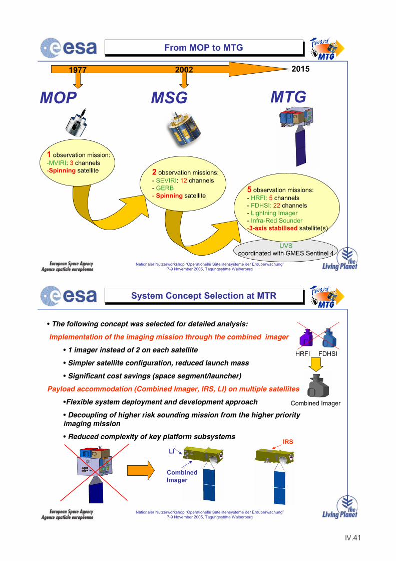
Nationaler Nutzerworkshop “Operationelle Satellitensysteme der Erdüberwachung”7-9 November 2005, Tagungsstätte Walberberg
From MOP to MTG
MTGMSG
1977 20152002
UVScoordinated with GMES Sentinel 4
5 observation missions:- HRFI: 5 channels- FDHSI: 22 channels- Lightning Imager- Infra-Red Sounder-3-axis stabilised satellite(s)
1 observation mission:-MVIRI: 3 channels-Spinning satellite 2 observation missions:
- SEVIRI: 12 channels- GERB- Spinning satellite
MOP
Nationaler Nutzerworkshop “Operationelle Satellitensysteme der Erdüberwachung”7-9 November 2005, Tagungsstätte Walberberg
• The following concept was selected for detailed analysis:
Implementation of the imaging mission through the combined imager
• 1 imager instead of 2 on each satellite
• Simpler satellite configuration, reduced launch mass
• Significant cost savings (space segment/launcher)
Payload accommodation (Combined Imager, IRS, LI) on multiple satellites
•Flexible system deployment and development approach
• Decoupling of higher risk sounding mission from the higher priority imaging mission
• Reduced complexity of key platform subsystemsIRS
CombinedImager
LI
HRFI FDHSI
Combined Imager
System Concept Selection at MTR
IV.41
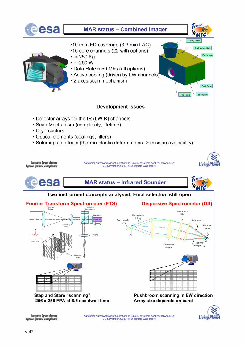
Nationaler Nutzerworkshop “Operationelle Satellitensysteme der Erdüberwachung”7-9 November 2005, Tagungsstätte Walberberg
MAR status – Combined Imager
Baseplate
Earth face
N/S Face
E/W Face
Entry Baffle
Calibration Slot•10 min. FD coverage (3.3 min LAC)•15 core channels (22 with options)• 250 Kg• 250 W• Data Rate 50 Mbs (all options)• Active cooling (driven by LW channels)• 2 axes scan mechanism
Development Issues
• Detector arrays for the IR (LWIR) channels• Scan Mechanism (complexity, lifetime)• Cryo-coolers• Optical elements (coatings, filters)• Solar inputs effects (thermo-elastic deformations -> mission availability)
Nationaler Nutzerworkshop “Operationelle Satellitensysteme der Erdüberwachung”7-9 November 2005, Tagungsstätte Walberberg
MAR status – Infrared Sounder
opd = time
TelescopeOptics
Michelsoninterferometer
Imagingoptics
Collimatingoptics
Detectorarray
Mecanism
Spectralsample 0
Wavelength0
Slit
Wavelength0
Dispersivesystem
Detectorarray
Band-passfilter
Cold stop
Two instrument concepts analysed. Final selection still open
Fourier Transform Spectrometer (FTS) Dispersive Spectrometer (DS)
Step and Stare “scanning” Pushbroom scanning in EW direction256 x 256 FPA at 6.5 sec dwell time Array size depends on band
IV.42
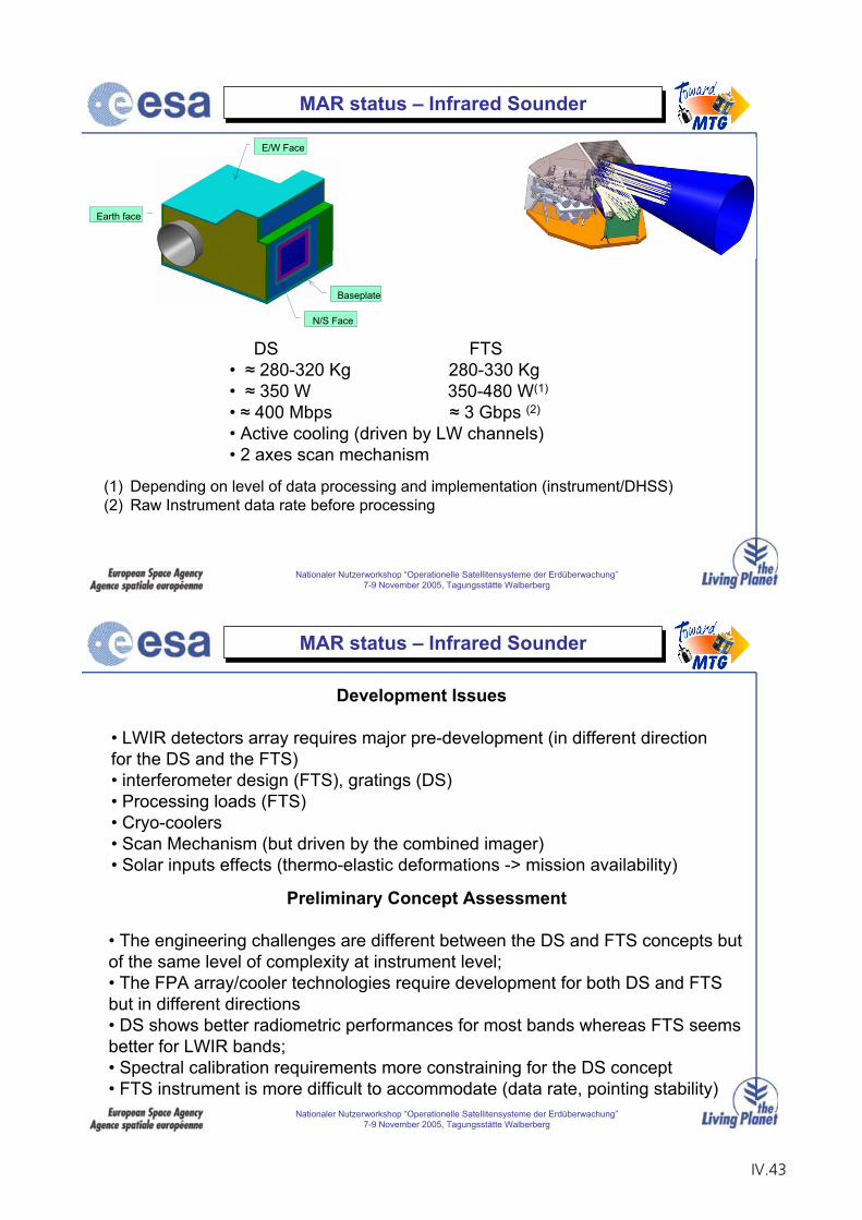
Nationaler Nutzerworkshop “Operationelle Satellitensysteme der Erdüberwachung”7-9 November 2005, Tagungsstätte Walberberg
MAR status – Infrared Sounder
Baseplate
Earth face
N/S Face
E/W Face
DS FTS• 280-320 Kg 280-330 Kg• 350 W 350-480 W(1)
• 400 Mbps 3 Gbps (2)
• Active cooling (driven by LW channels)• 2 axes scan mechanism
(1) Depending on level of data processing and implementation (instrument/DHSS)(2) Raw Instrument data rate before processing
Nationaler Nutzerworkshop “Operationelle Satellitensysteme der Erdüberwachung”7-9 November 2005, Tagungsstätte Walberberg
MAR status – Infrared Sounder
Development Issues
• LWIR detectors array requires major pre-development (in different direction for the DS and the FTS)• interferometer design (FTS), gratings (DS)• Processing loads (FTS)• Cryo-coolers • Scan Mechanism (but driven by the combined imager)• Solar inputs effects (thermo-elastic deformations -> mission availability)
Preliminary Concept Assessment
• The engineering challenges are different between the DS and FTS concepts but of the same level of complexity at instrument level;• The FPA array/cooler technologies require development for both DS and FTS but in different directions• DS shows better radiometric performances for most bands whereas FTS seems better for LWIR bands;• Spectral calibration requirements more constraining for the DS concept• FTS instrument is more difficult to accommodate (data rate, pointing stability)
IV.43
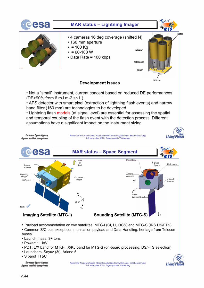
Nationaler Nutzerworkshop “Operationelle Satellitensysteme der Erdüberwachung”7-9 November 2005, Tagungsstätte Walberberg
MAR status – Lightning Imager
radiator
baffle
telescope
prox. el.
bench
radiator
baffle
telescope
prox. el.
bench
• 4 cameras 16 deg coverage (shifted N)• 160 mm aperture• 100 Kg• 60-100 W• Data Rate 100 kbps
Development Issues
• Not a “small” instrument, current concept based on reduced DE performances (DE>90% from 6 mJ.m-2.sr-1 )• APS detector with smart pixel (extraction of lightning flash events) and narrow band filter (160 mm) are technologies to be developed• Lightning flash models (at signal level) are essential for assessing the spatial and temporal coupling of the flash event with the detection process. Different assumptions have a significant impact on the instrument sizing
Nationaler Nutzerworkshop “Operationelle Satellitensysteme der Erdüberwachung”7-9 November 2005, Tagungsstätte Walberberg
MAR status – Space Segment
Combined Imager
LightningImager
UHF patch
L-band antenna
North or
South
Earth
Xs
Zs
Ys
Xs
Zs
Ys
IR-Sounder
X-BandAntenna
S-BandAntenna
XNadirLaunch Direction
DeepSpace
Y
Z
Main Body
Imaging Satellite (MTG-I) Sounding Satellite (MTG-S)
• Payload accommodation on two satellites: MTG-I (CI, LI, DCS) and MTG-S (IRS DS/FTS)• Common S/C bus except communication payload and Data Handling, heritage from Telecom buses• Launch mass: 3+ tons• Power: 1+ kW• PDT: L/X band for MTG-I, X/Ku band for MTG-S (on-board processing, DS/FTS selection)• Launchers: Soyuz (3t), Ariane 5• S band TT&C
IV.44
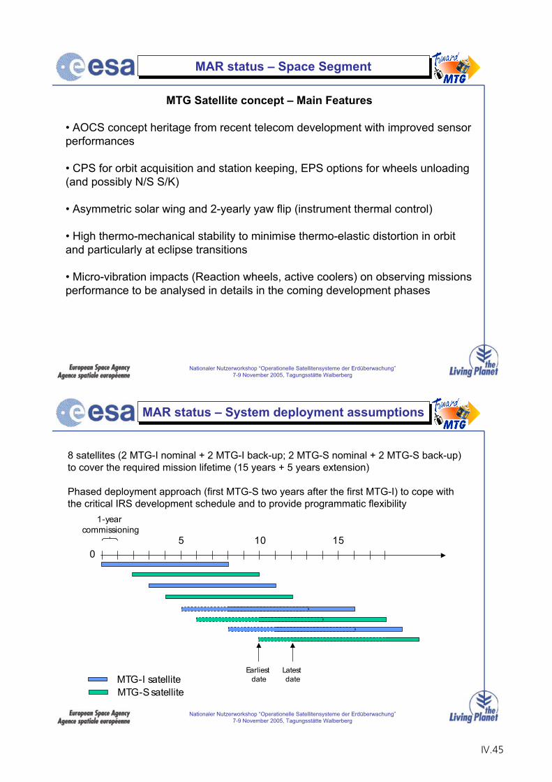
Nationaler Nutzerworkshop “Operationelle Satellitensysteme der Erdüberwachung”7-9 November 2005, Tagungsstätte Walberberg
MAR status – Space Segment
MTG Satellite concept – Main Features
• AOCS concept heritage from recent telecom development with improved sensor performances
• CPS for orbit acquisition and station keeping, EPS options for wheels unloading (and possibly N/S S/K)
• Asymmetric solar wing and 2-yearly yaw flip (instrument thermal control)
• High thermo-mechanical stability to minimise thermo-elastic distortion in orbit and particularly at eclipse transitions
• Micro-vibration impacts (Reaction wheels, active coolers) on observing missions performance to be analysed in details in the coming development phases
Nationaler Nutzerworkshop “Operationelle Satellitensysteme der Erdüberwachung”7-9 November 2005, Tagungsstätte Walberberg
MAR status – System deployment assumptions
50
10 15
MTG-I satelliteMTG-S satellite
1-year commissioning
Earliest date
Latest date
8 satellites (2 MTG-I nominal + 2 MTG-I back-up; 2 MTG-S nominal + 2 MTG-S back-up)to cover the required mission lifetime (15 years + 5 years extension)
Phased deployment approach (first MTG-S two years after the first MTG-I) to cope withthe critical IRS development schedule and to provide programmatic flexibility
IV.45
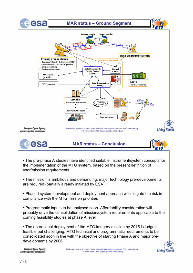
Nationaler Nutzerworkshop “Operationelle Satellitensysteme der Erdüberwachung”7-9 November 2005, Tagungsstätte Walberberg
Real time users
Non real time users
Meteo dataproviders
GOS partners
Primary ground station- Tracking, Telemetry & Command (TTC)- Observation and DCP data acquisition- Level 0 processing- Back-up control centre
Back-up ground station(s)
ArchiveAnd on-line user services
SAF’s- Level 2 processing
Terrestialnetwork
Imager satelliteSounder satellite
0.6 to 1 deg
TT&C (S-band)
ITM (L-band)
ITM (X-band)TT&C (S-band)
ControlCenter
Data Processing & Quality Control
Facility
Data Dissemination Facility
Core facility (Darmstadt)
Real time users
Non real time users
Meteo dataproviders
GOS partners
Primary ground station- Tracking, Telemetry & Command (TTC)- Observation and DCP data acquisition- Level 0 processing- Back-up control centre
Back-up ground station(s)
ArchiveAnd on-line user services
SAF’s- Level 2 processing
Terrestialnetwork
Terrestialnetwork
Imager satelliteSounder satellite
0.6 to 1 deg
TT&C (S-band)
ITM (L-band)
ITM (X-band)TT&C (S-band)
ControlCenter
Data Processing & Quality Control
Facility
Data Dissemination Facility
Core facility (Darmstadt)
MAR status – Ground Segment
Nationaler Nutzerworkshop “Operationelle Satellitensysteme der Erdüberwachung”7-9 November 2005, Tagungsstätte Walberberg
MAR status – Conclusion
• The pre-phase A studies have identified suitable instrument/system concepts for the implementation of the MTG system, based on the present definition of user/mission requirements
• The mission is ambitious and demanding, major technology pre-developments are required (partially already initiated by ESA)
• Phased system development and deployment approach will mitigate the risk in compliance with the MTG mission priorities
• Programmatic inputs to be analysed soon. Affordability consideration will probably drive the consolidation of mission/system requirements applicable to the coming feasibility studies at phase A level
• The operational deployment of the MTG imagery mission by 2015 is judged feasible but challenging. MTG technical and programmatic requirements to be consolidated soon in line with the objective of starting Phase A and major pre-developments by 2006
IV.46
EUMETSAT Activities in Preparation for a Post-EPS System
E. Koenemann
EUMETSAT
IV.47

IV.48
7.-9. November Nationaler NutzerworkshopWallberberg Page 1
Aktuelle und geplante Aktivitäten
zur Vorbereitung des
EPS NachfolgesystemsE.Koenemann
Director Programme Development
7.-9. November Nationaler NutzerworkshopWallberberg Page 2
EUMETSAT Strategic Guidelines for Post-EPS
EUMETSAT will remain committed, as a minimum and top priority, to the mid - morning sounding mission
There is a joint commitment between EUM Member States and NOAAfor a future Polar System (JPS)
Possible EUMETSAT contribution to JPS fully open:
- instruments across the various orbits;- satellites on different orbits; etc.
as long as EUMETSAT keeps responsibility for at least one end-to-end system
IV.49
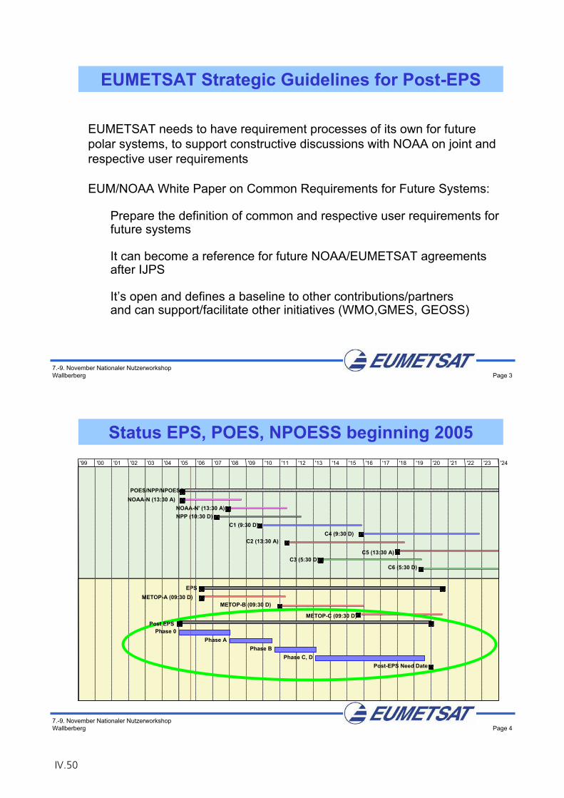
7.-9. November Nationaler NutzerworkshopWallberberg Page 3
EUMETSAT needs to have requirement processes of its own for future polar systems, to support constructive discussions with NOAA on joint andrespective user requirements
EUM/NOAA White Paper on Common Requirements for Future Systems:
Prepare the definition of common and respective user requirements forfuture systems
It can become a reference for future NOAA/EUMETSAT agreementsafter IJPS
It’s open and defines a baseline to other contributions/partners and can support/facilitate other initiatives (WMO,GMES, GEOSS)
EUMETSAT Strategic Guidelines for Post-EPS
7.-9. November Nationaler NutzerworkshopWallberberg Page 4
Status EPS, POES, NPOESS beginning 2005
POES/NPP/NPOESSNOAA-N (13:30 A)
NOAA-N' (13:30 A)NPP (10:30 D)
C1 (9:30 D)C4 (9:30 D)
C2 (13:30 A)
C5 (13:30 A)C3 (5:30 D)
C6 (5:30 D)
EPSMETOP-A (09:30 D)
METOP-B (09:30 D)
METOP-C (09:30 D)
Phase 0Phase A
Phase BPhase C, D
Post-EPS Need Date
'99 '00 '01 '02 '03 '04 '05 '06 '07 '08 '09 '10 '11 '12 '13 '14 '15 '16 '17 '18 '19 '20 '21 '22 '23 '24
Post EPS
IV.50
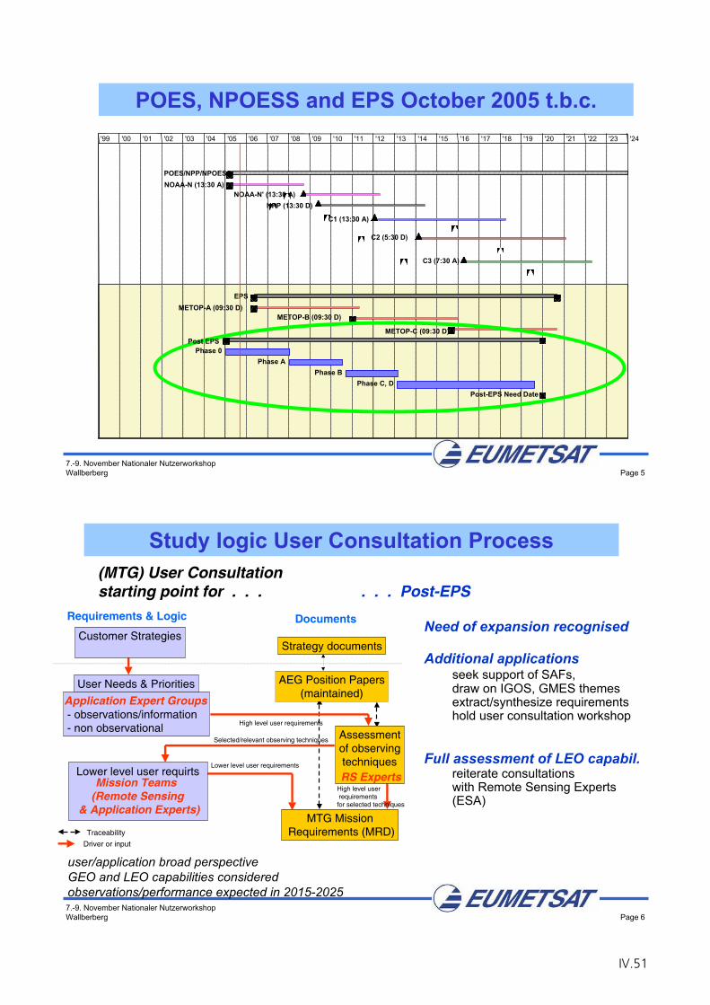
7.-9. November Nationaler NutzerworkshopWallberberg Page 5
POES, NPOESS and EPS October 2005 t.b.c.
POES/NPP/NPOESSNOAA-N (13:30 A)
NOAA-N' (13:30 A)NPP (13:30 D)
C1 (13:30 A)
C2 (5:30 D)
C3 (7:30 A)
EPSMETOP-A (09:30 D)
METOP-B (09:30 D)
METOP-C (09:30 D)
Phase 0Phase A
Phase BPhase C, D
Post-EPS Need Date
'99 '00 '01 '02 '03 '04 '05 '06 '07 '08 '09 '10 '11 '12 '13 '14 '15 '16 '17 '18 '19 '20 '21 '22 '23 '24
Post EPS
7.-9. November Nationaler NutzerworkshopWallberberg Page 6
Lower level user requirements
MTG Mission Requirements (MRD)
High level user requirements for selected techniques
Lower level user requirts
- observations/information- non observational
User Needs & Priorities
Customer Strategies
Requirements & Logic
Driver or input
Traceability
Selected/relevant observing techniques
High level user requirements
RS Experts
Application Expert Groups
Mission Teams (Remote Sensing
& Application Experts)
AEG Position Papers(maintained)
Strategy documents
Documents
Assessmentof observing techniquesRS Experts
(MTG) User Consultation starting point for . . . . . . Post-EPS
user/application broad perspectiveGEO and LEO capabilities consideredobservations/performance expected in 2015-2025
Need of expansion recognised
Additional applications seek support of SAFs, draw on IGOS, GMES themesextract/synthesize requirementshold user consultation workshop
Full assessment of LEO capabil.reiterate consultationswith Remote Sensing Experts(ESA)
Study logic User Consultation Process
IV.51
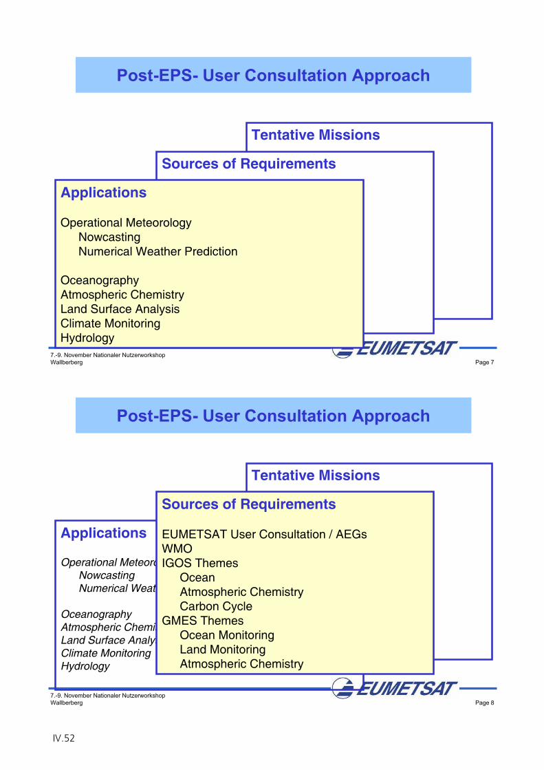
7.-9. November Nationaler NutzerworkshopWallberberg Page 7
Tentative Missions
Atmospheric SoundingAtmospheric ChemistryOcean Imaging
(incl. Sea Ice, Winds)Ocean Surface TopographyCloud & Land Surface Imaging
(incl. Precipitation)Wind Profiling
Sources of Requirements
(MTG) User ConsultationWMOIGOS Themes
OceanAtmospheric Chemistry
GOOSGMES Themes
Ocean MonitoringLand MonitoringAtmospheric Chemistry
Applications
Operational MeteorologyNowcastingNumerical Weather Prediction
OceanographyAtmospheric ChemistryLand Surface AnalysisClimate MonitoringHydrology
Post-EPS- User Consultation Approach
7.-9. November Nationaler NutzerworkshopWallberberg Page 8
Tentative Missions
Atmospheric SoundingAtmospheric ChemistryOcean Imaging
(incl. Sea Ice, Winds)Ocean Surface TopographyCloud & Land Surface Imaging
(incl. Precipitation)Wind Profiling
Applications
Operational MeteorologyNowcastingNumerical Weather Prediction
OceanographyAtmospheric ChemistryLand Surface AnalysisClimate MonitoringHydrology
Sources of Requirements
EUMETSAT User Consultation / AEGsWMOIGOS Themes
OceanAtmospheric ChemistryCarbon Cycle
GMES ThemesOcean MonitoringLand MonitoringAtmospheric Chemistry
Post-EPS- User Consultation Approach
IV.52
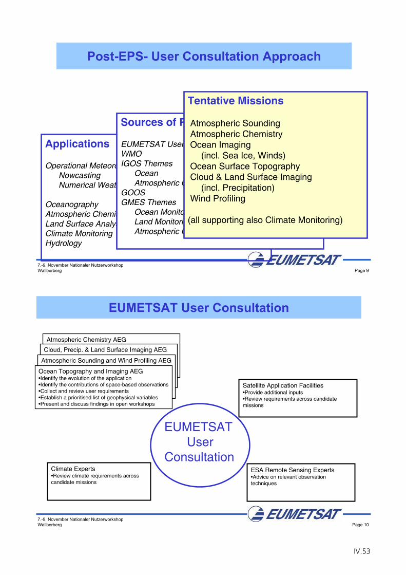
7.-9. November Nationaler NutzerworkshopWallberberg Page 9
Applications
Operational MeteorologyNowcastingNumerical Weather Prediction
OceanographyAtmospheric ChemistryLand Surface AnalysisClimate MonitoringHydrology
Sources of Requirements
EUMETSAT User ConsultationWMOIGOS Themes
OceanAtmospheric Chemistry
GOOSGMES Themes
Ocean MonitoringLand MonitoringAtmospheric Chemistry
Tentative Missions
Atmospheric SoundingAtmospheric ChemistryOcean Imaging
(incl. Sea Ice, Winds)Ocean Surface TopographyCloud & Land Surface Imaging
(incl. Precipitation)Wind Profiling
(all supporting also Climate Monitoring)
Post-EPS- User Consultation Approach
7.-9. November Nationaler NutzerworkshopWallberberg Page 10
Atmospheric Chemistry AEG•Identify the evolution of the application •Identify the contributions of space-based observations•Collect and review user requirements•Establish a prioritised list of geophysical variables•Present and discuss findings in open workshops
Cloud, Precip. & Land Surface Imaging AEG•Identify the evolution of the application •Identify the contributions of space-based observations•Collect and review user requirements•Establish a prioritised list of geophysical variables•Present and discuss findings in open workshops
Atmospheric Sounding and Wind Profiling AEG•Identify the evolution of the application •Identify the contributions of space-based observations•Collect and review user requirements•Establish a prioritised list of geophysical variables•Present and discuss findings in open workshops
EUMETSAT User Consultation
EUMETSATUser
ConsultationClimate Experts•Review climate requirements across candidate missions
Ocean Topography and Imaging AEG•Identify the evolution of the application •Identify the contributions of space-based observations•Collect and review user requirements•Establish a prioritised list of geophysical variables•Present and discuss findings in open workshops
Satellite Application Facilities•Provide additional inputs•Review requirements across candidate missions
ESA Remote Sensing Experts•Advice on relevant observation techniques
IV.53
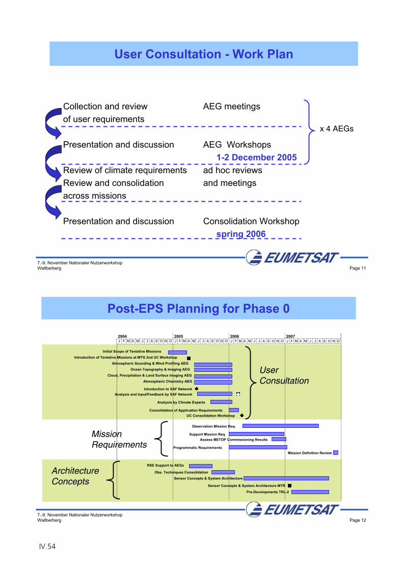
7.-9. November Nationaler NutzerworkshopWallberberg Page 11
Collection and review of user requirements
Presentation and discussion
Review of climate requirementsReview and consolidation across missions
Presentation and discussion
User Consultation - Work Plan
AEG meetings
AEG Workshops1-2 December 2005
ad hoc reviewsand meetings
Consolidation Workshopspring 2006
x 4 AEGs
7.-9. November Nationaler NutzerworkshopWallberberg Page 12
Post-EPS Planning for Phase 0
Initial Scope of Tentative MissionsIntroduction of Tentative Missions at MTG 2nd UC Workshop
Atmospheric Sounding & Wind Profiling AEGOcean Topography & Imaging AEG
Cloud, Precipitation & Land Surface Imaging AEGAtmospheric Chemistry AEG
Consolidation of Application RequirementsUC Consolidation Workshop
Observation Mission Req.
Support Mission Req.Assess METOP Commissioning Results
Programmatic RequirementsMission Definition Review
RSE Support to AEGs
Obs. Techniques ConsolidationSensor Concepts & System Architecture
Sensor Concepts & System Architecture MTR
Pre-Developments TRL-2
J F M A M J J A S O N D J F M A M J J A S O N D J F M A M J J A S O N D J F M A M J J A S O N D2004 2005 2006 2007
UserConsultation
MissionRequirements
ArchitectureConcepts
Introduction to SAF NetworkAnalysis and Input/Feedback by SAF Network
Analysis by Climate Experts
IV.54
7.-9. November Nationaler NutzerworkshopWallberberg Page 13
Co-Ordinated EUMETSAT/ESA positions on MTG, Post-EPS and GMES planning Assumptions EUM/C/57/05/DOC/47
Revised Declaration covering the Earth Observation Envelope Programme
(programme proposal for EOEP-3) ESA/PB-EO(2005)72 rev 2
Earth Observation Envelope Programme, Development and Exploitation Element, Preparation of EUMETSAT missions : MTG and Post-EPS,
Assumption shared with EUMETSAT, status and outlook Information Note
ESA/PB-EO(2005)85
Supporting Documents
IV.55

Chapter V
National Technology Studies
Related to a Future Post-EPS System

The Imaging Radiometer MetImage
Dr. B. Voß
Jena Optronik GmbH
V.1

V.2
METimageDr. B. Voß
1
This
docu
men
t co
nta
ins
info
rmat
ion p
ropriet
ary
to J
ena-
Optr
onik
Gm
bH
. Any
dis
closu
re,
use
or
duplic
ation o
f th
is d
ocu
men
t is
exp
ress
lypro
hib
ited
.
METimage
Walberberg Workshop
07-09 Nov. 2005
METimageDr. B. Voß
2
This
docu
men
t co
nta
ins
info
rmat
ion p
ropriet
ary
to J
ena-
Optr
onik
Gm
bH
. Any
dis
closu
re,
use
or
duplic
ation o
f th
is d
ocu
men
t is
exp
ress
lypro
hib
ited
.
METimage
• General need for AVHRR successorJena-Optronik proposed instrument concept METimage for future operational weather satellites (Polar platforms).Various instrument concepts were established in a METimage study co-financed by DLR.
V.3
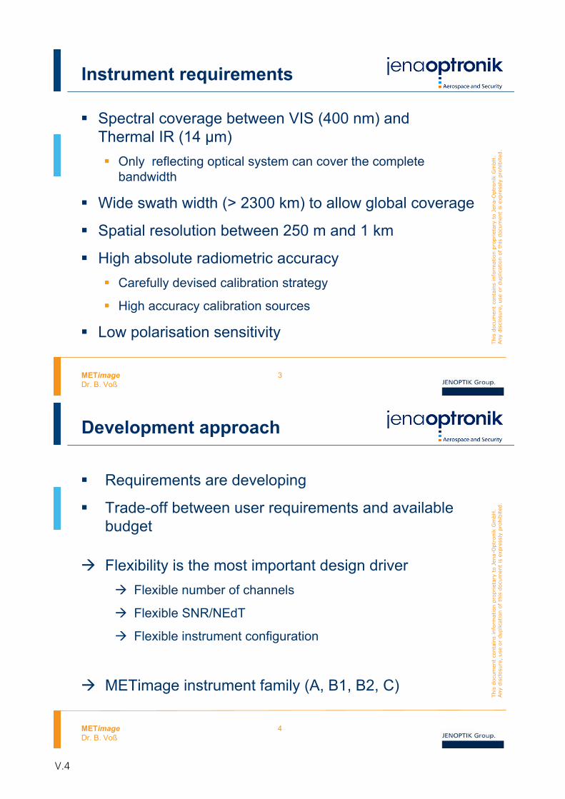
METimageDr. B. Voß
3
This
docu
men
t co
nta
ins
info
rmat
ion p
ropriet
ary
to J
ena-
Optr
onik
Gm
bH
. Any
dis
closu
re,
use
or
duplic
ation o
f th
is d
ocu
men
t is
exp
ress
lypro
hib
ited
.
Instrument requirements
Spectral coverage between VIS (400 nm) and Thermal IR (14 μm)
Only reflecting optical system can cover the completebandwidth
Wide swath width (> 2300 km) to allow global coverage
Spatial resolution between 250 m and 1 km
High absolute radiometric accuracyCarefully devised calibration strategy
High accuracy calibration sources
Low polarisation sensitivity
METimageDr. B. Voß
4
This
docu
men
t co
nta
ins
info
rmat
ion p
ropriet
ary
to J
ena-
Optr
onik
Gm
bH
. Any
dis
closu
re,
use
or
duplic
ation o
f th
is d
ocu
men
t is
exp
ress
lypro
hib
ited
.
Development approach
Requirements are developing
Trade-off between user requirements and available budget
Flexibility is the most important design driver Flexible number of channels
Flexible SNR/NEdT
Flexible instrument configuration
METimage instrument family (A, B1, B2, C)
V.4
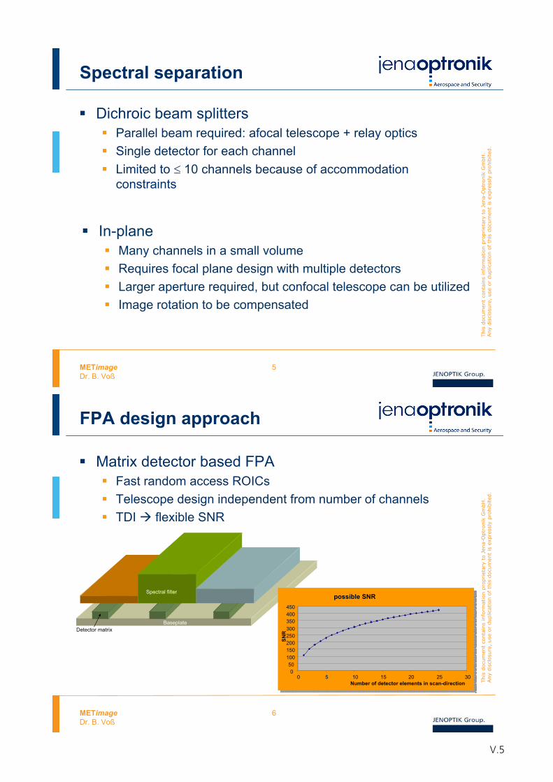
METimageDr. B. Voß
5
This
docu
men
t co
nta
ins
info
rmat
ion p
ropriet
ary
to J
ena-
Optr
onik
Gm
bH
. Any
dis
closu
re,
use
or
duplic
ation o
f th
is d
ocu
men
t is
exp
ress
lypro
hib
ited
.
Spectral separation
Dichroic beam splittersParallel beam required: afocal telescope + relay opticsSingle detector for each channelLimited to 10 channels because of accommodationconstraints
In-planeMany channels in a small volumeRequires focal plane design with multiple detectorsLarger aperture required, but confocal telescope can be utilizedImage rotation to be compensated
METimageDr. B. Voß
6
This
docu
men
t co
nta
ins
info
rmat
ion p
ropriet
ary
to J
ena-
Optr
onik
Gm
bH
. Any
dis
closu
re,
use
or
duplic
ation o
f th
is d
ocu
men
t is
exp
ress
lypro
hib
ited
.
FPA design approach
Matrix detector based FPAFast random access ROICsTelescope design independent from number of channelsTDI flexible SNR
BaseplateDetector matrix
Spectral filterpossible SNR
050
100150200250300350400450
0 5 10 15 20 25 30Number of detector elements in scan-direction
SNR
possible SNR
050
100150200250300350400450
0 5 10 15 20 25 30Number of detector elements in scan-direction
SNR
V.5
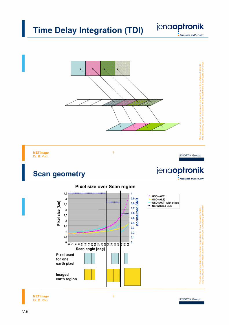
METimageDr. B. Voß
7
This
docu
men
t co
nta
ins
info
rmat
ion p
ropriet
ary
to J
ena-
Optr
onik
Gm
bH
. Any
dis
closu
re,
use
or
duplic
ation o
f th
is d
ocu
men
t is
exp
ress
lypro
hib
ited
.
Time Delay Integration (TDI)
METimageDr. B. Voß
8
This
docu
men
t co
nta
ins
info
rmat
ion p
ropriet
ary
to J
ena-
Optr
onik
Gm
bH
. Any
dis
closu
re,
use
or
duplic
ation o
f th
is d
ocu
men
t is
exp
ress
lypro
hib
ited
.
Pixel usedfor oneearth pixel
Imagedearth region
Pixel size over Scan region
0
0,5
1
1,5
2
2,5
3
3,5
4
4,5
0 3 6 9 12 15 18 21 24 27 30 33 36 39 42 45 48 51 54
Scan angle [deg]
Pixe
l siz
e[k
m]
0
0,1
0,2
0,3
0,4
0,5
0,6
0,7
0,8
0,9
1
norm
aliz
edSN
R
GSD (ACT)GSD (ALT)GSD (ACT) with stepsNormalized SNR
Scan geometry
V.6
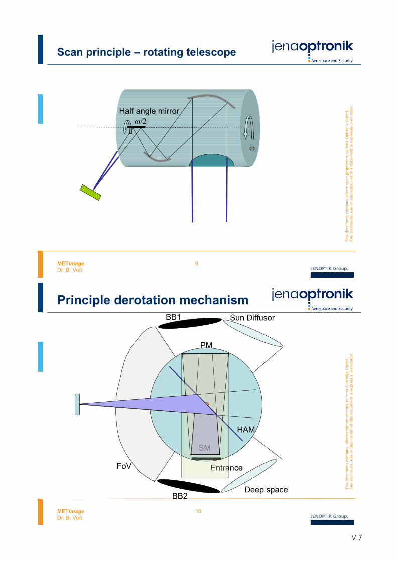
METimageDr. B. Voß
9
This
docu
men
t co
nta
ins
info
rmat
ion p
ropriet
ary
to J
ena-
Optr
onik
Gm
bH
. Any
dis
closu
re,
use
or
duplic
ation o
f th
is d
ocu
men
t is
exp
ress
lypro
hib
ited
.
Half angle mirror
Scan principle – rotating telescope
METimageDr. B. Voß
10
This
docu
men
t co
nta
ins
info
rmat
ion p
ropriet
ary
to J
ena-
Optr
onik
Gm
bH
. Any
dis
closu
re,
use
or
duplic
ation o
f th
is d
ocu
men
t is
exp
ress
lypro
hib
ited
.
FoV
BB1
BB2
Sun Diffusor
Deep space
Entrance
PM
SM
HAM
Entra
SM
Principle derotation mechanism
V.7
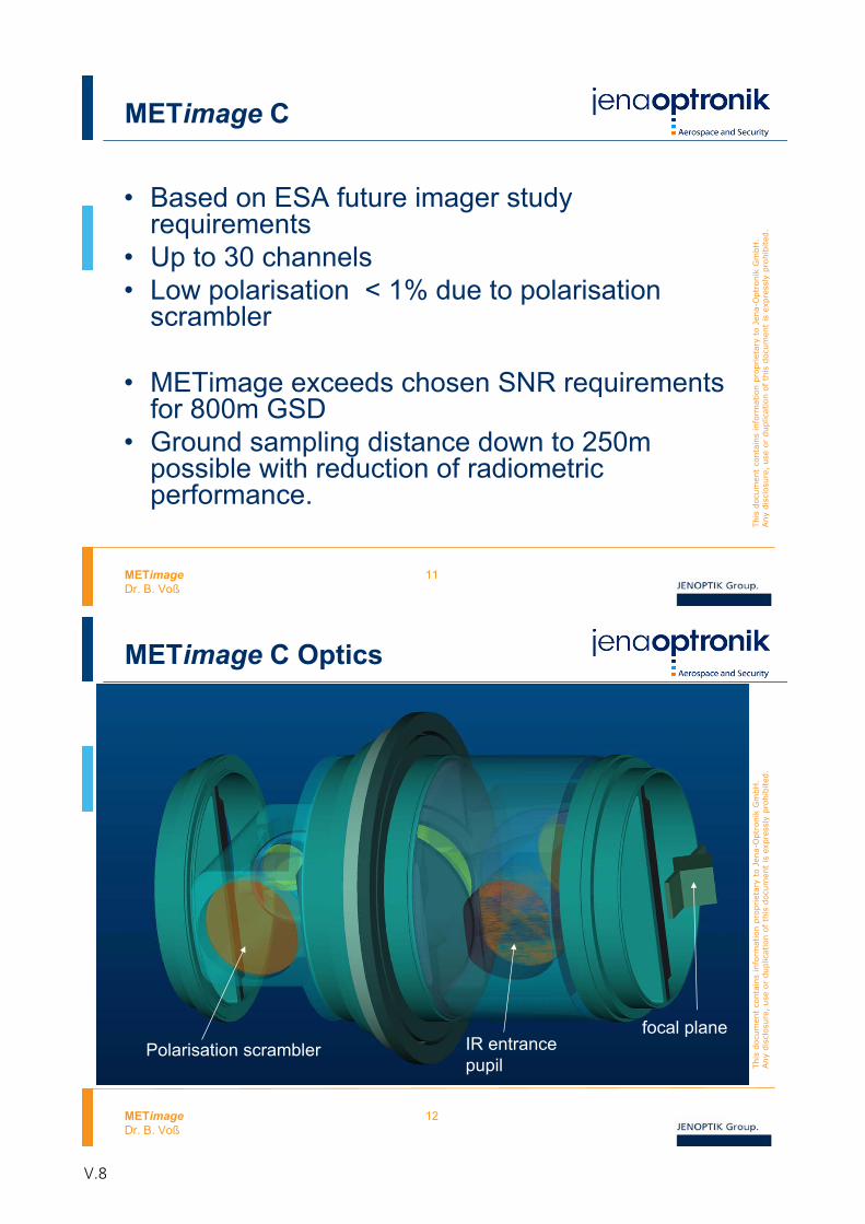
METimageDr. B. Voß
11
This
docu
men
t co
nta
ins
info
rmat
ion p
ropriet
ary
to J
ena-
Optr
onik
Gm
bH
. Any
dis
closu
re,
use
or
duplic
ation o
f th
is d
ocu
men
t is
exp
ress
lypro
hib
ited
.
METimage C
• Based on ESA future imager studyrequirements
• Up to 30 channels• Low polarisation < 1% due to polarisation
scrambler
• METimage exceeds chosen SNR requirementsfor 800m GSD
• Ground sampling distance down to 250m possible with reduction of radiometricperformance.
METimageDr. B. Voß
12
This
docu
men
t co
nta
ins
info
rmat
ion p
ropriet
ary
to J
ena-
Optr
onik
Gm
bH
. Any
dis
closu
re,
use
or
duplic
ation o
f th
is d
ocu
men
t is
exp
ress
lypro
hib
ited
.
METimage C Optics
Polarisation scramblerfocal plane
IR entrancepupil
V.8
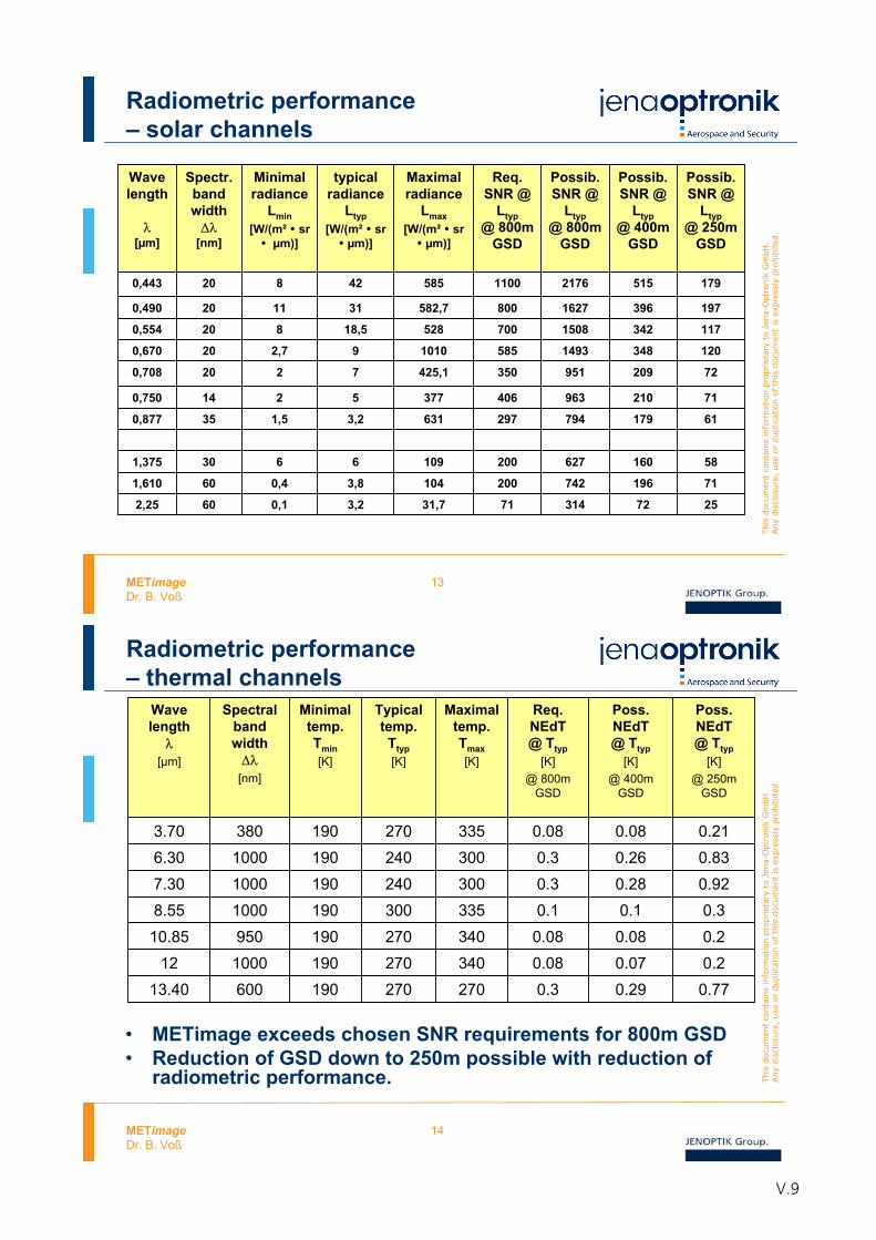
METimageDr. B. Voß
13
This
docu
men
t co
nta
ins
info
rmat
ion p
ropriet
ary
to J
ena-
Optr
onik
Gm
bH
. Any
dis
closu
re,
use
or
duplic
ation o
f th
is d
ocu
men
t is
exp
ress
lypro
hib
ited
.
Radiometric performance– solar channels
Wavelength
[μm]
Spectr.bandwidth
[nm]
Minimalradiance
Lmin[W/(m² sr
μm)]
typical radiance
Ltyp[W/(m² sr
μm)]
Maximalradiance
Lmax[W/(m² sr
μm)]
Req.SNR @
Ltyp@ 800m
GSD
Possib. SNR @
Ltyp@ 800m
GSD
Possib. SNR @
Ltyp@ 400m
GSD
2176 515
396
342
348
209
210
179
160
196
72
1627
1508
1493
951
963
794
627
742
314
1100
800
700
585
350
406
297
200
200
71
Possib. SNR @
Ltyp@ 250m
GSD
0,443 20 8 42 585 179
0,490 20 11 31 582,7 197
0,554 20 8 18,5 528 117
0,670 20 2,7 9 1010 120
0,708 20 2 7 425,1 72
0,750 14 2 5 377 71
0,877 35 1,5 3,2 631 61
1,375 30 6 6 109 58
1,610 60 0,4 3,8 104 71
2,25 60 0,1 3,2 31,7 25
METimageDr. B. Voß
14
This
docu
men
t co
nta
ins
info
rmat
ion p
ropriet
ary
to J
ena-
Optr
onik
Gm
bH
. Any
dis
closu
re,
use
or
duplic
ation o
f th
is d
ocu
men
t is
exp
ress
lypro
hib
ited
.
Radiometric performance– thermal channels
Wavelength
[μm]
Spectralbandwidth
[nm]
Minimaltemp.Tmin[K]
Typical temp.Ttyp[K]
Maximaltemp.Tmax[K]
Req.NEdT@ Ttyp
[K]@ 800m
GSD
Poss.NEdT@ Ttyp
[K]@ 400m
GSD
0.08 0.080.260.280.10.080.070.29
0.30.30.10.080.080.3
Poss.NEdT@ Ttyp
[K]@ 250m
GSD
3.70 380 190 270 335 0.216.30 1000 190 240 300 0.837.30 1000 190 240 300 0.928.55 1000 190 300 335 0.310.85 950 190 270 340 0.2
12 1000 190 270 340 0.213.40 600 190 270 270 0.77
• METimage exceeds chosen SNR requirements for 800m GSD• Reduction of GSD down to 250m possible with reduction of
radiometric performance.
V.9
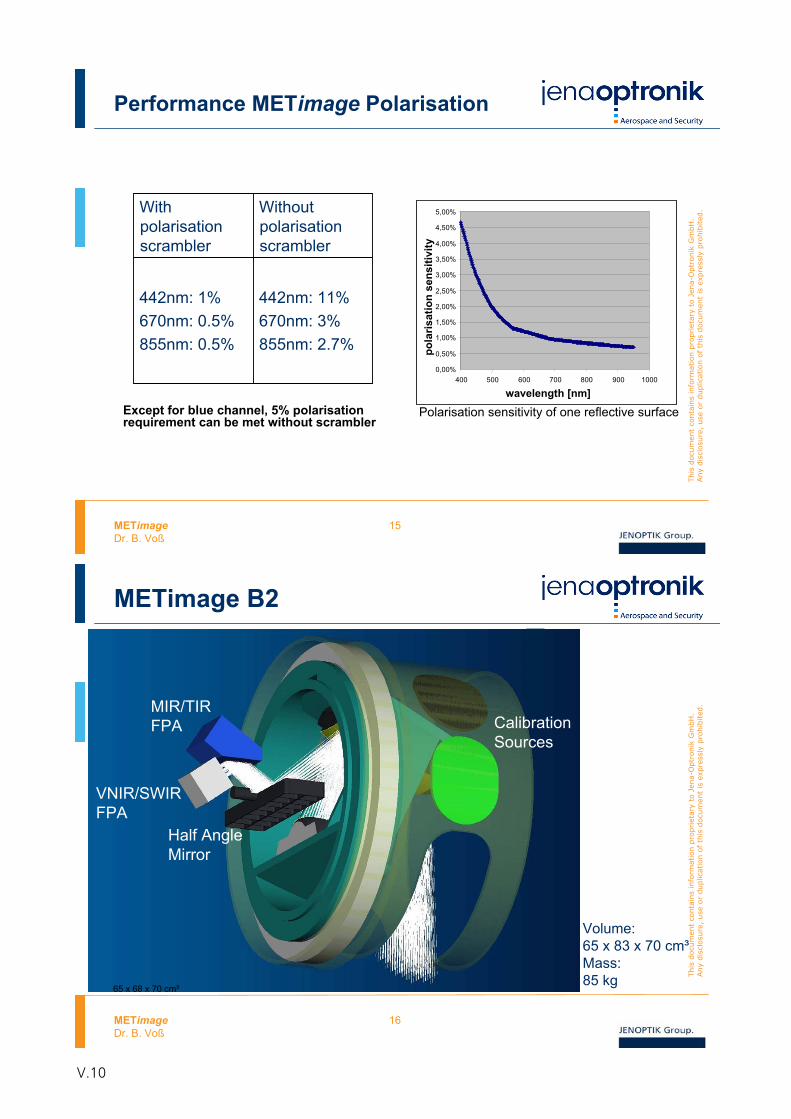
METimageDr. B. Voß
15
This
docu
men
t co
nta
ins
info
rmat
ion p
ropriet
ary
to J
ena-
Optr
onik
Gm
bH
. Any
dis
closu
re,
use
or
duplic
ation o
f th
is d
ocu
men
t is
exp
ress
lypro
hib
ited
.
Performance METimage Polarisation
0,00%
0,50%
1,00%
1,50%
2,00%
2,50%
3,00%
3,50%
4,00%
4,50%
5,00%
400 500 600 700 800 900 1000
wavelength [nm]
pola
risat
ion
sens
itivi
tyPolarisation sensitivity of one reflective surface
Withpolarisationscrambler
Withoutpolarisationscrambler
442nm: 1%670nm: 0.5%855nm: 0.5%
442nm: 11%670nm: 3%855nm: 2.7%
Except for blue channel, 5% polarisationrequirement can be met without scrambler
METimageDr. B. Voß
16
This
docu
men
t co
nta
ins
info
rmat
ion p
ropriet
ary
to J
ena-
Optr
onik
Gm
bH
. Any
dis
closu
re,
use
or
duplic
ation o
f th
is d
ocu
men
t is
exp
ress
lypro
hib
ited
.
METimage B2
Volume:65 x 83 x 70 cm³Mass:85 kg
CalibrationSources
MIR/TIRFPA
VNIR/SWIRFPA
Half Angle Mirror
65 x 68 x 70 cm³
V.10
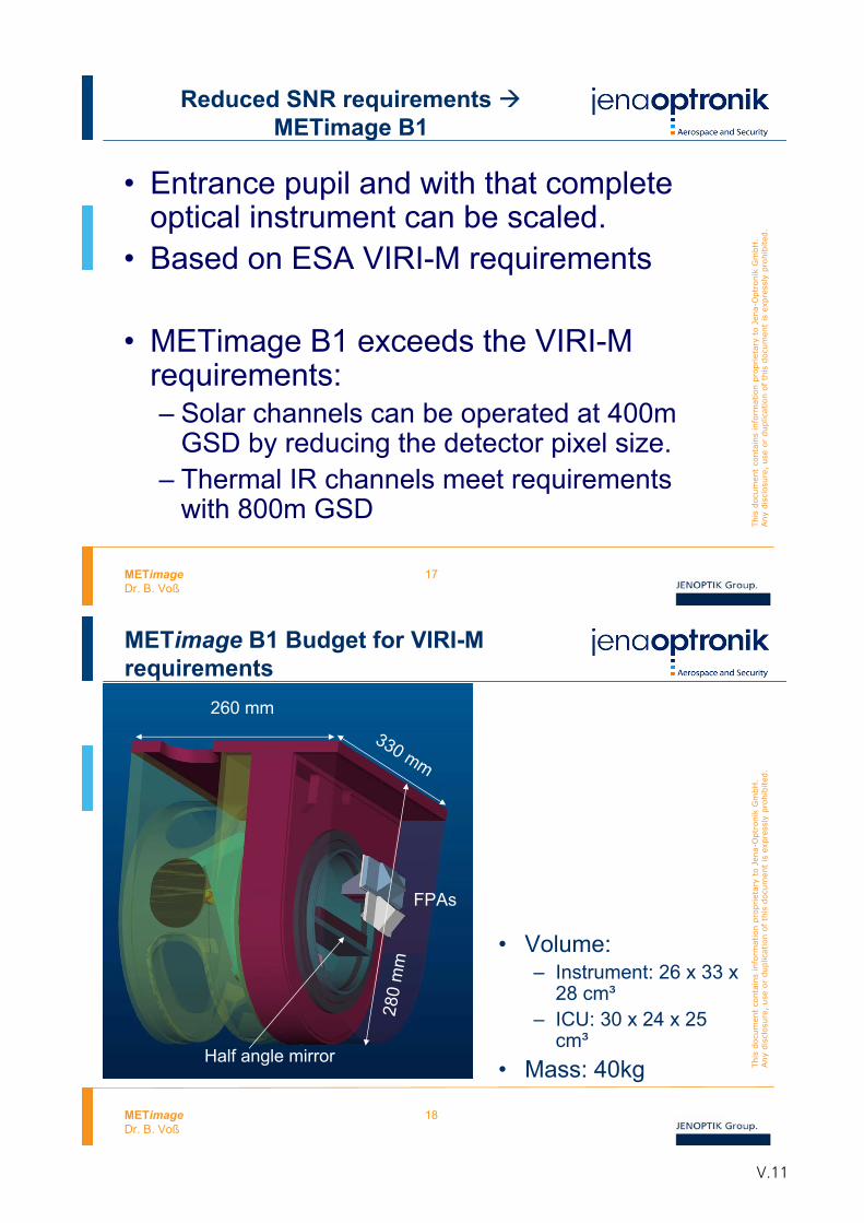
METimageDr. B. Voß
17
This
docu
men
t co
nta
ins
info
rmat
ion p
ropriet
ary
to J
ena-
Optr
onik
Gm
bH
. Any
dis
closu
re,
use
or
duplic
ation o
f th
is d
ocu
men
t is
exp
ress
lypro
hib
ited
.
Reduced SNR requirements METimage B1
• Entrance pupil and with that complete optical instrument can be scaled.
• Based on ESA VIRI-M requirements
• METimage B1 exceeds the VIRI-M requirements:– Solar channels can be operated at 400m
GSD by reducing the detector pixel size.– Thermal IR channels meet requirements
with 800m GSD
METimageDr. B. Voß
18
This
docu
men
t co
nta
ins
info
rmat
ion p
ropriet
ary
to J
ena-
Optr
onik
Gm
bH
. Any
dis
closu
re,
use
or
duplic
ation o
f th
is d
ocu
men
t is
exp
ress
lypro
hib
ited
.
METimage B1 Budget for VIRI-M requirements
• Volume: – Instrument: 26 x 33 x
28 cm³– ICU: 30 x 24 x 25
cm³• Mass: 40kg
330 mm
260 mm
280
mm
Half angle mirror
FPAs
V.11
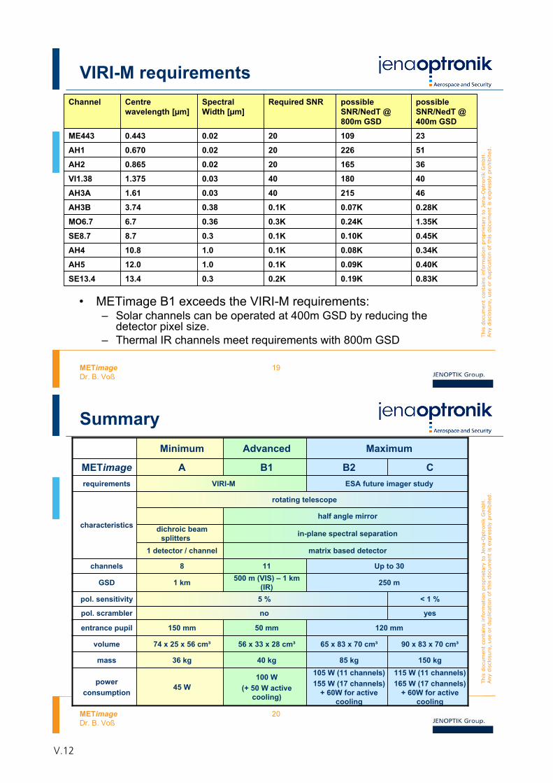
METimageDr. B. Voß
19
This
docu
men
t co
nta
ins
info
rmat
ion p
ropriet
ary
to J
ena-
Optr
onik
Gm
bH
. Any
dis
closu
re,
use
or
duplic
ation o
f th
is d
ocu
men
t is
exp
ress
lypro
hib
ited
.
VIRI-M requirements
• METimage B1 exceeds the VIRI-M requirements:– Solar channels can be operated at 400m GSD by reducing the
detector pixel size.– Thermal IR channels meet requirements with 800m GSD
Channel Centrewavelength [μm]
SpectralWidth [μm]
Required SNR possibleSNR/NedT @ 800m GSD
possibleSNR/NedT @ 400m GSD
ME443 0.443 0.02 20 109
226
165
180
215
0.07K
0.24K
0.10K
0.08K
0.09K
0.19K
23
AH1 0.670 0.02 20 51
AH2 0.865 0.02 20 36
VI1.38 1.375 0.03 40 40
AH3A 1.61 0.03 40 46
AH3B 3.74 0.38 0.1K 0.28K
MO6.7 6.7 0.36 0.3K 1.35K
SE8.7 8.7 0.3 0.1K 0.45K
AH4 10.8 1.0 0.1K 0.34K
AH5 12.0 1.0 0.1K 0.40K
SE13.4 13.4 0.3 0.2K 0.83K
METimageDr. B. Voß
20
This
docu
men
t co
nta
ins
info
rmat
ion p
ropriet
ary
to J
ena-
Optr
onik
Gm
bH
. Any
dis
closu
re,
use
or
duplic
ation o
f th
is d
ocu
men
t is
exp
ress
lypro
hib
ited
.
SummaryMinimum Advanced Maximum
METimagerequirements VIRI-M ESA future imager study
GSD 1 km 500 m (VIS) – 1 km (IR) 250 m
pol. scrambler no yes
entrance pupil 150 mm 50 mm 120 mm
dichroic beam splitters in-plane spectral separation
rotating telescope
half angle mirrorcharacteristics
1 detector / channel matrix based detector
pol. sensitivity 5 % < 1 %
8 11 Up to 30
A B1 B2 C
channels
volume 74 x 25 x 56 cm³ 56 x 33 x 28 cm³ 65 x 83 x 70 cm³
40 kgmass 36 kg
100 W(+ 50 W active
cooling)
90 x 83 x 70 cm³
150 kg115 W (11 channels)165 W (17 channels)
+ 60W for active cooling
85 kg
powerconsumption
45 W
105 W (11 channels)155 W (17 channels)
+ 60W for active cooling
V.12
Concept for a Low-Cost EPS-Gapfiller
Dr. H. Lübberstedt OHB System AG
V.13

V.14
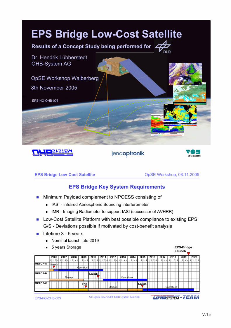
EPS Bridge Low-Cost Satellite
OpSE Workshop Walberberg
8th November 2005
EPS-HO-OHB-003
Results of a Concept Study being performed for
Dr. Hendrik LübberstedtOHB-System AG
All Rights reserved © OHB System AG 2005
EPS Bridge Low-Cost Satellite OpSE Workshop, 08.11.2005
EPS-HO-OHB-003
EPS Bridge Key System Requirements
Minimum Payload complement to NPOESS consisting of IASI - Infrared Atmospheric Sounding Interferometer
IMR - Imaging Radiometer to support IASI (successor of AVHRR)
Low-Cost Satellite Platform with best possible compliance to existing EPS G/S - Deviations possible if motivated by cost-benefit analysisLifetime 3 - 5 years
Nominal launch late 20195 years Storage
2006 2007 2008 2009 2010 2011 2012 2013 2014 2015 2016 2017 2018 2019 20201 2 3 4 1 2 3 4 1 2 3 4 1 2 3 4 1 2 3 4 1 2 3 4 1 2 3 4 1 2 3 4 1 2 3 4 1 2 3 4 1 2 3 4 1 2 3 4 1 2 3 4 1 2 3 4 1 2 3 4
METOP-A
METOP-B
METOP-C FAR LaunchOperationsStorage
LaunchOperations
LaunchOperationsStorage
EPS-BridgeLaunch
V.15
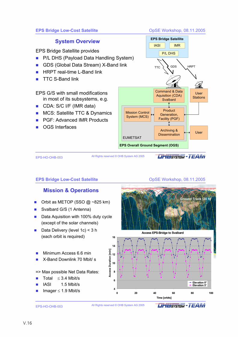
All Rights reserved © OHB System AG 2005
EPS Bridge Low-Cost Satellite OpSE Workshop, 08.11.2005
EPS-HO-OHB-003
System Overview
EPS Bridge Satellite providesP/L DHS (Payload Data Handling System)GDS (Global Data Stream) X-Band linkHRPT real-time L-Band linkTTC S-Band link
EPS Overall Ground Segment (OGS)
EUMETSAT
EPS Bridge Satellite
TTC GDS
Command & DataAquisition (CDA)
Svalbard
IASI IMR
HRPT
UserStations
ProductGeneration,
Facility (PGF)
Mission ControlSystem (MCS)
Archiving &Dissemination User
P/L DHS
EPS G/S with small modifications in most of its subsystems, e.g.CDA: S/C I/F (IMR data)MCS: Satellite TTC & DynamicsPGF: Advanced IMR Products OGS Interfaces
All Rights reserved © OHB System AG 2005
EPS Bridge Low-Cost Satellite OpSE Workshop, 08.11.2005
EPS-HO-OHB-003
Mission & Operations
Orbit as METOP (SSO @ ~825 km)
Svalbard G/S (1 Antenna)
Data Aquisition with 100% duty cycle(except of the solar channels)
Data Delivery (level 1c) < 3 h (each orbit is required)
Ground Track (24 h)
Access EPS-Bridge to Svalbard
4
6
8
10
12
14
16
0 20 40 60 80 100
Time [orbits]
Acc
ess
Dur
atio
n [m
in]
Elevation 0°Elevation 5°
Minimum Access 6.6 minX-Band Downlink 70 Mbit/ s
=> Max possible Net Data Rates:Total 3.4 Mbit/sIASI 1.5 Mbit/sImager 1.9 Mbit/s
V.16
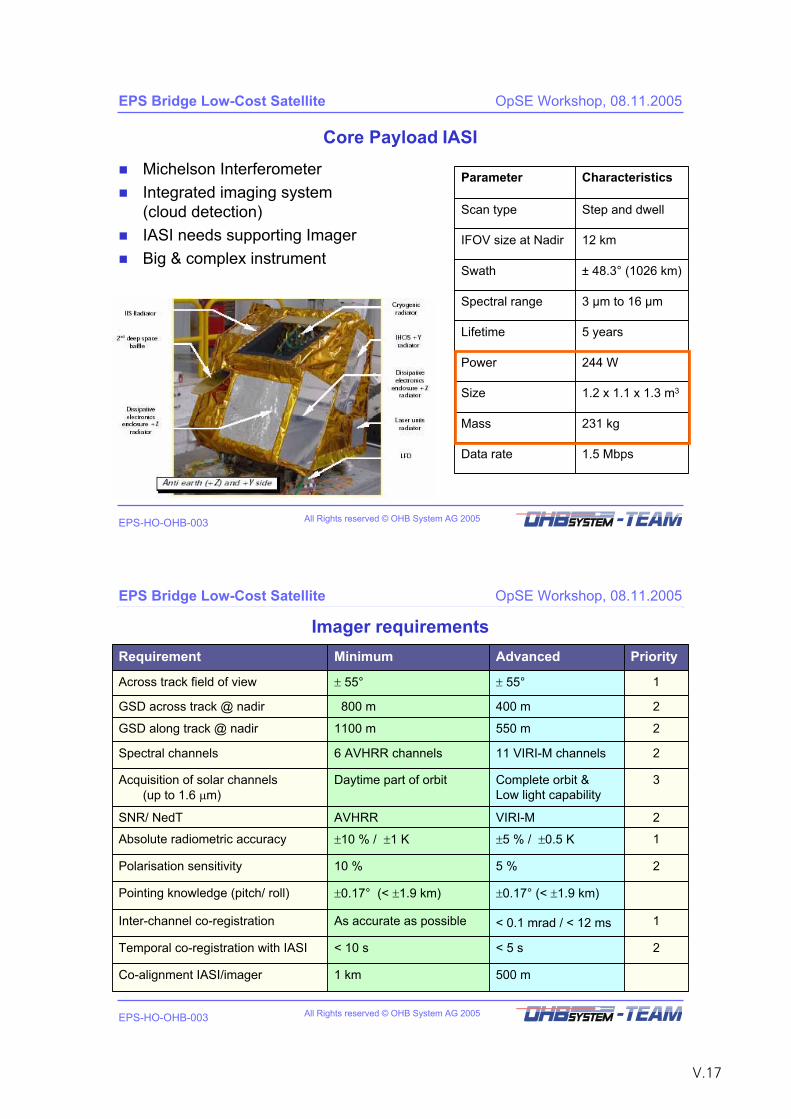
All Rights reserved © OHB System AG 2005
EPS Bridge Low-Cost Satellite OpSE Workshop, 08.11.2005
EPS-HO-OHB-003
Core Payload IASI
Parameter Characteristics
Scan type Step and dwell
IFOV size at Nadir 12 km
Swath ± 48.3° (1026 km)
Spectral range 3 μm to 16 μm
Lifetime 5 years
Power 244 W
Size 1.2 x 1.1 x 1.3 m3
Mass 231 kg
Data rate 1.5 Mbps
Michelson InterferometerIntegrated imaging system(cloud detection)IASI needs supporting ImagerBig & complex instrument
All Rights reserved © OHB System AG 2005
EPS Bridge Low-Cost Satellite OpSE Workshop, 08.11.2005
EPS-HO-OHB-003
Imager requirementsRequirement Minimum Advanced Priority
Across track field of view 55° 55° 1
GSD across track @ nadir 800 m 400 m 2
GSD along track @ nadir 1100 m 550 m 2
Spectral channels 6 AVHRR channels 11 VIRI-M channels 2
Acquisition of solar channels (up to 1.6 m)
Daytime part of orbit Complete orbit &Low light capability
3
SNR/ NedT AVHRR VIRI-M 2
Polarisation sensitivity 10 % 5 % 2
Pointing knowledge (pitch/ roll) 0.17° (< 1.9 km) 0.17° (< 1.9 km)
Inter-channel co-registration As accurate as possible < 0.1 mrad / < 12 ms 1
Temporal co-registration with IASI < 10 s < 5 s 2
Co-alignment IASI/imager 1 km 500 m
Absolute radiometric accuracy 10 % / 1 K 5 % / 0.5 K 1
V.17
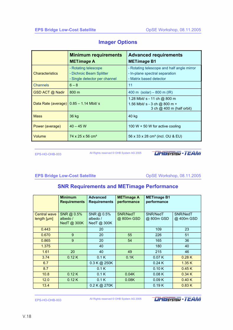
All Rights reserved © OHB System AG 2005
EPS Bridge Low-Cost Satellite OpSE Workshop, 08.11.2005
EPS-HO-OHB-003
Imager Options
Minimum requirementsMETimage A
Advanced requirementsMETimage B1
• Rotating telescope• Dichroic Beam Splitter• Single detector per channel
• Rotating telescope and half angle mirror• In-plane spectral separation• Matrix based detector
Channels 6 – 8 11
Mass 36 kg 40 kg
Power (average) 40 – 45 W 100 W + 50 W for active cooling
Volume 74 x 25 x 56 cm³ 56 x 33 x 28 cm³ (incl. OU & EU)
GSD ACT @ Nadir 800 m 400 m (solar) – 800 m (IR)
Characteristics
Data Rate (average) 0.85 – 1.14 Mbit/ s1.28 Mbit/ s - 11 ch @ 800 m1.56 Mbit/ s - 3 ch @ 800 m +
3 ch @ 400 m (half orbit)
All Rights reserved © OHB System AG 2005
EPS Bridge Low-Cost Satellite OpSE Workshop, 08.11.2005
EPS-HO-OHB-003
SNR Requirements and METimage Performance
MinimumRequirements
AdvancedRequirements
METimage A performance
METimage B1 performance
SNR/NedT@ 800m GSD
5554
490.1K
0.04K0.08K
Central wave length [μm]
SNR @ 0.5% albedo / NedT @ 300K
SNR @ 0.5% albedo / NedT @ 300K
SNR/NedT@ 800m GSD
SNR/NedT@ 400m GSD
0.443 20 109 230.670 9 20 226 510.865 9 20 165 361.375 40 180 401.61 20 40 215 463.74 0.12 K 0.1 K 0.07 K 0.28 K6.7 0.3 K @ 250K 0.24 K 1.35 K8.7 0.1 K 0.10 K 0.45 K10.8 0.12 K 0.1 K 0.08 K 0.34 K12.0 0.12 K 0.1 K 0.09 K 0.40 K13.4 0.2 K @ 270K 0.19 K 0.83 K
V.18
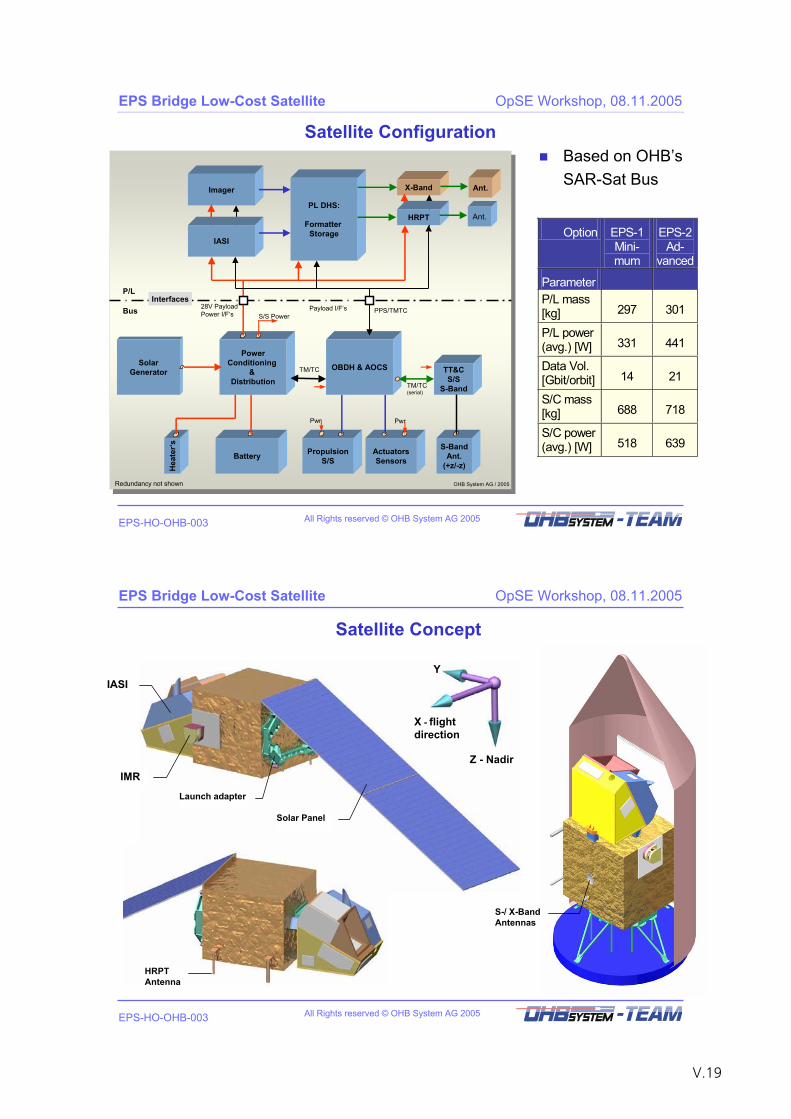
All Rights reserved © OHB System AG 2005
EPS Bridge Low-Cost Satellite OpSE Workshop, 08.11.2005
EPS-HO-OHB-003
Satellite Configuration
OHB System AG / 2005OHB System AG / 2005
SolarGenerator
PowerConditioning
&Distribution
Battery
TT&CS/S
S-Band
S-BandAnt.
(+z/-z)
ActuatorsSensors
PropulsionS/S
S/S Power
Hea
ter‘s
TM/TC(serial)
Payload I/F‘s
Pwr
28V PayloadPower I/F‘s
Imager
P/L
BusInterfaces
Redundancy not shown
PPS/TMTC
OBDH & AOCSTM/TC
Pwr
IASI
PL DHS:
Formatter Storage
X-Band Ant.
Ant.HRPT
Based on OHB’sSAR-Sat Bus
Option EPS-1 Mini-mum
EPS-2 Ad-
vanced
ParameterP/L mass [kg] 297 301
P/L power (avg.) [W] 331 441
Data Vol. [Gbit/orbit] 14 21
S/C mass [kg] 688 718
S/C power (avg.) [W] 518 639
All Rights reserved © OHB System AG 2005
EPS Bridge Low-Cost Satellite OpSE Workshop, 08.11.2005
EPS-HO-OHB-003
Solar Panel
Launch adapter
IASI
IMR
Satellite Concept
HRPTAntenna
S-/ X-Band Antennas
Z - Nadir
X - flightdirection
Y
V.19
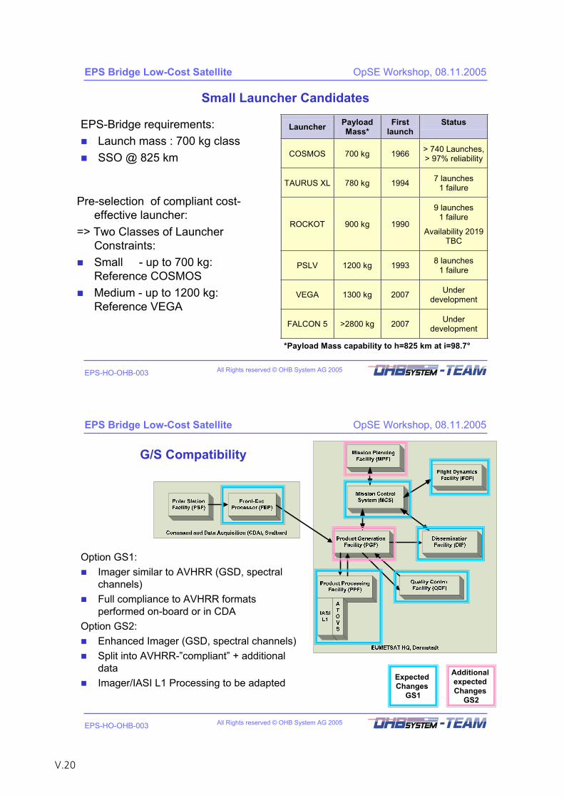
All Rights reserved © OHB System AG 2005
EPS Bridge Low-Cost Satellite OpSE Workshop, 08.11.2005
EPS-HO-OHB-003
Small Launcher Candidates
EPS-Bridge requirements: Launch mass : 700 kg classSSO @ 825 km
Launcher Payload Mass*
Firstlaunch
Status
COSMOS 700 kg 1966 > 740 Launches, > 97% reliability
TAURUS XL 780 kg 1994 7 launches 1 failure
ROCKOT 900 kg 1990
9 launches 1 failure
Availability 2019 TBC
PSLV 1200 kg 1993 8 launches 1 failure
VEGA 1300 kg 2007 Under development
FALCON 5 >2800 kg 2007 Under development
*Payload Mass capability to h=825 km at i=98.7°
Pre-selection of compliant cost-effective launcher:
=> Two Classes of Launcher Constraints:Small - up to 700 kg: Reference COSMOSMedium - up to 1200 kg: Reference VEGA
All Rights reserved © OHB System AG 2005
EPS Bridge Low-Cost Satellite OpSE Workshop, 08.11.2005
EPS-HO-OHB-003
G/S Compatibility
Option GS1: Imager similar to AVHRR (GSD, spectral channels)Full compliance to AVHRR formats performed on-board or in CDA
Option GS2:Enhanced Imager (GSD, spectral channels)Split into AVHRR-”compliant” + additional dataImager/IASI L1 Processing to be adapted Expected
ChangesGS1
Additional expectedChanges
GS2
V.20
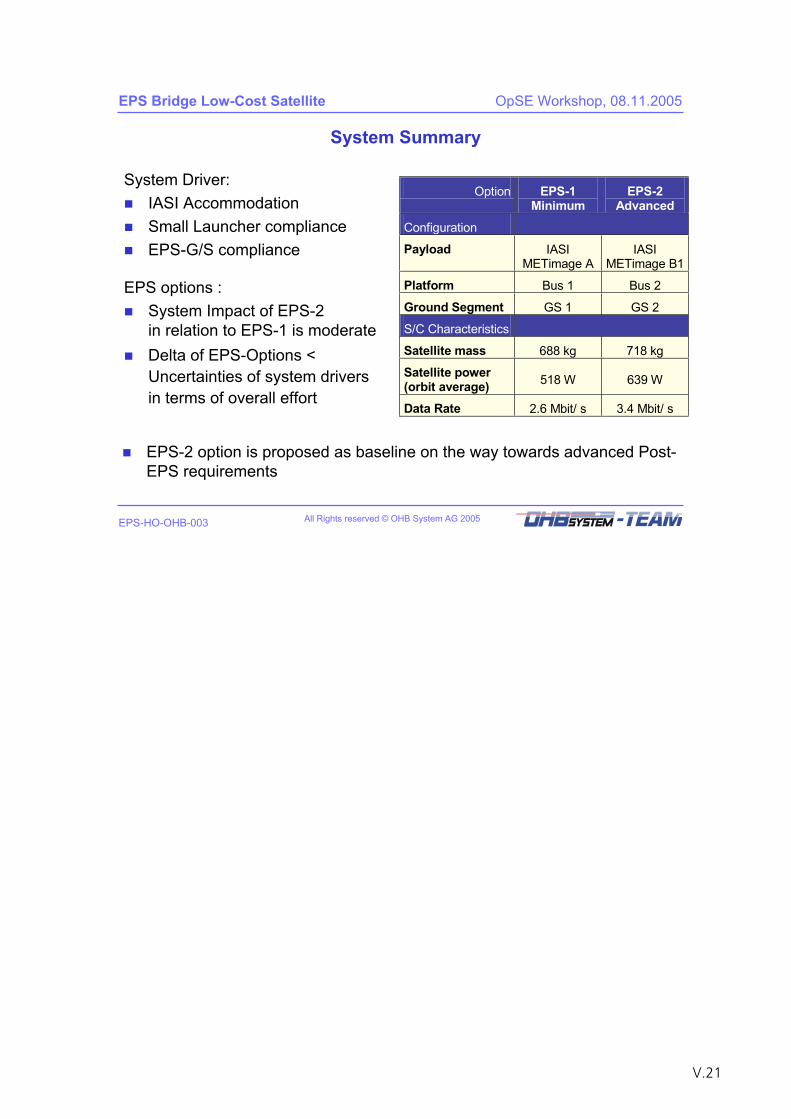
All Rights reserved © OHB System AG 2005
EPS Bridge Low-Cost Satellite OpSE Workshop, 08.11.2005
EPS-HO-OHB-003
System Summary
Option EPS-1 Minimum
EPS-2 Advanced
Configuration
Payload IASI METimage A
IASI METimage B1
Platform Bus 1 Bus 2
Ground Segment GS 1 GS 2
S/C Characteristics
Satellite mass 688 kg 718 kg
Satellite power (orbit average) 518 W 639 W
Data Rate 2.6 Mbit/ s 3.4 Mbit/ s
System Driver: IASI AccommodationSmall Launcher complianceEPS-G/S compliance
EPS-2 option is proposed as baseline on the way towards advanced Post-EPS requirements
EPS options : System Impact of EPS-2 in relation to EPS-1 is moderateDelta of EPS-Options < Uncertainties of system driversin terms of overall effort
V.21

V.22
Concept for a Post-EPS Initial Satellite (PEPSIS)
Dr. R. Münzenmayer EADS Astrium GmbH
V.23

V.24
Page 1 PEPSIS - National User Workshop on Operational E/O Systems / Walberberg, 7.-9.11.2005
Earth Observation, Navigation & Science
Post EPS Initial Satellite (PEPSIS)National User Workshop on Operational E/O SystemsWalberberg, 7.-9. November 2005Dr. Ralf Münzenmayer / EADS Astrium GmbH
Page 2 PEPSIS - National User Workshop on Operational E/O Systems / Walberberg, 7.-9.11.2005
Earth Observation, Navigation & Science
Post EPS Initial Satellite (PEPSIS)Contents1. Introduction – Early Need of PEPSIS?
2. P/L Requirements and Options2.1 Overview2.2 Infrared Sounder2.3 Microwave Sounder2.4 Imaging Radiometer 2.5 Reference P/L – Budgets
3. System Concept3.1 Mission Architecture and Candidate Launcher3.2 Satellite Concept and Options3.3 Compatibility to the EPS G/S
4. Recommended Solution for PEPSIS and Possible Implementation Scenario
V.25
Page 3 PEPSIS - National User Workshop on Operational E/O Systems / Walberberg, 7.-9.11.2005
Earth Observation, Navigation & Science
1 Introduction
Page 4 PEPSIS - National User Workshop on Operational E/O Systems / Walberberg, 7.-9.11.2005
Earth Observation, Navigation & Science
1 IntroductionIJPS- and JTA Agreement
EUMETSAT NOAA Agreements concerning polar orbiting systems for meteorologyInitial Joint Polar System (IJPS) Agreement dated Nov. 1998• EUMETSAT
- MetOp 1 & 2 - morning orbit- Launch 2006
• NOAA- NOAA N & N´
Polar Orbiting Environmental Satellites (POES)- afternoon orbit- Launch of NOAA N was May 2005
V.26
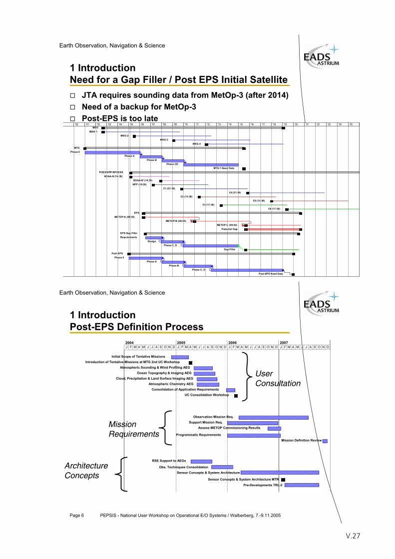
Page 5 PEPSIS - National User Workshop on Operational E/O Systems / Walberberg, 7.-9.11.2005
Earth Observation, Navigation & Science
1 IntroductionNeed for a Gap Filler / Post EPS Initial Satellite
JTA requires sounding data from MetOp-3 (after 2014)Need of a backup for MetOp-3Post-EPS is too late
MSGMSG-1
MSG-2MSG-3
MSG-4MTG
Phase 0Phase A
Phase BPhase CD
MTG-1 Need DatePOES/NPP/NPOESS
NOAA-N (14:30)NOAA-N' (14:30)NPP (10:30)
C1 (21:30)C4 (21:30)
C2 (13:30)C5 (13:30)
C3 (17:30)C6 (17:30)
EPSMETOP-A (09:30)
METOP-B (09:30)METOP-C (09:30)
Potential GapEPS Gap FillerRequirements
DesignPhase C, D
Gap FillerPost EPS
Phase 0Phase A
Phase BPhase C, D
Post-EPS Need Date
'00 '01 '02 '03 '04 '05 '06 '07 '08 '09 '10 '11 '12 '13 '14 '15 '16 '17 '18 '19 '20 '21 '22 '23 '24 '25
Page 6 PEPSIS - National User Workshop on Operational E/O Systems / Walberberg, 7.-9.11.2005
Earth Observation, Navigation & Science
1 IntroductionPost-EPS Definition Process
Initial Scope of Tentative MissionsIntroduction of Tentative Missions at MTG 2nd UC Workshop
Atmospheric Sounding & Wind Profiling AEGOcean Topography & Imaging AEG
Cloud, Precipitation & Land Surface Imaging AEGAtmospheric Chemistry AEG
Consolidation of Application RequirementsUC Consolidation Workshop
Observation Mission Req.Support Mission Req.
Assess METOP Commissioning Results
Programmatic RequirementsMission Definition Review
RSE Support to AEGs
Obs. Techniques ConsolidationSensor Concepts & System Architecture
Sensor Concepts & System Architecture MTR
Pre-Developments TRL-2
J F M A M J J A S O N D J F M A M J J A S O N D J F M A M J J A S O N D J F M A M J J A S O N D2004 2005 2006 2007
User Consultation
MissionRequirements
ArchitectureConcepts
V.27
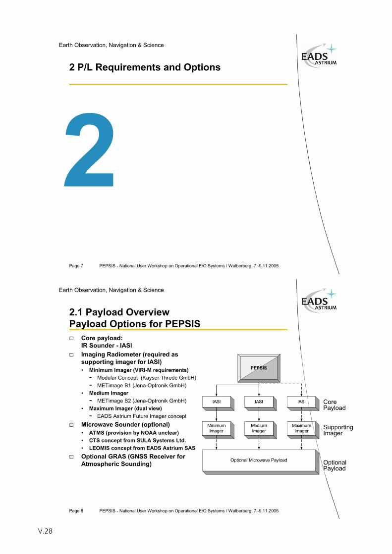
Page 7 PEPSIS - National User Workshop on Operational E/O Systems / Walberberg, 7.-9.11.2005
Earth Observation, Navigation & Science
2 P/L Requirements and Options
Page 8 PEPSIS - National User Workshop on Operational E/O Systems / Walberberg, 7.-9.11.2005
Earth Observation, Navigation & Science
IASI IASI IASI
MinimumImager
MediumImager
MaximumImager
PEPSIS
Optional Microwave Payload
2.1 Payload OverviewPayload Options for PEPSIS
Core payload:IR Sounder - IASIImaging Radiometer (required as supporting imager for IASI)• Minimum Imager (VIRI-M requirements)
- Modular Concept (Kayser Threde GmbH)- METimage B1 (Jena-Optronik GmbH)
• Medium Imager- METimage B2 (Jena-Optronik GmbH)
• Maximum Imager (dual view)- EADS Astrium Future Imager concept
Microwave Sounder (optional)• ATMS (provision by NOAA unclear)• CTS concept from SULA Systems Ltd.• LEOMIS concept from EADS Astrium SASOptional GRAS (GNSS Receiver for Atmospheric Sounding)
CorePayload
SupportingImager
OptionalPayload
V.28
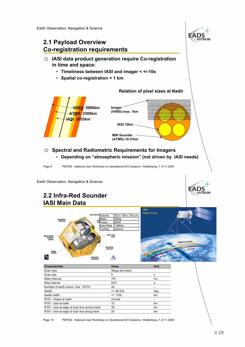
Page 9 PEPSIS - National User Workshop on Operational E/O Systems / Walberberg, 7.-9.11.2005
Earth Observation, Navigation & Science
Imager(VIIRS):max. 1km
IASI:12km
MW Sounder(ATMS):10-37km
IASI data product generation require Co-registration in time and space:
• Timeliness between IASI and imager < +/-10s• Spatial co-registration < 1 km
Spectral and Radiometric Requirements for Imagers• Depending on “atmospheric mission” (not driven by IASI needs)
Relation of pixel sizes at Nadir
2.1 Payload OverviewCo-registration requirements
VIIRS: 3000kmATMS: 2300km
IASI: 2052km
Page 10 PEPSIS - National User Workshop on Operational E/O Systems / Walberberg, 7.-9.11.2005
Earth Observation, Navigation & Science
2.2 Infra-Red Sounder IASI Main Data
Characteristic Value Unit Scan type Stepp and stare -Scan rate 8 sStare interval 151 msStep interval 8/37 sNumber of earth scans / line - EFOV 30 -Swath +/- 48.333 degSwath width +/- 1100 kmIFOV - shape at nadir circular -IFOV - size at nadir 12 kmIFOV - size at edge of scan line across track 39 kmIFOV - size at edge of scan line along track 20 km
Volume 120 x 108 x 134 cmMass 230kgPower 200WData Rate 1.5Mb/sCooling passive
V.29
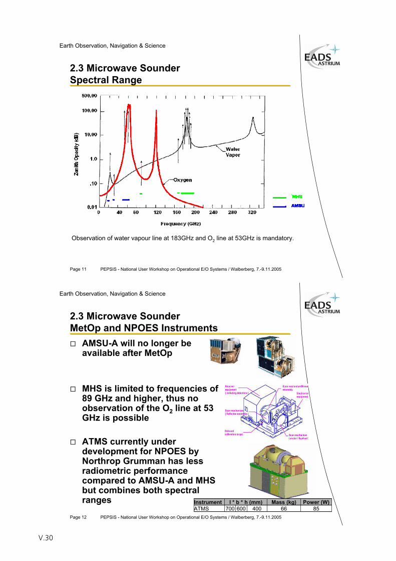
Page 11 PEPSIS - National User Workshop on Operational E/O Systems / Walberberg, 7.-9.11.2005
Earth Observation, Navigation & Science
2.3 Microwave Sounder Spectral Range
Observation of water vapour line at 183GHz and O2 line at 53GHz is mandatory.
Page 12 PEPSIS - National User Workshop on Operational E/O Systems / Walberberg, 7.-9.11.2005
Earth Observation, Navigation & Science
2.3 Microwave Sounder MetOp and NPOES Instruments
AMSU-A will no longer beavailable after MetOp
MHS is limited to frequencies of89 GHz and higher, thus no observation of the O2 line at 53 GHz is possible
ATMS currently under development for NPOES by Northrop Grumman has less radiometric performance compared to AMSU-A and MHS but combines both spectral ranges Instrument l * b * h (mm) Mass (kg) Power (W)
ATMS 700 600 400 66 85
V.30
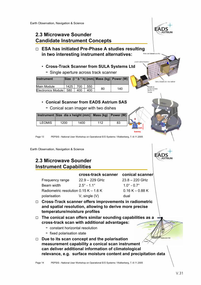
Page 13 PEPSIS - National User Workshop on Operational E/O Systems / Walberberg, 7.-9.11.2005
Earth Observation, Navigation & Science
2.3 Microwave Sounder Candidate Instrument Concepts
ESA has initiated Pre-Phase A studies resulting in two interesting instrument alternatives:
• Cross-Track Scanner from SULA Systems Ltd- Single aperture across track scanner
• Conical Scanner from EADS Astrium SAS- Conical scan imager with two dishes
Instrument Size (l * b * h) (mm) Mass (kg) Power (W)
Main Module 1425 700 550Electronics Module 580 400 400 80 140
8311214001200LEOMIS
Power (W)Mass (kg)Size dia x height (mm)Instrument
Earth
Scanning
Earth
Scanning
Page 14 PEPSIS - National User Workshop on Operational E/O Systems / Walberberg, 7.-9.11.2005
Earth Observation, Navigation & Science
2.3 Microwave SounderInstrument Capabilities
cross-track scanner conical scannerFrequency range 22.9 – 229 GHz 23.8 – 220 GHzBeam width 2.5° - 1.1° 1.0° - 0.7°Radiometric resolution 0.15 K – 1.6 K 0.16 K – 0.88 Kpolarisation V, single (V) dualCross-Track scanner offers improvements in radiometric and spatial resolution, allowing to derive more precise temperature/moisture profilesThe conical scan offers similar sounding capabilities as a cross-track scan with additional advantages:
- constant horizontal resolution- fixed polarisation state
Due to its scan concept and the polarisation measurement capability a conical scan instrument can deliver additional information of climatologicalrelevance, e.g. surface moisture content and precipitation data
V.31
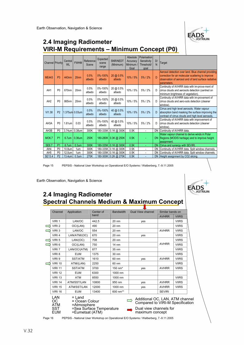
Page 15 PEPSIS - National User Workshop on Operational E/O Systems / Walberberg, 7.-9.11.2005
Earth Observation, Navigation & Science
2.4 Imaging RadiometerVIRI-M Requirements – Minimum Concept (P0)
Channel Priority CentralWL FWHM Reference
Scene
Expectedscenerange
SNR/NEDT(Minimum)
AbsoluteAccuracyMinimum /
Goal
PolarisationSensitivityThreshold/
goal
D/N Target
ME443 P3 443nm 20nm 0.5% albedo
0%-100% albedo
20 @ 0.5% albedo 10% / 5% 5% / 2% D
Aerosol detection over land. Blue channel providing correction for air molecular scattering to improve observation of aerosol and of land surface radiativeparameters.
AH1 P0 670nm 20nm 0.5% albedo
0%-100% albedo
20 @ 0.5% albedo 10% / 5% 5% / 2% D
Continuity of AVHRR data with im-prove-ment of cirrus clouds and aerosols detection (centred on minimum brightness of vegetation).
AH2 P0 865nm 20nm 0.5% albedo
0%-100% albedo
20 @ 0.5% albedo 10% / 5% 5% / 2% D
Continuity of AVHRR data with im-provement of cirrus clouds and aero-sols detection (cleaner window).
VI1.38 P2 1.375um 0.03um 0.5% albedo
0%-100% albedo
40 @ 0.5% albedo 10% / 5% 5% / 2% D
Cirrus and high level aerosols. Water vapour absorption band masking the surface improving the contrast of cirrus clouds and high level aerosols.
AH3A P0 1.61um 0.03 0.5% albedo
0%-100% albedo
40 @ 0.5% albedo 10% / 5% 5% / 2% D
Continuity of AVHRR data with improvement of cirrus clouds and aerosols detection (cleaner window).
AH3B P0 3.74um 0.38um 300K 180-335K 0.1K @ 300K 0.5K - DN Continuity of AVHRR data.
MO6.7 P1 6.7um 0.36um 250K 180-280K 0.3K @ 250K 0.5K - DNWater vapour channel to derive winds in Polar Regions (MODIS heritage) and to improve height assignment.
SE8.7 P1 8.7um 0.3um 300K 180-335K 0.1K @ 300K 0.5K - DN Cirrus and synergy with SEVIRI. AH4 P0 10.8um 1um 300K 180-335K 0.1K @ 300K 0.5K - DN Continuity of AVHRR data. Split window channels. AH5 P0 12.0um 1um 300K 180-335K 0.1K @ 300K 0.5K - DN Continuity of AVHRR data. Split window channels.
SE13.4 P2 13.4um 0.3um 270K 180-300K 0.2K @ 270K 0.5K - DN Height assignment by CO2 slicing.
Page 16 PEPSIS - National User Workshop on Operational E/O Systems / Walberberg, 7.-9.11.2005
Earth Observation, Navigation & Science
2.4 Imaging RadiometerSpectral Channels Medium & Maximum Concept
Similar bands on Channel Application Center of band
Bandwidth Dual View channel AVHRR VIIRS
VIRI 1 LAN/OC 442.5 20 nm yes VIIRS VIRI 2 OC/(LAN) 490 20 nm VIIRS VIRI 3 LAN/OC 554 20 nm VIIRS VIRI 4 LAN/ATM/(OC) 670 20 nm yes
AVHRR VIIRS
VIRI 5 LAN/(OC) 708 20 nm VIIRS VIRI 6 OC/(LAN) 750 14 nm VIIRS VIRI 7 LAN/OC/(ATM) 877 35 nm
AVHRR
VIIRS VIRI 8 EUM 1375 30 nm VIIRS VIRI 9 SST/ATM 1610 60 nm yes AVHRR VIIRS VIRI 10 ATM/(LAN) 2250 60 nm VIIRS VIRI 11 SST/ATM 3700 150 nm* yes AVHRR VIIRS VIRI 12 EUM 6300 1000 nm VIRI 13 ATM 8550 1000 nm VIIRS VIRI 14 ATM/SST/LAN 10800 950 nm yes AVHRR VIIRS VIRI 15 ATM/SST/LAN 12000 1000 nm yes AVHRR VIIRS VIRI 16 EUM 13400 600 nm** SEVIRI
LAN = LandOC = Ocean ColourATM =AtmosphereSST =Sea Surface TemperatureEUM =Eumetsat (ATM)
Additional OC, LAN, ATM channelCompared to VIRI-M SpecificationDual view channels for maximum concept
V.32
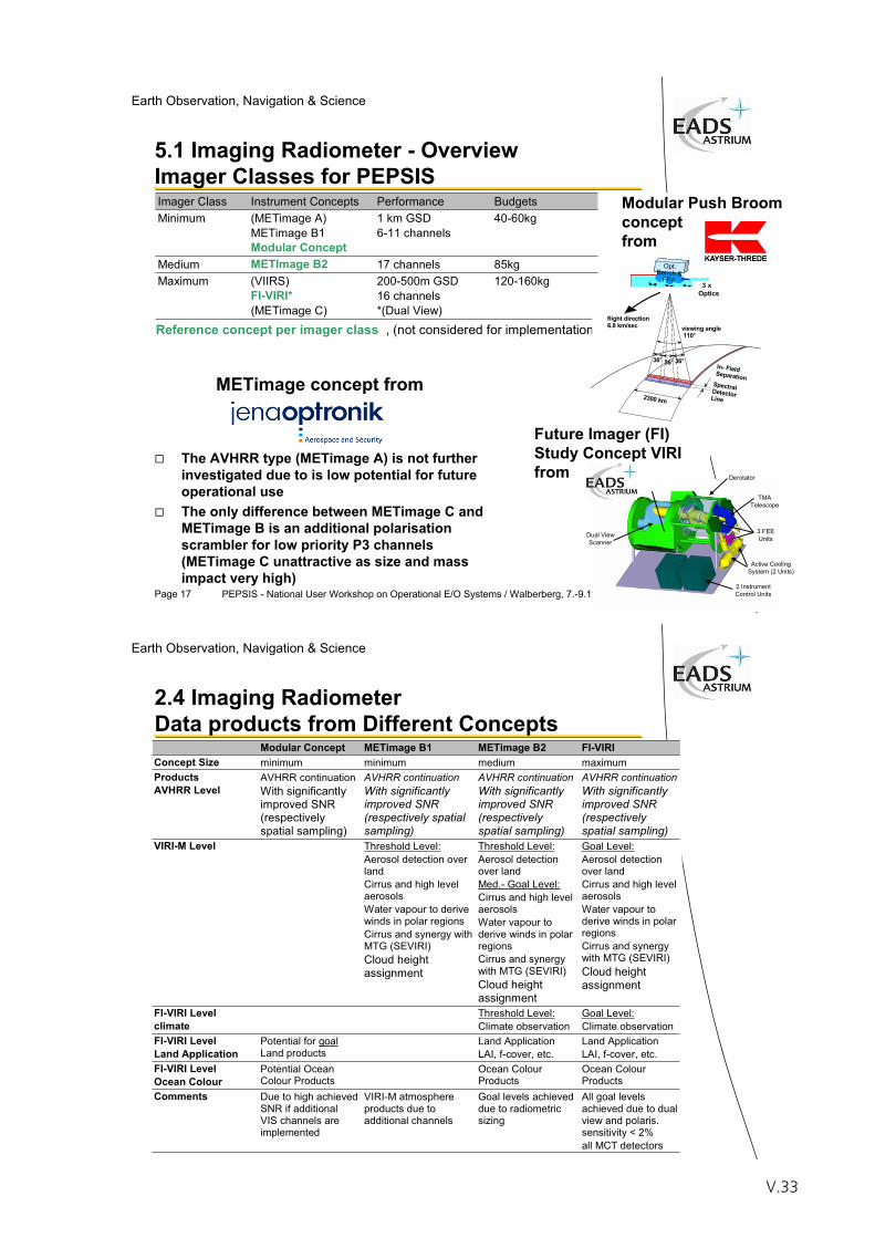
Page 17 PEPSIS - National User Workshop on Operational E/O Systems / Walberberg, 7.-9.11.2005
Earth Observation, Navigation & Science
Modular Push Broom conceptfrom
5.1 Imaging Radiometer - Overview Imager Classes for PEPSIS
METimage concept from
The AVHRR type (METimage A) is not further investigated due to is low potential for future operational useThe only difference between METimage C and METimage B is an additional polarisation scrambler for low priority P3 channels (METimage C unattractive as size and mass impact very high)
Imager Class Instrument Concepts Performance Budgets Minimum (METimage A)
METimage B1 Modular Concept
1 km GSD 6-11 channels
40-60kg
Medium METImage B2 17 channels 85kg Maximum (VIIRS)
FI-VIRI*(METimage C)
200-500m GSD 16 channels *(Dual View)
120-160kg
Reference concept per imager class , (not considered for implementation)
Derotator
TMATelescope
3 FEEUnits
Active CoolingSystem (2 Units)
Dual ViewScanner
TIR Black Bodies
2 InstrumentControl Units
Nadir
33°
33°
33°
FD
Opt.Bench &
FPA 3x1Optics
Nadir
33°
33°
33°
FD
Opt.Bench &
FPA 3x1Optics
In- FieldSeparationSpectralDetectorLine
36°
2300 km
flight direction6.8 km/sec viewing angle
110°
36° 36°
3 xOptics
Future Imager (FI) Study Concept VIRI from
Page 18 PEPSIS - National User Workshop on Operational E/O Systems / Walberberg, 7.-9.11.2005
Earth Observation, Navigation & Science
2.4 Imaging RadiometerData products from Different Concepts
Modular Concept METimage B1 METimage B2 FI-VIRIConcept Size minimum minimum medium maximum Products AVHRR Level
AVHRR continuation With significantly improved SNR (respectively spatial sampling)
AVHRR continuation With significantly improved SNR (respectively spatial sampling)
AVHRR continuation With significantly improved SNR (respectively spatial sampling)
AVHRR continuation With significantly improved SNR (respectively spatial sampling)
VIRI-M Level Threshold Level:Aerosol detection over land Cirrus and high level aerosols Water vapour to derive winds in polar regions Cirrus and synergy with MTG (SEVIRI) Cloud height assignment
Threshold Level:Aerosol detection over land Med.- Goal Level:Cirrus and high level aerosols Water vapour to derive winds in polar regions Cirrus and synergy with MTG (SEVIRI) Cloud height assignment
Goal Level:Aerosol detection over land Cirrus and high level aerosols Water vapour to derive winds in polar regions Cirrus and synergy with MTG (SEVIRI) Cloud height assignment
FI-VIRI Level climate
Threshold Level:Climate observation
Goal Level:Climate observation
FI-VIRI Level Land Application
Potential for goal Land products
Land Application LAI, f-cover, etc.
Land Application LAI, f-cover, etc.
FI-VIRI Level Ocean Colour
Potential Ocean Colour Products
Ocean Colour Products
Ocean Colour Products
Comments Due to high achieved SNR if additional VIS channels are implemented
VIRI-M atmosphere products due to additional channels
Goal levels achieved due to radiometric sizing
All goal levels achieved due to dual view and polaris. sensitivity < 2% all MCT detectors
V.33
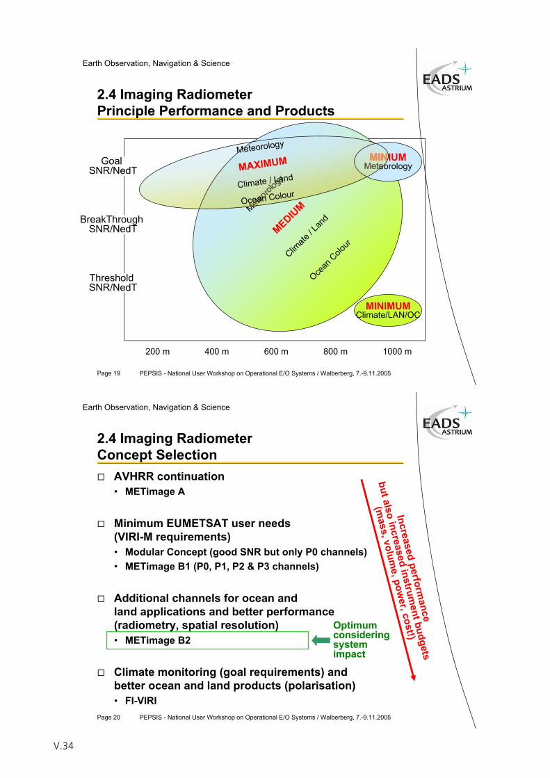
Page 19 PEPSIS - National User Workshop on Operational E/O Systems / Walberberg, 7.-9.11.2005
Earth Observation, Navigation & Science
2.4 Imaging RadiometerPrinciple Performance and Products
200 m 400 m 600 m 800 m 1000 m
BreakThroughSNR/NedT
GoalSNR/NedT
ThresholdSNR/NedT
MINIMUMClimate/LAN/OC
Meteoro
logy
MEDIUM
Climate
/ Lan
d
Ocean
Colour
MINIUMMeteorology
Meteorology
MAXIMUM
Climate / Land
Ocean Colour
Page 20 PEPSIS - National User Workshop on Operational E/O Systems / Walberberg, 7.-9.11.2005
Earth Observation, Navigation & Science
2.4 Imaging RadiometerConcept Selection
AVHRR continuation• METimage A
Minimum EUMETSAT user needs (VIRI-M requirements)• Modular Concept (good SNR but only P0 channels)• METimage B1 (P0, P1, P2 & P3 channels)
Additional channels for ocean andland applications and better performance (radiometry, spatial resolution)• METimage B2
Climate monitoring (goal requirements) and better ocean and land products (polarisation) • FI-VIRI
Optimumconsideringsystemimpact
Increasedperform
ance
but alsoincreased
instrument budgets
(mass, volum
e, power, cost!)
V.34
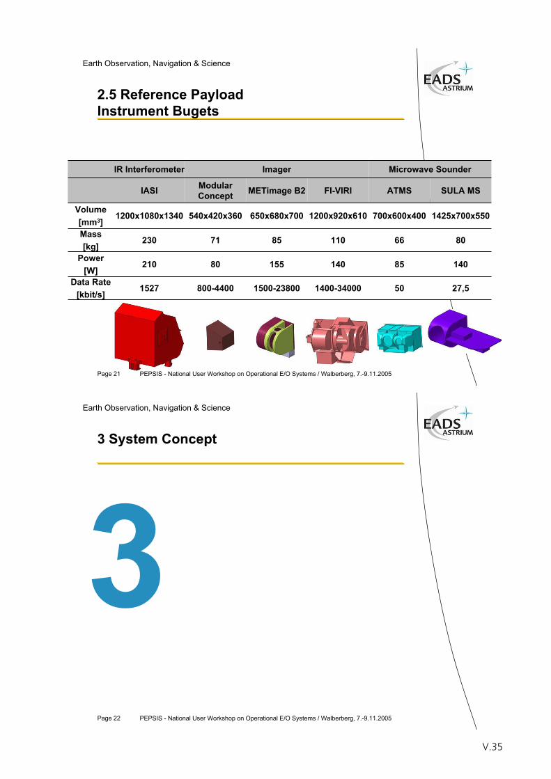
Page 21 PEPSIS - National User Workshop on Operational E/O Systems / Walberberg, 7.-9.11.2005
Earth Observation, Navigation & Science
2.5 Reference PayloadInstrument Bugets
IR Interferometer Imager Microwave Sounder
IASI ModularConcept
540x420x360
71
80
800-4400
METimage B2 FI-VIRI SULA MS
Volume[mm3]
1200x1080x1340
ATMS
650x680x700
85
155
Mass[kg]
230
1425x700x550
1500-23800
700x600x4001200x920x610
80110
140
66
85
1400-34000
140
50 27,5
Power[W]
210
Data Rate[kbit/s]
1527
Page 22 PEPSIS - National User Workshop on Operational E/O Systems / Walberberg, 7.-9.11.2005
Earth Observation, Navigation & Science
3 System Concept
V.35
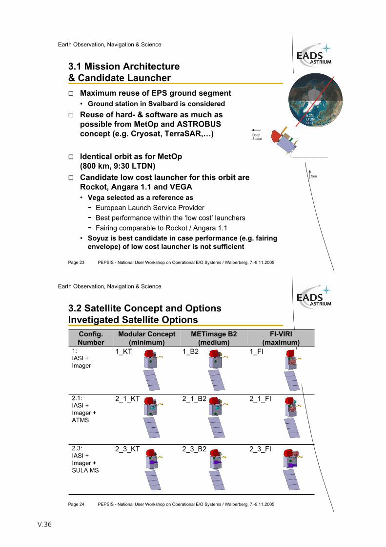
Page 23 PEPSIS - National User Workshop on Operational E/O Systems / Walberberg, 7.-9.11.2005
Earth Observation, Navigation & Science
3.1 Mission Architecture & Candidate Launcher
Maximum reuse of EPS ground segment• Ground station in Svalbard is consideredReuse of hard- & software as much as possible from MetOp and ASTROBUS concept (e.g. Cryosat, TerraSAR,…)
Identical orbit as for MetOp(800 km, 9:30 LTDN)Candidate low cost launcher for this orbit are Rockot, Angara 1.1 and VEGA• Vega selected as a reference as
- European Launch Service Provider- Best performance within the ‘low cost’ launchers- Fairing comparable to Rockot / Angara 1.1
• Soyuz is best candidate in case performance (e.g. fairing envelope) of low cost launcher is not sufficient
Sun
9,30hLTDNSSO
DeepSpace
Page 24 PEPSIS - National User Workshop on Operational E/O Systems / Walberberg, 7.-9.11.2005
Earth Observation, Navigation & Science
3.2 Satellite Concept and OptionsInvetigated Satellite Options
Config.Number
Modular Concept(minimum)
METimage B2(medium)
FI-VIRI(maximum)
1:IASI +Imager
1_KT 1_B2
2_1_B2
2_3_B2
1_FI
2.1:IASI +Imager +ATMS
2_1_KT 2_1_FI
2.3:IASI +Imager +SULA MS
2_3_KT 2_3_FI
V.36
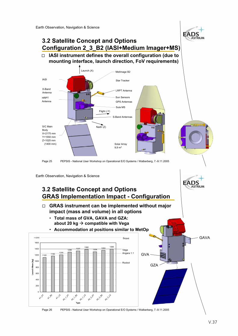
Page 25 PEPSIS - National User Workshop on Operational E/O Systems / Walberberg, 7.-9.11.2005
Earth Observation, Navigation & Science
3.2 Satellite Concept and Options Configuration 2_3_B2 (IASI+Medium Imager+MS)
Launch (X)
IASI
S/C MainBodyX=2175 mmY=1550 mmZ=1025 mm (1400 mm)
X-BandAntenna
HRPTAntenna
MetImage B2
Nadir (Z)
Flight (-Y)
LRPT Antenna
GPS Antennas
S-Band Antennas
Solar Array9,9 m2
Star Tracker
Sun Sensors
Sula MS
IASI instrument defines the overall configuration (due to mounting interface, launch direction, FoV requirements)
Page 26 PEPSIS - National User Workshop on Operational E/O Systems / Walberberg, 7.-9.11.2005
Earth Observation, Navigation & Science
3.2 Satellite Concept and Options GRAS Implementation Impact - Configuration
GRAS instrument can be implemented without major impact (mass and volume) in all options• Total mass of GVA, GAVA and GZA:
about 20 kg compatible with Vega• Accommodation at positions similar to MetOp
GZA
GAVA
GVA11221165 1205
12961337
13821309
13531395
0
200
400
600
800
1000
1200
1400
1600
A1_KT
A1_B2
A1_LS
A2_1_
KT
A2_1_
B2
A2_1_
LS
A2_3_
KT
A2_3_
B2
A2_3_
LS
Type
Lau
nch
Mas
s [k
g]
VegaAngara 1.1
Rockot
Soyuz>>2000
V.37
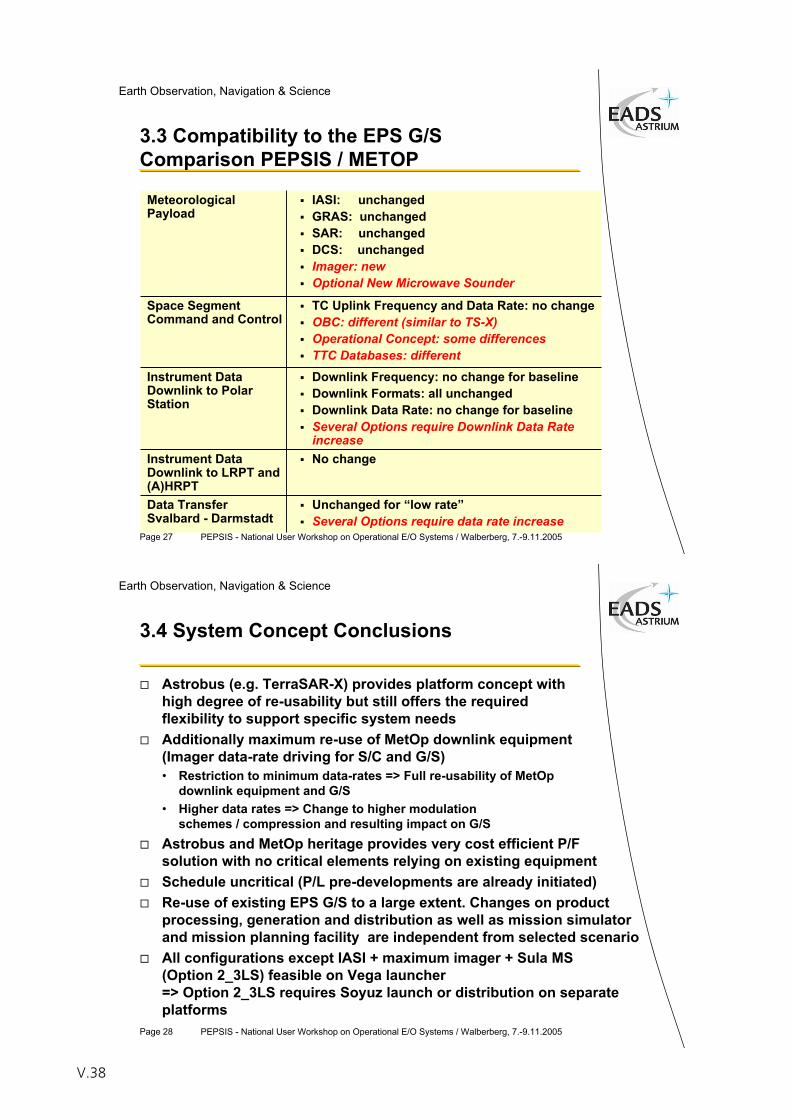
Page 27 PEPSIS - National User Workshop on Operational E/O Systems / Walberberg, 7.-9.11.2005
Earth Observation, Navigation & Science
3.3 Compatibility to the EPS G/SComparison PEPSIS / METOP
MeteorologicalPayload
IASI: unchangedGRAS: unchangedSAR: unchangedDCS: unchangedImager: newOptional New Microwave Sounder
Space Segment Command and Control
TC Uplink Frequency and Data Rate: no changeOBC: different (similar to TS-X)Operational Concept: some differencesTTC Databases: different
Instrument Data Downlink to Polar Station
Downlink Frequency: no change for baselineDownlink Formats: all unchangedDownlink Data Rate: no change for baselineSeveral Options require Downlink Data Rate increase
Instrument Data Downlink to LRPT and (A)HRPT
No change
Data TransferSvalbard - Darmstadt
Unchanged for “low rate”Several Options require data rate increase
Page 28 PEPSIS - National User Workshop on Operational E/O Systems / Walberberg, 7.-9.11.2005
Earth Observation, Navigation & Science
3.4 System Concept Conclusions
Astrobus (e.g. TerraSAR-X) provides platform concept with high degree of re-usability but still offers the required flexibility to support specific system needsAdditionally maximum re-use of MetOp downlink equipment (Imager data-rate driving for S/C and G/S)• Restriction to minimum data-rates => Full re-usability of MetOp
downlink equipment and G/S• Higher data rates => Change to higher modulation
schemes / compression and resulting impact on G/SAstrobus and MetOp heritage provides very cost efficient P/Fsolution with no critical elements relying on existing equipmentSchedule uncritical (P/L pre-developments are already initiated)Re-use of existing EPS G/S to a large extent. Changes on product processing, generation and distribution as well as mission simulator and mission planning facility are independent from selected scenarioAll configurations except IASI + maximum imager + Sula MS (Option 2_3LS) feasible on Vega launcher=> Option 2_3LS requires Soyuz launch or distribution on separate platforms
V.38
Page 29 PEPSIS - National User Workshop on Operational E/O Systems / Walberberg, 7.-9.11.2005
Earth Observation, Navigation & Science
4 Recommendation & Implementation Scenario
Page 30 PEPSIS - National User Workshop on Operational E/O Systems / Walberberg, 7.-9.11.2005
Earth Observation, Navigation & Science
4 Recommendation & Implementation Scenario Candidate Payload
Apart from IASI no existing European instruments are suitable for PEPSISImager:• VIIRS (US) existing but price and availability not clear• no large cost difference between minimum and medium concept• medium concept proposed as a baseline for PEPSISMicrowave Sounder• ATMS offers reduced performance and is not European• ATMS-like MS found to be no design driver – implementation
uncritical• Sula -CTS feasible option but leads to a more complex structure
design (structure cost no major contributor to overall cost)• LEOMIS concept not compatible with IASI onboard a low-cost
platform – dedicated Sounder platform recommended• Sula MS proposed as a baseline for PEPSISImplementation of GRAS uncritical for all options (no design driver)
V.39
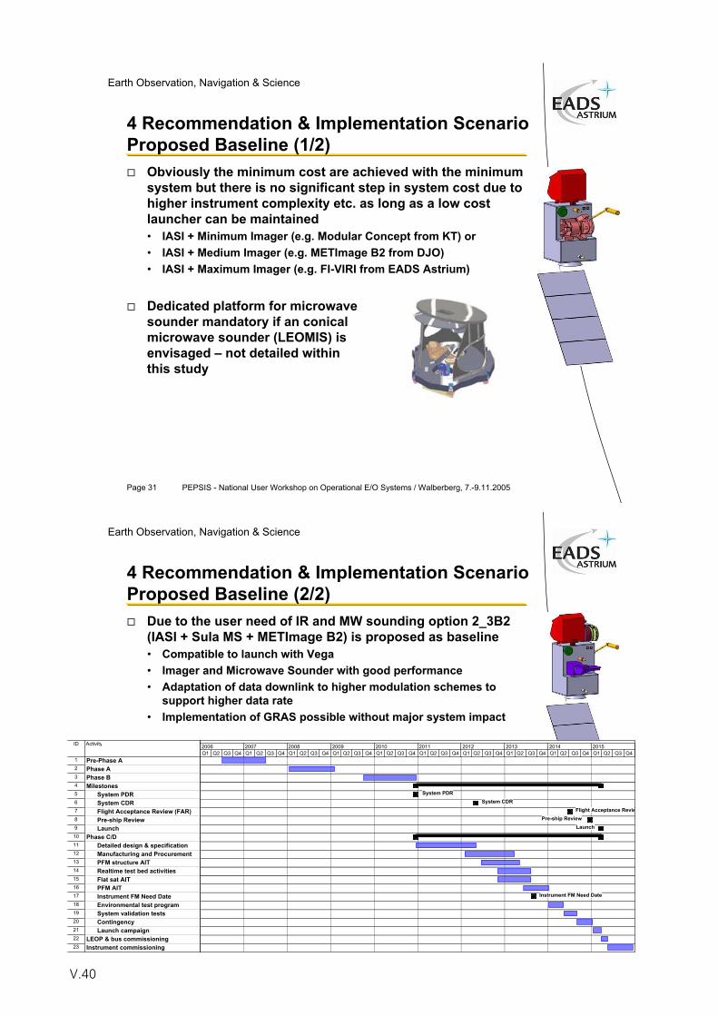
Page 31 PEPSIS - National User Workshop on Operational E/O Systems / Walberberg, 7.-9.11.2005
Earth Observation, Navigation & Science
4 Recommendation & Implementation Scenario Proposed Baseline (1/2)
Obviously the minimum cost are achieved with the minimum system but there is no significant step in system cost due to higher instrument complexity etc. as long as a low cost launcher can be maintained• IASI + Minimum Imager (e.g. Modular Concept from KT) or• IASI + Medium Imager (e.g. METImage B2 from DJO)• IASI + Maximum Imager (e.g. FI-VIRI from EADS Astrium)
Dedicated platform for microwave sounder mandatory if an conical microwave sounder (LEOMIS) is envisaged – not detailed within this study
Page 32 PEPSIS - National User Workshop on Operational E/O Systems / Walberberg, 7.-9.11.2005
Earth Observation, Navigation & Science
4 Recommendation & Implementation Scenario Proposed Baseline (2/2)
Due to the user need of IR and MW sounding option 2_3B2 (IASI + Sula MS + METImage B2) is proposed as baseline• Compatible to launch with Vega• Imager and Microwave Sounder with good performance• Adaptation of data downlink to higher modulation schemes to
support higher data rate• Implementation of GRAS possible without major system impact
ID Activity
1 Pre-Phase A2 Phase A3 Phase B 4 Milestones5 System PDR6 System CDR7 Flight Acceptance Review (FAR)8 Pre-ship Review9 Launch10 Phase C/D11 Detailed design & specification12 Manufacturing and Procurement13 PFM structure AIT 14 Realtime test bed activities15 Flat sat AIT16 PFM AIT17 Instrument FM Need Date18 Environmental test program19 System validation tests20 Contingency21 Launch campaign22 LEOP & bus commissioning23 Instrument commissioning
System PDRSystem CDR
Flight Acceptance ReviePre-ship Review
Launch
Instrument FM Need Date
Q1 Q2 Q3 Q4 Q1 Q2 Q3 Q4 Q1 Q2 Q3 Q4 Q1 Q2 Q3 Q4 Q1 Q2 Q3 Q4 Q1 Q2 Q3 Q4 Q1 Q2 Q3 Q4 Q1 Q2 Q3 Q4 Q1 Q2 Q3 Q4 Q1 Q2 Q3 Q42006 2007 2008 2009 2010 2011 2012 2013 2014 2015
V.40
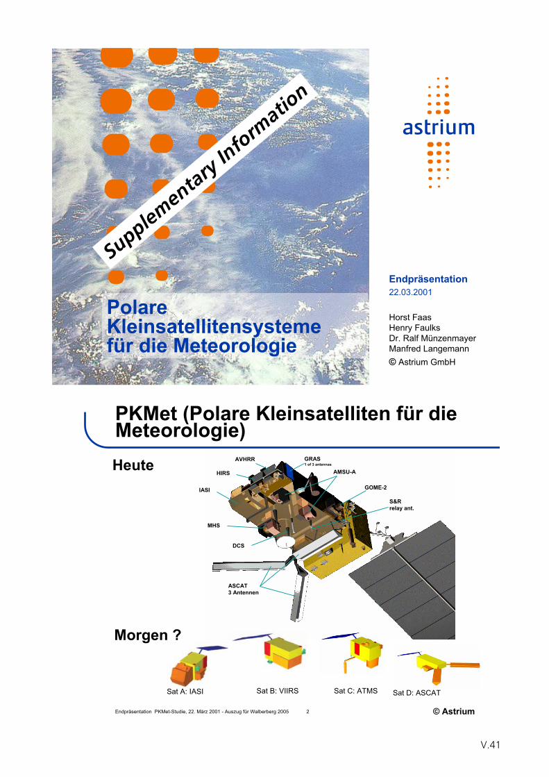
PolareKleinsatellitensystemefür die Meteorologie
Endpräsentation22.03.2001
Horst FaasHenry FaulksDr. Ralf MünzenmayerManfred Langemann© Astrium GmbH
Supplem
entaryInforma
tion
Endpräsentation PKMet-Studie, 22. März 2001 - Auszug für Walberberg 2005 2 © Astrium
IASI
AVHRR
HIRS
GRAS1 of 3 antennas
AMSU-A
GOME-2
S&Rrelay ant.
ASCAT3 Antennen
DCS
MHS
PKMet (Polare Kleinsatelliten für die Meteorologie)Heute
Morgen ?
Sat A: IASI Sat B: VIIRS Sat C: ATMS Sat D: ASCAT
V.41
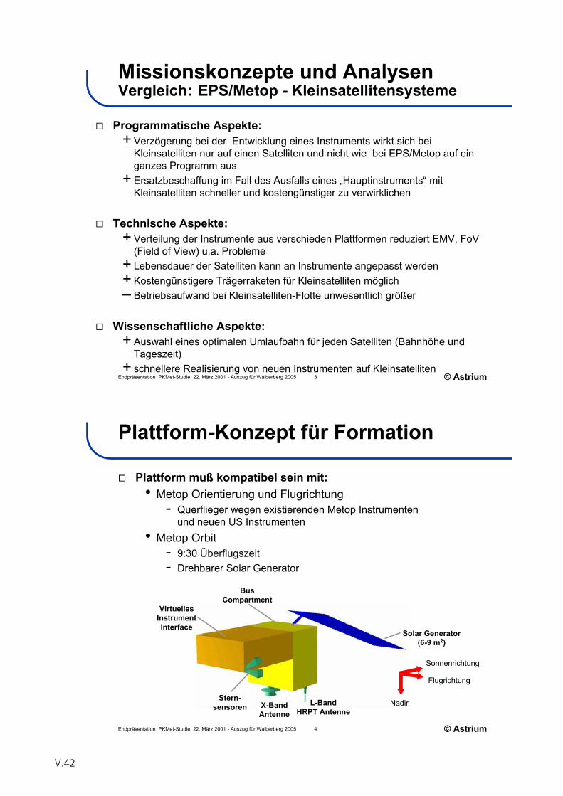
Endpräsentation PKMet-Studie, 22. März 2001 - Auszug für Walberberg 2005 3 © Astrium
Missionskonzepte und AnalysenVergleich: EPS/Metop - Kleinsatellitensysteme
Programmatische Aspekte:+ Verzögerung bei der Entwicklung eines Instruments wirkt sich bei
Kleinsatelliten nur auf einen Satelliten und nicht wie bei EPS/Metop auf ein ganzes Programm aus
+ Ersatzbeschaffung im Fall des Ausfalls eines „Hauptinstruments“ mit Kleinsatelliten schneller und kostengünstiger zu verwirklichen
Technische Aspekte:+ Verteilung der Instrumente aus verschieden Plattformen reduziert EMV, FoV
(Field of View) u.a. Probleme+ Lebensdauer der Satelliten kann an Instrumente angepasst werden+ Kostengünstigere Trägerraketen für Kleinsatelliten möglich– Betriebsaufwand bei Kleinsatelliten-Flotte unwesentlich größer
Wissenschaftliche Aspekte:+ Auswahl eines optimalen Umlaufbahn für jeden Satelliten (Bahnhöhe und
Tageszeit)+ schnellere Realisierung von neuen Instrumenten auf Kleinsatelliten
Endpräsentation PKMet-Studie, 22. März 2001 - Auszug für Walberberg 2005 4 © Astrium
Plattform-Konzept für Formation
Plattform muß kompatibel sein mit:• Metop Orientierung und Flugrichtung
- Querflieger wegen existierenden Metop Instrumentenund neuen US Instrumenten
• Metop Orbit- 9:30 Überflugszeit- Drehbarer Solar Generator
Solar Generator(6-9 m2)
Sonnenrichtung
Flugrichtung
NadirX-BandAntenne
L-BandHRPT Antenne
Stern-sensoren
BusCompartment
VirtuellesInstrumentInterface
V.42
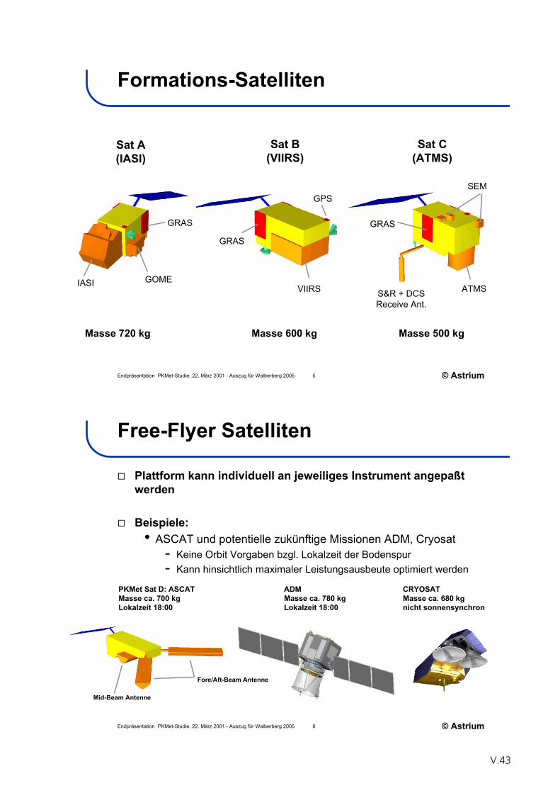
Endpräsentation PKMet-Studie, 22. März 2001 - Auszug für Walberberg 2005 5 © Astrium
Formations-Satelliten
VIIRS
GRAS
ATMS
GRAS
SEM
IASI GOME
GRAS
S&R + DCSReceive Ant.
GPS
Sat A(IASI)
Sat B(VIIRS)
Sat C(ATMS)
Masse 720 kg Masse 600 kg Masse 500 kg
Endpräsentation PKMet-Studie, 22. März 2001 - Auszug für Walberberg 2005 6 © Astrium
Free-Flyer Satelliten
Plattform kann individuell an jeweiliges Instrument angepaßt werden
Beispiele:• ASCAT und potentielle zukünftige Missionen ADM, Cryosat
- Keine Orbit Vorgaben bzgl. Lokalzeit der Bodenspur- Kann hinsichtlich maximaler Leistungsausbeute optimiert werden
PKMet Sat D: ASCATMasse ca. 700 kgLokalzeit 18:00
ADMMasse ca. 780 kgLokalzeit 18:00
CRYOSATMasse ca. 680 kgnicht sonnensynchron
Mid-Beam Antenne
Fore/Aft-Beam Antenne
V.43
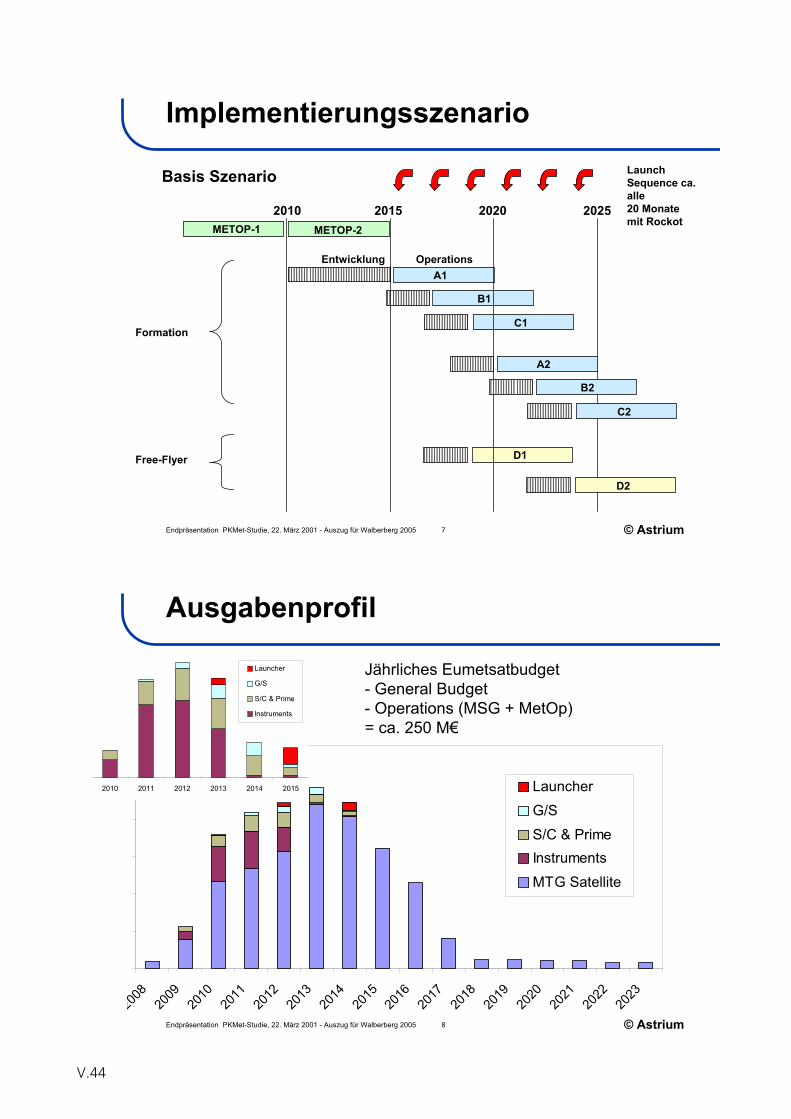
Endpräsentation PKMet-Studie, 22. März 2001 - Auszug für Walberberg 2005 7 © Astrium
Implementierungsszenario
Basis Szenario
2010 2015 2020 2025
Formation
A1
B1
C1
D1
LaunchSequence ca. alle20 Monate mit Rockot
METOP-2METOP-1
A2
B2
C2
D2
Free-Flyer
OperationsEntwicklung
Endpräsentation PKMet-Studie, 22. März 2001 - Auszug für Walberberg 2005 8 © Astrium
Ausgabenprofil
2008
2009
2010
2011
2012
2013
2014
2015
2016
2017
2018
2019
2020
2021
2022
2023
Launcher
G/S
S/C & PrimeInstruments
MTG Satellite
2010 2011 2012 2013 2014 2015
Launcher
G/S
S/C & Prime
Instruments
Jährliches Eumetsatbudget- General Budget- Operations (MSG + MetOp)= ca. 250 M€
V.44
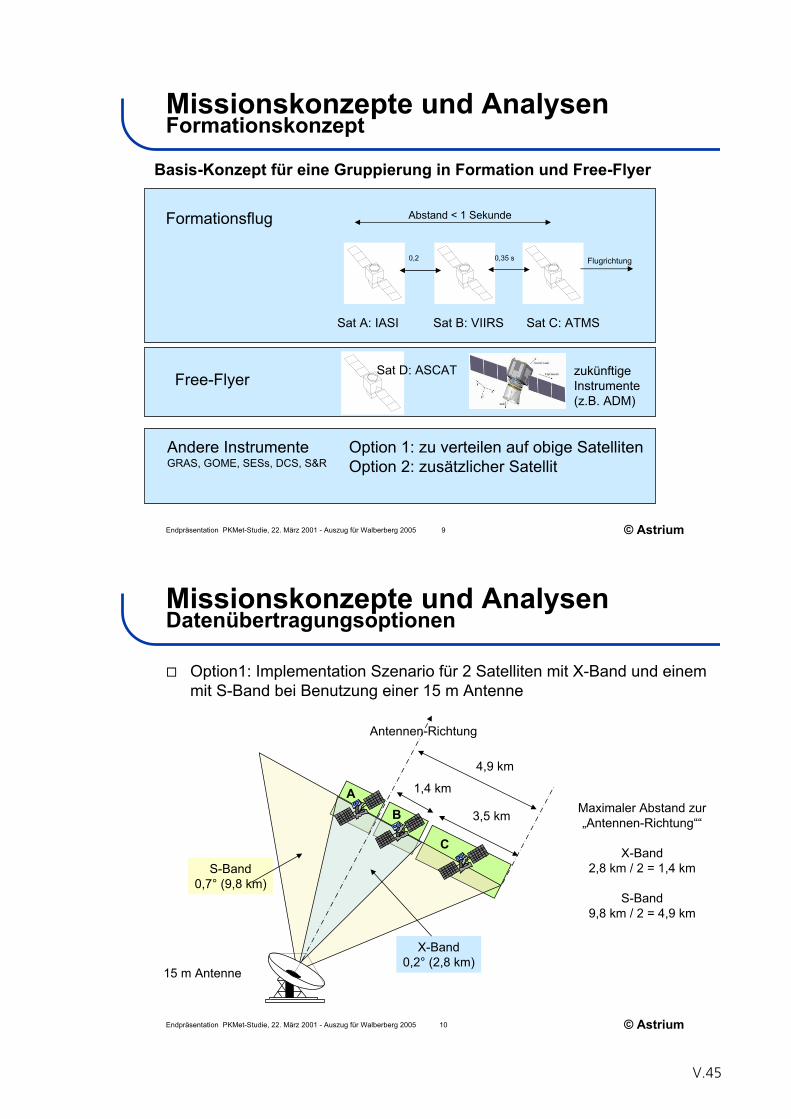
Endpräsentation PKMet-Studie, 22. März 2001 - Auszug für Walberberg 2005 9 © Astrium
Missionskonzepte und AnalysenFormationskonzept
Sat A: IASI Sat B: VIIRS Sat C: ATMS
Abstand < 1 Sekunde
0,2 0,35 s
Formationsflug
Free-Flyer Sat D: ASCAT
Andere InstrumenteGRAS, GOME, SESs, DCS, S&R
zukünftigeInstrumente(z.B. ADM)
Option 1: zu verteilen auf obige SatellitenOption 2: zusätzlicher Satellit
Basis-Konzept für eine Gruppierung in Formation und Free-Flyer
Flugrichtung
Endpräsentation PKMet-Studie, 22. März 2001 - Auszug für Walberberg 2005 10 © Astrium
Missionskonzepte und AnalysenDatenübertragungsoptionen
Option1: Implementation Szenario für 2 Satelliten mit X-Band und einem mit S-Band bei Benutzung einer 15 m Antenne
15 m Antenne
X-Band0,2° (2,8 km)
3,5 km
S-Band0,7° (9,8 km)
Maximaler Abstand zur „Antennen-Richtung““
X-Band2,8 km / 2 = 1,4 km
S-Band9,8 km / 2 = 4,9 km
4,9 km
1,4 km
Antennen-Richtung
AB
C
V.45
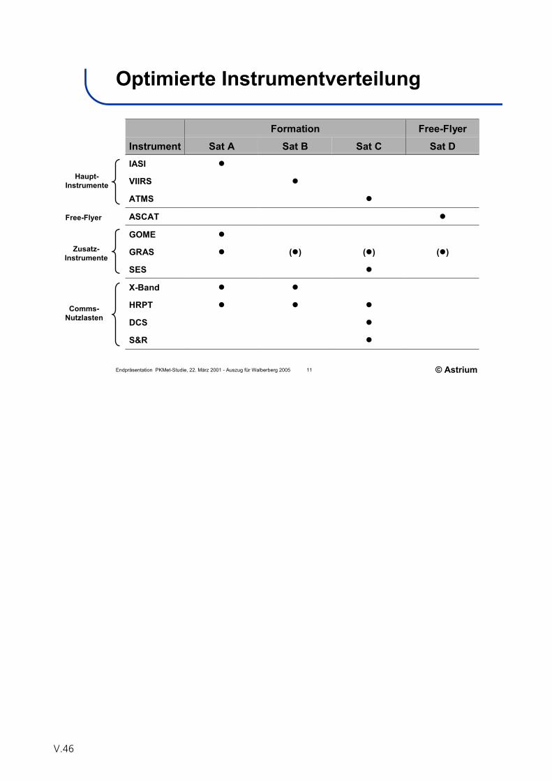
Endpräsentation PKMet-Studie, 22. März 2001 - Auszug für Walberberg 2005 11 © Astrium
Optimierte Instrumentverteilung
Formation Free-Flyer
Instrument Sat A Sat B Sat C Sat DIASI
VIIRS
ATMS
ASCAT
GOME
GRAS ( ) ( ) ( )
SES
X-Band
HRPT
DCS
S&R
Haupt-Instrumente
Free-Flyer
Zusatz-Instrumente
Comms-Nutzlasten
V.46

Chapter VI
Results of the Working Groups

Working Group
Severe Weather Forecasting and Nowcasting
Participants:
G. Steinhorst, DWD (Chair)
W. Benesch, DWD
K. Berndt, DJO
Th. Böhm, DWD
U. Gärtner, GEO
S.Hofer, Kayser-Threde
N. Jakowski, DLR
H. Nothaft, AIM
O. Roll, DWD
O. Sievers, DWD
R. Ullrich, DWD
R. Stuhlmann, EUMETSAT
P. Ingmann, ESA
VI.1

VI.2
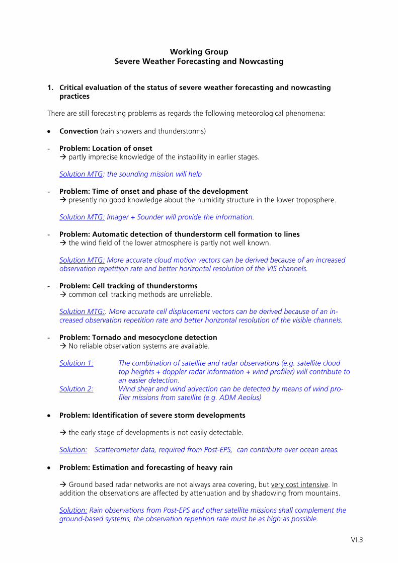
Working Group Severe Weather Forecasting and Nowcasting
1. Critical evaluation of the status of severe weather forecasting and nowcasting
practices There are still forecasting problems as regards the following meteorological phenomena:
• Convection (rain showers and thunderstorms) - Problem: Location of onset
partly imprecise knowledge of the instability in earlier stages.
Solution MTG: the sounding mission will help
- Problem: Time of onset and phase of the development presently no good knowledge about the humidity structure in the lower troposphere.
Solution MTG: Imager + Sounder will provide the information.
- Problem: Automatic detection of thunderstorm cell formation to lines
the wind field of the lower atmosphere is partly not well known. Solution MTG: More accurate cloud motion vectors can be derived because of an increased observation repetition rate and better horizontal resolution of the VIS channels.
- Problem: Cell tracking of thunderstorms common cell tracking methods are unreliable.
Solution MTG:. More accurate cell displacement vectors can be derived because of an in-creased observation repetition rate and better horizontal resolution of the visible channels.
- Problem: Tornado and mesocyclone detection No reliable observation systems are available.
Solution 1: The combination of satellite and radar observations (e.g. satellite cloud
top heights + doppler radar information + wind profiler) will contribute to an easier detection.
Solution 2: Wind shear and wind advection can be detected by means of wind pro-filer missions from satellite (e.g. ADM Aeolus)
• Problem: Identification of severe storm developments
the early stage of developments is not easily detectable.
Solution: Scatterometer data, required from Post-EPS, can contribute over ocean areas. • Problem: Estimation and forecasting of heavy rain
Ground based radar networks are not always area covering, but very cost intensive. In
addition the observations are affected by attenuation and by shadowing from mountains. Solution: Rain observations from Post-EPS and other satellite missions shall complement the ground-based systems, the observation repetition rate must be as high as possible.
VI.3
• Problem field: Visibility, fog (cloud base), cloud layer, aerosol information especially
for aviation and other transport systems
No area covered information is available.
Solution: Satellite-based LIDAR / cloud radar missions shall provide those information in the future.
• Problem: Turbulence in the atmosphere
Turbulence is not measured although the information is very important for aviation.
Solution: The working group could not find an answer to this problem field.. A partial solu-tion could be the observation of the tropopause by LIDAR-measurements.
2. Innovative observation methods and services for the improvement of nowcasting • Targeted Observations - Targeted observations are important for quasi-continuous monitoring of specific, especially
severe weather events.
Solution MTG: Two solutions can be imagined: a) relevant areas shall be observed by means of higher temporal and horizontal resolution; b) or a dedicated area band (e.g. the first third of the instrument scan to observe Europe) could be scanned with a higher temporal and horizontal resolution than the residual scan
• Lightning Imager
Lightning imagers on board of satellites provide in contrast to ground-based systems infor-mation on flashs from cloud to cloud, inside clouds and from cloud to ground.
Following aspects plead for a lightning imager mission: - An additional advance warning time of up to 10 min. is achievable by early detection of
lightning in clouds (discharges in clouds precede the lightning between cloud and ground). Therewith an early assessment of further development of severe convection is facilitated and early indications on a possible development of tornadoes can be derived.
- Aviation safety (risks from flash strikes) is improved. - Improved detection of lightning in comparison to the ground-based systems is provided. - Data is input for statistical weather forecasting methods (e.g. MOS). - Observations may contribute to climate monitoring (registration of changes in occur-
rence, frequency , and intensity of thunderstorms as a result of global warming). - Data may contribute to atmospheric chemistry applications (source for NOx). - In the long run a lightning mission might be probably more cost efficient in comparison
to area covered ground-based lightning detection systems, especially over oceans. The lightning imager on MTG is regarded as essential for nowcasting and severe weather warnings purposes.
Note: USA / NOAA will operate a lightning imager on the next generation of GOES satellites (GOES-R).
VI.4
3. A new forecasting task: Space Weather • Definition of Space Weather
Space Weather includes the conditions and processes of the sun, in the magnetosphere, thermosphere and ionosphere which may endanger technical systems in space and on earth as well as life.
• Importance of Space Weather
- Impact on the dispersion of electromagnetic signals in communication and navigation systems
- Risk of damage of satellites - Exposure on aircrews and passengers - Impact of atmospherics on radar systems (L-band) - Probable impact on cloud state parameters and climate
Due to the importance of space weather monitoring, operational forecasts including warnings are required. Note: No new technological developments are required for services in the field of Space Weather, in fact an extended use of GRAS and SEM on METOP is sufficient - but no ope- rational service with committed obligations is available so far in Germany. 4. Assessment of the MTG concepts • Imager: The user requirements for the temporal and spatial resolution as findings of the
pre-phase-A study and of the EUMETSAT expert groups are in agreement with the view of the working group:
horizontal resolution: ≤ 500 m SSP (e.g. for monitoring of fog, convection) corresponding to ≤ 1 km for Central Europe temporal resolution: ≤ 3 minutes (e.g. for monitoring of the development of con-
vection) • An Imager, possibly in combination with a Sounder, is required for monitoring the at-
mospheric instability • Sounder and Imager shall be on one platform either. • A lightning imager is essential, but can be simpler than a 4-camera-system.
VI.5
5. Assessment of the presented Post-EPS concepts • An Imager is required for:
- detection of forest fires - detection of snow in valleys (esp. in the Alps) - monitoring of sea ice for ship routing
- Relevance of an imager for nowcasting (0-2 hours forecast period):
During the MTG-era the relevance of the polar orbiting satellites for nowcasting pur-poses is less demanding, because the performance of the MTG-imager will be better compared to MSG. It has to be clarified if there are specific requirements of the armed forces and the crisis management as regards the performance of an imager in the post-EPS era for meteoro-logical purposes.
• Relevance of Post-EPS data for very-short-range forecasting (2-12 hours forecast
period) A greater demand for data from polar orbiting satellites is seen for the task of very-short-range forecasting, which will be increasingly based on numerical weather models. Regional models in the post-EPS era are expected to provide suitable forecasts already for forecast time periods beginning with one hour. The number of overpasses per day is essential for the effective use of data from polar orbiting satellites in regional models. The requirements for very-short-range forecasts correspond to the requirements for regional NWP models.
VI.6
Working Group
Numerical Weather Prediction
Participants:
N. Bormann, ECMWF (Chair),
Ch. Köpken, DWD
M. Alpers, DLR Bonn
J. Fischer, FU Berlin
H. Lübberstedt, OHB System
B. Ritter, DWD
G. Seuffert, BMVBW
U. Schumann, DLR IPA
F. Tanner, EADS Astrium
B. Voß, Jena-Optronik
J. Wickert, GFZ Potsdam
Additional Input:
P. Bauer, ECMWF
G, Heygster, Uni. Bremen
VI.7

VI.8
Working Group Numerical Weather Prediction
NWP framework in 2015/2025 Based on past trends, operational Numerical Weather Prediction (NWP) for the MTG/Post-EPS time-frame is expected to evolve as follows, driven by requirements of NWP users (see also MTG Position Papers “Requirements of Observation for Regional/Global NWP”, 20021):
• Improved NWP products for current applications (incl. forecasts of main weather parameters; specialized aviation forecasts; severe weather forecasts; monthly and seasonal forecasts)
• Extended applications expected: incl. monitoring of atmospheric constituents (global and regional), air quality forecasts, lightning forecasts (for regional NWP)
• Increased horizontal and vertical resolution of NWP models: Horizontal resolution: Global models: 8-15 km (2015), 3-5 km (2025) Regional models: about 1km (2015); 0.2-0.3km (2025) Vertical resolution: Global models: Boundary layer: 70 m (2015), 40 m (2025) Free atmosphere: 300 m (2015), 200 m (2025) Stratosphere: 500 m (2015), 200 m (2025) Regional models: 100 levels (2015), 200 levels (2025) Model top for global models: about 0.01 hPa
• Improved data assimilation systems (3-4DVAR, better characterization of uncertainties)
Requirements for geophysical variables German observational requirements have been reviewed at the last National User’s Workshop, and quantitative requirements were found to be sufficiently addressed through the continuously updated WMO Rolling Review of Requirements (RRR2). The working group endorsed the RRR as a comprehensive quantitative list of all requirements. The group identified key deficiencies in the current observing system. The following is a list of the “top seven” for which observations are currently not considered sufficient or are largely absent, with a discussion of currently available or planned satellite observations relating to each:
• 3-d wind field Atmospheric Motion Vectors (AMVs) from geostationary satellites: Currently
available globally with good horizontal and temporal coverage, but marginal vertical resolution and only acceptable accuracy. It was noted that the methodology for cloudy AMVs imposes limitations to accuracy improvements.
1Available under http://www.eumetsat.int/groups/pps/documents/document/pdf_mtg_aeg_global.pdf, pdf_mtg_aeg_nwp_regional.pdf)
2 See http://alto-stratus.wmo.ch/sat/stations/_asp_htx_idc/Requirementsearch.asp
VI.9
ADM-Aeolus: Expected to be available in 2008. Significant impact expected; spatial coverage will still be below breakthrough levels.
The above observations provide primarily horizontal wind information. For high-resolution regional models, the vertical wind component is expected to gain importance.
Wind profile information below thick clouds is missing/not observable with current satellite systems.
• 3-d temperature and 3-d humidity field in and below cloudy areas AMSU gives some information in cloudy areas, but better vertical resolution is
required. GPS radio occultation provides all weather capabilities and global coverage.
Currently available from CHAMP only, with sparse global coverage, but demonstrated impact on temperature in the UTLS region (limitations in the lower troposphere). Future availability from GRAS on Metop and COSMIC (US).
• Soil moisture SMOS allows a first step in direct soil moisture estimation.
• Precipitation (incl. phase) Temporal resolution remains poor. The group noted a lack of European activities
for precipitation missions. • Snow (coverage and equivalent water content) • Surface pressure over sea
Some information provided through scatterometer winds, together with surface-based anchor points.
Future NWP developments require additionally information on the following for which operational observations are currently very sparse or absent:
• 3d ozone concentrations and other atmospheric constituents • 3d aerosols (optical properties type-by-type) • 3d cloud variables (water/ice, drop size, etc.)
Resulting from the above considerations, the working group recommends the following regarding operational follow-on missions to ESA’s Earth Explorers:
• ADM-Aeolus should be followed up operationally with first priority. • Operational follow-on missions from SMOS and EarthCARE are also considered
beneficial to NWP. The working group also recommends a European contribution to the Global Precipitation Mission (GPM) program, in cooperation with US-American and Japanese activities. Assessment of proposed MTG concepts The working group considered the pre-phase A instrument studies for MTG presented at the workshop. The working group expresses a clear first priority for an infrared sounder (temperature, humidity, and ozone profiling). Only this instrument is considered to have the potential to improve the vertical structure of the dynamics through detection of movements in 3d-features of humidity (and ozone to a lesser extend). All proposed bands of the sounder are considered important, especially the water vapour, CO2 and ozone bands.
VI.10
The proposed imager is considered useful to maintain current AMV capabilities, and for other regional and land surface characterization applications. Information from the lightning imager is considered potentially useful for regional NWP applications. The working group encourages studies in this respect. Assessment of proposed PEPSIS/Low-cost bridge satellites The working group considered the situation after Metop-3, as summarized during the Workshop presentations. Two issues require attention: 1) There is the possibility of a gap in coverage in case of a Metop failure, as Post-EPS is unlikely to be ready around 2015. 2) Cost considerations may require the delay in Post-EPS activities. The working group recommends that these issues are addressed through the provision of a backup-satellite with equivalent capabilities to Metop (“Metop-4”) or through the direct continuation of the European polar satellite program within the context of a full Post-EPS. A degradation in forecast quality has to be expected if only a reduced system can be realized. The working group considered the proposed PEPSIS/Low-cost bridge satellites only for the case that the above scenarios prove impossible. The low-cost bridge satellite with IASI+imager is considered below the minimum required configuration due to the lack of a microwave sounder. The working group considered a microwave sounder with temperature and moisture sounding capabilities as essential (in addition to the IASI+imager configuration, as proposed for PEPSIS). A conical scanner combining window and atmospheric channels (similar to SSMI/S or CMIS) is considered advantageous, rather than a cross-track scanner. The main reasons for this are the constant horizontal resolution and the additional information on surface properties (including surface wind) and precipitation contained in separate observations of fixed polarisation states. The working group noted that data from polar orbiting imagers are currently used in data assimilation mainly in the following areas: MODIS-winds in polar regions (these derived winds require a WV channel and cloud top pressure capabilities); input for sea-surface temperatures and snow covers; tuning of cloud detection algorithms. Other observations provided by current imagers are likely to be used in the near future, such as cloud information (e.g., for the selection of sounder data), or information on humidity, land surface, and aerosols. The working group recommends the inclusion of a GRAS or GRAS-like instrument on PEPSIS (proposed as optional) to provide unbiased, global all-weather sounding capabilities. The working group recommends that an ASCAT instrument should be included as part of the PEPSIS concept, to provide continuity in ocean surface wind measurements. Post-EPS aspects: Instrumentation and data distribution The working group stressed that a European LEO capability is essential (in addition to GEO capabilities) to provide global coverage (in particular for high latitudes).
VI.11
Based on • NWP requirements (WMO-RRR) • Key deficiencies in the observing network • Upcoming instrument developments
Post-EPS should encompass at its core: • Wind profiling • Atmospheric profiling with capabilities for the following:
- Temperature and humidity sounding, including in and below clouds - Atmospheric chemistry and aerosol monitoring - Cloud information
• (Sea) surface wind • Precipitation (in the framework of GPM) • Land surface (soil moisture, snow, ice, vegetation, etc.)
Other instrument concepts which should be considered for Post-EPS or research/future operational missions:
• Passive limb sounding (IR or MW) to meet NWP-atmospheric chemistry requirements
• Differential absorption lidar - DIAL to meet humidity sounding requirements • GPS/GALILEO scatterometry for land/ocean/ice surface variables and wind speed/
direction over oceans • Sub-mm microwave sensors for cirrus characterisation
Temporal and spatial collocation requirements need to be studied further if a fleet of small satellites is chosen for Post-EPS, and the working group was not in a position to quantify these in an ad-hoc way. Collocation requirements may be more stringent for IR imager/sounder and MW imager/sounder combinations, respectively. The working group stressed the importance of globally distributed transmission systems such as EARS for fast real-time data delivery, and such concepts should be continued for future satellites (goal of maximum 30 min latency as specified in WMO-RRR). Other aspects The working group strongly recommends that resources for use of satellite data are considered as integral part of planning for future systems to optimize the return of investment. The working group recommends increased activities in the enhanced use of satellite data in NWP/data assimilation in Germany (DWD, Universities, etc.).
VI.12

Working Group
Ocean
Participants:
D. Stammer, Uni. HH (Chair)
B. Brügge, BSH
F. Colijn, GKSS
W. Dierking, AWI
J. Horstmann, GKSS
H. Günther, GKSS
W. Klein, DLR Bonn
M. Langemann, EADS Astrium
R. Romeiser, Uni. HH
O. Trieschman, BfG
L. Weimer, JenaOptronik
VI.13

VI.14

Working Group Ocean
Premises The group highlights the fact that GEOSS will consist of a combination of the following elements:
• A space-based permanent global monitoring system • In-situ observations • Operational modeling and forecasting centers • A network of users/ customers
In particular, the assimilation component is part of the observing system and required to synthesize all available observations into one analysis. The group also stresses the need of free data exchange and scientific involvement at all levels of the effort to assure high-quality data sets and products to emerge. ESA and EUMETSAT Activities in Germany contribute at some level to all of the following operational activities or service provides:
• Marine Operations Wind and wave forecast services, NRT currents and ocean structure, climatology (wind, wave and currents), ice monitoring, integrated services (routing, decision support)
• Safety at Sea Insurance, design safety, vessel monitoring, search and rescue, military applications (ocean modelling, real time decision support systems, rapid environmental assessment).
• Environmental Safety Harmful Algal Blooms, Eutrophication, Prevention of damage to the land by the sea, coastal zone management.
• Pollution Monitoring Oil spill monitoring, pollution from land sources, other non-hydrocarbon contaminants
• Sustainable Exploitation Services for fishing (including regulation), mineral exploitation, renewable energy, leisure services.
• Climate Research GODAE, GOOS, Climate change and impact on extremes.
Examples include:
• BSH: Regional support in North Sea and Baltic as part of an European Network (e.g., ship support, sea level, ice distribution, environmental monitoring, ballast water dumping, …)
• DWD: Global sea state modeling and prediction using wind fields from NWP plus altimeter wind and wave information, to some extend SAR information (could use SAR spectral wave information).
• Other examples: Oil spill monitoring, fishery monitoring • More information provided, e.g., to research vessels, but only on request and not
operationally. • Most or all ocean observations play a role in providing ocean BC in NWP models or coupled
seasonal-to-interannual predictions.
VI.15
Main Ocean Variables observable from satellites:
• Ocean sea surface topography • Ocean currents • Marine geoid and its changes
• Sea ice: cover extend, thickness, drift • Sea ice albedo/melt pond fraction. • Ocean color: primary production, Chl_a, yellow substances, SPM • Ocean wind vectors • SST, SSS
• Waves, wave spectra, single wave detection • Surface roughness (oil spill, etc.)
• Snow cover on sea ice. • Ocean surface heat fluxes, surface freshwater flux, river discharge • CO2, nutrients, dust fluxes • Surface pressure • Sea bed topography, classification, sediment transports.
Operational Satellite Products include:
• Sea level and sea level rise • Current nowcasting and predictions • Winds • Sea state, waves • Ice extent, thickness and drift • Oil detection and monitoring • Sediment transports • Fishery monitoring • Ship detection • Emergency, search and rescue, container monitoring • Water quality (habitat, …), ballast water dumping • Monitoring of constructions
Priorities for Continuity of Satellite Observations:
• ALT • SST • COLOR • SAR
It is assumed that scatterometer wind observations will be provided from meteorological satellites. Fundamental Sensors
• ALT (CRYOSAT): JASON plus one high-inclination 10-3-1 cm; 200-100-15km, 15-10-5days.
• AATSR-Follow-on: daily coverage, 1km; Assumes and relies on presence of MW SST! Coastal resolution higher.
• MERIS-Follow-on: daily coverage, 1km; coastal resolution higher. Required Developments: Wider swath or two satellites (2000km), better corrections of
VI.16
atmospheric effects (additional channels). Research required to make full use of existing data capacity. To detect composition of species and its change requires research.
• SCAT: daily to twice-daily coverage, Resolution: 25-5-1km, 1-0.5-0.2d • C-Band SAR: daily coverage, 500 -1000 km swath width, 5-10m • Ice: assumption that SSMI and AMSR is continuous. Scatterometer is required for drift
estimates. Higher spatial resolution (5km - 1km) is required. Challenge: detect snow on sea ice which requires fundamental research.
• Pollution: C-band SAR, daily coverage – needs two instruments. Ship tracking would need higher resolution.
New Technologies:
• InSAR • SMOS • Wide-swath altimeter • CO2 surface fluxes • LIDAR,LASER for bathymetry and fluorescence
Additional comments to the instrumentation of existing European earth observation missions and the presented concepts for future missions JASON-2 will be part of a series of high-quality altimeter satellites that need to be maintained indefinite due to its critical value for a global observing system. EUMETSAT should make this part of its operational service. EUMETSAT MTG
• Role of geostationary satellites in oceanography is (potentially) limited. Useful new information about low and mid latitude surface fluxes (heat, freshwater), SST and primary production with high spatial resolution can be anticipated.
• Problematic in the sense that observations are VIS/IR and cloud-contaminated. • Addition of MW sounders might make a difference and could lead potentially to much
improved surface flux observations with high temporal and continuous spatial resolution. • Geostationary satellites will be needed to allow for a sufficient monitoring of coastal
regions DLR concept study “PEPSIS” The transition to smaller (than ENVISAT) satellites is likely. The concept of a gap-filler is dangerous, however. Instead an additional version of the existing satellites should be used to bridge a possible gap until a post-EPS is in place. From an oceanographic point of view core sensors should be flown that are listed below. The following instruments need an improvement with respect to resolution, accuracy, coverage etc.: ALT, COLOR, SST, SAR, SCAT These ESA Earth Explorers have the highest priority for operational follow up missions: CRYOSAT, ADM and SMOS (after prove of concept) Existing technology that should become operational ALT, CRYOSAT, COLOR, (SMOS), C-BAND SAR Additional observational parameters, proposed new instruments, required development: L-Band SAR, Multi-Fr. SAR, InSAR
VI.17

Special aspects EUMETSAT should operate GMES Satellite Missions: In contrast to ESA EUMETSAT has its mandate in operating sustained Earth Observations Satellites while ESA has its mandate in designing satellites and new sensors.
VI.18
Working Group
Atmospheric Chemistry
Participants:
H. Fischer, IMK, FZ Karlsruhe (Chair)
H. Bovensmann, IUP Uni. Bremen
W. Thomas, DWD
T. Trautmann, DLR IMF
A. Friker, DLR Bonn
A. Kaifel ZSW
R. Münzenmayer, EADS Astrium
VI.19

VI.20
Working Group Atmospheric Chemistry
A.) Application Areas and User Needs for Operational Atmospheric Chemistry
Measurements
There are three major application areas currently emerging from scientific use of satellite data as well as data assimilation and modelling: The field of Chemical Weather / Air Qual-ity (monitoring and forecast), the space based monitoring of the distribution of green-house gases (GHG) and, by using inverse modelling, the determination of sources and sinks as well as the monitoring of the recovery of the stratospheric Ozone layer in combi-nation with climate-chemistry interaction. The potential contributions of and detailed re-quirements on satellite data are summerised for example in the WMO IGACO theme re-port [RD 1]. It has to be noted that the data on atmospheric composition is also required by the numerical weather prediction [RD 2] and the climate community.
A. 1) Chemical Weather and Air Quality
The United Nations Economic Commission for Europe (UN/ECE) Convention on Long-Range Trans-boundary Air Pollution (CLRTAP) (http://www.unece.org/env/lrtap /lrtap_h1.htm) requires a consistent long-term monitoring programme for air pollution from regional to global scales. Since its introduction in 1979 the convention has been rati-fied by almost all European countries, the Russian Federation, the USA and Canada. Fol-lowing the convention the EC has introduced controls on emissions of sulphur, nitrous oxides (NOx), volatile organic compounds (VOCs), heavy metals, and persistent organic pollutants (POPs) for the European area. The most recent Protocol (Gothenburg, 1999) in-troduces a multi-pollutant, multi-effect approach to reduce emissions of sulphur, NOx, VOCs and ammonia (NH3), in order to abate acidification of lakes and soils, eutrophication, ground-level ozone, and to reduce the release in the atmosphere of toxic pollutants (heavy metals) and Persistent Organic Pollutants (POP). It is stated in the Convention that monitor-ing of the concentrations of air pollutants is necessary in order to achieve the objectives. The EU is strongly committed towards cleaner air and has introduced the Clean Air for Europe (CAFE) program (http://europa.eu.int/comm/environment/air/cafe.htm). The EC has introduced a series of Directives to control levels of certain pollutants and to monitor their concentrations in the air. The list of atmospheric pollutants to be considered includes sul-phur dioxide (SO2), nitrogen dioxide (NO2), particulate matter, lead and ozone (O3), ben-zene, carbon monoxide (CO), poly-aromatic hydrocarbons (PAH), cadmium, arsenic, nickel and mercury. Besides international directives and conventions, each state and region has its own policy, limit values and monitoring standards for air pollution. However, interna-tional standards are gradually taking over, allowing a more uniform approach to the prob-lem. The contribution of and the requirements on satellite data are summarized in the WMO IGACO report [RD 1]. The geophysical parameters required with highest priority and currently accessible from space, are aerosol (AOT, type, size) and total and tropospheric columns (incl. PBL) of O3, CO, NO2, SO2, HCHO (VOC indicator), PAN. For the regional European applications (air quality forecast, monitoring of emissions, transport of pollutants within Europe) hourly temporal sampling is required due to the diurnal variability of the parameters in the tropo-sphere. The horizontal resolution should be 10 km for the trace gases and at least 5 km for aerosol. This high temporal and horizontal resolution can be achieved in an effective way by measurements from geostationary orbit (MTG). For the forecast applications the data should be available with a delay of not more than 2-3 hours.
VI.21
For the global applications daily temporal sampling will be sufficient and the horizontal resolution should be 10 – 20 km for the trace gases (1-5 km for aerosol). For the global applications a LEO is well suited (EPS, post EPS). To have optimum information on tropo-spheric distributions of pollutants including the boundary layer, the data from ground based networds need to be included in data assimilation and forecast models. The feasibil-ity to determinate the above mentioned parameters from space has been demonstrated by GOME, SCIAMACHY, IMG and TES. Precursor instruments with strong German heritage are SCIAMACHY and MIPAS. For the application areas mentioned above several groups in Germany and Europe already built or are building precursor services for data assimilation and forecast: EURAD system (University Cologne), MATCH (MPI for Chemisty, Mainz), GSE PROMOTE (DLR-DFD), GEMS (MPI HH, ECMWF). Currently the global applications are partly served by MERIS, AATSR and SCIAMACHY on ENVISAT and will be partly served by AVHRR, IASI and GOME on Metop. The regional ap-plications currently cannot be served adequatly due to the lack of highly temporally sam-pled (hourly) data. The ESA earth explorer proposal GeoTROPE-R addresses this lack of hourly trace gas and aerosol data. In this mission, the synergistic use of IR and UV meas-urements is exploited particularly.
A. 2) Greenhouse Gas (GHG) Monitoring
The most important greenhouse gases (except water vapor) are CO2, CH4, tropospheric O3, N2O, and CFCs. The UN Framework Convention on Climate Change (UNFCCC) adopted at the Earth Summit of Rio de Janeiro in 1992 and the resulting Kyoto Protocol (1997) com-mits signatories to cut the emissions of greenhouse gases by 8% in the 5-year period 2008-2012 compared with 1990 levels. The Kyoto Protocol confines itself to the emission of six main greenhouse gases, CO2, CH4, N2O, HFC’s, PFC’s and SF6. The European Com-munity ratified the Kyoto Protocol in 31 May 2002 following Commission Decision 2002/358/EC. The Kyoto Protocol is legally regulated in the EU by the Council decision 93/389/EEC for a monitoring mechanism of Community CO2 and other greenhouse gas emissions and its amendment (Council Decision 99/296/EC). The European Climate Change Programme and a number of Council and Commission decisions stress the need for monitoring GHG emissions and sinks as a means for assessment of progress toward meeting Kyoto Protocol targets. Global greenhouse gas sources and sinks are not well known. Better source and sink estimates are needed in support of the Kyoto Protocol monitoring, verification and reporting requirements. To date, an independent global ob-servation system for the monitoring of GHG emissions does not exist.
The regulated geophysical parameters required for these applications which are currently accessible from space, are CH4 and CO2. At least tropospheric total column amounts (incl. PBL) with an accuracy of 1% or better are needed. Global coverage within 24 h and a horizontal resolution of 10-20 km are required. To minimise the impact of clouds a higher spatial resolution of the measurement might be necessary. To have optimum information on tropospheric sources and sinks of the greenhouse gases, data from ground based net-works needs to be included in data assimilation and inverse modelling. SCIAMACHY dem-onstrated the quantitative determination of Methane with high accuracy. For the applica-tion areas mentioned above several groups in Germany and Europe already built or are building precursor services for data assimilation and inverse modelling of GHG sources and sinks: EU EVERGREEN, MPI Jena, GSE PROMOTE (DLR-DFD), GEMS (ECMWF, MPI HH).
Currently the GHG applications are partly served by SCIAMACHY on ENVISAT and will be partly served by OCO (NASA) and GOSAT (JAXA) (scientific missions). After SCIAMACHY on ENVISAT there is currently no European mission planned to monitor GHGs with high accuracy. It is recommended that the synergy between UV/VIS and IR measurements is considered.
VI.22
A. 3) Climate-Chemistry Interactions and Ozone Recovery
The discovery of the ozone hole and the scientific understanding of the processes that lead to the depletion of ozone have resulted in the Vienna Convention for the Protection of the Ozone Layer (1985) and the Montreal Protocol on Substances that Deplete the Ozone Layer (1987). Subsequent amendments and adjustments of this protocol are based, and will be based on current scientific, environmental, technical, and economic information. In the last years it was recognised that climate change also affects the recovery of the ozone layer. To provide input to the decision-making process assessments were and will be car-ried out regularly, e.g. the UNEP-WMO Scientific Assessment of Ozone Depletion.. The as-sessements and the monitoring of the Montreal Protocol requires the long-term monitor-ing of global concentration distributions of ozone, ozone depleting substances like CFC’s and their replacement HCFC’s, halons, and active chlorine and bromine compounds repre-sentatives as well as PSCs. Due to their long atmospheric lifetime Halons, CFC’s and HCFC’s can be monitored from ground for example by FTIR spectroscopy. It is expected that future changes of the dynamics and composition in the tropical tro-popause layer (TTL) will lead to changes in the fluxes of water vapour and short-lived chemical species from the upper troposphere into the stratosphere. The sign of the change is uncertain because the knowledge of the underlying processes is incomplete. Therefore, estimates of future trends are currently unreliable. The future composition of the northern hemisphere lower stratosphere is therefore highly uncertain. The global mean tropospheric temperature reacts relatively strongly to changes in upper tropospheric and lower stratospheric (UTLS) ozone, leading to a coupling between strato-spheric ozone and climate change. Ozone in the mid-latitude lowermost stratosphere has decreased over the past decades, although the exact magnitude of the trend is still de-bated. Therefore, understanding the causes for the observed ozone changes in the lower-most stratosphere remains an important issue. Therefore geophysical parameters required with high priority are H2O, O3, CH4 and Cirrus clouds around the tropopause level as well as O3, Halogen Oxides, NOx and PSCs in the stratosphere. Global coverage within 24 h is needed. In addition to total column Ozone, the parameters need to be determined with a vertical resolution of 1-2 km and a horizon-tal resolution of 50 - 100 km along the line of sight and 20 km acrross the line of sight. This requires a limb sounding mission in LEO. Data from operational aircraft programs like CARIBIC, MOZAIC will complement the satellite data.
MIPAS, SCIAMACHY and MLS already demonstrated the potential of limb sounding in-struments. For the application areas mentioned above several groups in Germany and Europe already have built or are building precursor services for data assimilation and in-verse modelling of GHG sources and sinks: EURAD SACADA/IMACCO (University Co-logne), GSE PROMOTE (DLR-DFD), GEMS (ECMWF, MPI HH), WMO. Currently the applications are partly served by MIPAS, GOMOS and SCIAMACHY on ENVI-SAT and will be partly served by OMPS on NPOESS. The UTLS applications currently can not be served adequatly due to the lack of high vertically sampled data. The ESA earth ex-plorer proposal PREMIER addresses this lack of UTLS data. Currently no European limb sounding mission is planned after ENVISAT.
VI.23
B.) Satellite Missions B. 1) MTG Assessment
The regional Chemical Weather /Air Quality applications can be addressed in particular by the combined use of UVS and IRS. The UVS is mandatory to cover tropospheric O3, NO2, SO2, HCHO as well as aerosol Single Scattering Albedo (aerosol type). The IRS will be able to deliver O3 and CO with some vertical information and PAN. It is recommended to slightly improve the spectral resolution in IRS-3 (O3) and IRS-7 (CO) bands by factor of about 1.5 in order to improve the vertical resolution in the troposphere. The measurement of the Aerosol Optical Thickness is covered by imager channels in the visible.
B. 2) Post EPS AC-1: Global Air Quality & Kyoto Monitoring
It is proposed to combine IR with solar backscatter nadir sounders to improve tropospheric sounding of O3, CO, NO2, SO2, HCHO, CH4, CO2, and aerosol. Therefore an improved IASI (O3, CO, CH4, CO2) w.r.t. spectral resolution for improved tropospheric sounding and an advanced SCIAMACHY nadir sounder (O3, CO, NO2, SO2, HCHO, SSA, CH4, CO2) w.r.t. im-aging capabilities and improved horizontal resolution of 10-20 km should be part of the post EPS payload. Aerosol Optical Thickness should be determined from a future imager (Maximum Imager Concept) and additional information about the single scattering albedo can be taken from the UV channel of the advanced SCIAMACHY nadir instrument. It is therefore important to have co-located imager data available. Such a payload would yield accurate CH4 and CO2 distributions as required for the GHG Monitoring in addition to the continuity of the GOME-2/IASI (METOP) data set.
B. 3) Post EPS AC-2: Climate-Chemistry Interactions and Ozone Recovery
To address the climate-chemistry interaction and ozone recovery theme a limb sounding mission with a focus on the UTLS and the stratosphere is recommended. An imaging MI-PAS (H2O, O3, CH4, cirrus, PSC, NOx, reservoirs) can form the backbone of the mission op-tionally complemented by an advanced SCIAMACHY limb sounder (for O3, aerosol, BrO, OClO, PSC, Cirrus) and/or a microwave limb sounder for improved measurements in a cloudy upper troposphere. In addition, it was suggested to complement post EPS AC1 and AC2 with data on tro-popause height, boundary layer height, aerosol layering, as well as cirrus/PSC detection from a lidar mission. It has to be clarified in how far the ATLID on EarthCare (or an opera-tionalised version) can serve these requirements.
B. 4) ENVISAT Data Continuity
There are two important areas where EPS will not continue important ENVISAT data sets. This is the Climate-Chemistry Interactions and Ozone Recovery theme (profiles of O3, H2O, BrO, PSC, etc. from MIPAS, SCIAMACHY and GOMOS) and the GHG monitoring (started with SCIAMACHY) as there is currently no European limb sounding capability after ENVI-SAT.
VI.24
C.) General Recommendations
• Free and easy access to GEOSS data should be envisaged. • Data continuity should be envisaged for atmospheric composition measurements
• IR (improved IASI-type) and UV/Vis/SWIR (GOME/SCIAMACHY-type) na-dir sounder should be part of a post EPS initial satellite
• Future space missions should include budgets for data processing and analysis. • A better coordination is needed between MTG / EPS and GMES missions.
• MTG UVS – Sentinel 4 - (Explorer GeoTROPE-R) • post EPS – Sentinel 5 - (Explorer PREMIER)
D.) Summary
To address the regional air quality/chemical weather applications a combination of IRS- and UVS-type instruments should be included in MTG (Sentinel-4) as also proposed in the GeoTROPE-R mission. To address the high vertical resolution requirements of the Climate-Chemistry Interactions and Ozone Recovery theme a limb sounding payload needs to be included in the post EPS, in addition to advanced IR and UV/VIS nadir sounders. [RD 1] The Changing Atmosphere. The IGACO Theme report. Editors Leonard A Barrie, Pe-ter Borrell, Joerg Langen, approved at IGOS-P meeting May 2004. [RD 2] Golding et al. 2003 B.W. Golding, S. Senesi, K. Browning, B. Bizzari, W. Benesh, D. Rosenfeld, V. Levizzani, H.P. Roesli, U. Platt, T.E. Nordeng, J.T. Carmona, P. Ambrosetti, P, Pagano and M. Kurz. EUMETSAT Position Paper on Observation Requirements for Now-casting and Very Short Range Forecasting in 2015-2025. Technical Report, Version 11, EUMETSAT, Darmstadt, Germany, 2003, (available via http://www.eumetsat.de)
VI.25
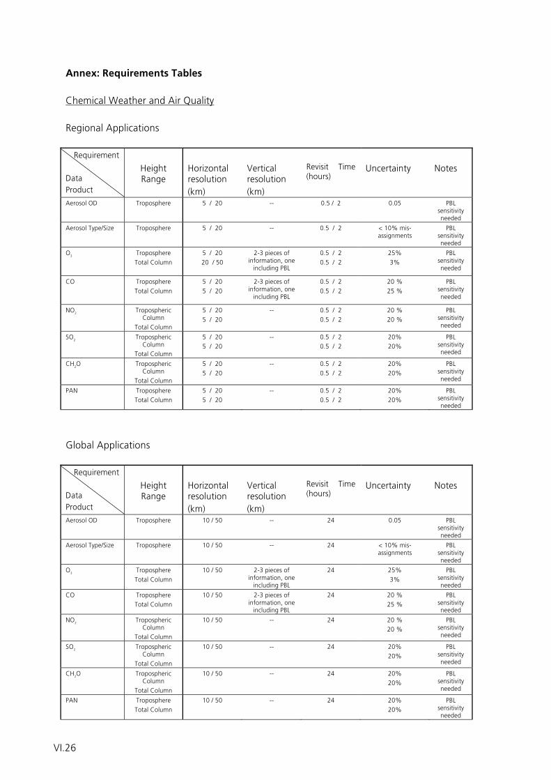
Annex: Requirements Tables Chemical Weather and Air Quality Regional Applications Requirement
Data Product
Height Range
Horizontal resolution (km)
Vertical resolution (km)
Revisit Time (hours)
Uncertainty
Notes
Aerosol OD Troposphere 5 / 20 -- 0.5 / 2 0.05 PBL sensitivity needed
Aerosol Type/Size Troposphere
5 / 20 -- 0.5 / 2 < 10% mis-assignments
PBL sensitivity needed
O3 Troposphere Total Column
5 / 20 20 / 50
2-3 pieces of information, one including PBL
0.5 / 2 0.5 / 2
25% 3%
PBL sensitivity needed
CO Troposphere Total Column
5 / 20 5 / 20
2-3 pieces of information, one including PBL
0.5 / 2 0.5 / 2
20 % 25 %
PBL sensitivity needed
NO2 Tropospheric Column
Total Column
5 / 20 5 / 20
-- 0.5 / 2 0.5 / 2
20 % 20 %
PBL sensitivity needed
SO2 Tropospheric Column
Total Column
5 / 20 5 / 20
-- 0.5 / 2 0.5 / 2
20% 20%
PBL sensitivity needed
CH2O Tropospheric Column
Total Column
5 / 20 5 / 20
-- 0.5 / 2 0.5 / 2
20% 20%
PBL sensitivity needed
PAN Troposphere Total Column
5 / 20 5 / 20
-- 0.5 / 2 0.5 / 2
20% 20%
PBL sensitivity needed
Global Applications Requirement
Data Product
Height Range
Horizontal resolution (km)
Vertical resolution (km)
Revisit Time (hours)
Uncertainty
Notes
Aerosol OD Troposphere 10 / 50 -- 24 0.05 PBL sensitivity needed
Aerosol Type/Size Troposphere
10 / 50 -- 24 < 10% mis-assignments
PBL sensitivity needed
O3 Troposphere Total Column
10 / 50 2-3 pieces of information, one including PBL
24 25% 3%
PBL sensitivity needed
CO Troposphere Total Column
10 / 50 2-3 pieces of information, one including PBL
24 20 % 25 %
PBL sensitivity needed
NO2 Tropospheric Column
Total Column
10 / 50 -- 24 20 % 20 %
PBL sensitivity needed
SO2 Tropospheric Column
Total Column
10 / 50 -- 24 20% 20%
PBL sensitivity needed
CH2O Tropospheric Column
Total Column
10 / 50 -- 24 20% 20%
PBL sensitivity needed
PAN Troposphere Total Column
10 / 50 -- 24 20% 20%
PBL sensitivity needed
VI.26
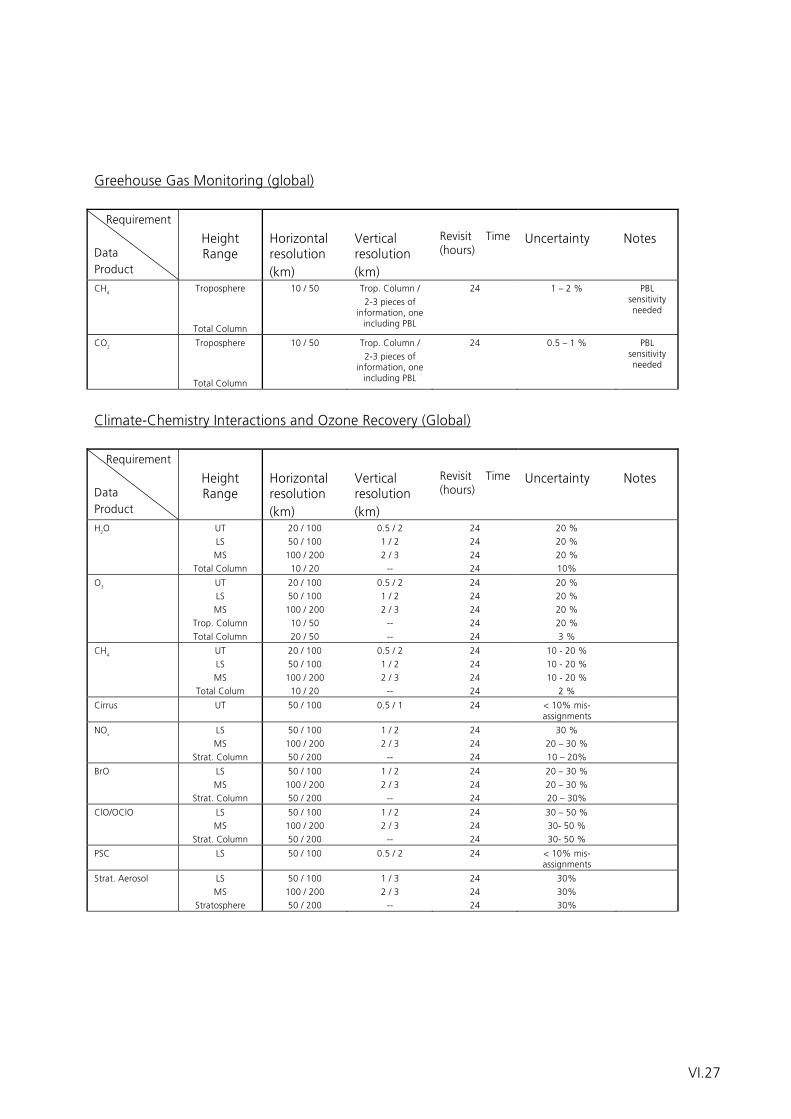
Greehouse Gas Monitoring (global) Requirement
Data Product
Height Range
Horizontal resolution (km)
Vertical resolution (km)
Revisit Time (hours)
Uncertainty
Notes
CH4 Troposphere
Total Column
10 / 50 Trop. Column / 2-3 pieces of
information, one including PBL
24 1 – 2 % PBL sensitivity needed
CO2 Troposphere
Total Column
10 / 50 Trop. Column / 2-3 pieces of
information, one including PBL
24 0.5 – 1 % PBL sensitivity needed
Climate-Chemistry Interactions and Ozone Recovery (Global) Requirement
Data Product
Height Range
Horizontal resolution (km)
Vertical resolution (km)
Revisit Time (hours)
Uncertainty
Notes
H2O UT LS MS
Total Column
20 / 100 50 / 100 100 / 200 10 / 20
0.5 / 2 1 / 2 2 / 3 --
24 24 24 24
20 % 20 % 20 % 10%
O3 UT LS MS
Trop. Column Total Column
20 / 100 50 / 100 100 / 200 10 / 50 20 / 50
0.5 / 2 1 / 2 2 / 3 -- --
24 24 24 24 24
20 % 20 % 20 % 20 % 3 %
CH4 UT LS MS
Total Colum
20 / 100 50 / 100 100 / 200 10 / 20
0.5 / 2 1 / 2 2 / 3 --
24 24 24 24
10 - 20 % 10 - 20 % 10 - 20 %
2 %
Cirrus UT 50 / 100 0.5 / 1 24 < 10% mis-assignments
NOx LS MS
Strat. Column
50 / 100 100 / 200 50 / 200
1 / 2 2 / 3 --
24 24 24
30 % 20 – 30 % 10 – 20%
BrO LS MS
Strat. Column
50 / 100 100 / 200 50 / 200
1 / 2 2 / 3 --
24 24 24
20 – 30 % 20 – 30 % 20 – 30%
ClO/OClO LS MS
Strat. Column
50 / 100 100 / 200 50 / 200
1 / 2 2 / 3 --
24 24 24
30 – 50 % 30- 50 % 30- 50 %
PSC LS 50 / 100 0.5 / 2 24 < 10% mis-assignments
Strat. Aerosol LS MS
Stratosphere
50 / 100 100 / 200 50 / 200
1 / 3 2 / 3 --
24 24 24
30% 30% 30%
VI.27

VI.28
Working Group
Hydrology
Participants:
W. Mauser, Uni München (Chair)
V. Hochschild, Uni Tübingen
S. Knabe, BfG
W. Kusch, DWD
T. Mohr, WMO
H. Staudenrausch, DLR Bonn
C. Thiel, Uni Jena
VI.29

VI.30
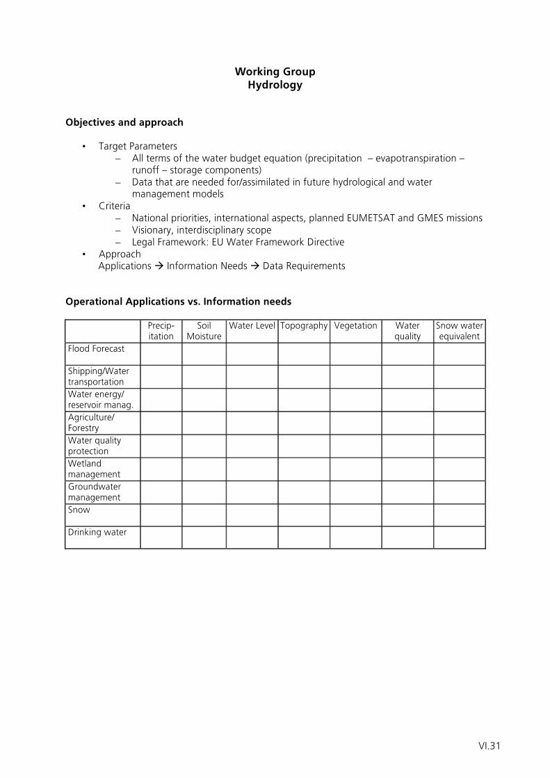
Working Group Hydrology
Objectives and approach
• Target Parameters – All terms of the water budget equation (precipitation – evapotranspiration –
runoff – storage components) – Data that are needed for/assimilated in future hydrological and water
management models • Criteria
– National priorities, international aspects, planned EUMETSAT and GMES missions – Visionary, interdisciplinary scope – Legal Framework: EU Water Framework Directive
• Approach Applications Information Needs Data Requirements Operational Applications vs. Information needs
���������� Precip-itation
Soil Moisture
Water Level Topography Vegetation Water quality
Snow water equivalent
Flood Forecast ����������
����������
���������� ���������� ���������� ���������� ����������
Shipping/Water transportation
����������
����������
���������� ���������� ���������� ���������� ����������
Water energy/ reservoir manag.
����������
����������
���������� ���������� ���������� ���������� ����������
Agriculture/ Forestry
����������
����������
���������� ���������� ���������� ���������� ����������
Water quality protection
����� ����������
���������� ���������� ���������� ���������� ����������
Wetland management
����������
����������
���������� ���������� ���������� ���������� ����������
Groundwater management
����������
����������
���������� ���������� ���������� ���������� ����������
Snow ����������
����������
���������� ���������� ���������� ���������� ����������
Drinking water ����������
���������
���������� ���������� ���������� ���������� ����������
VI.31
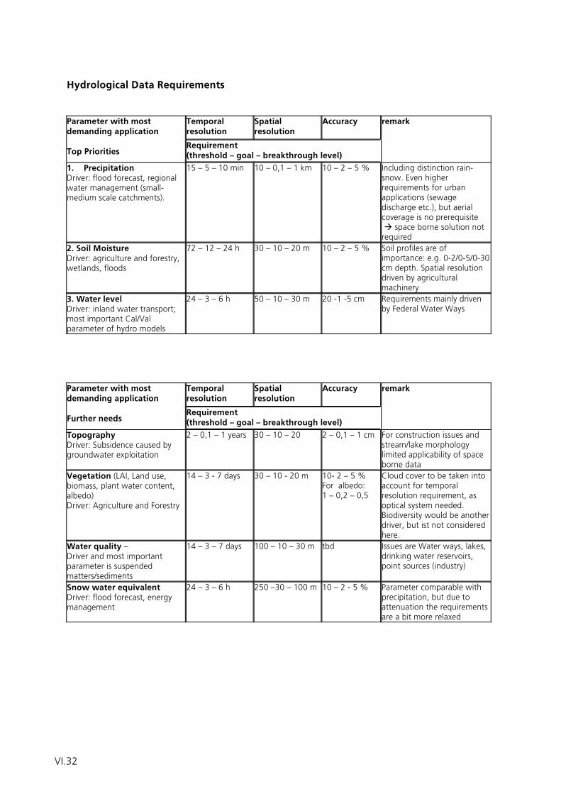
Hydrological Data Requirements
Temporal resolution
Spatial resolution
Accuracy Parameter with most demanding application Top Priorities
Requirement (threshold – goal – breakthrough level)
remark
1. Precipitation Driver: flood forecast, regional water management (small-medium scale catchments).
15 – 5 – 10 min 10 – 0,1 – 1 km 10 – 2 – 5 % Including distinction rain-snow. Even higher requirements for urban applications (sewage discharge etc.), but aerial coverage is no prerequisite space borne solution not required
2. Soil Moisture Driver: agriculture and forestry, wetlands, floods
72 – 12 – 24 h 30 – 10 – 20 m 10 – 2 – 5 % Soil profiles are of importance: e.g. 0-2/0-5/0-30 cm depth. Spatial resolution driven by agricultural machinery
3. Water level Driver: inland water transport; most important Cal/Val parameter of hydro models
24 – 3 – 6 h 50 – 10 – 30 m 20 -1 -5 cm Requirements mainly driven by Federal Water Ways
Temporal resolution
Spatial resolution
Accuracy Parameter with most demanding application Further needs
Requirement (threshold – goal – breakthrough level)
remark
Topography Driver: Subsidence caused by groundwater exploitation
2 – 0,1 – 1 years 30 – 10 – 20 2 – 0,1 – 1 cm For construction issues and stream/lake morphology limited applicability of space borne data
Vegetation (LAI, Land use, biomass, plant water content, albedo) Driver: Agriculture and Forestry
14 – 3 - 7 days 30 – 10 - 20 m 10- 2 – 5 % For albedo: 1 – 0,2 – 0,5
Cloud cover to be taken into account for temporal resolution requirement, as optical system needed. Biodiversity would be another driver, but ist not considered here.
Water quality – Driver and most important parameter is suspended matters/sediments
14 – 3 – 7 days 100 – 10 – 30 m tbd Issues are Water ways, lakes, drinking water reservoirs, point sources (industry)
Snow water equivalent Driver: flood forecast, energy management
24 – 3 – 6 h 250 –30 – 100 m 10 – 2 - 5 % Parameter comparable with precipitation, but due to attenuation the requirements are a bit more relaxed
VI.32
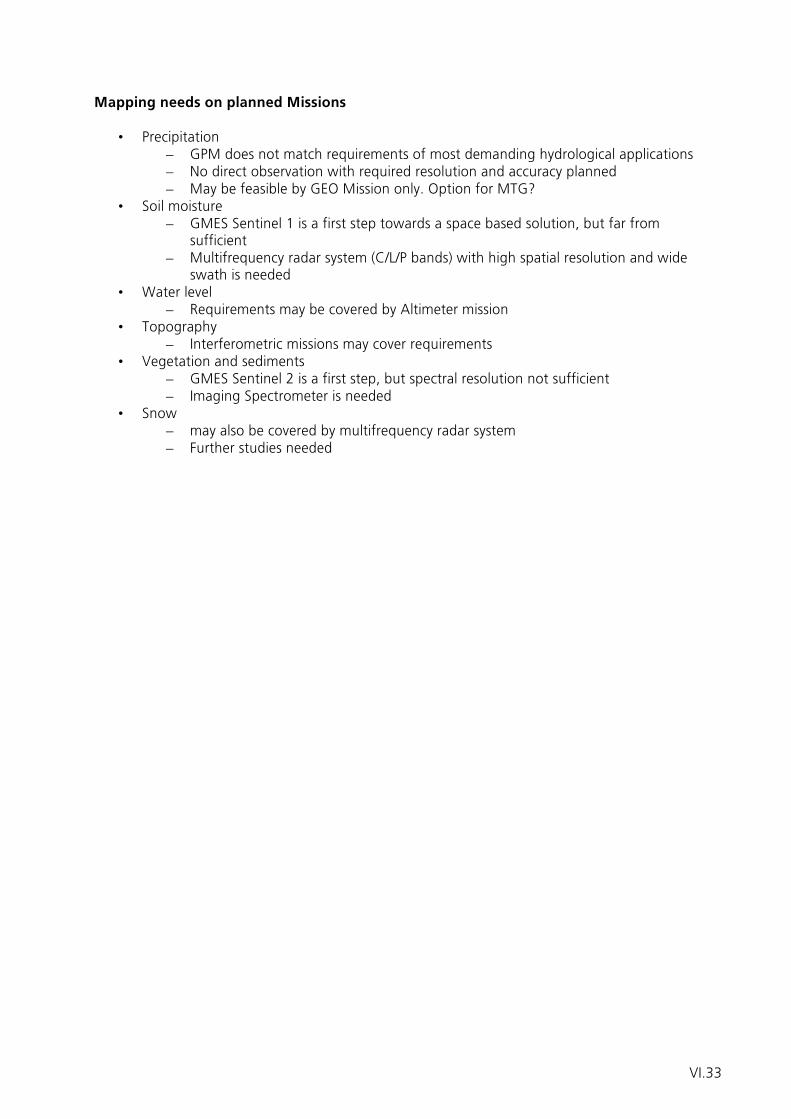
Mapping needs on planned Missions
• Precipitation – GPM does not match requirements of most demanding hydrological applications – No direct observation with required resolution and accuracy planned – May be feasible by GEO Mission only. Option for MTG?
• Soil moisture – GMES Sentinel 1 is a first step towards a space based solution, but far from
sufficient – Multifrequency radar system (C/L/P bands) with high spatial resolution and wide
swath is needed • Water level
– Requirements may be covered by Altimeter mission • Topography
– Interferometric missions may cover requirements • Vegetation and sediments
– GMES Sentinel 2 is a first step, but spectral resolution not sufficient – Imaging Spectrometer is needed
• Snow – may also be covered by multifrequency radar system – Further studies needed
VI.33

VI.34
Working Group
Climate
Participants:
H. Graßl, MPI Hamburg (Chair)
J.P. Burrows, IUP Uni. Bremen
Ch. Brüns, DLR Bonn
B. Fladt, EADS Astrium
A. Gratzki, DWD
S. Grünler, Uni Jena
A. Macke, IFM GEOMAR
B. Mayer, DLR
R. Preusker, FU Berlin
R. Schricke, EADS Astrium
H. Stark, ESA
R. Strobel, JenaOptronik
J. Schulz, DWD
VI.35

VI.36
Working Group Climate
1 Introduction The need to understand the natural processes, which determine climate and in particular the modification of climate resulting from anthropogenic activity, is an essential part of modern hypothesis driven earth system science. The observation of climate variables provides unique and objective knowledge about the system comprising the sun, the atmosphere and the earth. This is needed by policymakers to attribute accurately the origins of global climate change and to assess the natural variability and impact of anthropogenic emissions on the environment. In order to improve our understanding of the earth’s climate and its response to the consequences of an increasing population and standard of living, long term regional and global measurements of key parameters and atmospheric constituents are required. In the last 20 years Europe, led by a significant contribution from the German national agencies, scientists, industry, and their international partners, has developed a variety of successful atmospheric remote sensing measurement techniques. These have been deployed from the ground and successfully from orbiting satellite platforms. A series of research satellites has demonstrated the capability to measure key atmospheric and surface parameters as well as the constituents, required for atmospheric chemistry and climate research. Examples of the first retrievals of the global distributions of the greenhouse gases Methane and Carbon Dioxide, retrieved from space based observations, are shown in figure 1 and 2. These have been derived from the national research project SCIAMACHY, which flies aboard the ESA ENVISAT. The continuity of these new data sets is a national, European and international priority. Since 1999 the Deutsche Wetterdienst has been leading the Satellite Application Facility on Climate Monitoring (CM-SAF). The latter is part of the EUMETSAT distributed ground segment and is a consortium of 6 national meteorological services. Currently, CM-SAF focuses on atmospheric parameters related to the energy and water cycle. The CM-SAF produces or will produce climate data sets from instrumentation on (semi-) operational satellite platforms such as EUMETSAT’s MetOp and Meteosat Second Generation (MSG) as well as U.S. NOAA and the DMSP polar orbiters. Some examples of CM-SAF cloud products derived from the SEVIRI instrument onboard the MSG satellite are shown in figure 3. The production of climate data sets within the CM-SAF follows the GCOS climate monitoring principles and assures full traceability as a result of the established operational environment. 2 Scope of the Climate Sub-group Meeting This National User Workshop meeting to discuss an Operational Satellite System for Earth Monitoring was called together by the DWD and DLR. It brought together expertise in climate research from the observational and modeling communities in Germany. National representatives from scientific research, operational meteorology and industry came together in response to the DLR and DWD invitation to discuss the developments, needs and progress towards an Observational System for all aspects of Monitoring the Earth System. The central theme of the workshop addressed the post Meteosat Second Generation System, MSG, the Meteosat Third Generation, MTG, and the post EPS system as well as potential national involvement in the GMES. The sub group for climate was asked to identify priorities for these themes. This comprises both operational and scientific goals as well as national strategic interests.
VI.37
3 Climate Sub Group Discussions The Climate sub group discussions focused on the requirements for a Global Observing system with respect to Climate parameters. The following summarizes the discussion and the recommendations from the sub group, as presented by Professor Grassl. 3.1 Relevant Recent European Developments A European operational observation system, required for numerical weather prediction and nowcasting, has been developed and has been improving in the last 25 years. After initially being developed by ESA, the responsibility for the satellite contribution to this system has been mandated by the European Governments and their Meteorological Services to EUMETSAT and its partners. EUMETSAT, ESA and their national partners have worked together to develop and remove deficits in its observational capability through the Meteosat Second Generation, MSG, Satellites in geostationary earth orbit, GEO, and the upcoming series of polar orbiting MetOp satellites carrying instruments to monitor the atmosphere, ocean, ice, and land systems. The European operational space operator EUMETSAT has introduced the concept of a distributed ground segment in which the expertise of national meteorological services and science institutions throughout Europe has been combined to strengthen developments in the sector of Earth system remote sensing. This resulted in the foundation of eight Satellite Application Facilities on diverse themes ranging from Nowcasting to Climate Monitoring. Additionally, the improving observational capability has initiated the following emerging meteorological market areas, which are of great potential importance and significance, have much in common:
a) Atmospheric pollution and numerical environmental prediction or “chemical weather”
b) Greenhouse Gas Detection from Space and the Monitoring of international, European Treaties and Directives, as well as national laws.
These new objectives demand measurements of atmospheric constituents from space on a regular basis and the necessary ground segment to handle the data flow and provide Near Real Time analysis for short term prediction and long term climate research. Since the last national meeting at the Cloister Walberberg the charter of EUMETSAT has been enhanced to include climate monitoring and Germany taken a lead in this activity in Europe by establishing the Climate Monitoring SAF at DWD and the successful management of SCIAMACHY. However, the fate of the emerging market of numerical environmental prediction and its related impact on climate is not yet clear. Resources are required to sustain the communities involved in the new and emerging sectors of meteorology to provide the impetus for maintaining this are of internationally recognized expertise and related multiplicative wealth creation. 3.2 Climate monitoring objectives The overall objective for the climate aspect of an Earth Monitoring System is the generation of data sets of key climate parameters and atmospheric constituents, which describe well the earth climate and its variability. This data is required to assess the relative importance of the natural variability of climate and the impact of anthropogenic activity on global climate change. This overall objective is a long term undertaking as the derivation and attribution of trend as opposed to the observation of change in the system requires typically several decades of measurements.
VI.38
The accurate observation of climate requires a representative set of measurements. This in turn requires an adequate spatial resolution and temporal sampling. In summary, temporal and spatial scales able to detect diurnal, daily, weekly, monthly, seasonal, yearly, and decadal cycling at high spatial scales are required. In this context there is a very strong overlap with the objectives of the measurement of atmospheric pollution as envisaged in the IGOS (Integrated Global Observing Strategy) - IGACO (International Global Atmospheric Chemistry Observations) theme. Overarching Requirements of an Earth Monitoring System The operational space segment of an Earth Monitoring System has a variety of different objectives. It needs to measure key parameters and constituents, which describe effectively the climate and its variability and provide where possible early warning of potential hazards for the climate. There are several overarching requirements which need to be addressed by the observational system for climate monitoring:
i) The selection of an appropriate and adequate set of constituents and parameters to observe climate variability and to be used for attribution
ii) Accuracy of measurement sufficient to detect often small but significant short term and long term changes,
iii) The spatial and temporal sampling of the measurement must be representative,
iv) Long term continuity of the measurements coupled with improved measurement accuracy and sampling.
The Required Climate Variables and Sampling Strategy The Sub group for climate agreed that the following parameters for climate research are required to address the climate system (not in order of priority, not exclusive):
1) Temperature: a. Temperature profiles in the troposphere, stratosphere, mesosphere,
upper Air Temperature, b. Sea surface and land surface temperature.
2) Wind System: Horizontal and vertical winds at an adequate spatial resolution and sampling.
3) Momentum and Energy Fluxes.
4) Cloud Parameters: Water and ice cloud optical and microphysical properties, cloud top height, cloud cover, cloud optical thickness, cloud bottom, liquid and ice water content.
5) Precipitation: Global distribution over land and water, profile information
6) Aerosol Parameters: Aerosol optical thickness in UV, Visible and Short wave IR regions, aerosol extinction and absorption characteristics size and mass distribution and profile information.
7) Water Vapour: Total column amount and vertical profiles are required.
8) Greenhouse Gases: Carbon dioxide, CO2, Methane, CH4, Nitrous oxide, N2O.
9) Cryosphere: Sea Ice thickness and extent, Ice/Snow pack volume and mass, Glacier volume / mass.
VI.39
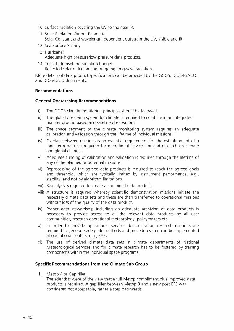
10) Surface radiation covering the UV to the near IR. 11) Solar Radiation Output Parameters:
Solar Constant and wavelength dependent output in the UV, visible and IR.
12) Sea Surface Salinity 13) Hurricane:
Adequate high pressure/low pressure data products,
14) Top-of-atmosphere radiation budget: Reflected solar radiation and outgoing longwave radiation.
More details of data product specifications can be provided by the GCOS, IGOS-IGACO, and IGOS-IGCO documents. Recommendations General Overarching Recommendations i) The GCOS climate monitoring principles should be followed.
ii) The global observing system for climate is required to combine in an integrated manner ground based and satellite observations
iii) The space segment of the climate monitoring system requires an adequate calibration and validation through the lifetime of individual missions.
iv) Overlap between missions is an essential requirement for the establishment of a long term data set required for operational services for and research on climate and global change.
v) Adequate funding of calibration and validation is required through the lifetime of any of the planned or potential missions.
vi) Reprocessing of the agreed data products is required to reach the agreed goals and threshold, which are typically limited by instrument performance, e.g., stability, and not by algorithm limitations.
vii) Reanalysis is required to create a combined data product.
viii) A structure is required whereby scientific demonstration missions initiate the necessary climate data sets and these are then transferred to operational missions without loss of the quality of the data product.
ix) Proper data stewardship including an adequate archiving of data products is necessary to provide access to all the relevant data products by all user communities, research operational meteorology, policymakers etc.
x) In order to provide operational services demonstration research missions are required to generate adequate methods and procedures that can be implemented at operational centers, e.g., SAFs.
xi) The use of derived climate data sets in climate departments of National Meteorological Services and for climate research has to be fostered by training components within the individual space programs.
Specific Recommendations from the Climate Sub Group 1. Metop 4 or Gap filler:
The scientists were of the view that a full Metop compliment plus improved data products is required. A gap filler between Metop 3 and a new post EPS was considered not acceptable, rather a step backwards.
VI.40
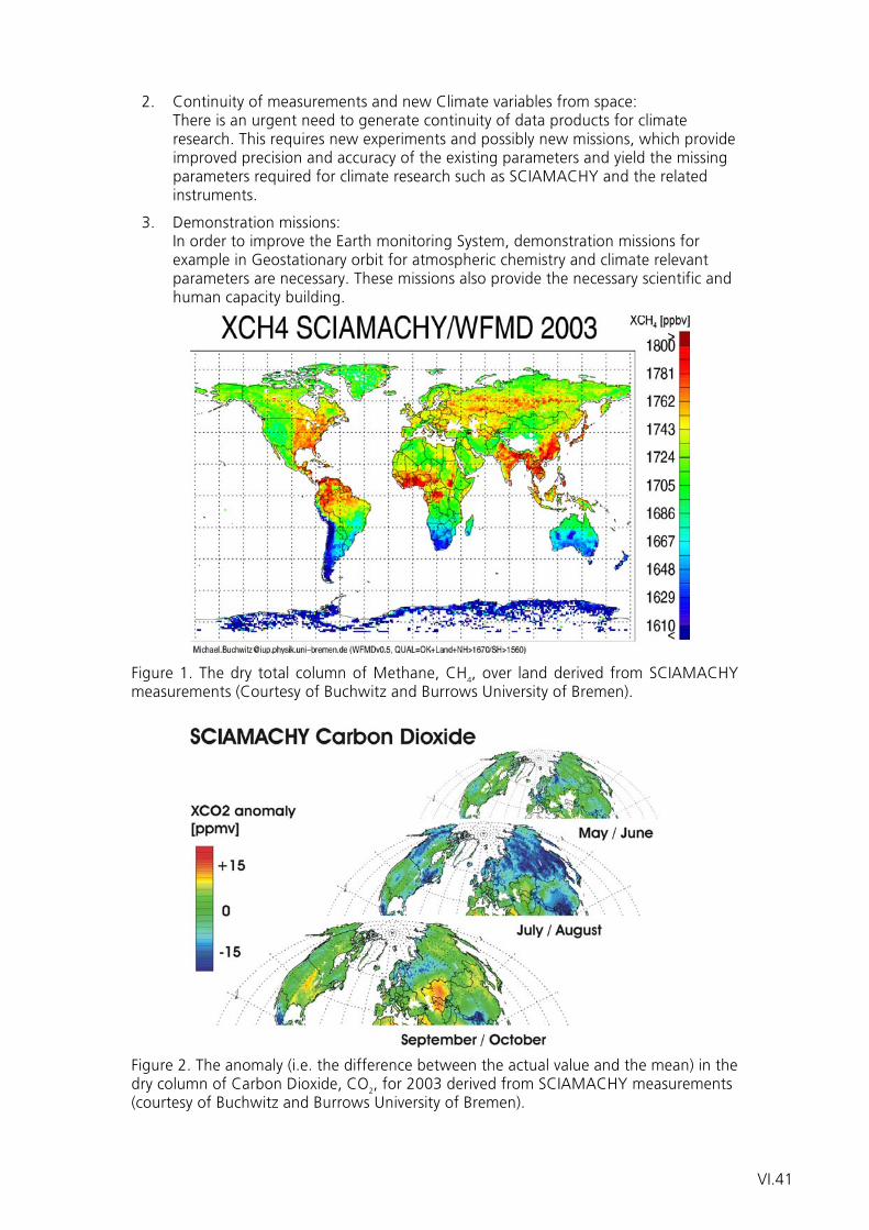
2. Continuity of measurements and new Climate variables from space: There is an urgent need to generate continuity of data products for climate research. This requires new experiments and possibly new missions, which provide improved precision and accuracy of the existing parameters and yield the missing parameters required for climate research such as SCIAMACHY and the related instruments.
3. Demonstration missions: In order to improve the Earth monitoring System, demonstration missions for example in Geostationary orbit for atmospheric chemistry and climate relevant parameters are necessary. These missions also provide the necessary scientific and human capacity building.
Figure 1. The dry total column of Methane, CH4, over land derived from SCIAMACHY measurements (Courtesy of Buchwitz and Burrows University of Bremen). Figure 2. The anomaly (i.e. the difference between the actual value and the mean) in the dry column of Carbon Dioxide, CO2, for 2003 derived from SCIAMACHY measurements (courtesy of Buchwitz and Burrows University of Bremen).
VI.41
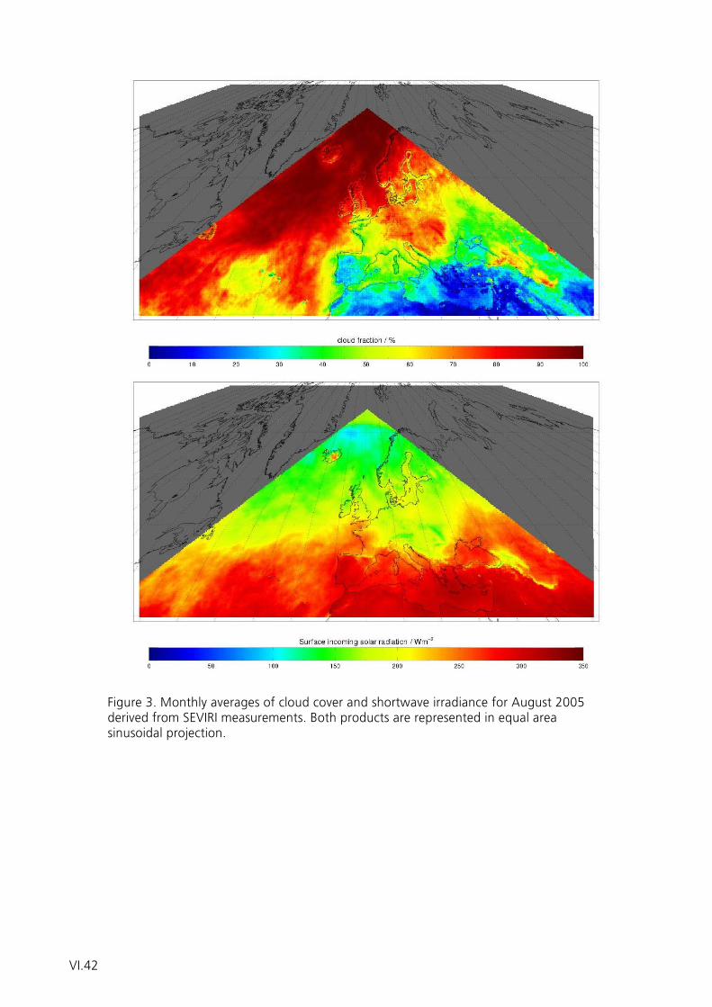
Figure 3. Monthly averages of cloud cover and shortwave irradiance for August 2005 derived from SEVIRI measurements. Both products are represented in equal area sinusoidal projection.
VI.42

Annex


Workshop Agenda
A.1

A.2
Nationaler Nutzerworkshop
zum Thema
Operationelle Satellitensysteme der Erdüberwachung
7. – 9. November 2005, Tagungsstätte Walberberg
Leitung: Prof. H. Graßl
Montag, 07. November 2005
11:00 – 14:00 Anmeldung
14:00 – 14:15 Eröffnung
Begrüßung durch den Vorstand des DLR Dr. L. Baumgarten, DLR
Begrüßung durch das BMVBW K. Trauernicht, BMVBW
Begrüßung durch den Präsidenten des DWD W. Kusch, DWD
14:15 – 14:45 Satelliten und das System Erde Prof. H. Graßl, MPI Hamburg
14:45 – 15:15 Das Global Earth Observation System U. Gärtnerof Systems, GEOSS
15:15 – 15:45 Planung von künftigen Satellitensystemen Prof. Jian Liu, WMOaußerhalb Europas
15:45 – 16:15 Kaffeepause
16:15 – 16:45 Das GMES-Weltraumsegment & relevante Prof. A. Ginati, ESAEarth-Explorer Missionen
16:45 – 17:15 Die MTG User-Requirements Dr. R. Stuhlmann, EUMETSAT
17:15 – 17:45 Ergebnisse der MTG Pre-Phase A Studien P. Bensi, ESA
17:45 – 18:00 Diskussion
18:30 Abendessen
20:00 Gemeinsame lockere Diskussion beim Tagesausklang im Clubraum
A.3
Dienstag, 08. November 2005
09:00 – 09:30 Aktuelle und geplante Aktivitäten zur E. Koenemann, EUMETSATVorbereitung des EPS-Nachfolgesystems
09:30 – 10:30 Technologische Analysen zu einem EPS-Nachfolgesystem
Das abbildende Radiometer MetImage Dr. B. Voss, JenaOptronik
Low-Cost EPS-Überbrückungssatellit Dr. H. Lübberstedt, OHB System
Post-EPS Initial Satellite (PEPSIS) Dr. R. Münzenmayer, Astrium
10:30 – 10:40 Vorstellung und Bildung der geplanten Arbeitsgruppen
10:40 – 11:00 Kaffeepause
11:00 – 12:30 Gruppenarbeit (Teil 1)
12:30 – 14:00 Mittagspause
14:00 – 15:30 Gruppenarbeit (Teil 2)
15:30 – 16:00 Kaffeepause
16:00 – 16:45 Zwischentreffen im Plenum: Kurzberichte der Arbeitsgruppen
¾ AG Unwetterwarnmanagement Dr. G. Steinhorst, DWD
¾ AG numerische Wettervorhersage Dr. N. Bormann, EZMW
¾ AG Ozean Prof. D. Stammer, Uni Hamburg
¾ AG Klima Prof. H. Graßl, MPI Hamburg
¾ AG Atmosphärenchemie Prof. H. Fischer, FZ Karlsruhe
¾ AG Hydrologie Prof. W. Mauser, Uni München
16:45 – 18:00 Gruppenarbeit (Teil 3)
18:30 Abendessen
20:00 Gemeinsame lockere Diskussion beim Tagesausklang im Clubraum
A.4
Mittwoch, 09. November 2005
08:30 – 09:15 Gruppenarbeit (Teil 4)
09:15 – 11:15 Präsentation und Diskussion der Ergebnisse der Gruppenarbeit
¾ AG Unwetterwarnmanagement Dr. G. Steinhorst, DWD
¾ AG numerische Wettervorhersage Dr. N. Bormann, EZMW
¾ AG Ozean Prof. D. Stammer, Uni Hamburg
¾ AG Klima Prof. H. Graßl, MPI Hamburg
¾ AG Atmosphärenchemie Prof. H. Fischer, FZ Karlsruhe
¾ AG Hydrologie Prof. W. Mauser, Uni München
11:15 – 11:45 Kaffeepause
11:45 – 13:00 Formulierung und Verabschiedung der Prof. H. Graßl, MPI HamburgEmpfehlungen des Workshops
13:00 Mittagessen & Workshop-Ende
A.5

A.6

Workshop Participants
A.7

A.8
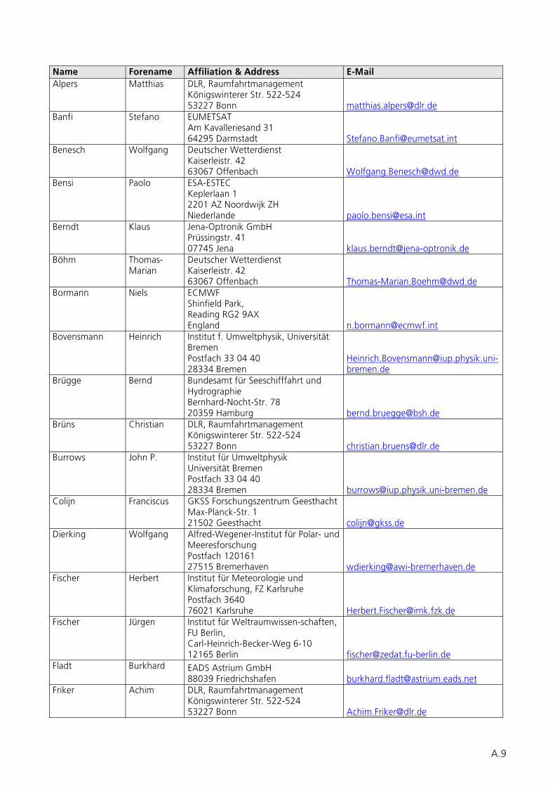
Name Forename Affiliation & Address E-Mail Alpers Matthias DLR, Raumfahrtmanagement
Königswinterer Str. 522-524 53227 Bonn [email protected]
Banfi Stefano EUMETSAT Am Kavalleriesand 31 64295 Darmstadt [email protected]
Benesch Wolfgang Deutscher Wetterdienst Kaiserleistr. 42 63067 Offenbach [email protected]
Bensi Paolo ESA-ESTEC Keplerlaan 1 2201 AZ Noordwijk ZH Niederlande [email protected]
Berndt Klaus Jena-Optronik GmbH Prüssingstr. 41 07745 Jena [email protected]
Böhm Thomas-Marian
Deutscher Wetterdienst Kaiserleistr. 42 63067 Offenbach [email protected]
Bormann Niels ECMWF Shinfield Park, Reading RG2 9AX England [email protected]
Bovensmann Heinrich Institut f. Umweltphysik, Universität Bremen Postfach 33 04 40 28334 Bremen
[email protected]bremen.de
Brügge Bernd Bundesamt für Seeschifffahrt und Hydrographie Bernhard-Nocht-Str. 78 20359 Hamburg [email protected]
Brüns Christian DLR, Raumfahrtmanagement Königswinterer Str. 522-524 53227 Bonn [email protected]
Burrows John P. Institut für Umweltphysik Universität Bremen Postfach 33 04 40 28334 Bremen [email protected]
Colijn Franciscus GKSS Forschungszentrum Geesthacht Max-Planck-Str. 1 21502 Geesthacht [email protected]
Dierking Wolfgang Alfred-Wegener-Institut für Polar- und Meeresforschung Postfach 120161 27515 Bremerhaven [email protected]
Fischer Herbert Institut für Meteorologie und Klimaforschung, FZ Karlsruhe Postfach 3640 76021 Karlsruhe [email protected]
Fischer Jürgen Institut für Weltraumwissen-schaften, FU Berlin, Carl-Heinrich-Becker-Weg 6-10 12165 Berlin [email protected]
Fladt Burkhard EADS Astrium GmbH 88039 Friedrichshafen [email protected]
Friker Achim DLR, Raumfahrtmanagement Königswinterer Str. 522-524 53227 Bonn [email protected]
A.9
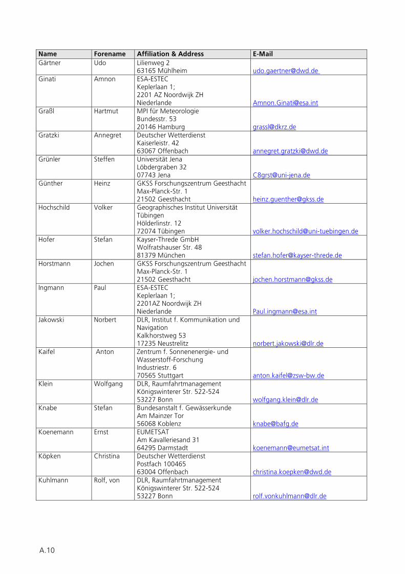
Name Forename Affiliation & Address E-Mail Gärtner Udo Lilienweg 2
63165 Mühlheim [email protected] Ginati Amnon ESA-ESTEC
Keplerlaan 1; 2201 AZ Noordwijk ZH Niederlande [email protected]
Graßl Hartmut MPI für Meteorologie Bundesstr. 53 20146 Hamburg [email protected]
Gratzki Annegret Deutscher Wetterdienst Kaiserleistr. 42 63067 Offenbach [email protected]
Grünler Steffen Universität Jena Löbdergraben 32 07743 Jena [email protected]
Günther Heinz GKSS Forschungszentrum Geesthacht Max-Planck-Str. 1 21502 Geesthacht [email protected]
Hochschild Volker Geographisches Institut Universität Tübingen Hölderlinstr. 12 72074 Tübingen [email protected]
Hofer Stefan Kayser-Threde GmbH Wolfratshauser Str. 48 81379 München [email protected]
Horstmann Jochen GKSS Forschungszentrum Geesthacht Max-Planck-Str. 1 21502 Geesthacht [email protected]
Ingmann Paul ESA-ESTEC Keplerlaan 1; 2201AZ Noordwijk ZH Niederlande [email protected]
Jakowski Norbert DLR, Institut f. Kommunikation und Navigation Kalkhorstweg 53 17235 Neustrelitz [email protected]
Kaifel Anton Zentrum f. Sonnenenergie- und Wasserstoff-Forschung Industriestr. 6 70565 Stuttgart [email protected]
Klein Wolfgang DLR, Raumfahrtmanagement Königswinterer Str. 522-524 53227 Bonn [email protected]
Knabe Stefan Bundesanstalt f. Gewässerkunde Am Mainzer Tor 56068 Koblenz [email protected]
Koenemann Ernst EUMETSAT Am Kavalleriesand 31 64295 Darmstadt [email protected]
Köpken Christina Deutscher Wetterdienst Postfach 100465 63004 Offenbach [email protected]
Kuhlmann Rolf, von DLR, Raumfahrtmanagement Königswinterer Str. 522-524 53227 Bonn [email protected]
A.10
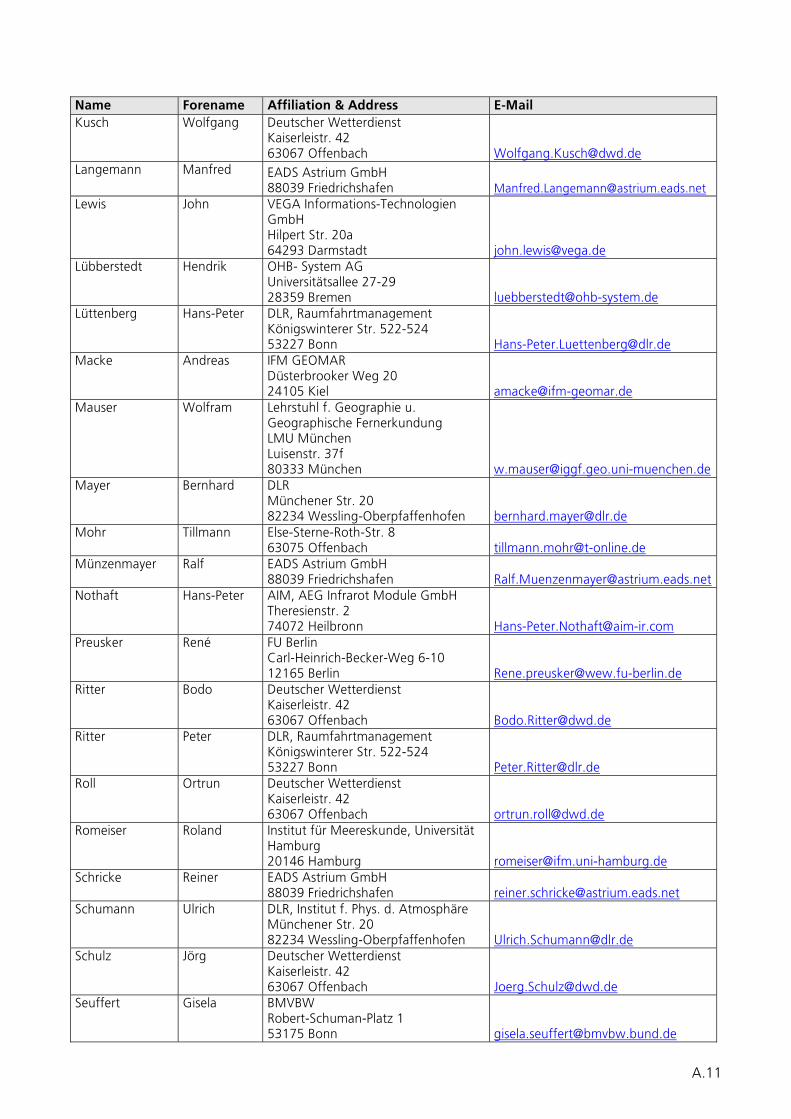
Name Forename Affiliation & Address E-Mail Kusch Wolfgang Deutscher Wetterdienst
Kaiserleistr. 42 63067 Offenbach [email protected]
Langemann Manfred EADS Astrium GmbH 88039 Friedrichshafen [email protected]
Lewis John VEGA Informations-Technologien GmbH Hilpert Str. 20a 64293 Darmstadt [email protected]
Lübberstedt Hendrik OHB- System AG Universitätsallee 27-29 28359 Bremen [email protected]
Lüttenberg Hans-Peter DLR, Raumfahrtmanagement Königswinterer Str. 522-524 53227 Bonn [email protected]
Macke Andreas IFM GEOMAR Düsterbrooker Weg 20 24105 Kiel [email protected]
Mauser Wolfram Lehrstuhl f. Geographie u. Geographische Fernerkundung LMU München Luisenstr. 37f 80333 München [email protected]
Mayer Bernhard DLR Münchener Str. 20 82234 Wessling-Oberpfaffenhofen [email protected]
Mohr Tillmann Else-Sterne-Roth-Str. 8 63075 Offenbach [email protected]
Münzenmayer Ralf EADS Astrium GmbH 88039 Friedrichshafen [email protected]
Nothaft Hans-Peter AIM, AEG Infrarot Module GmbH Theresienstr. 2 74072 Heilbronn [email protected]
Preusker René FU Berlin Carl-Heinrich-Becker-Weg 6-10 12165 Berlin [email protected]
Ritter Bodo Deutscher Wetterdienst Kaiserleistr. 42 63067 Offenbach [email protected]
Ritter Peter DLR, Raumfahrtmanagement Königswinterer Str. 522-524 53227 Bonn [email protected]
Roll Ortrun Deutscher Wetterdienst Kaiserleistr. 42 63067 Offenbach [email protected]
Romeiser Roland Institut für Meereskunde, Universität Hamburg 20146 Hamburg [email protected]
Schricke Reiner EADS Astrium GmbH 88039 Friedrichshafen [email protected]
Schumann Ulrich DLR, Institut f. Phys. d. Atmosphäre Münchener Str. 20 82234 Wessling-Oberpfaffenhofen [email protected]
Schulz Jörg Deutscher Wetterdienst Kaiserleistr. 42 63067 Offenbach [email protected]
Seuffert Gisela BMVBW Robert-Schuman-Platz 1 53175 Bonn [email protected]
A.11
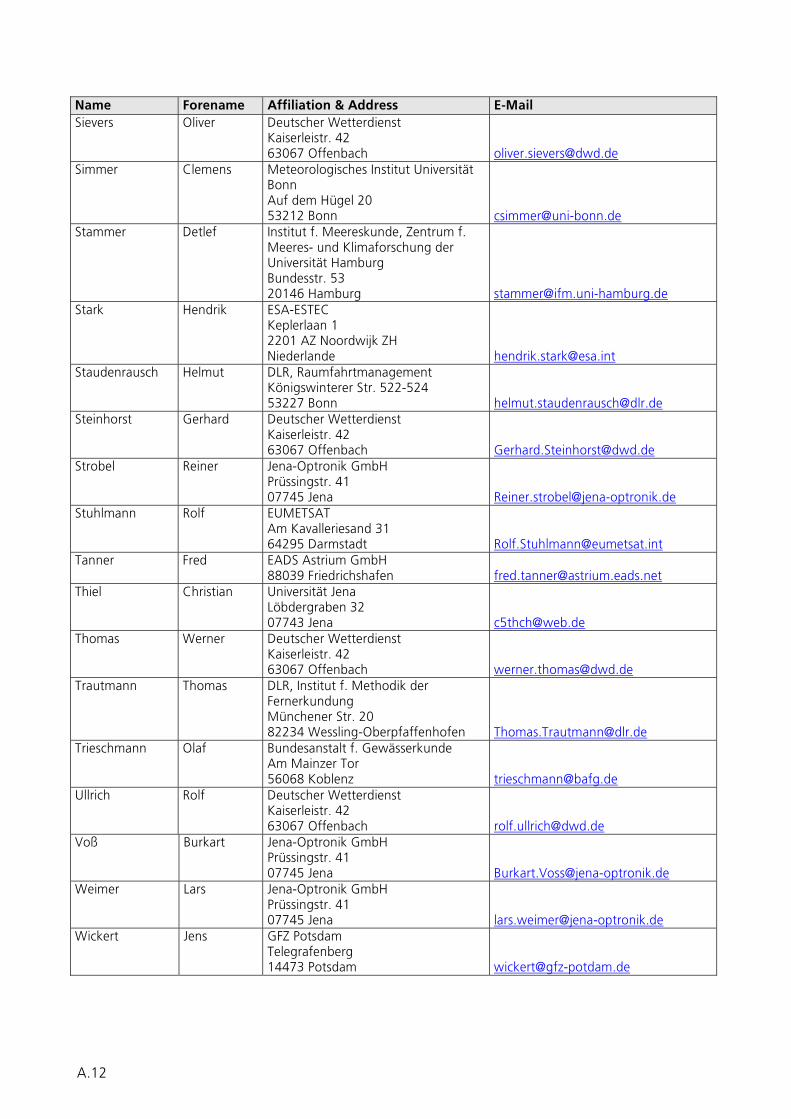
Name Forename Affiliation & Address E-Mail Sievers Oliver Deutscher Wetterdienst
Kaiserleistr. 42 63067 Offenbach [email protected]
Simmer Clemens Meteorologisches Institut Universität Bonn Auf dem Hügel 20 53212 Bonn [email protected]
Stammer Detlef Institut f. Meereskunde, Zentrum f. Meeres- und Klimaforschung der Universität Hamburg Bundesstr. 53 20146 Hamburg [email protected]
Stark Hendrik ESA-ESTEC Keplerlaan 1 2201 AZ Noordwijk ZH Niederlande [email protected]
Staudenrausch Helmut DLR, Raumfahrtmanagement Königswinterer Str. 522-524 53227 Bonn [email protected]
Steinhorst Gerhard Deutscher Wetterdienst Kaiserleistr. 42 63067 Offenbach [email protected]
Strobel Reiner Jena-Optronik GmbH Prüssingstr. 41 07745 Jena [email protected]
Stuhlmann Rolf EUMETSAT Am Kavalleriesand 31 64295 Darmstadt [email protected]
Tanner Fred EADS Astrium GmbH 88039 Friedrichshafen [email protected]
Thiel Christian Universität Jena Löbdergraben 32 07743 Jena [email protected]
Thomas Werner Deutscher Wetterdienst Kaiserleistr. 42 63067 Offenbach [email protected]
Trautmann Thomas DLR, Institut f. Methodik der Fernerkundung Münchener Str. 20 82234 Wessling-Oberpfaffenhofen [email protected]
Trieschmann Olaf Bundesanstalt f. Gewässerkunde Am Mainzer Tor 56068 Koblenz [email protected]
Ullrich Rolf Deutscher Wetterdienst Kaiserleistr. 42 63067 Offenbach [email protected]
Voß Burkart Jena-Optronik GmbH Prüssingstr. 41 07745 Jena [email protected]
Weimer Lars Jena-Optronik GmbH Prüssingstr. 41 07745 Jena [email protected]
Wickert Jens GFZ Potsdam Telegrafenberg 14473 Potsdam [email protected]
A.12


![REFERENCIAS BIBLIOGRÁFICAS...215 [35] LUPFERT, E. et al.; Concentrator Testing; DLR Deutsches Zentrum fur Luft- und Raumfahrt e.V., NREL Trough Workshop; Golden Denver, 2007 [36]](https://img.pdfslide.us/doc/110x75/60d49e51fe53cb2713273fd9/referencias-bibliogr-215-35-lupfert-e-et-al-concentrator-testing-dlr.jpg)