Embed Size (px)
Citation preview
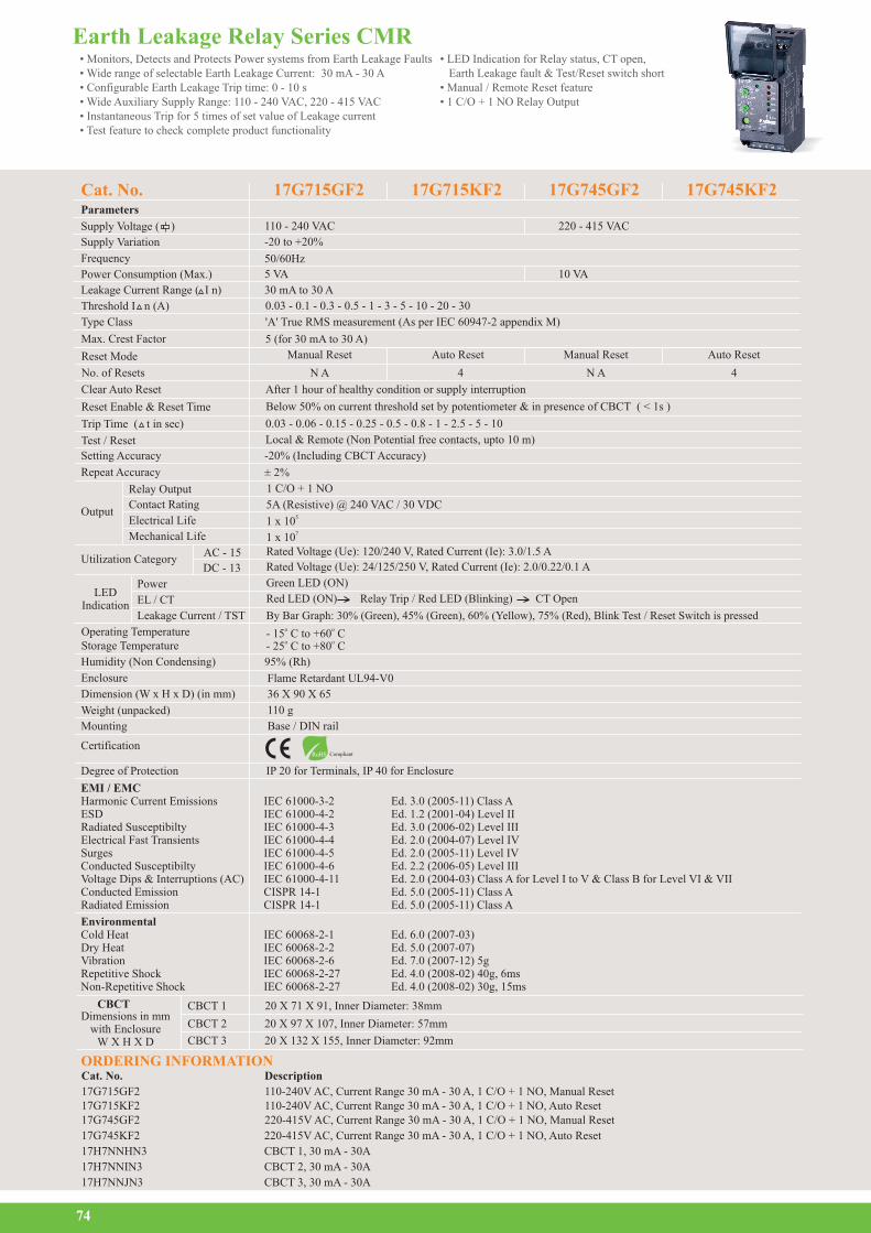
• Monitors, Detects and Protects Power systems from Earth Leakage Faults • Wide range of selectable Earth Leakage Current: 30 mA - 30 A• Configurable Earth Leakage Trip time: 0 - 10 s • Wide Auxiliary Supply Range: 110 - 240 VAC, 220 - 415 VAC • Instantaneous Trip for 5 times of set value of Leakage current• Test feature to check complete product functionality
• LED Indication for Relay status, CT open, Earth Leakage fault & Test/Reset switch short • Manual / Remote Reset feature • 1 C/O + 1 NO Relay Output
Cat. No.Parameters
Power Consumption (Max.)
220 - 415 VAC
50/60Hz
17G715GF2 17G745GF2
110 - 240 VAC
-20 to +20%
10 VA 5 VA
30 mA to 30 A
17G715KF2 17G745KF2
Earth Leakage Relay Series CMR
74
Supply Voltage ( )
Supply Variation
Frequency
ORDERING INFORMATION
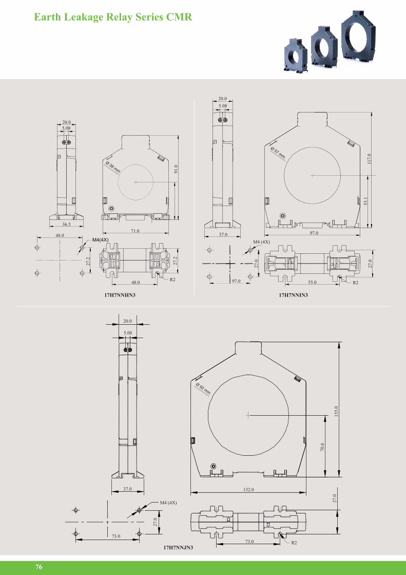
CBCT
CBCT 3
CBCT 2
CBCT 1Dimensions in mm
with EnclosureW X H X D
20 X 71 X 91, Inner Diameter: 38mm
20 X 97 X 107, Inner Diameter: 57mm
20 X 132 X 155, Inner Diameter: 92mm
Leakage Current Range ( I n)
Reset Mode
No. of Resets 4N A N A 4
Clear Auto Reset After 1 hour of healthy condition or supply interruption
Reset Enable & Reset Time Below 50% on current threshold set by potentiometer & in presence of CBCT ( < 1s )
Manual Reset Manual ResetAuto Reset Auto Reset
Threshold I n (A) 0.03 - 0.1 - 0.3 - 0.5 - 1 - 3 - 5 - 10 - 20 - 30
Type Class 'A' True RMS measurement (As per IEC 60947-2 appendix M)
Max. Crest Factor 5 (for 30 mA to 30 A)
Test / Reset Local & Remote (Non Potential free contacts, upto 10 m)
Trip Time ( t in sec) 0.03 - 0.06 - 0.15 - 0.25 - 0.5 - 0.8 - 1 - 2.5 - 5 - 10
-20% (Including CBCT Accuracy)
± 2%
Setting Accuracy
Repeat Accuracy
Utilization Category AC - 15
DC - 13
Rated Voltage (Ue): 120/240 V, Rated Current (Ie): 3.0/1.5 A
Rated Voltage (Ue): 24/125/250 V, Rated Current (Ie): 2.0/0.22/0.1 A
51 x 10 71 x 10
5A (Resistive) @ 240 VAC / 30 VDC
1 C/O + 1 NORelay Output
OutputContact Rating
Electrical Life
Mechanical Life
Humidity (Non Condensing) 95% (Rh)
Operating Temperature Storage Temperature
o o- 15 C to +60 Co o- 25 C to +80 C
Degree of Protection IP 20 for Terminals, IP 40 for Enclosure
CertificationRoHS Compliant
Enclosure Flame Retardant UL94-V0
Dimension (W x H x D) (in mm) 36 X 90 X 65 110 g Weight (unpacked)
Mounting Base / DIN rail
Green LED (ON)Power
Leakage Current / TST
EL / CT Red LED (ON) Relay Trip / Red LED (Blinking) CT Open
By Bar Graph: 30% (Green), 45% (Green), 60% (Yellow), 75% (Red), Blink Test / Reset Switch is pressed
LED Indication
Cat. No. Description
17G715GF2 110-240V AC, Current Range 30 mA - 30 A, 1 C/O + 1 NO, Manual Reset17G715KF2 110-240V AC, Current Range 30 mA - 30 A, 1 C/O + 1 NO, Auto Reset17G745GF2 220-415V AC, Current Range 30 mA - 30 A, 1 C/O + 1 NO, Manual Reset
17G745KF2 220-415V AC, Current Range 30 mA - 30 A, 1 C/O + 1 NO, Auto Reset
17H7NNHN3 CBCT 1, 30 mA - 30A
17H7NNIN3 CBCT 2, 30 mA - 30A
17H7NNJN3 CBCT 3, 30 mA - 30A
EMI / EMCHarmonic Current Emissions IEC 61000-3-2 Ed. 3.0 (2005-11) Class AESD IEC 61000-4-2 Ed. 1.2 (2001-04) Level IIRadiated Susceptibilty IEC 61000-4-3 Ed. 3.0 (2006-02) Level III Electrical Fast Transients IEC 61000-4-4 Ed. 2.0 (2004-07) Level IV Surges IEC 61000-4-5 Ed. 2.0 (2005-11) Level IVConducted Susceptibilty IEC 61000-4-6 Ed. 2.2 (2006-05) Level IIIVoltage Dips & Interruptions (AC) IEC 61000-4-11 Ed. 2.0 (2004-03) Class A for Level I to V & Class B for Level VI & VIIConducted Emission CISPR 14-1 Ed. 5.0 (2005-11) Class ARadiated Emission CISPR 14-1 Ed. 5.0 (2005-11) Class A
EnvironmentalCold Heat IEC 60068-2-1 Ed. 6.0 (2007-03)Dry Heat IEC 60068-2-2 Ed. 5.0 (2007-07)Vibration IEC 60068-2-6 Ed. 7.0 (2007-12) 5gRepetitive Shock IEC 60068-2-27 Ed. 4.0 (2008-02) 40g, 6msNon-Repetitive Shock IEC 60068-2-27 Ed. 4.0 (2008-02) 30g, 15ms
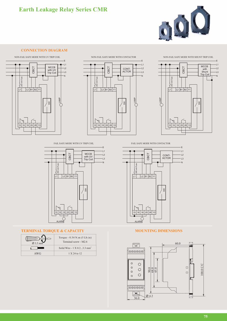
CONNECTION DIAGRAM
Earth Leakage Relay Series CMR
75
MOUNTING DIMENSIONSTERMINAL TORQUE & CAPACITY
FAIL SAFE MODE WITH CONTACTOR
CB
CT
SW
ALARM
15 16 18 Y2
L1
L2
L1
E
L3
N
Y1B2B1L2
25 28
25
0 m
A F
use
CONT-ACTOR
FAIL SAFE MODE WITH UV TRIP COIL
CB
CT
SW
ALARM
15 16 18 Y2
L1 Y1B2B1L2
25 28
25
0 m
A F
use
MCCBwith UVTrip Coil
L2
L1
E
L3
N
NON-FAIL SAFE MODE WITH CONTACTOR
L2
L1
E
L3
N
LA
MP
SW
15 16 18 Y2
L1 Y1B2B1L2
25 28
25
0 m
A F
use
CONT-ACTORC
BC
T
NON-FAIL SAFE MODE WITH UV TRIP COIL
CB
CT
L2
L1
E
L3
N
LA
MP
SW
15 16 18 Y2
L1 Y1B2B1L2
25 28
25
0 m
A F
use
CB
CT MCCB
with UVTrip Coil
NON-FAIL SAFE MODE WITH SHUNT TRIP COIL
L2
L1
E
L3
N
LA
MP
SW
15 16 18 Y2
L1 Y1B2B1L2
25 28
25
0 m
A F
use
CB
CT MCCB
with Shunt
Trip Coil
Ø 3.5 mmTerminal screw - M2.6
Torque - 0.54 N.m (5 Lb.in)
Solid Wire - 21 X 0.2...3.3 mm
1 X 24 to 12AWG
60.0
90.0
68.0
45.0
36.0Ø 4.2
100.
0 C
/C
Earth Leakage Relay Series CMR
76
17H7NNIN3
37.0 97.0
M4 (4X)
97.0 55.0 R2
27.0
27.0
117.
053
.1
20.0
5.08
Ø 57 mm
17H7NNHN3
48.0
48.0
36.5
71.0
R2
20.05.08
27.2
27.2
91.0
Ø 38 mm
17H7NNJN3
20.0
132.0
73.073.0
37.0
5.08
M4 (4X)
R2
155.
0
70.6
27.0
27.0
Ø 92 mm