Embed Size (px)
Citation preview

According to the copyright and the civil
law,the reproduction of this catalogue, or
any part of this one, by electronic, mecha-
nical methods, by means of photocopies,
microfilms, recordings or other, is perem-
ptorily forbidden. Rights are reserved for
all countries.
Drawings, specifications and reference
numbers may be modified and changed.
CONTREL s.r.l reserves itself the right, to
make changes for technical or quality
improvements, without any notice.
April 2009
www.
CONTREL elettronica s.r.l. • Via San Fereolo 9, 26900 LODITel. +39 0371 30207 • Fax +39 0371 32819
e-mail: [email protected] • www.contrel.it
e le t t ron i ca
ISO 9001:20009105-C035
EARTH LEAKAGE RELAY
STATIC RELAY FOR MOTOR RE-START
AND REACCELERATION
RELAY FOR PERMANENT CONTROLOF THE MCCB’S TRIPPING CIRCUIT
AND ACTUATOR FOR SAFETY CIRCUITS
© C
ontr
el e
lettr
onic
a -
tutti
i di
ritti
ris
erva
ti -
finito
di s
tam
pare
Apr
ile 2
009
conc
ept
| des
ign
| pho
to |
ww
w.n
eod
os.it
microener.com
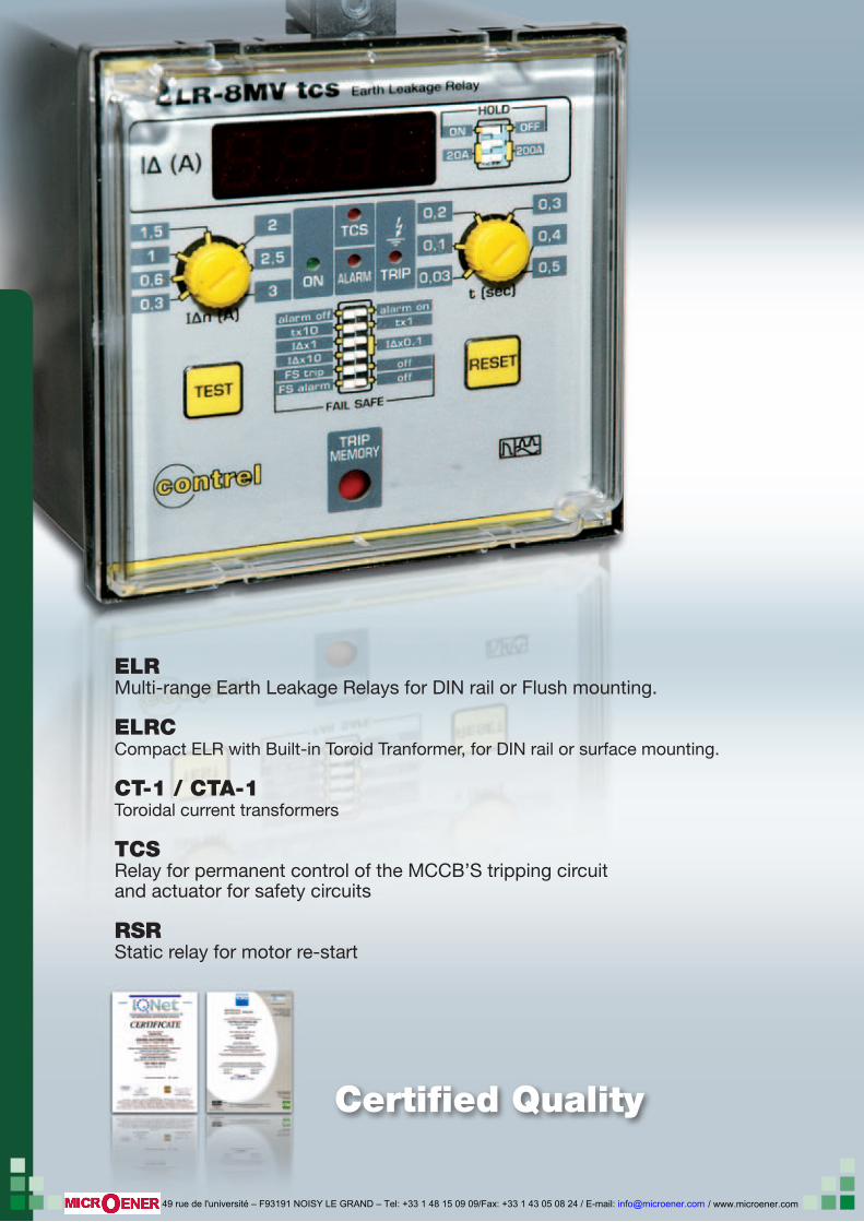
ELRMulti-range Earth Leakage Relays for DIN rail or Flush mounting.
ELRCCompact ELR with Built-in Toroid Tranformer, for DIN rail or surface mounting.
CT-1 / CTA-1Toroidal current transformers TCSRelay for permanent control of the MCCB’S tripping circuit and actuator for safety circuits
RSRStatic relay for motor re-start
Certified Quality
/ www.microener.com 49 rue de l'université – F93191 NOISY LE GRAND – Tel: +33 1 48 15 09 09/Fax: +33 1 43 05 08 24 / E-mail: [email protected]
1
indice
PRODUCTS PAGE
IIIII EARTH LEAKAGE RELAY
DIN RAIL MOUNTING VERSION ELR-3C 2ELR-3F 4ELR-3E 6ELR-61 . ELR-m61 . ELR-62 . ELR-m62 8
“COMPACT” VERSION WITH BUIT-IN TOROIDAL TRANSFORMER FOR DIN RAIL MOUNTING ELRC-B 10
DIN RAIL MOUNTING. WITH AUTOMATIC TRIP AND RECLOSING FOR CONTROLLING THE EARTH LEAKAGE INPUBLIC LIGHTING,REFRIGERATION ROOMS,TRAFFIC LIGHTS AND SIMILAR UNATTENDED INSTALLATIONS ELRD-L . ELRD-L2m . ELRC-BL 12
“COMPACT” VERSION WITH BUILT-IN TOROIDAL TRANSFORMER ELRC-1 16
FLUSH MOUNTING VERSION DIN 48X48 mmELR-7 18
FLUSH MOUNTING VERSIONS DIN 48X96 mmELR-4o . ELR-m4o . ELR-4v . ELR-m4v 20
FLUSH MOUNTING VERSION DIN 72X72 mmELR-91 . ELR-92 22
FLUSH MOUNTING VERSION DIN 96X96 mm WITH REDUCED DEPTH ENCLOSURESELR-1E . ELR-2 . ELR-2M 26
FLUSH MOUNTING VERSION DIN 96X96 mm WITH ADVANCED FUNCTIONSELR-8V . ELR-8tcs . ELR-8MVtcs 30
EARTH LEAKAGE RELAY - FLUSH MOUNTING VERSION DIN 96x96 mm WITHSELF-POWER FOR SMALL NETWORKS INTERRUPTION, FAIL SAFE, ETC.ELR-51 . ELR-m51 . ELR-52 . ELR-m52 34
SELECTION TABLE 36
IIIII MULTIFUNCTIONAL AMMETER MEASURING NETWORK’S DIFFERENTIALS CURRENT
FLUSH MOUNTING DIN 96X96 mm ELM-4 37
IIIII CURRENT TOROIDAL TRANSFORMERS
CT-1 38CT1M . CT1S - SPECIAL TOROIDAL TRANSFORMERS 40CTD-1/28, CT-1/35,CT-1/60,CT-1/80,CT-1/110,CT-1/160,CTA-1/160 40CTA-1/110, CT-1/210, CTA-1/210, CT-1/415 41
IIIII RELAY FOR PERMANENT CONTROL OF THE MCCB’S TRIPPING CIRCUIT TCS 1, TCS 2, TCS 3, TCS 4, 44
IIIII ACTUATOR FOR SAFETY CIRCUIT
TCS-A5 48
IIII STATIC RELAY FOR MOTOR RE-START AND REACCELARATION
RSR-72 51
24
6
8
10
12
16
18
22
20
26
30
37
34
38
44
48
51
/ www.microener.com 49 rue de l'université – F93191 NOISY LE GRAND – Tel: +33 1 48 15 09 09/Fax: +33 1 43 05 08 24 / E-mail: [email protected]
2
RESET
A M
tx10 tx1
x1
x10x0,1
RESET
A M
tx10 tx1
x1
x10x0,1
TESTRESET
ELR-3C
I (A)Δ0,25
0,5
1 1,5
2
2,5 0,02
0,1
0,2 0,3
0,4
0,5Δt(s)
ON TRIP
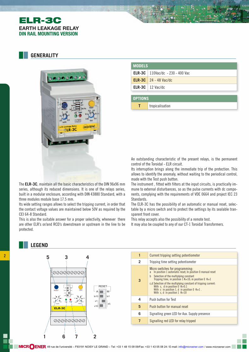
The ELR-3C, maintain all the basic characteristics of the DIN 96x96 mm series, although its reduced dimensions. It is one of the relays series, built in a modular enclosure, according with DIN 43880 Standard, with a three modules module base 17.5 mm. Its wide setting ranges allows to select the tripping current, in order that the contact voltage values are maintained below 50V as required by the CEI 64-8 Standard.This is also the suitable answer for a proper selectivity, whenever there are other ELR’s or/and RCD’s downstream or upstream in the line to be protected.
An outstanding characteristic of the present relays, is the permanent control of the Toroidal - ELR circuit.Its interruption brings along the immediate trip of the protection. This allows to identify the anomaly, without waiting to the periodical control, made with the Test push button.The instrument , fitted with filters at the input circuits, is practically im-mune to external disturbances, so as the pulse currents with dc compo-nents, complying with the requirements of VDE 0664 and project IEC 23 Standards.The ELR-3C has the possibility of an automatic or manual reset, selec-table by a micro switch and to protect the settings by its sealable tran-sparent front cover.This relay accepts also the possibility of a remote test.It may also be coupled to any of our CT-1 Toroidal Transformers.
ELR-3CEARTH LEAKAGE RELAYDIN RAIL MOUNTING VERSION
GENERALITY
LEGEND
OPTIONS
T tropicalisation
MODELS
ELR-3C 110Vac/dc - 230 - 400 Vac
ELR-3C 24 - 48 Vac/dc
ELR-3C 12 Vac/dc
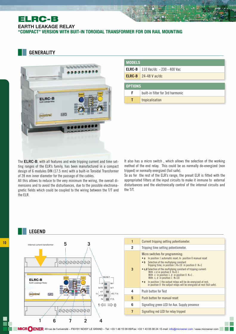
1 Current tripping setting potentiometer
2 Tripping time setting potentiometer
3
Micro switches for programming:a In position 1 automatic reset; In position 0 manual resetb Selection of the multiplying constant Tripping time, in position 1 K=10; in position 0 K=1c,d Selection of the multiplying constant of tripping current: With c, d in position 0 K=0.1 With c in position 1, d in position 0 K=1 . With c, d in position 1 K=10
4 Push button for Test
5 Push button for manual reset
6 Signalling green LED for Aux. Supply presence
7 Signalling red LED for relay tripped
4
7 2
3
6
5
1
/ www.microener.com 49 rue de l'université – F93191 NOISY LE GRAND – Tel: +33 1 48 15 09 09/Fax: +33 1 43 05 08 24 / E-mail: [email protected]
3 3
LOAD
Aux
N R S TSUPPLY
Ba
Earth
12
14
161718
12
M ON
Reset
x1 x10
x10M
Test
I ∆I ∆0,02÷0,5
10 7 5 3 1
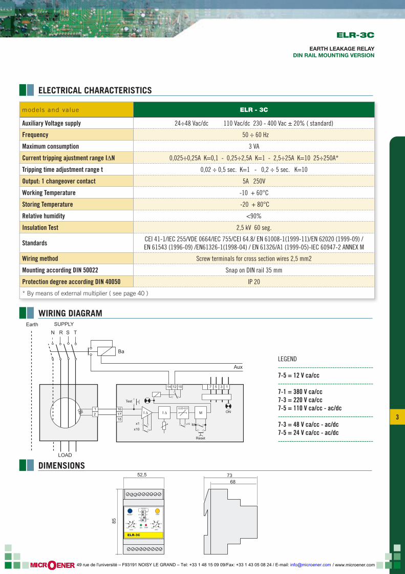
mode ls and va lue ELR - 3C
Auxiliary Voltage supply 24÷48 Vac/dc 110 Vac/dc 230 - 400 Vac ± 20% ( standard)
Frequency 50 ÷ 60 Hz
Maximum consumption 3 VA
Current tripping ajustment range I∆N 0,025÷0,25A K=0,1 - 0,25÷2,5A K=1 - 2,5÷25A K=10 25÷250A*
Tripping time adjustment range t 0,02 ÷ 0,5 sec. K=1 - 0,2 ÷ 5 sec. K=10
Output: 1 changeover contact 5A 250V
Working Temperature -10 + 60°C
Storing Temperature -20 + 80°C
Relative humidity <90%
Insulation Test 2,5 kV 60 seg.
Standards CEI 41-1/IEC 255/VDE 0664/IEC 755/CEI 64.8/ EN 61008-1(1999-11)/EN 62020 (1999-09) /EN 61543 (1996-09) /EN61326-1(1998-04) / EN 61326/A1 (1999-05)-IEC 60947-2 ANNEX M
Wiring method Screw terminals for cross section wires 2,5 mm2
Mounting according DIN 50022 Snap on DIN rail 35 mm
Protection degree according DIN 40050 IP 20
* By means of external multiplier ( see page 40 )
ELECTRICAL CHARACTERISTICS
WIRING DIAGRAM
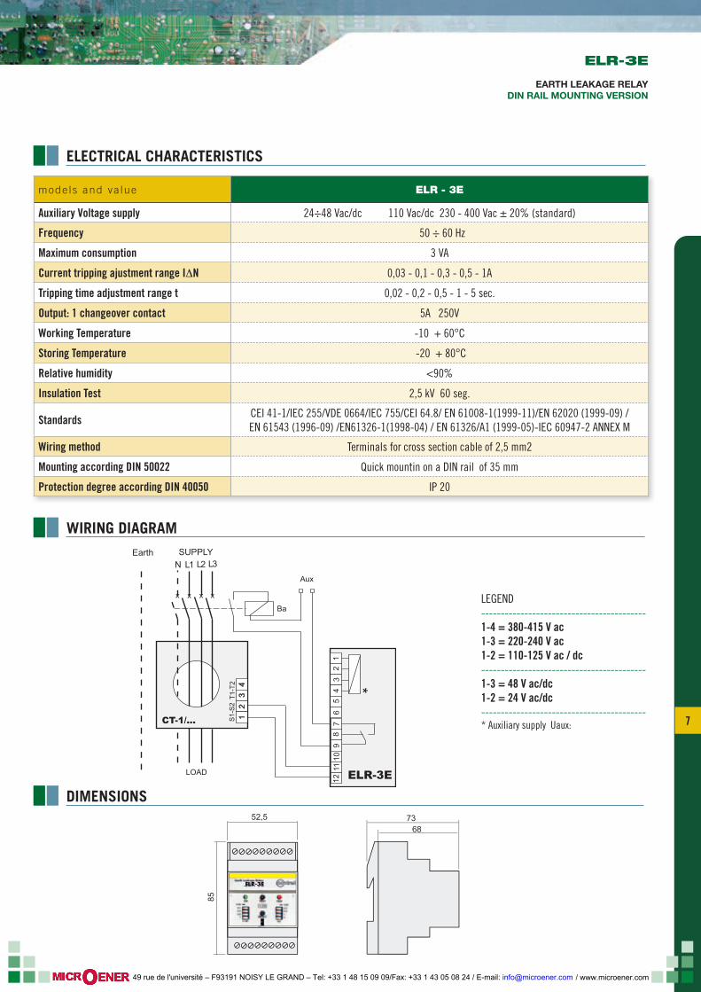
DIMENSIONS 73
6852,5
85
RESET
A M
tx10 tx1
x1
x10x0,1
TESTRESET
ELR-3C
I (A)Δ0,25
0,5
1 1,5
2
2,5 0,02
0,1
0,2 0,3
0,4
0,5Δt(s)
ON TRIP
ELR-3C
EARTH LEAKAGE RELAYDIN RAIL MOUNTING VERSION
LEGEND------------------------------------------7-5 = 12 V ca/cc------------------------------------------7-1 = 380 V ca/cc7-3 = 220 V ca/cc7-5 = 110 V ca/cc - ac/dc------------------------------------------7-3 = 48 V ca/cc - ac/dc7-5 = 24 V ca/cc - ac/dc------------------------------------------
/ www.microener.com 49 rue de l'université – F93191 NOISY LE GRAND – Tel: +33 1 48 15 09 09/Fax: +33 1 43 05 08 24 / E-mail: [email protected]
4
LEGEND
OPTIONS
T tropicalisation
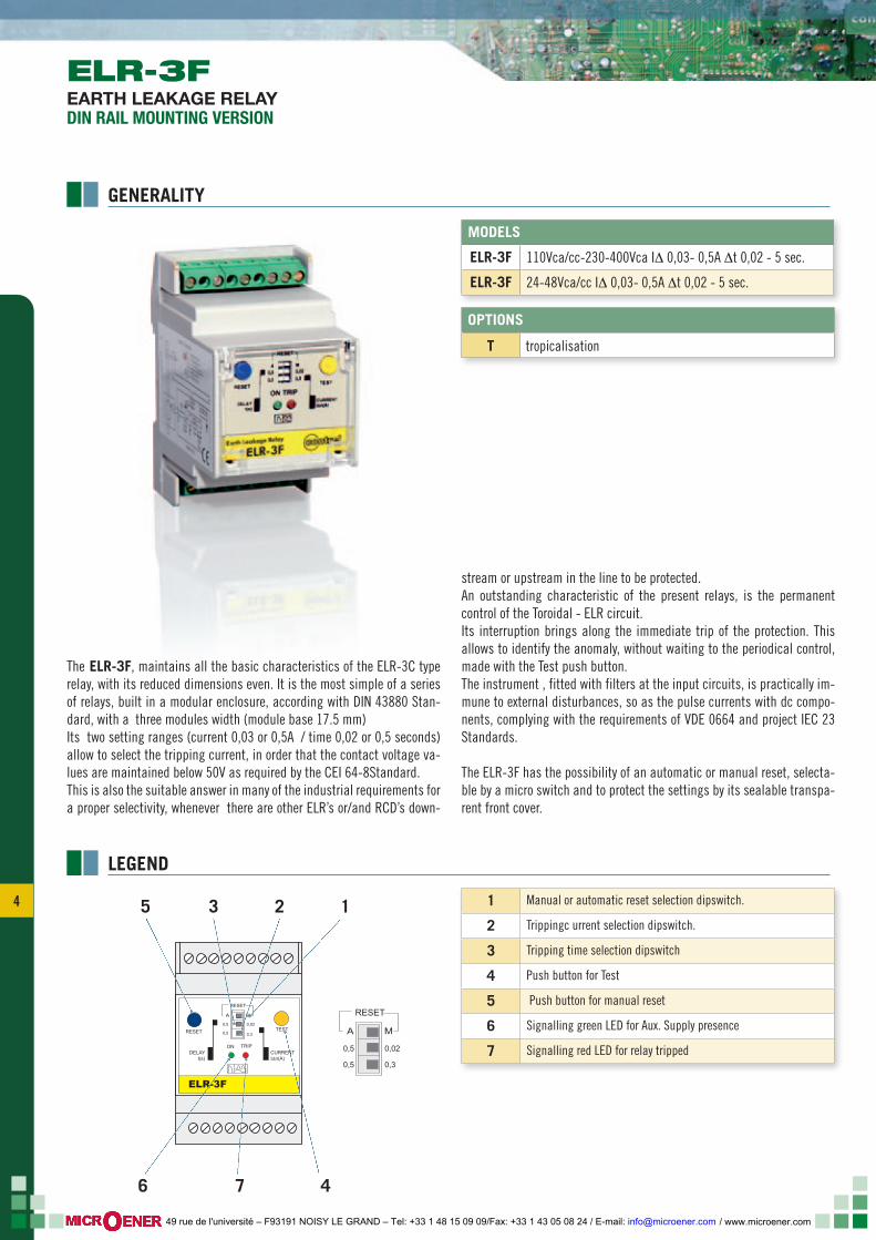
MODELS
ELR-3F 110Vca/cc-230-400Vca I∆ 0,03- 0,5A ∆t 0,02 - 5 sec.
ELR-3F 24-48Vca/cc I∆ 0,03- 0,5A ∆t 0,02 - 5 sec.
1 Manual or automatic reset selection dipswitch.
2 Trippingc urrent selection dipswitch.
3 Tripping time selection dipswitch
4 Push button for Test
5 Push button for manual reset
6 Signalling green LED for Aux. Supply presence
7 Signalling red LED for relay tripped
The ELR-3F, maintains all the basic characteristics of the ELR-3C type relay, with its reduced dimensions even. It is the most simple of a series of relays, built in a modular enclosure, according with DIN 43880 Stan-dard, with a three modules width (module base 17.5 mm) Its two setting ranges (current 0,03 or 0,5A / time 0,02 or 0,5 seconds) allow to select the tripping current, in order that the contact voltage va-lues are maintained below 50V as required by the CEI 64-8Standard.This is also the suitable answer in many of the industrial requirements for a proper selectivity, whenever there are other ELR’s or/and RCD’s down-
stream or upstream in the line to be protected. An outstanding characteristic of the present relays, is the permanent control of the Toroidal - ELR circuit.Its interruption brings along the immediate trip of the protection. This allows to identify the anomaly, without waiting to the periodical control, made with the Test push button.The instrument , fitted with filters at the input circuits, is practically im-mune to external disturbances, so as the pulse currents with dc compo-nents, complying with the requirements of VDE 0664 and project IEC 23 Standards.
The ELR-3F has the possibility of an automatic or manual reset, selecta-ble by a micro switch and to protect the settings by its sealable transpa-rent front cover.
RESET
A M
0,5
0,5
0,02
0,3TESTRESET
DELAYt(s)
CURRENTΙΔn(A)
ELR-3F
ON TRIP
RESET
A M
0,5
0,5
0,3
0,02
1
7 4
3 2
6
5
ELR-3FEARTH LEAKAGE RELAYDIN RAIL MOUNTING VERSION
GENERALITY
/ www.microener.com 49 rue de l'université – F93191 NOISY LE GRAND – Tel: +33 1 48 15 09 09/Fax: +33 1 43 05 08 24 / E-mail: [email protected]
5 5
7368
52,5
85
RESET
A M
0,5
0,5
0,02
0,3TESTRESET
DELAYt(s)
CURRENTΙΔn(A)
ELR-3F
ON TRIP
Aux
N R S T
Ba
12
14
161718
12
M ON
Reset
x1 x10
x10M
Test
I ∆I ∆0,02÷0,5
10 7 5 3 1
LOAD
SUPPLYEarth
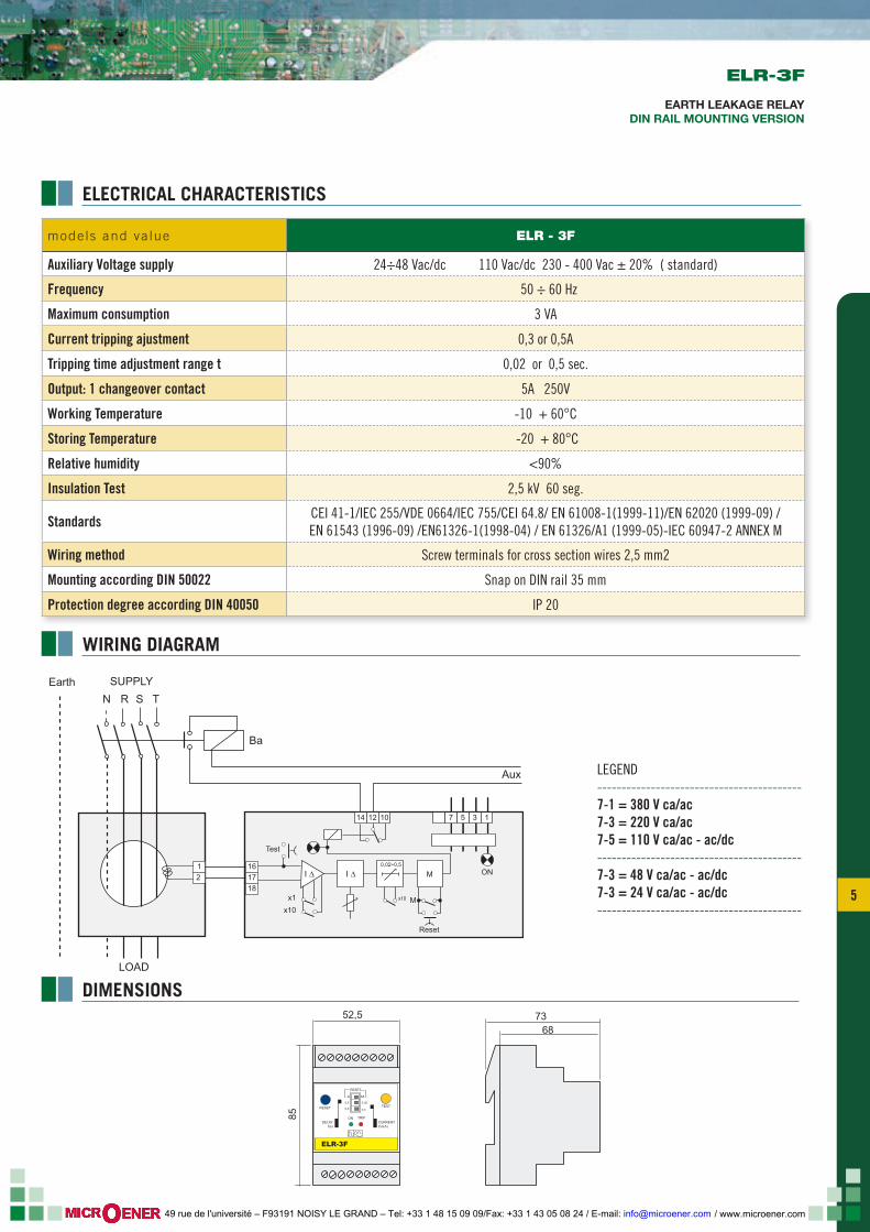
LEGEND------------------------------------------7-1 = 380 V ca/ac7-3 = 220 V ca/ac7-5 = 110 V ca/ac - ac/dc------------------------------------------7-3 = 48 V ca/ac - ac/dc7-3 = 24 V ca/ac - ac/dc------------------------------------------
ELECTRICAL CHARACTERISTICS
WIRING DIAGRAM
DIMENSIONS
ELR-3F
EARTH LEAKAGE RELAYDIN RAIL MOUNTING VERSION
mode ls and va lue ELR - 3F
Auxiliary Voltage supply 24÷48 Vac/dc 110 Vac/dc 230 - 400 Vac ± 20% ( standard)
Frequency 50 ÷ 60 Hz
Maximum consumption 3 VA
Current tripping ajustment 0,3 or 0,5A
Tripping time adjustment range t 0,02 or 0,5 sec.
Output: 1 changeover contact 5A 250V
Working Temperature -10 + 60°C
Storing Temperature -20 + 80°C
Relative humidity <90%
Insulation Test 2,5 kV 60 seg.
Standards CEI 41-1/IEC 255/VDE 0664/IEC 755/CEI 64.8/ EN 61008-1(1999-11)/EN 62020 (1999-09) /EN 61543 (1996-09) /EN61326-1(1998-04) / EN 61326/A1 (1999-05)-IEC 60947-2 ANNEX M
Wiring method Screw terminals for cross section wires 2,5 mm2
Mounting according DIN 50022 Snap on DIN rail 35 mm
Protection degree according DIN 40050 IP 20
/ www.microener.com 49 rue de l'université – F93191 NOISY LE GRAND – Tel: +33 1 48 15 09 09/Fax: +33 1 43 05 08 24 / E-mail: [email protected]
6
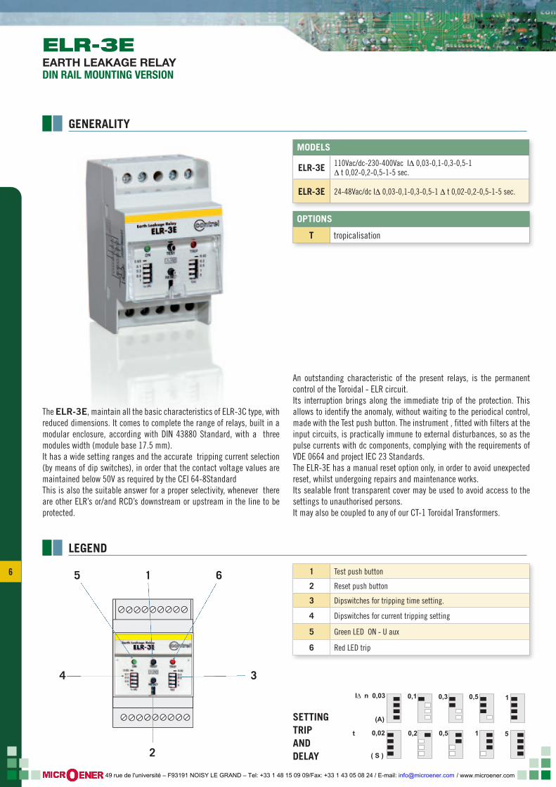
The ELR-3E, maintain all the basic characteristics of ELR-3C type, with reduced dimensions. It comes to complete the range of relays, built in a modular enclosure, according with DIN 43880 Standard, with a three modules width (module base 17.5 mm).It has a wide setting ranges and the accurate tripping current selection (by means of dip switches), in order that the contact voltage values are maintained below 50V as required by the CEI 64-8StandardThis is also the suitable answer for a proper selectivity, whenever there are other ELR’s or/and RCD’s downstream or upstream in the line to be protected.
An outstanding characteristic of the present relays, is the permanent control of the Toroidal - ELR circuit.Its interruption brings along the immediate trip of the protection. This allows to identify the anomaly, without waiting to the periodical control, made with the Test push button. The instrument , fitted with filters at the input circuits, is practically immune to external disturbances, so as the pulse currents with dc components, complying with the requirements of VDE 0664 and project IEC 23 Standards.The ELR-3E has a manual reset option only, in order to avoid unexpected reset, whilst undergoing repairs and maintenance works. Its sealable front transparent cover may be used to avoid access to the settings to unauthorised persons.It may also be coupled to any of our CT-1 Toroidal Transformers.
LEGEND
SETTING TRIP AND DELAY
OPTIONS
T tropicalisation
MODELS
ELR-3E 110Vac/dc-230-400Vac I∆ 0,03-0,1-0,3-0,5-1∆ t 0,02-0,2-0,5-1-5 sec.
ELR-3E 24-48Vac/dc I∆ 0,03-0,1-0,3-0,5-1 ∆ t 0,02-0,2-0,5-1-5 sec.
1 Test push button
2 Reset push button
3 Dipswitches for tripping time setting.
4 Dipswitches for current tripping setting
5 Green LED ON - U aux
6 Red LED trip
TARATURA CORRENTE E TEMPO DI INTERVENTO
I n 0,03
(A)
Δ 0,1 0,3 0,5
0,02 0,2 0,5 1 5
( S )
1
t
ELR-3EELELRELRELELELEEELLLLRRRRRRRRLRELRRLRELRELREELELREELELRELELRLRELRLLLLRRLRRELRRRRLRRREELRELRELRELRELRLLRLLRELRLLRRELRLRRRRELLRLLRLRLRELRRRELRELEEEEELRLLLRRRRLRRREEEELRLRLLRELRRELRLRELRELREEELRE RRRRRELREELRRLRRLRRELRELLLRRELRRRRRRLLELRRRRELELLRRRRRREELRLRRRREEELLRRRRREELLLRRLRRRRREEELRRRRREEELLLLLLRRREELLLLRLRRELRLRRELRRRRREEEEEEEELRLRLLLLLRRRRRR-3E-3E-3E3-33333333-3EEEEEEEEEE333E333E3-3E33E-3EEEE3EEE3EE3333E-3E3E-33E3-3EE3E333E3E3-3E3EEE3E333E3E3-3E33-3E3-3EE3EE3EE-3E3E333-333E-3E33EE3E3E3E-3E-33333333-3EE3E333-3EEEEEE3E3-333E3E3EE3EE333EEEE3E3E-3E-3---3EEE-3EE3E-3EEEEE-3-3333333E333333333E33EEE3EE333E33EE3333E33333E3333EEEEEEE3333
6
2
15
4 3
ELR-3EEARTH LEAKAGE RELAYDIN RAIL MOUNTING VERSION
GENERALITY
/ www.microener.com 49 rue de l'université – F93191 NOISY LE GRAND – Tel: +33 1 48 15 09 09/Fax: +33 1 43 05 08 24 / E-mail: [email protected]
7 7
LEGEND------------------------------------------1-4 = 380-415 V ac1-3 = 220-240 V ac1-2 = 110-125 V ac / dc------------------------------------------1-3 = 48 V ac/dc1-2 = 24 V ac/dc------------------------------------------* Auxiliary supply Uaux:
7368
52,5
85
ELR-3EELR-3ELELR-3ELR-3ELR-3ELR-3ELR-3ELRLLRRRLR 3333LR-3EELR 3EEELR-3ELRLR-3LR-3LLLLLELRRELR 3RELRRRR-3333LR-33EELRELR-3ELR-3ELR-3ELR-3LLLR-3LRELRR-RR 3333EELR-3ELRLRLLR-3LLLR-RELRRRLRR 33333R-33R-3EELR-3LLR 3RRRRELRELR-3RLR-3LR-333LR-3R 33EELR-3LRR 33ELRLLLR-3LLR-3RELRRRRR 33EELRLLR-3LRRR------3R-3ELREELLRRR-33R-3LRR-3RR----333R-3R-3EEELLRLRRRR 333R-333EEELLLR 3LLRR 33333EELRRRRRR 3333LLELRRRRR 33EEEELLR 333EEEEEEEEEEEEEEEEEEEEEEEEEEEEEEEEEEEEEEEEEEEEEEEEEEEEEEEEEEEEEEEEEEEEEEEEEEEEEEE
12
34
57
81
011
12
9
LOAD
N L1 L2 L3
Ba
Aux
*
12
34
ELR-3E
CT-1/...
x x x x
S1
-S2
T1
-T2
6
SUPPLYEarth
ELECTRICAL CHARACTERISTICS
WIRING DIAGRAM
DIMENSIONS
ELR-3E
EARTH LEAKAGE RELAYDIN RAIL MOUNTING VERSION
mode ls and va lue ELR - 3E
Auxiliary Voltage supply 24÷48 Vac/dc 110 Vac/dc 230 - 400 Vac ± 20% (standard)
Frequency 50 ÷ 60 Hz
Maximum consumption 3 VA
Current tripping ajustment range I∆N 0,03 - 0,1 - 0,3 - 0,5 - 1A
Tripping time adjustment range t 0,02 - 0,2 - 0,5 - 1 - 5 sec.
Output: 1 changeover contact 5A 250V
Working Temperature -10 + 60°C
Storing Temperature -20 + 80°C
Relative humidity <90%
Insulation Test 2,5 kV 60 seg.
Standards CEI 41-1/IEC 255/VDE 0664/IEC 755/CEI 64.8/ EN 61008-1(1999-11)/EN 62020 (1999-09) /EN 61543 (1996-09) /EN61326-1(1998-04) / EN 61326/A1 (1999-05)-IEC 60947-2 ANNEX M
Wiring method Terminals for cross section cable of 2,5 mm2
Mounting according DIN 50022 Quick mountin on a DIN rail of 35 mm
Protection degree according DIN 40050 IP 20
/ www.microener.com 49 rue de l'université – F93191 NOISY LE GRAND – Tel: +33 1 48 15 09 09/Fax: +33 1 43 05 08 24 / E-mail: [email protected]
8
TEST
RESET
I (A)Δ
t (sec)
ON
TRIP
RESET
A
M
tx10
tx1
IΔx1 x10
x0,1 IΔ
ELRm-62
contrel 0,25
0,02
0,5
0,1
1
0,2
1,5
0,3
2
0,4
2,5
0,5
ALARMRESET
A
M
tx10
tx1
IΔx1 x10
x0,1 IΔ0
1
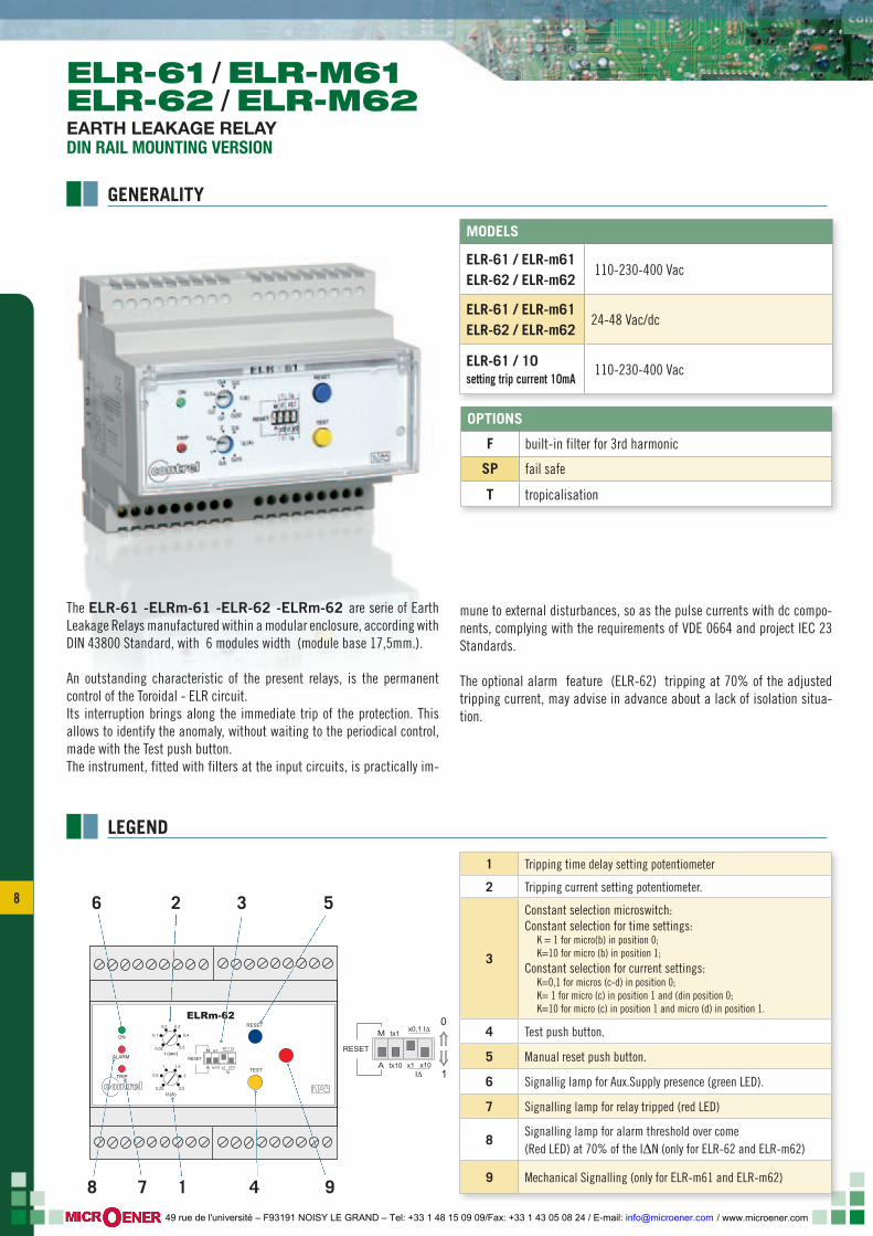
The ELR-61 -ELRm-61 -ELR-62 -ELRm-62 are serie of Earth Leakage Relays manufactured within a modular enclosure, according with DIN 43800 Standard, with 6 modules width (module base 17,5mm.).
An outstanding characteristic of the present relays, is the permanent control of the Toroidal - ELR circuit.Its interruption brings along the immediate trip of the protection. This allows to identify the anomaly, without waiting to the periodical control, made with the Test push button.The instrument, fitted with filters at the input circuits, is practically im-
mune to external disturbances, so as the pulse currents with dc compo-nents, complying with the requirements of VDE 0664 and project IEC 23 Standards.
The optional alarm feature (ELR-62) tripping at 70% of the adjusted tripping current, may advise in advance about a lack of isolation situa-tion.
LEGEND
OPTIONS
F built-in filter for 3rd harmonic
SP fail safe
T tropicalisation
MODELS
ELR-61 / ELR-m61 ELR-62 / ELR-m62
110-230-400 Vac
ELR-61 / ELR-m61 ELR-62 / ELR-m62
24-48 Vac/dc
ELR-61 / 10setting trip current 10mA
110-230-400 Vac
5
17 4 9
326
8
1 Tripping time delay setting potentiometer
2 Tripping current setting potentiometer.
3
Constant selection microswitch:Constant selection for time settings: K = 1 for micro(b) in position 0; K=10 for micro (b) in position 1; Constant selection for current settings: K=0,1 for micros (c-d) in position 0; K= 1 for micro (c) in position 1 and (din position 0; K=10 for micro (c) in position 1 and micro (d) in position 1.
4 Test push button.
5 Manual reset push button.
6 Signallig lamp for Aux.Supply presence (green LED).
7 Signalling lamp for relay tripped (red LED)
8Signalling lamp for alarm threshold over come(Red LED) at 70% of the I∆N (only for ELR-62 and ELR-m62)
9 Mechanical Signalling (only for ELR-m61 and ELR-m62)
ELR-61 / ELR-M61ELR-62 / ELR-M62EARTH LEAKAGE RELAYDIN RAIL MOUNTING VERSION
GENERALITY
/ www.microener.com 49 rue de l'université – F93191 NOISY LE GRAND – Tel: +33 1 48 15 09 09/Fax: +33 1 43 05 08 24 / E-mail: [email protected]
9 9123
4
4
6789
11
1413161718
10
N L1 L2 L3
Ba
*sspp
CT-1/...
15 2 1
TRIP ALARM
TEST
123
4
4
6789
11
1413161718
10
LOAD
N L1 L2 L3
Ba
*sspp
CT-1/...
15 2 1
TRIP TRIP
TEST
Aux Aux
SUPPLYEarth
LOAD
SUPPLYEarth
Remote Reset Remote Reset
123
4
4
6789
11
1413161718
10
N L1 L2 L3
Ba
*sspp
CT-1/...
15 2 1
TRIP ALARM
TEST
123
4
4
6789
11
1413161718
10
LOAD
N L1 L2 L3
Ba
*sspp
CT-1/...
15 2 1
TRIP TRIP
TEST
Aux Aux
SUPPLYEarth
LOAD
SUPPLYEarth
Remote Reset Remote Reset
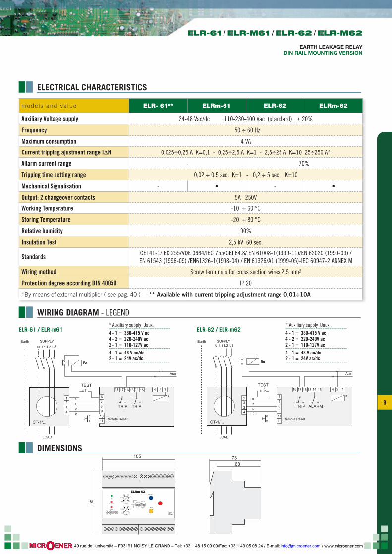
mode ls and va lue ELR- 61** ELRm-61 ELR-62 ELRm-62
Auxiliary Voltage supply 24-48 Vac/dc 110-230-400 Vac (standard) ± 20%
Frequency 50 ÷ 60 Hz
Maximum consumption 4 VA
Current tripping ajustment range I∆N 0,025÷0,25 A K=0,1 - 0,25÷2,5 A K=1 - 2,5÷25 A K=10 25÷250 A*
Allarm current range - 70%
Tripping time setting range 0,02 ÷ 0,5 sec. K=1 - 0,2 ÷ 5 sec. K=10
Mechanical Signalisation - • - •
Output: 2 changeover contacts 5A 250V
Working Temperature -10 + 60 °C
Storing Temperature -20 + 80 °C
Relative humidity 90%
Insulation Test 2,5 kV 60 sec.
Standards CEI 41-1/IEC 255/VDE 0664/IEC 755/CEI 64.8/ EN 61008-1(1999-11)/EN 62020 (1999-09) /EN 61543 (1996-09) /EN61326-1(1998-04) / EN 61326/A1 (1999-05)-IEC 60947-2 ANNEX M
Wiring method Screw terminals for cross section wires 2,5 mm2
Protection degree according DIN 40050 IP 20
*By means of external multiplier ( see pag. 40 ) - ** Available with current tripping adjustment range 0,01÷10A
105
90
7368
TEST
RESET
I (A)Δ
t (sec)
ON
TRIP
RESET
A
M
tx10
tx1
IΔx1 x10
x0,1 IΔ
ELRm-62
contrel 0,25
0,02
0,5
0,1
1
0,2
1,5
0,3
2
0,4
2,5
0,5
ALARM
* Auxiliary supply Uaux: -----------------------------------4 - 1 = 380-415 V ac4 - 2 = 220-240V ac2 - 1 = 110-127V ac-----------------------------------4 - 1 = 48 V ac/dc2 - 1 = 24V ac/dc-----------------------------------
* Auxiliary supply Uaux: -----------------------------------4 - 1 = 380-415 V ac4 - 2 = 220-240V ac2 - 1 = 110-127V ac-----------------------------------4 - 1 = 48 V ac/dc2 - 1 = 24V ac/dc-----------------------------------
ELR-61 / ELR-m61 ELR-62 / ELR-m62
ELECTRICAL CHARACTERISTICS
WIRING DIAGRAM - LEGEND
DIMENSIONS
ELR-61 / ELR-M61 / ELR-62 / ELR-M62
EARTH LEAKAGE RELAYDIN RAIL MOUNTING VERSION
/ www.microener.com 49 rue de l'université – F93191 NOISY LE GRAND – Tel: +33 1 48 15 09 09/Fax: +33 1 43 05 08 24 / E-mail: [email protected]
10
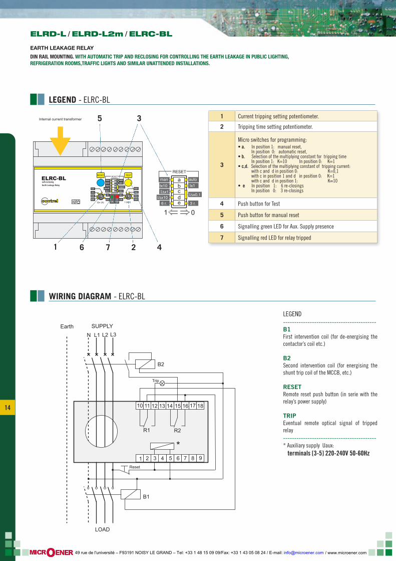
The ELRC-B, with all features and wide tripping current and time set-ting ranges of the ELR’s family, has been manufactured in a compact design of 6 modules DIN (17.5 mm) with a built-in Toroidal Transformer of 28 mm inner diameter for the passage of the cables.All this allows to reduce to the very minimum the wiring, the overall di-mensions and to avoid the disturbances, due to the possible electroma-gnetic fields which could be coupled to the wiring between the T/T and the ELR.
It also has a micro switch , which allows the selection of the working method of the end relay. This could be as normally de-energized (non tripped) or normally energized (fail safe).So as for the rest of the ELR’s range, the preset ELR is fitted with the appropriated filters at the input circuits to make it immune to external disturbances and the electronically control of the internal circuits and the T/T.
LEGEND
OPTIONS
F built-in filter for 3rd harmonic
T tropicalisation
1 Current tripping setting potentiometer.
2 Tripping time setting potentiometer.
3
Micro switches for programming:• a In position 1 automatic reset; In position 0 manual reset• b Selection of the multiplying constant Tripping time, in position 1 K=10 in position 0 K=1• c,d Selection of the multiplying constant of tripping current: With c d in position 0 K=0.1 With c in position 1, d in position 0 K=1 . With c, d in position 1 K=10• e In position 1 the output relays will be de-energised at rest, in position 0 the output relays will be energized at rest (fail safe).
4 Push button for Test
5 Push button for manual reset
6 Signalling green LED for Aux. Supply presence
7 Signalling red LED for relay tripped
MODELS
ELRC-B 110 Vac/dc - 230 - 400 Vac
ELRC-B 24-48 V ac/dc
TEST
RESET
I (A)Δ
t (sec)
ON
TRIP
RESET
A
M
tx10
tx1
IΔx1 x10
x0,1 IΔ
ELRC-B
contrel 0,25
0,02
0,5
0,1
1
0,2
1,5
0,3
2
0,4
2,5
0,5
ALARM
RESET
A
tx10
x1
x10
N
M
tx1
x0,1
F.S.
IΔ IΔ
ELRC-BEarth Leaakage Relay
Internal current transformer
1 0
3
27 4
5
1 6
ELRC-BEARTH LEAKAGE RELAY“COMPACT” VERSION WITH BUIT-IN TOROIDAL TRANSFORMER FOR DIN RAIL MOUNTING
GENERALITY
/ www.microener.com 49 rue de l'université – F93191 NOISY LE GRAND – Tel: +33 1 48 15 09 09/Fax: +33 1 43 05 08 24 / E-mail: [email protected]
11 11
1 2 3 4 5 6 7 8 9
11 12 13 14 15 16 17 1810
LOAD
N L1 L2 L3
Ba
Aux
*
SUPPLYEarth
mode ls and va lue ELRC-B
Auxiliary Voltage supply 24-48Vac/dc 110 - 230 - 400 Vac (standard)
Frequency 50 ÷ 60 Hz
Maximum consumption 3 VA
Current tripping ajustment range I∆N 0,025÷0,25A K=0,1 - 0,25÷2,5A K=1 - 2,5÷25A K=10
Tripping time setting range t 0,02 ÷ 0,5 sec. K=1 - 0,2 ÷ 5 sec. K=10
Built in toroidal transformer’s diammeter 28 mm
Output: 2 changeover contacts 5A 250V carico resistivo
Working Temperature -10 + 60°C
Storing Temperature -20 + 80°C
Relative humidity < 90%
Insulation Test 2,5 kV 60 sec.
Standards CEI 41-1/IEC 255/VDE 0664/IEC 755/CEI 64.8/ EN 61008-1(1999-11)/EN 62020 (1999-09) /EN 61543 (1996-09) /EN61326-1(1998-04) / EN 61326/A1 (1999-05)-IEC 60947-2 ANNEX M
Wiring method Terminals for cross section wires 2,5 mm2
Mounting DIN 50022 Snap on DIN rail 35 mm
Protection degree IP 40 front with closed cover - IP 20 enclosure
105
90
28
267368
TEST
RESET
I (A)Δ
t (sec)
ON
TRIP
RESET
A
M
tx10
tx1
IΔx1 x10
x0,1 IΔ
ELRC-B
contrel 0,25
0,02
0,5
0,1
1
0,2
1,5
0,3
2
0,4
2,5
0,5
ALARM
ELRC-BEarth Leaakage Relay
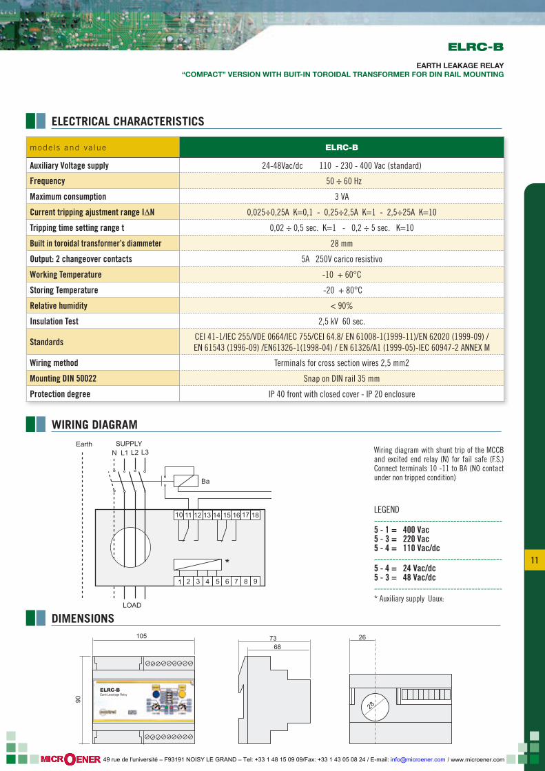
Wiring diagram with shunt trip of the MCCB and excited end relay (N) for fail safe (F.S.) Connect terminals 10 -11 to BA (NO contact under non tripped condition)
LEGEND------------------------------------------5 - 1 = 400 Vac5 - 3 = 220 Vac5 - 4 = 110 Vac/dc------------------------------------------5 - 4 = 24 Vac/dc5 - 3 = 48 Vac/dc------------------------------------------* Auxiliary supply Uaux:
ELECTRICAL CHARACTERISTICS
WIRING DIAGRAM
DIMENSIONS
ELRC-B
EARTH LEAKAGE RELAY“COMPACT” VERSION WITH BUIT-IN TOROIDAL TRANSFORMER FOR DIN RAIL MOUNTING
/ www.microener.com 49 rue de l'université – F93191 NOISY LE GRAND – Tel: +33 1 48 15 09 09/Fax: +33 1 43 05 08 24 / E-mail: [email protected]
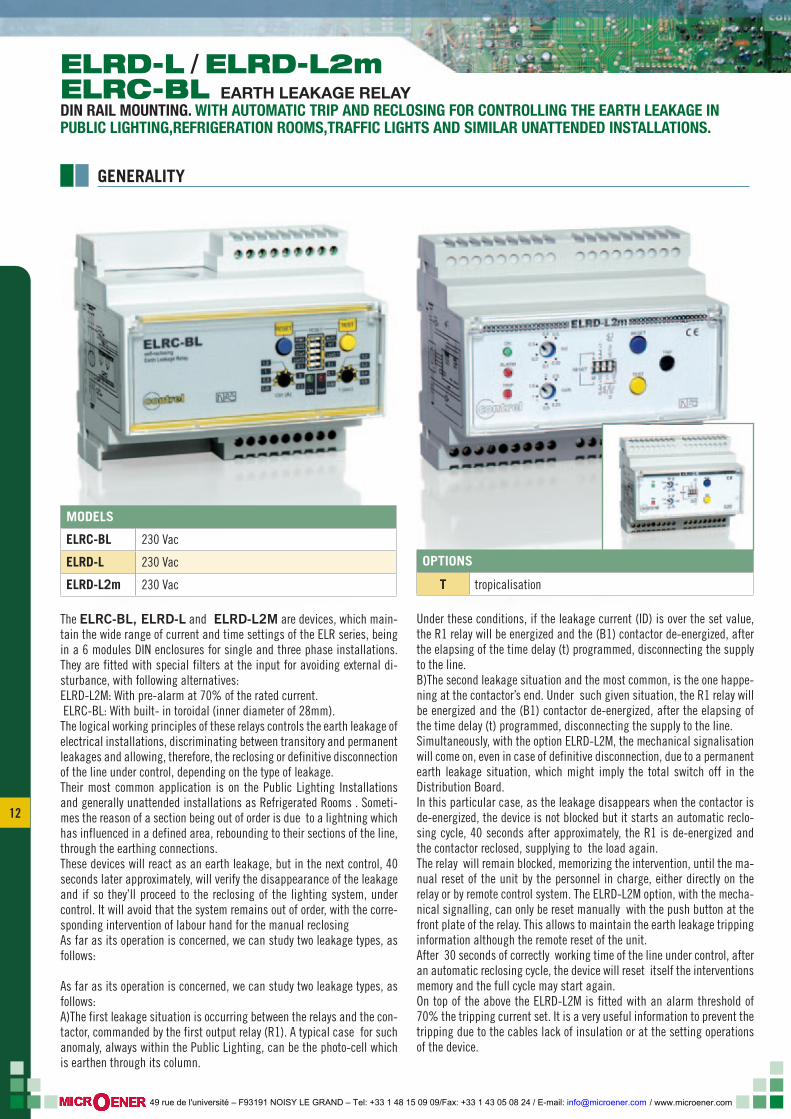
12
The ELRC-BL, ELRD-L and ELRD-L2M are devices, which main-tain the wide range of current and time settings of the ELR series, being in a 6 modules DIN enclosures for single and three phase installations. They are fitted with special filters at the input for avoiding external di-sturbance, with following alternatives:ELRD-L2M: With pre-alarm at 70% of the rated current. ELRC-BL: With built- in toroidal (inner diameter of 28mm).The logical working principles of these relays controls the earth leakage of electrical installations, discriminating between transitory and permanent leakages and allowing, therefore, the reclosing or definitive disconnection of the line under control, depending on the type of leakage.Their most common application is on the Public Lighting Installations and generally unattended installations as Refrigerated Rooms . Someti-mes the reason of a section being out of order is due to a lightning which has influenced in a defined area, rebounding to their sections of the line, through the earthing connections.These devices will react as an earth leakage, but in the next control, 40 seconds later approximately, will verify the disappearance of the leakage and if so they’ll proceed to the reclosing of the lighting system, under control. It will avoid that the system remains out of order, with the corre-sponding intervention of labour hand for the manual reclosingAs far as its operation is concerned, we can study two leakage types, as follows:
As far as its operation is concerned, we can study two leakage types, as follows:A)The first leakage situation is occurring between the relays and the con-tactor, commanded by the first output relay (R1). A typical case for such anomaly, always within the Public Lighting, can be the photo-cell which is earthen through its column.
Under these conditions, if the leakage current (ID) is over the set value, the R1 relay will be energized and the (B1) contactor de-energized, after the elapsing of the time delay (t) programmed, disconnecting the supply to the line.B)The second leakage situation and the most common, is the one happe-ning at the contactor’s end. Under such given situation, the R1 relay will be energized and the (B1) contactor de-energized, after the elapsing of the time delay (t) programmed, disconnecting the supply to the line.Simultaneously, with the option ELRD-L2M, the mechanical signalisation will come on, even in case of definitive disconnection, due to a permanent earth leakage situation, which might imply the total switch off in the Distribution Board.In this particular case, as the leakage disappears when the contactor is de-energized, the device is not blocked but it starts an automatic reclo-sing cycle, 40 seconds after approximately, the R1 is de-energized and the contactor reclosed, supplying to the load again. The relay will remain blocked, memorizing the intervention, until the ma-nual reset of the unit by the personnel in charge, either directly on the relay or by remote control system. The ELRD-L2M option, with the mecha-nical signalling, can only be reset manually with the push button at the front plate of the relay. This allows to maintain the earth leakage tripping information although the remote reset of the unit.After 30 seconds of correctly working time of the line under control, after an automatic reclosing cycle, the device will reset itself the interventions memory and the full cycle may start again. On top of the above the ELRD-L2M is fitted with an alarm threshold of 70% the tripping current set. It is a very useful information to prevent the tripping due to the cables lack of insulation or at the setting operations of the device.
ELRD-L / ELRD-L2mELRC-BL EARTH LEAKAGE RELAYDIN RAIL MOUNTING. WITH AUTOMATIC TRIP AND RECLOSING FOR CONTROLLING THE EARTH LEAKAGE IN PUBLIC LIGHTING,REFRIGERATION ROOMS,TRAFFIC LIGHTS AND SIMILAR UNATTENDED INSTALLATIONS.
OPTIONS
T tropicalisation
MODELS
ELRC-BL 230 Vac
ELRD-L 230 Vac
ELRD-L2m 230 Vac
GENERALITY
/ www.microener.com 49 rue de l'université – F93191 NOISY LE GRAND – Tel: +33 1 48 15 09 09/Fax: +33 1 43 05 08 24 / E-mail: [email protected]
13 13
105
28
267368
105
ΙΔx0,1
tx1
man
3 r.
IΔx1ΙΔx10
tx10
auto
6 r.
RESETRESET
ON TRIP
2
2,50,25
0,5
1
1,5
0,3
0,4
0,5
0,2
0,02
0,1
I n (A)Δ t (sec)
TEST
ELRC-BL
contrel
self-reclosingEarth Leakage Relay
2,5
TEST
RESET
RESET
I (A)Δ
t (sec)ON
TRIP
TRIPALARM
A
M
0,4+
tx10
0,4+
tx1
IΔx1 x10
x0,1
IΔ
contrel 0,25
0,02
0,5
0,1
1
0,2
1,5
0,3
2
0,4
2,5
0,5
ELRD-L2m
90
ELECTRICAL CHARACTERISTICS
DIMENSIONS
ELRD-L / ELRD-L2m / ELRC-BL
EARTH LEAKAGE RELAY
DIN RAIL MOUNTING. WITH AUTOMATIC TRIP AND RECLOSING FOR CONTROLLING THE EARTH LEAKAGE IN PUBLIC LIGHTING,REFRIGERATION ROOMS,TRAFFIC LIGHTS AND SIMILAR UNATTENDED INSTALLATIONS.
mode ls and va lue ELRC-BL ELRD-L ELRD-L2m
Auxiliary Voltage supply 230 Vac
Frequency 50 ÷ 60 Hz
Maximum consumption 4 VA
Setting range for current tripping I∆N 0,025÷0,25A K=0,1 - 0,25÷2,5A K=1 - 2,5÷25A K=10
Setting range for current alarm - - 70% I∆N
Setting range for time delay R1 0,02 ÷ 0,5 sec. K=1 - 0,2 ÷ 5 sec. K=10
Setting range for time delay R2 Delay for R1 + 0,4 sec.
Self-closing With micro switch in postion AUT
Number of self-closing attempts 3 or 6 consecutive max 3 consecutives
Time elapsed between self-closings 25÷35 sec. 50÷70 sec.
Memory reset 30 seconds after operating without any current leakage
Mechanical tripping signal - - It comes with the definitive blocking
Output relays R1 NO-C-NC contact 5A 250V resistive load - R2 NO contact 5A 250V resistive load
Hole’s diameter for passing the cables 28 mm -
Working Temperature -10 + 60°C
Storing Temperature -20 + 80°C
Relative humidity <90%
Insulation Test 2,5 kV 60 sec.
Standards CEI 41-1/IEC 255/VDE 0664/IEC 755/CEI 64.8/ EN 61008-1(1999-11)/EN 62020 (1999-09) /EN 61543 (1996-09) /EN61326-1(1998-04) / EN 61326/A1 (1999-05)-IEC 60947-2 ANNEX M
Wiring method By terminal block with cross section cable of 2,5 mm2
Mounting according with DIN 50022 Mounting on DIN rail 35 mm
Protection degree IP 40 front with closed cover - IP 20 enclosure
/ www.microener.com 49 rue de l'université – F93191 NOISY LE GRAND – Tel: +33 1 48 15 09 09/Fax: +33 1 43 05 08 24 / E-mail: [email protected]
14
LEGEND - ELRC-BL
1 Current tripping setting potentiometer.
2 Tripping time setting potentiometer.
3
Micro switches for programming:• a. In position 1: manual reset, In position 0: automatic reset,• b. Selection of the multiplying constant for tripping time In position 1: K=10 In position 0: K=1• c,d. Selection of the multiplying constant of tripping current: with c and d in position 0: K=0,1 with c in position 1 and d in position 0: K=1 with c and d in position 1: K=10• e In position 1: 6 re-closings In position 0: 3 re-closings
4 Push button for Test
5 Push button for manual reset
6 Signalling green LED for Aux. Supply presence
7 Signalling red LED for relay tripped
WIRING DIAGRAM - ELRC-BL
ELRD-L / ELRD-L2m / ELRC-BL
EARTH LEAKAGE RELAY
DIN RAIL MOUNTING. WITH AUTOMATIC TRIP AND RECLOSING FOR CONTROLLING THE EARTH LEAKAGE IN PUBLIC LIGHTING,REFRIGERATION ROOMS,TRAFFIC LIGHTS AND SIMILAR UNATTENDED INSTALLATIONS.
1 2 3 4 5 6 7 8 9
11 12 13 14 15 16 17 1810
B2
*
R1 R2
B1
Reset
Trip
LOAD
N L1 L2 L3
SUPPLYEarth
LEGEND------------------------------------------B1 First intervention coil (for de-energising the contactor’s coil etc.)
B2Second intervention coil (for energising the shunt trip coil of the MCCB, etc.)
RESETRemote reset push button (in serie with the relay’s power supply)
TRIPEventual remote optical signal of tripped relay------------------------------------------* Auxiliary supply Uaux: terminals [3-5] 220-240V 50-60Hz
ΙΔx0,1
tx1man
3 r.
IΔx1ΙΔx10
tx10auto
6 r.
RESET
abcde
ΙΔx0,1
tx1man
3 r.
IΔx1ΙΔx10
tx10auto
6 r.
RESETRESET
ON TRIP
2
2,50,25
0,5
1
1,5
0,3
0,4
0,5
0,2
0,02
0,1
I n (A)Δ t (sec)
TEST
ELRC-BL
contrel
self-reclosingEarth Leakage Relay
2,5
1 0
Internal current transformer 3
27 4
5
1 6
/ www.microener.com 49 rue de l'université – F93191 NOISY LE GRAND – Tel: +33 1 48 15 09 09/Fax: +33 1 43 05 08 24 / E-mail: [email protected]
15 15
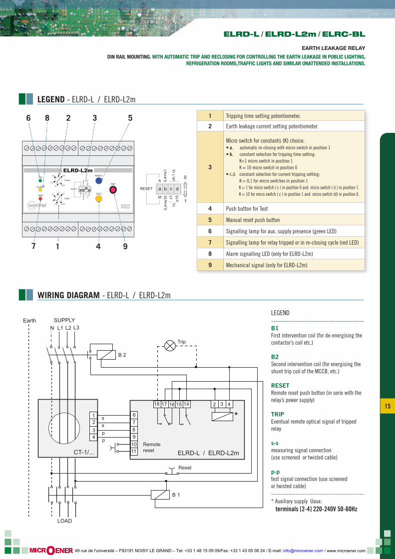
LEGEND - ELRD-L / ELRD-L2m
WIRING DIAGRAM - ELRD-L / ELRD-L2m
1 Tripping time setting potentiometer.
2 Earth leakage current setting potentiometer.
3
Micro switch for constants (K) choice:• a. automatic re-closing with micro switch in position 1• b. constant selection for tripping time setting: K=1 micro switch in position 1 K = 10 micro switch in position 0• c,d. constant selection for current tripping setting: K = 0,1 for micro switches in position 1 K = 1 for micro switch ( c ) in position 0 and micro switch ( d ) in position 1. K = 10 for micro switch ( c ) in position 1 and micro switch (d) in position 0.
4 Push button for Test
5 Manual reset push button
6 Signalling lamp for aux. supply presence (green LED)
7 Signalling lamp for relay tripped or in re-closing cycle (red LED)
8 Alarm signalling LED (only for ELRD-L2m)
9 Mechanical signal (only for ELRD-L2m)
ELRD-L / ELRD-L2m / ELRC-BL
EARTH LEAKAGE RELAY
DIN RAIL MOUNTING. WITH AUTOMATIC TRIP AND RECLOSING FOR CONTROLLING THE EARTH LEAKAGE IN PUBLIC LIGHTING,REFRIGERATION ROOMS,TRAFFIC LIGHTS AND SIMILAR UNATTENDED INSTALLATIONS.
LEGEND------------------------------------------B1 First intervention coil (for de-energising the contactor’s coil etc.)
B2Second intervention coil (for energising the shunt trip coil of the MCCB, etc.)
RESETRemote reset push button (in serie with the relay’s power supply)
TRIPEventual remote optical signal of tripped relay
s-smeasuring signal connection(use screened or twisted cable)
p-ptest signal connection (use screened or twisted cable) ------------------------------------------* Auxiliary supply Uaux: terminals [2-4] 220-240V 50-60Hz
1
2
2
3
3
4
4
6
7
89
11
1415161718
10
B 2
B 1
*
Reset
Trip
s
s
p
pRemoteresetCT-1/... ELRD-L / ELRD-L2m
N L1 L2 L3
LOAD
SUPPLYEarth
TEST
RESET
RESET
I (A)Δ
t (sec)ON
TRIP
TRIPALARM
A
M
0,4+
tx10
0,4+
tx1
IΔx1 x10
x0,1
IΔ
contrel 0,25
0,02
0,5
0,1
1
0,2
1,5
0,3
2
0,4
2,5
0,5
a b c d
ELRD-L2m
RESET
A
M
0,4+
tx10
0,4+
tx1
IΔx1 x10
x0,1
IΔ0
1
2 3 5
94
6 8
7 1
/ www.microener.com 49 rue de l'université – F93191 NOISY LE GRAND – Tel: +33 1 48 15 09 09/Fax: +33 1 43 05 08 24 / E-mail: [email protected]
16
1 0
abcd
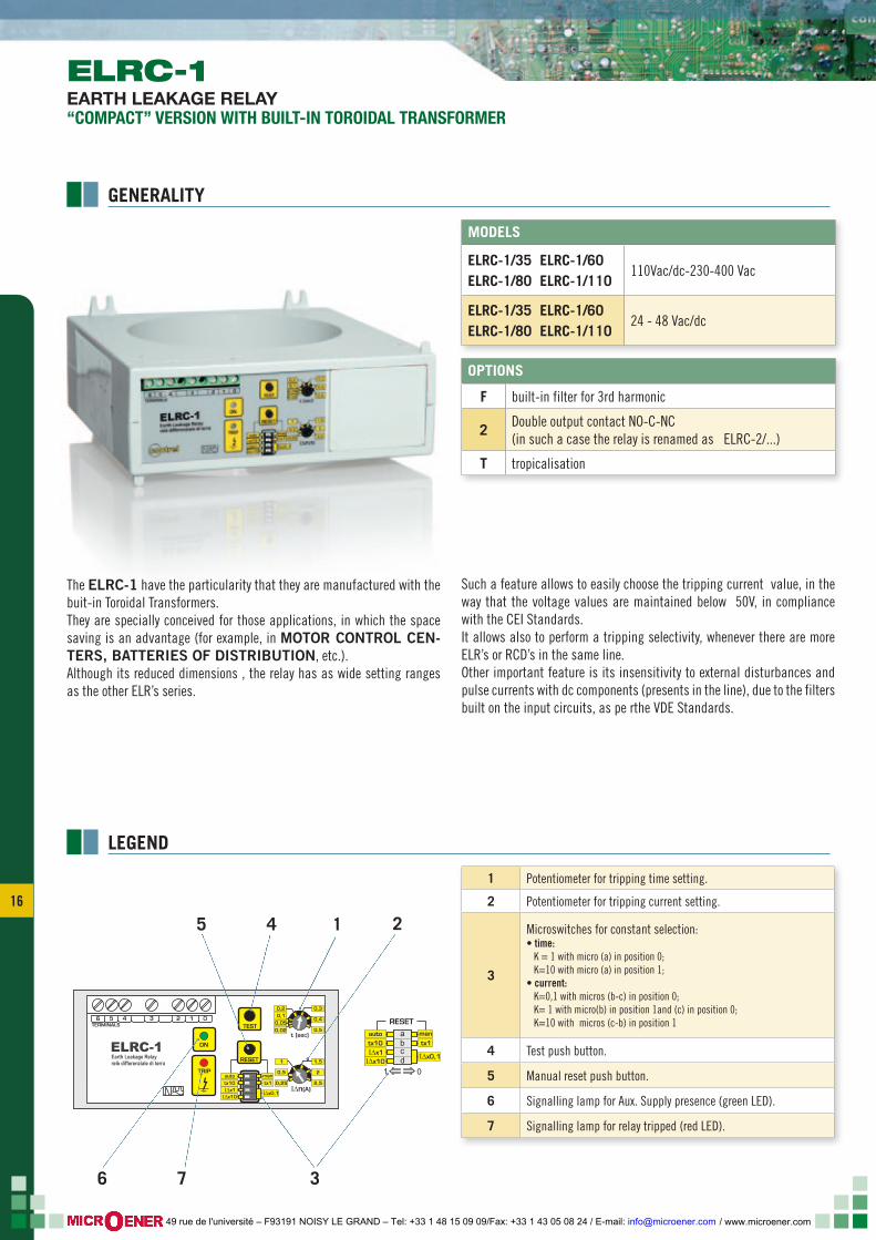
The ELRC-1 have the particularity that they are manufactured with the buit-in Toroidal Transformers.They are specially conceived for those applications, in which the space saving is an advantage (for example, in MOTOR CONTROL CEN-TERS, BATTERIES OF DISTRIBUTION, etc.). Although its reduced dimensions , the relay has as wide setting ranges as the other ELR’s series.
Such a feature allows to easily choose the tripping current value, in the way that the voltage values are maintained below 50V, in compliance with the CEI Standards.It allows also to perform a tripping selectivity, whenever there are more ELR’s or RCD’s in the same line.Other important feature is its insensitivity to external disturbances and pulse currents with dc components (presents in the line), due to the filters built on the input circuits, as pe rthe VDE Standards.
LEGEND
1 2
376
45
1 Potentiometer for tripping time setting.
2 Potentiometer for tripping current setting.
3
Microswitches for constant selection:• time: K = 1 with micro (a) in position 0; K=10 with micro (a) in position 1;• current: K=0,1 with micros (b-c) in position 0; K= 1 with micro(b) in position 1and (c) in position 0; K=10 with micros (c-b) in position 1
4 Test push button.
5 Manual reset push button.
6 Signalling lamp for Aux. Supply presence (green LED).
7 Signalling lamp for relay tripped (red LED).
OPTIONS
F built-in filter for 3rd harmonic
2 Double output contact NO-C-NC (in such a case the relay is renamed as ELRC-2/...)
T tropicalisation
MODELS
ELRC-1/35 ELRC-1/60 ELRC-1/80 ELRC-1/110
110Vac/dc-230-400 Vac
ELRC-1/35 ELRC-1/60 ELRC-1/80 ELRC-1/110
24 - 48 Vac/dc
ELRC-1EARTH LEAKAGE RELAY“COMPACT” VERSION WITH BUILT-IN TOROIDAL TRANSFORMER
GENERALITY
/ www.microener.com 49 rue de l'université – F93191 NOISY LE GRAND – Tel: +33 1 48 15 09 09/Fax: +33 1 43 05 08 24 / E-mail: [email protected]
17 17
mode ls and va lue ELRC-1
Auxiliary Voltage supply 24-48V ac/dc / 110 Vac/dc - 230 - 400 Vac ± 20% (standard)
Frequency 50 ÷ 60 Hz
Maximum consumption 3 VA
Current tripping ajustment range I∆N 0,025÷0,25A K=0,1 - 0,25÷2,5A K=1 - 2,5÷25A K=10
Tripping time setting range 0,02 ÷ 0,5 sec. K=1 - 0,2 ÷ 5 sec. K=10
Output: 2 change over contacts 5A 250V
Working Temperature -10 + 60°C
Storing Temperature -20 + 80°C
Relative Humidity 90%
Insulation Test 2,5 kV 60 sec.
Standards CEI 41-1/IEC 255/VDE 0664/IEC 755/CEI 64.8/ EN 61008-1(1999-11)/EN 62020 (1999-09) /EN 61543 (1996-09) /EN61326-1(1998-04) / EN 61326/A1 (1999-05)-IEC 60947-2 ANNEX M
Wiring method Screw terminals for cross section wire 2,5 mm2
Terminals protection according with DIN 40050 IP20
BGF
E
H
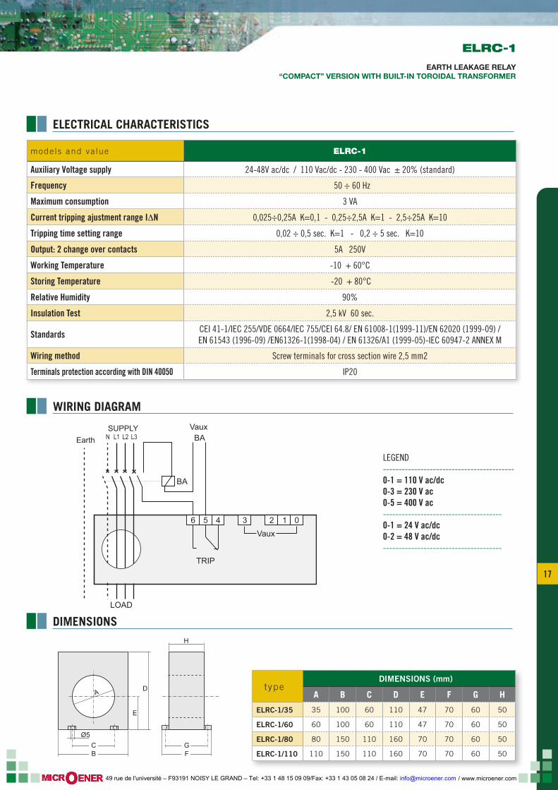
DA
CØ5
t ypeDIMENSIONS (mm)
A B C D E F G H
ELRC-1/35 35 100 60 110 47 70 60 50
ELRC-1/60 60 100 60 110 47 70 60 50
ELRC-1/80 80 150 110 160 70 70 60 50
ELRC-1/110 110 150 110 160 70 70 60 50
6 5 4 3 2 1
TRIP
LOAD
N L1 L2 L3
Vaux BA
BA
Vaux
0
SUPPLY
Earth
LEGEND------------------------------------------0-1 = 110 V ac/dc0-3 = 230 V ac0-5 = 400 V ac--------------------------------------0-1 = 24 V ac/dc0-2 = 48 V ac/dc--------------------------------------
ELECTRICAL CHARACTERISTICS
WIRING DIAGRAM
DIMENSIONS
ELRC-1
EARTH LEAKAGE RELAY“COMPACT” VERSION WITH BUILT-IN TOROIDAL TRANSFORMER
/ www.microener.com 49 rue de l'université – F93191 NOISY LE GRAND – Tel: +33 1 48 15 09 09/Fax: +33 1 43 05 08 24 / E-mail: [email protected]
18
ab
cd
e
RESET
tx10 tx1
IΔx1
x10
OFF
1
AUTO MAN
ON
0
x0,1 IΔ
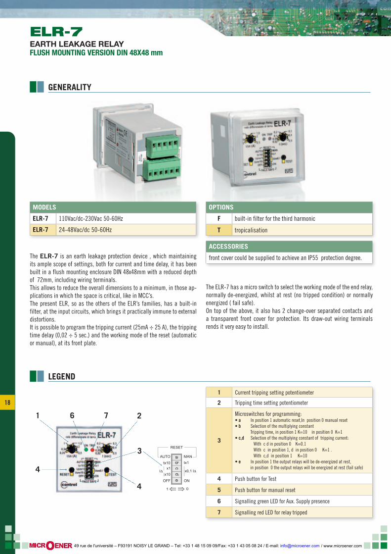
The ELR-7 is an earth leakage protection device , which maintaining its ample scope of settings, both for current and time delay, it has been built in a flush mounting enclosure DIN 48x48mm with a reduced depth of 72mm, including wiring terminals.This allows to reduce the overall dimensions to a minimum, in those ap-plications in which the space is critical, like in MCC’s.The present ELR, so as the others of the ELR’s families, has a built-in filter, at the input circuits, which brings it practically immune to external distortions.It is possible to program the tripping current (25mA ÷ 25 A), the tripping time delay (0,02 ÷ 5 sec.) and the working mode of the reset (automatic or manual), at its front plate.
The ELR-7 has a micro switch to select the working mode of the end relay, normally de-energized, whilst at rest (no tripped condition) or normally energized ( fail safe).On top of the above, it also has 2 change-over separated contacts and a transparent front cover for protection. Its draw-out wiring terminals rends it very easy to install.
4
2
4
1 6 7
3
1 Current tripping setting potentiometer
2 Tripping time setting potentiometer
3
Microswitches for programming:• a In position 1 automatic reset,In position 0 manual reset• b Selection of the multiplying constant Tripping time, in position 1 K=10 in position 0 K=1• c,d Selection of the multiplying constant of tripping current: With c d in position 0 K=0.1 With c in position 1, d in position 0 K=1 . With c,d in position 1 K=10• e In position 1 the output relays will be de-energized at rest, in position 0 the output relays will be energized at rest (fail safe)
4 Push button for Test
5 Push button for manual reset
6 Signalling green LED for Aux. Supply presence
7 Signalling red LED for relay tripped
OPTIONS
F built-in filter for the third harmonic
T tropicalisation
ACCESSORIES
front cover could be supplied to achieve an IP55 protection degree.
MODELS
ELR-7 110Vac/dc-230Vac 50-60Hz
ELR-7 24-48Vac/dc 50-60Hz
LEGEND
ELR-7EARTH LEAKAGE RELAYFLUSH MOUNTING VERSION DIN 48X48 mm
GENERALITY
/ www.microener.com 49 rue de l'université – F93191 NOISY LE GRAND – Tel: +33 1 48 15 09 09/Fax: +33 1 43 05 08 24 / E-mail: [email protected]
19 19
12345
7 8 10 11 129
LOAD
Ba
Aux
*
12
34
ELR-7
CT-1/...
x x x x
N L1 L2 L3SUPPLYEarth
45
45
r.3
4820 63 9
44 48
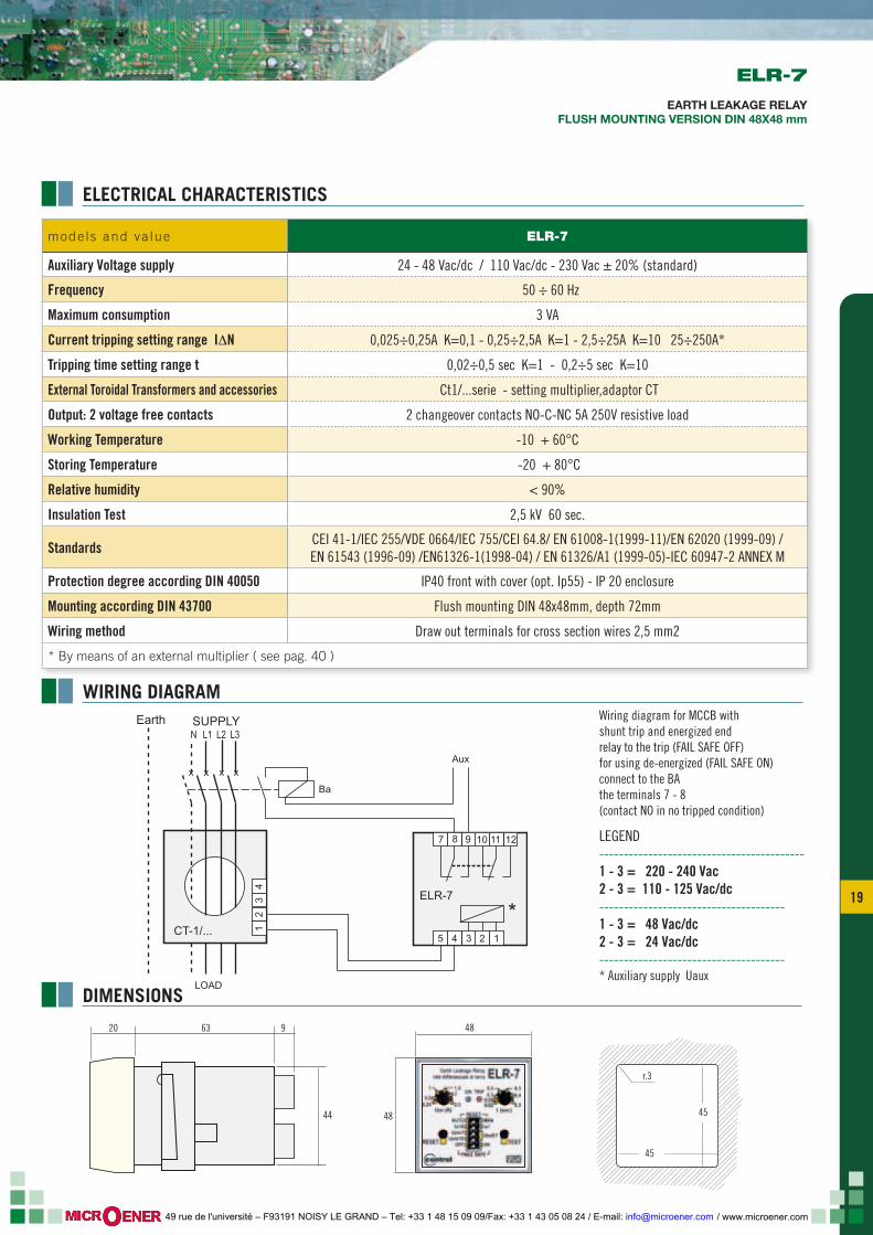
Wiring diagram for MCCB withshunt trip and energized endrelay to the trip (FAIL SAFE OFF)for using de-energized (FAIL SAFE ON) connect to the BAthe terminals 7 - 8 (contact NO in no tripped condition)
LEGEND------------------------------------------1 - 3 = 220 - 240 Vac2 - 3 = 110 - 125 Vac/dc--------------------------------------1 - 3 = 48 Vac/dc2 - 3 = 24 Vac/dc--------------------------------------* Auxiliary supply Uaux
ELR-7
EARTH LEAKAGE RELAYFLUSH MOUNTING VERSION DIN 48X48 mm
ELECTRICAL CHARACTERISTICS
WIRING DIAGRAM
DIMENSIONS
mode ls and va lue ELR-7
Auxiliary Voltage supply 24 - 48 Vac/dc / 110 Vac/dc - 230 Vac ± 20% (standard)
Frequency 50 ÷ 60 Hz
Maximum consumption 3 VA
Current tripping setting range I∆N 0,025÷0,25A K=0,1 - 0,25÷2,5A K=1 - 2,5÷25A K=10 25÷250A*
Tripping time setting range t 0,02÷0,5 sec K=1 - 0,2÷5 sec K=10
External Toroidal Transformers and accessories Ct1/...serie - setting multiplier,adaptor CT
Output: 2 voltage free contacts 2 changeover contacts NO-C-NC 5A 250V resistive load
Working Temperature -10 + 60°C
Storing Temperature -20 + 80°C
Relative humidity < 90%
Insulation Test 2,5 kV 60 sec.
Standards CEI 41-1/IEC 255/VDE 0664/IEC 755/CEI 64.8/ EN 61008-1(1999-11)/EN 62020 (1999-09) /EN 61543 (1996-09) /EN61326-1(1998-04) / EN 61326/A1 (1999-05)-IEC 60947-2 ANNEX M
Protection degree according DIN 40050 IP40 front with cover (opt. Ip55) - IP 20 enclosure
Mounting according DIN 43700 Flush mounting DIN 48x48mm, depth 72mm
Wiring method Draw out terminals for cross section wires 2,5 mm2
* By means of an external multiplier ( see pag. 40 )
/ www.microener.com 49 rue de l'université – F93191 NOISY LE GRAND – Tel: +33 1 48 15 09 09/Fax: +33 1 43 05 08 24 / E-mail: [email protected]
20
RESET
TEST
0,25 0,5 1
0,30,40,5
0,20,10,050,02
t (sec)
ON
TRIPMEMORY
contrelTRIP
I n (A)Δ
2 1,52,5
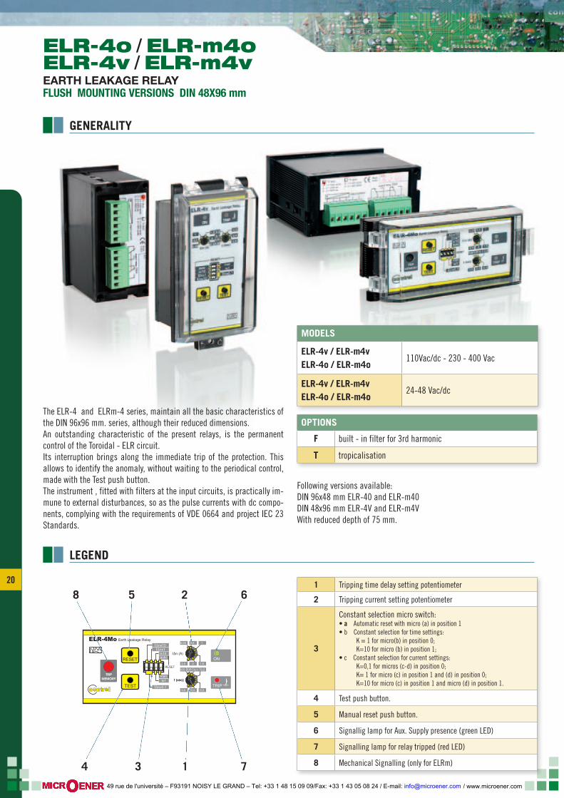
Earth Leakage RelayELR-4Mo
RESET
IΔnx0,1
tx1man
IΔnx1IΔnx10
tx10auto
The ELR-4 and ELRm-4 series, maintain all the basic characteristics of the DIN 96x96 mm. series, although their reduced dimensions.An outstanding characteristic of the present relays, is the permanent control of the Toroidal - ELR circuit.Its interruption brings along the immediate trip of the protection. This allows to identify the anomaly, without waiting to the periodical control, made with the Test push button.The instrument , fitted with filters at the input circuits, is practically im-mune to external disturbances, so as the pulse currents with dc compo-nents, complying with the requirements of VDE 0664 and project IEC 23 Standards.
Following versions available:DIN 96x48 mm ELR-40 and ELR-m40 DIN 48x96 mm ELR-4V and ELR-m4V With reduced depth of 75 mm.
LEGEND
2 6
714 3
581 Tripping time delay setting potentiometer
2 Tripping current setting potentiometer
3
Constant selection micro switch:• a Automatic reset with micro (a) in position 1 • b Constant selection for time settings: K = 1 for micro(b) in position 0; K=10 for micro (b) in position 1; • c Constant selection for current settings: K=0,1 for micros (c-d) in position 0; K= 1 for micro (c) in position 1 and (d) in position 0; K=10 for micro (c) in position 1 and micro (d) in position 1.
4 Test push button.
5 Manual reset push button.
6 Signallig lamp for Aux. Supply presence (green LED)
7 Signalling lamp for relay tripped (red LED)
8 Mechanical Signalling (only for ELRm)
OPTIONS
F built - in filter for 3rd harmonic
T tropicalisation
MODELS
ELR-4v / ELR-m4vELR-4o / ELR-m4o
110Vac/dc - 230 - 400 Vac
ELR-4v / ELR-m4vELR-4o / ELR-m4o
24-48 Vac/dc
ELR-4o / ELR-m4oELR-4v / ELR-m4vEARTH LEAKAGE RELAYFLUSH MOUNTING VERSIONS DIN 48X96 mm
GENERALITY
/ www.microener.com 49 rue de l'université – F93191 NOISY LE GRAND – Tel: +33 1 48 15 09 09/Fax: +33 1 43 05 08 24 / E-mail: [email protected]
21 21
55
48
96 123
45
45
r.3
91 x
44
75 31
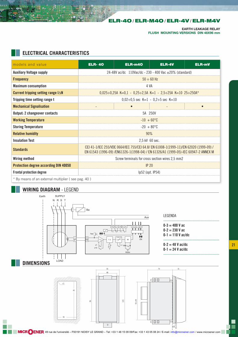
LOAD
Aux
N R S TSUPPLY
Ba
Earth
12
9
1112
8
M ON
Reset
x1 x10
x10M
Test
I ∆I ∆0,02÷0,5
7 6 5 4 3 2 1 0
mode ls and va lue ELR- 4O ELR-m4O ELR-4V ELR-mV
Auxiliary Voltage supply 24-48V ac/dc 110Vac/dc - 230 - 400 Vac ±20% (standard)
Frequency 50 ÷ 60 Hz
Maximum consumption 4 VA
Current tripping setting range I∆N 0,025÷0,25A K=0,1 - 0,25÷2,5A K=1 - 2,5÷25A K=10 25÷250A*
Tripping time setting range t 0,02÷0,5 sec K=1 - 0,2÷5 sec K=10
Mechanical Signalisation - • - •
Output: 2 changeover contacts 5A 250V
Working Temperature -10 + 60°C
Storing Temperature -20 + 80°C
Relative humidity 90%
Insulation Test 2,5 kV 60 sec.
Standards CEI 41-1/IEC 255/VDE 0664/IEC 755/CEI 64.8/ EN 61008-1(1999-11)/EN 62020 (1999-09) /EN 61543 (1996-09) /EN61326-1(1998-04) / EN 61326/A1 (1999-05)-IEC 60947-2 ANNEX M
Wiring method Screw terminals for cross section wires 2,5 mm2
Protection degree according DIN 40050 IP 20
Frontal protection degree Ip52 (opt. IP54)
* By means of an external multiplier ( see pag. 40 )
LEGENDA------------------------------------------0-3 = 400 V ac0-2 = 230 V ac0-1 = 110 V ac/dc------------------------------------------0-2 = 48 V ac/dc0-1 = 24 V ac/dc------------------------------------------
ELECTRICAL CHARACTERISTICS
WIRING DIAGRAM - LEGEND
DIMENSIONS
ELR-4O / ELR-M4O / ELR-4V / ELR-M4V
EARTH LEAKAGE RELAYFLUSH MOUNTING VERSIONS DIN 48X96 mm
/ www.microener.com 49 rue de l'université – F93191 NOISY LE GRAND – Tel: +33 1 48 15 09 09/Fax: +33 1 43 05 08 24 / E-mail: [email protected]
22
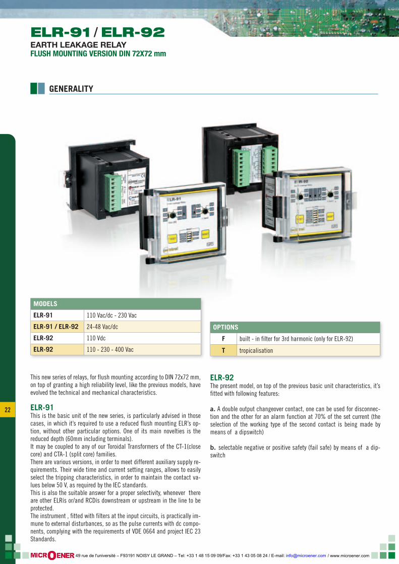
OPTIONS
F built - in filter for 3rd harmonic (only for ELR-92)
T tropicalisation
MODELS
ELR-91 110 Vac/dc - 230 Vac
ELR-91 / ELR-92 24-48 Vac/dc
ELR-92 110 Vdc
ELR-92 110 - 230 - 400 Vac
This new series of relays, for flush mounting according to DIN 72x72 mm, on top of granting a high reliability level, like the previous models, have evolved the technical and mechanical characteristics.
ELR-91This is the basic unit of the new series, is particularly advised in those cases, in which it’s required to use a reduced flush mounting ELR’s op-tion, without other particular options. One of its main novelties is the reduced depth (60mm including terminals). It may be coupled to any of our Toroidal Transformers of the CT-1(close core) and CTA-1 (split core) families. There are various versions, in order to meet different auxiliary supply re-quirements. Their wide time and current setting ranges, allows to easily select the tripping characteristics, in order to maintain the contact va-lues below 50 V, as required by the IEC standards.This is also the suitable answer for a proper selectivity, whenever there are other ELRís or/and RCDís downstream or upstream in the line to be protected.The instrument , fitted with filters at the input circuits, is practically im-mune to external disturbances, so as the pulse currents with dc compo-nents, complying with the requirements of VDE 0664 and project IEC 23 Standards.
ELR-92The present model, on top of the previous basic unit characteristics, it’s fitted with following features:
a. A double output changeover contact, one can be used for disconnec-tion and the other for an alarm function at 70% of the set current (the selection of the working type of the second contact is being made by means of a dipswitch)
b. selectable negative or positive safety (fail safe) by means of a dip-switch
ELR-91 / ELR-92EARTH LEAKAGE RELAYFLUSH MOUNTING VERSION DIN 72X72 mm
GENERALITY
/ www.microener.com 49 rue de l'université – F93191 NOISY LE GRAND – Tel: +33 1 48 15 09 09/Fax: +33 1 43 05 08 24 / E-mail: [email protected]
23 23
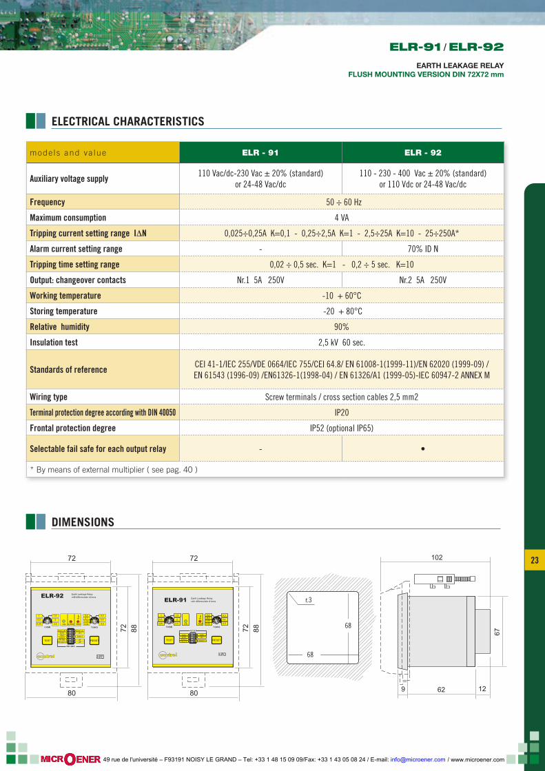
mode ls and va lue ELR - 91 ELR - 92
Auxiliary voltage supply 110 Vac/dc-230 Vac ± 20% (standard)or 24-48 Vac/dc
110 - 230 - 400 Vac ± 20% (standard)or 110 Vdc or 24-48 Vac/dc
Frequency 50 ÷ 60 Hz
Maximum consumption 4 VA
Tripping current setting range I∆N 0,025÷0,25A K=0,1 - 0,25÷2,5A K=1 - 2,5÷25A K=10 - 25÷250A*
Alarm current setting range - 70% ID N
Tripping time setting range 0,02 ÷ 0,5 sec. K=1 - 0,2 ÷ 5 sec. K=10
Output: changeover contacts Nr.1 5A 250V Nr.2 5A 250V
Working temperature -10 + 60°C
Storing temperature -20 + 80°C
Relative humidity 90%
Insulation test 2,5 kV 60 sec.
Standards of reference CEI 41-1/IEC 255/VDE 0664/IEC 755/CEI 64.8/ EN 61008-1(1999-11)/EN 62020 (1999-09) /EN 61543 (1996-09) /EN61326-1(1998-04) / EN 61326/A1 (1999-05)-IEC 60947-2 ANNEX M
Wiring type Screw terminals / cross section cables 2,5 mm2
Terminal protection degree according with DIN 40050 IP20
Frontal protection degree IP52 (optional IP65)
Selectable fail safe for each output relay - •
* By means of external multiplier ( see pag. 40 )
68
68
r.3
72
72
80
88
62 129
102
67
TCS-3 TCS-4
ΙΔn(A) t (sec)
TEST RESET
1
0,5
IΔnx0,1
tx1man
IΔnx1IΔnx10
tx10auto
ON TRIP
RESET
1,5
2
2,5
0,3
0,4
0,5
0,10,050,02
0,2
Earth Leakage Relayrelè differenziale di terraELR-91
contrel
0,25
72
72
80
88ΙΔn(A) t (sec)
TEST RESET
1
0,25
0,5
ΙΔx0,1
tx1alarm on
FS tripFS alarm
IΔx1ΙΔx10
tx10alarm off
ON TRIP
1,5
2
2,5
0,3
0,4
0,5
0,10,050,02
0,2
ALARM
offoff
FAIL SAFE
ELR-92 Earth Leakage RelayrelË differenziale di terra
contrel
ELECTRICAL CHARACTERISTICS
DIMENSIONS
ELR-91 / ELR-92
EARTH LEAKAGE RELAYFLUSH MOUNTING VERSION DIN 72X72 mm
/ www.microener.com 49 rue de l'université – F93191 NOISY LE GRAND – Tel: +33 1 48 15 09 09/Fax: +33 1 43 05 08 24 / E-mail: [email protected]
24
ΙΔn(A) t (sec)
TEST RESET
1
0,5
IΔnx0,1
tx1man
IΔnx1IΔnx10
tx10auto
ON TRIP
RESET
1,5
2
2,5
0,3
0,4
0,5
0,10,050,02
0,2
Earth Leakage Relayrelè differenziale di terraELR-91
contrel
0,25
ΙΔn(A) t (sec)
TEST RESET
1
0,25
0,5
ΙΔx0,1
tx1alarm on
FS tripFS alarm
IΔx1ΙΔx10
tx10alarm off
ON TRIP
1,5
2
2,5
0,3
0,4
0,5
0,10,050,02
0,2
ALARM
offoff
FAIL SAFE
ELR-92 Earth Leakage RelayrelË differenziale di terra
contrel
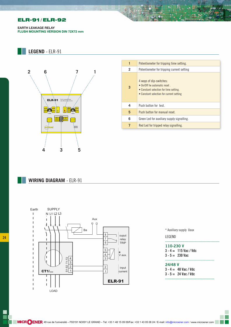
LEGEND - ELR-91
1
534
762
1 Potentiometer for tripping time setting.
2 Potentiometer for tripping current setting
3
4 ways of dip-switches:• On/Off he automatic reset .• Constant selection for time setting.• Constant selection for current setting
4 Push button for test.
5 Push button for manual reset.
6 Green Led for auxiliary supply signalling.
7 Red Led for tripped relay signalling.
12
3
5
6
LOAD
Ba
Aux
1234
ELR-91
CT1/...
x x x x
S1-
S2
T1-T
2
4
78 ouput
relayTRIP
*V aux.
inputcurrent
N L1 L2 L3SUPPLYEarth
* Auxiliary supply Uaux
LEGEND------------------------------------------110-230 V3 - 4 = 115 Vac / Vdc3 - 5 = 230 Vac--------------------------------------24/48 V3 - 4 = 48 Vac / Vdc3 - 5 = 24 Vac / Vdc--------------------------------------
WIRING DIAGRAM - ELR-91
ELR-91 / ELR-92
EARTH LEAKAGE RELAYFLUSH MOUNTING VERSION DIN 72X72 mm
/ www.microener.com 49 rue de l'université – F93191 NOISY LE GRAND – Tel: +33 1 48 15 09 09/Fax: +33 1 43 05 08 24 / E-mail: [email protected]
25 25
ΙΔn(A) t (sec)
TEST RESET
1
0,5
IΔnx0,1
tx1man
IΔnx1IΔnx10
tx10auto
ON TRIP
RESET
1,5
2
2,5
0,3
0,4
0,5
0,10,050,02
0,2
Earth Leakage Relayrelè differenziale di terraELR-91
contrel
0,25
ΙΔn(A) t (sec)
TEST RESET
1
0,25
0,5
ΙΔx0,1
tx1alarm on
FS tripFS alarm
IΔx1ΙΔx10
tx10alarm off
ON TRIP
1,5
2
2,5
0,3
0,4
0,5
0,10,050,02
0,2
ALARM
offoff
FAIL SAFE
ELR-92 Earth Leakage RelayrelË differenziale di terra
contrel
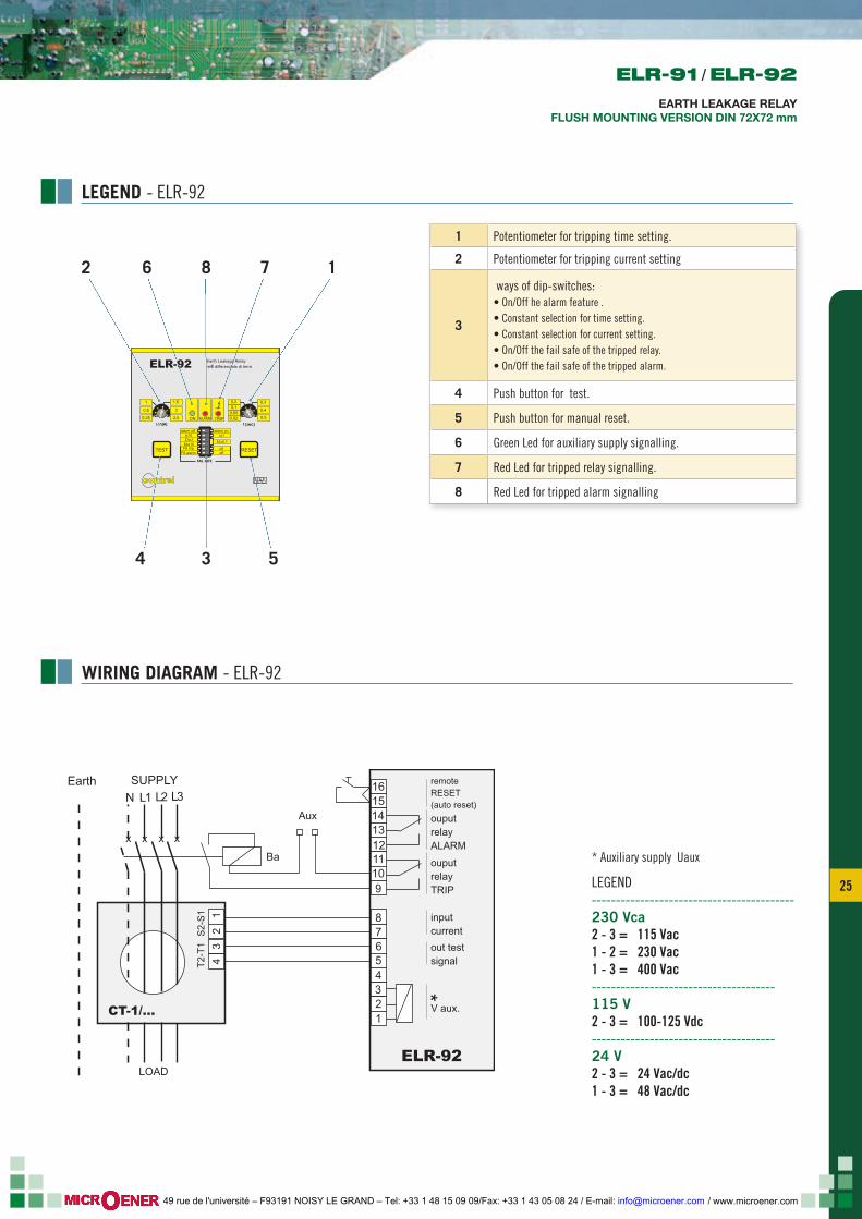
LEGEND - ELR-92
1 Potentiometer for tripping time setting.
2 Potentiometer for tripping current setting
3
ways of dip-switches:• On/Off he alarm feature .• Constant selection for time setting.• Constant selection for current setting.• On/Off the fail safe of the tripped relay.• On/Off the fail safe of the tripped alarm.
4 Push button for test.
5 Push button for manual reset.
6 Green Led for auxiliary supply signalling.
7 Red Led for tripped relay signalling.
8 Red Led for tripped alarm signalling
LOAD
Ba
Aux
12
34
CT-1/...
x x x x
S2-
S1
T2-T
1
ouputrelayTRIP
*V aux.
inputcurrentout testsignal
ouputrelayALARM
remoteRESET(auto reset)
ELR-92
12345678
910111213141516
12
N L1 L2 L3SUPPLYEarth
1
534
7862
* Auxiliary supply Uaux
LEGEND------------------------------------------230 Vca2 - 3 = 115 Vac1 - 2 = 230 Vac1 - 3 = 400 Vac--------------------------------------115 V2 - 3 = 100-125 Vdc--------------------------------------24 V2 - 3 = 24 Vac/dc1 - 3 = 48 Vac/dc
WIRING DIAGRAM - ELR-92
ELR-91 / ELR-92
EARTH LEAKAGE RELAYFLUSH MOUNTING VERSION DIN 72X72 mm
/ www.microener.com 49 rue de l'université – F93191 NOISY LE GRAND – Tel: +33 1 48 15 09 09/Fax: +33 1 43 05 08 24 / E-mail: [email protected]
26
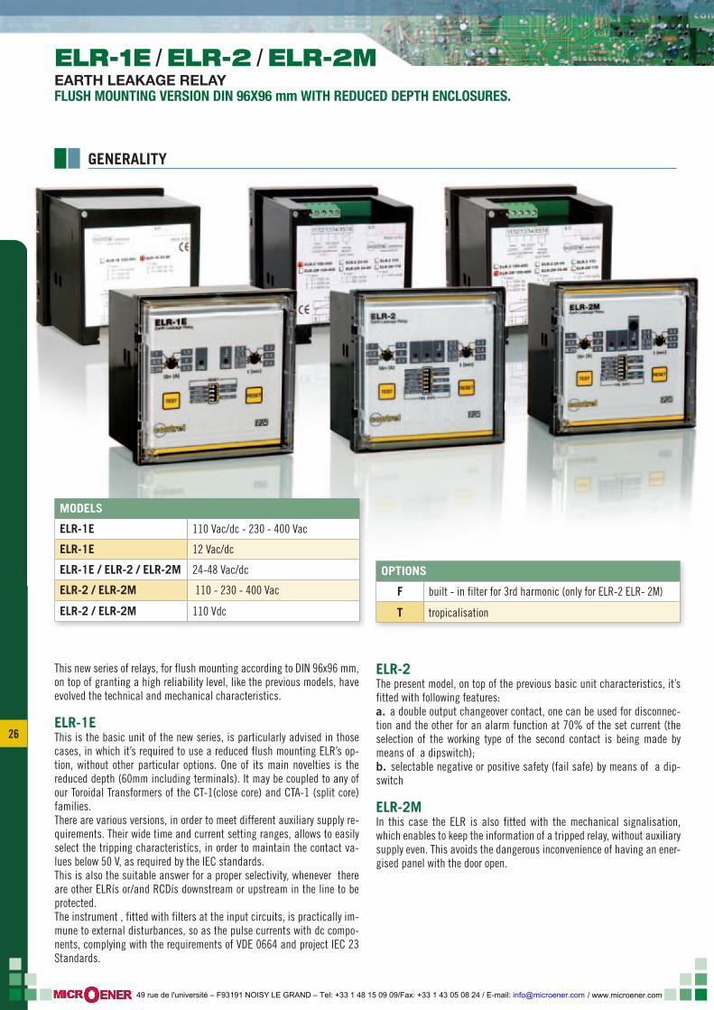
MODELS
ELR-1E 110 Vac/dc - 230 - 400 Vac
ELR-1E 12 Vac/dc
ELR-1E / ELR-2 / ELR-2M 24-48 Vac/dc
ELR-2 / ELR-2M 110 - 230 - 400 Vac
ELR-2 / ELR-2M 110 Vdc
This new series of relays, for flush mounting according to DIN 96x96 mm, on top of granting a high reliability level, like the previous models, have evolved the technical and mechanical characteristics.
ELR-1EThis is the basic unit of the new series, is particularly advised in those cases, in which it’s required to use a reduced flush mounting ELR’s op-tion, without other particular options. One of its main novelties is the reduced depth (60mm including terminals). It may be coupled to any of our Toroidal Transformers of the CT-1(close core) and CTA-1 (split core) families. There are various versions, in order to meet different auxiliary supply re-quirements. Their wide time and current setting ranges, allows to easily select the tripping characteristics, in order to maintain the contact va-lues below 50 V, as required by the IEC standards.This is also the suitable answer for a proper selectivity, whenever there are other ELRís or/and RCDís downstream or upstream in the line to be protected.The instrument , fitted with filters at the input circuits, is practically im-mune to external disturbances, so as the pulse currents with dc compo-nents, complying with the requirements of VDE 0664 and project IEC 23 Standards.
ELR-2The present model, on top of the previous basic unit characteristics, it’s fitted with following features:a. a double output changeover contact, one can be used for disconnec-tion and the other for an alarm function at 70% of the set current (the selection of the working type of the second contact is being made by means of a dipswitch);b. selectable negative or positive safety (fail safe) by means of a dip-switch
ELR-2MIn this case the ELR is also fitted with the mechanical signalisation, which enables to keep the information of a tripped relay, without auxiliary supply even. This avoids the dangerous inconvenience of having an ener-gised panel with the door open.
OPTIONS
F built - in filter for 3rd harmonic (only for ELR-2 ELR- 2M)
T tropicalisation
ELR-1E / ELR-2 / ELR-2MEARTH LEAKAGE RELAYFLUSH MOUNTING VERSION DIN 96X96 mm WITH REDUCED DEPTH ENCLOSURES.
GENERALITY
/ www.microener.com 49 rue de l'université – F93191 NOISY LE GRAND – Tel: +33 1 48 15 09 09/Fax: +33 1 43 05 08 24 / E-mail: [email protected]
27 27
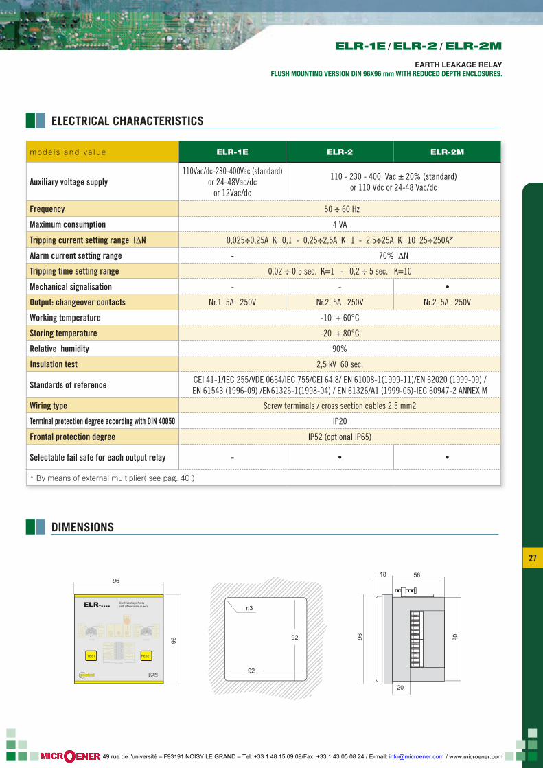
mode ls and va lue ELR-1E ELR-2 ELR-2M
Auxiliary voltage supply110Vac/dc-230-400Vac (standard)
or 24-48Vac/dcor 12Vac/dc
110 - 230 - 400 Vac ± 20% (standard) or 110 Vdc or 24-48 Vac/dc
Frequency 50 ÷ 60 Hz
Maximum consumption 4 VA
Tripping current setting range I∆N 0,025÷0,25A K=0,1 - 0,25÷2,5A K=1 - 2,5÷25A K=10 25÷250A*
Alarm current setting range - 70% I∆N
Tripping time setting range 0,02 ÷ 0,5 sec. K=1 - 0,2 ÷ 5 sec. K=10
Mechanical signalisation - - •
Output: changeover contacts Nr.1 5A 250V Nr.2 5A 250V Nr.2 5A 250V
Working temperature -10 + 60°C
Storing temperature -20 + 80°C
Relative humidity 90%
Insulation test 2,5 kV 60 sec.
Standards of reference CEI 41-1/IEC 255/VDE 0664/IEC 755/CEI 64.8/ EN 61008-1(1999-11)/EN 62020 (1999-09) /EN 61543 (1996-09) /EN61326-1(1998-04) / EN 61326/A1 (1999-05)-IEC 60947-2 ANNEX M
Wiring type Screw terminals / cross section cables 2,5 mm2
Terminal protection degree according with DIN 40050 IP20
Frontal protection degree IP52 (optional IP65)
Selectable fail safe for each output relay - • •
* By means of external multiplier( see pag. 40 )
96
96 9096
5618
20
92
92
r.3
ΙΔn(A) t (sec)
TEST RESET
1
0,25
0,5
ΙΔx0,1
tx1alarm on
FS tripFS alarm
IΔx1ΙΔx10
tx10alarm off
ON TRIP
1,51
2
2,5
0,30
0,4
0,5
0,10,050,02
0,2
ALARM
off
FAIL SAFE
MEM.
ELR-.... Earth Leakage RelayrelË differenziale di terra
off
contrel
ELECTRICAL CHARACTERISTICS
DIMENSIONS
ELR-1E / ELR-2 / ELR-2M
EARTH LEAKAGE RELAYFLUSH MOUNTING VERSION DIN 96X96 mm WITH REDUCED DEPTH ENCLOSURES.
/ www.microener.com 49 rue de l'université – F93191 NOISY LE GRAND – Tel: +33 1 48 15 09 09/Fax: +33 1 43 05 08 24 / E-mail: [email protected]
28
ΙΔn(A) t (sec)
TEST RESET
1
0,5
IΔnx0,1
tx1man
IΔnx1IΔnx10
tx10auto
ON TRIP
RESET
1,5
2
2,5
0,3
0,4
0,5
0,10,050,02
0,2
Earth Leakage Relayrelè differenziale di terraELR-1E
0,25
ΙΔn(A) t (sec)
TEST RESET
1
0,25
0,5
ΙΔx0,1
tx1alarm on
FS tripFS alarm
IΔx1ΙΔx10
tx10alarm off
ON TRIP
1,5
2
2,5
0,3
0,4
0,5
0,10,050,02
0,2
ALARM
off
FAIL SAFE
MEM.
ELR-2M Earth Leakage Relayrelè differenziale di terra
off
contrel
contrel
TESTTEST
TESTTEST
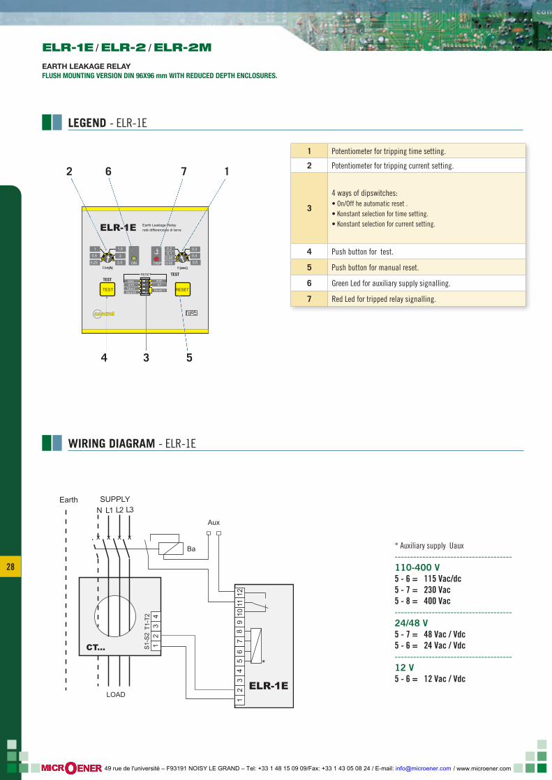
LEGEND - ELR-1E
1 Potentiometer for tripping time setting.
2 Potentiometer for tripping current setting.
3
4 ways of dipswitches:• On/Off he automatic reset .• Konstant selection for time setting.• Konstant selection for current setting.
4 Push button for test.
5 Push button for manual reset.
6 Green Led for auxiliary supply signalling.
7 Red Led for tripped relay signalling.
N L1 L2 L3SUPPLYEarth
12
34
57
810
1112
9
LOAD
Ba
Aux
*
12
34
ELR-1E
CT...
x x x x
S1-
S2
T1-T
2
6
1
534
762
* Auxiliary supply Uaux--------------------------------------110-400 V5 - 6 = 115 Vac/dc5 - 7 = 230 Vac5 - 8 = 400 Vac--------------------------------------24/48 V5 - 7 = 48 Vac / Vdc5 - 6 = 24 Vac / Vdc--------------------------------------12 V5 - 6 = 12 Vac / Vdc
WIRING DIAGRAM - ELR-1E
ELR-1E / ELR-2 / ELR-2M
EARTH LEAKAGE RELAYFLUSH MOUNTING VERSION DIN 96X96 mm WITH REDUCED DEPTH ENCLOSURES.
/ www.microener.com 49 rue de l'université – F93191 NOISY LE GRAND – Tel: +33 1 48 15 09 09/Fax: +33 1 43 05 08 24 / E-mail: [email protected]
29 29
ΙΔn(A) t (sec)
TEST RESET
1
0,5
IΔnx0,1
tx1man
IΔnx1IΔnx10
tx10auto
ON TRIP
RESET
1,5
2
2,5
0,3
0,4
0,5
0,10,050,02
0,2
Earth Leakage Relayrelè differenziale di terraELR-1E
0,25
ΙΔn(A) t (sec)
TEST RESET
1
0,25
0,5
ΙΔx0,1
tx1alarm on
FS tripFS alarm
IΔx1ΙΔx10
tx10alarm off
ON TRIP
1,5
2
2,5
0,3
0,4
0,5
0,10,050,02
0,2
ALARM
off
FAIL SAFE
MEM.
ELR-2M Earth Leakage Relayrelè differenziale di terra
off
contrel
contrel
TESTTEST
TESTTEST
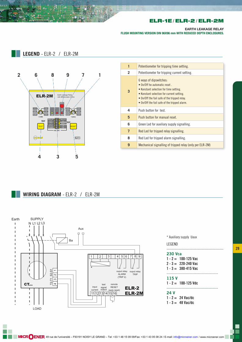
LEGEND - ELR-2 / ELR-2M
1 Potentiometer for tripping time setting.
2 Potentiometer for tripping current setting.
3
6 ways of dipswitches:• On/Off he automatic reset .• Konstant selection for time setting.• Konstant selection for current setting.• On/Off the fail safe of the tripped relay.• On/Off the fail safe of the tripped alarm.
4 Push button for test.
5 Push button for manual reset.
6 Green Led for auxiliary supply signalling.
7 Red Led for tripped relay signalling.
8 Red Led for tripped alarm signalling.
9 Mechanical signalling of tripped relay (only per ELR-2M)
1 2 3 4 5 7 8 9
LOAD
Ba
Aux
*
34
ELR-2ELR-2M
CT...
x x x x
S2-
S1
T2-T
1
6
11 12 1413 15 16
remoteRESET
(auto reset)input
current
testsignaloutput
ouput relayTRIP
ouput relayALARM(TRIP 2)
N L1 L2 L3SUPPLYEarth
12
1
534
78 962
* Auxiliary supply Uaux
LEGEND------------------------------------------230 Vca1 - 2 = 100-125 Vac2 - 3 = 220-240 Vac1 - 3 = 380-415 Vac--------------------------------------115 V1 - 2 = 100-125 Vdc--------------------------------------24 V1 - 2 = 24 Vac/dc1 - 3 = 48 Vac/dc
WIRING DIAGRAM - ELR-2 / ELR-2M
ELR-1E / ELR-2 / ELR-2M
EARTH LEAKAGE RELAYFLUSH MOUNTING VERSION DIN 96X96 mm WITH REDUCED DEPTH ENCLOSURES.
/ www.microener.com 49 rue de l'université – F93191 NOISY LE GRAND – Tel: +33 1 48 15 09 09/Fax: +33 1 43 05 08 24 / E-mail: [email protected]
30
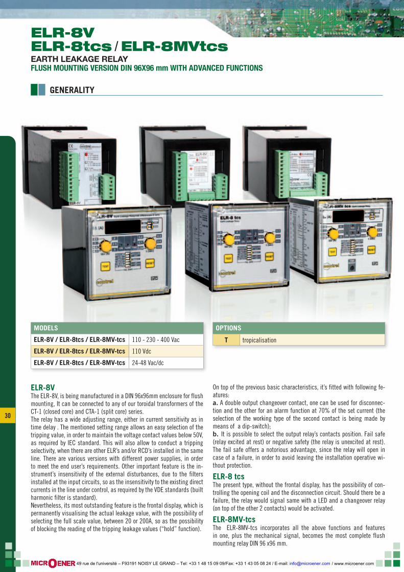
MODELS
ELR-8V / ELR-8tcs / ELR-8MV-tcs 110 - 230 - 400 Vac
ELR-8V / ELR-8tcs / ELR-8MV-tcs 110 Vdc
ELR-8V / ELR-8tcs / ELR-8MV-tcs 24-48 Vac/dc
ELR-8VThe ELR-8V, is being manufactured in a DIN 96x96mm enclosure for flush mounting, It can be connected to any of our toroidal transformers of the CT-1 (closed core) and CTA-1 (split core) series.The relay has a wide adjusting range, either in current sensitivity as in time delay . The mentioned setting range allows an easy selection of the tripping value, in order to maintain the voltage contact values below 50V, as required by IEC standard. This will also allow to conduct a tripping selectivity, when there are other ELR’s and/or RCD’s installed in the same line. There are various versions with different power supplies, in order to meet the end user’s requirements. Other important feature is the in-strument’s insensitivity of the external disturbances, due to the filters installed at the input circuits, so as the insensitivity to the existing direct currents in the line under control, as required by the VDE standards (built harmonic filter is standard).Nevertheless, its most outstanding feature is the frontal display, which is permanently visualising the actual leakage value, with the possibility of selecting the full scale value, between 20 or 200A, so as the possibility of blocking the reading of the tripping leakage values (“hold” function).
On top of the previous basic characteristics, it’s fitted with following fe-atures:a. A double output changeover contact, one can be used for disconnec-tion and the other for an alarm function at 70% of the set current (the selection of the working type of the second contact is being made by means of a dip-switch); b. It is possible to select the output relay’s contacts position. Fail safe (relay excited at rest) or negative safety (the relay is unexcited at rest). The fail safe offers a notorious advantage, since the relay will open in case of a failure, in order to avoid leaving the installation operative wi-thout protection.
ELR-8 tcsThe present type, without the frontal display, has the possibility of con-trolling the opening coil and the disconnection circuit. Should there be a failure, the relay would signal same with a LED and a changeover relay (on top of the other 2 contacts) would be activated.
ELR-8MV-tcsThe ELR-8MV-tcs incorporates all the above functions and features in one, plus the mechanical signal, becomes the most complete flush mounting relay DIN 96 x96 mm.
OPTIONS
T tropicalisation
ELR-8VELR-8tcs / ELR-8MVtcsEARTH LEAKAGE RELAYFLUSH MOUNTING VERSION DIN 96X96 mm WITH ADVANCED FUNCTIONS
GENERALITY
/ www.microener.com 49 rue de l'université – F93191 NOISY LE GRAND – Tel: +33 1 48 15 09 09/Fax: +33 1 43 05 08 24 / E-mail: [email protected]
31 31
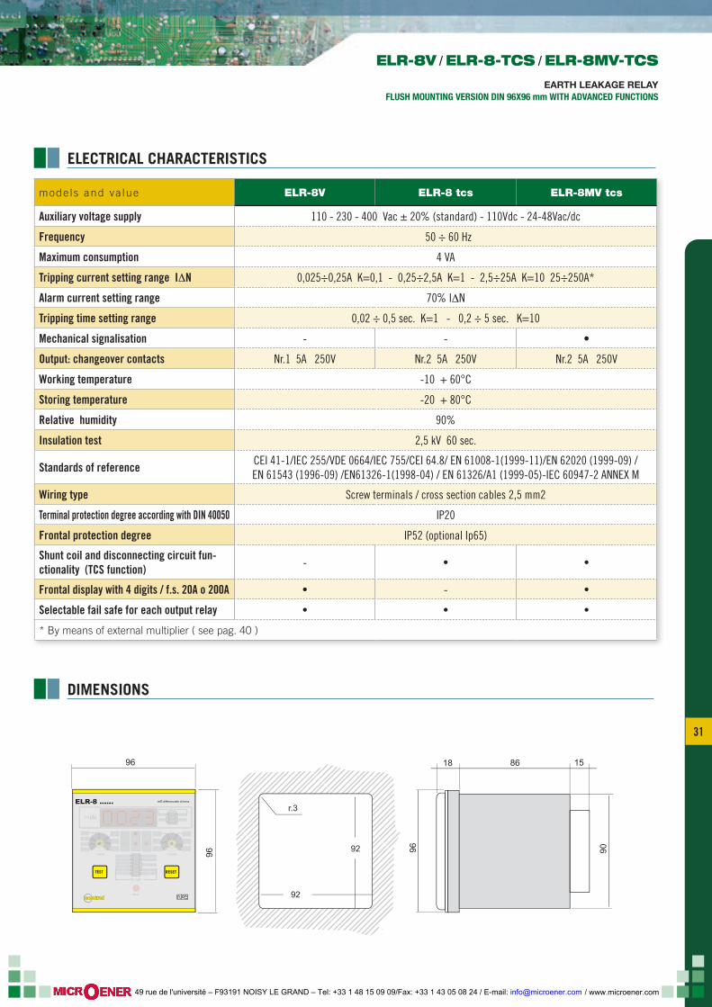
mode ls and va lue ELR-8V ELR-8 tcs ELR-8MV tcs
Auxiliary voltage supply 110 - 230 - 400 Vac ± 20% (standard) - 110Vdc - 24-48Vac/dc
Frequency 50 ÷ 60 Hz
Maximum consumption 4 VA
Tripping current setting range I∆N 0,025÷0,25A K=0,1 - 0,25÷2,5A K=1 - 2,5÷25A K=10 25÷250A*
Alarm current setting range 70% I∆N
Tripping time setting range 0,02 ÷ 0,5 sec. K=1 - 0,2 ÷ 5 sec. K=10
Mechanical signalisation - - •
Output: changeover contacts Nr.1 5A 250V Nr.2 5A 250V Nr.2 5A 250V
Working temperature -10 + 60°C
Storing temperature -20 + 80°C
Relative humidity 90%
Insulation test 2,5 kV 60 sec.
Standards of reference CEI 41-1/IEC 255/VDE 0664/IEC 755/CEI 64.8/ EN 61008-1(1999-11)/EN 62020 (1999-09) /EN 61543 (1996-09) /EN61326-1(1998-04) / EN 61326/A1 (1999-05)-IEC 60947-2 ANNEX M
Wiring type Screw terminals / cross section cables 2,5 mm2
Terminal protection degree according with DIN 40050 IP20
Frontal protection degree IP52 (optional Ip65)
Shunt coil and disconnecting circuit fun-ctionality (TCS function) - • •
Frontal display with 4 digits / f.s. 20A o 200A • - •
Selectable fail safe for each output relay • • •
* By means of external multiplier ( see pag. 40 )
ΙΔn(A) t (sec)
TEST RESET
ΙΔx0,1
tx1alarm on
FS tripFS alarm
ΙΔx1ΙΔx10
tx10alarm off
ON TRIPALARM
off
FAIL SAFE
200A
OFF
20A
ON
HOLD
ΙΔ(A)
1
0,6
0,3
1,5 0,2
0,1
0,03
0,3
0,4
0,5
off
contrel
2
2,5
3
relË differenziale di terraELR-8MV-TCS
TCS
MEM.
96
96
15
9096
861896
96
92
92
r.3
ΙΔn(A) t (sec)
TEST RESET
ΙΔx0,1
tx1alarm on
FS tripFS alarm
ΙΔx1ΙΔx10ΔΔ
tx10alarm off
ON TRIPALARM
off
FAIL SAFE
200A
OFF
20A
ON
HOLD
ΙΔ(A)
1
0,6
0,3
1,5 0,2
0,1
0,03
0,3
0,4
0,5
off
2
2,5
3
relË differenziale di terraELR-8 ......
TCS
MEM.contrel
ELECTRICAL CHARACTERISTICS
DIMENSIONS
ELR-8V / ELR-8-TCS / ELR-8MV-TCS
EARTH LEAKAGE RELAYFLUSH MOUNTING VERSION DIN 96X96 mm WITH ADVANCED FUNCTIONS
/ www.microener.com 49 rue de l'université – F93191 NOISY LE GRAND – Tel: +33 1 48 15 09 09/Fax: +33 1 43 05 08 24 / E-mail: [email protected]
32
ΙΔn(A) t (sec)
TEST RESET
ΙΔx0,1
tx1alarm on
FS tripFS alarm
ΙΔx1ΙΔx10
tx10alarm off
ON TRIPALARM
off
FAIL SAFE
1
0,6
0,3
1,5 0,2
0,1
0,03
0,3
0,4
0,5
off
2
2,5
3
relè differenziale di terra / earh leakage relayELR-8-TCS
TCS
ΙΔn(A) t (sec)
TEST RESET
ΙΔx0,1
tx1alarm on
FS tripFS alarm
ΙΔx1ΙΔx10
tx10alarm off
ON TRIPALARM
off
FAIL SAFE
200A
OFF
20A
ON
HOLD
ΙΔ(A)
1
0,6
0,3
1,5 0,2
0,1
0,03
0,3
0,4
0,5
off
2
2,5
3
relè differenziale di terraELR-8MV-TCS
TCS
MEM.contrel
contrel
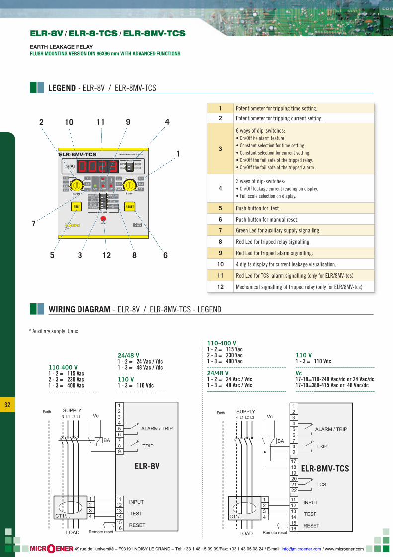
1 Potentiometer for tripping time setting.
2 Potentiometer for tripping current setting.
3
6 ways of dip-switches:• On/Off he alarm feature .• Constant selection for time setting.• Constant selection for current setting.• On/Off the fail safe of the tripped relay.• On/Off the fail safe of the tripped alarm.
43 ways of dip-switches:• On/Off leakage current reading on display.• Full scale selection on display.
5 Push button for test.
6 Push button for manual reset.
7 Green Led for auxiliary supply signalling.
8 Red Led for tripped relay signalling.
9 Red Led for tripped alarm signalling.
10 4 digits display for current leakage visualisation.
11 Red Led for TCS alarm signalling (only for ELR/8MV-tcs)
12 Mechanical signalling of tripped relay (only for ELR/8MV-tcs)
LEGEND - ELR-8V / ELR-8MV-TCS
WIRING DIAGRAM - ELR-8V / ELR-8MV-TCS - LEGEND
63 8125
2
7
11 9 410
1
ELR-8V / ELR-8-TCS / ELR-8MV-TCS
EARTH LEAKAGE RELAYFLUSH MOUNTING VERSION DIN 96X96 mm WITH ADVANCED FUNCTIONS
123456789
171819202122
141516
111213
ALARM / TRIP
TRIP
TCS
INPUT
TEST
RESET
ELR-8MV-TCS
INSERZIONE CON BOBINA DI APERTURA
Remote reset
1234CT1/...3
N L1 L2 L3 Vc
BA
ELR-8-TCS
LOAD
SUPPLYEarth
123456789
141516
111213
ALARM / TRIP
TRIP
INPUT
TEST
RESET
ELR-8VINSERZIONE CON BOBINA DI APERTURA
Remote reset
1234CT1/...
LOAD
3
N L1 L2 L3SUPPLYEarth
Vc
BA
110-400 V1 - 2 = 115 Vac2 - 3 = 230 Vac1 - 3 = 400 Vac-------------------------
24/48 V1 - 2 = 24 Vac / Vdc1 - 3 = 48 Vac / Vdc-------------------------110 V1 - 3 = 110 Vdc-------------------------
110-400 V1 - 2 = 115 Vac2 - 3 = 230 Vac1 - 3 = 400 Vac---------------------------------24/48 V1 - 2 = 24 Vac / Vdc1 - 3 = 48 Vac / Vdc----------------------------------------
110 V1 - 3 = 110 Vdc----------------------------------------Vc17-18=110-240 Vac/dc or 24 Vac/dc17-19=380-415 Vac or 48 Vac/dc----------------------------------------
* Auxiliary supply Uaux
ELR-8V ELR-8MV-TCS
/ www.microener.com 49 rue de l'université – F93191 NOISY LE GRAND – Tel: +33 1 48 15 09 09/Fax: +33 1 43 05 08 24 / E-mail: [email protected]
33 33
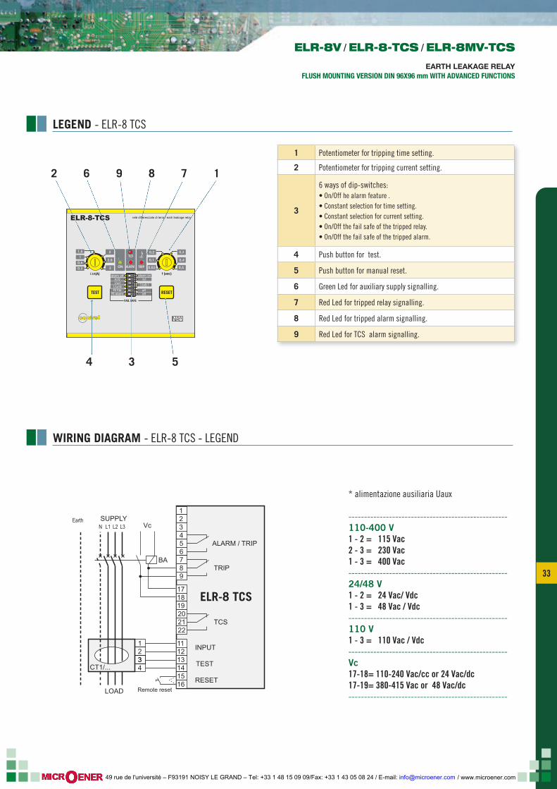
LEGEND - ELR-8 TCS
1 Potentiometer for tripping time setting.
2 Potentiometer for tripping current setting.
3
6 ways of dip-switches:• On/Off he alarm feature .• Constant selection for time setting.• Constant selection for current setting.• On/Off the fail safe of the tripped relay.• On/Off the fail safe of the tripped alarm.
4 Push button for test.
5 Push button for manual reset.
6 Green Led for auxiliary supply signalling.
7 Red Led for tripped relay signalling.
8 Red Led for tripped alarm signalling.
9 Red Led for TCS alarm signalling.
WIRING DIAGRAM - ELR-8 TCS - LEGEND
ΙΔn(A) t (sec)
TEST RESET
ΙΔx0,1
tx1alarm on
FS tripFS alarm
ΙΔx1ΙΔx10
tx10alarm off
ON TRIPALARM
off
FAIL SAFE
1
0,6
0,3
1,5 0,2
0,1
0,03
0,3
0,4
0,5
off
2
2,5
3
relè differenziale di terra / earh leakage relayELR-8-TCS
TCS
ΙΔn(A) t (sec)
TEST RESET
ΙΔx0,1
tx1alarm on
FS tripFS alarm
ΙΔx1ΙΔx10
tx10alarm off
ON TRIPALARM
off
FAIL SAFE
200A
OFF
20A
ON
HOLD
ΙΔ(A)
1
0,6
0,3
1,5 0,2
0,1
0,03
0,3
0,4
0,5
off
2
2,5
3
relè differenziale di terraELR-8MV-TCS
TCS
MEM.contrel
contrel
534
2 6 9 8 7 1
ELR-8V / ELR-8-TCS / ELR-8MV-TCS
EARTH LEAKAGE RELAYFLUSH MOUNTING VERSION DIN 96X96 mm WITH ADVANCED FUNCTIONS
123456789
171819202122
141516
111213
ALARM / TRIP
TRIP
TCS
INPUT
TEST
RESET
ELR-8MV-TCS
INSERZIONE CON BOBINA DI APERTURA
Remote reset
1234CT1/...3
N L1 L2 L3 Vc
BA
ELR-8-TCS
LOAD
SUPPLYEarth
* alimentazione ausiliaria Uaux
---------------------------------------------------110-400 V1 - 2 = 115 Vac2 - 3 = 230 Vac1 - 3 = 400 Vac---------------------------------------------------24/48 V1 - 2 = 24 Vac/ Vdc1 - 3 = 48 Vac / Vdc---------------------------------------------------110 V1 - 3 = 110 Vac / Vdc---------------------------------------------------Vc17-18= 110-240 Vac/cc or 24 Vac/dc17-19= 380-415 Vac or 48 Vac/dc---------------------------------------------------
ELR-8 TCS
/ www.microener.com 49 rue de l'université – F93191 NOISY LE GRAND – Tel: +33 1 48 15 09 09/Fax: +33 1 43 05 08 24 / E-mail: [email protected]
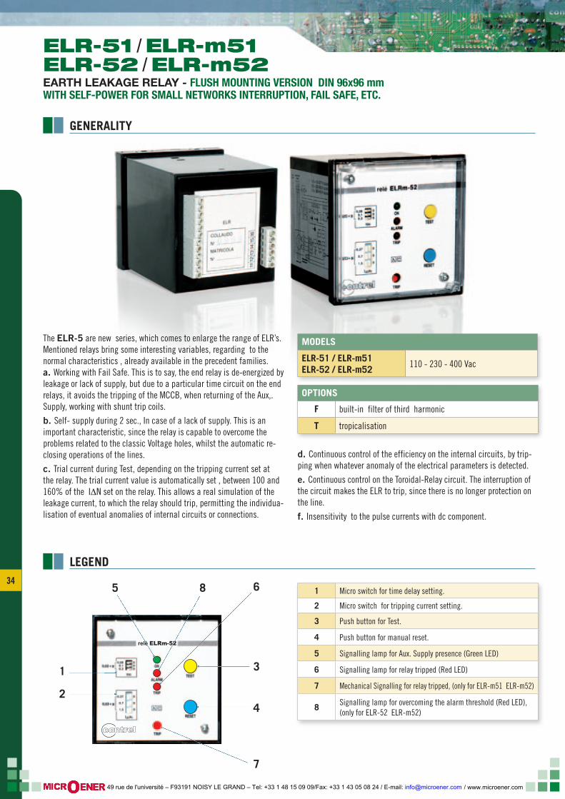
34
LEGEND
1 Micro switch for time delay setting.
2 Micro switch for tripping current setting.
3 Push button for Test.
4 Push button for manual reset.
5 Signalling lamp for Aux. Supply presence (Green LED)
6 Signalling lamp for relay tripped (Red LED)
7 Mechanical Signalling for relay tripped, (only for ELR-m51 ELR-m52)
8 Signalling lamp for overcoming the alarm threshold (Red LED), (only for ELR-52 ELR-m52)
OPTIONS
F built-in filter of third harmonic
T tropicalisation
MODELS
ELR-51 / ELR-m51ELR-52 / ELR-m52 110 - 230 - 400 Vac
The ELR-5 are new series, which comes to enlarge the range of ELR’s. Mentioned relays bring some interesting variables, regarding to the normal characteristics , already available in the precedent families.a. Working with Fail Safe. This is to say, the end relay is de-energized by leakage or lack of supply, but due to a particular time circuit on the end relays, it avoids the tripping of the MCCB, when returning of the Aux,.Supply, working with shunt trip coils.
b. Self- supply during 2 sec., In case of a lack of supply. This is an important characteristic, since the relay is capable to overcome the problems related to the classic Voltage holes, whilst the automatic re-closing operations of the lines.
c. Trial current during Test, depending on the tripping current set at the relay. The trial current value is automatically set , between 100 and 160% of the I∆N set on the relay. This allows a real simulation of the leakage current, to which the relay should trip, permitting the individua-lisation of eventual anomalies of internal circuits or connections.
d. Continuous control of the efficiency on the internal circuits, by trip-ping when whatever anomaly of the electrical parameters is detected.
e. Continuous control on the Toroidal-Relay circuit. The interruption of the circuit makes the ELR to trip, since there is no longer protection on the line.
f. Insensitivity to the pulse currents with dc component.
relè ELRm-52
contrel
1
2
5 8
3
6
4
7
ELR-51 / ELR-m51ELR-52 / ELR-m52EARTH LEAKAGE RELAY - FLUSH MOUNTING VERSION DIN 96x96 mm WITH SELF-POWER FOR SMALL NETWORKS INTERRUPTION, FAIL SAFE, ETC.
GENERALITY
/ www.microener.com 49 rue de l'université – F93191 NOISY LE GRAND – Tel: +33 1 48 15 09 09/Fax: +33 1 43 05 08 24 / E-mail: [email protected]
35 35
LOAD
Aux
N R S TSUPPLY
Ba
Earth
21
34
9
1211
141516
13
8
M
AlarmON
Trip
Trip
x1 x10
x10
I ∆I ∆0,02÷0,5
7 6 5 3 2 1
RemoteReset
Reset
0,5
M
ELR-51 ELR-m51
Aux
N R S T
Ba
21
34
9
1211
141516
13
8
M
ONTrip Trip
x1 x10
x10
I ∆I ∆0,02÷0,5
7 6 5 3 2 1
Reset
ELR-52 ELR-m52
LOAD
SUPPLYEarth
RemoteReset
15
9096
861896
96
92
92
r.3relè ELRm-52
contrel
mode ls and va lue ELR- 51 ELRm-51 ELR-52 ELRm-52
Auxiliary voltage supply 110-230-400 V ac. ± 20%
Frequency 50 ÷ 60 Hz
Maximum consumption 4 VA
Tripping current setting range I∆N 0,03÷2,5 0,3÷25A*
Alarm current setting range - 70%
Time tripping setting range 0,02 ÷ 0,5 sec.
Mechanical signalisation - • - •
Output: 2 change-over contacts 5A 250V
Working temperature -10 + 60°C
Storing temperature -20 + 80°C
Relative humidity 90%
Insulation Test 2,5 kV 60 sec.
Standards CEI 41-1/IEC 255/VDE 0664/IEC 755/CEI 64.8/ EN 61008-1(1999-11)/EN 62020 (1999-09) /EN 61543 (1996-09) /EN61326-1(1998-04) / EN 61326/A1 (1999-05)-IEC 60947-2 ANNEX M / AS 2081-1 / AS 2081-3
Wiring method Screw terminals for cross section wire 2,5 mm2
Protection degree at terminals according with DIN 40050 IP 20
Frontal protection degree Ip52 (optional IP54)
* By means of external multiplier ( see pag. 40 )
1 - 2 = 110-127 Vac2 - 3 = 220-240 Vac1 - 3 = 380-415 Vac
1 - 2 = 110-127 Vac2 - 3 = 220-240 Vac1 - 3 = 380-415 Vac
ELECTRICAL CHARACTERISTICS
WIRING DIAGRAM - LEGEND
DIMENSIONS
ELR-51 / ELR-m51 / ELR-52 / ELR-m52
EARTH LEAKAGE RELAYFLUSH MOUNTING VERSION DIN 96x96 mm
WITH SELF-POWER FOR SMALL NETWORKS INTERRUPTION, FAIL SAFE, ETC.
/ www.microener.com 49 rue de l'université – F93191 NOISY LE GRAND – Tel: +33 1 48 15 09 09/Fax: +33 1 43 05 08 24 / E-mail: [email protected]
36
Type
Characteristics
* only 230 Vca ** only 110-230 Vca
MECHANICALFlush mountingDIN rail mountingBase plate mountingMechanical signallingAlarm at 70% of the set currentTECHNICALFunction select 2nd contact (trip or alarm)Selectable fail safe kFrontal displayTCS functionBuilt-in Toroid TransformerAutomatic reset and reclosingAUXILIARY SUPPLY12V ac/dc24-48V ac/dc110V dc110 / 240 / 415 VacFrequenza 50-60 HzSELF CONSUMPTIONMaximum 3VAMinimum 4VATRIP CURRENT SETTING0,025÷25A0,25A÷250A op.0,03÷2,5A0,3÷25A opz.0,03 o 0,5A0,03-0,1-0,3-0,5-1ATRIP TIME SETTING0,02÷5 sec.0,02÷0,5 sec.0,02 o 5 sec.0,02-0,2-,05-1-5sec.OUTPUT CONTACTSMax: 5A-250V1 changeover for tripping2 changeover for tripping1 changeover for alarm1 changeover for alarm TCSTEMPERATUREStoring: -20 ÷ +80°CWorking: -10 ÷ +60°CRelative humidity: 90%INSULATION TEST2,5 kV per 60 secSTANDARDS OF REFERENCECEI 41-1/IEC 255/VDE 0664/IEC 755/CEI 64.8/ EN 610081(1999-11)/EN 62020 (1999-09)/EN 61543 (1996-09) /EN613261(1998-04) / EN 61326/A1 (1999-05)/IEC 60947-2 ANNEX M
AS 2081-1AS 2081-3GRADO DI PROTEZIONEIP20 IP54 (option)
ELR
-1E
ELR
-2EL
R-2
MEL
R-8
VEL
R-8
tcs
ELR
-8M
Vtc
sEL
R-9
1EL
R-9
2EL
R-4
.0EL
Rm
-4.0
ELR
-4v
ELR
m-4
VEL
R7
ELR
-51
ELR
m-5
1EL
R-5
2EL
Rm
-52
ELR
C-1
ELR
-3C
ELR
-3F
ELR
-3E
ELR
-61
ELR
m-6
1EL
R-6
2EL
Rm
-62
ELR
-CB
ELR
-DL
ELR
-DL2
MEL
RC
-BL
selection table
EARTH LEAKAGE RELAY
/ www.microener.com 49 rue de l'université – F93191 NOISY LE GRAND – Tel: +33 1 48 15 09 09/Fax: +33 1 43 05 08 24 / E-mail: [email protected]
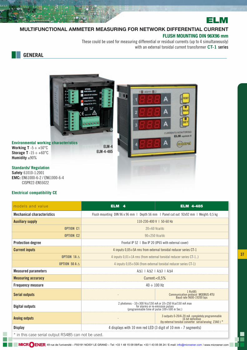
37 37
ELM-4ELM-4-485
GENERAL
ELMMULTIFUNCTIONAL AMMETER MEASURING FOR NETWORK DIFFERENTIAL CURRENT
FLUSH MOUNTING DIN 96X96 mm These could be used for measuring differential or residual currents (up to 4 simultaneously)
with an external toroidal current transformer CT-1 series
mode ls and va lue ELM 4 ELM 4-485
Mechanical characteristics Flush mounting DIN 96 x 96 mm | Depth 56 mm | Panel cut out 92x92 mm | Weight: 0,5 kg
Auxiliary supply 110-230-400 V | 50-60 Hz
OPTION C1 20÷60 Vca/dc
OPTION C2 90÷250 Vca/dc
Protection degree Frontal IP 52 | Box IP 20 (IP65 with external cover)
Current inputs 4 inputs 0,05÷5A rms from external toroidal reducer series CT-1
OPTION 1A ∆ 4 inputs 0,01÷1A rms (from external toroidal reducer series CT-1..)
OPTION 50 A ∆ 4 inputs 0,05÷50A (from external toroidal reducer series CT-1)
Measured parameters A∆1 | A∆2 | A∆3 | A∆4
Measuring accuracy Current:<0,5%
Frequency measure 40 ÷ 100 Hz
Serial outputs -1 Rs485
Communication protocol MODBUS-RTU Baud rate 9600-19200 bps
Digital outputs2 photomos - 10÷300 Vcc/150 mA or 10÷250 Vca/150 mA max
for alarms or re-emission pulses (programmable time of pulse 100÷500 m Sec.)
Analog outputs -3 outputs 0-20/4-20 mA completely programmable
16 bit definition(by external toroidal converter serial/analog Z3AO ) *
Display 4 displays with 10 mm red LED (3 digit of 10 mm - 7 segments)
* in this case serial output RS485 can not be used.
Environmental working characteristicsWorking T -5 ÷ +50°CStorage T -15 ÷ +60°CHumidity ≤90%
Standards/ RegulationSafety 61010-1:2001 EMC: EN61000-6-2 / EN61000-6-4 CISPR22-EN55022
Electrical compatibility CE
/ www.microener.com 49 rue de l'université – F93191 NOISY LE GRAND – Tel: +33 1 48 15 09 09/Fax: +33 1 43 05 08 24 / E-mail: [email protected]

38
CT-1TOROIDAL CURRENT TRANSFORMERS
The CT series toroidal transformers allow to sense the leaking currents to earth. These transformers have been designed to be coupled to the maximum earth leakage current relays of the ELR series.The T/T’s should be installed upstream of the lines or loads to be protected and/or supervised. All active wires (phase and neutral) of the three phase or single phase lines should pass through the internal core of the transformers. It senses, in this way, the cur-rents vectorial addition, in order to transmit the earth leakage cur-rent to te secondary.For further applications of the CT toroidal transformers, please re-fer tao the specific documentation ( I.e. The sensing of the earth leakage current on the distribution transformers).
The current T/T’s are made of an optimum quality magnetic core, which allows to detect leakage currents of a very low value even. There are two windings coupled in the core, one to detect the si-gnal of a leakage in the line ( to be sent to the relay), and the other for performing the Test. The eventual Test which uses this second winding is performed through various specific ELR’s types. A signal from the ELR is sent to the Test winding. This signal generates a flow equivalent to a leakage, which is detected by other winding and resent to the relay and makes it to trip. The selection of the transformer should be made on basis of the dimensions of the wires or bars that should pass through its inner hole. There are split core types available, which allow their instal-lation without disconnecting the actual wiring.
CT-1/415
CTD-1/28
CT-1/210CTA-1/210
CT-1/35, CT-1/60, CT-1/80, CT-1/110, CT-1/160, CTA-1/160
GENERALITY
/ www.microener.com 49 rue de l'université – F93191 NOISY LE GRAND – Tel: +33 1 48 15 09 09/Fax: +33 1 43 05 08 24 / E-mail: [email protected]
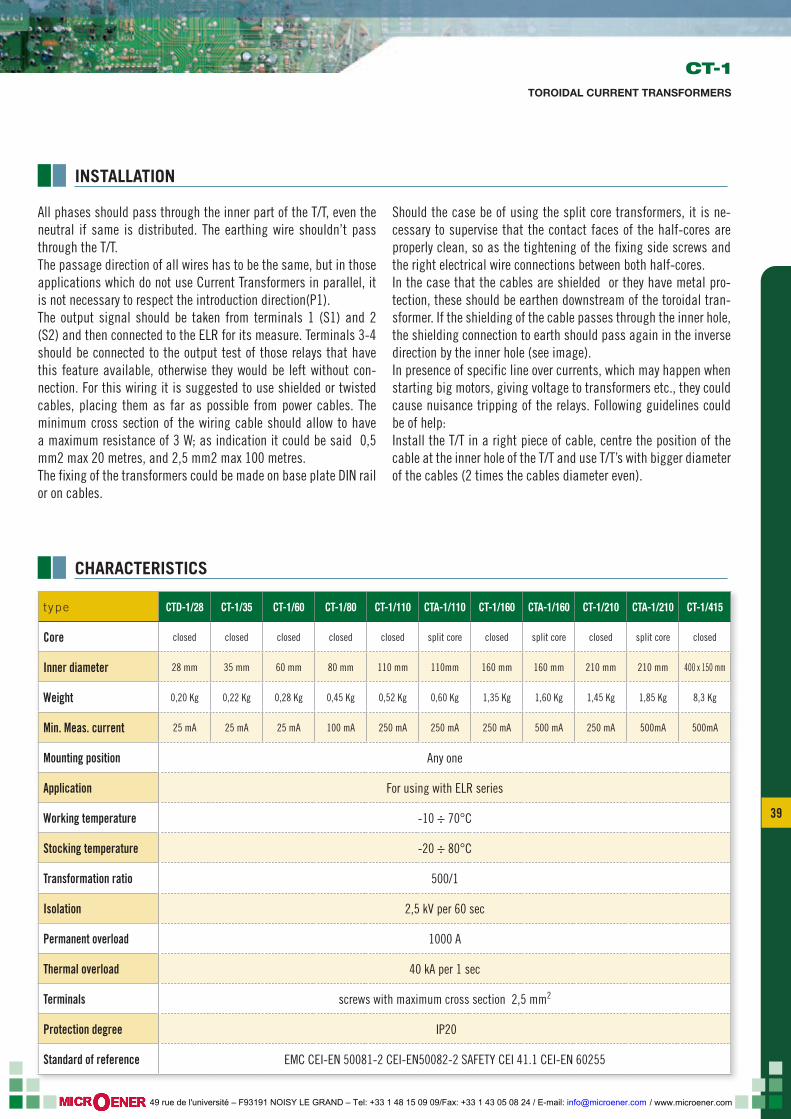
39 39
CT-1TOROIDAL CURRENT TRANSFORMERS
t ype CTD-1/28 CT-1/35 CT-1/60 CT-1/80 CT-1/110 CTA-1/110 CT-1/160 CTA-1/160 CT-1/210 CTA-1/210 CT-1/415
Core closed closed closed closed closed split core closed split core closed split core closed
Inner diameter 28 mm 35 mm 60 mm 80 mm 110 mm 110mm 160 mm 160 mm 210 mm 210 mm 400 x 150 mm
Weight 0,20 Kg 0,22 Kg 0,28 Kg 0,45 Kg 0,52 Kg 0,60 Kg 1,35 Kg 1,60 Kg 1,45 Kg 1,85 Kg 8,3 Kg
Min. Meas. current 25 mA 25 mA 25 mA 100 mA 250 mA 250 mA 250 mA 500 mA 250 mA 500mA 500mA
Mounting position Any one
Application For using with ELR series
Working temperature -10 ÷ 70°C
Stocking temperature -20 ÷ 80°C
Transformation ratio 500/1
Isolation 2,5 kV per 60 sec
Permanent overload 1000 A
Thermal overload 40 kA per 1 sec
Terminals screws with maximum cross section 2,5 mm2
Protection degree IP20
Standard of reference EMC CEI-EN 50081-2 CEI-EN50082-2 SAFETY CEI 41.1 CEI-EN 60255
INSTALLATION
All phases should pass through the inner part of the T/T, even the neutral if same is distributed. The earthing wire shouldn’t pass through the T/T. The passage direction of all wires has to be the same, but in those applications which do not use Current Transformers in parallel, it is not necessary to respect the introduction direction(P1). The output signal should be taken from terminals 1 (S1) and 2 (S2) and then connected to the ELR for its measure. Terminals 3-4 should be connected to the output test of those relays that have this feature available, otherwise they would be left without con-nection. For this wiring it is suggested to use shielded or twisted cables, placing them as far as possible from power cables. The minimum cross section of the wiring cable should allow to have a maximum resistance of 3 W; as indication it could be said 0,5 mm2 max 20 metres, and 2,5 mm2 max 100 metres.The fixing of the transformers could be made on base plate DIN rail or on cables.
Should the case be of using the split core transformers, it is ne-cessary to supervise that the contact faces of the half-cores are properly clean, so as the tightening of the fixing side screws and the right electrical wire connections between both half-cores.In the case that the cables are shielded or they have metal pro-tection, these should be earthen downstream of the toroidal tran-sformer. If the shielding of the cable passes through the inner hole, the shielding connection to earth should pass again in the inverse direction by the inner hole (see image).In presence of specific line over currents, which may happen when starting big motors, giving voltage to transformers etc., they could cause nuisance tripping of the relays. Following guidelines could be of help:Install the T/T in a right piece of cable, centre the position of the cable at the inner hole of the T/T and use T/T’s with bigger diameter of the cables (2 times the cables diameter even).
CHARACTERISTICS
/ www.microener.com 49 rue de l'université – F93191 NOISY LE GRAND – Tel: +33 1 48 15 09 09/Fax: +33 1 43 05 08 24 / E-mail: [email protected]
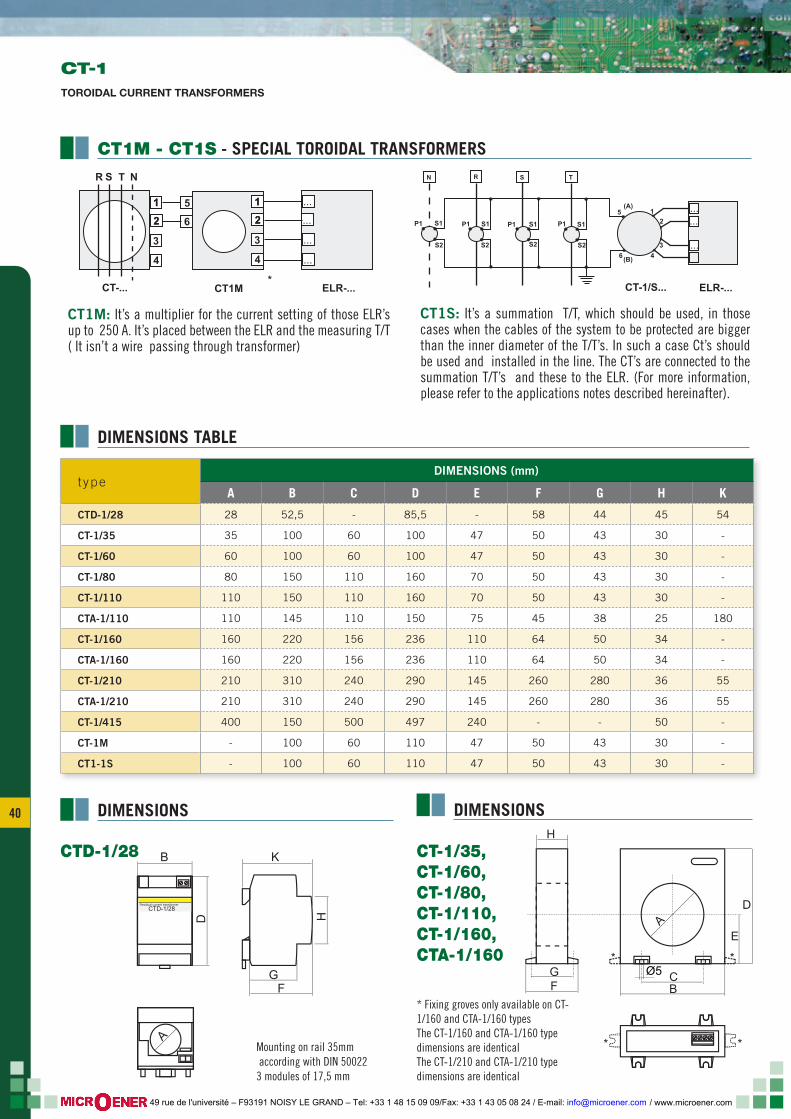
40
BCØ5
AE
D
GF
*
* *
*
H
HK
A
BFC
EDG
5
CT-1/35, CT-1/60, CT-1/80 CT-1/110 CT-1/160 CTA-1/160
H
GF
E
D
BC
A
Ø5
K
CTA-1/110
CT-1/210 CTA-1/210le dimensioni dei modelli CT-1/210 e CTA-1/210 sono identiche
*asole di fissaggio disponibili solo sui modelli CT-1/160 e CTA-1/160 Le dimensioni dei modelli CT-1/160 e CTA-1/160 sono identiche
CTA-1/210
F G
H
KB
D
CTD-1/28Residual current transformer
A
CTD-1/28
montaggio su profilato 35mm secondo DIN 50022 3 moduli da 17,5 mm
25
C
E
S1S1
S2Test
1,5mm
3mm
H
A
B
D
t ypeDIMENSIONS (mm)
A B C D E F G H K
CTD-1/28 28 52,5 - 85,5 - 58 44 45 54
CT-1/35 35 100 60 100 47 50 43 30 -
CT-1/60 60 100 60 100 47 50 43 30 -
CT-1/80 80 150 110 160 70 50 43 30 -
CT-1/110 110 150 110 160 70 50 43 30 -
CTA-1/110 110 145 110 150 75 45 38 25 180
CT-1/160 160 220 156 236 110 64 50 34 -
CTA-1/160 160 220 156 236 110 64 50 34 -
CT-1/210 210 310 240 290 145 260 280 36 55
CTA-1/210 210 310 240 290 145 260 280 36 55
CT-1/415 400 150 500 497 240 - - 50 -
CT-1M - 100 60 110 47 50 43 30 -
CT1-1S - 100 60 110 47 50 43 30 -
DIMENSIONS TABLE
CT-1TOROIDAL CURRENT TRANSFORMERS
CT1M: It’s a multiplier for the current setting of those ELR’s up to 250 A. It’s placed between the ELR and the measuring T/T ( It isn’t a wire passing through transformer)
CT1S: It’s a summation T/T, which should be used, in those cases when the cables of the system to be protected are bigger than the inner diameter of the T/T’s. In such a case Ct’s should be used and installed in the line. The CT’s are connected to the summation T/T’s and these to the ELR. (For more information, please refer to the applications notes described hereinafter).
DIMENSIONS DIMENSIONS
CT1M - CT1S - SPECIAL TOROIDAL TRANSFORMERS
* Fixing groves only available on CT-1/160 and CTA-1/160 typesThe CT-1/160 and CTA-1/160 type dimensions are identicalThe CT-1/210 and CTA-1/210 type dimensions are identical
Mounting on rail 35mm according with DIN 500223 modules of 17,5 mm
1 11 15
2 22 26
3 3
4 4
ELR-...CT1MCT-...
...
...
...
...
R S T N
*
P1
N R S T
P1P1 P1S1 S1S1 S1
5
6
(A)
(B)
CT-1/S...
1
2
3
4
S2 S2S2 S2
ELR-...
...
...
...
...
CT-1/35, CT-1/60, CT-1/80, CT-1/110, CT-1/160, CTA-1/160
CTD-1/28
/ www.microener.com 49 rue de l'université – F93191 NOISY LE GRAND – Tel: +33 1 48 15 09 09/Fax: +33 1 43 05 08 24 / E-mail: [email protected]
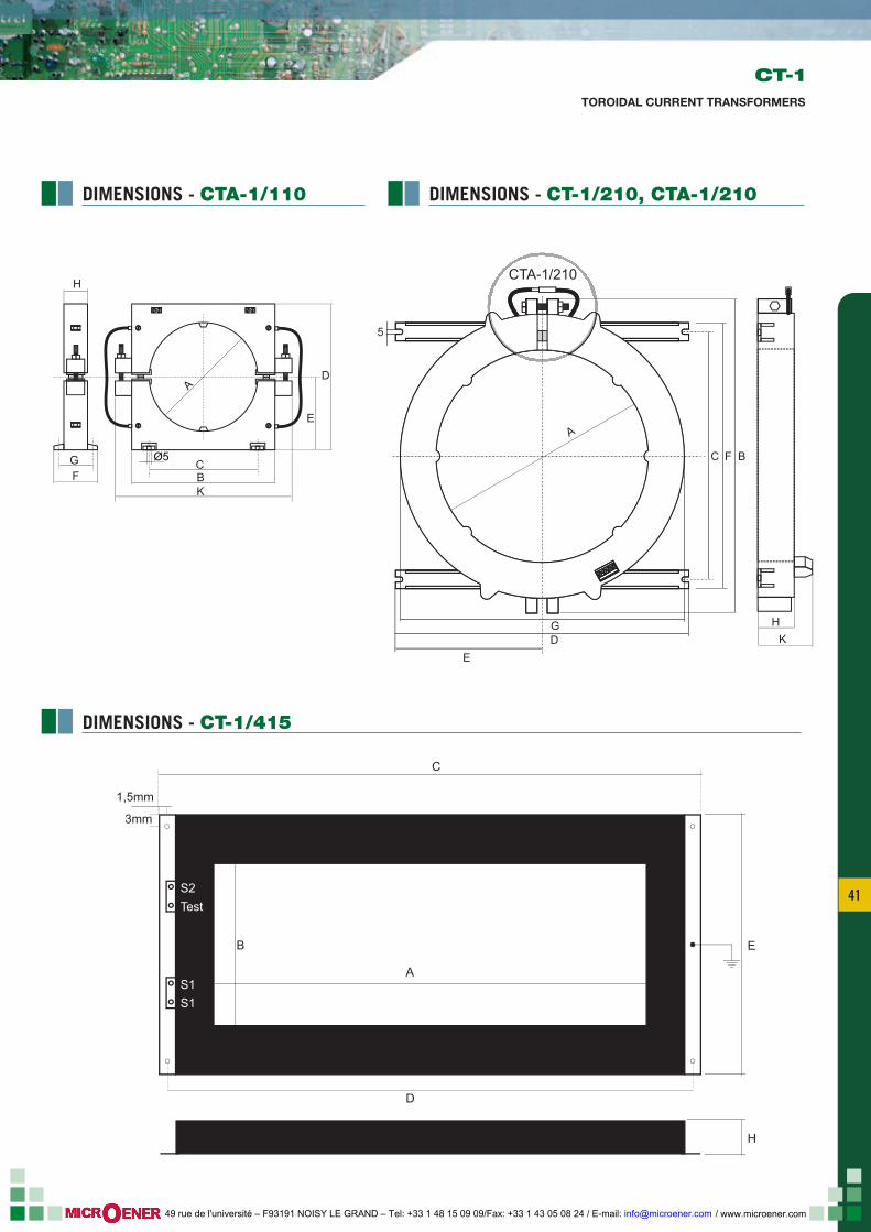
41 41
CT-1TOROIDAL CURRENT TRANSFORMERS
BCØ5
AE
D
GF
*
* *
*
H
HK
A
BFC
EDG
5
CT-1/35, CT-1/60, CT-1/80 CT-1/110 CT-1/160 CTA-1/160
H
GF
E
D
BC
A
Ø5
K
CTA-1/110
CT-1/210 CTA-1/210le dimensioni dei modelli CT-1/210 e CTA-1/210 sono identiche
*asole di fissaggio disponibili solo sui modelli CT-1/160 e CTA-1/160 Le dimensioni dei modelli CT-1/160 e CTA-1/160 sono identiche
CTA-1/210
F G
H
KB
D
CTD-1/28Residual current transformer
A
CTD-1/28
montaggio su profilato 35mm secondo DIN 50022 3 moduli da 17,5 mm
25
C
E
S1S1
S2Test
1,5mm
3mm
H
A
B
D
DIMENSIONS - CT-1/415
DIMENSIONS - CTA-1/110 DIMENSIONS - CT-1/210, CTA-1/210
/ www.microener.com 49 rue de l'université – F93191 NOISY LE GRAND – Tel: +33 1 48 15 09 09/Fax: +33 1 43 05 08 24 / E-mail: [email protected]
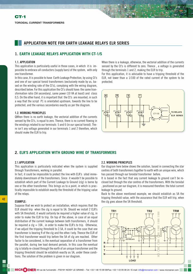
42
APPLICATION NOTE FOR EARTH LEAKAGE RELAYS ELR SERIES
1.1. APPLICATIONThis application is particularly useful in those cases, in which it is im-possible to embrace all conductors (supply bars) of the system, with only one transformer.In this case, It is possible to have Earth Leakage Protection, by using Ct’s and one of our special toroid transformers (exclusively made by us, ba-sed on the winding rate of the Ct’s), complying with the wiring diagram, described below. For this application the Ct’s should have: the same tran-sformation ratio (5A secondary), same power (10 VA at least) and class 0,5. On the other hand, it is important that the Ct’s are mounted, in such a way that the script P1 is orientated upstream, towards the line to be protected, and the various secondaries exactly as per the diagram.
1.2. WORKING PRINCIPLESQWhen there is no earth leakage, the vectorial addition of the currents sensed by the Ct’s, is equal to zero. Thence, there is no current flowing in the windings related to our terminals 5 and 6 (in our special toroid). The-re isn’t any voltage generated in our terminals 1 and 2 therefore, which should make the ELR to trip.
When there is a leakage, otherwise, the vectorial addition of the currents sensed by the Ct’s is different to zero. Thence , a voltage is generated through the terminals 1 and 2, making the ELR to trip.For this application, it is advisable to have a tripping threshold of the ELR, not lower than a 1/100 of the rated current of the system to be protected.
2.1.APPLICATIONThis application is particularly indicated when the system is supplied through Transformers, working in parallel.In fact, it could be impossible to protect the line with ELR’s sited imme-diately downstream of the transformers. Since it wouldn’t be possible to establish which part of the Current Leakage to Ground (clg) is borne by one or the other transformer. This brings us to a point, in which is prac-tically impossible to establish exactly the threshold of the tripping value of the relays.
EXAMPLE:Suppose that we wish to protect an installation, which requires that the ELR should trip when the clg is equal to 5A. Should we install 2 ELR’s with 5A threshold, it would certainly be required a higher value of clg, in order to make the ELR to trip. On top of the above, in case of an equal distribution of the current leakage between both transformers, it should be required a clg = 10A , in order to make the ELR’s to trip. Otherwise, if we adjust the tripping threshold to 2.5A, it could be the case that one transformer is bearing fl of the clg and the other ⁄ only. Thence the ELR of the first transformer would trip before the 5A of clg are reached. Other factor to be considered, is the eventual separation of a transformer from the parallel, during low load demand periods. In this case the eventual clg is totally re-closed through the earth of an unique transformer and the tripping threshold should be establish exactly as 5A, under these condi-tions. The solution of the problem is given in our diagram.
2.2. WORKING PRINCIPLESOur diagram here below shows the solution, based in connecting the star centres of both transformers together to earth with an unique wire, which has passed through our toroidal transformer before.It is based in the fact that any current leakage to ground can’t be re-closed but through the star centres of the transformers. With the toroidal , positioned as per our diagram, it is measured therefore the total current leakage to ground. Back to the above mentioned example, we should establish as 5A the tripping threshold value, with the assurance that the ELR will trip, when the clg goes above the 5A threshold.
P1
N R S T
P1P1 P1S1 S1S1 S15
6
(A)
(B)
CT-1/S
1
TO RELAYS
ELR SERIES
2
34
S2 S2S2 S2
1. EARTH LEAKAGE RELAYS APPLICATION WITH CT-1/S
2. ELR’S APPLICATION WITH GROUND WIRE OF TRANSFORMERS
1 1 1
TR1 TR2 TRM
R
LOAD
STN
2 2 2
3
ELR RELAYS
3 34 4 4
CT-1TOROIDAL CURRENT TRANSFORMERS
/ www.microener.com 49 rue de l'université – F93191 NOISY LE GRAND – Tel: +33 1 48 15 09 09/Fax: +33 1 43 05 08 24 / E-mail: [email protected]
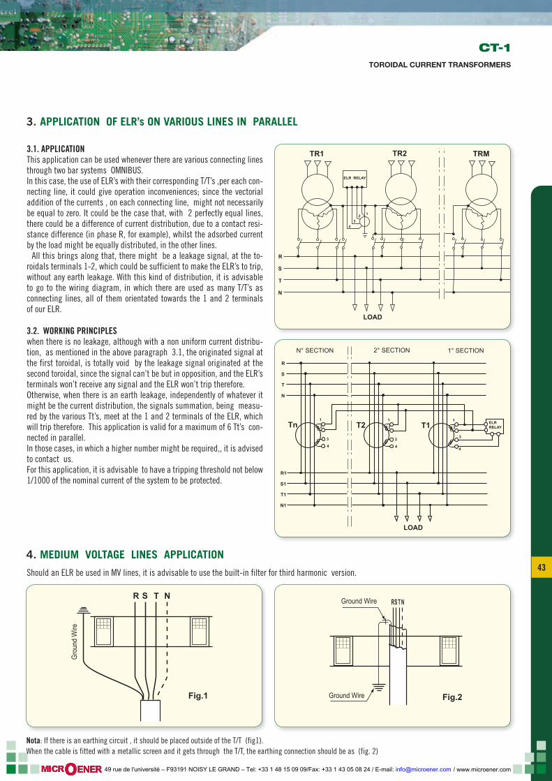
43 43
3.1. APPLICATIONThis application can be used whenever there are various connecting lines through two bar systems OMNIBUS.In this case, the use of ELR’s with their corresponding T/T’s ,per each con-necting line, it could give operation inconveniences; since the vectorial addition of the currents , on each connecting line, might not necessarily be equal to zero. It could be the case that, with 2 perfectly equal lines, there could be a difference of current distribution, due to a contact resi-stance difference (in phase R, for example), whilst the adsorbed current by the load might be equally distributed, in the other lines. All this brings along that, there might be a leakage signal, at the to-roidals terminals 1-2, which could be sufficient to make the ELR’s to trip, without any earth leakage. With this kind of distribution, it is advisable to go to the wiring diagram, in which there are used as many T/T’s as connecting lines, all of them orientated towards the 1 and 2 terminals of our ELR.
3.2. WORKING PRINCIPLESwhen there is no leakage, although with a non uniform current distribu-tion, as mentioned in the above paragraph 3.1, the originated signal at the first toroidal, is totally void by the leakage signal originated at the second toroidal, since the signal can’t be but in opposition, and the ELR’s terminals won’t receive any signal and the ELR won’t trip therefore.Otherwise, when there is an earth leakage, independently of whatever it might be the current distribution, the signals summation, being measu-red by the various Tt’s, meet at the 1 and 2 terminals of the ELR, which will trip therefore. This application is valid for a maximum of 6 Tt’s con-nected in parallel.In those cases, in which a higher number might be required,, it is advised to contact us.For this application, it is advisable to have a tripping threshold not below 1/1000 of the nominal current of the system to be protected.
Should an ELR be used in MV lines, it is advisable to use the built-in filter for third harmonic version.
3. APPLICATION OF ELR’s ON VARIOUS LINES IN PARALLEL
4. MEDIUM VOLTAGE LINES APPLICATION
CT-1TOROIDAL CURRENT TRANSFORMERS
1
ELR RELAY
TR1
R
S
T
N
TR2 TRM
23
4
LOAD
1 1 1
N° SECTION 2° SECTION 1° SECTION
R1
R
S1
S
T1
T
Tn T2 T1
N1
N
2 2 2
3 3 3
4 4 4
ELR RELAY
LOAD
R
Fig.1 Fig.2
Grou
nd W
ire
S T N RS T NGround Wire
Ground Wire
R
Fig.1 Fig.2
Grou
nd W
ire
S T N RS T NGround Wire
Ground Wire
Nota: If there is an earthing circuit , it should be placed outside of the T/T (fig1).When the cable is fitted with a metallic screen and it gets through the T/T, the earthing connection should be as (fig. 2)
/ www.microener.com 49 rue de l'université – F93191 NOISY LE GRAND – Tel: +33 1 48 15 09 09/Fax: +33 1 43 05 08 24 / E-mail: [email protected]
44
TCSRELAY FOR PERMANENT CONTROL OF THE MCCB’S TRIPPING CIRCUIT
GENERALITY
The TCS is devoted to control the MCCB’s disconnection circuits (trip) or the safety circuits. In fact, whenever there is an interrup-tion in a circuit (Output relay of any given protection MCCB’s shunt trip coil and the connection between the relay and the coil), and it is required that the MCCB trips due to any anomaly in the line, such MCCB will be unable to trip.Provided that the system has been installed with other protections, some other Ciruit Breaker will trip and the result will be the loss of service of other sections of the system, which might be most important.Should the MCCB be the sole protection, the use of the TCS is most important, because the working guarantee of the tripping circuit becomes critical, in this particular case.An important application is with the safety or emergency circuits, according with the CEI 64-8/537.4.3 Standard, when using shunt trip coils for emergency reactions , as the starting of a fire fighting
system, por example.The relay has an auxiliary supply electrically separated from the Control Voltage. In normal conditions, with auxiliary supply to the TCS relay, the OK green LED will glow. If there is any anomaly on the disconnection or safety circuit, the “ALARM” red LED will glow and the OK green LED will be switched off.The double changeover end relay will be de-energized enabling a possible acustic signal and a remote repetition. Same signal is shown with tripped breaker.On top of the above it is possible to detect the loss of supply on the auxiliary circuits, by supplying the TCS with same auxiliary vol-tage.If the end relay is normally energized (fail safe), when there is a lack of supply , the end relay will be de-energized, as per anomaly situations, but in this case the LED’s at the front will be switched off.
MODELS
TCS1 circuits 24-48Vac/dc / esec. DIN rail 3 modules
TCS2 circuits 110-230-400Vac/dc / esec. DIN rail 3 modules
MODELS
TCS3 circuits 24-48Vac/dc / esec. flush mounting DIN 96x96mm
TCS4 circuits 110-230-400Vac/dc / esec. flush mounting DIN 96x96mm
TCS-1 / TCS-2 TCS-3 / TCS-4
OPTIONS
T tropicalization
OPTIONS
T tropicalization
/ www.microener.com 49 rue de l'université – F93191 NOISY LE GRAND – Tel: +33 1 48 15 09 09/Fax: +33 1 43 05 08 24 / E-mail: [email protected]
45 45
ELECTRICAL CHARACTERISTICS
TCS
RELAY FOR PERMANENT CONTROL OF THE MCCB’S TRIPPING CIRCUIT
mode ls and va lue TCS-1 TCS-2 TCS-3 TCS-4
Auxiliary Voltage supply 24÷48 Vac/dc ± 20% 110-230-400Vac/dc ± 20% 24÷48 Vac/dc ± 20% 110-230-400Vac/dc ± 20%
Frequency 50 ÷ 60 Hz
Maximum consumption 1,5÷3,5VA depending on Vaux
Current of circuit under control 6 mA 2 mA 110-380V 4mA 220V 6 mA 2 mA 110-380V 4mA 220V
Voltage of circuit under control 13÷30V ac/dc 8-9 terminals 24÷60V ac/dc 7-9 terminals
50÷260V ac/dc 8-9 terminals 250÷440V ac/dc 7-9 terminals
13÷30V ac/dc 8-9 terminals 24÷60V ac/dc 7-9 terminals
50÷260Vac/dc 8-9 terminals 250÷440Vac/dc 7-9 terminals
Tripping Time delay 0,4÷1 seg.Depending on input Voltage
0,2÷0,5 seg.Depending on input Voltage
0,4÷1 seg.Depending on input Voltage
0,2÷0,5 seg.Depending on input Voltage
Reset Time 0,6÷1seg.Depending on input Voltage
1,5÷2 seg.Depending on input Voltage
0,6÷1seg.Depending on input Voltage
1,5÷2 seg.Depending on input Voltage
Output:. 2 change-over contacts 5A 250V
Working Temperature -10 + 60°C
Storing Temperature -20 + 80°C
Relative humidity < 90%
Insulation Test 2,5 kV 60 sec.
Pulse Test 5 kV 1,2/50 microsec.
Standards CEI 41-1 - IEC 255-801
Wiring method Drawing out screw terminals for cross section wires 2,5 mmq
Protection degree according DIN 40050 IP 20 Ip52
Mounting according DIN 50022 Snap on DIN rail 35 mm - 3 modules Flush mounting 96x96mm
Optional resistance (R) to be used for the monitoring of the circuit also when the switch board is open.The value of the resistance change for the voltage of the circuit.
24 Vac/dc R=0,8÷1kohm 5W
48 Vac/dc R=2,2÷3,3kohm 5w
110 Vac/dc R=8,2÷12kohm 7W
230 Vac/dc R=15÷22kohm 10W
400 Vac/dc R=39÷57kohm 15W
24 Vac/dc R=0,8÷1kohm 5W
48 Vac/dc R=2,2÷3,3kohm 5w
110 Vac/dc R=8,2÷12kohm 7W
230 Vac/dc R=15÷22kohm 10W
400 Vac/dc R=39÷57kohm 15W
/ www.microener.com 49 rue de l'université – F93191 NOISY LE GRAND – Tel: +33 1 48 15 09 09/Fax: +33 1 43 05 08 24 / E-mail: [email protected]
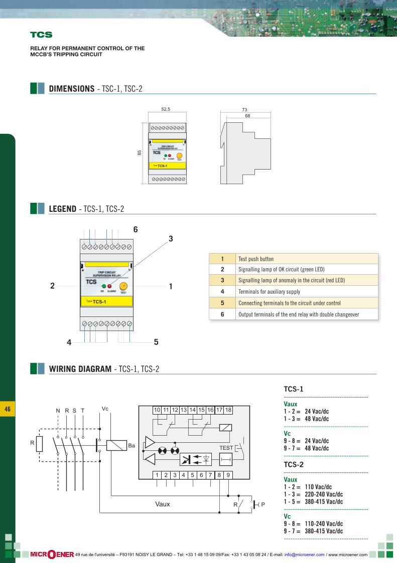
46
LEGEND - TCS-1, TCS-2
DIMENSIONS - TSC-1, TSC-2
WIRING DIAGRAM - TCS-1, TCS-2
TCS
RELAY FOR PERMANENT CONTROL OF THE MCCB’S TRIPPING CIRCUIT
TCS-1--------------------------------------Vaux1 - 2 = 24 Vac/dc1 - 3 = 48 Vac/dc--------------------------------------Vc9 - 8 = 24 Vac/dc9 - 7 = 48 Vac/dc--------------------------------------TCS-2--------------------------------------Vaux1 - 2 = 110 Vac/dc1 - 3 = 220-240 Vac/dc1 - 5 = 380-415 Vac/dc--------------------------------------Vc9 - 8 = 110-240 Vac/dc9 - 7 = 380-415 Vac/dc--------------------------------------
1 Test push button
2 Signalling lamp of OK circuit (green LED)
3 Signalling lamp of anomaly in the circuit (red LED)
4 Terminals for auxiliary supply
5 Connecting terminals to the circuit under control
6 Output terminals of the end relay with double changeover
TCS-1Type
1
36
5
2
4
TCS-3 TCS-4TCS-1 TCS-2
Vaux P
N R
R
S T Vc
Ba TEST
13 14 1510 11 12 16 17 18
4 5 61 2 3 7 8 9
Vaux PRR
N R
R
S T Vc
Ba TEST
12 118 7 6 10
41 2 3 13 14 15
TCS-3 TCS-4TCS-1 TCS-2
96
96 9096
5618
20
92
92
r.3
OK ALARM
Trip Circuit Supervision RelayTCS
TEST
contrel
7368
52,5
85ELR-3EELR-ELR-ELR-EEEELELLRLLLLLRRRRRRRRRRR-ELR-ELR-ELREELR-ELRELRELRLR-LR-LLRLR-LLRLRLRRRRRELREELRELRELRELRLR-LLRLR-LLR-ELRLRREEEELRLRLRLLLLLRELRLRRELRRELEEEEELRLR-LLRELRRELRLRELRRLR-EEELREELRELRRRREELR-LELRLRRELRRLLLLR-RR-RRELRELLRELRRRR---EELLRRRELRREEELRR-R---EELLRRRRRELLLLLLRRRELLRRRLRREELRLRREELELLRRRRRRELR 3E3E3E3333333E3EE3EE3E3E3E3333E33E3E3E3EEEE3EEE3E33E3E33E3E3E3EE3EE3333E3333E333EE3E3E3E33E3E3E33E33E3EEEEEEEE333333EEEEE3E3333EE3E3333EEE3333EEE3333EE3EEEEE3333333E3333333E3EEE333333EEEEE333EE333EE3333333EEEEEEEEE3333
TCS-1Type
/ www.microener.com 49 rue de l'université – F93191 NOISY LE GRAND – Tel: +33 1 48 15 09 09/Fax: +33 1 43 05 08 24 / E-mail: [email protected]
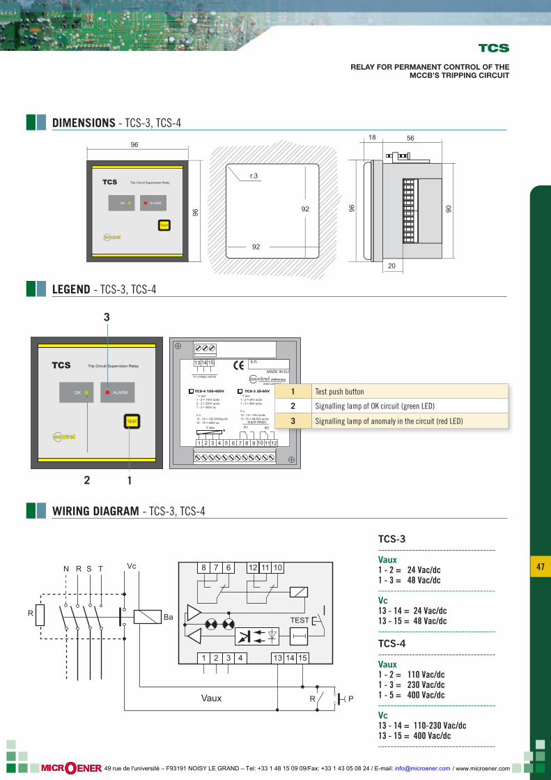
47 47
OK ALARM
Trip Circuit Supervision RelayTCS
TEST
contrel1 43 5 6 7 8 9
V aux.
* V aux:1 - 2 =
V ac/dc1 - 3 = 400V ac
V c13 - 14
110V ac/dc2 - 3 = 230
:= 100-230Vac/dc
13 - 15 = 400V ac
* V aux:1 - 2 = 24V ac/dc1 - 3 = 48V ac/dc
V c:13 - 14 = 24V ac/dc13 -15 = 48-60V ac/dc
*
13 14 15 s.n.
R1ouput relays
Vc voltage controlMADE IN EU
elettronicawww.contrel.it
TCS-4 100-400V TCS-3 20-60V
2 10 11 12
R2
LEGEND - TCS-3, TCS-4
DIMENSIONS - TCS-3, TCS-4
WIRING DIAGRAM - TCS-3, TCS-4
TCS
RELAY FOR PERMANENT CONTROL OF THE MCCB’S TRIPPING CIRCUIT
TCS-3--------------------------------------Vaux1 - 2 = 24 Vac/dc1 - 3 = 48 Vac/dc--------------------------------------Vc13 - 14 = 24 Vac/dc13 - 15 = 48 Vac/dc--------------------------------------TCS-4--------------------------------------Vaux1 - 2 = 110 Vac/dc1 - 3 = 230 Vac/dc1 - 5 = 400 Vac/dc--------------------------------------Vc13 - 14 = 110-230 Vac/dc13 - 15 = 400 Vac/dc--------------------------------------
1 Test push button
2 Signalling lamp of OK circuit (green LED)
3 Signalling lamp of anomaly in the circuit (red LED)
3
1
TCS-3 TCS-4TCS-1 TCS-2
Vaux P
N R
R
S T Vc
Ba TEST
13 14 1510 11 12 16 17 18
4 5 61 2 3 7 8 9
Vaux PRR
N R
R
S T Vc
Ba TEST
12 118 7 6 10
41 2 3 13 14 15
2
TCS-3 TCS-4TCS-1 TCS-2
96
96 9096
5618
20
92
92
r.3
OK ALARM
Trip Circuit Supervision RelayTCS
TEST
contrel
7368
52,5
85
ELR-3EELR-ELR-ELR-EEEELELLRLLLLLRRRRRRRRRRR-ELR-ELR-ELREELR-ELRELRELRLR-LR-LLRLR-LLRLRLRRRRRELREELRELRELRELRLR-LLRLR-LLR-ELRLRREEEELRLRLRLLLLLRELRLRRELRRELEEEEELRLR-LLRELRRELRLRELRRLR-EEELREELRELRRRREELR-LELRLRRELRRLLLLR-RR-RRELRELLRELRRRR---EELLRRRELRREEELRR-R---EELLRRRRRELLLLLLRRRELLRRRLRREELRLRREELELLRRRRRRELR 3E3E3E3333333E3EE3EE3E3E3E3333E33E3E3E3EEEE3EEE3E33E3E33E3E3E3EE3EE3333E3333E333EE3E3E3E33E3E3E33E33E3EEEEEEEE333333EEEEE3E3333EE3E3333EEE3333EEE3333EE3EEEEE3333333E3333333E3EEE333333EEEEE333EE333EE3333333EEEEEEEEE3333
TCS-1Type
/ www.microener.com 49 rue de l'université – F93191 NOISY LE GRAND – Tel: +33 1 48 15 09 09/Fax: +33 1 43 05 08 24 / E-mail: [email protected]
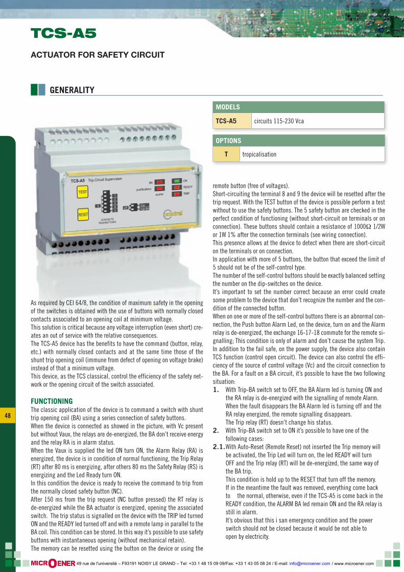
48
As required by CEI 64/8, the condition of maximum safety in the opening of the switches is obtained with the use of buttons with normally closed contacts associated to an opening coil at minimum voltage. This solution is critical because any voltage interruption (even short) cre-ates an out of service with the relative consequences.The TCS-A5 device has the benefits to have the command (button, relay, etc.) with normally closed contacts and at the same time those of the shunt trip opening coil (immune from defect of opening on voltage brake) instead of that a minimum voltage.This device, as the TCS classical, control the efficiency of the safety net-work or the opening circuit of the switch associated.
FUNCTIONINGThe classic application of the device is to command a switch with shunt trip opening coil (BA) using a series connection of safety buttons.When the device is connected as showed in the picture, with Vc present but without Vaux, the relays are de-energized, the BA don’t receive energy and the relay RA is in alarm status.When the Vaux is supplied the led ON turn ON, the Alarm Relay (RA) is energized, the device is in condition of normal functioning, the Trip Relay (RT) after 80 ms is energizing, after others 80 ms the Safety Relay (RS) is energizing and the Led Ready turn ON.In this condition the device is ready to receive the command to trip from the normally closed safety button (NC).After 150 ms from the trip request (NC button pressed) the RT relay is de-energized while the BA actuator is energized, opening the associated switch. The trip status is signalled on the device with the TRIP led turned ON and the READY led turned off and with a remote lamp in parallel to the BA coil. This condition can be stored. In this way it’s possible to use safety buttons with instantaneous opening (without mechanical retain).The memory can be resetted using the button on the device or using the
remote button (free of voltages).Short-circuiting the terminal 8 and 9 the device will be resetted after the trip request. With the TEST button of the device is possible perform a test without to use the safety buttons. The 5 safety button are checked in the perfect condition of functioning (without short-circuit on terminals or on connection). These buttons should contain a resistance of 1000Ω 1/2W or 1W 1% after the connection terminals (see wiring connection).This presence allows at the device to detect when there are short-circuit on the terminals or on connection.In application with more of 5 buttons, the button that exceed the limit of 5 should not be of the self-control type.The number of the self-control buttons should be exactly balanced setting the number on the dip-switches on the device.It’s important to set the number correct because an error could create some problem to the device that don’t recognize the number and the con-dition of the connected button.When on one or more of the self-control buttons there is an abnormal con-nection, the Push button Alarm Led, on the device, turn on and the Alarm relay is de-energized, the exchange 16-17-18 commute for the remote si-gnalling; This condition is only of alarm and don’t cause the system Trip.In addition to the fail safe, on the power supply, the device also contain TCS function (control open circuit). The device can also control the effi-ciency of the source of control voltage (Vc) and the circuit connection to the BA. For a fault on a BA circuit, it’s possible to have the two following situation:1. With Trip-BA switch set to OFF, the BA Alarm led is turning ON and the RA relay is de-energized with the signalling of remote Alarm. When the fault disappears the BA Alarm led is turning off and the RA relay energized, the remote signalling disappears. The Trip relay (RT) doesn’t change his status.2. With Trip-BA switch set to ON it’s possible to have one of the following cases:2.1. With Auto-Reset (Remote Reset) not inserted the Trip memory will be activated, the Trip Led will turn on, the led READY will turn OFF and the Trip relay (RT) will be de-energized, the same way of the BA trip. This condition is hold up to the RESET that turn off the memory. If in the meantime the fault was removed, everything come back to the normal, otherwise, even if the TCS-A5 is come back in the READY condition, the ALARM BA led remain ON and the RA relay is still in alarm. It’s obvious that this i san emergency condition and the power switch should not be closed because it would be not able to open by electricity.
GENERALITY
MODELS
TCS-A5 circuits 115-230 Vca
TCS-A5ACTUATOR FOR SAFETY CIRCUIT
OPTIONS
T tropicalisation
/ www.microener.com 49 rue de l'université – F93191 NOISY LE GRAND – Tel: +33 1 48 15 09 09/Fax: +33 1 43 05 08 24 / E-mail: [email protected]
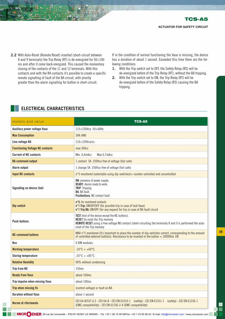
49 49
2.2 With Auto-Reset (Remote Reset) inserted (short-circuit between 8 and 9 terminals) the Trip Relay (RT) is de-energized for 50÷100 ms and after it come back energized. This caused the momentary closing of the contacts of the 11 and 12 terminals. With this contacts and with the RA contacts it’s possible to create a specific remote signalling of fault of the BA circuit, with priority greater than the alarm signalling for button in short-circuit.
If in the condition of normal functioning the Vaux is missing, the device has a duration of about 1 second. Exceeded this time there are the fol-lowing conditions:1. With the Trip switch set to OFF, the Safety Relay (RS) will be de-energized before of the Trip Relay (RT), without the BA tripping.2. With the Trip switch set to ON, the Trip Relay (RT) will be de-energized before of the Safety Relay (RS) causing the BA tripping.
ELECTRICAL CHARACTERISTICS
TCS-A5
ACTUATOR FOR SAFETY CIRCUIT
mode ls and va lue TCS-A5
Auxiliary power voltage Vaux 115÷230Vca 50÷60Hz
Max Consumption 5VA (4W)
Line voltage BA 110÷230Vca/cc
Functioning Voltage NC contacts max 30Vcc
Current of NC contacts Min. 0,4mAcc Max 0,7mAcc
BA command output 1 contact 5A 250Vca free of voltage (fail safe)
Alarm output 1 change 5A 250Vca free of voltage (fail safe)
Input NC contacts n°5 monitored (selectable using dip-switches)+ number unlimited and uncontrolled
Signalling on device (led)
ON: presence of power supply.READY: device ready to work.TRIP: Tripping.BA: BA fault.Pushbuttons: NC contact fault
Dip-switch n°5: for monitored contactsn°1 Trip: ON/OFFOFF (for possible trip in case of lack Vaux)n°1 Trip BA: ON/OFF (for any request for trip in case of BA fault circuit
Push-buttons
TEST (test of the device except the NC buttons).RESET (to reset the Trip memoryREMOTE RESET using a free voltage NO contact (short-circuiting the terminals 8 and 9 is performed the auto-reset of the Trip memory
NC command buttons MAX n°5 monitored (it’s important to place the number of dip-switches correct, corresponding to the amount of controlled external buttons). Resistance to be inserted in the button = 1000Ohm 1W.
Box 6 DIN modules
Working temperature -10°C ÷ +60°C.
Storing temperature -25°C ÷ +85°C
Relative Humidity 90% without condensing
Trip from NC 150ms
Ready from Vaux about 160ms
Trip impulse when missing Vaux about 100ms
Trip when missing Vc (control voltage) or fault on BA
Duration without Vaux about 1 second
Norme di riferimento CEI 64-8/537.4.3 - CEI 64-8 - CEI EN 61010-1 (safety) - CEI EN 61551-1 (safety) - CEI EN 61236-1 (EMC compatibility) - CEI EN 61236-2-4 (EMC compatibility)
/ www.microener.com 49 rue de l'université – F93191 NOISY LE GRAND – Tel: +33 1 48 15 09 09/Fax: +33 1 43 05 08 24 / E-mail: [email protected]
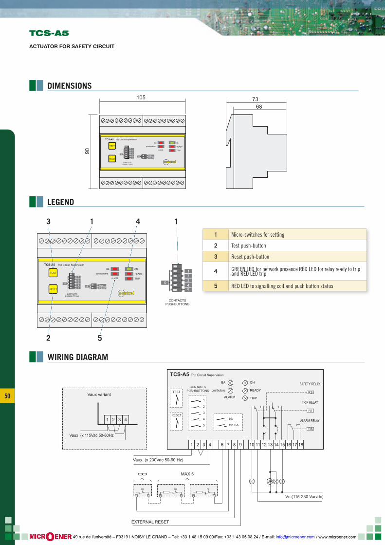
50
TEST
RESET
RESET
I (A)Δ
t (sec)ON
TRIP
TRIPALARM
A
M
0,4+
tx10
0,4+
tx1
IΔx1 x10
x0,1
IΔ
contrel 0,25
0,02
0,5
0,1
1
0,2
1,5
0,3
2
0,4
2,5
0,5
ELRD-L2m
TEST
RESEToff
CONTACTSPUSHBUTTONS
trip-BAtrip
345
21
ALARM
Trip Circuit SupervisionTCS-A5
0
ON
READY
TRIP
BA
pushbuttons
contrel
105
90
7368
TCS-A5
ACTUATOR FOR SAFETY CIRCUIT
LEGEND
DIMENSIONS
WIRING DIAGRAM
TEST
RESET
RESET
I (A)Δ
t (sec)ON
TRIP
TRIPALARM
A
M
0,4+
tx10
0,4+
tx1
IΔx1 x10
x0,1
IΔ
contrel 0,25
0,02
0,5
0,1
1
0,2
1,5
0,3
2
0,4
2,5
0,5
ELRD-L2m
TEST
RESEToff
CONTACTSPUSHBUTTONS
trip-BAtrip
345
21
ALARM
Trip Circuit SupervisionTCS-A5
0
ON
READY
TRIP
BA
pushbuttons
contrelCONTACTS
PUSHBUTTONS
345
21
0
1 143
2
1 Micro-switches for setting
2 Test push-button
3 Reset push-button
4 GREEN LED for network presence RED LED for relay ready to trip and RED LED trip
5 RED LED to signalling coil and push button status
5
TCS-A5 Trip Circuit Supervision
Vaux (x 230Vac 50-60 Hz)
Vaux (x 115Vac 50-60Hz
Vaux variant
Vc (115-230 Vac/dc)
MAX 5
EXTERNAL RESET
1
1
2 3 4
1 2 3 4
ALARM
ON
READY
TRIP
BACONTACTS
PUSHBUTTONSTEST
RESET
pushbuttons
6 7 8 9 10
BA
11 12 13 14 15 16 17 18
ALARM RELAY
TRIP RELAY
SAFETY RELAY
2
3
4
5
trip
trip BA
RS
RT
RA
/ www.microener.com 49 rue de l'université – F93191 NOISY LE GRAND – Tel: +33 1 48 15 09 09/Fax: +33 1 43 05 08 24 / E-mail: [email protected]
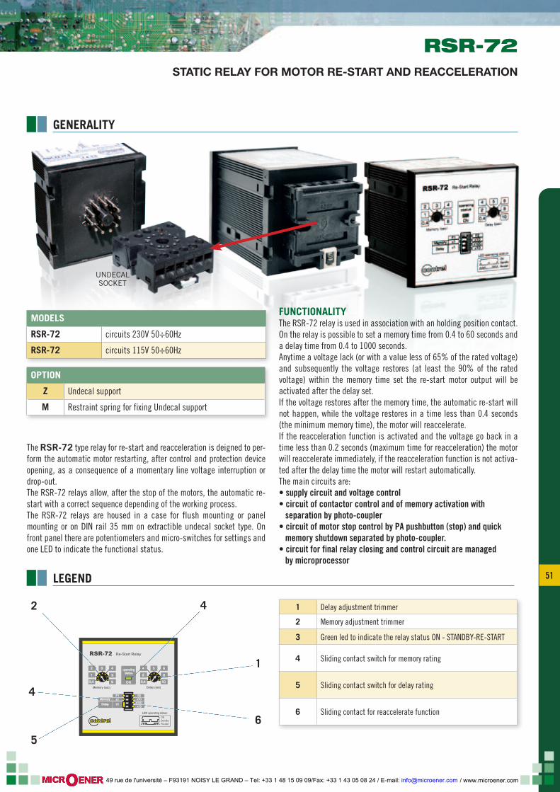
51 51
ON
Re-Start Relay
x100x1
F1
Delay (sec)Memory (sec)
4
5
6
operatingstatus
F2x1 x10
x10
Memory
Delay
RSR-72
contrel
0,4
1
2 3 6
0,4
2
4 5
8
10
ONStandbyRe-start
LED operating status:
GENERALITY
LEGEND
1 Delay adjustment trimmer
2 Memory adjustment trimmer
3 Green led to indicate the relay status ON - STANDBY-RE-START
4 Sliding contact switch for memory rating
5 Sliding contact switch for delay rating
6 Sliding contact for reaccelerate function6
5
2
4
4
1
The RSR-72 type relay for re-start and reacceleration is deigned to per-form the automatic motor restarting, after control and protection device opening, as a consequence of a momentary line voltage interruption or drop-out.The RSR-72 relays allow, after the stop of the motors, the automatic re-start with a correct sequence depending of the working process.The RSR-72 relays are housed in a case for flush mounting or panel mounting or on DIN rail 35 mm on extractible undecal socket type. On front panel there are potentiometers and micro-switches for settings and one LED to indicate the functional status.
FUNCTIONALITYThe RSR-72 relay is used in association with an holding position contact. On the relay is possible to set a memory time from 0.4 to 60 seconds and a delay time from 0.4 to 1000 seconds.Anytime a voltage lack (or with a value less of 65% of the rated voltage) and subsequently the voltage restores (at least the 90% of the rated voltage) within the memory time set the re-start motor output will be activated after the delay set.If the voltage restores after the memory time, the automatic re-start will not happen, while the voltage restores in a time less than 0.4 seconds (the minimum memory time), the motor will reaccelerate.If the reacceleration function is activated and the voltage go back in a time less than 0.2 seconds (maximum time for reacceleration) the motor will reaccelerate immediately, if the reacceleration function is not activa-ted after the delay time the motor will restart automatically.The main circuits are:• supply circuit and voltage control• circuit of contactor control and of memory activation with separation by photo-coupler• circuit of motor stop control by PA pushbutton (stop) and quick memory shutdown separated by photo-coupler.• circuit for final relay closing and control circuit are managed by microprocessor
UNDECALSOCKET
RSR-72STATIC RELAY FOR MOTOR RE-START AND REACCELERATION
OPTION
Z Undecal support
M Restraint spring for fixing Undecal support
MODELS
RSR-72 circuits 230V 50÷60Hz
RSR-72 circuits 115V 50÷60Hz
/ www.microener.com 49 rue de l'université – F93191 NOISY LE GRAND – Tel: +33 1 48 15 09 09/Fax: +33 1 43 05 08 24 / E-mail: [email protected]
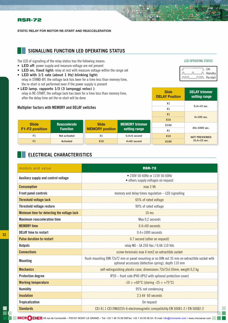
52
The LED of signalling of the relay status has the following means:• LEDoff: power supply and measure voltage are not present• LEDon,fixedlight: relay at rest with measure voltage within the range set• LEDwith1/1rate(about1Hz)blinkinglight: relay in STAND-BY, the voltage lack has been for a time less than memory time, the re-start is not performed even if the power supply is present•LEDlamp.rapporto1/3(3lampeggiveloci): relay in RE-START, the voltage lack has been for a time less than memory time, after the delay time set the re-start will be done
Multiplier factors with MEMORY and DELAY switches
ELECTRICAL CHARACTERISTICS
SIGNALLING FUNCTION LED OPERATING STATUS
RSR-72
STATIC RELAY FOR MOTOR RE-START AND REACCELERATION
mode ls and va lue RSR-72
Auxiliary supply and control voltage • 230V 50-60Hz or 115V 50-60Hz• others supply voltages on request
Consumption max 3 VA
Front panel controls memory and delay times regulation – LED signalling
Threshold voltage lack 65% of rated voltage
Threshold voltage restore 90% of rated voltage
Minimum time for detecting the voltage lack 10 ms
Maximum reacceleration time Max 0,2 seconds
MEMORY time 0.4÷60 seconds
DELAY time to restart 0.4÷1000 seconds
Pulse duration to restart 0.7 second (other on request)
Outputs relay NO - 5A 250 Vac / 0,4A 110 Vdc
Connections screw terminals max 4 mm2 on extractible socket
Mounting flush mounting DIN 72x72 mm or panel mounting or on DIN rail 35 mm on extractible socket with optional accessory (detection spring), depth 110 mm
Mechanics self-extinguishing plastic case, dimensions 72x72x110mm, weight 0,2 kg
Protection degree IP20 – front side IP40 (IP52 with optional protection cover)
Working temperature -10 ÷ +60°C (storing -25 ÷ +75°C)
Humidity 95% not condensing
Insulation 2,5 kV 60 seconds
Tropicalization On request
Standards CEI 41.1 CEI EN60255-6 electromagnetic compatibility EN 50081-2 / EN 50082-2
Slide F1-F2 position
Reaccelerate Function
F1 Not activated
F1 Activated
Slide MEMORY position
MEMORY trimmer setting range
X1 0,4÷6 second
X10 4÷60 second
Slide DELAY Position
DELAY trimmer setting range
X10,4÷10 sec.
X1
X14÷100 sec.
X10
X10040÷1000 sec.
X1
X10 NOT PREVIEWED (0,4÷10 sec.X100
LED OPERATING STATUS
/ www.microener.com 49 rue de l'université – F93191 NOISY LE GRAND – Tel: +33 1 48 15 09 09/Fax: +33 1 43 05 08 24 / E-mail: [email protected]
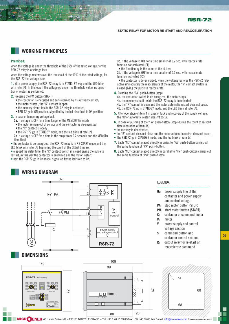
53 53
RSR-72
STATIC RELAY FOR MOTOR RE-START AND REACCELERATION
WIRING DIAGRAM
WORKING PRINCIPLES
Premised: when the voltage is under the threshold of the 65% of the rated voltage, for the RSR-72 relay is a voltage lackwhen the voltage restores over the threshold of the 90% of the rated voltage, for the RSR-72 the voltage is ok1. With power supply, the RSR-72 relay is in STAND-BY way and the LED blink with rate 1/1. In this way if the voltage go under the threshold value, no opera-tion of restart is performed.2. Pressing the PM button (START) • the contactor is energized and self-retained by its auxiliary contact; • the motor starts , the “R” contact is open • the memory circuit inside the RSR-72 relay is activated; • RSR 72 go in ON position, signalled by the led also fixed in ON position.3. In case of temporary voltage lack: 3a. if voltage is OFF for a time longer of the MEMORY time set: • the motor remain out of service and the contactor is de-energized; • the “R” contact is open; • the RSR 72 go in STANDBY mode, and the led blink at rate 1/1. 3b. if voltage is OFF for a time in the range from 0.2 seconds and the MEMORY time fixed:• the contactor is de-energized, the RSR-72 relay is in RE-START mode and the LED blink with rate 1/3 beginning the count of the DELAY time set;• elapsed the delay time, the “R” contact switch in closed giving the pulse to restart, in this way the contactor is energized and the motor restart;• next the RSR 72 go in ON mode, signalled by the led fixed to ON;
3c. if the voltage is OFF for a time smaller of 0.2 sec. with reaccelerate function not activated (F1) • the functioning is the same of the b) item 3d. if the voltage is OFF for a time smaller of 0.2 sec. with reaccelerate function activated (F2) • the contactor is de-energized, when the voltage restores the RSR-72 relay active immediately the reaccelerate of the motor, the “R” contact switch in closed giving the pulse to reaccelerate.4. Pressing the “PA” push-button (stop) 4a. the contactor-switch is de-energized, the motor stops; 4b. the memory circuit inside the RSR-72 relay is deactivated; 4c. the “R” contact is open and the motor automatic restart does not occur. 4d. the RSR-72 go in STANDBY mode, and the LED blink at rate 1/1.5. After operation of item 4 in case of lack and recovery of the supply voltage, the motor automatic restart doesn’t occur.6. In case of pushing of the “PA” push-button (stop) during the count of re-start time (operation of item 3b)• the memory is deactivated;• the “R” contact does not close and the motor automatic restart does not occur;• the RSR 72 go in STANDBY mode, and the led blink at rate 1/1.7. Each “NO” contact placed directly in series to “PA” push-button carries out the same function of “PA” push-button.8. Each “NO” contact placed directly in parallel to “PM” push-button carries out the same function of “PM” push-button
Uc
power supplyand voltage control
cpu and
control
PA
PMR
1
2
9
11
6
4
M RSR-72
V
S
C
DIMENSIONS
72
72
109
67
ON
Re-Start Relay
x100x1
F1
Delay (sec)Memory (sec)
4
5
6
operatingstatus
F2x1 x10
x10
Memory
Delay
RSR-72
contrel
0,4
1
2 3 6
0,4
2
4 5
8
10
ONStandbyRe-start
LED operating status:
80 20
89
68
68
r.3
LEGENDA------------------------------------------Uc: power supply line of the contactor and power supply and control voltagePA: stop motor button (STOP)PM: start motor button (START)C: contactor of command motorM: motorV: power supply and control voltage sectionS: command button and contactor control sectionR: output relay for re-start an reaccelerate command
/ www.microener.com 49 rue de l'université – F93191 NOISY LE GRAND – Tel: +33 1 48 15 09 09/Fax: +33 1 43 05 08 24 / E-mail: [email protected]
According to the copyright and the civil
law,the reproduction of this catalogue, or
any part of this one, by electronic, mecha-
nical methods, by means of photocopies,
microfilms, recordings or other, is perem-
ptorily forbidden. Rights are reserved for
all countries.
Drawings, specifications and reference
numbers may be modified and changed.
CONTREL s.r.l reserves itself the right, to
make changes for technical or quality
improvements, without any notice.
April 2009
www.contrel.it
e le t t ron i ca
ISO 9001:20009105-C035
EARTH LEAKAGE RELAY
STATIC RELAY FOR MOTOR RE-START
AND REACCELERATION
RELAY FOR PERMANENT CONTROLOF THE MCCB’S TRIPPING CIRCUIT
AND ACTUATOR FOR SAFETY CIRCUITS
© C
ontr
el e
lettr
onic
a -
tutti
i di
ritti
ris
erva
ti -
finito
di s
tam
pare
Apr
ile 2
009
conc
ept
| des
ign
| pho
to |
ww
w.n
eod
os.it
/ www.microener.com 49 rue de l'université – F93191 NOISY LE GRAND – Tel: +33 1 48 15 09 09/Fax: +33 1 43 05 08 24 / E-mail: [email protected]


![VWHPV %LR (QKDQFHG ELR /HQH %LRSODVWLF …€¦ · elr /hqh lv d 6lhuud 5hvlqv 0dvwhuedwfk sro\phu dgglwlyh elr frqfhqwudwh irupxodwhg iru hq]\ph frqvxpswlrq 06, elr /hqh zkhq dgghg](https://img.pdfslide.us/doc/110x75/6008f2b1a20bcb0a8f117777/vwhpv-lr-qkdqfhg-elr-hqh-lrsodvwlf-elr-hqh-lv-d-6lhuud-5hvlqv-0dvwhuedwfk-srophu.jpg)