Embed Size (px)
Citation preview
EARTH INTEGRATION FOR COOLING
SEMINAR PROCEEDINGS
Internal Passive and Hybrid Cooling Conference
Miami Beach, Florida, USA
9th November 1981
Seminar Co-ordinator: Lester Boyer Oklahoma State University Proceedings Editors: Lester Boyer Walter Grondzik Oklahoma State University Typing and Graphics: Julia Dowlen Tim Johnston
Prepared by: Centre for Natural Energy Design, School of Architecture Division of Engineering, Oklahoma State University, Stillwater, Oklahoma
TECHNICAL SEMINAR
EARTH INTEGRATION FOR COOLING
Monday, 9 November 1981, Final Program International Passive and Hybrid Cooling Conference
Miami Beach, Florida, USA
Presented by:
Passive Division of the American Section International Solar Energy Society
Sponsored by:
Office of Solar Applications for Buildings, Passive & Hybrid Division, US Dept of Energy
University of Miami,
School of Engineering and Architecture Coral Cables, Florida
Prepared by: Centre for Natural Energy Design, School of Architecture Division of Engineering, Oklahoma State University, Stillwater, Oklahoma
LIST OF CONTENTS
EARTH INTEGRATION FOR COOLING
Monday 9 November 8.00 am – 12.00 Technical Seminar 8.0 - Introduction: Earth Shelter Phenomenon 8.20 Lester Boyer, Oklahoma State University, Oklahoma 8.20 Vernacular Earth Shelters Throughout the World 8.45 Arthur Bowen, University of Miami, Florida 8.45 Earth Temperature Modification 9.10 Baruch Givoni, Institute for Desert Research, Israel 8.15 Earth Integration Techniques 9.40 Steven Szokolay, University of Queensland, Australia 9.45 Short Break 10.00 10.0 Vegetation Effects on Earth Cooling Potential 10.25 Sydney Baggs, Univ of New South Wales, Australia 10.30 Building Design for Earth Cooling 10.55 Walter Grondzik, Oklahoma State University, Oklahoma 11.0 Energy and Habitability Aspects 11.25 Lester Boyer, Oklahoma State University, Oklahoma 11.30 Indirect Earth Cooling Techniques 12.0 James Akridge, Georgia Institute of Technology, Georgia
EARTH SHELTER PHENOMENON
Lester L Boyer School of Architecture Division of Engineering
Oklahoma State University Stillwater, Oklahoma 74078, USA
EARTH SHELTER PHENOMENON
Lester L Boyer School of Architecture, Division of Engineering
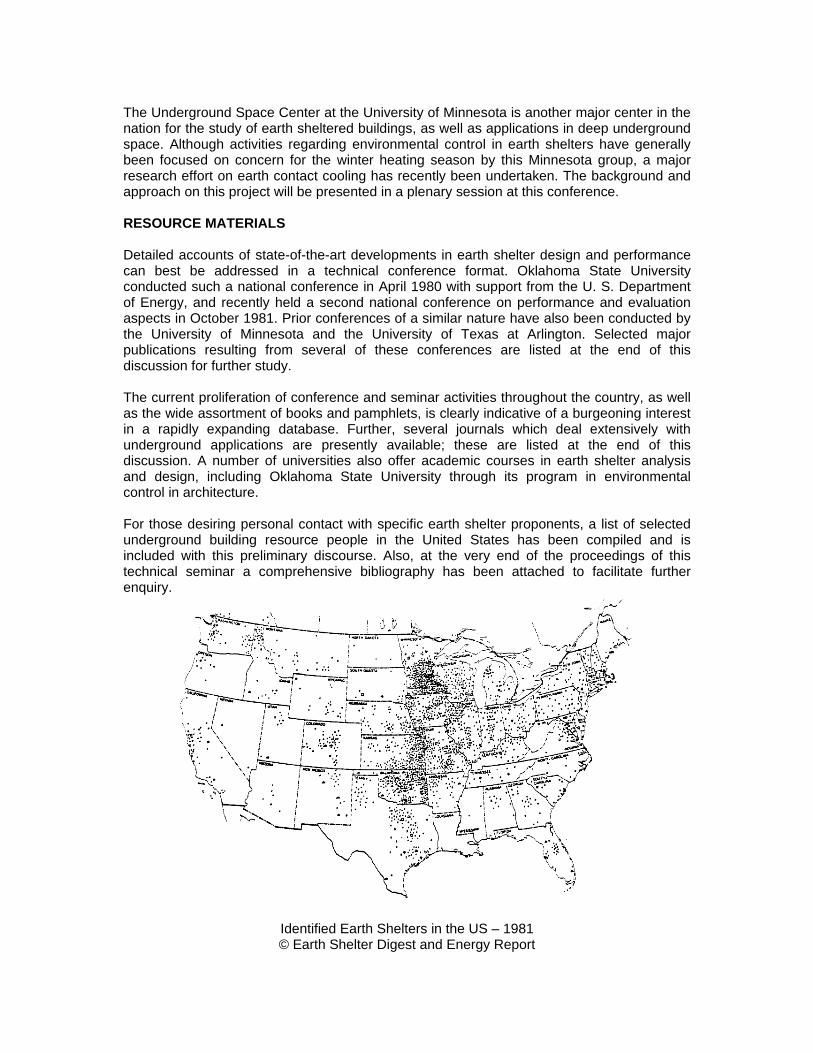
Oklahoma State University Stillwater, Oklahoma 74078, U. S. A. INTRODUCTION Both national and international attention has recently been focused on earth sheltered construction as an emerging energy alternative. This is especially true for the High Plains region of the central United States. Traditionally, inhabitants of this region have been sensitized to the need for windstorm protection. However, the dramatic potentials for energy savings have served as a strong secondary inducement to the burgeoning construction activity in what is now viewed as a contemporary dwelling concept. The number of verified earth shelter projects as of June 1981 is shown graphically on the accompanying U. S. map prepared by editors of the Earth Shelter Digest magazine. The actual verified count has been placed at 2,250. However, since undoubtedly all projects have not been thus far reported, it is reasonable to expect that the actual total is perhaps on the order of 3,000 to 5,000 constructed projects. A shifting emphasis toward passive cooling has been developing with regard to the energy incentive for building earth shelters. Most of the third world developing countries are in the hot regions of the earth. A keen interest in earth cooling has been growing in these areas. In fact, the U.S. State Department conducted a briefing early this year to examine the potential for encouragement and education on the subject of earth shelters for emerging nations. Also, the author recently accepted personal invitations to collaborate in earth shelter education and research in Saudi Arabia and Australia. According to Prof. John Yellott, Technical Chairman of this International Passive Cooling Conference, the topic for which most technical papers were offered was in the area of earth integration for cooling. Oklahoma State University has been responsible for developing this present 4-hour pre-conference technical seminar, and further technical paper sessions cover a three-day period. STUDY CENTERS Oklahoma State University has become a leading center in the nation for the study of earth sheltered buildings, especially with regard to warm climate design. More than two dozen technical papers have been published by staff within the past three years, and two national technical conferences have been conducted to date. Intensive short courses have been conducted by Architectural Extension throughout the country since early 1977. Programs have been conducted in locations such as Chicago, Denver, Boston, Virginia, San Francisco, Phoenix, Dallas, and of course Oklahoma. These programs have been approved nationally by the American Institute of Architects for continuing education units (CEU's).
Externally funded earth shelter research studies thus far conducted at Oklahoma State University have focused on detailed multi-state occupant surveys, instrumented field monitoring, energy and habitability studies, interiors engineering, and input development for national information exchange networks. Also, Department of Energy Fact Sheets have recently been developed on daylighting, earth cooling, interior air quality, disaster mitigation, solar integration, and expansive clay soil concerns. A new Environmental Simulation Laboratory on the campus can be used to simulate earth shelter environment effects as well as other simulated mock-up conditions.
The Underground Space Center at the University of Minnesota is another major center in the nation for the study of earth sheltered buildings, as well as applications in deep underground space. Although activities regarding environmental control in earth shelters have generally been focused on concern for the winter heating season by this Minnesota group, a major research effort on earth contact cooling has recently been undertaken. The background and approach on this project will be presented in a plenary session at this conference. RESOURCE MATERIALS Detailed accounts of state-of-the-art developments in earth shelter design and performance can best be addressed in a technical conference format. Oklahoma State University conducted such a national conference in April 1980 with support from the U. S. Department of Energy, and recently held a second national conference on performance and evaluation aspects in October 1981. Prior conferences of a similar nature have also been conducted by the University of Minnesota and the University of Texas at Arlington. Selected major publications resulting from several of these conferences are listed at the end of this discussion for further study. The current proliferation of conference and seminar activities throughout the country, as well as the wide assortment of books and pamphlets, is clearly indicative of a burgeoning interest in a rapidly expanding database. Further, several journals which deal extensively with underground applications are presently available; these are listed at the end of this discussion. A number of universities also offer academic courses in earth shelter analysis and design, including Oklahoma State University through its program in environmental control in architecture. For those desiring personal contact with specific earth shelter proponents, a list of selected underground building resource people in the United States has been compiled and is included with this preliminary discourse. Also, at the very end of the proceedings of this technical seminar a comprehensive bibliography has been attached to facilitate further enquiry.
Identified Earth Shelters in the US – 1981 © Earth Shelter Digest and Energy Report
VERNACULAR EARTH SHELTERS THROUGHOUT THE WORLD1
Arthur Bowen School of Engineering and Architecture
University of Miami Coral Gables, Florida 33124, USA
INTRODUCTION Less than a decade has transpired since scientific interest has been aroused in earth contact habitations. However, one way or another, humans have lived in this way for five thousand years in many widely spread geographic locations, without knowledge of the existence of other similar underground shelter or settlements. This paper is intended to identify some of these notable historical developments. CLASSIFICATION OF EARTH-CONTACT STRUCTURES A review of global communities reveals seven categories of earth-contact shelter or settlement which emerge from two generic types:
(a) sack or (b) transit caves.
The seven categories may be identified as follows, and as shown in the first grouping of figures.
1. Subtract 2. Subtract and add 3. Cut, fill and sod 4. Earth berm and sod 5. Courtyard or patio 6. Deep well 7. Insula
EARLY BUILDINGS AND COMMUNITIES The earliest are found in Egypt, the Mediterranean, Asia Minor, India, China and France. Initially, these shelters were carved from hard rock to preserve the dead or provide a religious home for a deity. With the passage of time, many of these tombs and temples were discovered to provide a suitable preservative climate and were later occupied as dwellings. Today, several of these earlier excavations have been further subtracted and added to provide livable contemporary settlements. Egypt Three types of tombs – Mastabas, royal pyramid and rock-cut tombs. These are rare before the Middle Kingdom (Dynasties XI-XVII or 2130 to 1580 BC). Occasionally, rock-cut mortuary temples are associated with these tombes.
1 Excerpted from Proc. Earth Shelter Performance and Evaluation Conf. Conducted by Oklahoma State University, 1981.

Rock-cut Tombs 1. Tombs at Beni Hasan, numbering 39, belonged to a great provincial family. Eleventh
and Twelfth Dynasty (2130-1785 BC). Chamber behind a porticoed façade. Columned, vaulted, stuccoed and painted with scenes.
2. Tombs of the Kings, Thebes. Over 43 known tombs. Corridor types, in which stairs,
passages and chambers extend as much as 690 ft into the mountainside and up to 315 ft, below the valley floor. The sarcophagus lay in a terminal rock-columned hall, and the walls were elaborately painted with ceremonial funerary scenes. The most important tombs are Seti I, Rameses III, IV and IX. New Kingdom (Dynasties XVIII to XXX, 1580 to 332 BC).
Rock-cut Temples 1. The mortuary temple of Mentuhetep, Der el Bahari (2065 BC) is unique in that it is a
mortuary temple directly related to a corridor tomb. It is terraced in two main levels, at the base of steep cliffs.
2. The Great Temple, Abu-Simbel (c. 1301 BC). Protected by four seated colossi of
Rameses II, over 65 feet high, is the most impressive of its class. The façade is 119 feet high and 105 feet long. The main hall is 30 feet high. There are twelve additional chambers.
3. The small Temple, Abu-Simbel (c. 1301 BC). Built by Rameses II for his Queen
Nefertari and the goddess Hathor. The façade is 90 feet wide and 40 feet high, displaying six colossal statues 33 feet high, leads to a vestibule and hall 34 feet x 27 feet.
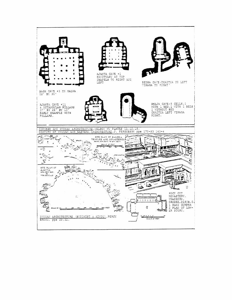
4. The rock-cut temple at Gerf Hosein (c. 1301 BC). Asia Minor In Cappadocia, Turkey, the Goreme Valley is dotted with thousands of “tuffa” cones that have been excavated into 365 churches and literally thousands of dwellings – single and multi-storey. The churches are Byzantine. Paul Lukas, an emissary of Louis XIV, writes –“I was overtaken by an incredible astonishment at the site of some ancient monuments the other side of the river (Kizil Irmak). Not even now can I think of them without being struck. Although I have traveled a good deal, I never have seen or heard of anything similar – pyramids in prodigious number and various height, each consisting of a single rock, hollowed out in a way to provide several apartments, one on top of the other, with beautiful entrance doors and large windows for the well-lighted rooms”. Today, thousands of these dwellings are still occupied - with additions and "modernization ". In Petra, Jordan, are over 750 rock-cut tombs. The tomb of El Khasne (c. 120 AD) is one of the most interesting. Facade is 65 feet high. Lower level is hexagonal, upper level circular surmounted by a conical roof and urn. India Brahmanical, Buddhist, Jaina. Rock-cut monasteries and temples probably number 1200 of which 300 are of Brahmanical or Jama origin. The remaining 900 are Buddhist. By far the majority are monasteries. As the purpose of these excavations were for everlasting preservation, they were invariably subtracted from hard basalt rock. The Brahmins produced temples, the Buddhist "chaityas" or worshipping places and "viharas" or monasteries, while
the Jains produced "bhikshugrihas", or dwellings for their recluses. Furthermore, there are outstanding rock-cut Jaina, Shiva, Vishnu and Brahman temples in several locations in west, central and south India. The "Khailasa" temple to Shiva, cave at Ellura, number 16, must be the eighth wonder of the world. It is the greatest work of art in a country that abounds in it! The most important rock-cut work in India is to be found at Ajanta, Elluria, Aurangabad, Elephanta, Kahheui, Bhaha, Karli, Nasik, Bagh, Kondane, Bedsa, Junnar, Udaigiri, Pitalkhora, Homas Rishi, Pune and Badami. Some of these are illustrated. Mention should be made here of the vast Hindu temples and later Buddhist communities constructed from massive stone that thermally modify the climate extremes experienced in India. TRADITIONAL CONTEMPORARY SETTLEMENTS Some of the ancient communities are still alive, exhibiting "improvements", such as in Cappadocia, Turkey. However, other contemporary settlements known to have started centuries ago are vibrant with life.
Examples include:
Guadix, Spain, where about 10,000 people dwell in an en tire village that is subtracted with extensions to enhance the beauty of the buildings with entrances, openings and chimneys, to provide good clean, well ventilated and lighted interiors, thermally agreeable in summer a.l1d winter. Other cave dwellings in Spain are at Almanzora in Andalusia and Galdar, Grand Canary.
Matmata, southern Tunisia, where a 7000 population presently lives in completely excavated dwellings clustered around deeply excavated wells varying in size from 20 feet deep and 40 feet wide to 30 feet deep and 200 feet across. There is a long, gentle slope connecting the floor of each well to the ground level and a cistern is located at the lowest level to trap con-densation and any slight rain, in a very arid climate exhibiting large seasonal and diurnal temperature shifts. The “crater” forms a trap for a katabatic action of cold night air, to provide summer cooling. It also prevents dust-storms from affecting the lower living area and acts as a community square. The village was used in the movie “Star Wars” to represent a settlement in the year 3000!
Provinces of Shensi, Shansi, Kansu and Honan, China. More than 10 million people live in loess excavated dwellings. In the Kansu earthquake of 1920 246.000 people perished. Loyang is a major settlement.
Belen de las Flores, Mexico City, Mexico. Cave dwellings rock-cut into seven tiered terraces. Some dwellings have one-storey extensions built out from the hill. One community faucet per terrace. electricity, television, doors, windows and interior paintings. About 1000 inhabitants. Rent free. Average depth 10 feet.
In many of the Aegean Islands, Greece, vibrant and attractive villages are found with earth-contact residences on one or several floors. Thera-Santorini provides a good example.
Wieliczka, Poland, is no ordinary salt mine. It is a community. Its 65 miles of tunnel go to a depth of 1000 feet. At one time, housed churches, shrines, railway, restaurants, sixteen ponds of clear water, dancing salon and an imaginative vertical transport system.

RECENT ACTIVITIES Recent work is predominantly found in the United States. This is the result of the impressive thermal and comfort conditions that are experienced by occupants. The work is well published in popular and professional journals. Considerable research is now underway and at an International Expert Group Meeting held in Miami, Florida, the following research and development recommendations were made in regard to earth-contact cooling. 1) meteorology data collection should be extended to include essential earth
composition information, such as, soil moisture, regional water content, subterranean temperature profiles.
2) determine the effects of soil composition, moisture content and ground cover on earth temperatures at various levels.
3) provide accurate subterranean data and profiles in presently inaccurate areas. such
as, coastal zones, lake and riverside. 4) assemble data achieved .into algorithms for regional dissemination through simple
computer programs. 5) determine the effects of surface evaporation on soil temperature profiles. 6) determine the effects of controlled added moisture on soil temperature profiles. 7) expand research into the use of winter air to modify summer soil temperatures
through earth heat exchangers. 8) existing data on heat exchange with the ground should be collected and augmented
with new performance data, for computer modelling and distribution of generic systems.
9) explore chemical alteration to the soil and the effects of electric fields.
10) develop regional guidelines for dehumidification, ventilation, daylighting, view, access, etc.
11) obtain experimental data on sod roof design, moisture percolation, drainage, etc.
Also, moisture removal from the interior. 12} identify and resolve structural concerns such as expansion and contraction of soils,
earthquakes and mechanical strength. BIBLIOGRAPHY Brown, Percy, Indian Architecture, 2 vols., D.B. Taraporevala and Sons, Bombay, India. Fergusson, James, History of Indian and Eastern Architecture, 2 vols., John Murray, London, 1876.
Fletcher, Banister, A History of Architecture on the Comparative Method, University of London, Athlone Press, 17th edition, 1961.
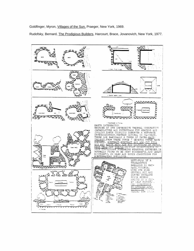
Goldfinger, Myron, Villages of the Sun, Praeger, New York, 1969.
Rudofsky, Bernard, The Prodigious Builders, Harcourt, Brace, Jovanovich, New York, 1977.
EARTH TEMPERATURE MODIFICATION1
Baruch Givoni
Institute for Desert Research Ben Gurian University Sede-Boqer Campus, Israel
INTRODUCTION The "natural", unmodified temperature of the ground is governed by two boundary conditions: the cyclic annual pattern of the surface temperature and the constant temperature at a depth of several meters. Over large homogeneous areas, the "depth" temperature equals the long-term annual average of the surface temperature. However, in any given small-scale area, the surface temperature may be affected by local factors, such as color (reflectivity, albedo), ground cover, etc. In addition, the annual pattern of precipitation (rain and snow), as well as large-scale regular irrigation, may introduce a bias, in favour of the surface temperatures prevailing either in summer or in winter, in determining the constant depth temperature. An earth integrated building disturbs and modifies the natural ground temperature and there is a constant thermal interaction between the interior of the building and the surrounding earth. NATURAL APPROACHES TO EARTH COOLING In places where the annual average temperature is above 18°C (64.4°P) cooling pf underground buildings, mainly in summer, may be required for human comfort. The earth temperature, even at a depth of 1-3 meters (3-10 it), is higher in summer than the annual average temperature and, in hot places, might be above the human comfort zone.
It should also be remembered that the average indoor temperature of an earth-integrated building is higher than the surrounding earth temperature, because of the heat generated internally by the indoor activities. Moreover, in summer the hot air which is introduced into the building for ventilation adds to the heat which has to be dissipated through the envelope into the surrounding earth. Airconditioning can, of course, always provide the required cooling, and the energy consumed will usually be less in an earth-integrated building than in similar above-ground buildings. However, in many hot climates, especially in desert regions. it is possible to provide natural "passive" cooling for earth integrated buildings more easily than to ordinary buildings. The basic strategy is to lower the temperature of the earth around and above the building well below the level typical for the given region, by lowering the surface temperature of the earth and/or by cooling the "deep" underground earth mass directly.
Several options are available for lowering the underground temperature in hot regions where the earth temperature in summer might be too hot from the viewpoint of human comfort in underground buildings. The various options can be divided into two complementary approaches:
a) Surface cooling, where the surface temperature of the earth above, and around the 1 Excerpted from presentation at: International Expert Group Meeting on Passive Cooling and Dehumidification, University of Miami, 1980.
building is lowered below its "natural" level, and consequently the temperature of the earth mass below the surface is lowered.
b) Direct cooling of a large mass of the sub-surface earth by increasing. Its cooling rate
in winter relative to the heating rate in summer. COOLING OF THE EARTH SURFACE The surface temperature of the earth in a given area is determined by the balance of several heat transfer modes:
a) absorption of solar energy during daytime;
b) heat loss upwards by long wave radiation to the sky; c) heat exchange by convection with the ambient air. Usually heat loss during daytime
and heat gain at night; d) heat loss by water evaporation from the surface. Modes (a) and (d) can be modified by design so that the energy balance results in a lower heat gain and/or greater heat loss. Consequently, the "modified" surface temperature of the "treated" area will be lower than that of neighboring g areas.
Eliminating Solar Heating of the Surface
The heating effect of solar radiation can be reduced or even eliminated by shading or changing the albedo (reflectivity) of the surface. However, in some cases the shading devices, e.g. trees or shrubs, also reduce the rate of radiative heat loss from the surface, so that only the net radiant exchange is effective. Experiments by Kusuda in Washington, D. C., have demonstrated that the average surface temperature of white-painted asphalt was lowered in midsummer by about 7°C (12.6°F) as compared with the surface of black asphalt (1). The average surface temperature of soil covered (and shaded) by long grass was lowered about 4°C (7. 2OF) as compared with the bare soil. The total effect of shading and (uncontrolled) evaporation was to lower the average surface temperature in midsummer by about 11°C (19.8°F). At a depth of 30 cm (1 ft) J the corresponding reductions in the soil temperature were still similar to those at the surface. Shading of the ground surface can also be provided by a layer of lightcolored pebbles or gravel, about 10-15 cm (4-6 in) thick (1). Solar radiation is intercepted and absorbed within about 2-3 cm (1 in) at the top of that layer, and the conduction of the heat down the layer of pebbles is rather low.
Cooling the Earth by Controlled Irrigation
Water evaporation from the ground can be very effective in lowering the earth's surface temperature. However, the actual quantitative effect depends on the circumstances under which the evaporation, and the watering producing it, take place. When sun-irradiated earth is watered, the surface temperature is sharply reduced, but heat is carried down with the water to heat up the sub-surface earth. As wet soil is darker than dry
soil, more solar energy is absorbed in, and less reflected away from, the surface. While a high rate of evaporation takes place from the warm surface, a significant part of it is consumed to overcome the heating effect of the absorbed solar energy. The net result of all these factors is a relatively low efficiency of the evaporation process in cooling the earth's mass. On the other hand, when irrigation takes place during the night and early morning hours the earth's surface is cooler than the "deep" ground. The irrigation water "carries the cold" downward, lowering the temperature of the sub-surface earth's mass. When a shaded area is irrigated, no evaporation is "wasted" to overcome the heating effect of solar energy, so that it is more effectively utilized in cooling t11e soil. Thus, the timing of irrigation and the shading conditions of the surface can change the effect of the watering on the heat flow between the surface and the depth of the ground and the cooling efficiency of the evaporation process. Experiments in the desert area of the Negev in Israel by Brown and Givoni (2J3J have shown that by shading the ground with a layer of pebbles (gravel), 12am (5 in) thick, and irrigation, it was possible to lower the earth temperature in midsummer, at a depth of 10 cm (4 in), by 9°C (16.2°F) as compared with "natural" desert soil of moderate albedo (light-colored loess soil). At a depth of 30 cm (1 ft), the reductions in the soil temperature were also similar in this study. At greater depth in the ground, the cooling effect of the lower surface temperature of areas of small sizes is reduced,' because of the heat flow towards the cooled soil from the warmer earth mass around it, and the unmodified ground constant temperature below it. The gravel layer serves a double function: firstly, it absorbs the solar energy above the soil surface, and dissipates it mostly into the ambient air, thus providing effective shading for the soil. Secondly, it enables water evaporation to cool the soil and not waste it to overcome solar energy which otherwise would be absorbed in the soil. The layer of pebbles also act during the daytime as an insulating layer between the ambient hot air and the cooler soil, while at night some cold air can sink down through the stones. It has also been demonstrated that irrigation during the day has actually raised the soil surface temperature, by carrying heat from the warm pebbles down to the soil. On the other hand, night-time and early-morning irrigation helped in cooling the soil surface.
Applications of the Surface-cooling Techniques
The results of the experiments of Brown and Givoni have demonstrated that it is possible to utilize the ground-surface cooling techniques either passively or actively for the cooling of earth-integrated buildings (3). The suitability of a passive cooling system based on surface cooling depends on the climate. In hot regions, where cooling is needed year round, the earth above and around the building can be cooled constantly by the combination of shading and evaporative cooling of the soil by a layer of gravel over the surface, or by vegetation cover. In this case, the temperature of the earth surrounding the building will be substantially lower than the "natural" soil in the area. The expected actual reduction in the earth's temperature under the cooled surface might range from about 4°C to 10°C (9-18°F) below the surrounding earth.
In a desert climate, it is possible to keep the soil dry during most of the winter, so as to
minimize the heat loss from the building. In summer the soil can be irrigated, and thus cooled evaporatively, when cooling is needed. In regions with a rainy summer and a dry winter, like the high Plateau of South Africa, earth-covered buildings with surface cooling may provide the optimal solution for passive heating and cooling. In regions with cold, rainy winters and hot summers, passive evaporative cooling in summer may not be appropriate, as the same cooling mechanism will cool the building mainly in winter. In such regions the building should be well insulated, and an active cooling system can utilize chilled earth around the building, by blowing air through embedded air-pipes. COOLING THE SUB-SURFACE SOIL The cooling effect produced at the earth's surface can propagate downwards by conduction, or be assisted by passive and/or active convection. It is also possible to change the relative rates of heat exchange between the surface and the earth mass below, so that in hot regions the rate of cooling of the subsurface earth mass in winter is faster than the rate of heating in summer. Increasing the rate of "cold" flow in winter into the depth of the ground relative to the rate of heat flow in summer can be achieved in several ways:
a) Utilizing the natural tendency of cold air to sink when it is above a layer of warmer air, and that of warm air to float over colder air.
b) Inducing forced convection (by wind or by mechanical means) into an underground layer in winter and stopping it in summer.
c) Combinations of these two methods. Forced convection of cold into the under-ground earth layer can be effected either by water or by air flow, depending on the materials of the layers around the building. In particular, it depends on whether the layers above the underground building are comprised of earth or of gravel (or pebbles). A common problem to all methods of winter cold storage in the earth around the building is that of reducing the protective efficiency of the earth in winter, when the cold is collected. The summer level of the underground temperature should be lowered without causing excessive cooling of the building in winter. In addition, some preheating of the ventilation air in winter may be desirable. It can be achieved by blowing the outdoor ventilation air through the earth, thus combining preheating of the ventilation air with cooling of the earth around the building, for long term cold storage. Underground Buildings covered by an Earth Layer In most earth-covered buildings, the ground area above the building will be utilized, e.g. for parks, gardens, greenhouses etc. In such cases of a shallow earth cover over the roof of the building, it would be undesirable to cool the top layer in winter, as this will increase the heating demand. However, the earth mass around the building at some distance from it can be cooled during the winter, to increase its coaling potential for the next summer. In order to cool the underground to a temperature below the natural equilibrium temperature, it would be necessary to bypass the resistance of the earth in winter. As an example, the following methods are suggested for enhancing the effect of winter cooling on the underground temperature around earth-covered buildings by air flow.
Air has several advantages over water as the medium for transporting winter Geld to the underground layers. Firstly, it enables transport of cold even when the outdoor temperature drops below freezing point. Secondly, with air flow through embedded "arteries” of rocks or ducts, it is possible to obtain a larger area of contact with the earth layer to be cooled than would be possible with water flow in pipes.
Horizontal Gravel Arteries Around the Earth-covered Building
The earth mass around the building and at some distance from it can be cooled in winter and protected from heating in summer by gravel "arteries" embedded in the soil at some depth, e.g., 1-2 meters (3-7 ft). Winter air can be introduced into these gravel arteries to cool the sub-soil. The air can flow either through the rocks or within perforated pipes within the gravel arteries. The earth's surface above that zone can be cooled in summer by the methods discussed above, so as to minimize the rate of heating of the sub-surface earth mass. The chilled earth mass can then be utilized in summer for cooling, and also dehumidification, of the ventilation air, by blowing it through the perforated ducts embedded within the gravel arteries. Vertical Shafts in the Ground Surrounding the Building The ground surrounding an earth-covered building can be cooled also by vertical shafts around the building, drilled at a distance of about 2 – 3 metres (6 – 10 ft) from the building. The shafts, with a diameter of 60 – 100 cm. (2 – 3 ft), could be filled with gravel, with an insulated duct in the centre of the gravel. The duct should be open in winter and closed in summer. The external shaft should have a cover creating a venturi suction by wind. The internal duct should have a cover detail enhancing the inflow of the outdoor air. In this way, the wind effect will enhance the thermosyphonic force in promoting flow of winter cold air down the central duct and up the gravel-filled surrounding space. The ducts should, of course, be closed in summer. REFERENCES 1. Kusuda, T. “The Effect of Ground Cover on Earth Temperature”, in Moreland, F L
(ed).: The Use of Earth-Covered Buildings, Proc of a Conference in Forth Worth, Texas, July 1975. (US Government Printing Office), pp. 279 – 303.
2. Givoni, B. “Modifying the Ambient Temperature of Underground Buildings” in
Moreland, F L, Higgs, F and Shih, J (eds). Earth-Covered Buildings: Technical Notes, Proc of a Conference in Fort Worth, Texas, May 1978. (Washington, DC: D.O.E., 1980), pp. 123 – 138.
3. Brown, B A and Givoni, B. Cooling the Sub-Surface Earth. (UCLA School of
Architecture and Urban Planning, Research Paper, April 1980).
EARTH INTEGRATED HOUSES FOR CENTRAL AUSTRALIA
Steven V Szokolay and S C Cornish*2 Architectural Science Unit University of Queensland
St Lucia, Queensland Australia 4067
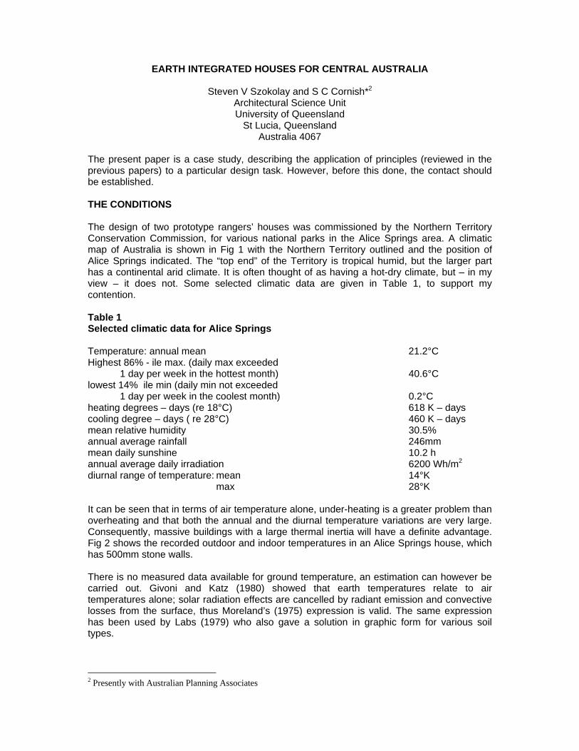
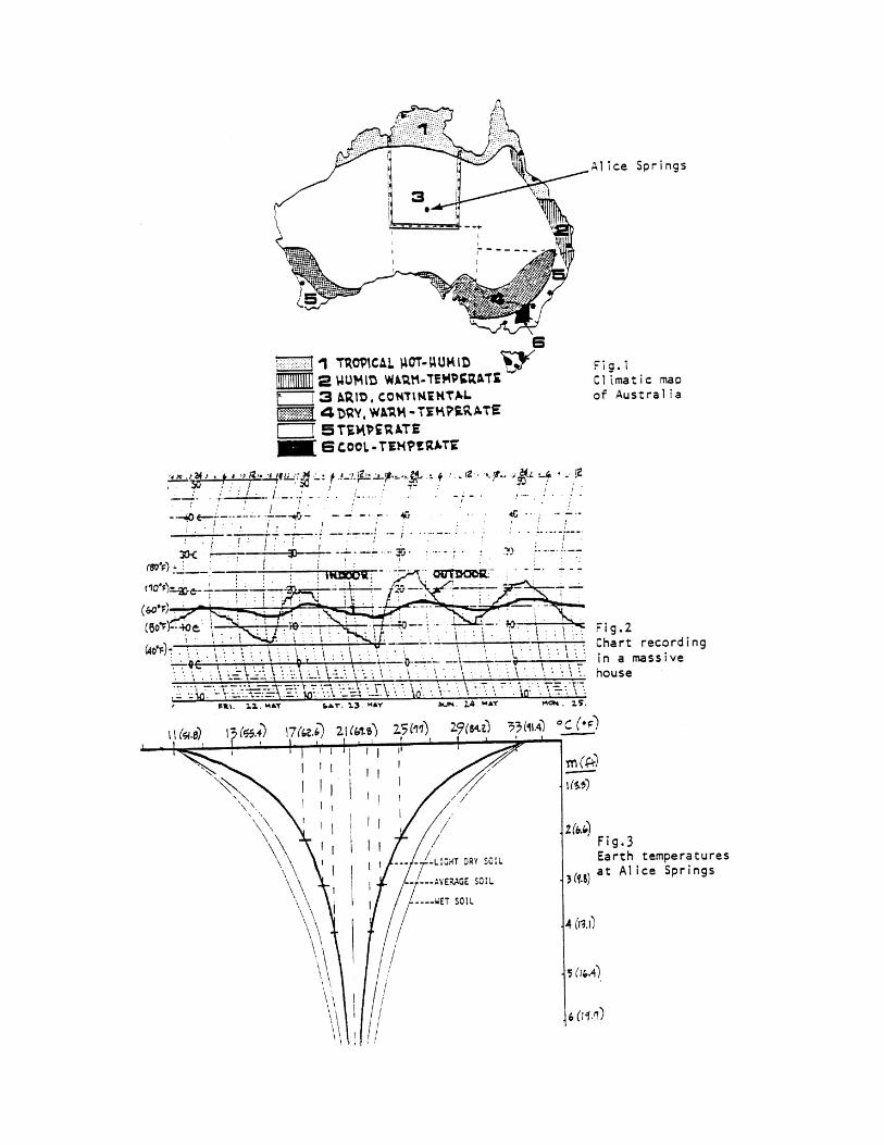
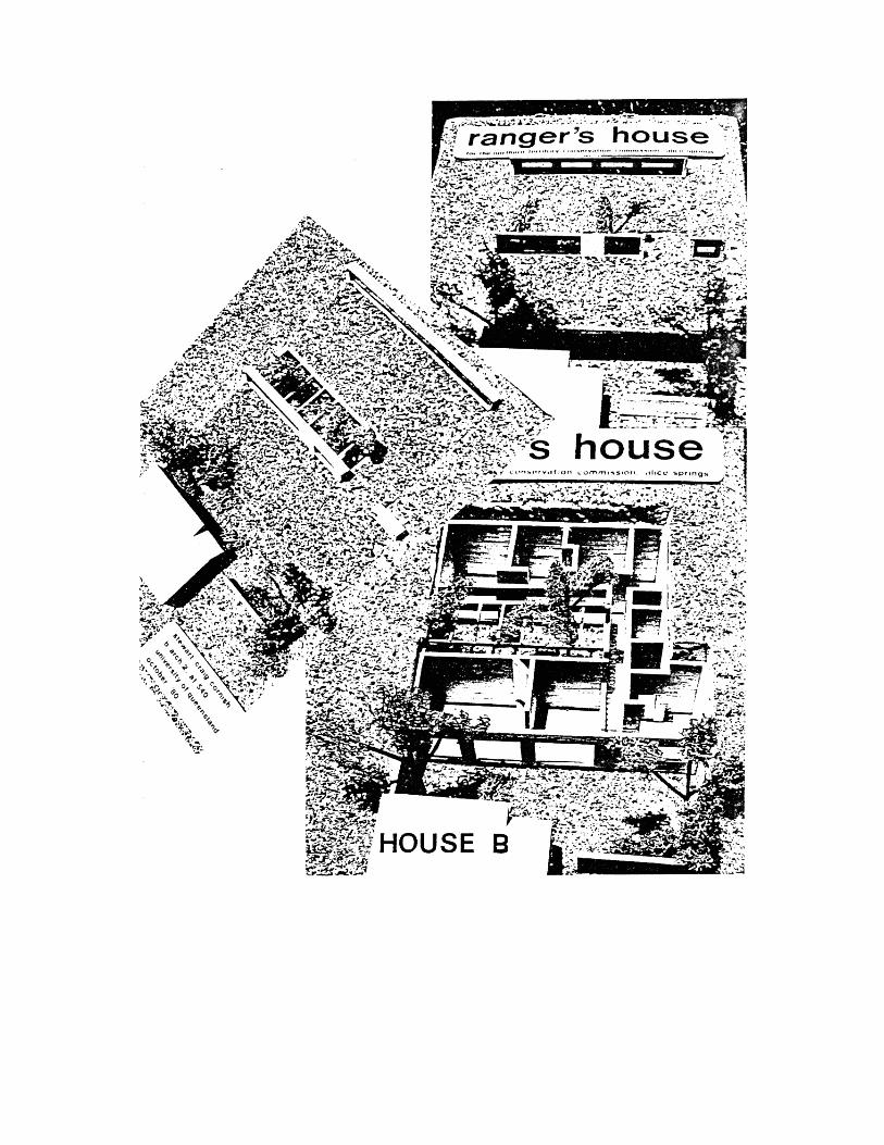
The present paper is a case study, describing the application of principles (reviewed in the previous papers) to a particular design task. However, before this done, the contact should be established. THE CONDITIONS The design of two prototype rangers’ houses was commissioned by the Northern Territory Conservation Commission, for various national parks in the Alice Springs area. A climatic map of Australia is shown in Fig 1 with the Northern Territory outlined and the position of Alice Springs indicated. The “top end” of the Territory is tropical humid, but the larger part has a continental arid climate. It is often thought of as having a hot-dry climate, but – in my view – it does not. Some selected climatic data are given in Table 1, to support my contention. Table 1 Selected climatic data for Alice Springs Temperature: annual mean 21.2°C Highest 86% - ile max. (daily max exceeded 1 day per week in the hottest month) 40.6°C lowest 14% ile min (daily min not exceeded 1 day per week in the coolest month) 0.2°C heating degrees – days (re 18°C) 618 K – days cooling degree – days ( re 28°C) 460 K – days mean relative humidity 30.5% annual average rainfall 246mm mean daily sunshine 10.2 h annual average daily irradiation 6200 Wh/m2 diurnal range of temperature: mean 14°K max 28°K It can be seen that in terms of air temperature alone, under-heating is a greater problem than overheating and that both the annual and the diurnal temperature variations are very large. Consequently, massive buildings with a large thermal inertia will have a definite advantage. Fig 2 shows the recorded outdoor and indoor temperatures in an Alice Springs house, which has 500mm stone walls. There is no measured data available for ground temperature, an estimation can however be carried out. Givoni and Katz (1980) showed that earth temperatures relate to air temperatures alone; solar radiation effects are cancelled by radiant emission and convective losses from the surface, thus Moreland’s (1975) expression is valid. The same expression has been used by Labs (1979) who also gave a solution in graphic form for various soil types.
2 Presently with Australian Planning Associates
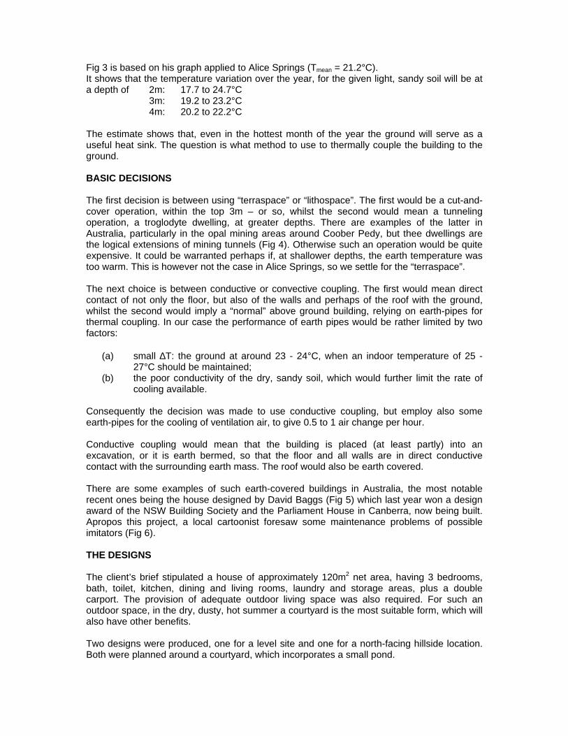
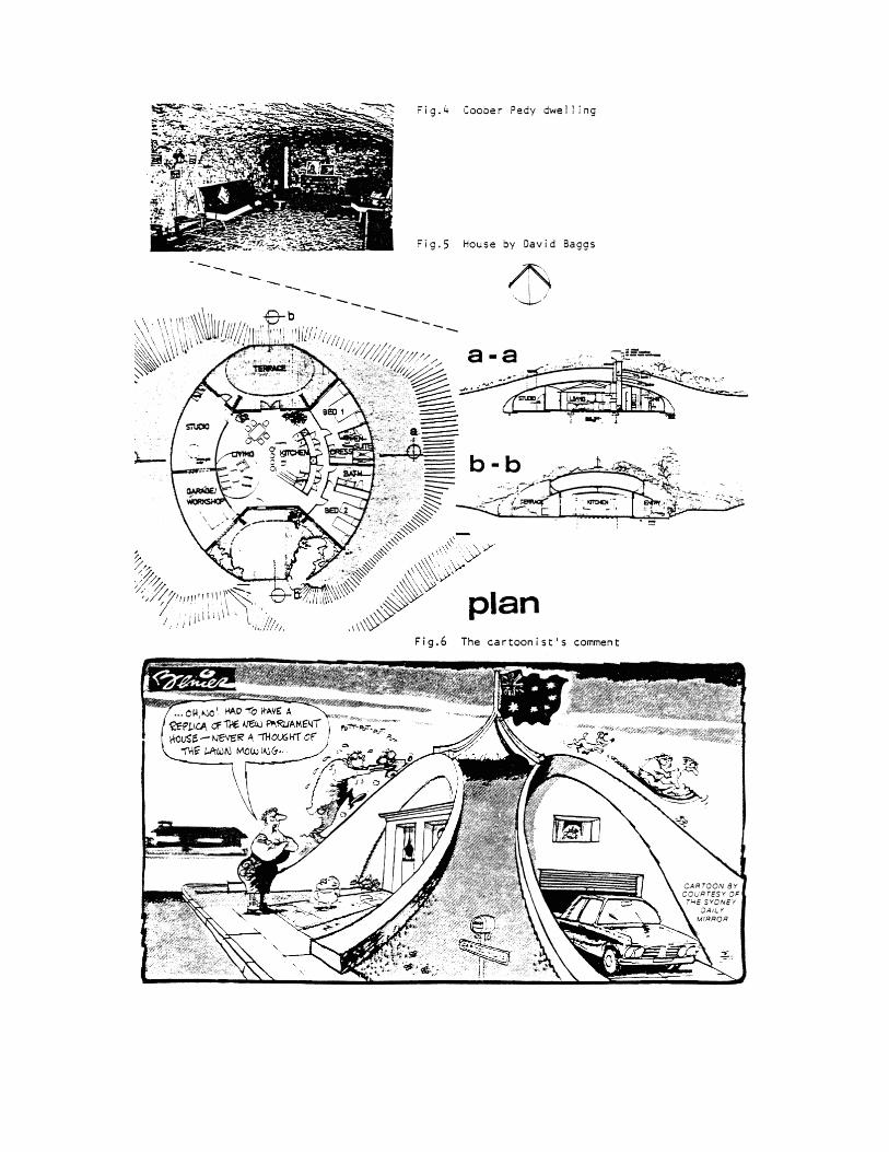
Fig 3 is based on his graph applied to Alice Springs (Tmean = 21.2°C). It shows that the temperature variation over the year, for the given light, sandy soil will be at a depth of 2m: 17.7 to 24.7°C 3m: 19.2 to 23.2°C 4m: 20.2 to 22.2°C The estimate shows that, even in the hottest month of the year the ground will serve as a useful heat sink. The question is what method to use to thermally couple the building to the ground. BASIC DECISIONS The first decision is between using “terraspace” or “lithospace”. The first would be a cut-and-cover operation, within the top 3m – or so, whilst the second would mean a tunneling operation, a troglodyte dwelling, at greater depths. There are examples of the latter in Australia, particularly in the opal mining areas around Coober Pedy, but thee dwellings are the logical extensions of mining tunnels (Fig 4). Otherwise such an operation would be quite expensive. It could be warranted perhaps if, at shallower depths, the earth temperature was too warm. This is however not the case in Alice Springs, so we settle for the “terraspace”. The next choice is between conductive or convective coupling. The first would mean direct contact of not only the floor, but also of the walls and perhaps of the roof with the ground, whilst the second would imply a “normal” above ground building, relying on earth-pipes for thermal coupling. In our case the performance of earth pipes would be rather limited by two factors:
(a) small ∆T: the ground at around 23 - 24°C, when an indoor temperature of 25 - 27°C should be maintained;
(b) the poor conductivity of the dry, sandy soil, which would further limit the rate of cooling available.
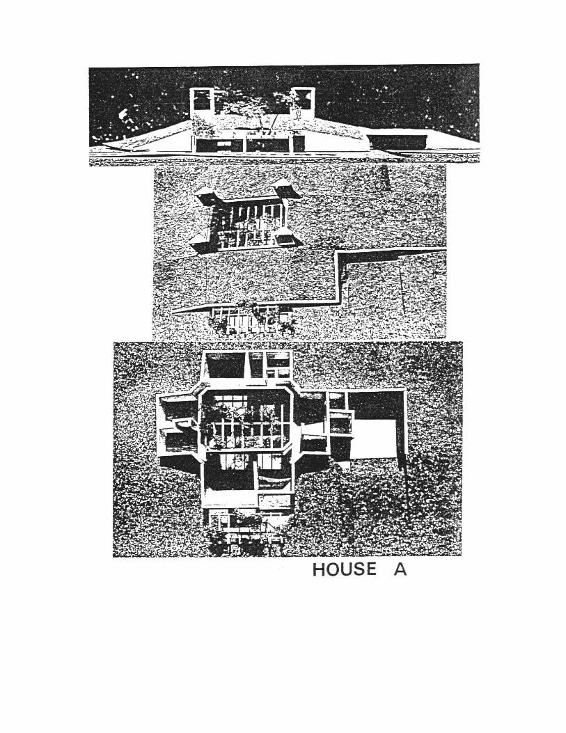
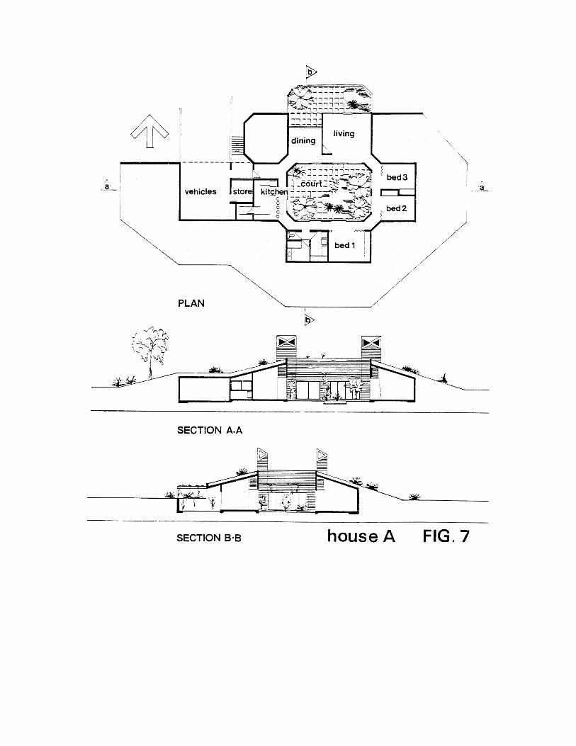
Consequently the decision was made to use conductive coupling, but employ also some earth-pipes for the cooling of ventilation air, to give 0.5 to 1 air change per hour. Conductive coupling would mean that the building is placed (at least partly) into an excavation, or it is earth bermed, so that the floor and all walls are in direct conductive contact with the surrounding earth mass. The roof would also be earth covered. There are some examples of such earth-covered buildings in Australia, the most notable recent ones being the house designed by David Baggs (Fig 5) which last year won a design award of the NSW Building Society and the Parliament House in Canberra, now being built. Apropos this project, a local cartoonist foresaw some maintenance problems of possible imitators (Fig 6). THE DESIGNS The client’s brief stipulated a house of approximately 120m2 net area, having 3 bedrooms, bath, toilet, kitchen, dining and living rooms, laundry and storage areas, plus a double carport. The provision of adequate outdoor living space was also required. For such an outdoor space, in the dry, dusty, hot summer a courtyard is the most suitable form, which will also have other benefits. Two designs were produced, one for a level site and one for a north-facing hillside location. Both were planned around a courtyard, which incorporates a small pond.

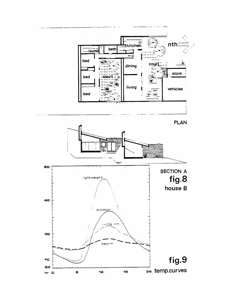
House A (level site) is shown in Fig 7. The site is to be excavated, so that the floor level is 1.2m below natural ground level. The excavated soil is used to berm all external walls and give a roof cover of 500mm depth. This will be covered with turf. With the 150mm r.c. slab supporting it, the roof will give a time-lag of at least 14 hours and an amplitude decrement of less than 0.1. This will reduce the heat flow through the roof to practically nil. The courtyard will be excavated to 600mm below floor level. The pool will be built and the remainder back-filled with 400mm top-soil over a 50mm layer of gravel. At roof level the courtyard will be covered with a “Koolshade’ plastic mesh, partly to reduce the incoming radiation, partly to reduce the convective or wind-caused mixing of the courtyard air with the outside atmosphere, partly to exclude insects. Four solar chimneys are provided at the four corners of the courtyard. When all windows are closed, the solar heat-induced stack effect will draw in air from the courtyard through underground (and under-floor) ducts to the back of each room. The courtyard air temperature is expected to be at least 3°C below that outdoors, as it is evaporatively cooled. Further cooling would be provided by the ducts acting as ‘earth pipes’. A second, sunken and semi-enclosed court is located on the north side of the living/dining rooms. This would allow winter sun-penetration into the two rooms and provide an outdoor living space for cool winter days. House B (hillside) is shown in Fig 8. Similar in concept to the above but utilising the advantages of the hillside location two ways:
(a) the excavation is deeper so that the rear part (bedrooms) is completely underground, natural shade is restored with the roof backfill. The outer edge of the front court will reach natural grade;
(b) having a split-level plan, so that the bedroom wing is at a level 1.5m above the living zone.
The major difference is in the design of the solar chimneys. Here they take the form of al elongated narrow panel as a continuation upwards of the rear wall of both the bedrooms and the kitchen-living-dining rooms. For both houses the main construction material is hollow concrete blocks. Walls of the solar chimneys are also made of concrete blocks, the inside painted black and the front (facing north) being glazed, with air outlets located near the top. PERFORMANCE PREDICTION Using the computer program HAMON, developed by P Ritson at the Architectural Science Unit, a series of thermal response simulations were carried out. Fig 9 shows just one example: the expected indoor “environmental temperatures” in house B (Te = 1/3 DBT + 2.3 MRT) on a typical January (summer) day in comparison with similar temperatures in a recently built lightweight house in the same location and with the outdoor DBT profile. In this simulation, ventilation rates were taken as 3 air changes per hour from 19.00 to 8.00 h, whilst only 0.5 air change per hour during the daytime. The bedrooms, with their closer earth-coupling show an almost steady temperature, a diurnal swing less than 3°K. The living room, which is more exposed, shows a swing of about 7°K, but even here, the maximum is only 32°C when the outdoor temperature reaches 36.5°C.

EPILOGUE The designs submitted to the client, the Northern Territory Conservation Commission, were very well received. Both professional and management staff were pleased, and several persons remarked: “I wouldn’t mind living in one of these”. However, when the design drawings and models where shown to the future occupants (park rangers), their reaction was completely negative: “What? You want to put us underground? No way! We want proper houses!” As a result, the houses are unlikely to be built. REFERENCES Givoni, B and Katz, L. (1980): Earth temperatures and underground buildings. (Unpublished paper – private communication). Labs, K. (1979): Underground building climate. Solar Age Oct pp 44-50. Moreland, F L. (1975): An alternative so suburbia. Alternatives in Energy conf Ft Worth, Texas. July. US Government Printing Office, pp 203-204.
VEGETATION EFFECTS ON EARTH COOLING POTENTIAL
Sydney A. Baggs School of Landscape Architecture
The University of New South Wales P O Box 1, Kensington NSW
Sydney, Australia 2033
ABSTRACT Ground temperature data from various sites throughout five States of Australia at depths to 200 cm (6.6 feet) in locations exposed to continuous direct sun, and within adjacent vegetation shade, are applied to a simple ground temperature equation modified for Australian conditions. The equation is then used to extrapolate tautochrone ground temperature data for a specific depth on an annual basis and for depths relevant to the design of earth-covered buildings. As vegetation appears to function as an intervening medium between the periodic temperature change of ambient air (that functions as a driving mechanism) and the soil beneath, it becomes possible to damp the amplitude of the ground temperature wave by the use of landscape planting and thus manipulate soil climate temperature and comfort conditions within an underground building. INTRODUCTION In order to combine both energy and environmental conservation principles, it is necessary to know about the effects of vegetative cover upon soil temperature, and the possibilities of modifying the latter by the careful selection of appropriate vegetation for roof landscaping and surrounds. In the literature. it has been shown that vegetation shade (and associated root zones) modified soil climate temperature (1, 2). However, this effect has not been quantified on an annual basis, or in terms of various Australian vegetation growth forms and floristic types. GROUND TEMPERATURE EQUATION FOR AUSTRALIAN CONDITIONS Once an equation was established that would satisfactorily predict ground temperatures at sites remote from the assessor, it would be possible for the validated equation to be applied to other sites throughout the continent, facilitating the graphical illustration of ground temperature cycles within the upper zone of the ground (q. v.), for soils exposed to full sun and in specific proportions of vegetation shade. Data derived therefrom would then be used to develop preliminary ground temperature isothermal contour maps. Predicted ground temperatures would be considered acceptable for use in feasibility studies on underground housing if they were within a range of approximately ± 2C° when compared with on-site survey ground temperature readings for depths of 200 cm or more.
From the literature (3) a well-established mathematical equation relating ground temperatures to easily-accessed meteorological data for any site that had been used for northern hemisphere research, was adopted as a means of predicting periodic ground temperature change within an acceptable range. The principal above-ground factors that are determinants of ground temperature in the upper and transition zones are: incident and reflected solar radiation, together with the site-specific variables of weather, topoclimate, and microclimate (4) and vegetation / evapotranspiration (5). However ,"all these influencing quantities are themselves influenced in some manner by the air temperature," and adoption of a model that uses air temperature as a driving mechanism to effect ground temperature change appeared to be a reasonable approach. If a
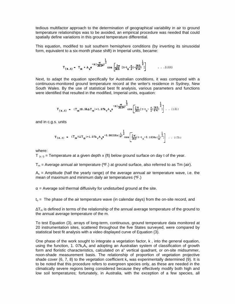
tedious multifactor approach to the determination of geographical variability in air to ground temperature relationships was to be avoided, an empirical procedure was needed that could spatially define variations in this ground temperature differential. This equation, modified to suit southern hemisphere conditions (by inverting its sinusoidal form, equivalent to a six-month phase shift) in Imperial units, became:
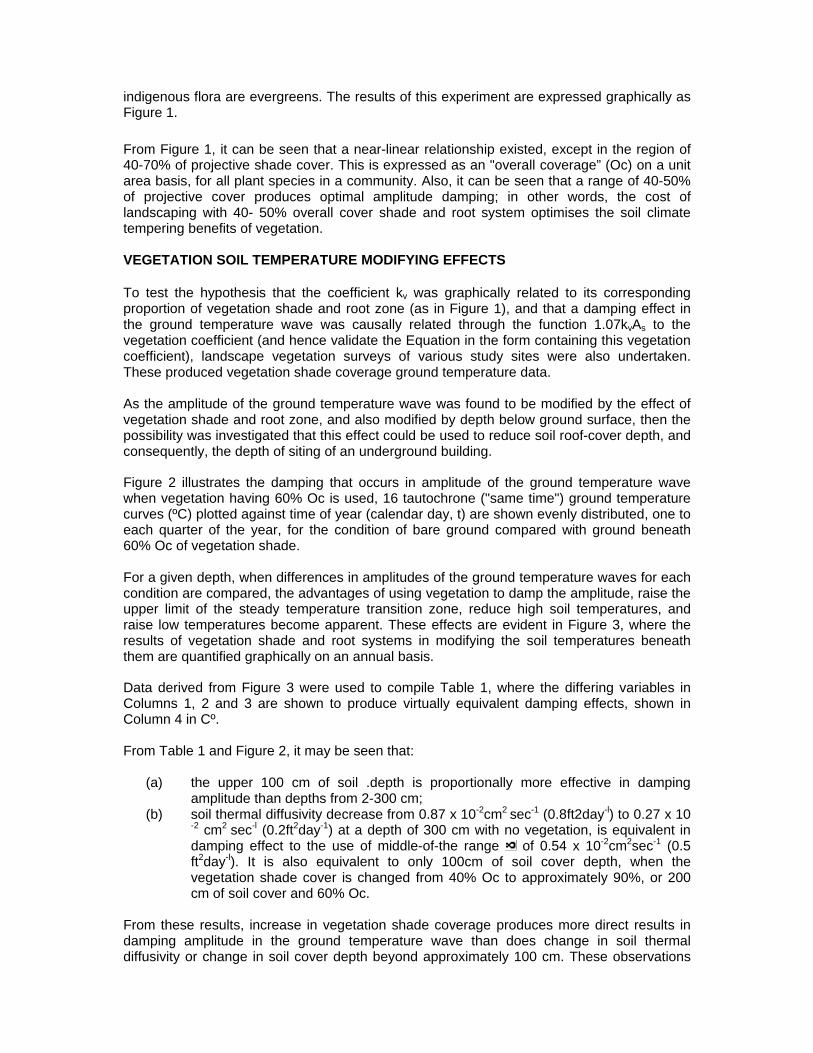
Next, to adapt the equation specifically for Australian conditions, it was compared with a continuous-monitored ground temperature record at the writer's residence in Sydney, New South Wales. By the use of statistical best fit analysis, various parameters and functions were identified that resulted in the modified, Imperial units, equation:
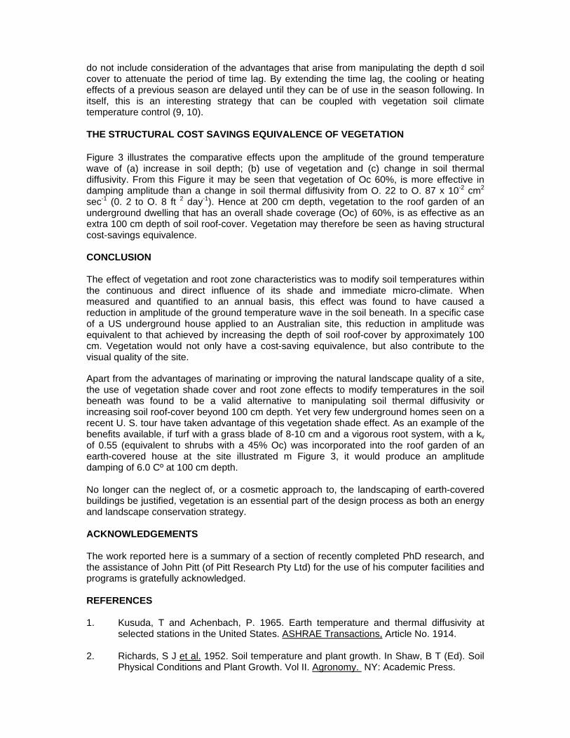
and in c.g.s. units
where: T (x. t) = Temperature at a given depth x (ft) below ground surface on day t of the year. Tm = Average annual air temperature (ºF.) at ground surface, also referred to as Tm (air).
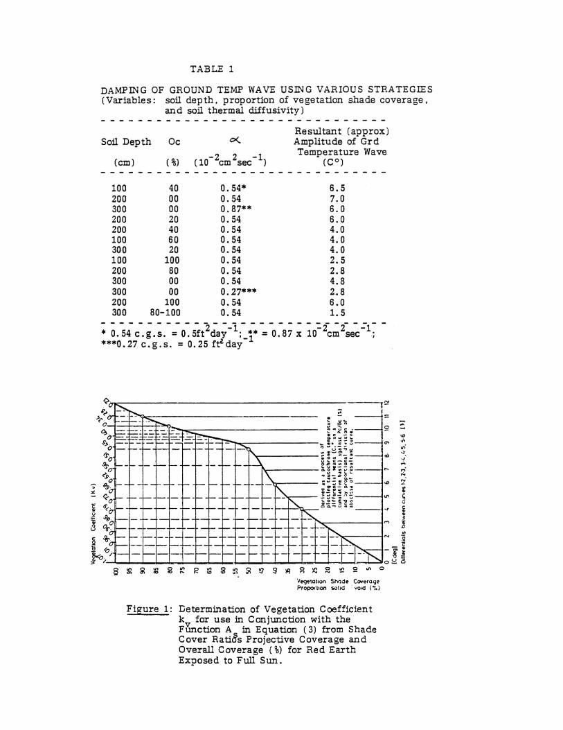
As = Amplitude (half the yearly range) of the average annual air temperature wave, i.e. the mean of maximum and minimum daily air temperatures (ºF.) α = Average soil thermal diffusivity for undisturbed ground at the site. to = The phase of the air temperature wave (in calendar days) from the on-site record, and ∆Tm is defined in terms of the relationship of the annual average temperature of the ground to the annual average temperature of the m. To test Equation (3), arrays of long-term, continuous, ground temperature data monitored at 20 instrumentation sites, scattered throughout the five States surveyed, were compared by statistical best fit analysis with a video displayed curve of Equation (3). One phase of the work sought to integrate a vegetation factor, k , into the general equation, using the function, 1. 07kvAs and adopting an Australian system of classification of growth form and floristic characteristics, calculated on a" vertical quadrant, or on-site midsummer, noon-shade measurement basis. The relationship of proportion of vegetation projective shade cover (6, 7, 8) to the vegetation coefficient kv was experimentally determined (9). It is to be noted that this procedure refers to evergreen species only, as these are needed in the climatically severe regions being considered because they effectively modify both high and low soil temperatures; fortunately, in Australia, with the exception of a few species, all
indigenous flora are evergreens. The results of this experiment are expressed graphically as Figure 1. From Figure 1, it can be seen that a near-linear relationship existed, except in the region of 40-70% of projective shade cover. This is expressed as an "overall coverage” (Oc) on a unit area basis, for all plant species in a community. Also, it can be seen that a range of 40-50% of projective cover produces optimal amplitude damping; in other words, the cost of landscaping with 40- 50% overall cover shade and root system optimises the soil climate tempering benefits of vegetation. VEGETATION SOIL TEMPERATURE MODIFYING EFFECTS To test the hypothesis that the coefficient kv was graphically related to its corresponding proportion of vegetation shade and root zone (as in Figure 1), and that a damping effect in the ground temperature wave was causally related through the function 1.07kvAs to the vegetation coefficient (and hence validate the Equation in the form containing this vegetation coefficient), landscape vegetation surveys of various study sites were also undertaken. These produced vegetation shade coverage ground temperature data. As the amplitude of the ground temperature wave was found to be modified by the effect of vegetation shade and root zone, and also modified by depth below ground surface, then the possibility was investigated that this effect could be used to reduce soil roof-cover depth, and consequently, the depth of siting of an underground building.
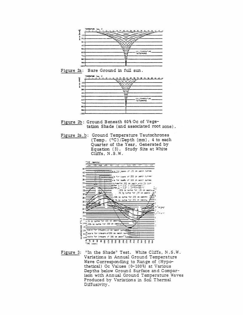
Figure 2 illustrates the damping that occurs in amplitude of the ground temperature wave when vegetation having 60% Oc is used, 16 tautochrone ("same time") ground temperature curves (ºC) plotted against time of year (calendar day, t) are shown evenly distributed, one to each quarter of the year, for the condition of bare ground compared with ground beneath 60% Oc of vegetation shade. For a given depth, when differences in amplitudes of the ground temperature waves for each condition are compared, the advantages of using vegetation to damp the amplitude, raise the upper limit of the steady temperature transition zone, reduce high soil temperatures, and raise low temperatures become apparent. These effects are evident in Figure 3, where the results of vegetation shade and root systems in modifying the soil temperatures beneath them are quantified graphically on an annual basis.
Data derived from Figure 3 were used to compile Table 1, where the differing variables in Columns 1, 2 and 3 are shown to produce virtually equivalent damping effects, shown in Column 4 in Cº. From Table 1 and Figure 2, it may be seen that:
(a) the upper 100 cm of soil .depth is proportionally more effective in damping amplitude than depths from 2-300 cm;
(b) soil thermal diffusivity decrease from 0.87 x 10⁻²cm2 sec-1 (0.8ft2day-l) to 0.27 x 10 -2 cm2 sec-l (0.2ft2day-1) at a depth of 300 cm with no vegetation, is equivalent in damping effect to the use of middle-of-the range of 0.54 x 10⁻²cm2sec-1 (0.5 ft2day-l). It is also equivalent to only 100cm of soil cover depth, when the vegetation shade cover is changed from 40% Oc to approximately 90%, or 200 cm of soil cover and 60% Oc.
From these results, increase in vegetation shade coverage produces more direct results in damping amplitude in the ground temperature wave than does change in soil thermal diffusivity or change in soil cover depth beyond approximately 100 cm. These observations
do not include consideration of the advantages that arise from manipulating the depth d soil cover to attenuate the period of time lag. By extending the time lag, the cooling or heating effects of a previous season are delayed until they can be of use in the season following. In itself, this is an interesting strategy that can be coupled with vegetation soil climate temperature control (9, 10). THE STRUCTURAL COST SAVINGS EQUIVALENCE OF VEGETATION Figure 3 illustrates the comparative effects upon the amplitude of the ground temperature wave of (a) increase in soil depth; (b) use of vegetation and (c) change in soil thermal diffusivity. From this Figure it may be seen that vegetation of Oc 60%, is more effective in damping amplitude than a change in soil thermal diffusivity from O. 22 to O. 87 x 10-2 cm2
sec-1 (0. 2 to O. 8 ft 2 day-1). Hence at 200 cm depth, vegetation to the roof garden of an underground dwelling that has an overall shade coverage (Oc) of 60%, is as effective as an extra 100 cm depth of soil roof-cover. Vegetation may therefore be seen as having structural cost-savings equivalence. CONCLUSION The effect of vegetation and root zone characteristics was to modify soil temperatures within the continuous and direct influence of its shade and immediate micro-climate. When measured and quantified to an annual basis, this effect was found to have caused a reduction in amplitude of the ground temperature wave in the soil beneath. In a specific case of a US underground house applied to an Australian site, this reduction in amplitude was equivalent to that achieved by increasing the depth of soil roof-cover by approximately 100 cm. Vegetation would not only have a cost-saving equivalence, but also contribute to the visual quality of the site.
Apart from the advantages of marinating or improving the natural landscape quality of a site, the use of vegetation shade cover and root zone effects to modify temperatures in the soil beneath was found to be a valid alternative to manipulating soil thermal diffusivity or increasing soil roof-cover beyond 100 cm depth. Yet very few underground homes seen on a recent U. S. tour have taken advantage of this vegetation shade effect. As an example of the benefits available, if turf with a grass blade of 8-10 cm and a vigorous root system, with a kv of 0.55 (equivalent to shrubs with a 45% Oc) was incorporated into the roof garden of an earth-covered house at the site illustrated m Figure 3, it would produce an amplitude damping of 6.0 Cº at 100 cm depth. No longer can the neglect of, or a cosmetic approach to, the landscaping of earth-covered buildings be justified, vegetation is an essential part of the design process as both an energy and landscape conservation strategy. ACKNOWLEDGEMENTS The work reported here is a summary of a section of recently completed PhD research, and the assistance of John Pitt (of Pitt Research Pty Ltd) for the use of his computer facilities and programs is gratefully acknowledged. REFERENCES 1. Kusuda, T and Achenbach, P. 1965. Earth temperature and thermal diffusivity at
selected stations in the United States. ASHRAE Transactions, Article No. 1914. 2. Richards, S J et al. 1952. Soil temperature and plant growth. In Shaw, B T (Ed). Soil
Physical Conditions and Plant Growth. Vol II. Agronomy. NY: Academic Press.
3. Labs, K. 1978. Underground building climate, Solar Age, Vol 4 No. 10. 4. Kuiper, L, 1976. A thermal model for the surface temperature of materials on the
earth’s surface. Tech Inf. No. 1. Iowa: Geol. Survey. July. 5. Hasfurther, V and Burman, R. 1974. Soil temperature modeling using air temperature
as a driving mechanism. Transactions of the ASAE. 6. Atlas of Australian Resources. 1976. Natural Vegetation. 2nd series, Geog. Sect. Div.
Nat. Mapping, Dept of Nat. Res. Canberra: J A Carnahan. Canberra: ANU. 7. Carnahan, J A. 1977. Vegetation. In Jeans, D. (Ed). Australia, A Geography Sydney:
Sydney UP. 8. Specht, R. 1970. Vegetation. In Leeper, G W (Ed). The Australian Environment. (4th
ed). Melbourne C.S.I.R.O. Melb UP. 9. Baggs, S. 1981. Underground housing for the Australian arid region: prediction of
periodic ground temperature change, effects of certain landscape factors upon ground temperature, and socio-psychological factors in user-acceptance. PhD pending. The University of NSW.
10. Kusuda, T and Peavy, B. 1975. The effect of ground cover on earth temperature. In
Moreland, F. (Ed). Alternatives in Energy Conservation: The Use of Earth Covered Buildings, conf. Proc. 9 – 12 July, Texas.
BUILDING DESIGN FOR EARTH COOLING
Walter T Grondzik School of Architecture, Division of Engineering
Oklahoma State University Stillwater. Oklahoma 74078 USA
INTRODUCTION Earth sheltered structures possess several inherent features, such as long term thermal stability, reduced heat gain and access to the heat sink capability of surrounding soil, which make them ready vehicles for the application of earth coupled cooling techniques (1, 2). Such cooling may be accomplished via passive direct heat transfer methods or via the use of equipment-assisted remote heat transfer using cool tubes or heat pumps. Space cooling via the passive direct contact mode is the focus of this paper.
Background
The summer coolness often experienced in buried structures as diverse as food cellars, storm shelters and conventional basements bears testimony to the benefits of earth contact cooling. Unfortunately, the negative connotations normally associated with these types of unoccupied spaces are often projected to occupied earth shelters as well. Experience indicates that proper selection of waterproofing and air circulation systems can eliminate the dank, musty conditions encountered in poorly designed underground spaces (3, 4). Comfort and Cooling Comfort cooling is a complex process, involving control of air movement and humidity, as well as air temperature. In addition, mean radiant temperature (MRT) benefits must be considered in direct loss (earth contact) cooling applications.
MRT is an area and distance-weighted average of the surface temperatures encountered in a space (5). Although authorities differ on the exact value of an MR T-air temperature tradeoff, it is generally accepted that a one degree drop in MRT can compensate for a one-degree rise in air temperature. For example, comfort equivalent to that experienced at 78°F (25.6°C) can be obtained in a space with an 80°F (26.7°C) air temperature but a 76°F (24.4°C) MRT. An understanding of these interrelated variables is critical to the successful utilization of earth contact cooling.
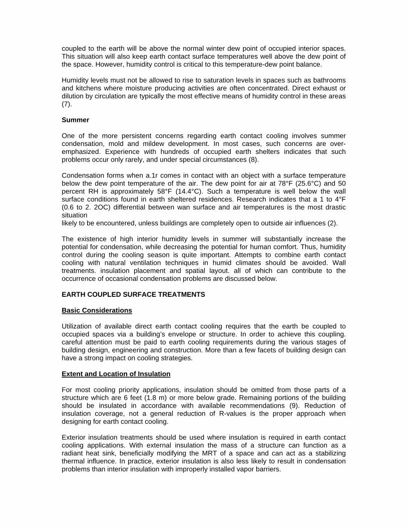
EARTH COOLING POTENTIAL Regional Characteristics
The need for, and the availability of, earth coupled cooling benefits are regional in nature. In general, there is an inverse relationship between climatologically induced cooling loads and climatically produced cooling potential. Those regions with the greatest needs tend to have the warmest soils. Figure 1 provides a graphic analysis of this situation. Because of this combination of increased need and reduced availability, the design techniques discussed below are of great importance. In all regions of the country, earth coupled cooling must be considered in context with other possible cooling strategies such as natural ventilation, thermal mass or conventional air conditioning (6).
Building Scale
The size, scale and configuration of a building will greatly influence the magnitude of those impacts which might be expected from earth contact cooling designs. A residential scale structure, which is primarily envelope load dominated, also has a reasonably good ratio of heat sink area to floor area. A conventional internal-load dominated building, such as a large office, will normally show a low sink-to-floor-area ratio. In addition, the nature and source of loads in a commercial scale structure differ from those encountered in a residence. Latent (moisture based) loads are typically more critical with respect to acceptable design levels in commercial structures. Such loads are not amenable to mitigation via direct earth contact cooling.
The heat gain reduction impacts of earth sheltering are proportionally greater in envelope-dominated buildings than in internal-load dominated buildings. As a result of these factors, earth contact cooling will be most effective in smaller structures, especially residences. SEASONAL DESIGN CONSIDERATIONS Summer Design Approach
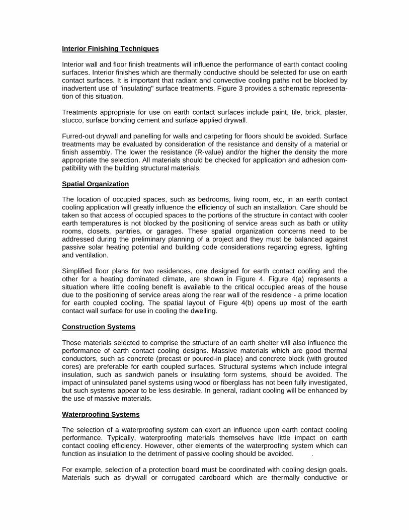
The essence of designing for earth contact cooling is reflected in Figure 2. Those portions of a building in contact with cooler summer soil temperatures are not insulated, permitting heat flow from the warm building to the cool soil. Those portions of a building in contact with soil temperatures which are continuously above design summer comfort conditions are insulated, to an extent dictated by economics, to reduce heat gain to the occupied space. Those parts of a building structure which can provide benefits from summer soil contact are coupled to the earth's heat sink. Typically this involves the building floor and the lower portions of the earth-backed walls. Those parts of the building where no benefit will accrue from soil contact, normally the roof and upper wall sections, are decoupled from the earth by insulation treatments. The use of substantial amounts of earth cover, or deliberate soil temperature modification techniques such as evaporative cooling or solar shading, can enhance the potential of the roof and upper walls as possible sources of passive cooling. Winter Design Tradeoffs
In many cases, earth cooling requirements may conflict with winter heating design dictates. Omission of selected insulation may increase a building's design heat loss. In fact, a balance must be struck between winter and summer design requirements. This is particularly true in the temperate regions of the United States which experience both hot summers and cold winters. In these situations a design decision must be made as to the relative value of increased winter load versus decreased summer load. In most temperate or hot regions of the United States both utility rate and thermal comfort considerations will favor the cooling design requirements. In addition, several alternative source heating options such as solar energy or wood are readily adaptable to earth sheltered residences to offset winter losses. Alternative source cooling options, on the other hand, are often quite limited or non-existent. Prevention of Condensation Winter Winter soil temperatures adjacent to the floor and lower walls of an earth shelter directly
coupled to the earth will be above the normal winter dew point of occupied interior spaces. This situation will also keep earth contact surface temperatures well above the dew point of the space. However, humidity control is critical to this temperature-dew point balance. Humidity levels must not be allowed to rise to saturation levels in spaces such as bathrooms and kitchens where moisture producing activities are often concentrated. Direct exhaust or dilution by circulation are typically the most effective means of humidity control in these areas (7). Summer One of the more persistent concerns regarding earth contact cooling involves summer condensation, mold and mildew development. In most cases, such concerns are over-emphasized. Experience with hundreds of occupied earth shelters indicates that such problems occur only rarely, and under special circumstances (8). Condensation forms when a.1r comes in contact with an object with a surface temperature below the dew point temperature of the air. The dew point for air at 78°F (25.6°C) and 50 percent RH is approximately 58°F (14.4°C). Such a temperature is well below the wall surface conditions found in earth sheltered residences. Research indicates that a 1 to 4°F (0.6 to 2. 2OC) differential between wan surface and air temperatures is the most drastic situation likely to be encountered, unless buildings are completely open to outside air influences (2). The existence of high interior humidity levels in summer will substantially increase the potential for condensation, while decreasing the potential for human comfort. Thus, humidity control during the cooling season is quite important. Attempts to combine earth contact cooling with natural ventilation techniques in humid climates should be avoided. Wall treatments. insulation placement and spatial layout. all of which can contribute to the occurrence of occasional condensation problems are discussed below. EARTH COUPLED SURFACE TREATMENTS Basic Considerations Utilization of available direct earth contact cooling requires that the earth be coupled to occupied spaces via a building’s envelope or structure. In order to achieve this coupling. careful attention must be paid to earth cooling requirements during the various stages of building design, engineering and construction. More than a few facets of building design can have a strong impact on cooling strategies. Extent and Location of Insulation For most cooling priority applications, insulation should be omitted from those parts of a structure which are 6 feet (1.8 m) or more below grade. Remaining portions of the building should be insulated in accordance with available recommendations (9). Reduction of insulation coverage, not a general reduction of R-values is the proper approach when designing for earth contact cooling. Exterior insulation treatments should be used where insulation is required in earth contact cooling applications. With external insulation the mass of a structure can function as a radiant heat sink, beneficially modifying the MRT of a space and can act as a stabilizing thermal influence. In practice, exterior insulation is also less likely to result in condensation problems than interior insulation with improperly installed vapor barriers.
Interior Finishing Techniques
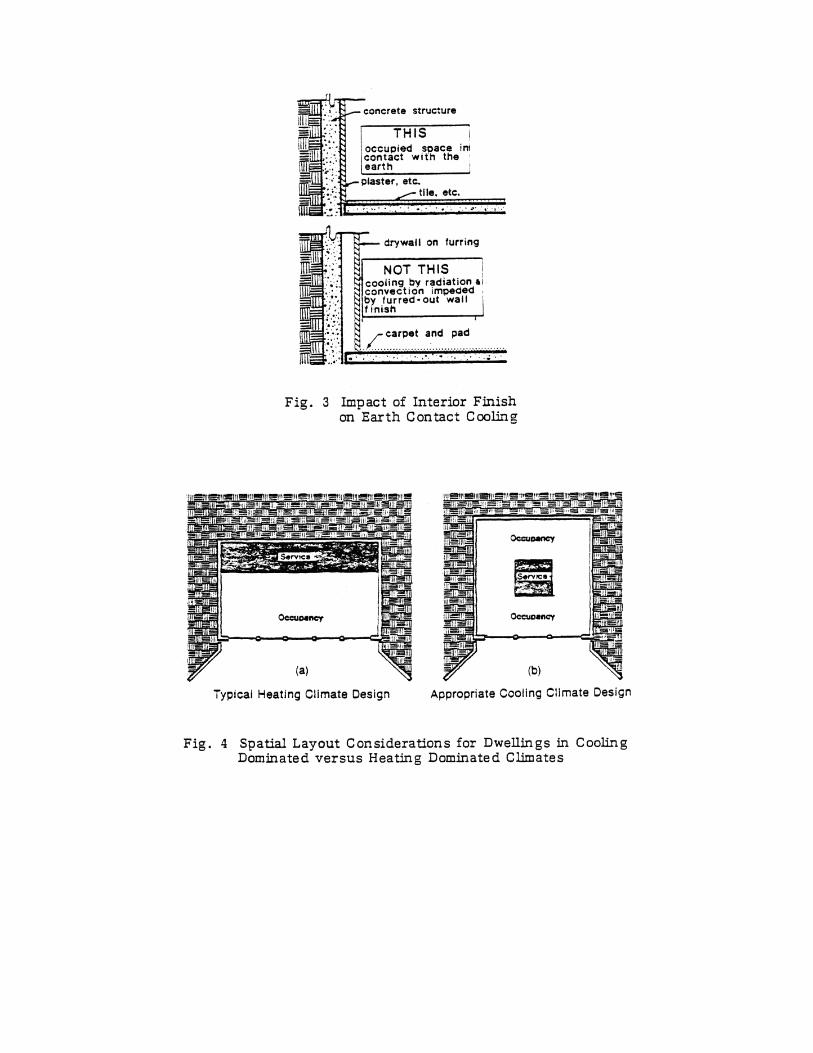
Interior wall and floor finish treatments will influence the performance of earth contact cooling surfaces. Interior finishes which are thermally conductive should be selected for use on earth contact surfaces. It is important that radiant and convective cooling paths not be blocked by inadvertent use of "insulating" surface treatments. Figure 3 provides a schematic representa-tion of this situation. Treatments appropriate for use on earth contact surfaces include paint, tile, brick, plaster, stucco, surface bonding cement and surface applied drywall. Furred-out drywall and panelling for walls and carpeting for floors should be avoided. Surface treatments may be evaluated by consideration of the resistance and density of a material or finish assembly. The lower the resistance (R-value) and/or the higher the density the more appropriate the selection. All materials should be checked for application and adhesion com-patibility with the building structural materials. Spatial Organization
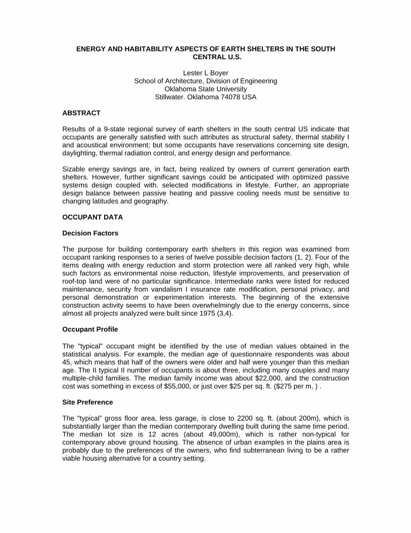
The location of occupied spaces, such as bedrooms, living room, etc, in an earth contact cooling application will greatly influence the efficiency of such an installation. Care should be taken so that access of occupied spaces to the portions of the structure in contact with cooler earth temperatures is not blocked by the positioning of service areas such as bath or utility rooms, closets, pantries, or garages. These spatial organization concerns need to be addressed during the preliminary planning of a project and they must be balanced against passive solar heating potential and building code considerations regarding egress, lighting and ventilation. Simplified floor plans for two residences, one designed for earth contact cooling and the other for a heating dominated climate, are shown in Figure 4. Figure 4(a) represents a situation where little cooling benefit is available to the critical occupied areas of the house due to the positioning of service areas along the rear wall of the residence - a prime location for earth coupled cooling. The spatial layout of Figure 4(b) opens up most of the earth contact wall surface for use in cooling the dwelling. Construction Systems Those materials selected to comprise the structure of an earth shelter will also influence the performance of earth contact cooling designs. Massive materials which are good thermal conductors, such as concrete (precast or poured-in place) and concrete block (with grouted cores) are preferable for earth coupled surfaces. Structural systems which include integral insulation, such as sandwich panels or insulating form systems, should be avoided. The impact of uninsulated panel systems using wood or fiberglass has not been fully investigated, but such systems appear to be less desirable. In general, radiant cooling will be enhanced by the use of massive materials. Waterproofing Systems
The selection of a waterproofing system can exert an influence upon earth contact cooling performance. Typically, waterproofing materials themselves have little impact on earth contact cooling efficiency. However, other elements of the waterproofing system which can function as insulation to the detriment of passive cooling should be avoided. . For example, selection of a protection board must be coordinated with cooling design goals. Materials such as drywall or corrugated cardboard which are thermally conductive or
biodegradable should be used where required to provide protection for waterproofing membranes. The use of insulation or insulating sheathing boards on earth contact surfaces should be avoided. Materials used for backfill must be evaluated from a thermal perspective as well. Backfill materials which involve large air voids can establish an exterior dead air space around a building. Porous, well draining fill such as an earth/sand mixture should be used in lieu of large-void gravel or commercially available drainage bed spacers. Earth Covered Roofs The cooling benefits associated with earth covered roofs are of a lower magnitude than the benefits associated with earth contact wall and floor surfaces. In fact, most typical earth covered roof installations probably provide no season-long cooling per se. However, the heat gain reduction capability of earth covered roofs can be quite substantial (2). A number of factors influence the performance of such roofs (10, 11). Selection of an earth cover depth can have a dramatic impact on building cost as well as performance. For cooling purposes, a roof cover depth of roughly 2 to 4 feet (0.6 to 1.2 m) appears reasonable. Shallow depths of earth cover incur the same waterproofing and structural liabilities as more substantial covers without providing similar benefits. In addition, maintenance of a viable ground cover over shallow earth fills can be quite difficult in many parts of the world. On the other hand, an earth cover depth in excess of 6 feet (1.8 m) can totally alter the structural economics of a residential scale building, while still not providing substantial comfort cooling input. REFERENCES 1. Grondzik, WT, L L Boyer and T L Johnston: “Earth Coupled Cooling Techniques”,
Proc. 6th National Passive Solar Conf., Portland, AS/ISES, 1981. 2. US Dept of Energy: Earth Sheltered Structures Fact Sheets, prepared by Centre for
Natural Energy Design, School of Architecture, Oklahoma State University, August 1981 – No. 09. Earth Coupled Cooling Techniques ORNL/SUB-69741V-03.
3. Boyer, L L, W T, Grondzik and M J Weber: “Passive Energy Design and Habitability
Aspects of Earth Sheltered Housing in Oklahoma”, Underground Space, 4(6): 333, 1980.
4. Boyer, L L and W T Grondzik: “Habitability and Energy Performance of Earth
Sheltered Dwellings”, Proc. Of 3rd International Conf. On Alternative Energy Sources, T N Veziroglu (Ed), Miami Beach, 1980.
5. Olgyay, V: Design with Climate, Princeton University Press, Princeton, 1963. 6. Labs, K and D Watson: “Regional Suitability of Earth Tempering”, Proc of Earth
Shelter Performance and Evaluation Conf., L L Boyer (Ed), Oklahoma State University, Stillwater, 1981.
7. US Dept of Energy: Earth Sheltered Structures Fact Sheets, Prepared by Centre for
Natural Energy Design, School of Architecture, Oklahoma State University, August 1981 No. 08 Indoor Air Quality ORNL/SUB-69741V-02.
8. Weber, M J, L L Boyer and W T Grondzik: “Implications for Habitability Design and
Energy Savings in Earth Sheltered Housing”, Proc of Earth Shelter Design

Innovations Conf., L L Boyer (Ed), Oklahoma State University, Stillwater, 1980. 9. US Dept of Energy: Earth Sheltered Structures Fact Sheets, Prepared by
Underground Space Centre, University of Minnesota, May 1981 – No. 05 Insulation Principles ORNL/SUB-7849/05.
10. Baggs, S A: “Effects of Vegetation on Earth Cooling Potential”, Proc of Earth Shelter
Performance and Evaluation Conf., L L Boyer (Ed)., Oklahoma State University, Stillwater, 1981.
11. Grondzik, W T, L L Boyer and T L Johnson: “Variations in Earth Covered Roof
Temperature Profiles”, Proc. International Passive and Hybrid Cooling Conf., Miami Beach, AS/ISES, 1981.
ENERGY AND HABITABILITY ASPECTS OF EARTH SHELTERS IN THE SOUTH CENTRAL U.S.
Lester L Boyer
School of Architecture, Division of Engineering Oklahoma State University
Stillwater. Oklahoma 74078 USA
ABSTRACT Results of a 9-state regional survey of earth shelters in the south central US indicate that occupants are generally satisfied with such attributes as structural safety, thermal stability I and acoustical environment; but some occupants have reservations concerning site design, daylighting, thermal radiation control, and energy design and performance. Sizable energy savings are, in fact, being realized by owners of current generation earth shelters. However, further significant savings could be anticipated with optimized passive systems design coupled with. selected modifications in lifestyle. Further, an appropriate design balance between passive heating and passive cooling needs must be sensitive to changing latitudes and geography. OCCUPANT DATA Decision Factors The purpose for building contemporary earth shelters in this region was examined from occupant ranking responses to a series of twelve possible decision factors (1, 2). Four of the items dealing with energy reduction and storm protection were all ranked very high, while such factors as environmental noise reduction, lifestyle improvements, and preservation of roof-top land were of no particular significance. Intermediate ranks were listed for reduced maintenance, security from vandalism I insurance rate modification, personal privacy, and personal demonstration or experimentation interests. The beginning of the extensive construction activity seems to have been overwhelmingly due to the energy concerns, since almost all projects analyzed were built since 1975 (3,4). Occupant Profile
The "typical" occupant might be identified by the use of median values obtained in the statistical analysis. For example, the median age of questionnaire respondents was about 45, which means that half of the owners were older and half were younger than this median age. The II typical II number of occupants is about three, including many couples and many multiple-child families. The median family income was about $22,000, and the construction cost was something in excess of $55,000, or just over $25 per sq. ft. ($275 per m, ) . Site Preference The "typical” gross floor area, less garage, is close to 2200 sq. ft. (about 200m), which is substantially larger than the median contemporary dwelling built during the same time period. The median lot size is 12 acres (about 49,000m), which is rather non-typical for contemporary above ground housing. The absence of urban examples in the plains area is probably due to the preferences of the owners, who find subterranean living to be a rather viable housing alternative for a country setting.
EARTH SHELTER INTERIORS Five parameters were studied with regard to habitation m earth sheltered spaces including thermal comfort, acoustical qualities, spatial attributes, lighting aspects, and lifestyle conditions. An average of about six questions were addressed for each of these categories in the survey (5, 6, 7). Thermal
Overall, the group of thermal conditions studied received the highest rating of all groups. However, a question m this group which did cause a limited concern dealt with condensation on the walls. Evidently, conditions exist in some projects, mostly m the northern latitudes. which cause some condensation to occur at certain times during the year. Possible omission of insulation in the northern portion of the analyzed region could be associated with such effects. A further explanation might be that the use of dehumidification equipment in the north is not as widespread as in the southern areas, where condensation has not been reported as a problem. A general tendency to undersize air circulation systems as a result of reduced space conditioning loads may also contribute to the problem (8).
Mean radiant temperature (MRT) is a major factor contributing to the achievement of thermal comfort in passively conditioned buildings. Figure 1 shows an example of the estimated variation in the radiant thermal environment for earth sheltered spaces. For locations remote from the exposed facade, the beneficial passive cooling effect of the earth heat sink becomes apparent. These MRT impacts can be strongly affected by both explicit and implicit insulation treatments which will be discussed later. At exposed perimeter locations the fenestration treatments have the most pronounced MRT effects. Acoustic The acoustic conditions were evaluated as the second highest group of interior parameters. Only the concern of some for living in a "too quiet" environment diminished the otherwise rather high average rating. These occupants often preferred to have a radio or a fan operating to produce a background sound level, especially at night. Spatial
The third highest group of interior parameters was that of the spatial environment. Except for minor reservations about amount of inside storage space and overall space flexibility, the respondents generally viewed their homes as being more than adequate with regard to spatial requirements. The impact of spatial parameters on earth cooling potential is currently being investigated (9). Lighting
As a group, the lighting parameters were not rated as highly as the previous groups of interior conditions, although acceptable ratings were generally still maintained. It should be noted that lighting design seems to take on more significance when contemporary dwellings are placed below ground. Thus, substantial improvement opportunities seem to be present with regard to lighting design for earth shelters. For example, brightness ratios to which occupants are exposed when gaining visual access to exterior views are often quite excessive. The measured variations of such quantities are shown in Figure 2. As can be noted, values often exceed typical recommended ratios by more than a factor of ten. More attention should be given to control of these brightness levels in the field of view (10).
Lifestyle
The final interiors assessment area dealt with the initiation of lifestyle modifications on the part of the occupants in order to further enhance already substantial energy reductions due to earth sheltering. In general, occupants indicated that their total energy expenses were so much lower than in their previous residence, on the order of 30 to 40 percent lower, that they made little effort toward major conservation practices through lifestyle modifications. In fact, their space conditioning systems typically operate continuously at the mid-point of the comfort range. Except for attention to turning off lights when not in use, occupants do not seem to be concerned with lifestyle modification factors such as selective thermostat settings, modulated use of various rooms, use of additional clothing, or any other type of energy sensitive adjustments. ENERGY PERFORMANCE Energy Systems
A bout one-third of the earth shelter projects have incorporated the use of a special energy system such as attached greenhouses, solar assisted domestic water heaters, or windows deliberately designed for passive solar space heating. In general, such enhancements were not strongly considered in view of the substantial expected benefits from the earth shelter effect. About 70 percent of the occupants, in fact, indicate that they have obtained energy reductions at least as good or better than they originally expected. Over-expectations, larger living areas, and possibly unanticipated design problems probably account for most of the unfavored energy results (1, 11).
Conventional heating systems are installed in about one-half of the projects, and the remainder utilize heat pump systems. Roughly two-thirds have either a wood stove or a fireplace as an additional heat source. Mechanical space cooling systems are provided in 80 percent of the warm region projects, when heat pump systems are included. In general, the button-up mode of building operation is rather continuous throughout the year. However, a full 20 percent of these projects have no mechanical cooling whatsoever, and these would rely mostly on earth cooling and natural ventilation effects.
Occupant evaluations were obtained for the various energy source contributions to their heating and cooling needs. In general, mechanical space conditioning is considered to account for about 60 percent of the total energy requirement in both the heating and cooling seasons. Thus, a full 40 percent is attributable to the use of passive or renewable systems such as wood heat in winter and earth cooling in summer. Unfortunately, as previously mentioned, few sites in the southern region have incorporated the use of planned passive or active solar heating. If this condition were rectified, the dependence on mechanical space conditioning could be still further reduced. Measured Consumption
Actual energy consumption information was obtained for a number of projects in Oklahoma with the use of utility billing records. Figure 3 shows monthly total energy usage in earth sheltered homes compared with conventional above ground homes. The earth shelter data reflect usage in five typical all-electric houses of recent vintage, and the above ground consumption data represent the mean for 20 randomly selected all-electric homes in the same area. This limited comparison clearly demonstrates the performance potential of earth shelter designs. In addition to the dramatic peak-to-valley reductions achieved, the total annual energy usage of the earth sheltered dwellings is substantially decreased by about 40 percent (12, 13).
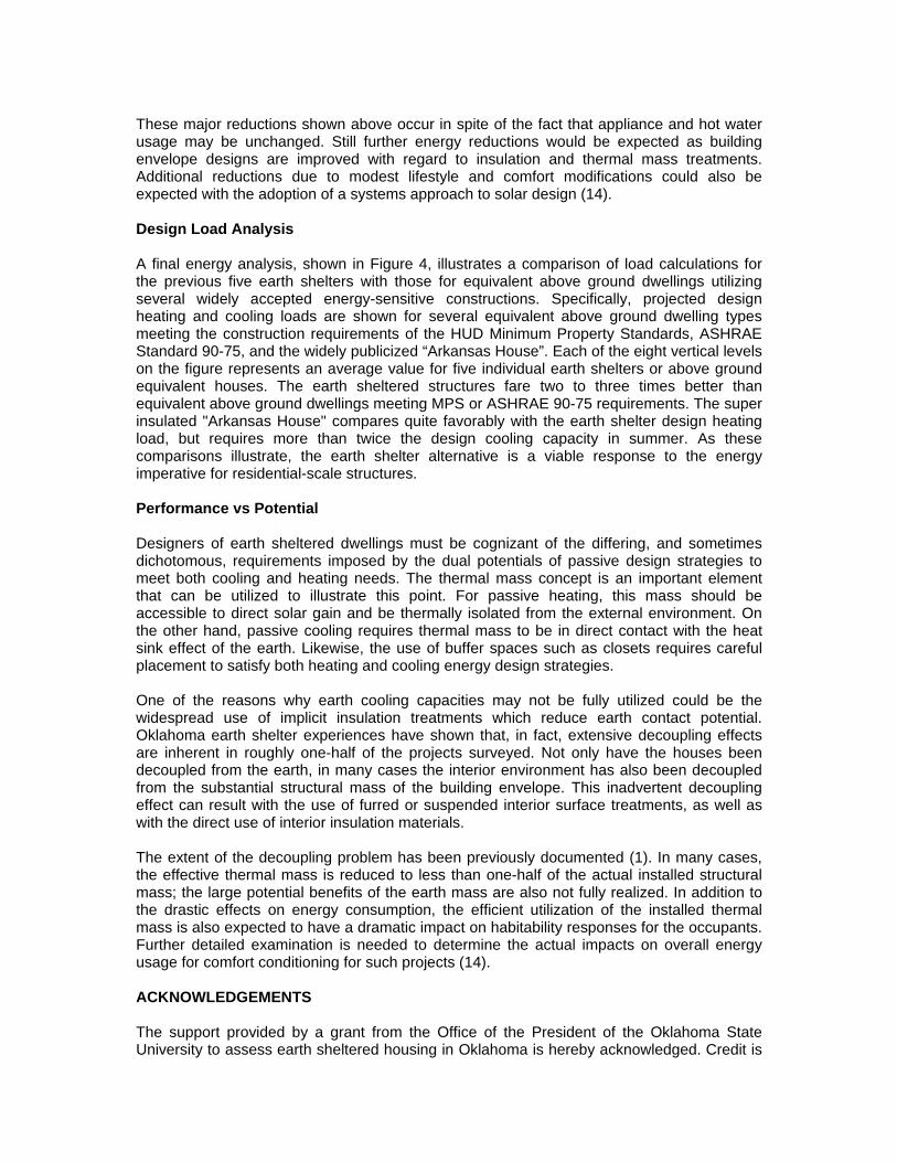
These major reductions shown above occur in spite of the fact that appliance and hot water usage may be unchanged. Still further energy reductions would be expected as building envelope designs are improved with regard to insulation and thermal mass treatments. Additional reductions due to modest lifestyle and comfort modifications could also be expected with the adoption of a systems approach to solar design (14). Design Load Analysis A final energy analysis, shown in Figure 4, illustrates a comparison of load calculations for the previous five earth shelters with those for equivalent above ground dwellings utilizing several widely accepted energy-sensitive constructions. Specifically, projected design heating and cooling loads are shown for several equivalent above ground dwelling types meeting the construction requirements of the HUD Minimum Property Standards, ASHRAE Standard 90-75, and the widely publicized “Arkansas House”. Each of the eight vertical levels on the figure represents an average value for five individual earth shelters or above ground equivalent houses. The earth sheltered structures fare two to three times better than equivalent above ground dwellings meeting MPS or ASHRAE 90-75 requirements. The super insulated "Arkansas House" compares quite favorably with the earth shelter design heating load, but requires more than twice the design cooling capacity in summer. As these comparisons illustrate, the earth shelter alternative is a viable response to the energy imperative for residential-scale structures. Performance vs Potential Designers of earth sheltered dwellings must be cognizant of the differing, and sometimes dichotomous, requirements imposed by the dual potentials of passive design strategies to meet both cooling and heating needs. The thermal mass concept is an important element that can be utilized to illustrate this point. For passive heating, this mass should be accessible to direct solar gain and be thermally isolated from the external environment. On the other hand, passive cooling requires thermal mass to be in direct contact with the heat sink effect of the earth. Likewise, the use of buffer spaces such as closets requires careful placement to satisfy both heating and cooling energy design strategies.
One of the reasons why earth cooling capacities may not be fully utilized could be the widespread use of implicit insulation treatments which reduce earth contact potential. Oklahoma earth shelter experiences have shown that, in fact, extensive decoupling effects are inherent in roughly one-half of the projects surveyed. Not only have the houses been decoupled from the earth, in many cases the interior environment has also been decoupled from the substantial structural mass of the building envelope. This inadvertent decoupling effect can result with the use of furred or suspended interior surface treatments, as well as with the direct use of interior insulation materials. The extent of the decoupling problem has been previously documented (1). In many cases, the effective thermal mass is reduced to less than one-half of the actual installed structural mass; the large potential benefits of the earth mass are also not fully realized. In addition to the drastic effects on energy consumption, the efficient utilization of the installed thermal mass is also expected to have a dramatic impact on habitability responses for the occupants. Further detailed examination is needed to determine the actual impacts on overall energy usage for comfort conditioning for such projects (14). ACKNOWLEDGEMENTS The support provided by a grant from the Office of the President of the Oklahoma State University to assess earth sheltered housing in Oklahoma is hereby acknowledged. Credit is
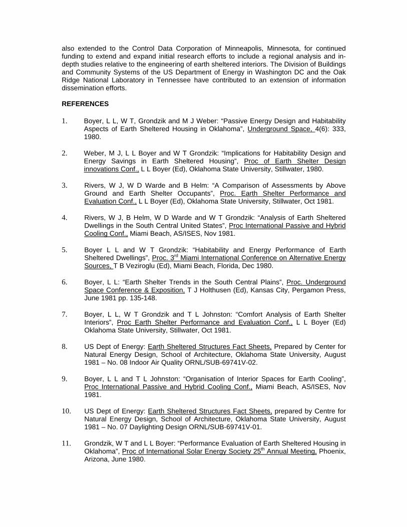
also extended to the Control Data Corporation of Minneapolis, Minnesota, for continued funding to extend and expand initial research efforts to include a regional analysis and in-depth studies relative to the engineering of earth sheltered interiors. The Division of Buildings and Community Systems of the US Department of Energy in Washington DC and the Oak Ridge National Laboratory in Tennessee have contributed to an extension of information dissemination efforts. REFERENCES 1. Boyer, L L, W T, Grondzik and M J Weber: “Passive Energy Design and Habitability
Aspects of Earth Sheltered Housing in Oklahoma”, Underground Space, 4(6): 333, 1980.
2. Weber, M J, L L Boyer and W T Grondzik: “Implications for Habitability Design and
Energy Savings in Earth Sheltered Housing”, Proc of Earth Shelter Design innovations Conf., L L Boyer (Ed), Oklahoma State University, Stillwater, 1980.
3. Rivers, W J, W D Warde and B Helm: “A Comparison of Assessments by Above
Ground and Earth Shelter Occupants”, Proc. Earth Shelter Performance and Evaluation Conf., L L Boyer (Ed), Oklahoma State University, Stillwater, Oct 1981.
4. Rivers, W J, B Helm, W D Warde and W T Grondzik: “Analysis of Earth Sheltered
Dwellings in the South Central United States”, Proc International Passive and Hybrid Cooling Conf., Miami Beach, AS/ISES, Nov 1981.
5. Boyer L L and W T Grondzik: “Habitability and Energy Performance of Earth
Sheltered Dwellings”, Proc. 3rd Miami International Conference on Alternative Energy Sources, T B Veziroglu (Ed), Miami Beach, Florida, Dec 1980.
6. Boyer, L L: “Earth Shelter Trends in the South Central Plains”, Proc. Underground
Space Conference & Exposition, T J Holthusen (Ed), Kansas City, Pergamon Press, June 1981 pp. 135-148.
7. Boyer, L L, W T Grondzik and T L Johnston: “Comfort Analysis of Earth Shelter
Interiors”, Proc Earth Shelter Performance and Evaluation Conf., L L Boyer (Ed) Oklahoma State University, Stillwater, Oct 1981.
8. US Dept of Energy: Earth Sheltered Structures Fact Sheets, Prepared by Center for
Natural Energy Design, School of Architecture, Oklahoma State University, August 1981 – No. 08 Indoor Air Quality ORNL/SUB-69741V-02.
9. Boyer, L L and T L Johnston: “Organisation of Interior Spaces for Earth Cooling”,
Proc International Passive and Hybrid Cooling Conf., Miami Beach, AS/ISES, Nov 1981.
10. US Dept of Energy: Earth Sheltered Structures Fact Sheets, prepared by Centre for
Natural Energy Design, School of Architecture, Oklahoma State University, August 1981 – No. 07 Daylighting Design ORNL/SUB-69741V-01.
11. Grondzik, W T and L L Boyer: “Performance Evaluation of Earth Sheltered Housing in
Oklahoma”, Proc of International Solar Energy Society 25th Annual Meeting, Phoenix, Arizona, June 1980.

12. Bice, T N: Energy Analysis of Earth Sheltered Dwellings, Thesis in Architectural Engineering, Oklahoma State University, Stillwater, 1980.
13. Boyer, L L, W T Grondzik and T N Bice: “Energy Usage in Earth Covered Dwellings in
Oklahoma”, Underground Space 5(4): 227, 1981. 14. Grondzik, W T., L L Boyer and J W Zang: “Analysis of Utility Billings for 55 Earth
Shelter Projects”, Proc Earth Shelter Performance and Evaluation Conf., L L Boyer (Ed), Oklahoma State University, Stillwater, Oct 1981.
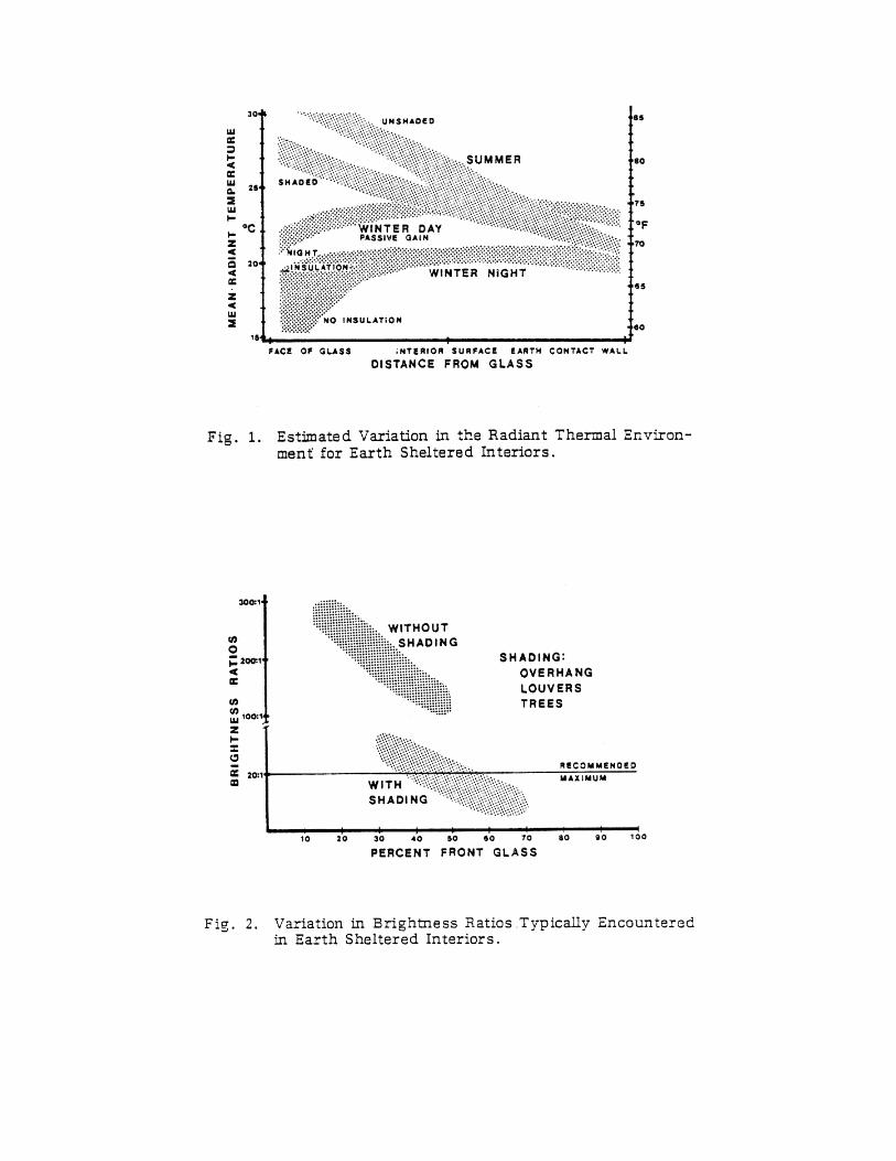
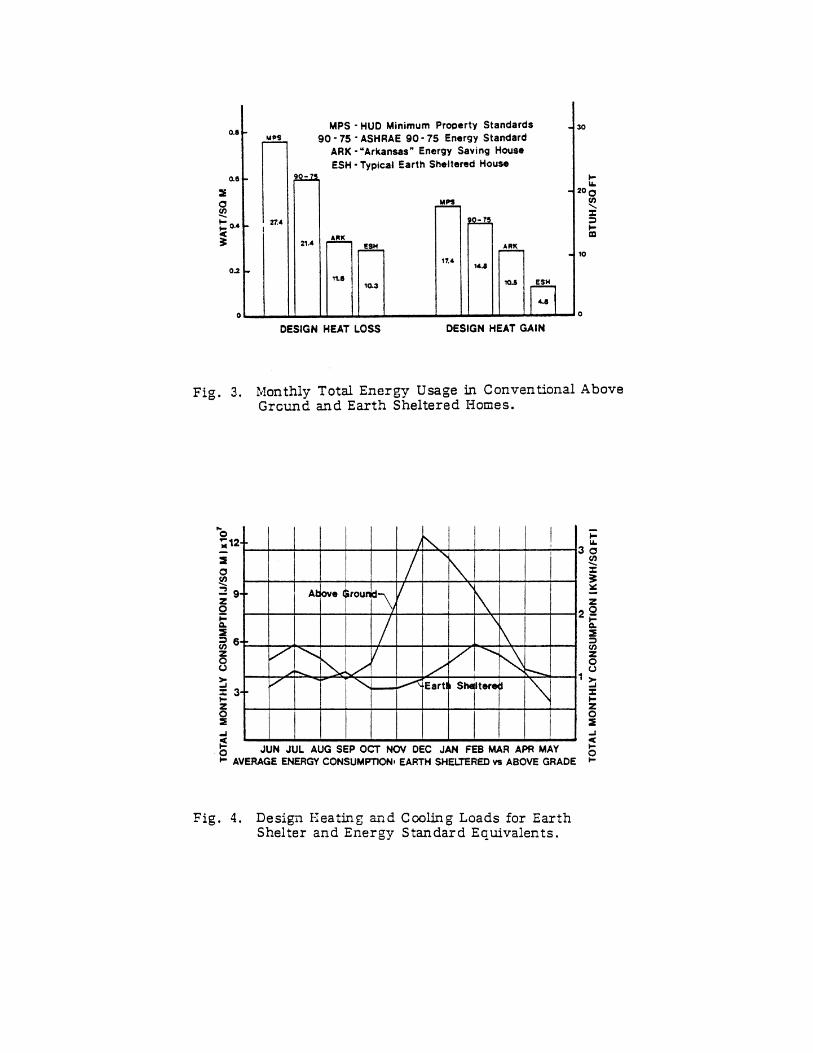
INDIRECT EARTH COOLING TECHNIQUES
James M Akridge College of Architecture
Georgia Institute of Technology Atlanta, Georgia 30322 USA
ABSTRACT Indirect or detached earth tempering may be one of the more satisfactory ways to passively cool residences, especially those located in hot-humid climates. By indirectly coupling the building to the earth, one is left with considerable freedom in how one designs the building itself. The building does not have the structural loads common to conventional earth tempered buildings, yet possess many of the thermal advantages of conventional earth tempered structures.
By indirect earth tempering we mean locating the structure itself above ground and bringing the moderate temperature environment of the ground below the surface to the above ground structure. Earth cooling tubes have been the most common means for accomplishing or attempting to attain indirect earth tempering. This paper addresses the performance of both open loop and closed loop earth cooling tubes and shows why one should not expect dramatic cooling results. The paper looks at a detached earth tempering concept under investigation at the Georgia Institute of Technology which shows significant improvement over earth cooling tubes and promises to be capable of passively supplying a significant portion of the cooling load of a well designed residence. INTRODUCTION Passive cooling has proven to be very difficult compared to passive heating, and it becomes increasingly difficult as one moves into the hot-humid regions of the world. Passive cooling techniques for hot humid regions are nonexistent. The most prevalent passive cooling technique for hot-humid regions is one of ventilation and adaptation to the uncomfortable environment. Although our study identified earth tempering as showing potential for providing some passive cooling, one cannot find indigenous architecture using earth tempering in hot-humid regions. One finds upon careful study that earth tempering in hot-humid regions has been held back not by the potential but by technical problems which were beyond our ability to solve until recently. If one looks at why one doesn't find indigenous earth tempering architecture in hot-humid regions, one discovers that there has not been a satisfactory method for handling the latent load. In many instances, the earth will provide sufficient sensible cooling, but the latent load cannot be handled passively. Relatively cool very humid air in many cases is not an improvement over hot less humid air. Humidity within a structure comes primarily from infiltration and ventilation, although some latent load comes from internal sources. This suggests that if one could control ventilation and infiltration, building loads would not be significantly different from those in less humid climates. Modern sealing techniques are certainly capable of controlling infiltration to the point were latent loads due to infiltration are almost nonexistent. Recent studies have shown that it is possible to encounter health problems if ventilation is not implemented in very tight buildings. Fortunately, if one controls building air change through ventilation one has moved the problem to a point where modern technology can address the problem of latent loads. Enthalpy exchangers are commercially available now which are capable of high (7096) latent efficiencies. One can now lower latent loads to the point where use of the earth as a tempering mechanism becomes feasible.
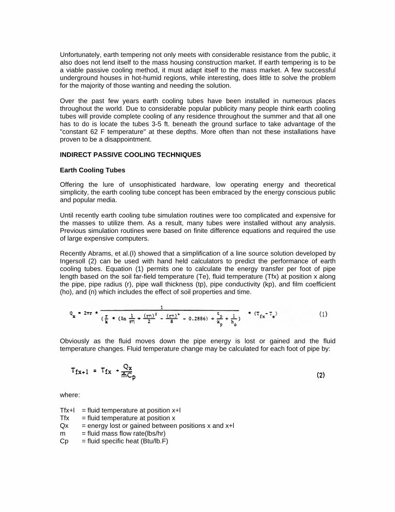
Unfortunately, earth tempering not only meets with considerable resistance from the public, it also does not lend itself to the mass housing construction market. If earth tempering is to be a viable passive cooling method, it must adapt itself to the mass market. A few successful underground houses in hot-humid regions, while interesting, does little to solve the problem for the majority of those wanting and needing the solution. Over the past few years earth cooling tubes have been installed in numerous places throughout the world. Due to considerable popular publicity many people think earth cooling tubes will provide complete cooling of any residence throughout the summer and that all one has to do is locate the tubes 3-5 ft. beneath the ground surface to take advantage of the "constant 62 F temperature" at these depths. More often than not these installations have proven to be a disappointment. INDIRECT PASSIVE COOLING TECHNIQUES Earth Cooling Tubes
Offering the lure of unsophisticated hardware, low operating energy and theoretical simplicity, the earth cooling tube concept has been embraced by the energy conscious public and popular media. Until recently earth cooling tube simulation routines were too complicated and expensive for the masses to utilize them. As a result, many tubes were installed without any analysis. Previous simulation routines were based on finite difference equations and required the use of large expensive computers.
Recently Abrams, et al.(I) showed that a simplification of a line source solution developed by Ingersoll (2) can be used with hand held calculators to predict the performance of earth cooling tubes. Equation (1) permits one to calculate the energy transfer per foot of pipe length based on the soil far-field temperature (Te), fluid temperature (Tfx) at position x along the pipe, pipe radius (r), pipe wall thickness (tp), pipe conductivity (kp), and film coefficient (ho), and (n) which includes the effect of soil properties and time.
Obviously as the fluid moves down the pipe energy is lost or gained and the fluid temperature changes. Fluid temperature change may be calculated for each foot of pipe by:
where: Tfx+l = fluid temperature at position x+l Tfx = fluid temperature at position x Qx = energy lost or gained between positions x and x+l m = fluid mass flow rate(lbs/hr) Cp = fluid specific heat (Btu/lb.F)
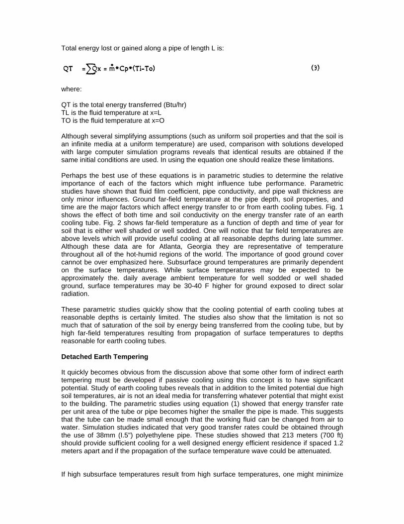
Total energy lost or gained along a pipe of length L is:
where: QT is the total energy transferred (Btu/hr) TL is the fluid temperature at x=L TO is the fluid temperature at x=O
Although several simplifying assumptions (such as uniform soil properties and that the soil is an infinite media at a uniform temperature) are used, comparison with solutions developed with large computer simulation programs reveals that identical results are obtained if the same initial conditions are used. In using the equation one should realize these limitations. Perhaps the best use of these equations is in parametric studies to determine the relative importance of each of the factors which might influence tube performance. Parametric studies have shown that fluid film coefficient, pipe conductivity, and pipe wall thickness are only minor influences. Ground far-field temperature at the pipe depth, soil properties, and time are the major factors which affect energy transfer to or from earth cooling tubes. Fig. 1 shows the effect of both time and soil conductivity on the energy transfer rate of an earth cooling tube. Fig. 2 shows far-field temperature as a function of depth and time of year for soil that is either well shaded or well sodded. One will notice that far field temperatures are above levels which will provide useful cooling at all reasonable depths during late summer. Although these data are for Atlanta, Georgia they are representative of temperature throughout all of the hot-humid regions of the world. The importance of good ground cover cannot be over emphasized here. Subsurface ground temperatures are primarily dependent on the surface temperatures. While surface temperatures may be expected to be approximately the. daily average ambient temperature for well sodded or well shaded ground, surface temperatures may be 30-40 F higher for ground exposed to direct solar radiation. These parametric studies quickly show that the cooling potential of earth cooling tubes at reasonable depths is certainly limited. The studies also show that the limitation is not so much that of saturation of the soil by energy being transferred from the cooling tube, but by high far-field temperatures resulting from propagation of surface temperatures to depths reasonable for earth cooling tubes. Detached Earth Tempering
It quickly becomes obvious from the discussion above that some other form of indirect earth tempering must be developed if passive cooling using this concept is to have significant potential. Study of earth cooling tubes reveals that in addition to the limited potential due high soil temperatures, air is not an ideal media for transferring whatever potential that might exist to the building. The parametric studies using equation (1) showed that energy transfer rate per unit area of the tube or pipe becomes higher the smaller the pipe is made. This suggests that the tube can be made small enough that the working fluid can be changed from air to water. Simulation studies indicated that very good transfer rates could be obtained through the use of 38mm (I.5") polyethylene pipe. These studies showed that 213 meters (700 ft) should provide sufficient cooling for a well designed energy efficient residence if spaced 1.2 meters apart and if the propagation of the surface temperature wave could be attenuated.
If high subsurface temperatures result from high surface temperatures, one might minimize
the effect by separating the surface from lower depths through the use of insulation. Unfortunately, insulation of the soil from the surface also greatly reduces the rate at which energy can be lost from the ground to the surface during the winter months when it is desirable to cool the soil beneath the surface. This means that some other means of cooling the subsurface soil must be employed during the winter months. Fig. 3 shows a Detached Earth Tempering experiment under investigation at the Georgia Institute of Technology. This field consists of 213 meters of 38mm polyethylene pipe buried at a depth of 1.2 meters, covered with .9 meters of earth followed by .51 mm of extrude polystyrene insulation. The insulation is finally covered with .3 meters of dirt with a good sod cover. The experiment is located in on open area behind the College of Architecture Building for convenience. Ideally, such a field would be located beneath a residence where it is subjected to a much milder environment.
The earth, isolated from the surface by the insulation, is cooled during the winter by passing water through an air-water heat exchanger located on the surface above the field. A simple control circuit, much like one would use with an active solar heating system, is used to turn on a small water circulation pump when the ambient temperature is below the temperature of the field at the four foot depth. The earth is thus cooled semi passively so that the energy lost to the surface during the hot months can be minimized. As stated earlier, the cooling potential is not great even if the soil temperature can be depressed significantly during the winter. This prohibits the use of a water-to-air heat exchanger to provide cool air to the residence during the summer. By embedding water coils directly in the building elements one can cool the residence through a combination of radiation and convection. This permits the system to provide cooling at much lower temperature differentials than are possible with other means of coupling the cooling potential to the residence. Fig. 4 shows how one might use internal walls with embedded coils for providing cooling to a residence with a minimum of wall space devoted to the cooling coils.
Computer simulations show that while an earth-coil system such as shown in Fig.3 should be capable of carrying the average daily cooling load of a well designed residence, it might be incapable of carrying the peak instantaneous load. This requires that the system have some inherent load leveling or storage capability. This appears to be most easily accomplished by using relatively massive walls through which the cooling coils circulate. Although there is considerable data on massive walls or floors for radiant heating, very little data are available on radiant cooling systems where the driving potential is much less than with radiant heating systems. Fig. 5 snows an experimental test room being used at Georgia Tech to determine various combinations" of wall-coil systems which will provide satisfactory cooling. Although data are just becoming available, results are encouraging. While it is important that passive heating systems be equipped with efficient backup systems, it is imperative that passive cooling systems be equipped with very efficient backup systems. It is also desirable that backup systems utilize the same or similar form of energy transfer to minimize the cost of the backup system. When the cooling field has been used until the cooling potential is too low for passive cooling, the field temperature is still ideal for a water-source heat pump. If one uses a water-to-water heat pump and adds it to the system in "the manner shown in Fig.6, one finds that the heat pump can operate with much more moderate evaporator and condenser temperatures than if used in the conventional manner. This is shown schematically on the pressure-enthalpy diagram shown in Fig.7. One finds that the efficiency of the heat pump can be increased by 6010096, i.e., the COP will increase from a maximum of 3.4 in -the conventional mode to 6.0 in the radiant mode. This permits one to use the cooling potential of the cooling field passively as long as the field temperature is low enough to provide sufficient cooling, and reposition two valves and turn on the heat pump when the field is no longer capable of meeting the load passively to switch to the very
efficient backup system. HUMIDITY CONTROL There is no passive method for controlling humidity at the present time and no promising system appears close to being a commercial product. It is imperative that humidity be controlled in a indirect coupled earth tempered building located in a hot-humid climate, not only for the sake of comfort, but to prevent problems with moisture condensation and mold and mildew. The most straight forward approach is through the use of a dehumidifier. Unfortunately, this is not a very efficient approach. Due the method of operation, conventional dehumidifiers must operate at COP's less than 1.0. Air-conditioners will operate at higher COP's, but they provide sensible cooling which could be carried passively. Fortunately, one can modify the sensible-to-latent ratio of mechanical refrigeration equipment through the addition of run-around coils as shown in Fig.8. The system shown in Fig.8 uses the energy removed from the moisture when it was condensed from the air to heat the domestic hot water. This helps solve the humidity problem while heating the domestic hot water more efficiently than it can be heated with a conventional electric resistance heater. Heat pump domestic hot water heaters are now available' from several manufacturers. If the evaporator of the heat pump DHW heater is placed inside the residence, it will heat the DHW, dehumidify the air and also cool the air. If modified with the runaround coil as shown in Fig.8, it will do more dehumidification and less sensible cooling. CONCLUSION Indirect earth tempering has potential for passively cooling well designed residences, not only in hot-humid climates, but in other hot climates as well. The approach described here is limited to those climates which have sufficiently cool winters to permit the soil to be cooled during the winter. Humidity can be controlled through the use of enthalpy exchangers, which help minimize the humidity problem, and slightly modified heat pump DHW heaters. Although the modified heat pump DHW heater is not a commercial item at the present time, only minor changes are required to conventional commercially available systems. Auxiliary backup high efficiency mechanical systems are easily adapted to the detached earth tempering concept and when slightly modified realize significant increases in efficiencies. The backup systems work through the radiant cooling walls, as in the passive mode. They also work in a similar manner in the heating mode. Earth cooling tubes show only limited potential for cooling in hot-humid climates and no potential for latent cooling due to high ground temperatures during mid and late summer in hot climates. Earth cooling tubes may provide some sensible cooling in climates which experience very cold winters and relatively mild summers, but it is doubtful that they can be cost effective. REFERENCES (1) Abrams, D.W., Akridge, J.M., and Benton, C.C., "Simulated and Measured
Performance of Earth Cooling Tubes", Proceedings of the Fifth National Solar Conference, ISES, September 1980.
(2) Innersole, L.R., Zobel, O.J., and Ingersoll, A.C., "Heat Conduction with Engineering,
Geological, and Other Applications", University of Wisconsin Press, 1954.