Embed Size (px)
Citation preview

Earth Fault Protection in Sub Transmission Systems
C O’HTesla Consultants
[email protected] Conference & Exhibition 2015, Wellington
24-26 June 2015
Abstract
The sub-transmission networks in many New Zealand distribution lines companies arechanging. Transpower is introducing neutral earthing resistors (NERs) at many Grid ExitPoints (GXPs), unearthed wind farms with significant cable networks are being embedded,and distribution companies are increasingly looking to mesh their existing and planned net-works to enhance reliability, switching flexibility, and capability.
With these changes , conventional definite time earth fault protection is not often suitableas the primary earth fault protection. The advent of numerical relaying with its event record-ing capability has helped to highlight phenomena not normally considered in the protectionliterature. Increasingly, distance and differential protection are required for the system tocoordinate effectively.
This paper covers mutual coupling between overhead circuits and how it is seen byprotection devices. It also covers the interaction of NERs with cable networks (especiallywind-farm networks), and makes comments regarding the effect of solidly earthed embed-ded generation transformers in these now ineffectively earthed sub-transmission systems.
1

1 IntroductionEarth fault protection in a solidly earthed electrical radial distribution system with delta con-nected loads is fairly simple. The connection of the phase CTs in a Holmgreen1 connectionrequires only the simplest of protection devices to detect, time and trip. Although some dis-tribution lines companies in NZ apply IDMT (or Inverse Time) to their earth fault protectiontimers, the use of definite time timers is common and makes coordination easier to arrange anddocument.
The connection of delta connected loads means any current imbalance 2 in the phases mustbe a ‘leakage’ to earth and therefore a fault has occurred and the circuit must be isolated. Whilethere are complicating factors such as very dry soils discouraging the promotion of detectablelevels of current (and the possibility of back feed earth fault via delta connections when singlephase line fusing and auto-reclosing are employed), the conventional earth fault protection basedon theHolmgreen connection of the phase CTs remains the standard choice of protection formostlines companies within their networks. In recent years, the introduction of Petersen Coil systemshas challenged the standard way of doing things and may eventually become widespread.
Radial distribution systems have worked well for many rural and suburban networks. Butright from the early days of electrical networks, planners of our urban areas have looked to createredundancy of supply through looped distribution networks and the use of the ‘transformer-feeder’ sub-transmission arrangement, often with line differential over buried pilots.
While electricity becomes even more valuable to commerce and industry, the public also be-comes more resistant to additional overhead infrastructure. With this in mind, network plannersoften look to mesh existing networks, using the same corridors to enhance capacity or reliability,sometimes leveraging off an over capacity in one part of the network to support the emergingload in another. For the purposes of this paper, the term ‘meshing’ refers to the creation of ringedor looped networks at the same voltage, that is, without transformers, and that the network isrun as a closed loop, not relying on automated or manual closure to restore supply - much likethe existing transmission system.
By comparison to radial systems, earth fault protection, when applied to meshed systems, isvulnerable to tripping for the following non fault events. Some of these scenarios are not presentwith the transmission environment.
1. Open circuits caused by mechanical stresses to overhead jumpers. (Reclose may be suc-cessful but open circuit now threatens earth fault protection.)
2. Single phase switching when paralleling feeders (Magnefix).
3. High resistance contacts within Air Break Switches.
4. Mutual Coupling from other over head networks, often under-built or adjacent circuits.
5. Tap Changers out of step on single phase transformer banks.
6. Open Delta regulators in off nominal tap when paralleling between substations.
7. Network Capacitance when the system is ineffectively earthed.
8. Non-homogeneous earthing of Transpower supply points and embedded generators.1See fig. 2 on page 52vectorial imbalance- not an open circuit
2
This paper discusses items 4, 7 and 8.
Because overhead sub-transmission networks in NZ are almost never run with aerial earthwires 3, the fault resistance is high for all types of earth faults, including insulator flash-over.Therefore sensitivity remains important in meshed networks.
Table 1 shows the expected earth fault currents for downed conductors on a variety of surface(the data for this table comes from a paper that itself acknowledges a variety of sources ofnetworks operating an different voltage). However, the table does highlight the small magnitudeof the earth fault currents and the difficulty of detecting and isolating downed conductors quickly,even in solidly earthed systems.
The point being made here is that, despite the risk of tripping from non fault conditions,sensitivity must be retained to isolate downed conductors as far as it is practical.
Surface Fault Current (A)Dry Asphalt 0Concrete(non-reinforced) 0Dry Sand 0Wet Sand 15Dry sod 20Dry grass 25Wed Sod 40Wet Grass 50Concrete(reinforced) 75
Table 1: Typical fault currents on various surfaces[7, Page 9]
1.1 Sequence DiagramsUnderstanding this papers relies on the reader having some familiarity with sequence diagrams.The theory for this is presented in many text books and papers. The author can recommendJ Lewis Blackburn’s ‘Symmetrical Components for Power Systems Engineering’[1] and theSchneider Cahier Technique ECT018 ‘Analysis of three-phase networks in disturbed operatingconditions using symmetrical components’[3].
As a brief recap, the voltage (or currents) of an unbalanced power system can be representedas the summation of three phasors, known as positive, negative and zero sequence. Conversionbetween actual values and ‘sequence’ values is described mathematically by eqs. (1) to (6) onpage 5. Va0, Va1 & Va2 are the zero, positive and negative ‘sequence’ voltages. The ‘a’ in Va
shows the angles are with respect to the A phase.For a single line to ground fault, I1 = I2 = I0 and the current flowing into the ground
is 3.I0. All conventional earth fault protection detects 3.I0. As we shall see, 3.I0 can alsobe induced into an overhead circuit making the distinction between induced currents and faultcurrent problematic.
Electrically speaking, 3.I0 is simply the summation of the phase currents from the CTs.Hence, the Holmgreen connection (see fig. 2 on page 5) is the simple and conventional wayto detect earth faults within a solidly earthed network. However 3.I2 , can only be derived,economically at least, mathematically by numerical relays.
3except for short distances as lightning protection
3

(a) Positive Sequence - the normal power system con-dition
(b) Negative Sequence - present during 2ph and 1phfaults
(c) Zero Sequence - present during 1ph faults and in-duced current
Figure 1: Positive, Negative and Zero Sequence Network
4

Va0 =1
3[Va + Vb + Vc] (1)
Va1 =1
3[Va + a.Vb + a2.Vc] (2)
Va2 =1
3[Va + a2.Vb + a.Vc] (3)
Va = Va1 + Va2 + Va0 (4)
Vb = a2.Va1 + a.Va2 + Va0 (5)
Vc = a.Va1 + a2.Va2 + Va0 (6)
where a = 1∠120 in complex notation.
1.2 Conventions in this paperThis paper contains a number of diagrams showing the zero sequence current (3.I0), causedthat flows through the ground and the zero sequence current caused by mutual induction. Toassist the reader, the current that flows in the ground and returned to the system neutrals arecoloured green. The induced zero sequence currents are coloured blue, while the induction‘Zm’ is labelled in red. The negative sequence currents are in magenta. In some diagrams, allthe currents are shown in blue but generally speaking there is no contradiction in the convention.
Figure 2: The earth fault sensisitivity of a Holmgreen connection is limited to about 6% of thephase CT under ideal conditions. [8] [9]. The NZ convention is 10-12.5% of ratio. Otherwise,a core balance CT is required to reliably detect current below this.
5

2 Mutual CouplingWhen a 3ph overhead circuit carries a single phase (or 3I0) current, the magnetic field set up byeach of the three phases no longer cancel. This magnetic field, at the fundamental frequency,is capable of inducing voltage (which can become currents) into neighbouring metallic circuitsincluding telecommunication circuits or adjacent overhead power lines. This effect can occurover hundreds of metres. Figure 3 shows picture of a typical 33kV line with an under-built 11kVcircuit. Figure 4 on the next page shows a picture of two 33kV circuits running adjacent to eachother - left most poles containing a dual circuit. Even with the road separation, the effect ofinduction is significant.
Figure 3: Underbuilt 11kV construction can induce currents into 33kV circuit above.
This effect has been considered in the transmission literature for some time (in the way itaffects distance relaying for earth faults on twin circuit towers) but it was not until the advent ofmicroprocessor relays with their fault recording ability that the effect became well recognisedwithin the sub-transmission and distribution environment. Within the transmission realm, thiseffect is commonly known as ‘mutual coupling’. Although not an especially precise term forthe kind of inter-circuit induction described here, the term has become common usage withinthe NZ industry.
As previously radial sub-transmission networks have become meshed, with the intention ofenhancing or improving reliability, this inter-circuit induction (ormutual coupling) has ironicallycaused many additional and unwanted outages. The problem has perhaps becomemore apparentin the NZ context because we tend to share multiple circuits on the same poles and we use solidor low resistance grounding instead of resonant earthing as is common in Europe.
Mutual coupling can occur between any two adjacent overhead power lines. The circuitscan be part of the same network or part of a different voltage network. For mutual coupling to
6

Figure 4: Even circuits across the road can induced currents into adjacent circuits.
become a problem, loops including two or more substations within the same voltage networkneed to be formed. If a transformer forms part a loop, generally speaking, mutual coupling isno longer an issue since there is no path for the induced current to flow. This partially explainsthe historical success of the ‘transformer- feeder’ configuration and why the effect of mutualcoupling only becomes apparent when sub-transmission buses are formed.
As a brief introduction into the nature and scope of mutual coupling, the following formulaeq. (7) was derived by a colleague during one of the earlier investigations in mutual coupling.The formula is based on a reading of Chapter 3 of Westinghouse [4]. It is an approximation butgives some insight to influence of the various parameters.
I’0 =0.001257.L.f.3I0. ln
(De
GMD
)ZoL
(7)
Where:
• I’0 = induced zero sequence current magnitude (amps)
• L = length of common coupling (km)
• f = power system frequency (hertz)
• 3I0 = residual current flowing in faulted circuit (amps)
• De = depth of ground return current (metres)
• GMD (Geometric mean distance) = equivalent conductor spacing (metres)
7
• ZoL = zero sequence impedance of the closed ring (ohms)
• De = 658.368×√R/f (metres)
Where:
• R = soil electrical resistivity (ohm . metres)
• f = power system frequency (hertz)
• For 50 hertz and 100 ohm m resistivity, De = 931 metres.
• GMD is calculated for six conductors (2 sets of 3 phase circuits) as the product of the nineunique individual conductor separation distances all raised to the power of 1/9. If eachset of 3 phase circuits was in touching trefoil, with a large circuit separation distance, theGMD is simply the circuit separation distance.
This equation should only be used for situations where the separation distance is preferablysignificantly less than 800 metres [4, Chapter 3].
What is apparent is that separation of conductors does decrease the induced currents but theeffect does not diminish as fast as one might have expected. See fig. 5 on the next page. Theinduced current is also a linear function of the loop impedance and fault current.
For the initial case investigated, the following results (see table 2) were obtained and derived:
Result induced residual current (3I0)SEL-351A relay fault data 65Digsilent model 69Hand calculation formula 68.8
Table 2: Comparison of measured and derived result
Unfortunately, the residual current flowing in the faulted circuit was not available directlyfrom the fault data (because the 11kV feeder was protected by an old electromechanical relay).The Digsilent model assumed a 4 ohm ground fault resistance.
Since this investigation, Tesla has assisted in a number of investigations that show mutualcoupling is common and in some cases the induced currents have been above the phase overcurrent protection levels. And in one case, the ‘induced’ currents induced current into a thirdcircuit with the third circuit’s earth fault protection also operating!
Figures 6 to 7 on page 10 show the induction effect in a more schematic way. Figure 6 onpage 10 shows the induction from an adjacent conductor, similar to what might occur in thecircuits emanating from a Transpower Grid Exit Point (GXP). While fig. 7 on page 10 showsthe induction that might occur from an underbuilt lower voltage circuit. The breaker highlightin red is vulnerable to tripping.
Figure 8 on page 11 shows the sequence diagram for figure 6. From here it becomes appar-ent the connected load forms an important path for the negative sequence current path. If theconnected load is rotating plant, the Z2 impedance can be much lower, increasing the currentsand affecting the relative distribution of currents.
In fig. 6 on page 10 , the zero sequence or conventional earth fault protection makes anydirectional decisions based on 3V0 voltage and the 3I0 current. The 3V0 voltage is determinedby the fault while the induced 3I0 is determined by the geometric arrangement of the mutually
8

Figure 5: The figure shows the decrease in induced current as the top circuit is moved away toright. Even at 800m, the effect in not insignficant.
9

Figure 6: Note the negative sequence algorithm point towards the source. And the 3V0 voltageis determined by the fault current and not the induced current.
Figure 7: 3V0, where it occurs, is determined by the induced voltage. In this instance, thenegative sequence current is toward the substation, the opposite of figure 6.
coupled circuits. In the figure 7, the 3V0 voltage is determined by the induced current and theZoL impedance.
The reader might also note in figure 8 that the zero sequence directional algorithm is (largely)unaffected by load but as we shall see in later sections, the zero sequence capacitance becomessignificant with the introduction of neutral earthing resistors.
2.1 Strategies for coping with mutual couplingThere are two strategies for coping with mutual coupling.
• Accept it and accept breakers will trip. Where possible, configure the system and theprotection to disconnect none or the least number of customers.
• Install and configure protection immune to its effect. This generally requires the use ofline differential protection and other unit protections.
10
Figure 8: Sequence Diagram of fault on an adjacent circuit parallel to a looped networks
11
Once the problem is understood and modelled, there are a variety of strategies that can beconsidered.
2.1.1 Limit the earth fault current
The introduction of resonant earthing or an NER will affect the amount of current induced inadjacent circuits. While a resonant system will be completely effective, an NER in the ’LowResistance’ grounding range may not be sufficient. System studies will be required.
2.1.2 Implement Fast Autoreclosing
If the breaker prone to tripping can be reclosed quickly, a system check of the voltages eitherside of opened breaker will reveal if the protection at the other end has cleared. If not, then theearth fault tripping may have been for a mutually coupled event and reclosure will be successful.The author has not seen this done though probably effective in the simplest cases.
2.1.3 Employ 3.V0 voltage checks when the system is earthed via an NER
While not effective for faults on the same voltage network, induced currents do not develop thesame level of 3.V0 as a genuine earth faults. Earth fault protection can be supervised such that the3.V0 must exceed a nominated level before tripping is allowed. This can be a useful method toavoid sub-transmission trippings/outages caused by faults on nearby transmission lines or under-built distribution circuits. It is unlikely to be a practical solution on solidly earthed systems.
2.1.4 Use Inverse Time Earth Fault Protection
Because the actual fault currents are typically much greater than the induced currents, theoret-ically, the earth fault protection could be arranged such that there is time grading between theactual and induced currents. This is probably feasible in some simple networks and where thedesigner has complete flexibility in nominating the types of earth fault protection everywhere.Often, however, the network interface will involve at least two asset owners and legacy equip-ment is often not capable. The author has not seen this done.
2.1.5 Install unit protection including line differential throughout the network
Where mutual coupling may cause an ‘N-2’ event (see section 2.1.8 on the following page),the commonly applied technical solution is to employ line differential protection on the meshednetwork and to ensure any faults that could induce apparent earth faults are cleared before anyunqualified definite time earth fault protection may operate. Because earth fault timers are nec-essarily increased or inhibited, in some instances, bus bar protection must be installed to avoidsequential clearance scenarios and much wider outages.
2.1.6 Customised directional fault guards
Requires detailed evaluation of site specific application.
12
2.1.7 Use Current polarised directional decisions
Some relays have the facility to compare the line 3.I0 current with a local transformer neutral.The provides an opportunity to discriminate between real faults and apparent faults caused bymutual coupling. Again, requires detailed evaluation of site specific application.
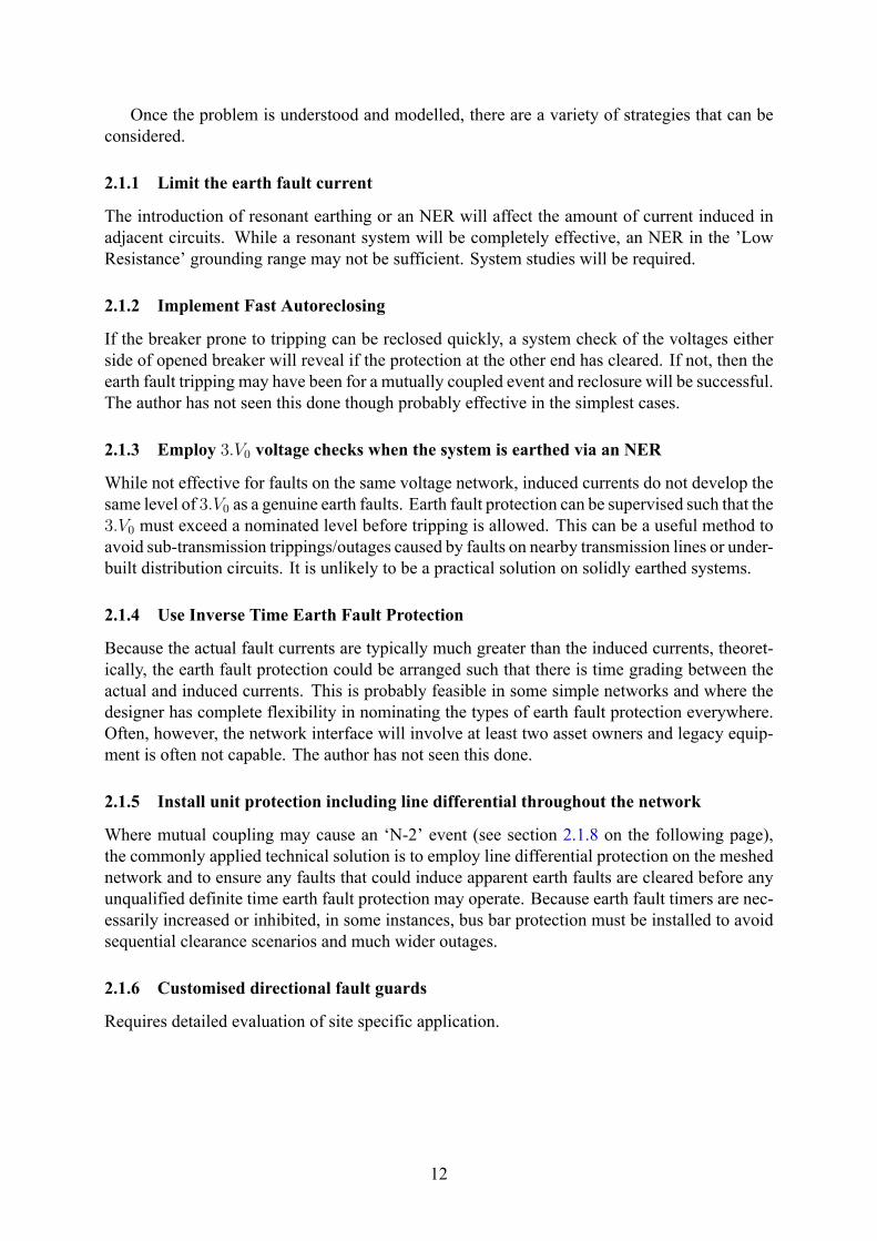
2.1.8 N-1 and N-2 reliability criteria
Useful information for plannersA common strategy to provide an alternative supply to an existing or proposed substation
is to run a circuit from an existing substation that has already has two supplies. In some casesthis may mean converting a ‘transformer-feeder’ to meshed arrangement, installing an HV buswith a closed HV bus section. See fig. 9 on the next page. If conventional directional earthfault protection is installed or retained, it will be vulnerable to tripping for induced currents.Figure 9 on the following page show that both breakers looking towards the supply (circled inmagenta) can trip for an induced current from adjacent or under-built circuits. Depending onthe load at the two substations, it may not be possible to supply the original substation from thesecond substation, either for voltage or thermal reasons. In effect, the ‘N-1’ status of the originalsubstation is compromised. The solution is likely to be installing line differential protection onboth circuits in fig. 9 on the next page.
13
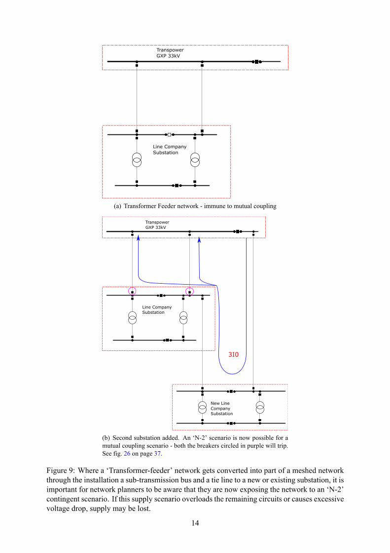
(a) Transformer Feeder network - immune to mutual coupling
(b) Second substation added. An ‘N-2’ scenario is now possible for amutual coupling scenario - both the breakers circled in purple will trip.See fig. 26 on page 37.
Figure 9: Where a ‘Transformer-feeder’ network gets converted into part of a meshed networkthrough the installation a sub-transmission bus and a tie line to a new or existing substation, it isimportant for network planners to be aware that they are now exposing the network to an ‘N-2’contingent scenario. If this supply scenario overloads the remaining circuits or causes excessivevoltage drop, supply may be lost.
14

3 Network Earthing in New ZealandThe following discussion makes reference to the common sub-transmission voltage of 33kV. Ifearthed via an NER, the following discussion is also relevant to 66 & 110kV sub-transmissionsystems.
The common types of earthing the author is aware of in the New Zealand distribution net-works are:
• Solidly Earthed by Dyn11,Dyn3, etc
• Reactance Earthed by Yyn0 - the most common 33/11kV configuration4
• Neutral Earthing Resistor (NER), with an earthing transformer if required.
• Resonant Earthing - with or without active compensation. E.g. Petersen Coil or SwedishNeutral.
The technical definition of ‘effectively earthed’ is
0 < X0/X1 < 3 (8)
0 < R0/X1 < 1 (9)
From the NZCCPTS 5 guide, the resistance of the NER resistor needs to be within eq. (10)to limit transient overvoltages. Transpower follow the same criteria in this regard (‘Ro > 2Xo
to dampen capacitive transients’).
2.X0 < R0 < Xc0 (10)
2.X0 < (3×RNER) < Xc0 (11)
So, in general terms, the more network capacitance, the lower the recommended resistanceof the neutral earthing resistor to dampen capacitive transients. For a 33kV network with asignificant cable network, say a windfarm, with say 15km of XLPE at 0.33 µF per km, is theequivalent of Xc0 = 643Ω.Two criteria sometimes chosen, not withstanding the above are:
• sizing the NER resistance to match the load of the transformer, that is the prospective earthfault current is the same as the phase current at full load; or,
• that the prospective earth fault current will be 10 times the sensitivity of the protectiondevice designed to see earth faults.
In the Transpower realm, the distribution of resistance values within the 33kV North IslandGXPs is presented in fig. 10 on the next page. This data was taken from Transpower’s DigSilentmodel. The modern and commonly applied NER value to the 33kV GXPs is 38Ω or that whichwill yield a 500A earth fault current.
Figure 11 on page 17 shows the range of prospective faults earth currents (of coursed in-fluenced by the method of earthing) and the type of protections required. Transpower’s NER
4Z0 is typically 0.5 to 1pu. Z1 is typically 0.1pu at ONAN rating5 New Zealand Committee for the Co-ordination of Power and Telecommunication Systems[6]. See also [9] [1]
15

Figure 10: The range of neutral earth resistor value used on 33kV supply buses within the NorthIsland of NZ
practice in NZ is well within the ‘Low resistance’ grounding realm and as such, the earth faultprotection used remains similar to that used for solidly earthed systems. This distinction of‘Low resistance’ is helpful when reading literature from other counties including Australia. Inthe New Zealand context, the resistances chosen have not sought to reduce the fire risk, or tomaintain supply during an earth fault.
As aside, some readers might be surprised to know that the Yyn0 with a solidly earthed11kV neutral configuration, so common in many distribution company networks does not yieldan effectively earthed network. The Z0 impedance of a Yyn0 transformer is often 0.5 pu to 1.0pu whereas the Z1 is 0.1-0.15 pu. With reference to eq. (8) on the previous page, the X0/X1 isapproximately 5-10. Figure 12 on page 18 shows the prospective healthy phase voltage rise onthese networks6.
In recent years, and for a variety of reasons, Transpower have elected to introduce NERs atthe GXPs that supply the various distribution companies. Sometimes they have been introducedas part of a transformer replacement and Transpower have elected to invert the previous delta-star configuration to put the star point on the HV side. Two earthing transformers, each withan NER have been applied to the 33kV network, since the 33kV delta winding has no neutral.At other sites, and often in conjunction with the replacement of the outdoor bus with an indoorswitchboard (ODID projects), an NER has been introduced into each of the existing transformerneutrals as part of the overall work.
The benefit to the 33kV networks are:
• Some reduction of step and touch potential
• Reduced thermal requirements of cable screen ratings
• Reduced electromechanical and thermal stress for power transformers.6When a phase to earth fault occurs on an Effectively Earthed System the phase voltages on the un-faulted
phases should not exceed 80% of the normal system phase voltage.
16

Figure 11: System Grounding and prospective fault current
• Reduced Earth Potential Rise (EPR) and induction into telecommunication equipment
• Conventional earth fault relaying equipment can be retained. 7
• Improved power quality with reduced voltage depression during earth faults.
The disadvantage to the 33kV networks are:
• Increased temporary over voltages may promote cross country faults 8 if insulation isalready damaged.
• Surge arrestors in the network may need to be replaced.
• Sensitivity, using conventional protection, to high resistance faults is reduced.
• Cable protection may require reconsideration.
When Transpower introduces an NER into a network that has solidly earthed embeddedgeneration, the embedded generator transformer become the main earthing connection to re-mote earth unless NERs are installed at the embedded generators site. Unless this is done, thebenefits of improved step and touch potential and reduced thermal stress are moot, in additionto complicating the directional earth fault relaying.
7Though we shall see in some instances, this is not quite so straight-forward.8cross country faults are two earth faults on different phases at different locations
17

Figure 12: Ground fault factor as a function ofXo/X1 forR1/X1 = 0 and R = 0 (graph accordingto IEC 60071-2). Note that Yyn transformers are not effectively earthed.
In the authors experience, applying NERs to the generation transformers is generally over-looked since three independent owners are involved and the generation company is often un-aware of the changes happening at the Transpower GXP. It is only when protection issues start tomanifest that the issue is reconsidered more seriously. However, if designers have not accountedfor the solidly earthed generation in their earth grid designs or cable screen ratings have been se-lected based much lower earth fault levels, then the issue become more serious as electrocutionand the risk of damaging cables increase.
18

4 Cable Capacitance, Windfarms and NERsA common arrangement for windfarms in NZ is to embed them directly into a distribution linecompany sub transmission network (33kV) without an interconnection transformer. This eco-nomical arrangement is often well suited to the sizing and scale of the existing network but itdoes introduce a significant amount of system capacitance. 9
Every cable has charging current. When the Va, Vb and Vc are balanced, the charging currentIa, Ib and Ic, when vectorially added, cancel. In a solidly earthed system, when Va is depressedbecause of an earth fault on an adjacent circuit, the 3.I0 current is the vectorial addition of Iband Ic (or −Ia).
When the system is ineffectively earthed and an earth fault occurs on the A phase, the sys-tem neutral is shifted. Effectively Va is subtracted from both Vb and Vc. Vb and Vc rise and theirangular separation shifts from 120 to 60. Now the 3.I0 current is three times as compared tothe solidly earthed system. In most solidly earthed distribution systems, cable capacitance isalmost never considered. Within ineffectively earthed systems, it becomes important to appre-ciate its possible effect. Equations (12) to (13) on the current page demonstrate the calculated3.I0 current.
Xc =1
j.ω.C=
1
2.π.f.C(12)
IG = 3.I0 =
√3.Vph−ph
Xc0
(13)
To calculate the cable capacitance in the absence of manufacturer data, eq. (14) can be used.
C =2πε0εR
ln(
rdordi
)F/m (14)
where:ε0 = Relative permittivity of free space is 8.854× 10⁻¹²F/mεR = Relative permittivity of the insulation material. About 4 for XLPE.rdo= Inside radius of the sheath or outside radius of the insulation, if shielding tape is used
(m).rdi = Radius of the conductor (m).In many instances this 3.I0 is greater then the conventional earth fault setting. In some cases,
the author has seen this current at over 120A on a 33kV system. This is where care is requiredwhen an NER is introduced into a system with significant cable capacitance. Effectively, everytime a low resistance earth fault occurs, the earth fault protection in the path connecting thewindfarm or significant cable circuit will pickup.
The issue becomes, how to retain sensitivity to genuine high resistance earth fault (40-60A)but avoid tripping the windfarm whenever an earth fault occurs anywhere else in the system.
In some instances, time coordination is sufficient. This is covered in more detail in sec-tion 5.2 on page 43.
Figure 14 on page 22 shows the sequence diagram of the sympathetic tripping scenario.While the Z2 impedance does not change the sensitivity, the V2 voltage is reduced by the NER.Some consideration of the standing V2 and V0 voltage is required before determining the setting.
9This new system capacitance can affect the tuning of load control plant.
19

Figure 13: Addition of voltages in an NER network[3, Figure 34 in reference]
20

The following discusses the implications on the direction algorithms. Again the discussionis in SEL10 terms but applicable to conventional directional relaying.
4.1 Directional DecisionsIn any meshed network, directional algorithms (or relays) are used to polarise both distanceand directional over-current and earth fault protection. For solidly earthed and low-resistancegrounded networks the relays use the sequence components to determined fault direction. His-torically, the zero sequence components have been easy to create from the CT and VT connec-tions but with the advent of microprocessor relays, manufacturers often provide methods basedon the negative sequence components too. Negative sequence has the advantage of being im-mune to mutual coupling but its use when mutual coupling is present is sometimes problematic.
4.1.1 NERs and Z0MTA
The following discussion describes the SEL algorithm but the same conclusions can be drawnfor other manufacturers algorithm.
The following diagram (see fig. 16 on page 25) show the effect of increasing the NER resis-tance in a network with significant cable capacitance - where 3RG = XC0S is the extreme endof the NER range. Figure 16c shows where the low resistance earthing (used by Transpower)sits on this R axis. Figure 16b shows for a conventional Z0MTA angle how the capacitancecurrent can appear forward for faults behind the relay. Figure 16d shows how with a negativeZ0MTA angle, the relay can still correctly discriminate for fault contributions from capacitivesources.
For the SEL algorithm, they recommend [5]
Z0MTA =
(arc cot
(3.RG
X0T
)+ SFA
)− 90 (15)
where SFA = 30 11
And the result is often a negativeZ0MTA setting. Many relays installed within the NZ powersystem are not capable of this setting. Two configurations where the lack of a negative Z0MTAangle may affect the system are:
• Fast Bus Blocking Schemes.
• Three Terminal Line with Blocking Schemes.
Many Fast Bus Blocking scheme have been installed within the NZ grid. In fact, it was themaloperation and subsequent investigation of one these schemes that lead to the recognition ofinter-circuit induction or mutual coupling.
4.1.2 Fast Bus Blocking Scheme (FBB)
If an NER is installed on a bus with a fast bus blocking scheme and there is sufficient cableimpedance, unless the Z0MTA angles are reconsidered, the capacitive circuit will always blockthe FBB scheme by always declaring a forward fault, regardless of the earth fault location.
10Schweitzer Engineering Laboratories11Security Factor Angle
21

Figure 14: Sequence Diagram of fault on an adjacent circuit
22

Also note that with some directional earth fault algorithms, the relay may require additionalprocessing time before making a directional decision. This needs to be factored in any FBBscheme design operating near its limit of sensitivity. Given any capacitive current is likely to beclose to the typical EF sensitivity, this processing time may be critical. Another solution maybe desensitise the FBB scheme above the maximum capacitive current experienced - given thata genuine bus fault is unlikely to have much fault impedance, this may be acceptable.
4.1.3 Three Terminal Line Blocking Scheme
Similarly, a three terminal line directional comparison schememay require special considerationsince earth faults within the three terminal line or in the windfarm will be seen as reverse to therelay connected on the windfarm side. See fig. 15. Since three terminal lines often use blockingschemes, again careful consideration of the sensitivity and/or directionalising parameters maybe required.
Figure 15: If a windfarm is part of a three terminal network within a low-resistance earthednetwork and a conventional 3.V0 or a ORDER=V directional methods is used, the earth faultprotection closest to the windfarm will see the windfarm capacitance as a reverse fault and blockregardless of the fault location (unless there is sufficient fault impedance to limit sympathetictripping).
4.1.4 NER and Negative Sequence Directional Control
Whenever an NER is used within a network, the prospective earth fault current is markedlyreduced. With reference to fig. 14 on the previous page it becomes apparent that the negativesequence voltage is very much reduced at the relaying point - possibly below the standing 3.V2
voltage on the system. If, at the limit of the desired earth fault sensitivity, there is insufficient V2
voltage, it is desirable to use V0 based method for directional control, since there is much more3.V0 voltage across the NER.
For relays that use both the V2 and V0 methods, it may be sufficient to switch algorithmswhen the negative sequence current × the source impedance is below the standing V2. Thiscould be arranged by amending the current sensitivity of V2 algorithm.
23
4.1.5 Solidly earthed embedded generators within an NER network
There aremany embedded generators installedwithin the sub-transmission system inNewZealand.Often times these were the original hydro generators that spawned the regional lines companiesuntil they were connected into the larger national grid (formerly State Hydro, NZED, ECNZ andnow Transpower). Following British convention, these generators were solidly earthed.
As Transpower has introduced NERs at their GXP substations, these embedded generatorshave often remained solidly earthed. This has had the effect of mitigating much of the benefit ofinstalling the NERs. In our example case, we show that with the Transpower transformer solidlyearthed, the fault contribution from the embedded generator is 3,858A and the Transpower trans-former 11,624A per transformer. With NERs installed at Transpower, the embedded generatorscontribution leaps to 10,373A while the Transpower transformers now contribute only 440A pertransformer. Transpower might have expected the EF level to have dropped to 1,220A with theintroduction of the NERs. The thermal stress on the Transpower transformer is partially reducedbut not to the level hoped for (the 3.I2 current remain high for earth faults) and the generationtransformers see a threefold increase!
Furthermore, these embedded generators are sometimes switched between networks. Fig-ure 17 on page 26 shows how it is important to select the correct torque angle. For a resistivelyearthed network, an Z0MTA angle of between 5−10 is desirable. Whereas Z0MTA for a solidlyearthed network would be normally be around 50 − 80. If the Transpower supply is earthedvia an NER and the solidly earthed embedded generators are switched in and out, there is noguarantee that a Z0MTA angle, that will suit both configurations, can be found. This may leadto unwanted outages as backup protection as forced to operate or a complete loss of sensitivity.
The solution here is for the embedded generator to have an NER or NERs installed. If thegeneration stations are linked via an overhead line (as they often are in run-of-the-river schemes),it may be possible to run a fully insulated aerial neutral wire to common the stations neutralsbefore connection via a single NER to earth.
24

(a) The measured zero-sequence impedance – Z0Smoves from the third to the second quadrant of theimpedance plane as the grounding resistance variesfrom zero to 3RG = XC0S [5]
(b) The conventional 32V element fails to discrimi-nate forward from reverse faults in low-impedance-grounded systems[5]
(c) The same as figure 16 b but showing the Z0 lo-cus of forward faults in a typical New Zealand based33kV subtransmission system with a 34Ω resistor[5].The R0 = 3 ∗NER.
(d) Rotating the 32V element characteristic pro-vides directional ground fault discrimination in low-impedance-grounded systems[5]
Figure 16: Z0 impedance locus for earth faults in an ineffectively earthed network
25

(a) If the Z0MTA is set to line angle in a resistivelyearthed network, neither forward or reverse faults maybe detected
(b) When the Z0MTA is increased beyond 16 degrees,capacitive faults will present as indeterminate. Thisdoes not preclude the Q algorithm making a decision
(c) When the Z0MTA is reduced to say 5 degrees, thereverse capacitive current will not be seen in reverse.
(d) If however, the system becomes solidly earthed byanother star point, say an embedded generator, neitherthe forward or reverse faults may be detected if theZ0MTA angle remains at 5 degrees.
Figure 17: The correct Z0MTA angle is important to discriminate forward and reverse faultcorrectly. Many older SEL relays have a minimum Z0MTA angle of 40 and may not be suitable(as may other relays with limited MTA angle) when an NER is installed.
26
5 Hypothetical Network - Walkthrough using DigSilentThe following walk through demonstrates the development of a hypothetical network.
The intention is show how mutual coupling puts a meshed network at risk and how theaddition of an NER at the Transpower GXP will influence the existing solidly earthed generatorand the windfarm with significant cable capacitance.
Figures 18 to 23 on pages 28–33 shows the stages. These are worked through again in moredetail in section 5.1 on page 34 in figs. 24 to 31 on pages 35–42
27

Figure 18: Initial Substation in a ‘Transformer-Feeder Arrangement’.
28

Figure 19: Adding the second substation including the mutual coupling with the embeddedgenerator connection circuit.
29

Figure 20: Adding the second substation and adding the embedded windfarm.
30
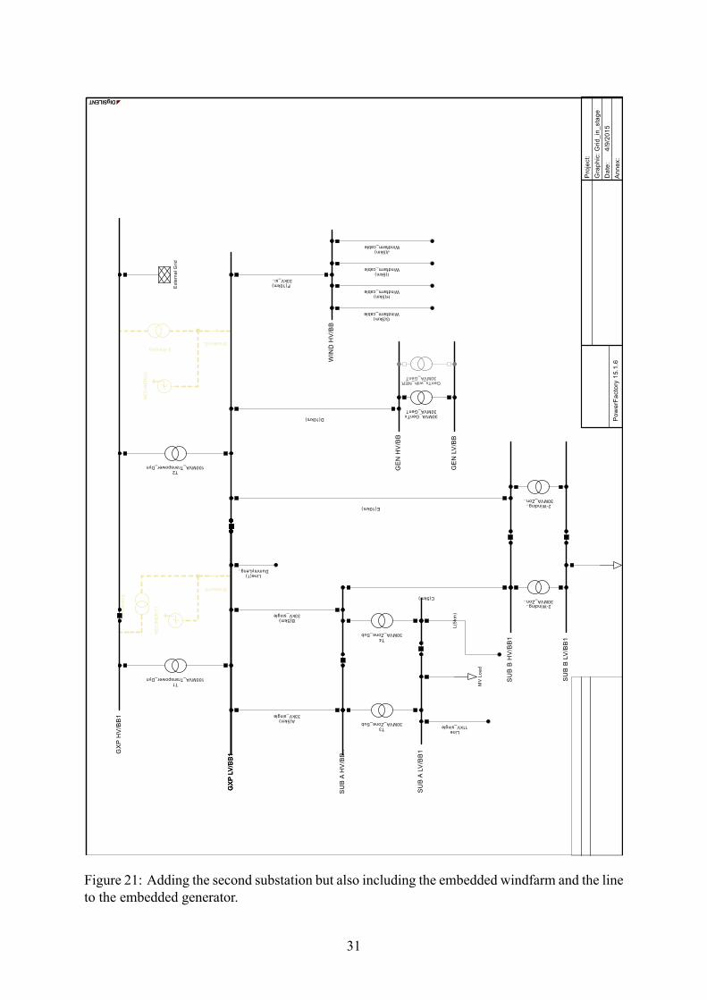
Figure 21: Adding the second substation but also including the embedded windfarm and the lineto the embedded generator.
31

Figure 22: The Transpower GXP transformer have been changed to YNd with an earthing trans-former and a 38Ω neutral earthing transformer .
32
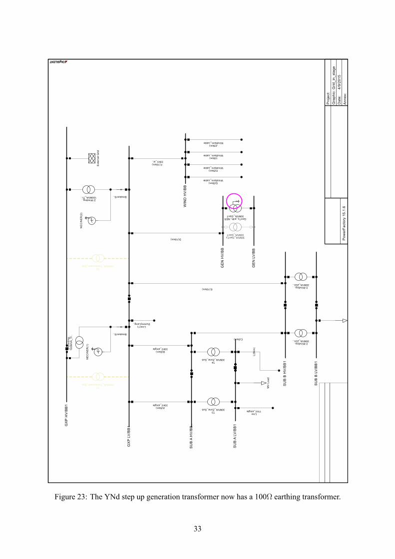
Figure 23: The YNd step up generation transformer now has a 100Ω earthing transformer.
33

5.1 Detailed worked examplesFollowing figure captions to follow what is being presented.
34

Figure 24: A transformer feeder network - immune to mutual coupling. An 11kV earth fault isplaced at the end of the 5km circuit. Note there is no 3.I0 current in the 33kV network.
35

Figure 25: The second substation is built. This same 11kV circuit is now overbuilt by the second33kV line supply to Sub B. The subtransmission system is now meshed.
36

Figure 26: When faulted, the 11kV EF can induce 631A in each of the 33kV breakers lookingtoward the source. Conventional directional earth protection will trip, leaving the SubA suppliedby SubB only. If not adequately rated, the circuit to Sub B could overload or the voltage becomeinadequate for Sub A.
37
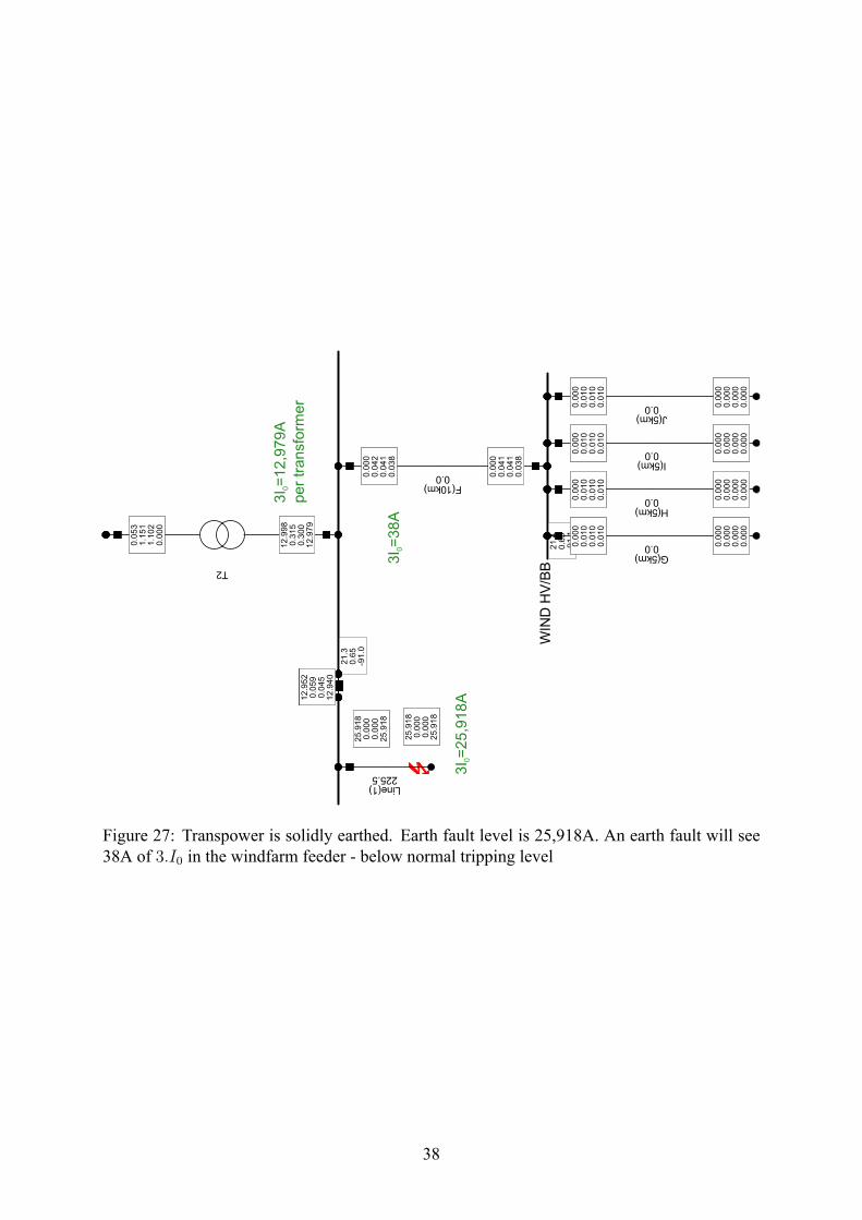
Figure 27: Transpower is solidly earthed. Earth fault level is 25,918A. An earth fault will see38A of 3.I0 in the windfarm feeder - below normal tripping level
38

Figure 28: Transpower and the embedded generator’s are solidly earthed . Earth fault level is27,070A. The embedded generators contribution is 3,858A.
39
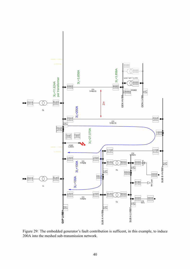
Figure 29: The embedded generator’s fault contribution is sufficent, in this example, to induce200A into the meshed sub-transmission network.
40

Figure 30: The Transpower transformers are changed to a Ynd vector group with the sameimpedance and the 33kV bus is earthed via NERs. The embedded generator contribution in-creases 3 fold to 10,373A. Despite the Transpower NERs, the Transpower transformers stillexperience 3,569A per transformer for what should have been 600A. The induction with themeshed network increases markedly with current level reaching phase overcurrent levels! Thecapacitive sympathetic earth fault current has increase to 93A- above the nominal earth faultpickup level of 60A.
41

Figure 31: The embedded generator now has an 100 ohm NER installed. The earth fault levelis now 1,414A, much closer to the anticipated design level. The generator contribution to earthfaults remains detectable and the induction into the adjacent circuit is now trivial. The step andtouch potential will be markedly improved and future cables will no longer require fully ratedscreens. Of note, the windfarm sympathetic earth level is now at its maximum at 129A. Earthfaults on the system will cause minimal voltage dip now.
42
5.2 Strategies for Sympathetic TrippingWhen directional solutions are not available time coordination can be an option. See fig. 32 onthe following page shows how a two stage definite time earth fault protection can be configuredto ensure sensitivity to genuine faults but avoid the risk of ‘sympathetic’ tripping for faults onthe adjacent circuit. See fig. 14 on page 22 for the sequence diagram. A similar effect can beachieved using inverse time over current IDMT protection. System studies would be requiredto ensure coordination with all other protection devices if IDMT is used.
43

(a) Current vs trip time
(b) Earth currents in both the faulted and adjacent circuit responding to 0 Ωand a high resistance fault at the limit of the earth fault sensitivity within a lowimpedance but ineffectively earthed network.
Figure 32: Example of using two step definite time coordination for sympathetic tripping
44

6 Neutral Voltage Displacement (NVD)and Back fed earthfaults
This section is included because NVD is the only effective means of detecting downed conduc-tors when a conductor is livened from voltage source without a neutral connection connection toground. This is a very real possibility in all ‘transformer-feeder’ networks. Some line companieswithin the industry have proposed that negative sequence current protection and line differentialprotection can detect these faults and are basing future network rationalisations on the removalof end-of-life NVD protection. This approach is not recommended especially within urban net-works.
Figures 33 to 34 on pages 45–46 shows two similar scenarios that can occur in an overheadnetwork. That is, the overhead circuit is broken and the conductor that comes into contact withthe earth is back livened from the down stream transformers.
In the case of figure 33, the downed conductor remains back livened even if the left mostcircuit breaker opens. This condition is very difficult to detect with current based protection,especially at no load and even more so with an NER installed. The only reliable means ofdetection is using neutral voltage displacement protection at the remote end (line differential isnot effective). This is sometimes done by connecting a single phase VT between the unearthedtransformer neutral and the earth grid. But the recommend approach is to use a 3 phase VTtaking care to load the VT secondary to avoid ferro resonance.
In the case of figure 34, the downed conductor is very difficult to detect without the loadremaining connected on downstream transformers. The condition is generally reported as a partpower by consumers. Unfortunately, the condition is sometimes caused by single-phase-in-linefuses blowing as part of an auto reclose sequence. The fault is cleared by one or two fusesblowing. Auto-reclosure is then successful since the earth fault protection cannot detect the oneremaining downed conductor. This scenario is usually confined to remote rural areas.
Resonant earthing systems may be able to detect this condition. Neutral displacement pro-tection, at the end of the radial feeder, has been used by at least one utility in New Zealand tomitigate this risk of very high fault resistances.
Figure 33: Neutral Voltage Displacement protection is the only kind of protection capable ofdetecting this condition without load
45

Figure 34: Consider a radial feed to a substation or substations. The earth fault current for aback fed downed conductor is dependent on the connected load. This scenario can also occurwhen single phase line fusing is installed in distribution lines.
46

6.1 Directional algorithm selectionThe following is more of an anecdote but illustrates the dynamic nature of directional algorithmscommon in many modern relays and how it can operate within a non-homogeneous network.
To paraphrase an old quote
“ Wisdom comes from experience and experience often comes from bad judge-ment ” – variously attributed .
The following example is from a relay event report kindly passed onto me from a formercolleague and is for a scheme I had designed many years ago . The scheme was a POTT schemeusingmho distance with directional comparison for high resistance earth faults and implementedusing SEL311B distance relays. There were two lines in parallel though they ran on entirely sep-arate routes. One bus was connected to a set of solidly earthed embedded generators. The otherbus was connected to the Transpower GXP via another set of parallel circuits. The TranspowerGXP was ineffectively earthed using two NERs.
At the non-embedded generator end, I decided to remove zero sequence polarising algorithmand rely entirely on Q, the negative sequence algorithm. There had been quite few trippings inprevious years due to mutually coupled under-built circuits (though the legacy relays didn’t havethe capability to prove this and mutual coupling was still a mystery to me at the time) and sowhen I did the settings, I thought using only Q might resolve this problem - Q being the newshiny thing.
Years later, an event report was sent to me showing how both circuits of the parallel line hadtripped. Both ends of the Directional Comparison Earth Fault scheme had declared forward andboth lines tripped. Because the location of the fault was known it was much simpler to focuson why the healthy circuit had tripped. Figure 35 on the following page shows the sequencenetwork.
Because the system was not homogeneously earthed, the distribution of the negative andzero sequence currents was uneven. In fact what had happened was that the fault location wasin the sweet spot of the V2 voltage being roughly equal in magnitude and phase angle. Therewas very little I2 current flowing in the healthy circuit.
With Q being the first algorithm to consider, both relays did their a2 = I2I1
> 0.1 andk2 = I2
I0> 0.2 checks. With I0 being much larger the k2 ratio wasn’t satisfied and so the relay
with ORDER=QV switched to V. The relay set with ORDER=Q couldn’t switch and, by default,discarded the k2 criteria and made a decision on Q regardless. See fig. 36 on page 49.
Because the NERs limited the Transpower (left end’s) contribution, the I0 from the solidlyearthed embedded generators goes ‘around the corner’ and so, the relay with ORDER=QVmadea forward decision on the healthy circuit, whereas the facing relay (where ORDER=Q only)made a forward decision too, based on the small amount of I2 in the circuit. If this relay had Vavailable, it would have made a reverse decision and the DCEF/POTT would not have trippedthe healthy circuit. See fig. 35 on the following page.
The lesson from the story is: if setting a Directional Comparison Earth Fault scheme with anSEL relay or another relay capable of automatic selection, ensure both ends are equipped withthe same parameters. And in regard my original concern about avoiding nuisance tripping byhaving V in the ORDER=QV equation, the very fact of having Q first in the order may wellhave resolved those concerns since any faults on the under-built 11kV circuits (supplied fromthe left bus via 33/11kV transformers) would have had the Q based algorithm seeing reverse.
47

Figure 35: SLG fault sequence diagram for midline fault within parallel lines. Transpower isearthed via an NER, while the right most generator is a solidly earthed. The supply between theTranspower source and the left most bus is somewhat simplified
48

Figure 36: An excerpt from SEL’s automatic directional algorithm selection logic
49

7 ConclusionsThe following advice is not exhaustive but may be useful to other engineers. Experts in the fieldmay form other technical opinions or preferences but where there is lack of understanding, Ihope this paper informs or at least provides a starting point for the technical issues raised.
7.1 Checklist when Transpower is installing NERs• Revisit the earthing arrangement of any embedded generators and consider installingNERs within their transformer neutrals. 12
• Determine the charging current of all cable circuits; and,
• reconsider the earth fault sensitivity; and
• reconsider the earth fault relaying angles where directional protection is applied to the thiscircuit.
• Revisit all surge arrestor ratings and replace if necessary
• While negative sequence polarising is desirable; for very strong sources with an NER, thenegative voltage generated at the limit of sensitivity may be too low. Polarising with 3.V0
will be required if other measures are not taken.
• If no NER/s are to be installed at the embedded generation sites, reconsider all earth faultprotection associated with the network.
7.2 Advice for Embedded Generators• Make plans to install NERs at all sites. If Transpower GXP changes to resistance earth-ing, the generation transformer/s will become the main contributor to earth faults on thenetwork, significantly increasing the thermal and electromechanical stress to generationplant.
7.3 Advice for Lines Companies• When NERs are installed at Transpower, all embedded generators should receive NERstoo.
• Any overhead sub-transmission circuit capable of back-feeding a fault via transformerwithout a neutral connection to ground should have Neutral Voltage Displacement, espe-cially in urban areas.
• Any windfarm or significant cable capacitance needs to be re-assessed if an NER is to beinstalled.
• Changing a network from solidly earthed to low impedance grounding may not requirenew CTs or VTs but any directional protection will need to be revisited.
• If mutual coupling is more than a nuisance, line differential protection may be required.12 Recognising a number of neutrals can be tied together before earthing at one NER.
50

• If the lines company is already considering the possibility of using resonant earthing inthe radial under-built distribution systems, the installation of a resonant earthing systemmay resolve some of mutual coupling problems.
7.4 Advice for System Planners• When re-visting a ‘transformer-feeder’ set-up, consider the possibility of mutual couplingbetween existing and proposed circuits
• When ‘N-2’ is a possibility because of mutual coupling, secure these circuits with linedifferential protection first.
• Consider fast auto reclose if line differential is too expense and/or the network can accom-modate temporary line outages with ease - i.e. maintaining voltage or temporary overloadsis not a problem.
7.5 Other commentsThe use of modern power system software such as DigSilent’s PowerFactory that can simulatemutual coupling is invaluable to verifying the currents and voltages the power system mightreasonable expect under fault conditions. Present day sub-transmission systems often have acomplex historical development. Circuits are frequently spliced and reconfigured and it cantake some effort to properly establish the potential for mutual coupling. Once modelled, theprotection designer can have some confidence in the proposed settings.
Interestingly, during my reading for this paper, I discovered a number of van Warringtonarc resistance formulas are quoted incorrectly in a number of publications, each different [6],[9], [2]. The GEC Protection and Relay Application (PRAG) guide has correctly converted theimperial units to metric from van Warrington’s original. And since it is being kept up to date,the NZCCPTS guide may need revisiting.
Lastly, thank you to my colleagues at Tesla for sharing their knowledge over the years andsponsoring my time to prepare this paper.
51

References[1] B , J. L. Symmetrical Components for Power Systems Engineering. CRC Press,
1993.
[2] C , E. Power System Protection: Systems and Methods, second ed. No. 1. PeterPeregrinus Ltd, 1981.
[3] M -N , B. Analysis of three-phase networks in disturbed operating conditionsusing symmetrical components. In Cahiers Techniques, no. 18 in 1. Schneider Electric,October 2005, p. 25.
[4] E , R. D. Electrical Transmission and Distribution Reference Book, fourth ed. No. 1 in2. Westinghouse Electric Corporation, 1964.
[5] L , R., H , D., A , H. J., F , N., C , F. Selecting DirectionalElements for Impedance-Grounded Distribution Systems. SEL (2007).
[6] O’B , M. Neutral Earthing Resistors or Reactors, 3 ed. The New Zealand Committeefor the Co-ordination of Power and Telecommunication Systems Inc., 2010.
[7] R , D. B. D. Detection of downed conductors on utility distribution systems. IEEE(1989).
[8] S . Siemens PTD EA Applications for SIPROTEC Protection Relays, 2005.
[9] W , J., Ed. Electrical Protection: Limits to Reliable Operation (2003).
52