Embed Size (px)
Citation preview
DOCUMENT RESUME
ED 092 397 SE 017 970
TITLE Earth Control and Investigations; Training Course.1974.
INSTITUTION Department of the Interior, Denver, Colo. Engineeringand Research Center.
PUB DATE Feb 74NOTE 95p.
BIAS PRICE MF-$0.75 HC-$4.20 PLUS POSTAGEDESCRIPTORS *Curriculum; *Earth Science; *EAvironmental
Education; Instruction; *Program Descriptions; SoilScience; *Teaching Guides
ABSTRACT:-
This document contains the outlines of each of 34lectUres given in the Earth Control and Investigations coursesponsored by the Denver Laboratories. Topics covered includeconstruction control of earth dams, canals, and filters; field andlaboratory test procedures; soil classification and logging; aAdfield investigations. (DT)
QS Of eauryt otT Of NE At, TM
CAJCAIIC,'%esf.t 0.21.
StOISNAL.%SSITto if Of
LDUCat ON
isk
;:f. BUREAU OF RECLAMATION
5:EM GiNfERINGAND RESEARCH
CENTER
DENVER,COLORADO
UNITED STATES
DEPARTMENT OF THE INTERIOR
BUREAU OF RECLAMATION
ENGINEERING AND RESEARCH CENTER
Denver, Colorado
EARTH CONTROL AND INVESTIGATIONS COURSE
Division of General ResearchEarth Sciences Branch
Building 56Denver Federal Center
February 4 to February IS, 1974
CONTENTS
Description of Course
Schedule of Classes 2
Instructors 6
Participants 8
Lecture Outlines 11
Conversion ractors - British to Metric Uniti of.Measurement
Organization Chart Engineering and Research Center
DESCRIPTION OP COURSE
The Earth Control and Investigations course has been given
by the Denver Laboratories during 20 of the.nast 28 years. The
course is presented by the Earth Sciences Branch of the Division
of Ceneral Research with assistance from the,Diyisionsof Design,
Construction, and Planning Coordination. The training is designed
to promote consistency and uniformity in control and investigation
procedures throughout the Bureau of Reclamation.
This.notebook contains the outlines of each lecture and space
for note taking. At the end of each outline are study references
that you should review before eael day's lectures.
On the last day, there will he a Panel discussion of any
nuestions. you would like to ask. Ouestions should he deposited in
the container at the front of the auditorium.
Three examinations will be given during the course. On Friday,
February 8, you will be tested on construction control. On Monday,
February 11, a test will he given that covers field and laboratory
test nrocedures. The last examination will be given on Friday,
February 1S, and will cover soil classification and logging and
investigations. The grades of these tests will he reported to your
nroJect or your agency and will become a permanent part of your
personnel fire: Special recognition is given to those students
with the highest grades.
1
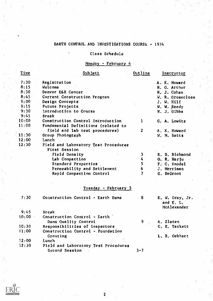
EARTH CONTROL AND INVESTIGATIONS COURSh - 1974
Class Schedule
Monday - February 4
Time Subject Outline Instructor
7:30 Registration A. K. Howard8:15 Welcome H. G. Arthur8:30 Denver E6R Center H. J. Cohan8:45 Current Construction Program W. R. Groseclose9:00 Design Concepts J. W. Hilf9:15 Future Projects W. W. Reedy9:30 Introduction to Course H. J. Gibbs9:45 Break10:00 Construction Control Introduction 1 C. A. Lowitz11:00 Fundamental Definitions (related to
field and lab test procedures) 2 A. K. Howard11:30 Group Photograph W. M. Batts12:00 Lunch12:30 Field and Laboratory Test Procedures
First SessionField Density 3 R. D. RichmondLab Compaction 4 O. R. HarjuStandard Properties 5 P. C. KnodelPermeability and Settlement 6 J. MerrimanRapid Compaction Control 7 G. DeGroot
Tuesday - February 5
7:30 Construction Control - Earth Dams
9:45 Break10:00 Construction Control - Earth
Dams Quality Control10:30 Responsibilities of Inspectors11:00 Construction Control - Foundation
Grouting12:00 Lunch12:30 Field and Laboratory Test Procedures
Second Session 3-7
E. W. Gray, Jr.and E. L.McAlexander
A. ZlatenC. E. Tackett
L. R. Cebhart
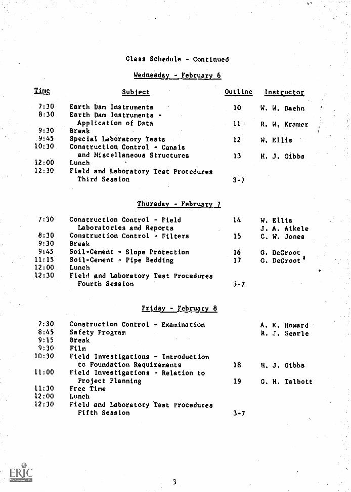
Class Schedule - Continued
Wednesday - February 6
Time Subject Outline Instructor
7:30 Earth Dam Instruments 10 W. W. Daehn8:30 Earth Dam Instruments -
Application of Data 11 R. W. Kramer9:30 Break9:45 Special Laboratory Tests 12 W. Ellis
10:30 Construction Control - Canalsand Miscellaneous Structures 13 H. J. Gibbs
12:00 Lunch12:30 Field and Laboratory Test Procedures
Third Session 3-7
Thursday - February 7
7:30 Construction Control - Field 14 W. EllisLaboratories and Reports J. A. Aikele
8:30 Construction Control - Filters 15 C. W. Jones9:30 Break9:45 Soil-Cement - Slope Protection 16 G. DeGroot11:15 Soil-Cement - Pipe Bedding 17 G. DeGroot$12:00 Lunch12:30 Field and Laboratory Test Procedures
Fourth Session 3-7
Friday - February 8
7:30 Construction Control - Examination A. K. Howard8:45 Safety Program R. J. Searle9:15 Break9:30 Film10:30 Field Investigations - Introduction
to Foundation Requirements 18 H. J. Gibbs11:00 Field Investigations - Relation to
Project Planning 19 G. H. Talbott11:30 Free Time12:00 Lunch12:30 Field and Laboratory Test Procedures
Fifth Session 3-7
3
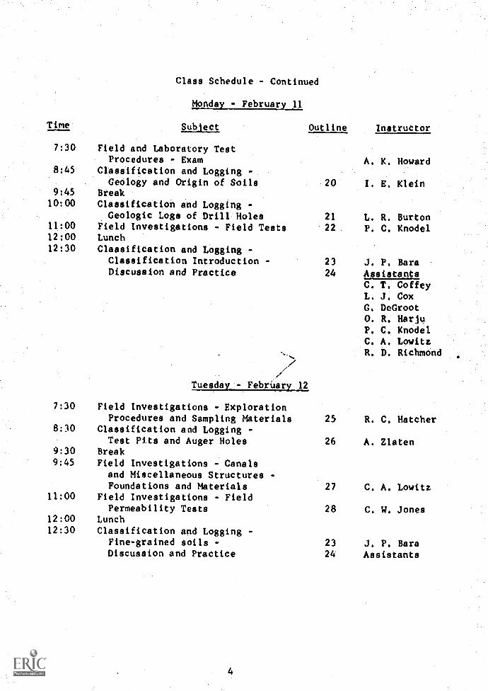
Class Schedule - Continued
Monday - February 11
Time Subject Outline Instructor
7:30 Field and Laboratory TeatProcedures - Exam A. K. Howard
8:45 Classification and Logging -Geology and Origin of Soils 20 I. E. Klein
9:45 Break
10:00 Classification and Logging -Geologic Logs of Drill Holes 21 L. R. Burton
11:00 Field Investigations - Field Tests 22 P. C. Knodel12:00 Lunch12:30 Classification and Logging -
Classification Introduction - 23 J. P. RaraDiscussion and Practice 24 Assistants
C. T. CoffeyL. J. CoxG. DeGroot0. R. MariuP. C. KnodelC. A. LowitzR. D. Richmond
Tuesday - February 12
7:30 Field Investigations - ExplorationProcedures and Sampling Materials 25 R. C. Hatcher
8:30 Classification and Logging -Test Pits and Auger Holes 26 A. Zlaten
9:30 Break9:45 Field Investigations - Canals
and Miscellaneous Structures -Foundations and Materials 27 C. A. Lowitz
11:00 Field Investigations - FieldPermeability Tests 28 C. W. Jones
12:00 Lunch12:30 Classification and Logging -
Fine- grained soils - 23 J. P. BarsDiscussion and Practice 24 Assistants
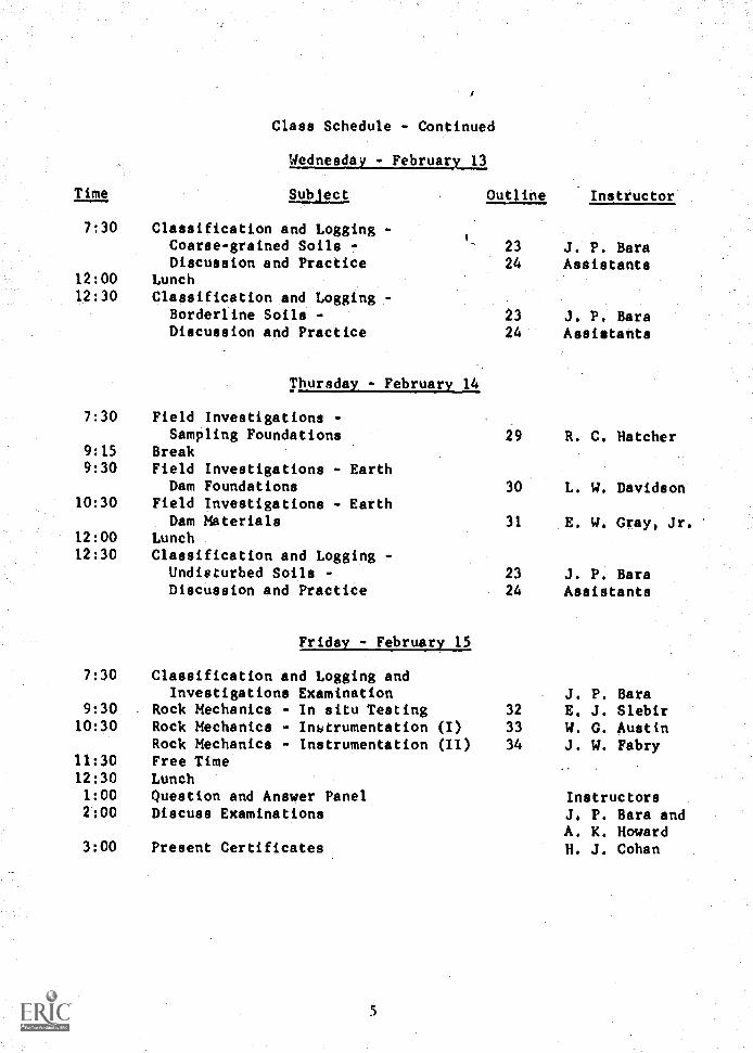
Class Schedule - Continued
Time
Wednesday - February 13
Outline InstructorSubiect
7:30 Classification and Logging -Coarse- grained Soils - 23 J. P. BarsDiscussion and Practice 24 Assistants
12:00 Lunch12:30 Classification and Logging -
Borderline Soils - 23 J. P. BarsDiscussion and Practice 24 Assistants
Thursday - February 14
7:30 Field Investigations -Sampling Foundations 29 R. C. Hatcher
9:15 Break9:30 Field Investigations - Earth
Dam Foundations 30 L. W. Davidson10:30 Field Investigations - Earth
Dam Materials 31 E. W. Gray, Jr.12:00 Lunch12:30 Classification and Logging -
Undisturbed Soils - 23 J. P. BaraDiscussion and Practice 24 Assistants
Friday - February 15
7:30 Classification and Logging andInvestigations Examination J. P. Bara
9:30 Rock Mechanics - In situ Testing 32 E. J. Slebir10:30 Rock Mechanics - Instrumentation (I) 33 W. G. Austin
Rock Mechanics - Instrumentation (II) 34 J. W. Fabry11:30 Free Time12:30 Lunch1:00 Question and Answer Panel Instructors2:00 Discuss Examinations J. P. Bara and
A. K. Howard3:00 Present Certificates H. J. Cohan
5
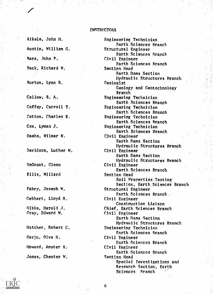
Aikele, John H.
Austin, William G.
Bara, John P.
Rock. Richard W.
Burton, Lynn R.
Callow, B. A.
Coffey, Carroll T.
Cotton, Charles E.
Cox, Lyman J.
Daehn, Wilmar W.
Davidson, Luther W.
DeGroot, Glenn
Ellis, Willard
Fabry, Joseph W.
Gebhart, Lloyd R.
Gibbs, Harold J.Gray, Edward W.
Hatcher, Robert C.
Harju, Diva R.
Howard, Amster K.
Jones, Chester W.
INSTRUCTORS
Engineering TechnicianEarth Sciences Branch
Structural EngineerEarth Sciences Branch
Civil EngineerEarth Sciences Branch
Section HeadEarth Dams SectionHydraulic Structures Branch
GeologistGeology and GeotechnologyBranch
Engineering TechnicianEarth Sciences Branch
Engineering TechnicianEarth Sciences Branch
Engineering TechnicianEarth Sciences Branch
Engineering TechnicianEarth Sciences Branch
Civil EngineerEarth Dams SectionHydraulic Structures Branch
Civil EngineerEarth Dams SectionHydraulic Structures Branch
Civil EngineerEarth Sciences Branch
Section HeadSoil Properties TestingSection, Earth Sciences Branch
Structural EngineerEarth Sciences Branch
Civil EngineerConstruction Liaison
Chief, Earth Sciences BranchCivil Engineer
Earth Dams SectionHydraulic Structures Branch
Engineering TechnicianEarth Sciences Branch
Civil EngineerEarth Sciences Branch
Civil EngineerEarth Sciences Branch
Section HeadSpec,ial Investigations andResearch Section, EarthSciences Branch --
6
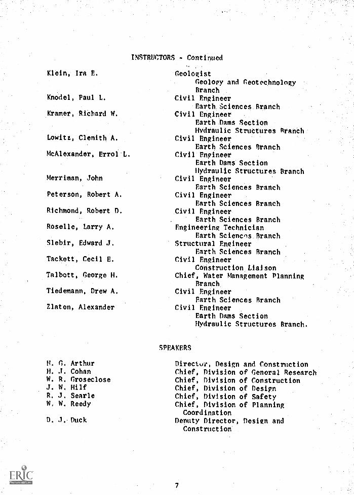
Klein, Ira P.
Knodel, Paul L.
Kramer, Richard W.
Lowitz, Clemith A.
McAlexander, Errol L.
Merriman, John
Peterson, Robert A.
Richmond, Robert D.
Roselle, Larry A.
Slebir, Edward J.
Tackett, Cecil E.
Talbott, George H.
Tiedemann, Drew A.
Zlaten, Alexander
INSTRUCTORS - Continued
GeologistGeology and GeotechnologyBranch
Civil EngineerEarth Sciences Branch
Civil EngineerEarth Dams SectionHydraulic Structures Branch
Civil EngineerEarth Sciences Branch
Civil EngineerEarth Dams SectionHydraulic Structures Branch
Civil EngineerEarth Sciences Branch
Civil EngineerEarth Sciences Branch
Civil EngineerEarth Sciences Branch
Engineering TechnicianEarth Sciences Branch
Structural EngineerEarth Sciences Branch
Civil EngineerConstruction Liaison
Chief, Water Management PlanningBranch
Civil EngineerEarth Sciences Branch
Civil EngineerEarth Dams SectionHydraulic Structures Branch.
SPEAKERS
H. G. Arthur Director, Design and ConstructionH. J. Cohan Chief, Division of General ResearchW. R. Groseclose Chief, Division of ConstructionJ. W. Hilf Chief, Division of DesignR. J. Searle Chief, Division of SafetyW. W. Reedy Chief, Division of Planning
D. 3. DuckCoordination
Deputy Director, Design andConstruction
7
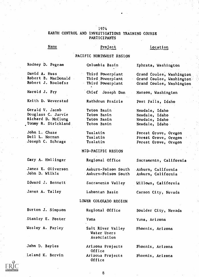
1974
EARTH CONTROL AND INVESTIGATIONS TRAINING COURSEPARTICIPANTS
Name
Rodney D. Pegram
David A. HussRobert B. MacDonaldRobert J. Roelofsz
Harold J. Fry
Keith D. Weverstad
Gerald V. JacobDouglass C. JarvieRichard D. McClungTommy R. Stricklanct
John L. ChaseDell L. NormanJoseph C. Schrage
Gary A. Hollinger
James E. OliversonJohn D. Wilkie
Edward J. Bennett
James A. Talley
Burton J. Simpson
Stanley E. Foster
Wesley A. Farley
John D. Bayles
Leland K. Bervin
Project
PACIFIC NORTHWEST REGION
Columbia Basin
Third PowerplantThirdPowerplantThird Powerplant
Chief Joseph Dam
Rathdrum Prairie
Teton BasinTeton BasinTeton BasinTeton Basin
TualatinTualatinTualatin
MID-PACIFIC REGION
Regional Office
Auburn-Folsom SouthAuburn-Folsom South
Sacramento Valley
Lahontan Basin
LOWER COLORADO REGION
Regional Office
Yuma
Salt River ValleyWater UsersAssociation
Arizona ProjectsOffice
Arizolia ProjectsOffice
Location
Ephrata, Washington
Grand Coulee WashingtonGrand Coulee, WashingtonGrand Coulee, Washington
Manson, Washington
Post Fails, Idaho
Newdale, IdahoNewdale, IdahoNewdale, IdahoNewdale, Idaho
Forest Grove, OregonForest Grove, OregonForest Grove, Oregon
Sacramento, California
Auburn, CaliforniaAuburn, California
Willows, California
Carson City, Nevada
Boulder City, Nevada
Yuma, Arizona
Phoenix, Arizona
Phoenix, Arizona
Phoenix, Arizona
LOWER COLORADO REGION - Continued-
Jesus B. Espinoza
Eugene W. Keeler
James K. Swapp
Tom Beeston
Allen R. GatesShannon L. Hebb
Edgar G. EsslingerWalter L. SanchezLeon E. Youd
David 0. AllenMac C. BaccusJ. P. BartleyOrlando R. Pacheco
Warren D. BerggrenDonald D. La RuePaul B. Larimore
Kenneth C. Hoyt
David E. Sims
Elmer D. Swarts
John W. ChapmanCharles W. DavisJohn M. Williams
John E. Crist
Theodore M. ChancellorKenneth R. Kiel
Wilson C. BevingtonDonald A. CharpentierDavid J. Davidson
Arizona ProjectsOffice
Arizona ProjectsOffice
Arizona ProjectsOffice
UPPER COLORADO REGION
Regional Office
Grand JunctionGrand Junction
Central UtahCentral UtahCentral Utah
SOUTHWEST REGION
Regional OfficeRegional OfficeRegional OfficeRegional Office
Mountain ParkMountain ParkMountain Park
Navajo IndianIrrigation
Navajo IndianIrrigation
Navajo IndianIrrigation
Palmetto BendPalmetto BendPalmetto Bend
Weslaco, Texas
UPPER MISSOURI REGION
Missouri-OaheMissouri-Oahe
Missouri-SourisMissouri-SourisMissouri-Souris
Phoenix Arizona
Phoenix, Arizona
Phoenix, Arizona
Salt Lake City, Utah
Grand Junction, ColoradoGrand Junction, Colorado
Duchesne, UtahDuchesne, UtahDuchesne, Utah
Amarillo, TexasAmarillo, TexasAmarillo, TexasAmarillo, Texas
Altus, OklahomaAltus, OklahomaAltus, Oklahoma
Farmington, New Mexico
Farmington, New Mexico
Farmington, New Mexico
Edna, TexasEdna, TexasEdna, Texas
Weslaco, Texas
Huron, South DakotaHuron, South Dakota
Bismarck, North DakotaBismarck, North DakotaBismarck, North Dakota
UPPER MISSOURI REGION Continued
Harold L. FieldMorris Pattyn
Russell E. Childers
Verlyn D. Saladen
Stanley A. GardnerDonald W. Stackhouse
James B. Kircher
Edward H. Diekmann
Stephen C. CowgillJerry D. Gilbert
RivertonRiverton
Canyon FerryDust AbatementProgram ,
Riverton WyomingRiverton, Wyoming
Great Falls, Montana
LOWER MISSOURI REGION
Regional Office Denver, Colorado
Fryingpan-Arkansas Salida, ColoradoFryingpanArkansas Salida, Colorado
Cheyenne Cheyenne, WyomingConstruction Office
ENGINEERING AND RESEARCH, CENTER:Denver, Colorado
Hydraulic Structures Branch
Geology and Geotechnology BranchGeology and Geotechnology Branch
Structural and Architectural BranchStructural and Architectural, Branch'
Kieth L. ChristiaLlenRonald D. Mohr
Charlotte A. Bechtold Applied'Sciences Branch
10
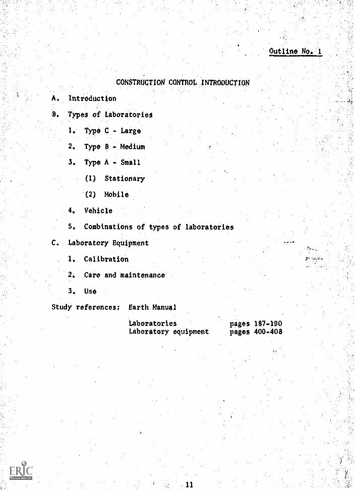
Outline No 1
CONSTRUCTION CONTROL INTRODUCTION
A. Introduction
8. Types of Laboratories
1. Type C - Large
2. Type B - Medium
3. Type A - Small
(1) Stationary
(2) Mobile
4. Vehicle
S. Combinations of types of laboratories
C. Laboratory Equipment
1. Calibration
2. Care and maintenance
3. Use
Study references: Earth Manual
Laboratories pages 187-190Laboratory equipment pages 400-408
A
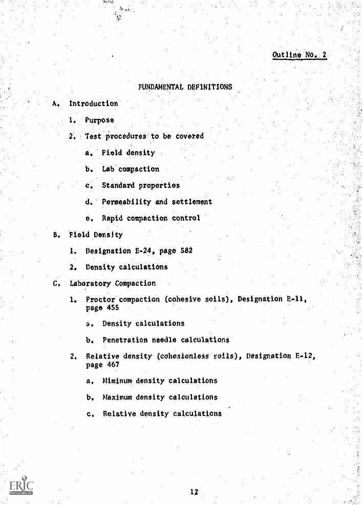
FUNDAMENTAL DEFINITIONS
Outline No. 2
A. Introduction
1. Purpose
2. Test procedures to be covered
a. Field density
b. Lab compaction
c, Standard properties
d. Permeability and settlement
e. Rapid compaction control
B. Field Density
1, Designation E-24, page 582
2. Density calculations
C. Laboratory Compaction
1, Proctor compaction (cohesive soils), Designation E-11,page 455
a. Density calculations
b. Penetration needle calculations
2. Relative density (cohesionless roils), Designation E-12,page 467
a. Miminum density calculations
b. Maximum density calculations
c. Relative density calculations
12
D. Standard Properties
1. Sample preparations, Designation E-5, page 408
2. Gradation analysis, Designation E-6, page 414
a, Sieve analysis calculations
b. Hydrometer analysis calculations
3. Soil consistency tests, Designation E-7, page 426
a. Liquid limit
b. Plastic limit
c. Shrinkage limit
d. Moisture content calculations
4. Specific gravity, Designation E-10, page 442
a. Apparent specific gravity calculations
b. Bulk specific gravity calculations
E. Permeability and Settlement
1. Soils passing No. 4 sieve, Designation E-13, page 474J
2. Soils containing gravel, Designation E-14, page 489
3. Coefficient of permeability and settlement calculations
F. Rapid Compaction Control
1. Designation E-2S, page 591
2, Calculations
G. Summary
13
Outline No. 3
FIELD AND LABORATORY TEST PROCEDURESFIELD DENSITY TEST
(Designation E-24, Earth Manual)
I. Introduction
A. Replacement methods
B. Definition
C. Uses of test
1. Construction control
2. Investigation work
D. Equipment
1. General equipment
2. Specific equipment - demonstration
3. Discussion of errors (replacement methods)
II. Test Procedure (USBR Method)
A. Preparation for test
1. Equipment
2. Control of minus NQ. 4 (fine-grained soils containinglittle or no gravel)
3. Control of minus 3-inch soils (containing appreciablegravel)
4. Calibration procedure - demonstration
B. Field procedure
1. Selection of test site
2. Preparation of area
3. Placement of template
4. Excavation of test hole
5. Measurement of volume of hole
14
C. Laboratory procedure - cohesive soils (see Earth Manual,page 586, or Drawing No. 101-D-285)
D. Laboratory procedure - cohesionless soils
III. Demonstration of Special Equipment
A. Speedy moisture meter
B. Nucliar moisture - density equipment
IV. Practical Exercise
A. Discussion of data sheets
1. 7-1425 Field Density Record
2. 7-1657 Calibration of Sand Density Test Apparatus andDensity Sand
B. Calibration of density sand - class
C. Sample calculations - field density tests
V. Summary
Study references: The following references are found in the EarthManual, Revised Edition, 1968.
1. Designation E-24, Field Density Test Pro-cedure, pages 582-591
2. Chapter III, Control of Construction,pages 248-251, page SOO
3. Practice Problem Handouts
15
Outline No. 4
FIELD AND LABORATORY TEST PROCEDURESCOMPACTION, RELATIVE DENSITY
A. Introduction - Compaction
1. Origin
2. Summary of compaction standards
a. ASTM
b. AASHO - Standard
c. AASHO - Modified
d. Corps of Engineers - Modified (airfields)
e. USBR - Large scale
f. USBR - Standard
3. Specifications of equipment
a. Equipment (calibration)
(1) Hand equipment
(2) Mechanical compactors
b. Soil
4. Test procedure
a. Mechanics of the test
b. Moisture determination
(1) 16 hours at 1100 C±
(2) Size sample
c. Computation and plotting
d. Source of error
16
S. Penetration resistance
a. Use of the penetrometer
b. Source of error
c. Value of the penetration resistance curve
6. Zero air voids curve
a. Significance of the curve
b. Computations - Zero air voids curve
7. Materials adaptable to compaction
a. Processing
b. Types cf curves to expect
8. Value of the compaction test
B. Introduction - Relative Density
1. Origin
2. Specifications
a. Equipment
b. Materials
3. Test procedure
a. Minimum density
b. Maximum density
4. Calculations and use of nomograph
S. Value of relative density test
Study references: Earth M4nual, Designation E-11, ProctorCompaction Test, pages 455 -467; EarthManual,; Designation E-12, Relative Densityof Cohesionless Soils, pages 467-474
17
Outline No. 5
LABORATORY TEST PROCEDURESSAMPLE PREPARATION, GRADATION,
ATTERBERG LIMITS, SPECIFIC GRAVITY
I. Presentation
A. Introduction
B. Sample preparation
1. Visual inspection and classification
2. Synthetic gradation analysis
3. Preparation of composite samples
C. Gradation test
1. Purpose and definition of terms
20 Separation of No. 4 sieve
3. Hydrometer analysis (minus No. 4 material)
4. Methanical analyiis
S. Computation and plotting
6. Interpretation of test results
D. Atterberg limits test
1. Purpose and definition of terms
2. Sample preparation
3. Liquid limit
a. One-point method
4. Plastic limit
5. Plasticity index
6. Shrinkage limit
7. Interpretation of test results
IS
E. Specific gravity test
1. Purpose and definition of terms
2. Sample preparation
3. Test procedure for minus No. 4 material
4. Test procedure for plus No, 4 material
II. Review
A. Answer student questions
B. Summarize main topics
Study references: Earth Manual, Designation E-5, Preparationof Soil Samples for Testing, pages 408-414;Designation E-6, Gradation Analysis of Soils,pages 414-426; Designation E-7, Soil Consist-ency Tests, pages 426-437; Designation E-10,Specific Gravity of Soils, Aggregate,pages 442-453
19
Outline No. 6
FIELD AND LABORATORY TEST PROCEDURESPERMEABILITY AND SETTLEMENT OF SOILS
I. Introduction
A. Types of permeability tests
B. Purpose of test
1. Determination of coefficient of permeability
2. Determination of percent consolidation
C. Principle
1. Darcy's Law
2. Ranges of permeability
3. Standard overburden loads
II. Test Procedure - Standard Test
A. Apparatus
1. Equipment
2. Calibration of constant-head tank
B. Preparation of sample
1. Data needed before test
2. Moisture
C. Placing of specimen
1. Check preparation sheet and compute data for packing
2. Check equipment
3. Ring readings
4. Placing specimen
S. No-load readings
6. Loading
20
D. Application of water to sample
1. Procedure
2. Readings
E, Sample removal
1. Final readings (loaded)
2. Rebound
3. Penetration resistance needle test
4. Moisture
III. Test Results
A. Calculations
1. Coefficient of permeability
2. Settlement due to saturation
B. Sources of error
1. Piping
2. Entrapped air and foreign matter
3. Temperature
4. Permeability of apparatus
S. Validity of Darcy's Law
C. Reporting results in L-29 report
IV. Other Laboratory Permeability Tests
A. Undisturbed samples
B. Nonloaded soil specimens
C. Soils containing gravel
21
Study references: All of the references below are contained inthe Earth Manual:
Chapter I, Section 21, pages 60-65, Per-meability; Chapter III, Section 62,pages 218 220, Permeability; DesignationE-13, pages 474-489, Permeability andSettlement of Soils; Designation E-14,pages 489-492, Permeability and Settlementof Soils Containing Gravel
22
Outline No, 7
FIELD AND LABORATORY TEST PROCEDURESRAPID COMPACTION CONTROL
A. Introduction
1. Provides a means of construction control for fine-grainedsoils which is accurate and can normally be performed in1 to 2 hours.
a. Density control - degree of compaction (percent ofmaximum dry density) is precisely determined.
b. Moisture control - difference from optimum Is'deter-mined to a satisfactory degree of accuracy.
2. Density and moisture conditions must be compared to stand-ards to confirm that the field conditions are similar tothose assumed during design.
B. Theory
1. Dry density determination based on oven moisture determi-nation which requires 16 to 24 hours.
2. Rapid method control based on relating all densities tothe wet density at fill water content.
3. Red line corrections for moisture control based on mois-ture and density characteristics of average soils. Thesecorrections are necessary since water contents added arebased on wet weights rather than dry weights.
C. Practice Problems
1, Symbols
Fill wet density (pcf) ywf
Cylinder wet density (pcf) ywc
Maximum density point of converted wet density curve(pcf) ym
Fill water content (%) wf
Optimum water content (%) wo
23
Ratio of fill dry density to maximum laboratory drydensity (Degree of Compaction) D
Ratio of fill dry density to cylinder dry density atsame water content C
Difference between optimum water content and fill watercontent worwf
2. Outline of problem method
a. Perform fill density test and screen material throughNo. 4 sieve to find fill wet density (ywf).
b. Compact material at fill water content by standardlaboratory test procedure to find cylinder wetdensity at fill water content (ywc).
c, Add 2 percent water to sample of material at fillwater content, compact by laboratory test procedure,Divide wet density by 1.02 (1 + water added expressedas a decimal) to find density at fill water content.
d. If second point has higher converted wet density,add 4 percent water and proceed as in (c.). Divideby 1.04 to obtain converted wet density.
e. If second point has lower converted wet density, allowmaterial at fill water content to dry until it has lost2 percent water. Compact and convert to density atfill water content. Divide by 0.98 to obtain convertedwet density.
f. Three points are sufficient if left and right pointshave lower converted wet densities than center point.Use Y
2-Y
4method.
g. If second point has lower converted wet density thanpoint at fill water content but is within 3 pcf, add1 percent water to soil at fill water content, compactand convert to density at fill water content. UseYI-Y
2method.
3. Example problems
a. Chart methods
(1) Y2-Y4 method used with even 2 percent moisture
spread. Letter points from left A, 8, and C.
24
Values in chart give ordinates of the maximumdensity point of the converted wet density curvefrom Point A.
(2) Y1 -Y2 method used with even 1 percent moisture
spread (eliminates need for drying Lack if con-verted wet density of point with 2 percent addedwater is lower in density but within 3 pcf ofpoint at fill water content).
(a) Number points in order in which they wererun (i.e., Point (1) at fill water content,Point (2) with 2 percent water added,Point (3) with 1 percent water added).
(b) Values in chart give ordinates of the max-imum density point of the converted wetdensity curve from Point (1).
(c) If the ratio of Y1 /Y2 is greater than 0.38
or if the Zm obtained from the chart is lessthan -1.0, this method is not consideredapplicable. In that case, a dry back pointshould be obtained and the problem solvedby Y2-Y4 method.
b. Graphical methods - outlined on cover sheet
(1) Can be used on all problems but is more time-consuming than chart methods.
(2) Must be used if uneven moisture spread is obtained.
c. Both chart and graphical parabola methods assume thatthe compaction curve can be approximated by a parabolawhose axis is vertical.
25
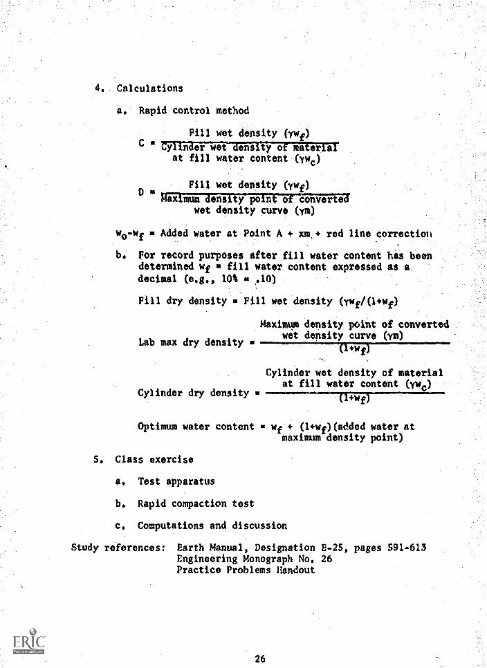
4. Calculations
a. Rapid control method
Fill wet density (iwf)C r-rrj,arTergwmrmaaeiyer%,a
at fill water content (ywc)
Pill wet density (ywf)D tr
maximum-density point of convertedwet density curve (ym)
WeWf s Added water at Point A + xm,+ red line correction
b. For record purposes after fill water content has beendetermined wf fill water content expressed as a
decimal (e.g., 10% .10)
Fill dry density Fill wet density (ywf/(1+wf)
Maximum density point of converted
Lab max dry densitywet density curve (ym)
(l+wf)
Cylinder wet density of materialat fill water content (ywc)
Cylinder dry density is
Optimum water content me wf + (l+wf)(added water atmaximum density point)
S. Class exercise
a. Test apparatus
b. Rapid compaction test
c. Computations and discussion
Study references: Earth Manual, Designation E-25, pages 591-613Engineering Monograph No. 26Practice Problems Handout
26
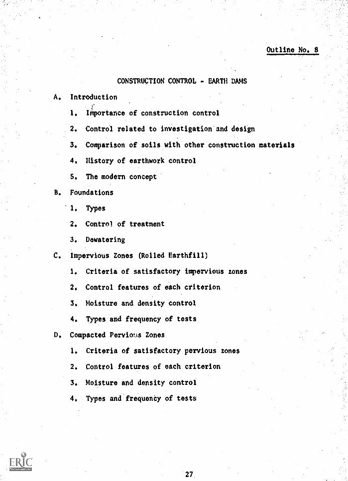
Outline No, 8
CONSTRUCTION CONTROL - EARTH DAMS
A. Introduction
1. IMportance of construction control
2. Control related to investigation and design
3. Comparison of soils with other construction materials
4. History of earthwork control
S. The modern concept
B. Foundations
1. Types
2. Control of treatment
3. Dewatering
C. Impervious Zones (Rolled Earthfill)
1. Criteria of satisfactory impervious zones
2. Control features of each criterion
3. Moisture and density control
4. Types and frequency of tests
D. Compacted Perviotis Zones
1. Criteria of satisfactory pervious zones
2. Control features of each criterion
3. Moisture and density control
4. Types and frequenCy of tests
27
E. Riprap and Rockfill
1. Criteria of satisfactory riprap and rockfill
2. Control features of each criterion
F. Summary
Study reference: Earth Manual, Chapter III, Parts A, B, C,
28
Outline No. 9
CONSTRUCTION CONTROL - EARTH DAMSQUALITY CONTROL
A. reporting Tests
1. Forms
2. Reports
B. Analysis of Field Control Tests
1. Design recommendations
2. Summary of quality control.
29
Outline No. 10
EARTH DAM INSTRUMENTATION
A. Types of Instruments and their Purpose
1. Pressure measurement apparatus pore water pressure
a. Dams
b. Structures
2. Internal movement apparatus
a. Vertical movement devices
b. Horizontal movement devices
c. Foundation settlement, baseplate devices
3. Surface measurement points
a.. Embankments
b. Structures
c. Land movements
4. Seismic apparatus
a. Accelerographs
b. Seismic - seismographs
B. Description of Apparatus
1. Twin-tube piezometers
2. Porous-tube piezometers
3. Internal movement apparatus
a. Vertical movement (crossarm) devices
b. Horizontal movement devices
4. Foundation settlement (baseplate) devices
30
S. Measurement point
a. Embankments
b. Structures
6. Seismic
a. Accelerographs and seismographs
C. Materials for Instrument Installations
1, Purchase by Government for Government installation
2. Purchase by Government for contractor's installation
3. Purchase and installation by contractor
D. Installation of equipment by
1. Government forces
2. Contract specifications
a. Prime contract
b. Special contract or extra work order
c. Supplemental contract
E. Reports Required on Installations
1. During construction - progress report - monthly - L-15 .
2. At completion of construction L-16
3, At scheduled intervals - periodic
F. Quality of Data Obtained
-1. Care during installation
2. Maintenance of recording apparatus
3. Possible failure of equipment
31
L-23
6. Forms Used for Reporting Data on Instrument Installations
1. 7-1346, 7-1347, 7-1348, 7-1355,and special forms
7-1355A, 7-1359, 7-1600,
H. Suggestions for Improving Apparatus
1. Field reports on malfunction of equipment
2. Field suggestions for design changes
3. Awards
Study references: Earth Manual, pages 258-264, Designations E-27to E-35
r.a
32
Outline No 11
EARTH DAM INSTRUMENTS - APPLICATION OF DATA
I. Why Instrumentation?
A. Verify design assumptions
B. Monitor structure for potentially dangerous conditions
II. Instruments and Information
A. Movements
1. Internal vertical movement (crossarm) device
2. Internal horizontal movement device
3. Surface measurement points
4. Deflectometer
S. Foundation settlement baseplate
B. Pressures
1. Twin-tLbe piezometers
2. Porous-tube Piezometer
3. Standpipe
C. Seepage
1. Flow-measurement devices
2. Reservoir level gage
3. Pressure measurement devices in B
D. Earthquake effects
III. Examples of Applications
IV. Data Collection (more than filling out forms)
V. Summary
33
Outline No. 12
SPECIAL LABORATORY TESTS
A. Introduction
The special tests of the laboratory are described to acquaintthe field personnel with the facilities of the laboratory andhow the materials sent from the field are studied.
B. Consolidation Test
1. Purpose and, in undisturbed soils and in disturbed soils
2. General discussion of the principle
a, Load - consolidation
b. Time - consolidation
3. Sample preparation and equipment operation
4. Results obtained
S. Permeability testing
6. Use for expansion determination
C. Shear Tests
1. Purpose and use in undisturbed soils and in disturbed soils
2. General discussion of the principle
3. Equipment available and types of tests
a. Equipment: small, medium, and large
b. Special features of the equipment
c. Unconfined compression test
d. Adaptations of standard shear tests with comments onthe purpose
34
D. Earthquake Test
1. Purpose of test and applications
2. Equipment and operation
3. Evaluation of results
Study references: Earth Manual, Designation E-15
35
Outline No. 13
CONSTRUCTION CONTROL - CANALSAND MISCELLANEOUS STRUCTURES
Note: All references are to pages in the Earth Manual.
A. Introduction - Ref. Part C, pages 212-228 and Parts E and F,pages 274-325.
Purpose of this lecture is to discuss basic techniques andfundamentals for examining and controlling quality in founda-tions and miscellaneous earth structures.
B. Basic soil types and problems concerning foundations (Refer-ence: "Engineering Use Chart," Figure 8, page 23).
1. Clays - (1) firm consolidated, (2) compressible,(3) expansive
2. Silts and low plasticity clays - (1) low density and(2) dense
3. Sands and coarse-grained soils - (1) denseness and(2) permeability
4. Rock and formation material
C. Inspection of Foundations
1. Methods of inspection and engineering guidelines
2. Protection against disturbance
3. Awareness of foundation discontinuities
4. Effect of saturation - (1) collapse, (2) expansion,(3) strength loss
S. Seepage and piping
6. Piles and caisson foundations
D. Considerations for Canal Subsoils
1. Seepage
2. Erosion
3. Ground water
36
E. Consideration for Pipeline Subgrades
F. Control Criteria of Special Interest
1. Expansive clay - Reference: pages 226-227Discussion of Table 3, page 227
2. Collapsing soil - Reference: pages 222-226
a. Discussion of Figure 82, page 225
b.- New chart of density versus liquid limit
3. Other uses of the density versus liquid limit chart
a. Trends of recompacted soil
b. Soft saturated and sensitive soils
c. Experience with expansive soil - New ideas ofcontrolling by moisture content
4. Criterion for selecting well-graded backfill(References: Figure 103, page 293).
a. Variations of fines
b. Variations described in ASTM: D 1241 and our usefor surfacings and subbase.
5. Recommended relative densitiy limiting requirements forgranular material (Reference: page 313).
6. Discussion of pile-driving formulas and estimating lengthfrom penetration resistance test (Reference: pages 316-318).
7. Comment of frost action limitations (Reference: page 69).
8. Guideline for use of relative density control versusProctor compaction. Also these guidelines are related tovibratory compaction as opposed to roller compaction(Reference: page 321 and Table 5, pages 287-291).
9. Latest criteria for canal cross section (Reference: Fig -
ure 100, pages 280-281).
10. New chart for recommendations of desirable earth canallining material.
37
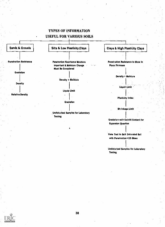
TYPES OF INFORMATION
USEFUL FOR VARIOUS SOILS
Sands & Gravels
Penetration Resistance
Gradation
Density
Relative Density
Silts & Low Plasticity Clays
Penetration Resistance Moisture
Important & Moisture ChangeMust Be Considered
Density + &failure
1
Liquid Limit
I
Gradation
Undisturbed Samples for Laboratory
Testing
t
38
Clays & High Plasticity Clays
Penetration Resistance to Show In
Place Firmness
Density 4 Moisture
Liquid Limit
Plasticity Index
Shrinkage Limit
Gradation with Colloid Content for
Expansion Question
Vane Test in Soft Saturated Soil
with Penetration <I0 Blows
Undisturbed Samples for Laboratory
Testing
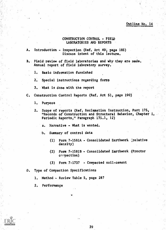
Outline No, 14
CONSTRUCTION CONTROL - FIELDLABORATORIES AND REPORTS
A. Introduction - Inspection (Ref. Art 49, page 185)Discuss intent of this lecture.
B. Field review of field laboratories and why they are made.Annual report of field laboratory survey.
1. Basic information furnished
2. Special instructions regarding forM$
3. What is done with the report
C. Construction Control Reports (Ref. Art 51, page 190)
1. Purpose
2. Scope of reports (Ref. Reclamation Instruction, Part 175,"Records of Construction and Structural Behavior, Chapter 1,Periodic Reports," Paragraph 175.1, 12)
a. Narrative - What is wanted.
b. Summary of control data
(1) Form 7-1581A - Consolidated Earthwork ',relativedensity)
(2) Form 7-1581B - Consolidated Earthwork (Proctorcm,paction)
(3) Form 7-1737 - Compacted soil-cement
D. Type of Compaction Specifications
1. Method - Review Table 5, page 287
2. Performance
11,
39
E. What We Do With Control Reports
1. Initial review of L29 reports
2. Monthly summary
3. Followup inquiries
4. Guidelines of testing frequency requirements and reworkedtests (refer to page 300)
40
Outline No. IS
CONSTRUCTION CONTROL FILTERS
A. Purpose of filters is to relieve seepage pressures in soilfoundations and structures and carry off detrimental water.
B. Uses of filters are: (a) pervious blankets or drains under-ii l linings, spillways, or dam aprons; (b) intercepting orsubsurface drains; (c) toe*drains in earth dams or levees;and (d) weighted filters on critical areas subject to seepagepressures.
C. Component parts are base materials (foundation-soils), one ormore pervious filter layers with or without open-jointed orperforated pipe.
D. General requirements are that voidssin filter be sufficientlyWin to prevent penetration by base material but sufficientlylarge and interconnected to readily transmit seepage water.Pipe joints or perforations small enough to prevent infiltrationof filter material.
E. Filter criteria are based on results of laboratory filtration,tests on typical base and filter materials. USSR filter tests(including preliminary tests on crushed rock) described inreport in EM-425 (1955).
F. Selection of filter material is based primarily on grading ofTITIW7iiierial in relation to grading of baSe material. Forthis purpose certain percent sizes are established for use incontrolling the grading of the filter material within limitson these sizes.
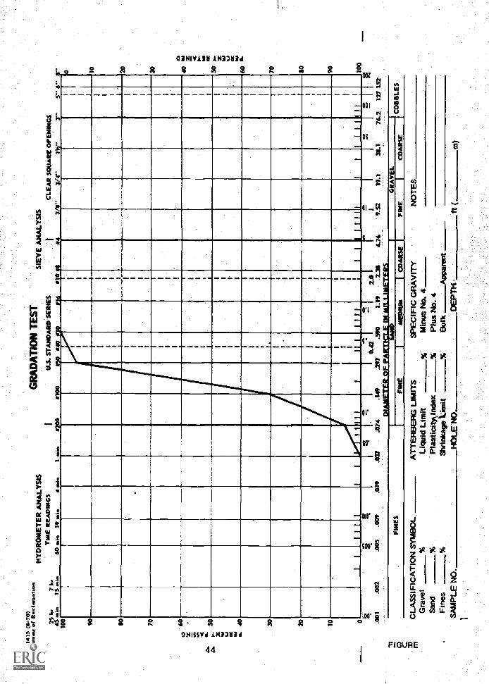
G. As an example of a given percent size the 50 percent size isshown on the standard gradation test sheet as the particlesize (abscissa), corresponding to the point where the gradingcurve intersects the 50 percent finer line of the ordinate.It is the size in a soil sample such that 50 percent by weightof the sample contains larger particles and SO percent containssmaller particles.
41
H. USBR Filter Test Criteria
1. General
a. The maximum size of material should be 3 inches.
b. Not more than 5 percent should pass the No. 200 sieve.
c. For base materials containing more than 10 percent plus.No. 4 and more than 10 percent of minus No. 200 material,the filter grading should be selected on the basis of theminus No. 4 fraction of the base material.
d. The maximum size of pipe openings or perforations shouldbe one-half the 85-percent size of the adjacent filtermaterial.
2. Natural subrounded materials
For uniform grain size filter material
50% size of filter material= 5 to 1050% size ofbase material
For graded filter materials
and
50% size of filter material12 to 5850% size of base oniarar
15% size of filter material= 12 to 4015% size abase material
3. Crushed rock (tentative criteria)
and
SO% size of filter material= 9 to 30
-3DX size o? base material
15% size of filter material= 6 to 18
15% size of base material
42
I. Construction Recommendations
1. Base material should be lightly compacted and all holes
filled.
2. Segregation of filter material should be minimized bymoistening and careful placement procedures.
3. Filter materials should be compacted,
4. Infiltration of filter material into drainpipe during
filter placement should be prevented.
Study reference: Earth Manual, pages 322.325
43
PERCENT PASSING
G. 0 4 o Sc I
.00S
NO
!
I
.
. 1
:RE I ENE 111
NI MI -
.E...111 " 11-1-111
--- --- --ME.:
all '
10 III "4
II
SO
100
o PERCENT RETAINED
3.
MM.
p
Io fll
Outline No. 16
SOIL-CEMENT SLOPE PROTECTION
A. Used as slope protection on earth dams as a substitute forrock riprap
1. Cost of slope protection can be lesS with soil-cement sincerock is scarce and costly in some areas.
2. Use of soil-cement Should be investigated if rock is morethan 20 miles away.
3. Local soils can normally be utilized with the addition of8 to 14 percent cement by dry weight of soil.
B. Historicai Background. - Soil-cement had been used extensivelyin highway work for years.
1. Bonny Test Section using two soils was constructed in 1951.
a. Mixed-in-place construction procedures were used.
b.. Soil-cement was placed in horizontal layers in a stair-step fashion up the slope.
2. Eight major Bureau of Reclamation structures have been facedwith soil-cement since 1963 using a total of 670,000 cubicyards of soil-cement.
3. In addition, the Portland Cement Association lists 62 otherstructures faced with soil-cement. Volumes of these facingsrange from 1,000 to 250,000 cubic yards.
4. Bid prices range from $5 to $12 cubic yard with most of thebids in the $6 to $9 per cubic yard range.
C. Material and Cement Content Selection
1. Gradation. - Preferred gradation is fairly well graded.
a. Well-graded materials require less cement.
b. Durability of individual grains checked by less violentdispersion action.
c. Deposits which contain lenses of clay should be avoided.
45
2. Compaction. - Material should compact to dense mass.
a. Significant increase of density at increase of cement'content may indicate use of cement to fill voids.
b. Compattion test is used as a basis for placing testspecimens.
3. Durability Tests. - Used to evaluate resistance of soil-cement to weathering - ASTM test procedures.
a. Specimens are placed similar to compaction tests,using 0.053-cubic-foot mold.
b. Specimens are used for 7 days at 100 percent humidityand 700 F (fog room curing).
c. Wet-dry tests are wetted for S hours and dried at1600 F for 43 hours.
d. Freeze-thaw tests are frozen 24 hours, thawed in fogroom for 24 hours.
e. Specimens are brushed with wire brush after each cycleand a total of 12 cycles are performed. Total loss isexpressed as a percentage.
f. Design criteria, - 6 percent max loss for wet-dry testsand 8 percent for freeze-thaw tests.
4. Compressive Strength Tests. - Used mainly as an indirectmeasure of equality.
a. Specimens are placed in 2.83- by 5.67-inch molds, 3-, 7-,28-, and 90-day tests.
b. Specimens are cured in fog room with 4- to 24-hour soak-ing period in water before testing.
c. Ends are capped with sulfur and tested at a rate of20 psi/sec.
d. Design criteria. - 600 psi minimum for 7-day specimens,875 psi minimum for 28-day specimens.
46
S. Compaction, Water Content, and Time Delay Effects
a. Increase of density usually increases quality.
b. Highest quality is usually obtained from 2 percent dryto optimum water content.
c. Due to cement-water reaction, quality decreases withtime delays; delays of 1 to 2 hours are usually not toocritical.
D. Construction Procedures
1. Material must be excavated and stockpiled in such a fashionthat a consistent material is fed to the mixer.
2. Soil and cement must be proportioned correctly prior tomixing.
a. Reciprocating plate feeder has been the most successfuldevice for soil feed.
b. Surge hopper with vane feeder is used to proportion thecement,
c. Both devices must be calibrated at start of constructionand checked occasionally.
d. Soil and cement are mixed with pugmill mixer and suffi-cient water is added during the mixing to bring theSoil - cement to the desired water content.
3. Mixed soil-cement is transported to the placement area withtrucks.
a. Soil-cement is spread to a uniform loose lift with dozer-mounted spreader.
b. Thirty-minute time limit from mixer to spreader on fill.
c. Approach ramps must be adequate to protect previouslayers.
d. Slope of up to 8:1 on placement is permitted to increaseworking width.
47
4. Material is compacted with a combination of sheepsfoot andpneumatic-tired rolling.
a. Lower portion of lift is compacted with sheepsfootroller. Roller weight is adjusted until it begins towalk out.
b. Upper portion of lift is compacted with pneumatic-tiredroller. Roller weight is adjusted until it does notcause significant lateral movement of the soil-cement.
c. Time limits between each operation are 30 minutes.
S. Curing is usually accomplished by sprinkling.
a. Use of excessive water may be detrimental.
b. Water should be applied in a fine fog-type spray.
c. Smooth compaction plane is removed by brooming andbrooming is usually repeated to clean lift for nextlayer.
E. Construction Control Procedures
1. Gradation, specific gravity, and Atterberg limits tests arerun on soil.
2. Soil and cement feed are calibrated by timing feedsseparately.
a. Soil feed is checked by timing truckload during produc-tion and using cement feed calibration to determine soilweight.
b. Cement feed is usually quite consistent in a welldesigned plant.
c. Moisture contents are determined by "quick" methods'during calibration.
3. Sample of soil-cement is obtained prior to compaction.
a. Laboratory compaction is performed at about the sametime as compaction on the placement to account for timedependency of soil-cement.
48
b. Pill density test is performed as soon as possibleafter compaction near the spot from which soil wastaken.
c. Unconfined compression specimens placed to densityfound in fill density test.
d. One test for every 500 cubic yards placed.
4. Chemical cement content determinations can be made if soilsource is low in calcium.
5. Construction control data is reported on Form No. 7-1737.
F. Record Coring
1. One core hole for every 5,000 cubic yards.
a. Unconfined compression and durability tests performedon representative pieces.
b. Comparisons with data from design tests indicate whethermaterial meets design requirements.
c. Core holes usually filled with grouted anchor bar toprovide quick reference for future inspections.
G. Portland Cement Association film "Soil-Cement Slope Protectionfor Earth Dams."
49
Outline No. 17
PLASTIC SOIL-CEMENT PIPE BEDDING
I. Introduction
A. PArst used by Bureau of Reclamation on Canadian RiverProject.
B. Conclusions of research done by American Pipe andConstruction Company.
1. The soil-cement backfill should be used only if thesoil can give adequate support for the pipe and trenchbackfill.
2. The cradle trench and soil-cement backfill eliminatelargo quantities of excavation and recompaction.
3. The soil-cement backfill provides uniform transfer ofload to the soil foundation.
4. The most suitable soil types for soil-cement are sandsand silty sand.
S. The total water requirement is a function of the per-cent fines and grain-size distribution within thematerial being used.
6. Cement requirements should be based on strength anddurability requirements for the bedding.
7. Seven-day compressive strengths of SO-psi minimum cannormally be obtained with 2 to 3 sacks of cement foreach cubic yard of bedding material.
B. Cement and water should be premixed before adding tothe soil.
9. A noncohesive soil can be mixed satisfactorily in adrum-type mixer.
II. Comparison of Bedding Methods and Materials Used
A. Conventional Bedding
1. Trench excavated to bottom of'pipe
54
2. Material placed around pipe to specified depth
a. Consolidated to 70 percent relative densityfor free-draining material
h. Compacted to 95 percent of Proctor maximumdry density for fine-grained material
3. This method often requires considerable labor.
B. Plastic Soil-cement Pipe Bedding
1. Trench excavated to depth corresponding to top ofbedding - springline elevation. (Depth of bedding
depends on design of pipe.)
2. Remainder of trench is excavated as semicircularsection 4 to 6 inches greater in diameter than theoutside diameter of the pipe.
3. Pipe sections are supported about 2 inches abovethe trench bottom on sand pads.
4. Annular space filled with plastic soil-cement.
5. This method eliminates the excavation and recompactionof the block of material between the springline andbottom of the pipe. It also is a fairly mechanized
procedure.
6. Material and cement content selection
a. Unconfined strength must be high enough to trans-fer pipe load to foundation (50-psi minimumusually desired).
b. After placement and initial set, volume changeshould be fairly small.
c. After set, material should be durable throughmoisture changes.
d. Sandy Materials with less than 10 percent finesare usually suitable with about 10 percent cement
by weight.
e. Strengths over 500 psi are not desirable as beddingmight alter shape of pipe.
51
III. Field Test Section
A. Installation. - Four sections of pipe installed usingfour different soils for bedding material. Each soilhad 2-1/2 sacks of cement per cubic yard.
1. Mortar sand - fairly well-graded material with8-1/2 percent cement by weight.
2. Blow sands - uniform fine sands with 10 percentcement by weight.
3. Blow sands . uniform fine sands with 10 percentcement by weight.
4. Lean clay - medium plasticity fine-grained materialwith 11-1/2 percent cement by weight.
B. Curing. - Pipe sections left in place 7 days.
C. Measurements and Observations of Exposed BeddingMaterials.
1. Changes of diameter after exposure were small.
2. Exposed bedding showed that good contact had beenobtained.
3. All materials seemed to perform well but lab testingshowed clay material was not durable.
IV. Construction Control
A. Gradation. - Percentage fines and organic material con-trolling factors.
1. Maximum of 10 percent fines usually specified.
B. Compressive Strength. - Adequate compressive strengthto insure firm support required.
1. Companion compressive strength specimens should beformed for each 400 feet of pipe or at least twiceper shift.
a. Bedding'material should be placed withoutconsolidation.
b. Tested after 7 days curing
52
2. Some specimens should be subjected to wet-dry cyclesto determine whether they are durable,
C. Batching. Batching by weight preferred to,provide moreconsistent results.
1. Water-cement ratio maximum usually specified as 3.5.
a. Water-cement ratio must be low enough to form afluid which will maintain sand in suspension.
2. Fluidity of mix checked by timing flow from a specialfunnel.
a. Funnel has 6 inches top diameters 4-1/2 incheshigh with 11/16-inch opening.
h. Flow time to empty funnel should be S to 8 secondsto insure that material can be pumped and willfill space completely.
V. Summary
A. Cost reduction possible due to amount of excavation andcompaction which is eliminated.
B. Should be used only if the in-place soils can give ade-quate support to the pipe.
53
Outline No. 18.
FIELD INVESTIGATIONS - INTRODUCTION TOFOUNDATION REQUIREMENTS
Note: References are to pages in the Earth Manual.
A. Introduction
Discussion of soil mechanics in investigating foundations andthe effect of foundation characteristics on the design of thestructure.
B. Basic Soil Mechanics Criteria for Analyses
1. Settlement must be within allowable limits.
2. Foundations must be safe against shear failure.
3. Specialized hydraulic structures require limitations inpermeability.
C. Foundation Problems
1. Exploration requirements - Reference: Figure 40, page 114;Figure 42, page 117.
2. Bearing capacity - Reference: page 212.
3. Stability - Reference: pages 213-216.
4. Permeability - Reference: pages 218-220.
D. Examples of Foundations With Respect to Soil Types. (Reference:pages 221-228.)
1. Clays
a. Firm consolidated clays
b. Compressive clays
c. Expansive clays
54
2. Silts and intermediate soils
a. Low - density deposits
b. Normal', intermediate soil characteristics
3. Sands and coarse-grained soils
a. Importance of density
b. Desirable effects of gravel
4. Solid rock foundation
E. Discussion of Criteria for Evaluating Penetration Resistance
55
Outline No. 19
FIELD INVESTIGATIONS - RELATION TO PROJECT PLANNING
A. Introduction
1. Necessity for project investigations
2. Stages of investigation: Regional or basin planning,appraisal, feasibility, preconstruction
B. Project Plan Formulation - Multiobjective Planning
1. Concepts of plans
2. Alternatives
3. Environmental considerations
4. Incremental analyses
5. Evaluating Plans
6. Cost Sharing and Repayment
C. Earth Control Investigations
1. Dams
a. Site-type relationships
b. Foundations, materials, and seepage
c. Spillway and other structural features
2. Canals, pipelines, and drains
a. Excavation materials
b. Stability, hydraulics, seepage, and lining
3. Tunnels
a. Excavation materials and construction methods
b. Pressures, support, lining
4. Structures
a. Foundations
56
D. Surveying and Mapping
1. Control topography, strip topography, fly lines
2. Uses: Land classification, layout, location of drillholes, etc.
3. Use of modern USGS quad sheets
4. Force account versus contracts
E. Explorations
1. Exploration required for each levelof investigations
2. Force account versus contracts
3. Methods of exploration
a. Surface inspection
b. Photo and remote sensor interpretation
c. Pits and trenches
d. Auger boring
e. Drilling
f. Geophysical methods - electric logging, resistivity,and seismic
Study references: Earth Manual, Chapter I, Properties of Soils;Chapter II, Investigations
57
Outline No, 20
CLASSIFICATION AND LOGGINGGEOLOGY AND ORIGIN OF SOILS
A. Introductory Remarks
1. The broad range of geologic conditions covered by the term"earth materials", or "soil,"
2. The geological services of the Bureau.
B. Weathering and Erosional Processes
C. Examples of Earth Materials and Geologic Environments Involvedin Bureau Projects: Slide talk based on several projects - com-pleted, under construction, or proposed - illustrating investi-gations and operations of borrows with various geologicbackgrounds.
D. Sources of geologic information useful for earth materialsexploration and testing.
E. Summary.
59
Outline No. 21
CLASSIFICATION AND LOGGINGGEOLOGIC LOGS OF DRILL HOLES
A. Use of Geologic Data in Engineering Operations
8. Reporting of Data
1. Purpose
2. Logs, sections, narrative
3. Standard forms
4. Ground-water levels
S. Soil classification symbols
6. Depth of exploration holes
7. Method of accomplishing exploration holes
8. Physical description of material
9. Name of material
10. Miscellaneous
60
Outline No. 22
FIELD INVESTIGATIONS - FIELD TESTS
A. Standard Field Penetration Test, Designation E-21, Earth Manual,page 574
1. Purpose of test
2. Test procedure and requirements
3. Results
4. Use of data
8. In-place Vane Shear Test, Designation 6-20, Earth Manual, page 562
1. 1 to 4 above
C. Methods for Determining In-place Density and Moisture
1. Hand methods
a. Undisturbed block, Designation E-2, Earth Manual, page 346
b. Undisturbed cylinder, Designation E-2, Earth Manual,page 346
c. Field density method, Designation E-24, Earth Manual,page 582
d. Auger method, Designation E-23, Earth Manual, page 579
2. Mechanical methods, Designation E-2, Earth Manual
a. Thin-wall drive sampleri
b. Double-tube samplers
c. Core samplers
3. Nuclear method
Study reference: Earth Manual, Designations E-2, 20, 21, 23, 24
61
Outline No 23
CLASSIFICATION AND LOGGING SOILCLASSIFICATION INTRODUCTION
A. Introduction
1. Unified system, differences from other standards
2. Importance to engineers
B. Soil Components
. 1. Size
a. Gravel (G)'
b. Sand (S)
c. Silt and clay (M and C)
d. organic (0)
2. Gradation (W or P)
3. Particle shape - Angularity
4. Moisture
C. Classification of Soils
1. Field
2. Laboratory
D. Engineering Characteristics of Soil Components
E. Soil Descriptions
F. Engineering Comparisons of Soil Groups
G. Summary
Study refere:ice: Earth Manual, pages 1-23, Designation E-3
62
Outline No. 24
CLASSIFICATION AND LOGGING CLASSIFICATION -DISCUSSION AND PRACTICE
A. Clean, Coarse-grained Soils (GW, GP, SW, SP)Study references: Earth Manual, pages 379-388, 396-397
B, Fine-grained Soils (ML, CL, OL, MLL, CH, 014 PT)Study references: Earth Manual, pages 388-394, 398-400
C. Coarse-grained Soils with Pines (GM, GC, SM, SC)
D. Borderline Soils
1. Well or poorly graded (GW-GP)
2. Gravel-sand mixture (GW-SW)
3. Clean or dirty (GP-GM)
4. Coarse or fine grained (GM-ML)
S. Silt or clay (ML -CL)
Study references: Earth Manual, pages 16-18, 387, 393, 397, 400
E. Classification of Undistrubed Samples
Study references: Earth Manual, pages 385, 394, 395Unified Soil Classification System(Supplement to the Earth Manual)
63
Outline No11
2560.0.
FIELD INVESTIGATIONS - EXPLORATION PROCEDURES
A. Introduction
B. Exploration Methods
1. Accessible methods of exploration
a. Trenching
b. Cuts.
c. Test pits.
d. AccesOble boring
e. Accessible caissons
f. Tunnels and drifts
g. Blasting
2. Nonaccessible methods of exploration
a. Auger boring (hand and power)
b. Hollow-stem auger
c. Enclosed flight auger
d. Drive-tube boring
e. Percussion (churn) drilling
f. Jetting
g. Wash boring
h. Rotary drilling
i. Continuous sampling
C. Other Indirect Methods (only mentioned)
Study reference: Earth Manual, Chapter II, pages 133-154
64
Outline No. 25 - Continued
FIELD INVESTIGATIONS - SAMPLING MATERIALS
A. Introduction - Purpose
B. Disturbed Samples - Types, shipping containers, moisture-contentdetermination and records
C. Sampling Procedure
1. Sampling from accessible holes
2. Sampling from nonaccessible holes
a. Holes smaller than 8 inches
b. Holes larger than 8 inches
3. Sampling stockpiles
D. Logging and Data
E. Sample Size Requirements
F. Shipping Instructions
Study reference: Earth Manual, Designation E-1
65
Outline No, 26'
CLASSIFICATION AND LOGGING LOGS OPTEST PITS AND AUGER HOLES .
A, Introduction
1, Definition
B. Purpose of Log
1, Structures
2. Borrow areas
C. The Log Form
'1, Percentage by volume of oversize
2. Natural density and moisture
3. Importance of soil classification
4. Description of soils in logs
D. Summary
Study reference: Earth Manual, pages 158-170
66
Outline No. 27
FIELD INVESTIGATIONS - CANALS AND MISCELLANEOUSSTRUCTURES FOUNDATIONS AND MATERIALS
A. Introduction Importance of Investigations
B. Planning Investigations
1. Review tentative plans for structures.
2. Review potential soil problems - early recognition.
3. Review local conditions, features, and performance ofsimilar construction.
4. Review previous investigation reports.
S. Degree of exploration varies with stage of investigation.
a, Investigate most serious problems first.
b. Use methods appropriate to furnishing the desiredinformation.
6. Maps - Topography, geology and soil conditions, hydrology.
C. StageS of Investigation
1. Reconnaissance - Descriptive
a. Properties based on visual classification
b. General appraisal and evaluation of subsurface
2. Feasibility - Qualitative
a. Limited exploration - properties determined by indextests.
3. Specifications - Quantitative and specific
a. Engineering properties determined for various soiltypes.
b. Sufficient exploration to establish conditions at allcritical points.
67
4. Characteristics of subsurface developed in progressivelygreater detail as work proceeds.
D. Soil Components, Properties, and Characteristics
1. Boulders and cobbles - stable, occurrence in situ improvesstability, angularity increases stability.
2. Gravel and sand - easy to compact, little affected by mois-ture, not subject to frost action. Well graded less per-vious and more stable than poorly graded.
3. Silt - unstable with increase of moisture, tendency tobecome quick. Relatively impervious, difficult to compact,highly susceptible to frost heave, easily erodible, subjectto piping.
4. Clay - cohesive strength increases with decrease in moisture.Low permeability, difficult to compact when wet, subject toexpansion and shrinkage.
S. Organic matter - undesirable.
E. Engineering Use Chart - Relative desirability of typical soilsfor engineering purposes.
1. Compacted earth canal lining - impervious, erosion resistant,stable. Relative desirability - (W -GC, GC, SW-SC, SC, SC-CL,CLI GM.
2. Structure backfill - desirability dependent upon backfillrequirements.
a. Impervious backfill impervious gravelly soils, SW-SC,SC, CL, SC-CL, SM-SC, SC-ML, etc.
b. Pervious backfill
Gil, GP, SW, SP <5 percent finesGW-GM, GW-GC, GP -GU, GP-GC <8 percent finesSW-SC and SM, require special consideration, suitabilitydependent on gradation and plasticity.
68
F. Surface Exploration - Familiarity with geologic landforms, soilsassociated with them, and potential problems.
1. Glacial areas
a. Heterogeneous - any type of soil, in almost any form,and in any proportion.
b. Hydraulic structures - sutiable design precautionsrequired.
c. Light structures - no difficulty.
d. Heavy structures - differential, settlement.
2. Loessial areas
a. Settlement upon wetting
b. Piping
c. Recompaction . reliable platform for footings
d. Vertical slopes
3. Sand-dune areas
a. Transmission towers - seeding or road oil,
b. Piles to depth unaffected by any shifting of dunes.
c. Runoff very low.
d. Canals lined.
G. Subsurface Exploration - Identify soils in foundation, theirextent (dimensions), and properties.
%, Point structures (small bUildings, towers) - a single holewill often be sufficient.
2. Powerplants and pumping stations - special attention
a. Vibrations and sensitivity to settlement.
b. Detailed and thorough. Holes at plant corners, turbinelocations, heavy bearing walls. Supplemented withadditional borings.
69
3, Switchyards - settlement and uplift
4. Line structures (canals, laterals, drains, etc.)
a. Spacing of holes dependent on subsurface.
b. Canals - feasibility, 1mile intervals- specifications, 2,000-foot intervals
c. Minimum - 10 feet below invert grade, greater depthsfor questionable soils.
S.. Borrow areas for canals - required excavation, adjacentborrow, distant borrow.
M. Exploration for Materials with Specific Properties
1. Usually not feasible to obtain material with ideal
characteristics.
2. Volume substituted for quality; special processing may bemore economical than longer hauls.
3. Impervious materials - blending of coarse material withimpervious soil; erosion resistant and impervious.
I. Structure performance is dependent on investigation and infor-
mation which is performed and provided.
Study assignment: Earth Manual, Chapter II
70.
Outline No. 28
FIELD PERMEABILITY TEST (WELL PERMEAMETER METUOD)
A. Purpose is to obtain the permeability characteristics of thesoil in place, particularly for the estimation of canalseepage.
B. The Well Permeameter Test consists of the measurement of therate of water outflow (Under constant head) from an uncasedwell augered in the soil to be tested.
C. The Detailed Test Procedure is presented in Designation E419(pages 544-562) of the Earth ,Hanual.
D. The major precautions to be taken in 'conduction of the wellpermeameter test are:
1. Determine by exploration to a level about three times thewell water depth the classification of the canal soils andlocation of the ground.water surface.
2. Avoid unnecessary disturbance (particularly compaction) ofsoil on the well sides and bottom.
3. Use clean sand for backfilling wells.
4. Use clean water for permeability test.
S. Continue test sufficiently long to reach an approximatesteady state flow condition.
E. Canal Seepage Estimates
1. To compute seepage from an unlined canal based on wellpermeameter tests, use the following formula:
Sq_t_2d)365CWp
where
S a seepage in cubic feet per square foot per day
k = coefficient of permeability in feet per yearfrom the well permeameter test
71
B * canal water surface width in feet
d' canal water depth in feet
W canal wetted perimeter in feet
C seepage factor determined from well-permeameter andponding tests. C 1 for wind-deposited soils (dunesand and loess) and C 3.5 for water-depositedsoils.
F. The Shallow-well-type Field Permeability Test is for use incanal earth flnTngs for construction control and evaluationpurposes.
Study references: Earth Manual, Designations E-19 and E-36
72
Outline No. 29
HELD INVESTIGATIONS - SAMPLING FOUNDATIONS
A. Introduction
B. Mend Methods
1. Apparatus
2. Methods
C. Mechanical Drilling Methods
1. Apparatus
2. Procedure - General
3. Drilling fluids
4. Denison-type sampler
S. Pitcher sampler
6. Thin-wall drive sampler
7. Piston sampler
8. Double-tube auger sampler
9. Coro sampler
10. Full-flo core barrel
11. Triple-tube core barrel
12. Field measurements and records
D. Shipment Precautions and Instructions
Study reference: Earth Manual, Designation E-2
73
Outline No. 30
FIELD INVESTIGATIONS EARTH DAM FOUNDATIONS
A. Introduction
B. Purpose of Investigations
1. To determine foundation stability
2. To determine foundation permeability
3. To facilitate estimate of foundatiOn treatment
4. To avoid pitfalls during construction and operation
C. Stages of Investigations
1. Office investigations
a. Review of previous investigations and report
b. Aerial photographs
c. Drill logs
2. Field investigations
a. Reconnaissance (descriptive)
b. Feasibility (qualitative)
c. Specifications (quantitative, specific)
D. Problem Areas
1. Overburden
a. Stability
(1) Landslides
(2) Compressible soils
(3) Weak soils (low shear strength or low cohesion)
74
b. Permeability
(1) Grain size and gradation
(2) Physical stato and type
c. Miscellaneous
2. Rock
a. Stability
(1) Thickness and dip of beds
(2) Unstable seams and inter-beds
(3) Faults
(4) Weathering
b. Permeability
(1) Cavities
(2) Joints and fractures
(3) Soluble rocks
(4) Weathering
c. Miscellaneous
E. Design Features that Overcome Foundation Defects
1. Areas of instability
a. Excavation
b. Consolidation
c. Embankment design
d. Filters
o. Drains and pressure-relief wells
75
2. Areas of excessive permeability
a. Excavation
b. Grout curtain
c. Cutoff walls
d. Blankets,
e. Drains and pressure-relief wells
F. Case History
Study reference: Earth Manual, Chapter II
76
Outline No, 31
FIELD INVESTIGATIONS 0 EARTH DAM MATERIALS
A. Why Earth Dam Materials Investigation?
1. Inventory of materials
a. Locate deposits
b. Identify deposits
c. c#0pmlipe quantity
d. Significant features of occurrence
e. Properties of soils
B. Investigation by Stages
1. Reconnaissance stage
a. Descriptive data
b. Investigate large area
c. Visual clasiification
d. Advantages and disadvantages
2. Feasibility stage
a. Confirm and revise previous investigation
b. Inventory
c, Some exploration
d. Describe material sources
e. Estimate quantities
f. Physical tests'
g. Recommendations for use
77
3. Specifications stage
a. Review all previous work
h. Extensive exploration
c. Assure adequate material
d. Specific and quantitative data
e. Sample selection
f. Detailed report
4. Construction stage
a. Distribution of material in borrow area
b. Moisture conditions
c. Depth of cuts
d. Material distribution in embankment
C. Design Considerations
1, Permeability
2, Stability
3. Shrinkage and compression
4. Piping and washing out of fines
S. Economical utilization
D. Construction Considerations
1. Accessibility
2. Natural moisture
3. Workability
78
E. Rock Material
1. Use of rock material
2. Riprap requirements
a. Sound, dense, durable, angular, equidimensional,reasonably well graded
3. Investigation
a, Similar use
b. Joint spacing
c. Economical production
d, Blast test
F. Planning
1. Office
a. Topographic maps
b. Geologic maps
,c. Agriculture soil maps
d. Aerial photos
2. Field
a, Aid of geologist
b. Surface indications
c. Subsurface exploration
d. Inspection test pits
-e. In-place moisture and density
G. Reports
1, Reconnaissante. - Letter or preliminary geologic report.
2, Feasibility. - Feasibility materials report.
79
3. Spicifications, - Specifications design data materialsreport (Earth Manual, page 175).
4. Construction, - Periodic construction report (1. -25), mate-rials distribution chart.
INVENTORY carefully all construction materials to be consideredas borrow areas.
plus
REPORT clearly and fully the significant features of occurrenceand soil properties.
equals
ECONOMICAL and ADEQUATE design.
Study reference: Earth Manual, Chapter II
80
ROCK MECHANICS - IN SITU TESTING
A. Introduction
Outline No. 32
1. Reasons for presenting subject to Earth Control andInvestigation Course participants.
2. Reasons for conducting tests (basic type information wewish to obtain).
3. Projects where in situ tests have been conducted.
8. Types of Tests
1. Uniaxial deformation - explanation
a. Slides
b. Display flat jack
2. Radial jacking - explanation
a. Slides
b. Display flat jack
3. Direct shear - explanation
a. Slides
4. Plate gouge - explanation
a. Slides
C. Summary
D. Conclusions
E. Questions and allow students to examine displays.
Outline No. 33
ROCK MECHANICS - FIELD INSTRUMENTATION - PART I
A. Shotcrete Instrumentation at Hunter.Tunnel
1. Hunter Tunnel - Purpose and Description
2. Shotcrete characteristics
3. Instrumentation
a. description
b. installation
c. data recording
4. Results
5. Conclusions
6. Displays
B. Overcore Stress Relief Method
1. Instrumentation
a. Description
b. Test procedures
2. Examples of field test programs
a. Tests in rock
b. Tests in concrete dams
3. Conclusions
4. Displays
82
Outline No. 34
ROCK MECHANICS - FIELD INSTRUMENTATION - PART II
A. Introduction
1. Reasons for instrumentation
a. Stability and safety
b. Performance of supports
B. 'types of instrumentation
1. Extensometers
a. Multiple position
(1) Slides
(2) Application
b. Single Position
(1) Slides
(2) Application
c. Model displays
2. Meters
a. Joint
(1) Slides
(2) Application
(3) Model dispaly
3. Hydraulic pressure cell
a. Use with rock bolts
b. Model display
C. Summary
D. Conclusions
E. Questions and examination of displays
83
71110 (I)lurew el ihreteonies
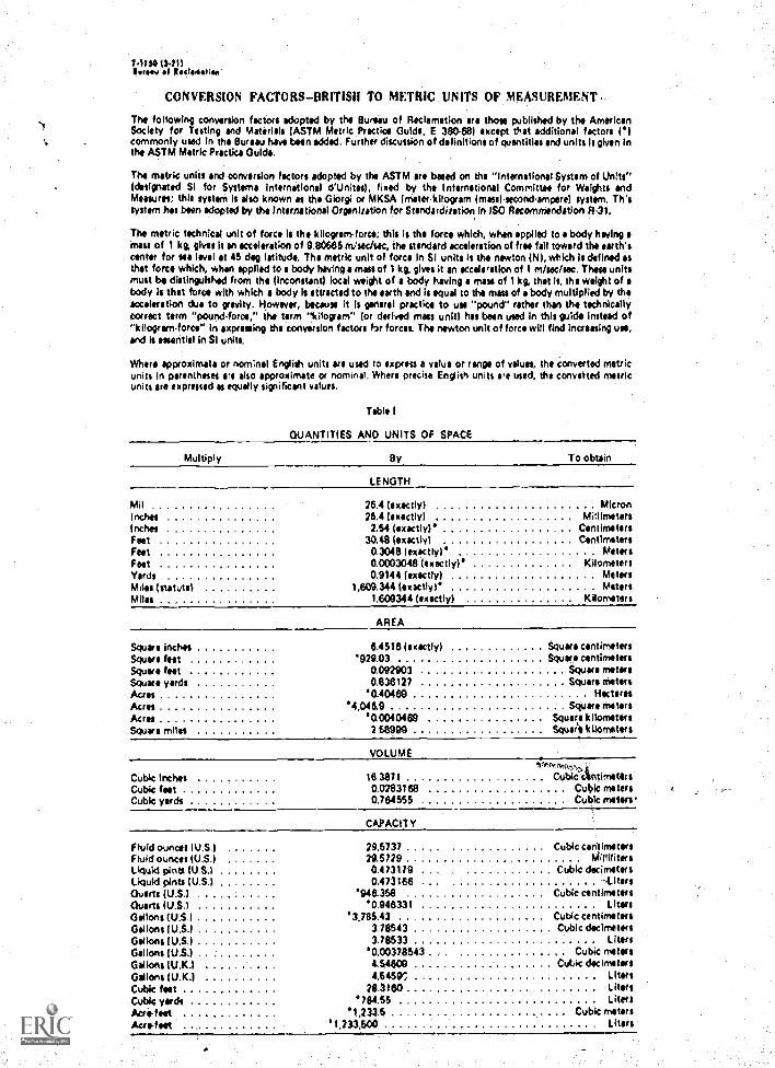
CONVERSION FACTORS-BRITISH TO METRIC UNITS OF MEASUREMENT
The following conversion factors adopted by the Bureau of Reclamation are those published by the AmericanSociety for Testing and Materials (ASTM Metric Practice Guide, E 38468) except that additional factors ('Icommonly used in the Bureau have been sodded. Further discussion of definitions of quantities and units Is given Inthe ASTM Metric Practice Guide.
The metric units and conversion factors adopted by the ASTM are based on the "International System of Units"(designated SI for Systeme International d'Unites), fixed by the International Committee for Weights andMeasures: this system is also known as the Giorgi or MKSA (meter.kilogram (masel.secondampere) tystem. ThistYllem has been adopted by the international OrgenlratIon for Standardization In ISO Recommendation R.3),
The metric technical unit of force is the kilogram-force; this is the force which, when applied to a body having amass of 1 kg, gives it an acceleration of 9.80665 m/sec/sec, the standard acceleration of free fall toward the earth'scenter for see level at 45 deg latitude, The metric unit of force in SI unite is the newton (N), which Is defined asthat force which, when applied to a body having a mass of 1 kg, gives it an acceleration of I m/sec/sec. These unitsmust ba distinguished from the (inconstant) local weight of a body having a mast of 1 kg, that is, the weight of abody is that force with which a body le attracted to the earth and Is equal to the mass of a body multiplied by theacceleration due to gravity. However, because it is general practice to use "pound" rather than the technicallycorrect term "pound-force," the term "kilogram" (or derived mats unit) has been used In this guide Instead of"kilogram-force" in expressing the conversion factors for forces. The newton unit of force will find increasing use,and is essential in SI units.
Where approximate or nominal English units are used to express a value or range of values, the converted metricunits in parentheses are also approximate or nominal. Where precise English units are used, the convected metricunits are expressed as equally significant values.
Table I
QUANTITIES AND UNITS OF SPACE
Multiply By
LENGTH
To obtain
Mil 25.4 (exactly) MicronInches 25.4 (exactly) MillimetersInches 2.54 (exactly)' CentimetersFeet 30.48 (exactly) CentimetersFeet 0.3048 lexectly) MetersFeet 0.0003048 (exactly)' KilometersVerde 0.9144 (exactly) MetersMilts (statute) 1,609.344 (exactly)' MetersMiles 1.609344 (exactly) Kilometers
AREA
Square inches 5.4516 (exactly) Square centimetersSquare feet '929.03 Square centimetersSquare feet 0.092903 Square metersScum* yards 0.838127 Square metersAcres '0.40469 HectaresAcres '4,046.9 Square metersAcres '0,0040469 Square kilometersSquare miles 158999 Squar'is kilometers
VOLUME
Cubic inches 16.3871 CubittlintimetertCubic test 0.0283168 Cubic metersCubic yards 0.764555 Cubic milers.
CAPACITY
Fluid ounces (U.S 1 29.5737 Cubic centimetersFluid ounces (US.) 29.5729 MillilitersLiquid pints (U S 1 0.413179 Cubk decirnotetsLiquid pints (U S) 0.4731613 -LitersOvens (U S 1 '945.358 Cubic centimetersQuarts (U S 1 '0.946331 LitersGallons (U.S.I '3,785.43 Cubic centimetersGallons (U.S.I 3.78543 Cubic decimetersGallons (U.S.) 3.78533 LitersGallons (US.) '0.00378543 Cubic metersGallons (U.K.) 4.54600 Cubic decimeters
Gallons (U.K.1 4.545V LitersCubic feet 28.3160 LitersCubic verde *784,55 LitersAcrefest '1,233.5 Cubk metersAcre -feet '1,233,500 Liters
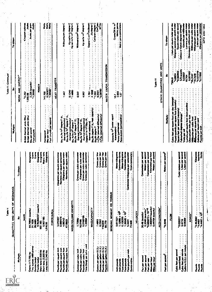
QW
uJ
LLQ
V Ord
I 111111111f' ill1 I
hilml
ddv
salt
dd-
6
15
8
I
Pill
5
III
0a
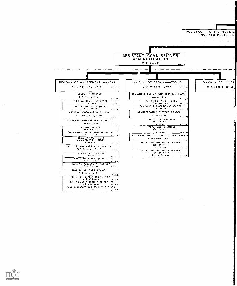
rillirlreff§111111IF
ASSISTANT TO THE COMMISPROGRAM POLICIES
ASSISTANT COMMISSIONERADMINISTRATION
W.P. KANE CODE
II-
DIVISION OF MANAGEMENT SUPPORT
W. Lange, Jr., Chief CODE BOO
ACCOUNTING BRANCH
E A Br Own, ChetCODE 500
FINANCIAL OPERATIONS SECTIONC L Winn 30.OEO[
SYSTEMS ACCOUNTING SECTIONR V Leonora CODE 302
PROGRAM COORDINATION BRANCHN L 5cNIcat,ng, Chief
000C 500
PERSONNEL MANAGEMENT BRANCHP v Oieert, Cnief
STAFFING SECTIONM K N.elson ODE SO
MANAGEMENT AND DEVELOPMENT SECTIONW C Miner CODE Co.
EQUAL OPPORTUNITY ANDLABOR RELATIONS SECTION
F W Retail
PROPERTY AND PURCHASING BRANCHM S Greenlee, Chief
CODE Sift
PURCHAS NG SECTIONVacancy
PROPERTYAND WAREHOUSE SECT Ncone
G G Hooper CODE 0
BUILDING MANAGEMENT SECTIONR L Wotf,ns CODE It)
GENERAL SERVICES BRANCHC R Biped°, n, Chief
CODE 900
FACILITATING SERVICES SECTIONA McAdams CODE 910
PRINTING AND DISTRIBUTION SECT IONR E MCGregor cone no
CORRESPONDENCE AND RECORD 5 SECT IONT B Bell CODE 950
DIVISION OF DATA PROCESSING
D.W. Webber, Chief CODE 970
OPERATIONS AND SUPPORT SERVICES BRANCHvacancy, Chief
CODE ItO
SYSTEMS SOFTWARE SECTIONF R C.I0dC000 CODE
EQUIPMENT AND OPERATIONS sELC R Ferguson COO! 2
ADMINISTRATIVE SYSTEMS BRANCHG 5 M.Iler, Chef
CEDE .,0
SYSTEMS A..D PROGRAMINGSECTION NO
Vas ono CODE
SYSTEMS AND PROGRAMINGSECTION NO 2
Vacancy CODE
ENGINEERING AND SCIENTIFIC SYSTEMS BRANCIL .1 Burton, Chef
CODE "30
SYSTEMS ANALYSIS AND DEVELOPMENTSECTION NO
D R Locke CODE .45
SYSTEMS ANALYSIS AND DEVELOPMENTSECTION ND 2
D L McGomara CODE ,t52
DIVISION OF SA ETR. J. Seorle, Chief
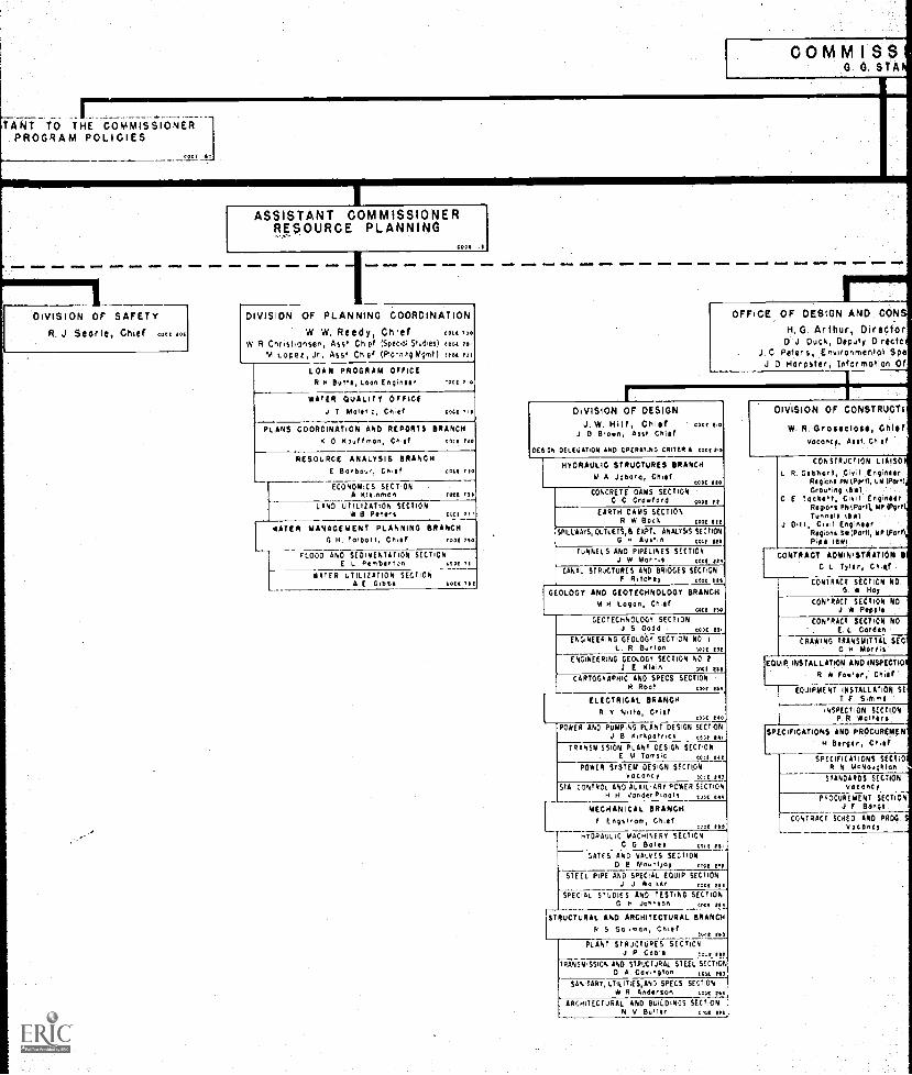
COMM I SS0. O. STA
TANT TO THE COMMISSIONERPROGRAM POLICIES
CODI
ASSISTANT COMMISSIONERRESOURCE PLANNING
COI/ I.I
DIVISION OF SAFETYR. J. Searle, Chief cunt jot
1DIVISION OF PLANNING COORDINATION
W. W. Reedy, Chief COCA POO
W R,CrIfithanterl, ASS /. Chef tSpeco; Sludes) cool mLOpeR, Jr, Asst Chief (Plonhni Mgmt) trot yo,
LOAN PROGRAM OFFICER Butte, Loon /noires, 0001 Tit
WATER QUALITY OFFICEJ T Maitr,c, Cnier LOCI 1O
PLANS COORDINATION AND RIPORIS BRANCHtt 0 K /man, CI IT cut rio
RESOURCE ANALYSIS BRANCHC Bar Dour, CnIef Cott /10
ECONOMICS SECTIONAltnman
LAND UTILIZATION SECTIONSY B PAW s
COCA /II
cool P.
LWATER MANAGEMENT PLANNING BRANCH
G H Tai Dot I, Ch./1 root rso
FLOOD AND SEDIMENTATION SECTIONE L Pemberton toot 1.s
RATER UTILIZATION SECTIONA E G.Dts coot 761
OFFICE OF DESIGN AND CONSH. G. Arthur, Director
J Duck, Deputy Directol
J. Peters, Ersironmenlol SpeJ D Harpster, Infor maTiorl Of
DIVISION OF DESIGNJ.W. Hitf, Chief
J 0 Bronn, Asst ChiefCOD0 1,0
DESIGN DELEGATION AND OPERATAG CRITERIA coot tns
HYDRAULIC STRUCTURES BRANCH1,1 A Jabara, CYIST
CONCRETE DAMS SECTIONC C Cranford 000I CAI
COO, 010
EARTH DAMS SECTIONW Batt COOL 1/C
SPILLWAYS, OutLEIS,B EYPTL ANALYSIS SECTIONH Austin tout et!
FUNNELS AND PIPELINES SECTIONW Morris COO( lit
CANAL STRUCTURES AND BRIDGES SECTIONF RIchey COOt /PI
GEOLOGY AND GEOTECHNOLOGY BRANCHM H Logan, Chief
COD1 P 0
LEOTECHNOLOGY SECTIONJ S Oodd COI ID.
ENGINEERING GEOLOGY SECTION NO I
R Burton COCO 11/
ENGINEERING GEOLOGY SECTION NO. 2I E Klein C.001 /11!
CARTOGRAPHIC AND SPECS SECTIONR Roof 01/01 134
ELECTRICAL BRANCHY
CDR 140
POWER AND PUMPING PLANT DESIGN SECTIONJ B X,rkpotr,clk tss,
TRANSMISSION PLANT COSIGN SECTIONE M Toms.c CM 140
LONER SYSTEM DESIGN SECTIONH00000 y COCA /43
STA CONTROL AND AuxiLiART POWER SECTIONH 11 VOndtrP.0011 tub/ tta
MECHANICAL BRANCHF Engstrom, Ch AF
ccor r1
HYDRAULIC MACHINERY SECTIONC G Botts 0011 t3.
GATES ANT VALUES SECTIONB reovnt,oy ovc top
STEEL PIPE AND SPECIAL EQUIP SECTIONJ *01510 Cott 111
SPECIAL STUDIOS AND TESTING SECTIONG H jonnson toot tot
STRUCTURAL AND ARCHITECTURAL BRANCHN 5 541,neN, that
Toot PIO
PLANT STRUCTURES SECTIONP Coals ea.r elf
RANS4,SSION AND STRUCTURAL STEEL SECTIONO A Co,,noton COIL 4.,
SAStIARY, uTILITTES,AND SPECS SECTIONW. R Anderson coot 1444
ARCHITECTURAL AND BUILDINGS SECTIONN V Buller cvv
DIVISION OF CONSTRUOTt
W. R. Groseclose, CHOVacancy, Asst. 011ie
L RCONSTRUCTION LIAISOI
GoDhgrt, Civ il (flimsy.Region* PN (Poo), UN WIWI)Grouting INC
C ( tooluert, Cluit EngineitRegions PN(Pa,II, MP(PRrtlTunnel/ (ROI
J. DIII Owl EnginairReg ont S*(PartI, NP {Part)Pie* IOC
CONTRACT ADMINISTRATION IIC I roil., GIRT
CONTRACT SECTION NOG. N Hay
CONTRACT SECTION NOJ W Popp!'
CONTRACT SECTION NO.
E CordonCRANING TRANSMITTAL SEC
C H. sAorrI
EQUIP,e iP. INSTALLATION AND INSPECTIO
R A. Fonler, Chita
EQUIPMENT INSTALLATION SET F. Stool
INSPECTION SECTIONP R. Wolters
SPECIFICATIONS AND PROCUREPEEN
H Bergin, CA.EF
SPECIFICATIONS SECTIOR N McNoughtan
STANDARDS SECTIONRota my
PROCUREMENT SECTIONF BOON,
CONTRACT SCNED AND PROSvAeoNcy
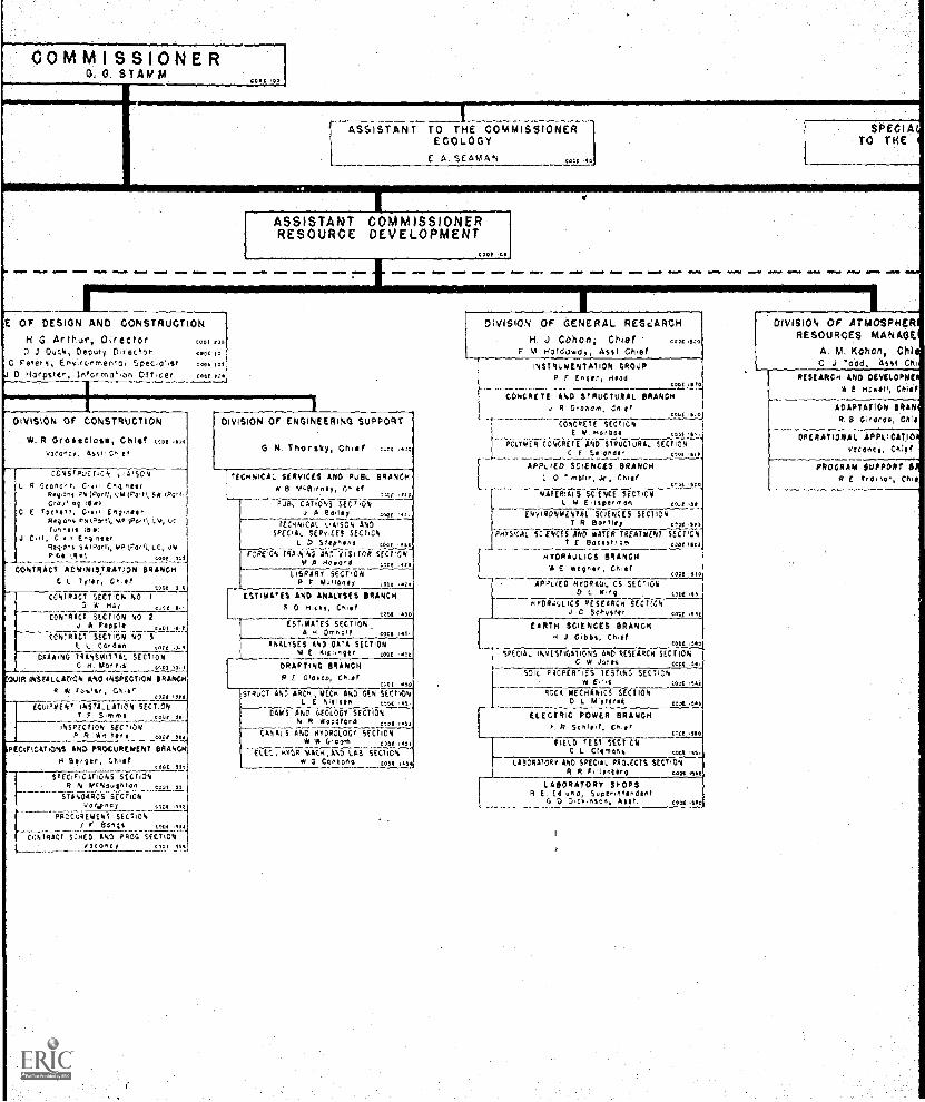
COMM I SSIONER0, 0, STAMM
CODS Co
LASSISTANT TO THE COMMISSIONER
ECOLOGY
E A. SE/5.'0M,,
SPECIATO THE
et .10
ASSISTANT COMMISSIONERRESOURCE DEVELOPMENT
E or DESIGN AND CONSTRUCTIONG Arthur, Director
0 J Duck, Deputy 04ectorC peter,, Ent fcnmenitl Specost
Harwer, Infe,moi,on Off .CRY coo. too
:C01 010
in(cool 101
DIVISION Of CONSTRUCTION
W. R OYOSACIOAS, C1110 cope .DolLoccocy, Ass, C^
coNiTPL.0 NON Lt A1SON
L R Gooreoot, C4.1 Coq ',offkfqDol iN (Fork, l AD ;Parr), 54
C C %testi, Co o En.gnteReq C'S ckloor 00 Ve. ;ow), LN,%,,,t is IS
J 0,11, Cl' E n4.ne er74,1.0,7 5A ',PP' rr, VP k000), Lc, uNPOl ISA,, 0001 7,LS,
CONTRACT ADST,NISTRATIDN BRANCHC L 7yl,r, CNA,'
e,ee I eCONIPACT SECTION NO
5 A HA, colt I,CONTRACT SECTION NO 2
J W PAW.,r I -I
CONTRACT SECTION NO 3
E L Gordon Corr FtcFAA,No TRANSMITTAL sEtToN
Morns corl .1
21/1R INSTALLATION ANO INSPECTION BRANCH
44 c0101, C.. ifCOOS ,110
fOwPWENT INSTALLATION SECTIONT F 00.00 It
INSPECtf(PY SECTIONP R 1.1W141r$ toot
PECIFICATIONS AND PROCUREMENT BRANCH
ca,,erCODE 150
soccie,cAnoNs SECTIONFlR Mckaoc+Tal ,,,,,,
STANSIROS SECTIONvn to nc y (..e .Ilt
PROCkiDDIETiT SECTION1 F Bangs cOe4 114
CONIRAC I SCRED ILINO FROG SECTIONstoney 0001 Ott.
DIVISION Of ENGINEERING SUPPORT
G. N. Thor sky, Chief e,ec ,000
TECHNICAL SERVICES AND PUBL. BRANCHB mcB.rne,
tr .4:oF.8. CATIONS SEC 7104
,/ A 81171y D:4( 4
rEcoitcp, t.A'SON ANDSPECIAL SEin CES SECTION
D Selp"ens cn
rcqcs rqa,N'N; AND '151 rna SECTIONNT A 80wod :lee .54
LIBRARY SECTIONP F No.oioney coa
ESTIMATES AND ANALYSES BRANCH0 *I Os, CRel
toot 410
CPA
ESTIMATES SECTION4 H 0,1thZ11 1001
ANALYSES AND DATA SECTIONE ,qtr cOCE
DRAFTING BRANCHE C,disco, er
41,
<011
sTqucT ENO ERL4, ToEco, AND GEN SECTIONL E NlereAR coot
CAMS AND GEOLOGY SECTIONR A000loed co OE X414
CANALS AND HYDROLOGY SECTIONW Grove, 004 III
W450 MAGA ,AND LAB SECTIONW G CRFWG 1004 J.0
DIVISION OF GENERAL RESCARCHH. J. Cohan, Chief cost sao
F M tfoIdovely, Asst ChiefINSTRUMENTATION GROUP
F Unger, H104L_.
CONCRETE AND STRUCTURALJ R ar011m,
Cool 400
BRANCH
CM ICONCRETE SECTION
IN Harboi tootr. POLYMER CONCRETE AND SIRLICluRAL SECTION
C E Selonaer 0,114 Ort.
APPLIED SCINCES BRANCH0 7"b1,, Jr, Chief
cDDE 140
MATERIALS SCIENCE SECTIONL M C 110p100 An c,Le 031,
ENVIRONMENTAL SEANCES SECTIONT R SOD tlfp
PHYSICAL SCIENCES ENO *VIP 11E4141547 SECTION7 E BatAeleo, coot 'It;
HYDRAULICS BRANCH* E Wiwi', 05141
LOCI
AMA() HraRtQLiCs SECTIOND l Fng 001 .61
HfOR4:,LIC5 RESFARC.4 sEcrviC, Sch.stie 0.4 VIII
EARTH SCIENCES BRANCHR J. Cobb,, CAyr
CODE 140
SPECIAL INVESTIGATIONS ANC. RESEARCH SECTIONC W Arts Coot III
SOIL PROPERTIES TESTING SECTIONH. Eris Loot ,540
40(5 MECHANICS SECTION0 L Mietorek cox
ELECTRIC POWER BRANCHF Cor
Coot 51-0
FIELD TEST SECTIONC L CIAoco% coot ,15.
LABORATORY AND SPECIAL oa04ccis 5101344R R F r4oberg coot et se
LABORATORY SHOPSR E Ed umd, SuperothprAent
G 0 001,0son, Ault 1404
DIVISION OF ATMOSPHERRESOURCES MANAGE
A. M. Kohort, ChlC J Todd, ASST Ch
RESEARCH AND DEVELOPMEIN E H0D111, Chief
ADAPTATION BRANR. B GlYRYdo, Chi1
OPERATIONAL APPLICATIO
V. CR`Al
PROGRAM SUPPORTR E rya1 Sor, chi*
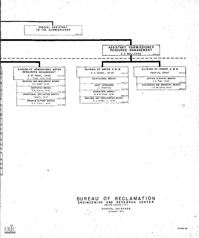
SPECIAL ASSISTANTTO THE COMMISSIONER
rapt O
IASSISTANT COMMISSIONERRESOURCE MANAGEMENT
E. F. SULLIVAN
LDIVISION OF ATMOSPHERIC WATER
RESOURCES MANAGEMENTA. M. Kahan, ChiefC J Todd, ftsst CP,ef
LODI .1}0
RESEARCH AND DEVELOPMENT BRANCH'A ( HoNen, Crer r. a
ADAPTATION BRANCHR B 0,earop, pale,
(DEE .E10
OPERATIONAL APPLICATION BRANCHVacancy, cn er
a',ar up
PROGRAM SUPPORT BRANCHR E Tra,rar, 0,0
tOGE 140
IDIVISION OF WATER 0 a M
K. K. Kober, Chief ODD, AGO
MAINTENANCE BRANCH
EIDE
CHIEF APPRAISERL RobArryon Eta IO
OPERATIONS BRANCHB A Prcrard, CY Nr
DOH 4.10
DRAINAGE AND GROUNDWATER BRANCHN J woger, Jr, Cnef
capit SAG,
DIVISION OF POWER 0 8 MVoconcy, Chief coot 100
SYSTEM PLANNING BRANCHC L Rafe, CRAY
cop, 110
ENGINEERING AND OPERATION BRANCHJ E S1aderoA, Co. ,
COOL NO
BUREAU OF RECLAMATIONENGINEERING AND RESEARCH CENTER
I BELOW DASHED LINE)
DENVER, COLORADOOCTOBER ,ITS
GPO 850. <98