Embed Size (px)
Citation preview
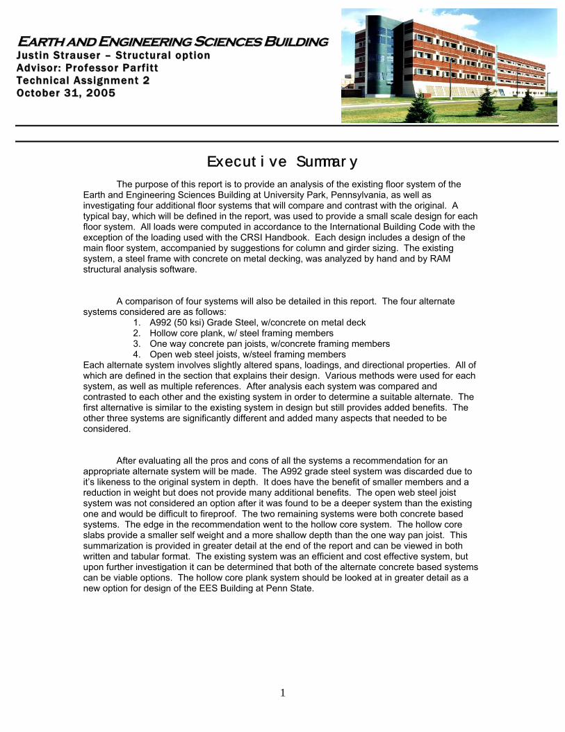
EEaarrtthh aanndd EEnnggiinneeeerriinngg SScciieenncceess BBuuiillddiinngg JJuuss tt ii nn SStt rraauuss ee rr –– SStt rruucc ttuu rraa ll oo pp tt iioo nn AA ddvv ii ssoo rr :: PPrroo ffee ssss oo rr PP aarr ff ii tt tt TT ee cchhnn ii ccaa ll AA ssss iigg nnmmee nntt 22 OO cc ttoo bbee rr 3311 ,, 22000055
1
Executive Summary
The purpose of this report is to provide an analysis of the existing floor system of the Earth and Engineering Sciences Building at University Park, Pennsylvania, as well as investigating four additional floor systems that will compare and contrast with the original. A typical bay, which will be defined in the report, was used to provide a small scale design for each floor system. All loads were computed in accordance to the International Building Code with the exception of the loading used with the CRSI Handbook. Each design includes a design of the main floor system, accompanied by suggestions for column and girder sizing. The existing system, a steel frame with concrete on metal decking, was analyzed by hand and by RAM structural analysis software.
A comparison of four systems will also be detailed in this report. The four alternate
systems considered are as follows: 1. A992 (50 ksi) Grade Steel, w/concrete on metal deck 2. Hollow core plank, w/ steel framing members 3. One way concrete pan joists, w/concrete framing members 4. Open web steel joists, w/steel framing members
Each alternate system involves slightly altered spans, loadings, and directional properties. All of which are defined in the section that explains their design. Various methods were used for each system, as well as multiple references. After analysis each system was compared and contrasted to each other and the existing system in order to determine a suitable alternate. The first alternative is similar to the existing system in design but still provides added benefits. The other three systems are significantly different and added many aspects that needed to be considered.
After evaluating all the pros and cons of all the systems a recommendation for an
appropriate alternate system will be made. The A992 grade steel system was discarded due to it’s likeness to the original system in depth. It does have the benefit of smaller members and a reduction in weight but does not provide many additional benefits. The open web steel joist system was not considered an option after it was found to be a deeper system than the existing one and would be difficult to fireproof. The two remaining systems were both concrete based systems. The edge in the recommendation went to the hollow core system. The hollow core slabs provide a smaller self weight and a more shallow depth than the one way pan joist. This summarization is provided in greater detail at the end of the report and can be viewed in both written and tabular format. The existing system was an efficient and cost effective system, but upon further investigation it can be determined that both of the alternate concrete based systems can be viable options. The hollow core plank system should be looked at in greater detail as a new option for design of the EES Building at Penn State.
EEaarrtthh aanndd EEnnggiinneeeerriinngg SScciieenncceess BBuuiillddiinngg JJuuss tt ii nn SStt rraauuss ee rr –– SStt rruucc ttuu rraa ll oo pp tt iioo nn AA ddvv ii ssoo rr :: PPrroo ffee ssss oo rr PP aarr ff ii tt tt TT ee cchhnn ii ccaa ll AA ssss iigg nnmmee nntt 22 OO cc ttoo bbee rr 3311 ,, 22000055
2
Existing Structural Floor System Composite 36 ksi Steel Beams w/Concrete on Metal Deck The existing floor system is composed of composite action steel beams that work in conjunction with the floor slab system. The steel used in the system is primarily 36 ksi grade steel. There are a few exceptions where 50 ksi grade steel was used, but predominantly the 36 ksi steel is found. The slab system has three deck types, however the most common deck a 3”, 20 GA galvanized composite metal deck with 3 ¼ “ light weight concrete topping reinforced with 6 x 6, W2.1 x W2.1 welded wire fabric will be used in this study. This deck, commonly referred to as Slab 1, is used in most floor spaces with the exception of some high live load areas such as stairwells. The beams frame into steel girders which help transfer the load to the steel columns. The columns then transfer the load to the concrete piers and footings that they rest on.
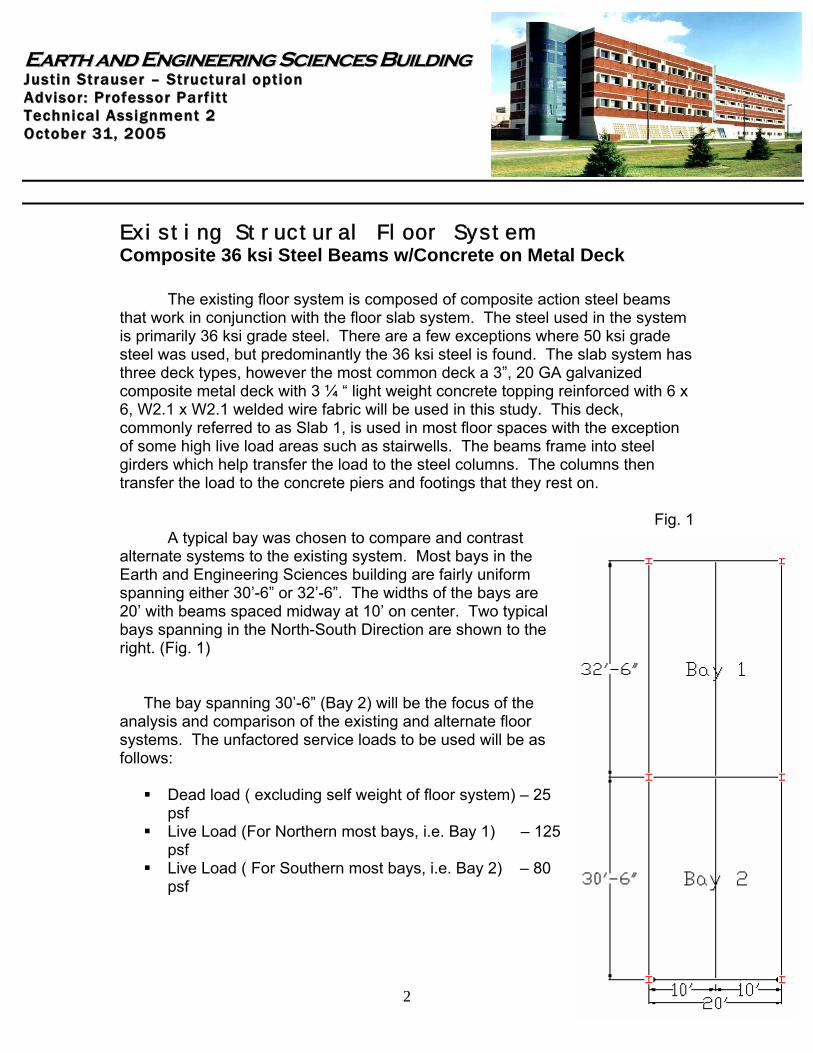
Fig. 1 A typical bay was chosen to compare and contrast alternate systems to the existing system. Most bays in the Earth and Engineering Sciences building are fairly uniform spanning either 30’-6” or 32’-6”. The widths of the bays are 20’ with beams spaced midway at 10’ on center. Two typical bays spanning in the North-South Direction are shown to the right. (Fig. 1)
The bay spanning 30’-6” (Bay 2) will be the focus of the analysis and comparison of the existing and alternate floor systems. The unfactored service loads to be used will be as follows:
Dead load ( excluding self weight of floor system) – 25 psf
Live Load (For Northern most bays, i.e. Bay 1) – 125 psf
Live Load ( For Southern most bays, i.e. Bay 2) – 80 psf
EEaarrtthh aanndd EEnnggiinneeeerriinngg SScciieenncceess BBuuiillddiinngg JJuuss tt ii nn SStt rraauuss ee rr –– SStt rruucc ttuu rraa ll oo pp tt iioo nn AA ddvv ii ssoo rr :: PPrroo ffee ssss oo rr PP aarr ff ii tt tt TT ee cchhnn ii ccaa ll AA ssss iigg nnmmee nntt 22 OO cc ttoo bbee rr 3311 ,, 22000055
3
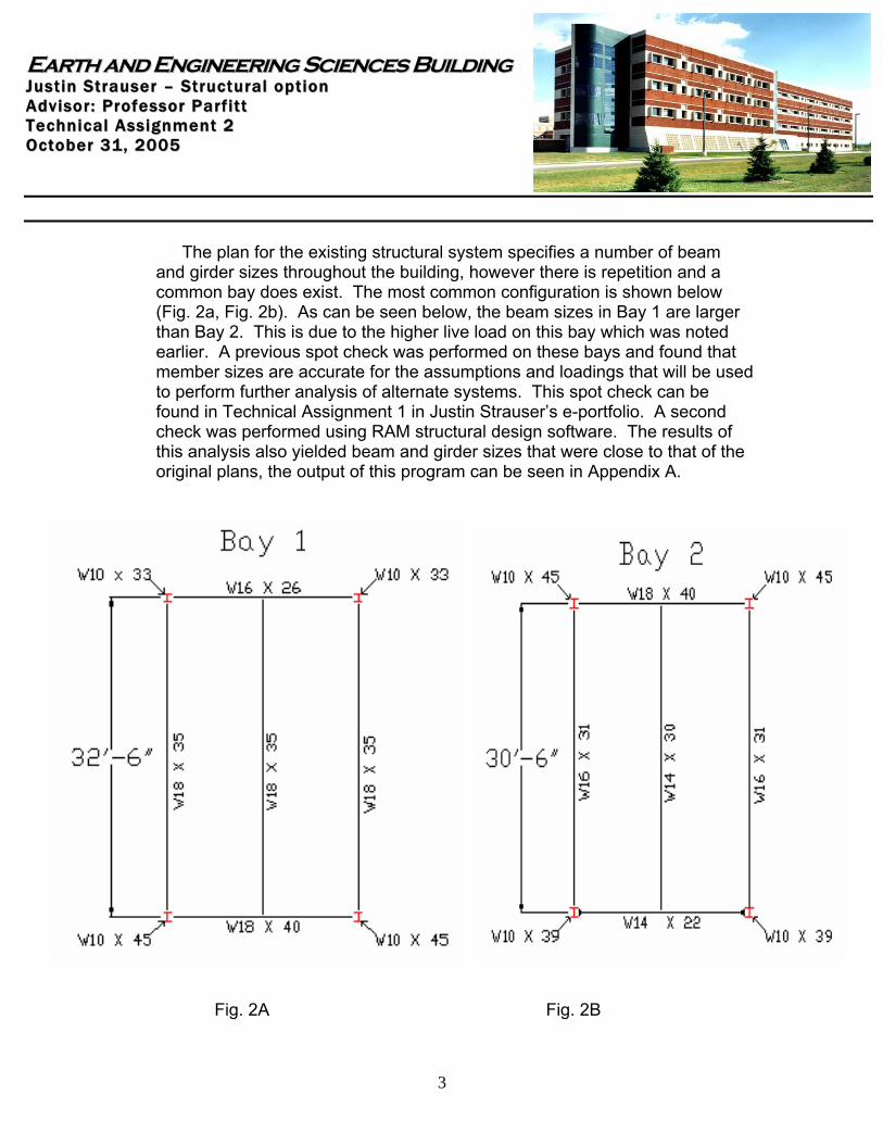
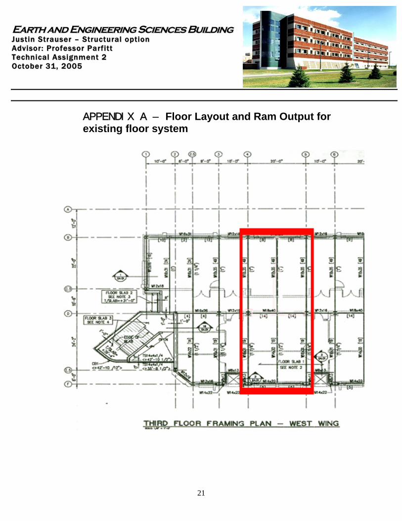
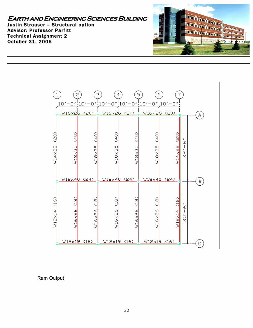
The plan for the existing structural system specifies a number of beam and girder sizes throughout the building, however there is repetition and a common bay does exist. The most common configuration is shown below (Fig. 2a, Fig. 2b). As can be seen below, the beam sizes in Bay 1 are larger than Bay 2. This is due to the higher live load on this bay which was noted earlier. A previous spot check was performed on these bays and found that member sizes are accurate for the assumptions and loadings that will be used to perform further analysis of alternate systems. This spot check can be found in Technical Assignment 1 in Justin Strauser’s e-portfolio. A second check was performed using RAM structural design software. The results of this analysis also yielded beam and girder sizes that were close to that of the original plans, the output of this program can be seen in Appendix A.
Fig. 2A Fig. 2B
EEaarrtthh aanndd EEnnggiinneeeerriinngg SScciieenncceess BBuuiillddiinngg JJuuss tt ii nn SStt rraauuss ee rr –– SStt rruucc ttuu rraa ll oo pp tt iioo nn AA ddvv ii ssoo rr :: PPrroo ffee ssss oo rr PP aarr ff ii tt tt TT ee cchhnn ii ccaa ll AA ssss iigg nnmmee nntt 22 OO cc ttoo bbee rr 3311 ,, 22000055
4
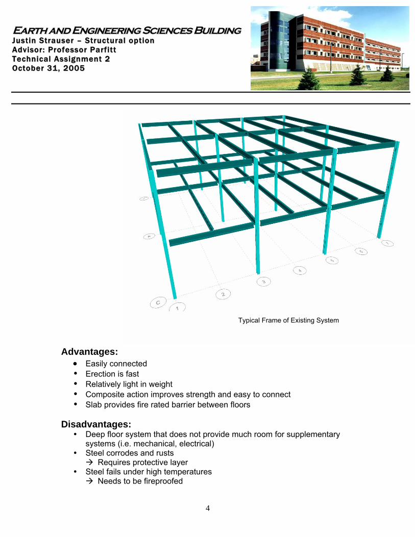
Typical Frame of Existing System Advantages:
• Easily connected Erection is fast Relatively light in weight Composite action improves strength and easy to connect Slab provides fire rated barrier between floors
Disadvantages:
Deep floor system that does not provide much room for supplementary systems (i.e. mechanical, electrical)
Steel corrodes and rusts Requires protective layer
Steel fails under high temperatures Needs to be fireproofed
EEaarrtthh aanndd EEnnggiinneeeerriinngg SScciieenncceess BBuuiillddiinngg JJuuss tt ii nn SStt rraauuss ee rr –– SStt rruucc ttuu rraa ll oo pp tt iioo nn AA ddvv ii ssoo rr :: PPrroo ffee ssss oo rr PP aarr ff ii tt tt TT ee cchhnn ii ccaa ll AA ssss iigg nnmmee nntt 22 OO cc ttoo bbee rr 3311 ,, 22000055
5
Alternate Structural Floor System 1 Composite and Non-Composite 50 ksi Steel Beams w/Concrete on Metal Deck The first alternative system was to change the steel from 36 ksi steel to 50 ksi steel. This change could be more efficient in that smaller beams could be used reducing the amount of steel used throughout the building. Smaller beams could also reduce the amount of space wasted between floors. This system’s performance will be evaluated as both composite and non-composite. This system will also be designed using repetitive members with no changes in beams. A 2”, 18 gauge, unshored LOK floor, topped with 3” light weight concrete providing a 2 hour fire rating will be used in the design. Service Loads
Dead load ( excluding self weight of floor system) – 25 psf Live Load (For Northern most bays, i.e. Bay 1) – 125 psf Live Load ( For Southern most bays, i.e. Bay 2) – 80 psf
Material Properties f’c = 3 ksi fy = 50 ksi Composite Design wu = 1.2(25 psf) + 1.6(80 psf) = 158 psf Mu = (.158 ksf)(10 ft)(30.5 ft)2/8 = 183.7 ft-k Assume a = 1.0” Y2 = 5” – (1.0”/2) = 4.5 “ Using Table 5-14 from AISC Manual for Steel Construction with Y2 = 4.5”
Try W14 x 22 with Y1 @ location 6 beff = lesser of spacing or L/4, 120” and 91.5” respectively beff = 91.5”
EEaarrtthh aanndd EEnnggiinneeeerriinngg SScciieenncceess BBuuiillddiinngg JJuuss tt ii nn SStt rraauuss ee rr –– SStt rruucc ttuu rraa ll oo pp tt iioo nn AA ddvv ii ssoo rr :: PPrroo ffee ssss oo rr PP aarr ff ii tt tt TT ee cchhnn ii ccaa ll AA ssss iigg nnmmee nntt 22 OO cc ttoo bbee rr 3311 ,, 22000055
6
Check assumption: a = 119 k/.85(3 ksi)(91.5”) = .51” Y2 = 5” – (.51”/2) = 4.74 “ => O.K. Check for efficiency:
*Based on shear capacity of studs = 21 k per stud The most efficient beam size for this design would be the W14 x 22. It may not be the lightest selection, but the 12 shear studs for the W14 x 22, as opposed to the 20 shear studs for the W12 x 19, would take less time and money to connect. The W14 x 22 would also provide a little more bending strength than the W12 x 19. Check deflection criteria: ∆LL = 5(.8 klf)(30.5 ft)4(1728)/384(29,000 ksi)(423 in4) = 1.27 “ > L/360 = 1.02 “ < L/180 = 2.03” Will work! ∆DL = 5(.43 klf)(30.5 ft)4(1728)/384(29,000 ksi)(199 in4) = 1.45 “ > L/360 = 1.02 “ < L/180 = 2.03” Will work! Note: The inertia values for deflection were taken form Table 5-15 in the AISC Manual.
Beam Size ΦMp (ft-k) ΦMn (ft-k) ∑ Qn (k) *# of StudsW14x22 125 191 119 12.0W14x26 151 208 96.1 10.0W12x30 162 219 110 12.0W12x26 140 189 95.6 10.0W12x22 110 187 153 16.0W12x19 92.6 186 208 20.0W10x26 117 197 190 18.0
820770960
Total Weight (lbs)7808801020880
EEaarrtthh aanndd EEnnggiinneeeerriinngg SScciieenncceess BBuuiillddiinngg JJuuss tt ii nn SStt rraauuss ee rr –– SStt rruucc ttuu rraa ll oo pp tt iioo nn AA ddvv ii ssoo rr :: PPrroo ffee ssss oo rr PP aarr ff ii tt tt TT ee cchhnn ii ccaa ll AA ssss iigg nnmmee nntt 22 OO cc ttoo bbee rr 3311 ,, 22000055
7
Non-Composite Design
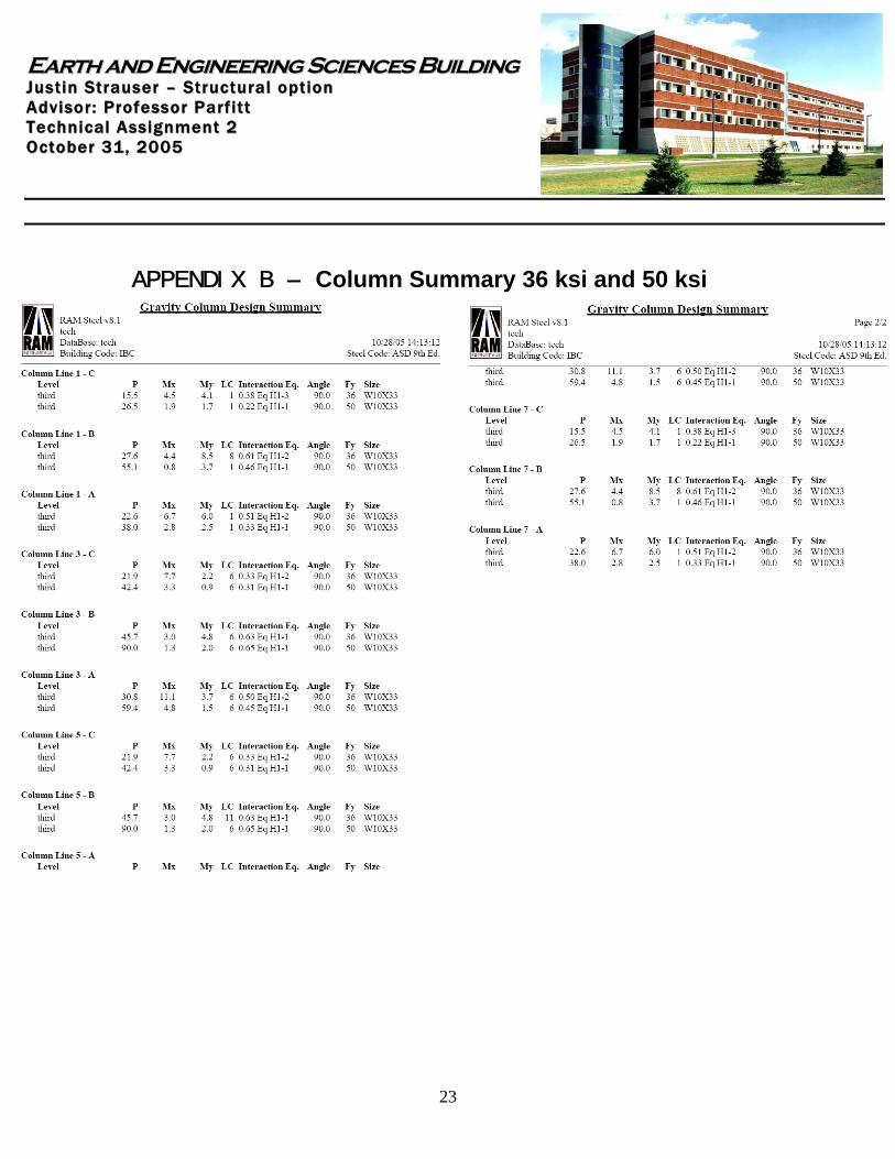
The beam no longer has composite action from slab and must take into account an added dead load from the slab when using the AISC beam design tables. Mu = 214 ft-k Assume unbraced length Lb = 30.5 ft From Beam Selection Table pg. 5-97 of the AISC Manual Use a W12 x 65 The use of a non-composite system would not be a good choice here. To obtain the same amount of strength as the composite system a much heavier beam would need to be used. When comparing the amount of steel alone of the W14 x 22 with 12 shear studs to that of the W12 x 65, it can be seen the disadvantage of this system. The W12 x 65 would be almost twice as heavy as its composite counterpart. This large amount of steel would increase the price of erection and fabrication costs. Therefore only the Composite 50 ksi system will be considered as an alternative to the existing system. A secondary analysis was done in RAM to calculate further member sizes. A typical layout can be seen below. Column sizes can be found in the summary located in Appendix B. Column sizes are W10 x 33, which did not change from the RAM selection for the existing system. Girder Consideration
The supporting girders for this alternate system will be taken from the RAM output file which can be found on the next page. The composite design provides smaller members than the existing system while the noncomposite suggests larger members,
EEaarrtthh aanndd EEnnggiinneeeerriinngg SScciieenncceess BBuuiillddiinngg JJuuss tt ii nn SStt rraauuss ee rr –– SStt rruucc ttuu rraa ll oo pp tt iioo nn AA ddvv ii ssoo rr :: PPrroo ffee ssss oo rr PP aarr ff ii tt tt TT ee cchhnn ii ccaa ll AA ssss iigg nnmmee nntt 22 OO cc ttoo bbee rr 3311 ,, 22000055
8
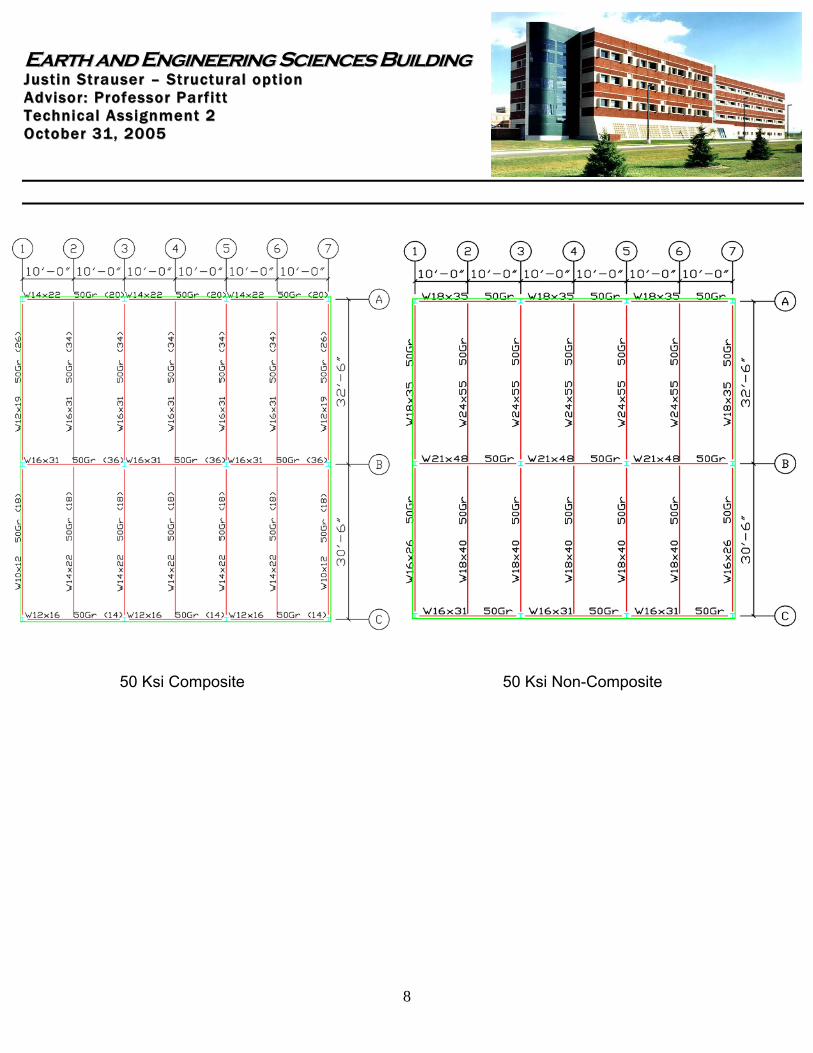
50 Ksi Composite 50 Ksi Non-Composite
EEaarrtthh aanndd EEnnggiinneeeerriinngg SScciieenncceess BBuuiillddiinngg JJuuss tt ii nn SStt rraauuss ee rr –– SStt rruucc ttuu rraa ll oo pp tt iioo nn AA ddvv ii ssoo rr :: PPrroo ffee ssss oo rr PP aarr ff ii tt tt TT ee cchhnn ii ccaa ll AA ssss iigg nnmmee nntt 22 OO cc ttoo bbee rr 3311 ,, 22000055
9
Advantages:
Easily connected Erection is fast Relatively light in weight, will be lighter than existing system (smaller
beams/columns) Composite action improves strength and easy to connect Slab provides fire rated barrier between floors
Disadvantages:
Deep floor system that does not provide much room for supplementary systems (i.e. mechanical, electrical), however will be more shallow than existing system
Steel corrodes and rusts Requires protective layer
Steel fails under high temperatures Needs to be fireproofed
EEaarrtthh aanndd EEnnggiinneeeerriinngg SScciieenncceess BBuuiillddiinngg JJuuss tt ii nn SStt rraauuss ee rr –– SStt rruucc ttuu rraa ll oo pp tt iioo nn AA ddvv ii ssoo rr :: PPrroo ffee ssss oo rr PP aarr ff ii tt tt TT ee cchhnn ii ccaa ll AA ssss iigg nnmmee nntt 22 OO cc ttoo bbee rr 3311 ,, 22000055
10
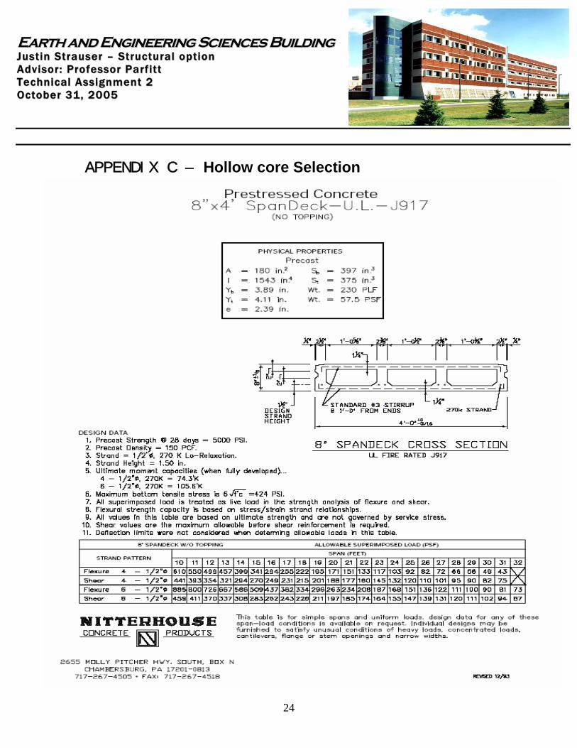
Alternate Structural Floor System 2 Prestressed Hollow Core Plank The second alternative system is a prestressed hollow core plank floor system. Hollow core planks are concrete planks fabricated off site and brought onto the job when needed. The prefabrication alone has its own disadvantages and advantages. Scheduling the delivery sequence is a major factor in the cost and efficiency of hollow core construction. However, when the planks are brought on site they are placed on girders or load bearing walls by a crane. The planks in this design will rest on steel girders that will frame into the columns. In order to keep the same bay configuration the planks have been selected to span the short direction. The same loading patterns used previously will be used in the design of this system. Design wu = 1.2(25 psf) + 1.6(80 psf) = 158 psf From PCI and Nitterhouse Tables using a span of 20’ (Table can be found in Appendix B) Use 8” x 4’ Spandeck – U.L. – J917 without topping Self weight 57.5psf 4 – ½ “Φ, 270 K, Low-Lax Strands f’c = 5000 psi
EEaarrtthh aanndd EEnnggiinneeeerriinngg SScciieenncceess BBuuiillddiinngg JJuuss tt ii nn SStt rraauuss ee rr –– SStt rruucc ttuu rraa ll oo pp tt iioo nn AA ddvv ii ssoo rr :: PPrroo ffee ssss oo rr PP aarr ff ii tt tt TT ee cchhnn ii ccaa ll AA ssss iigg nnmmee nntt 22 OO cc ttoo bbee rr 3311 ,, 22000055
11
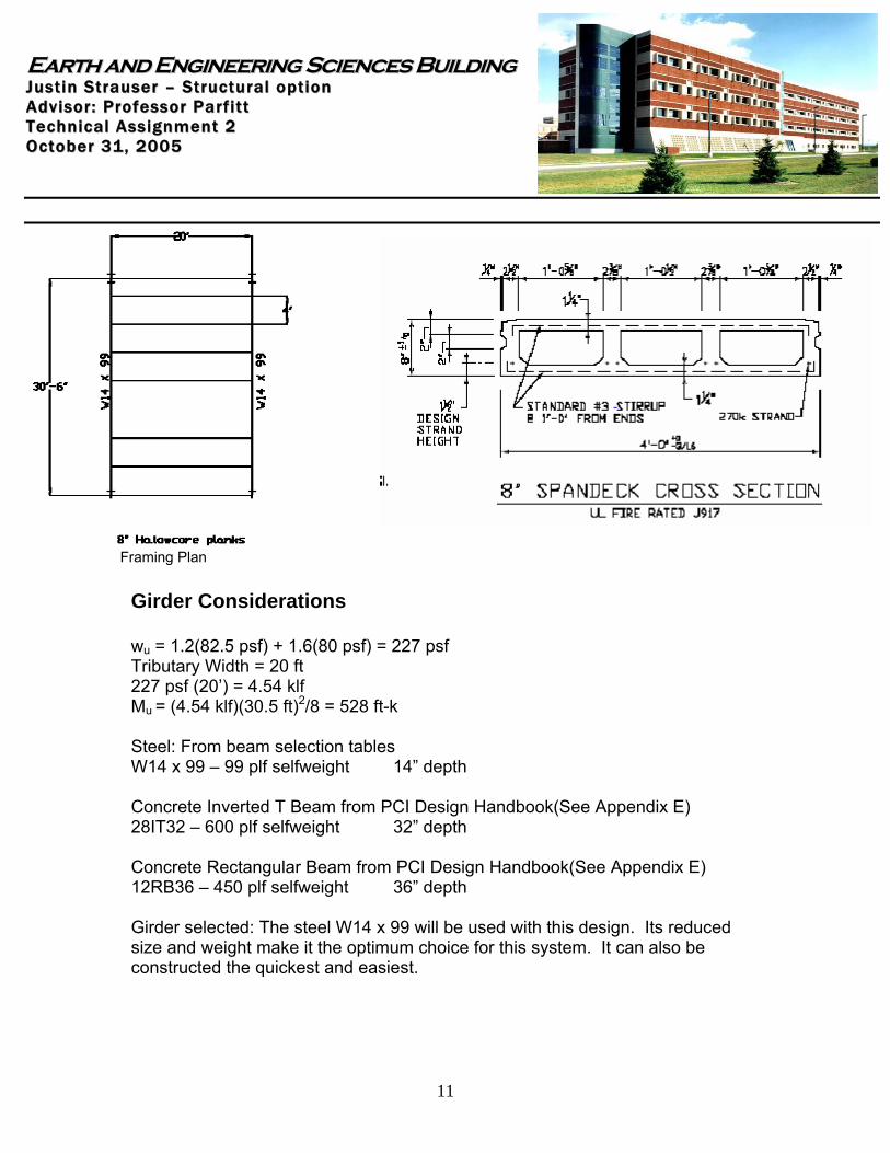
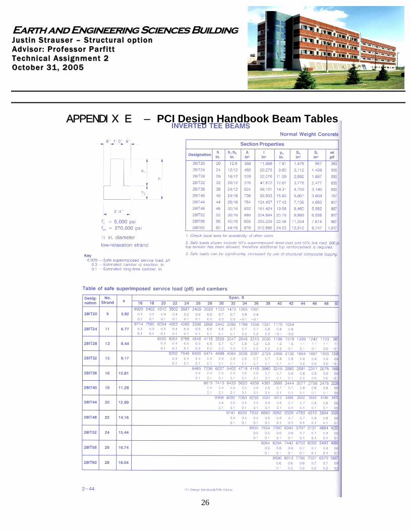
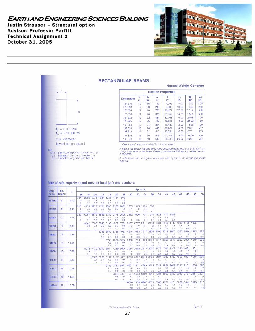
Framing Plan Girder Considerations wu = 1.2(82.5 psf) + 1.6(80 psf) = 227 psf Tributary Width = 20 ft 227 psf (20’) = 4.54 klf Mu = (4.54 klf)(30.5 ft)2/8 = 528 ft-k Steel: From beam selection tables W14 x 99 – 99 plf selfweight 14” depth Concrete Inverted T Beam from PCI Design Handbook(See Appendix E) 28IT32 – 600 plf selfweight 32” depth Concrete Rectangular Beam from PCI Design Handbook(See Appendix E) 12RB36 – 450 plf selfweight 36” depth Girder selected: The steel W14 x 99 will be used with this design. Its reduced size and weight make it the optimum choice for this system. It can also be constructed the quickest and easiest.
EEaarrtthh aanndd EEnnggiinneeeerriinngg SScciieenncceess BBuuiillddiinngg JJuuss tt ii nn SStt rraauuss ee rr –– SStt rruucc ttuu rraa ll oo pp tt iioo nn AA ddvv ii ssoo rr :: PPrroo ffee ssss oo rr PP aarr ff ii tt tt TT ee cchhnn ii ccaa ll AA ssss iigg nnmmee nntt 22 OO cc ttoo bbee rr 3311 ,, 22000055
12
Other Considerations The self-weight of the planks will increase the dead load seen be the columns by about 10 psf. This change will slightly increase the size of the columns needed to support the frame. Advantages:
Easily erected Fabricated Off Site reducing lag time Thin Slab Lighter than most concrete systems No forming to be done Easier to construct supplementary systems (i.e. electrical) Prefabrication assures consistency in properties (i.e. strength, quality,
durability)
Disadvantages:
Scheduling issues most be worked out due to prefabrication Fireproofing needed Needs slightly larger beam sizes or bearing walls to support Not as cost effective
EEaarrtthh aanndd EEnnggiinneeeerriinngg SScciieenncceess BBuuiillddiinngg JJuuss tt ii nn SStt rraauuss ee rr –– SStt rruucc ttuu rraa ll oo pp tt iioo nn AA ddvv ii ssoo rr :: PPrroo ffee ssss oo rr PP aarr ff ii tt tt TT ee cchhnn ii ccaa ll AA ssss iigg nnmmee nntt 22 OO cc ttoo bbee rr 3311 ,, 22000055
13
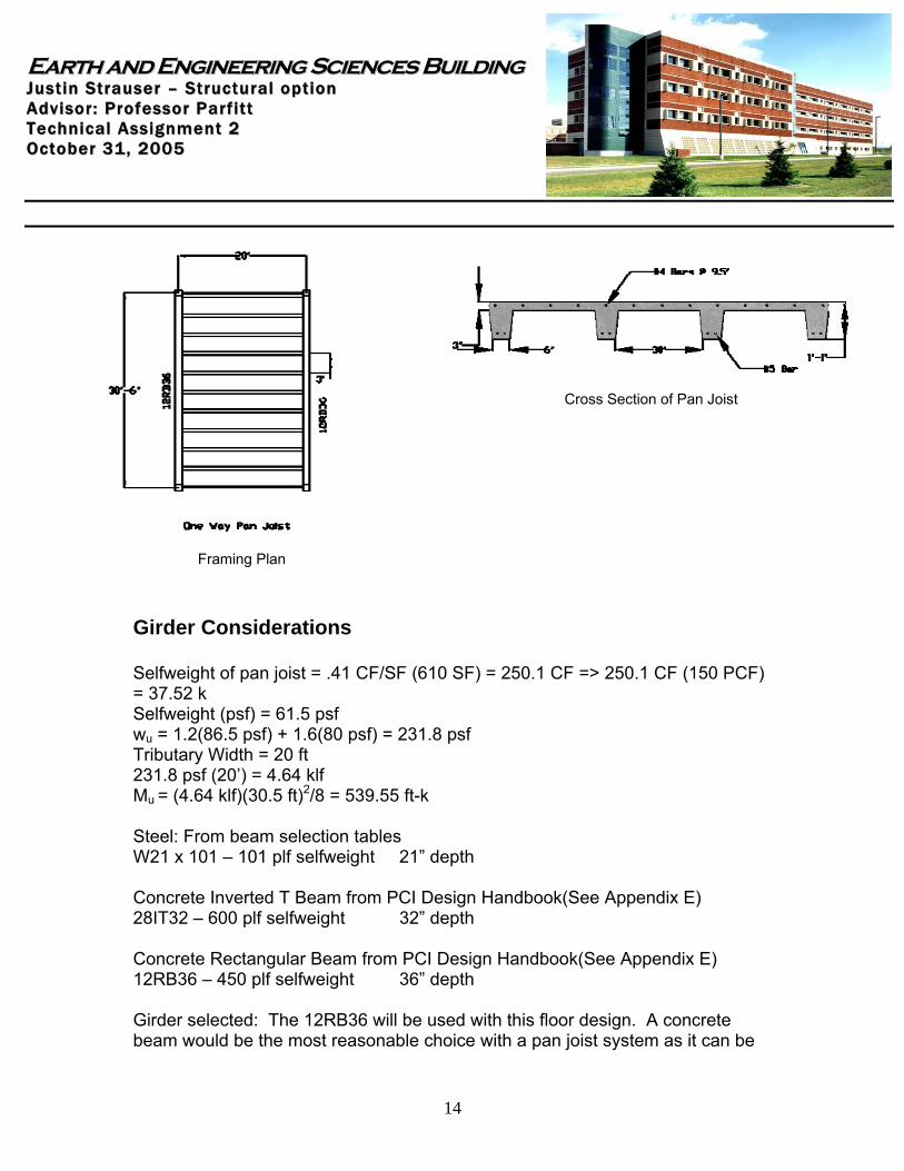
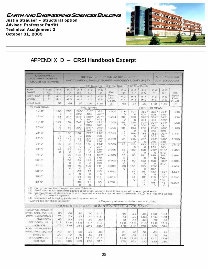
Alternate Structural Floor System 3 One Way Pan Joist The third alternate system is a concrete one way pan joist system. This system will be designed to span the short direction of 20 feet. This is a cast in place system that utilizes metal pans to create ribs that act as joists. Steel strands are placed to reinforce the top of the slab and in the bottom of the rib. When compared to previous systems, a pan joist system will be heavier due to the weight of the concrete. When contemplating the use of a pan joist floor system, scheduling must be taken under consideration and can create issues. Concrete becomes more difficult to pour at lower temperatures, and the pans need to be placed for any pours to be made. In addition, if a concrete plant is not located near the site, it can be difficult to continuously pour the system. A batch plant may need to be located on site. The benefits of this system will need to be weighted against the ability to work with constructability issues. Design wu = 1.4(25 psf) + 1.7(80 psf) = 171 psf From CRSI Tables for one way pan joists using a span of 20’ (Table can be found in Appendix D) Use pan joist with total width = 30” Forms + 6” Ribs @ 36” c.-c. Total Depth = 10” Rib + 3” slab = 13” Self weight 61.5psf f’c = 4000 psi fy = 60,000 psi Steel reinforcing (.86 psf)
1. Top - #4’s @ 9.5 “ 2. Bottom – #5, #5
Provided 209 psf > 171 psf needed
EEaarrtthh aanndd EEnnggiinneeeerriinngg SScciieenncceess BBuuiillddiinngg JJuuss tt ii nn SStt rraauuss ee rr –– SStt rruucc ttuu rraa ll oo pp tt iioo nn AA ddvv ii ssoo rr :: PPrroo ffee ssss oo rr PP aarr ff ii tt tt TT ee cchhnn ii ccaa ll AA ssss iigg nnmmee nntt 22 OO cc ttoo bbee rr 3311 ,, 22000055
14
Cross Section of Pan Joist
Framing Plan Girder Considerations Selfweight of pan joist = .41 CF/SF (610 SF) = 250.1 CF => 250.1 CF (150 PCF) = 37.52 k Selfweight (psf) = 61.5 psf wu = 1.2(86.5 psf) + 1.6(80 psf) = 231.8 psf Tributary Width = 20 ft 231.8 psf (20’) = 4.64 klf Mu = (4.64 klf)(30.5 ft)2/8 = 539.55 ft-k Steel: From beam selection tables W21 x 101 – 101 plf selfweight 21” depth Concrete Inverted T Beam from PCI Design Handbook(See Appendix E) 28IT32 – 600 plf selfweight 32” depth Concrete Rectangular Beam from PCI Design Handbook(See Appendix E) 12RB36 – 450 plf selfweight 36” depth Girder selected: The 12RB36 will be used with this floor design. A concrete beam would be the most reasonable choice with a pan joist system as it can be
EEaarrtthh aanndd EEnnggiinneeeerriinngg SScciieenncceess BBuuiillddiinngg JJuuss tt ii nn SStt rraauuss ee rr –– SStt rruucc ttuu rraa ll oo pp tt iioo nn AA ddvv ii ssoo rr :: PPrroo ffee ssss oo rr PP aarr ff ii tt tt TT ee cchhnn ii ccaa ll AA ssss iigg nnmmee nntt 22 OO cc ttoo bbee rr 3311 ,, 22000055
15
poured and constructed along with the joists. The rectangular beam is the simpler of the two concrete beams and contributes the smaller dead load to the structural system. Other Considerations Columns for this system will be the largest of all the systems as they will be required the largest load of 231.8 psf. Advantages:
Reduced depth Uniform properties aid in construction Does not require fireproofing Increases resistance to shear failure Reusable formwork
Disadvantages:
Takes longer to construct because it is a cast in place system Self weight of system is higher Needs a larger framing system to support
EEaarrtthh aanndd EEnnggiinneeeerriinngg SScciieenncceess BBuuiillddiinngg JJuuss tt ii nn SStt rraauuss ee rr –– SStt rruucc ttuu rraa ll oo pp tt iioo nn AA ddvv ii ssoo rr :: PPrroo ffee ssss oo rr PP aarr ff ii tt tt TT ee cchhnn ii ccaa ll AA ssss iigg nnmmee nntt 22 OO cc ttoo bbee rr 3311 ,, 22000055
16
Alternate Structural Floor System 4 Open Web Steel Joists
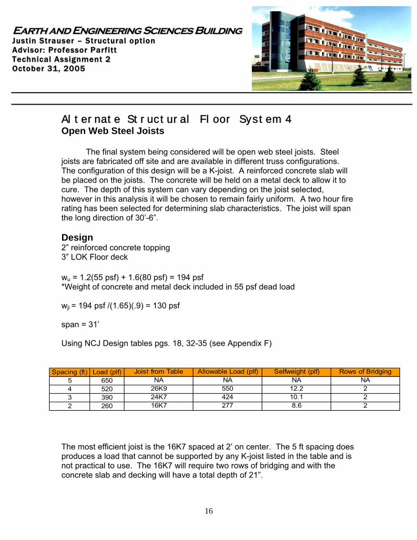
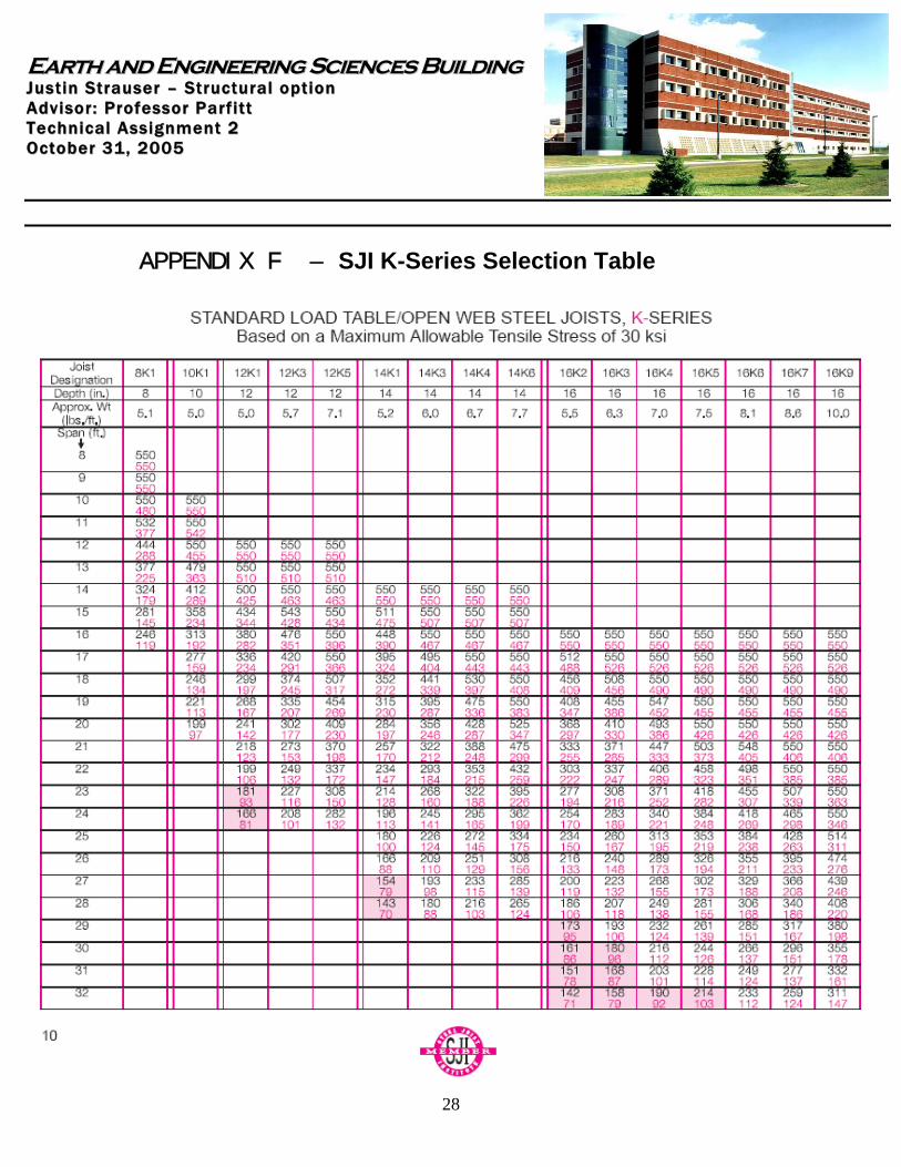
The final system being considered will be open web steel joists. Steel joists are fabricated off site and are available in different truss configurations. The configuration of this design will be a K-joist. A reinforced concrete slab will be placed on the joists. The concrete will be held on a metal deck to allow it to cure. The depth of this system can vary depending on the joist selected, however in this analysis it will be chosen to remain fairly uniform. A two hour fire rating has been selected for determining slab characteristics. The joist will span the long direction of 30’-6”. Design 2” reinforced concrete topping 3” LOK Floor deck wu = 1.2(55 psf) + 1.6(80 psf) = 194 psf *Weight of concrete and metal deck included in 55 psf dead load wji = 194 psf /(1.65)(.9) = 130 psf span = 31’ Using NCJ Design tables pgs. 18, 32-35 (see Appendix F)
The most efficient joist is the 16K7 spaced at 2’ on center. The 5 ft spacing does produces a load that cannot be supported by any K-joist listed in the table and is not practical to use. The 16K7 will require two rows of bridging and with the concrete slab and decking will have a total depth of 21”.
Spacing (ft) Load (plf)5 6504 5203 3902 260
10.1
Joist from Table
277424550NA
Allowable Load (plf)
16K7
26K9NA
8.624K7
Rows of BridgingNA222
Selfweight (plf)NA
12.2
EEaarrtthh aanndd EEnnggiinneeeerriinngg SScciieenncceess BBuuiillddiinngg JJuuss tt ii nn SStt rraauuss ee rr –– SStt rruucc ttuu rraa ll oo pp tt iioo nn AA ddvv ii ssoo rr :: PPrroo ffee ssss oo rr PP aarr ff ii tt tt TT ee cchhnn ii ccaa ll AA ssss iigg nnmmee nntt 22 OO cc ttoo bbee rr 3311 ,, 22000055
17
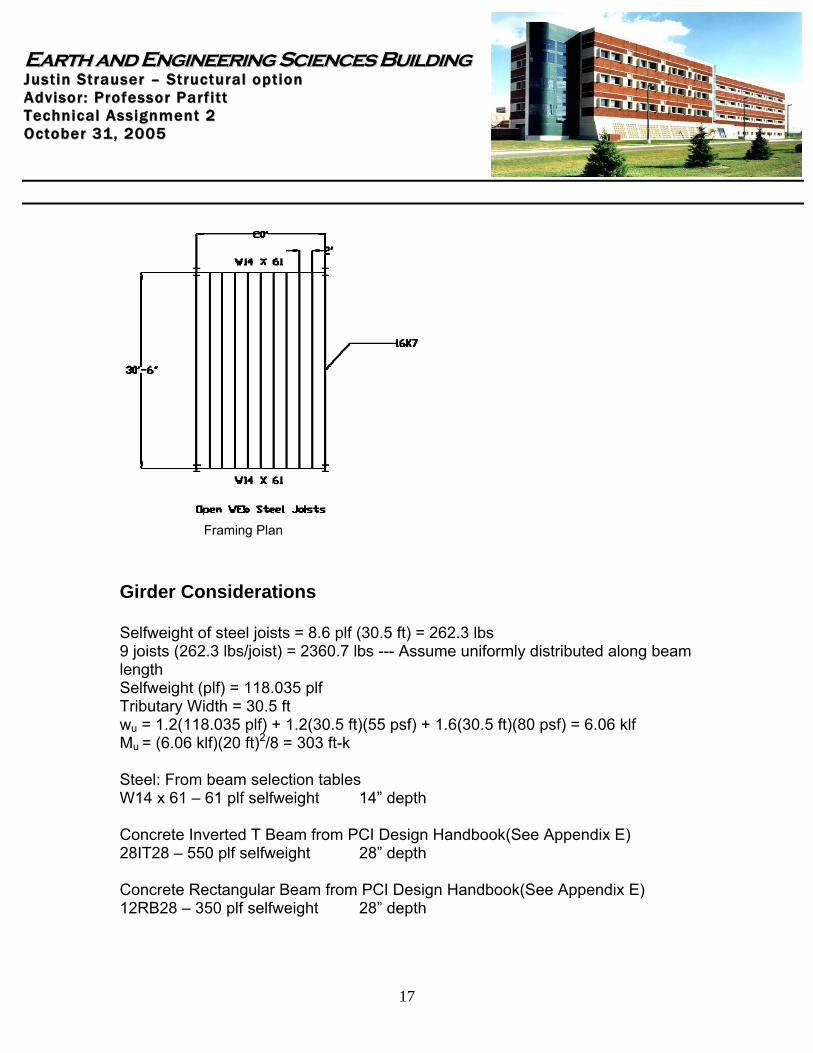
Framing Plan Girder Considerations Selfweight of steel joists = 8.6 plf (30.5 ft) = 262.3 lbs 9 joists (262.3 lbs/joist) = 2360.7 lbs --- Assume uniformly distributed along beam length Selfweight (plf) = 118.035 plf Tributary Width = 30.5 ft wu = 1.2(118.035 plf) + 1.2(30.5 ft)(55 psf) + 1.6(30.5 ft)(80 psf) = 6.06 klf Mu = (6.06 klf)(20 ft)2/8 = 303 ft-k Steel: From beam selection tables W14 x 61 – 61 plf selfweight 14” depth Concrete Inverted T Beam from PCI Design Handbook(See Appendix E) 28IT28 – 550 plf selfweight 28” depth Concrete Rectangular Beam from PCI Design Handbook(See Appendix E) 12RB28 – 350 plf selfweight 28” depth
EEaarrtthh aanndd EEnnggiinneeeerriinngg SScciieenncceess BBuuiillddiinngg JJuuss tt ii nn SStt rraauuss ee rr –– SStt rruucc ttuu rraa ll oo pp tt iioo nn AA ddvv ii ssoo rr :: PPrroo ffee ssss oo rr PP aarr ff ii tt tt TT ee cchhnn ii ccaa ll AA ssss iigg nnmmee nntt 22 OO cc ttoo bbee rr 3311 ,, 22000055
18
Girder selected: The steel W14 x 61 will be used in this. The weight, depth, and constructability of this girder makes this the best selection. Other Considerations The columns for this system will actually be reduced in size from the existing and alternate steel designs. The steel joist system transfers the smallest loading to the framing elements than each system presented. Advantages:
Excess room for supplementary systems especially mechanical Lightweight Short erection time
Disadvantages:
Deep floor system Hard to fireproof More tightly spaced Lateral loads will be increased Need lead time for fabrication Produces excess vibrations
EEaarrtthh aanndd EEnnggiinneeeerriinngg SScciieenncceess BBuuiillddiinngg JJuuss tt ii nn SStt rraauuss ee rr –– SStt rruucc ttuu rraa ll oo pp tt iioo nn AA ddvv ii ssoo rr :: PPrroo ffee ssss oo rr PP aarr ff ii tt tt TT ee cchhnn ii ccaa ll AA ssss iigg nnmmee nntt 22 OO cc ttoo bbee rr 3311 ,, 22000055
19
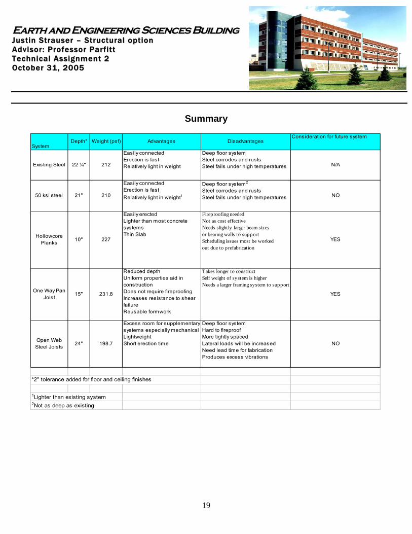
Summary
SystemDepth* Weight (psf) Advantages Disadvantages
Consideration for future system
Existing Steel 22 ¼" 212
Easily connectedErection is fastRelatively light in weight
Deep floor system Steel corrodes and rusts Steel fails under high temperatures N/A
50 ksi steel 21" 210
Easily connectedErection is fastRelatively light in weight1
Deep floor system2
Steel corrodes and rusts Steel fails under high temperatures NO
Hollowcore Planks
10" 227
Easily erectedLighter than most concrete systemsThin Slab
Fireproofing neededNot as cost effectiveNeeds slightly larger beam sizesor bearing walls to supportScheduling issues most be workedout due to prefabrication
YES
One Way Pan Joist
15" 231.8
Reduced depthUniform properties aid in constructionDoes not require fireproofingIncreases resistance to shear failureReusable formwork
Takes longer to constructSelf weight of system is higherNeeds a larger framing system to support
YES
Open Web Steel Joists
24" 198.7
Excess room for supplementary systems especially mechanicalLightweightShort erection time
Deep floor systemHard to fireproofMore tightly spacedLateral loads will be increasedNeed lead time for fabricationProduces excess vibrations
NO
*2" tolerance added for floor and ceiling finishes
1Lighter than existing system2Not as deep as existing
EEaarrtthh aanndd EEnnggiinneeeerriinngg SScciieenncceess BBuuiillddiinngg JJuuss tt ii nn SStt rraauuss ee rr –– SStt rruucc ttuu rraa ll oo pp tt iioo nn AA ddvv ii ssoo rr :: PPrroo ffee ssss oo rr PP aarr ff ii tt tt TT ee cchhnn ii ccaa ll AA ssss iigg nnmmee nntt 22 OO cc ttoo bbee rr 3311 ,, 22000055
20
Every system has multiple advantages and disadvantages to consider. Changing the grade of steel helped reduce the size of steel used, but the effects weren’t drastic and the depth was still relatively large. The alternate steel system will not be considered as a viable alternative. The concrete systems both become viable options as a system replacement. These systems both add weight to the overall structure, but the depth of the floor is greatly reduced. The added weight should not be a limiting criterion as the structure will only be four stories. The hollow core can be efficiently erected with proper planning and does not require a minimum temperature for placement. The hollow core can also rest on both steel or concrete framing members and load bearing walls. The pan joist will require planning as well in order to prevent pouring concrete in low temperatures and having the forms ready in proper sequence. One great advantage to the pan joist is the increased resistance to shear failure. Both of these systems will be considered as alternates to the current system. The final system considered was the open web steel joists. This system was discarded for a number of reasons. The fireproofing would be tough to apply. Lateral loads will be increased as well as additional vibrations in the floor. The fact that this system is lighter than the original system is one of its greatest advantages but this is overshadowed by its depth which is almost equivalent to the existing system. In conclusion the existing system was a good selection for the Earth and Engineering Sciences Building. However, upon further design and consideration it may be found that the two alternate concrete systems may be as good or better than the existing system.
EEaarrtthh aanndd EEnnggiinneeeerriinngg SScciieenncceess BBuuiillddiinngg JJuuss tt ii nn SStt rraauuss ee rr –– SStt rruucc ttuu rraa ll oo pp tt iioo nn AA ddvv ii ssoo rr :: PPrroo ffee ssss oo rr PP aarr ff ii tt tt TT ee cchhnn ii ccaa ll AA ssss iigg nnmmee nntt 22 OO cc ttoo bbee rr 3311 ,, 22000055
21
APPENDIX A – Floor Layout and Ram Output for existing floor system
EEaarrtthh aanndd EEnnggiinneeeerriinngg SScciieenncceess BBuuiillddiinngg JJuuss tt ii nn SStt rraauuss ee rr –– SStt rruucc ttuu rraa ll oo pp tt iioo nn AA ddvv ii ssoo rr :: PPrroo ffee ssss oo rr PP aarr ff ii tt tt TT ee cchhnn ii ccaa ll AA ssss iigg nnmmee nntt 22 OO cc ttoo bbee rr 3311 ,, 22000055
22
Ram Output
EEaarrtthh aanndd EEnnggiinneeeerriinngg SScciieenncceess BBuuiillddiinngg JJuuss tt ii nn SStt rraauuss ee rr –– SStt rruucc ttuu rraa ll oo pp tt iioo nn AA ddvv ii ssoo rr :: PPrroo ffee ssss oo rr PP aarr ff ii tt tt TT ee cchhnn ii ccaa ll AA ssss iigg nnmmee nntt 22 OO cc ttoo bbee rr 3311 ,, 22000055
23
APPENDIX B – Column Summary 36 ksi and 50 ksi
EEaarrtthh aanndd EEnnggiinneeeerriinngg SScciieenncceess BBuuiillddiinngg JJuuss tt ii nn SStt rraauuss ee rr –– SStt rruucc ttuu rraa ll oo pp tt iioo nn AA ddvv ii ssoo rr :: PPrroo ffee ssss oo rr PP aarr ff ii tt tt TT ee cchhnn ii ccaa ll AA ssss iigg nnmmee nntt 22 OO cc ttoo bbee rr 3311 ,, 22000055
24
APPENDIX C – Hollow core Selection
EEaarrtthh aanndd EEnnggiinneeeerriinngg SScciieenncceess BBuuiillddiinngg JJuuss tt ii nn SStt rraauuss ee rr –– SStt rruucc ttuu rraa ll oo pp tt iioo nn AA ddvv ii ssoo rr :: PPrroo ffee ssss oo rr PP aarr ff ii tt tt TT ee cchhnn ii ccaa ll AA ssss iigg nnmmee nntt 22 OO cc ttoo bbee rr 3311 ,, 22000055
25
APPENDIX D – CRSI Handbook Excerpt
EEaarrtthh aanndd EEnnggiinneeeerriinngg SScciieenncceess BBuuiillddiinngg JJuuss tt ii nn SStt rraauuss ee rr –– SStt rruucc ttuu rraa ll oo pp tt iioo nn AA ddvv ii ssoo rr :: PPrroo ffee ssss oo rr PP aarr ff ii tt tt TT ee cchhnn ii ccaa ll AA ssss iigg nnmmee nntt 22 OO cc ttoo bbee rr 3311 ,, 22000055
26
APPENDIX E – PCI Design Handbook Beam Tables
EEaarrtthh aanndd EEnnggiinneeeerriinngg SScciieenncceess BBuuiillddiinngg JJuuss tt ii nn SStt rraauuss ee rr –– SStt rruucc ttuu rraa ll oo pp tt iioo nn AA ddvv ii ssoo rr :: PPrroo ffee ssss oo rr PP aarr ff ii tt tt TT ee cchhnn ii ccaa ll AA ssss iigg nnmmee nntt 22 OO cc ttoo bbee rr 3311 ,, 22000055
27
EEaarrtthh aanndd EEnnggiinneeeerriinngg SScciieenncceess BBuuiillddiinngg JJuuss tt ii nn SStt rraauuss ee rr –– SStt rruucc ttuu rraa ll oo pp tt iioo nn AA ddvv ii ssoo rr :: PPrroo ffee ssss oo rr PP aarr ff ii tt tt TT ee cchhnn ii ccaa ll AA ssss iigg nnmmee nntt 22 OO cc ttoo bbee rr 3311 ,, 22000055
28
APPENDIX F – SJI K-Series Selection Table
EEaarrtthh aanndd EEnnggiinneeeerriinngg SScciieenncceess BBuuiillddiinngg JJuuss tt ii nn SStt rraauuss ee rr –– SStt rruucc ttuu rraa ll oo pp tt iioo nn AA ddvv ii ssoo rr :: PPrroo ffee ssss oo rr PP aarr ff ii tt tt TT ee cchhnn ii ccaa ll AA ssss iigg nnmmee nntt 22 OO cc ttoo bbee rr 3311 ,, 22000055
29
APPENDIX G – References PCI Design Handbook 5th Edition LRFD Manual of Steel Construction 3rd Edition ASD Applied in RAM software IBC 2003 Nitterhouse Prestressed Hollowcore Design Tables Steel Joist Institute Catalog CRSI Design Handbook 2002