Embed Size (px)
Citation preview
Early Experiments at the Arecibo Observatory---Cross Modulation for Measuring D-Region Electron Densities Generation of ELF/VLF
Signals by Modulating the Dynamo Current System
Presented at the 50th year anniversary of the Arecibo Observatory
Presented by A. J. Ferraro, The Pennsylvania State University
Abstract
This paper briefly summarizes the research that the Penn State University team has accomplished using
the heating facilities of the Arecibo Observatory. Heating experiments covered two broad areas. One
using the cross modulation experiment (also known as the Luxembourg effect) to measure D-region
electron densities . Originally done at the PSU heating facility and then moved to the Arecibo facilities.
The other area was involved in modulation the dynamo current system in order to generate ELF/VLF
signals useful for submarine communications.
The former data was used to support in the understanding of the physics and chemistry for the formation
of the D-region. Earlier results at Arecibo attempted to compare those results with the incoherent scatter
measurements of low-lying ionization.
The generation and measurements of the ELF/VLF signals were made at close, then moderate then much
longer paths. These will be discussed.
An important part of our program was in the design of the final heating antenna at Islote. The author,
Breakall and LaLonde were instrumental with this design. Prior to that antenna, a HF log periodic antenna
was placed above the dish and measurements proceeded for a few years in that mode until the
completion of the Islote antenna array. Due to a loss of the Islote array in a hurricane, HF heating was at
a standstill but a new antenna design by Breakall will again place an improved array above the dish to
allow future heating experiments. The modulation of the dynamo current system led to conducting the
experiment using other current systems like the equatorial electrojet and the polar electrojet. Arecibo
provided a rich environment for the PSU researchers to continue their efforts. We thank Arecibo for the
great support from all that was given to us.
Introduction
This paper briefly summarizes the research that the Penn State University team has accomplished using
the heating facilities of the Arecibo Observatory.
Heating experiments covered two broad areas. One area used the cross modulation experiment (also
known as the Luxembourg effect) to measure D-region electron densities. Originally done at the PSU
heating facility and then moved to the Arecibo facilities. The other area was involved in modulation the
dynamo current system in order to generate ELF/VLF signals useful for submarine communications. The
former data was used to support in the understanding of the physics and chemistry for the formation of
the D-region. Earlier results by John Matthews at Arecibo attempted to compare those results with the
incoherent scatter measurements of low-lying ionization.
Described briefly is the PSU program to gain insight of how activities were initiated at the Arecibo
Observatory. In the earlier 60s limited means were available for collecting large quantities of D-region
data under a host of various geophysical conditions. This led the author to review carefully ground-
based methods and improvements to the experiments. The wave interaction technique (also know as
the Luxembourg effect) was just beginning to be used by Fejer1 . This effect relies upon a higher power
radio signal (disturbing wave) to modulate the imaginary part of the index of refraction, hence affect
the absorption of a probe wave (called the wanted wave). The measured periodic amplitude
modulation upon the probe wave can be used to deduce the electron density in the D-region (with lots
of mathematical difficulty). The change incorporated by the author was to also look at the phase of the
probe wave since the real part of the index of refraction would also be affected by the disturbing wave.
The idea was that measuring both the amplitude and phase affects would double the amount of data
and lead to better results. PSU pursued this concept and installed the first heating facility on the
western hemisphere. See figure2 for the interplay of the wanted and disturbing signals.
Figures 4, 5 and 6 show the receiving unit, the 500 KW pulsed disturbing signal emitting 4.5 MHz and
the antenna array. ERP was on 11 MW, small by today’s standards but one did not want to cause
excessive disturbance to the ionosphere since the ambient ionization was desired. Figure 7 shows what
happens when one operates on 4.5 MHZ which easily propagates. FCC shuts down the facility. Arecibo
had a facility in operation so fortunately we found a home after several discussions with the director Dr.
Tor Hagfors. Above is the long story how we became frequent visitors to the Observatory.
Early Wave Interaction Operations at Arecibo
Figure 8 pictorially depicts a log periodic hanging above the dish to serve as a heater antenna. Figure 9
is a shot of the actual log periodic which suffered from corona at the ends of some of the elements. This
made operations difficult.
At Los Canos was housed, Figure 10, the wave interaction processing equipment (CM) along side of the
ELF receiving equipment to be described later. However Mike Sulzer, Figure 11, designed improved
equipment while working on his graduate studies. Mike took us from the
vacuum tube era into the solid-state era. It was a suburb piece of engineering. Figure 12 shows the
homemade wanted, or probing transmitter, which was also housed in the building at Los Canos.
Data taking continued for some time but soon sponsors thought satellites would replace the need to
employee HF prediction methods and knowledge of the ionosphere would lose its popularity and
funding. At this juncture our research direction changes course (Figure 13 says it all).
How many remember the Sexy Nightclub down the road at Los Canos?
The ELF/VLF Generation Program at Arecibo
Our sponsor requests looking for alternate ways to generate and radiate ELF/VLF signals ultimately for
submarine communications. The method that has been employed was a ground based ELF transmitting
facility at the Michigan and Wisconsin sites. 73 Hz was the frequency in use; long wire antennas, 22
miles long, were used but they were still a faction of a wavelength at 73 Hz. Never the less the
waveguide attenuation at his frequency was so low that the signal could be propagated globally. The
skin depth effect was moderately large so the signal could reach submarines at their maximum depths.
Although an ideal approach, there was great resentment by the public who equated this operation with
subs carrying nuclear weapons. The resentment grew into attacks upon the facility involving sawing
down antenna support poles and other destructive activities. Because of this the Government closed
the facility. Now the time was ripe to propose alternate methods.
The PSU team looked into generating ELF/VLF by using the natural current system in the ionosphere as a
potential radiator. At Arecibo the dynamo current is the prevalent current system in the lower part of
the ionosphere. Figure 14 shows the proposed technique. A high power HF transmitter emits pulsed
signals at the pulse rate of a desired ELF signal, let us say 1000 Hz. The HF source causes increased
absorption through which the dynamo current is passing. In simple terms, the resistance of that region
is increased and the current density diminished and some of the current density can travel the path
around the heated volume.
At any point inside or out of the heated volume the current is changed and when the heater is pulsed
off all returns to ambient conditions with some time constant. In any event the current density at these
points will be increasing and decreasing at the pulse repetition rate of 1000 Hz.
Thanks to Maxwell the heated region and surrounding region must radiate. Thus a 1000 Hz signal and
its harmonics radiate into the earth ionosphere waveguide and propagated there in.
Figure 15 shows a map of the dynamo current, with 10,000 amperes between the lines. Current
densities diminish at night and are stronger by day as one can deduced from the Figure. Figure 16
summarizes the simple picture of generating a time varying signal from a modulated dynamo current
system.
The Islote Heating Antenna array
The heater array at Islote was used in the ELF/VLF generation research program (Figure 17). The array
got its start from initial meetings between Breakall, LaLonde and the author. Several designs were
considered but the one finally chosen was an array of inverted log periodic dipole
elements. Figure 18 is a partial view of the maze of wires. That is Breakall in the picture. Figure 19
shows the younger Breakall! Little did he realize at that time that he would become one of the best
antenna designers known in the community and an asset to the Observatory. Figures 20 and 21 are
further views of the structure. Aiding in managing the erection of the array was Al Veldise, a retired
antenna engineer
from AEL corporation and a new graduate student from PSU, Chris Trask. Figure 22 is the remains of the
array after a hurricane. I believe the towers are no longer there. Breakall will describe his newest heater
antenna.
Measurements of ELF/VLF over Several Paths
A lot of data was taken under local conditions, i.e., the ELF/VLF receiving equipment at Los Canos was
nearby the heating source at Islote. It was clear that the method worked and data could be
reproduced. The ELF/VLF signal was present during the daytime, disappeared at night since the
dynamo current was weaker at night and there was less D, E region absorption to make the depth of
modulation strong. It was now time to reach out further.
We had hoped to have shipboard measurements by spinning around the Island trying to estimate the
pattern of the radiation but our sponsors suggested a cruise ship. Cruise ships don’t take you were you
wish to go unless for a vacation! We had a complex full wave model of the fields expected in the earth
ionosphere waveguide due to an imbedded dipole in the ionosphere, Carroll2 et al. Figure 24 shows a
path for which 2 weeks of measurements were successfully accomplished. Figure 25 shows Tom Collins
making the shipboard measurements using a ELF/VLF loop antenna.
Next we tried a very long path; Islote to the field site, Scotia, at the PSU receiving site for a distance of
1675 miles. The signal to be generated was a simple binary message, 1011. The heater transmitters
were modulated with a sine wave instead of a pulse. By shifting the modulating signal 180 degrees and
back to zero degrees we could create the binary quantities “1” or “0”. Correlation measurements
clearly showed the four bits were received correctly. However some in the scientific community
thought this could not be true. We conducted several tests to convince ourselves that it was a real
effect. It gave me thought of Alexander von Humboldt’s statement, shown on Figure 28. The event is
denied as true, then denied it is important, finally they credit the wrong person. Many of you might
have had this feeling about your scientific endeavors.
Achievements at other Heating Facilities
A brief description of research at other heating facilities follows.
The ONR provides funding, Figure 29, to examine ELF/VLF generation with a polar electrojet (PEJ) and
the equatorial electrojet (EEJ). HIPAS in Fairbanks, AK provided the first opportunity to evaluate
generation with a PEJ. The PEJ can be very strong and provided higher field strengths of generation
than from the dynamo current. However it is not predictable.
The HIPAS facility heater array was a set of 7 dipoles, six equally positioned on a circle and one in the
center. Transmitters fed each dipole. One could phase the elements to create different HF patterns.
One in particular was a double main beam with about 20 degrees between centers of the beams. Thus
creating a two element ELF/VLF antenna from the modulation of the current system. Further by shifting
the phases of the elements to its neighboring elements causes a rotation of the two heated regions
because of the circular symmetry of the heater array. Thus one can step the locations of the two heater
beams around a circle. As to be expected the direction of the generated signal could be made to point
in different azimuthal directions. A mobile ELF/VLF receiver was positioned 290 miles from HIPAS as
shown in Figure 30. One could correlate the strengths of the received signal with angular positions of
the two element ELF/VLF array in the ionosphere. Since submarine communications was an objective,
being able to direct t he signal seemed like an important point t consider. The HIPAS array did not
permit more than two heated regions but future arrays could be designed to create a larger ELF/VLF
array. The EEJ was tested at Jicamarca, Peru even though the heating frequency was far from being optimized
for heating but it did work. See Figure 31. Signals were weak but they were generated.
Finally HAARP was funded, Figure 32, a facility in AK. Penn state did not do any generation experiments
there but Breakall, Collins and Ferraro played a role in the design, modeling, and testing of scale
models. Figure 33 shows the final HF array with 12 by 15 elements.
Figure 34 shows the typical loop antennas used to receive the ELF/VLF signal, modest by comparison to
heater arrays.
Figure 35 shows the ERP in dBw for various facilities.
This has been a brief overview of the work done at Arecibo and we wish to thank all staff that provided
for the assistance to make our experiments successful.
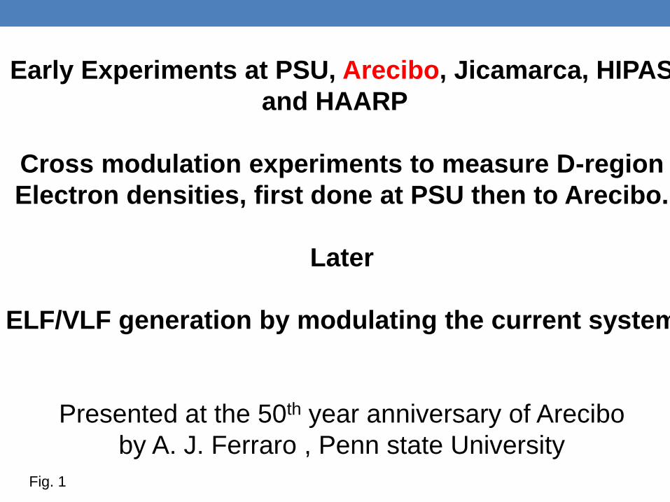
Early Experiments at PSU, Arecibo, Jicamarca, HIPAS
and HAARP
Cross modulation experiments to measure D-region
Electron densities, first done at PSU then to Arecibo.
Later
ELF/VLF generation by modulating the current system
Presented at the 50th year anniversary of Arecibo
by A. J. Ferraro , Penn state University
Fig. 1
Penn States involvement with D-region heating began in 1963 with
the pulsed cross-modulation experiment.
Our interest was with measuring the normal D-region electron
densities and better understanding the physic of formation
of the D-region.
Later, 1980, we began ELF/VLF generation
At AO
Fig 2
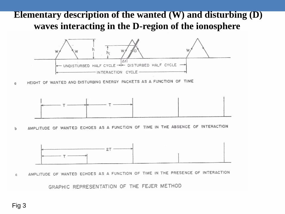
Elementary description of the wanted (W) and disturbing (D)
waves interacting in the D-region of the ionosphere
Fig 3

THE PSU CROSS-MODULATION
RECEIVING UNIT
Fig 4
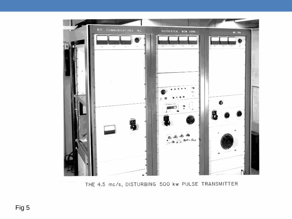
Fig 5
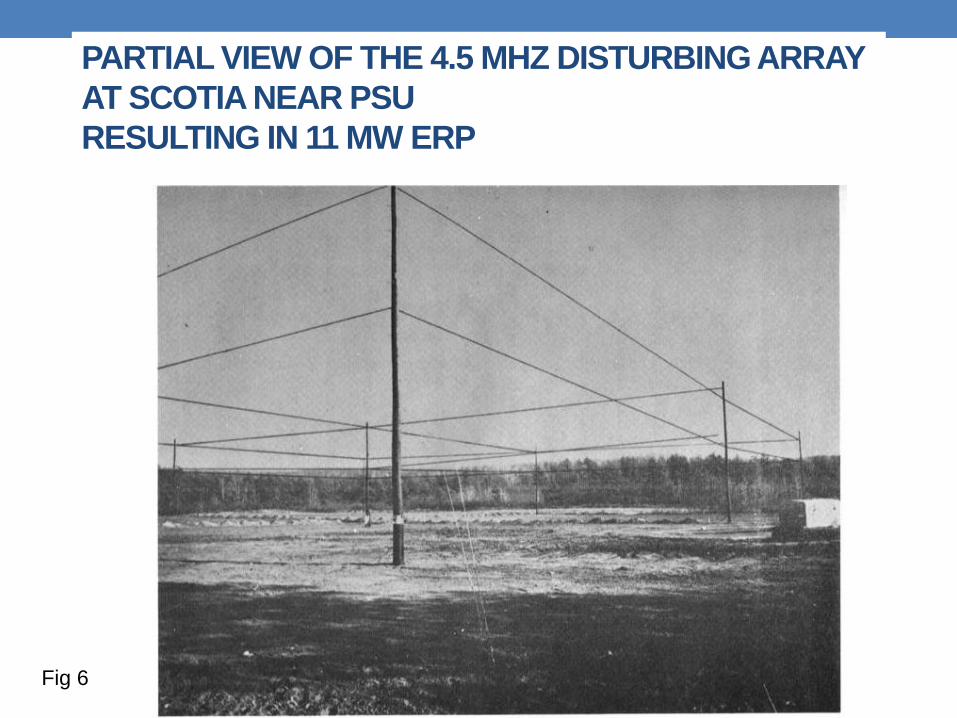
PARTIAL VIEW OF THE 4.5 MHZ DISTURBING ARRAY
AT SCOTIA NEAR PSU
RESULTING IN 11 MW ERP
Fig 6
THE FCC SHUTS US DOWN, WE
INTERFERRED WITH TOO MANY OTHER
SERVICES.
WE MOVED TO ARECIBO , PUERTO RICO
TO CONTINUE.
OUR RECEIVING EQUIPMENT IS
REDESIGNED AND WE MAKE USE OF
HEATERS AND ANTENNAS
AT ARECIBO
Fig 7
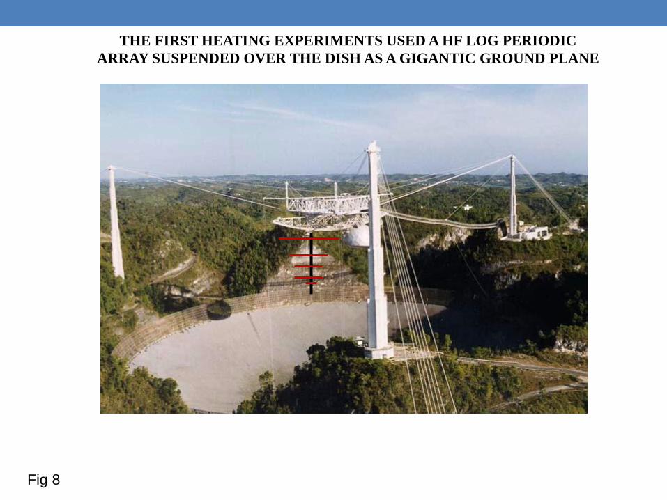
THE FIRST HEATING EXPERIMENTS USED A HF LOG PERIODIC
ARRAY SUSPENDED OVER THE DISH AS A GIGANTIC GROUND PLANE
Fig 8
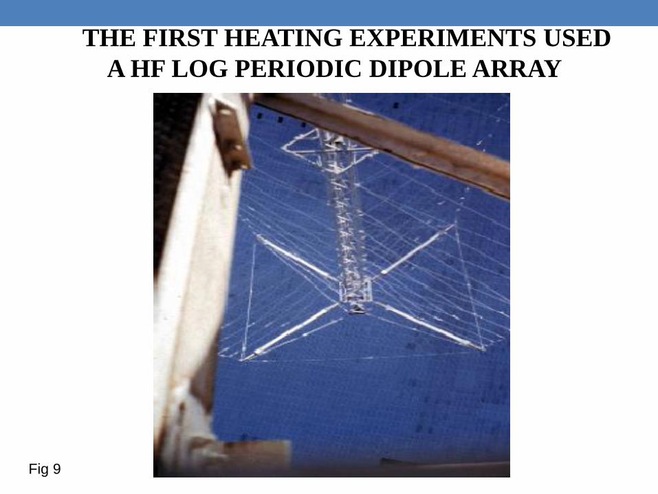
THE FIRST HEATING EXPERIMENTS USED
A HF LOG PERIODIC DIPOLE ARRAY
Fig 9
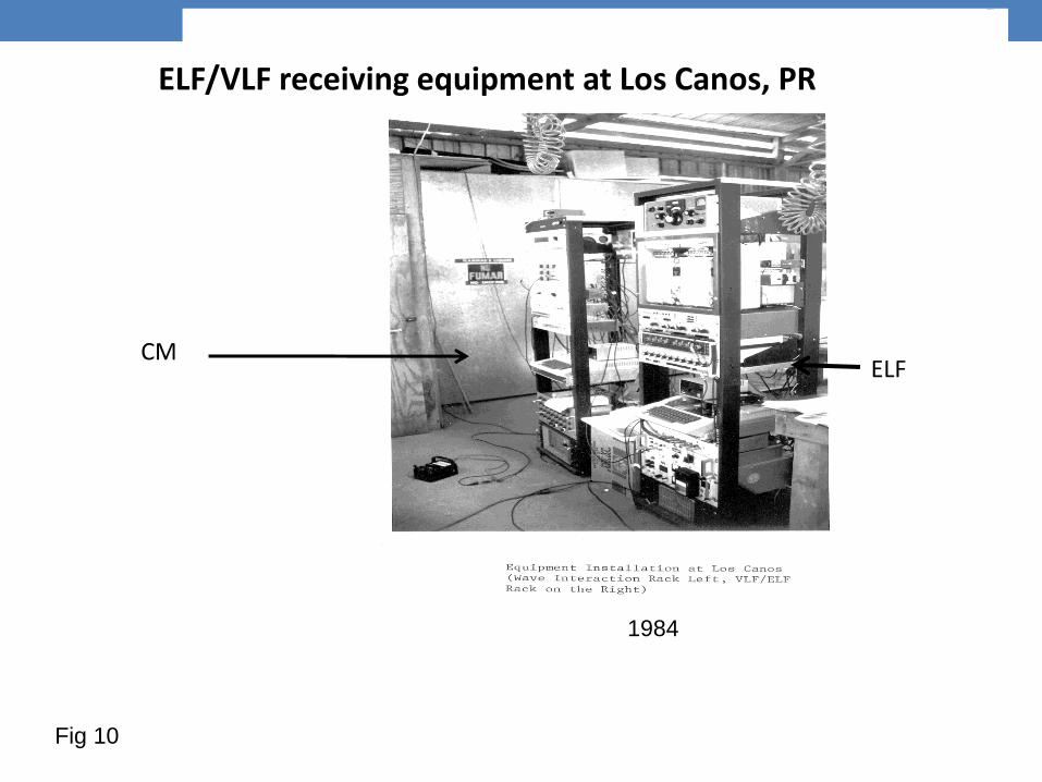
ELF/VLF receiving equipment at Los Canos, PR
ELF CM
1984
Fig 10
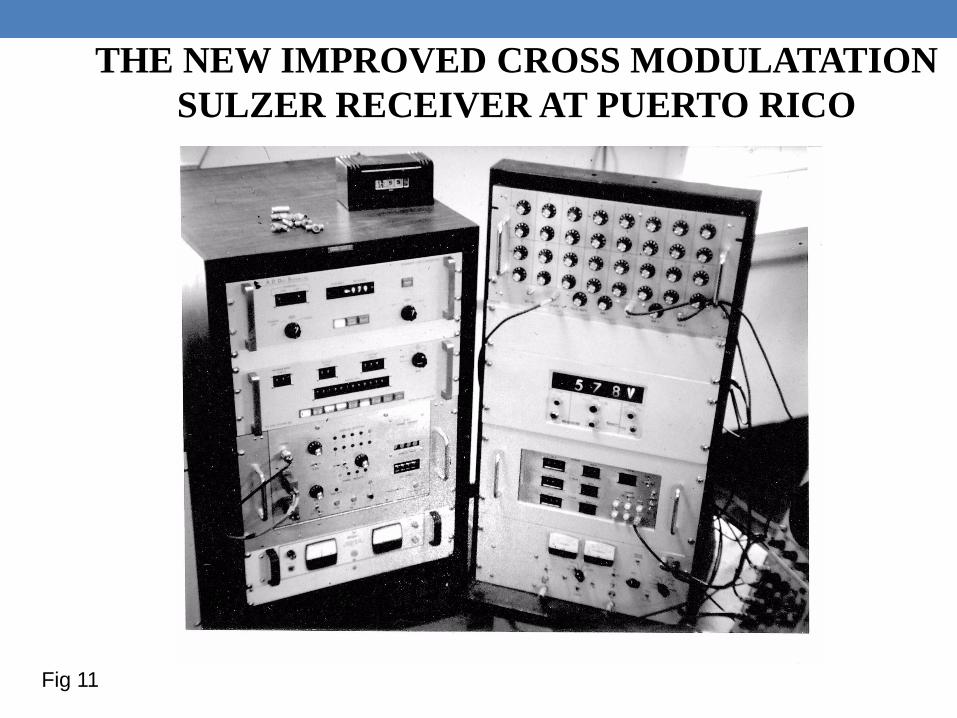
THE NEW IMPROVED CROSS MODULATATION
SULZER RECEIVER AT PUERTO RICO
Fig 11
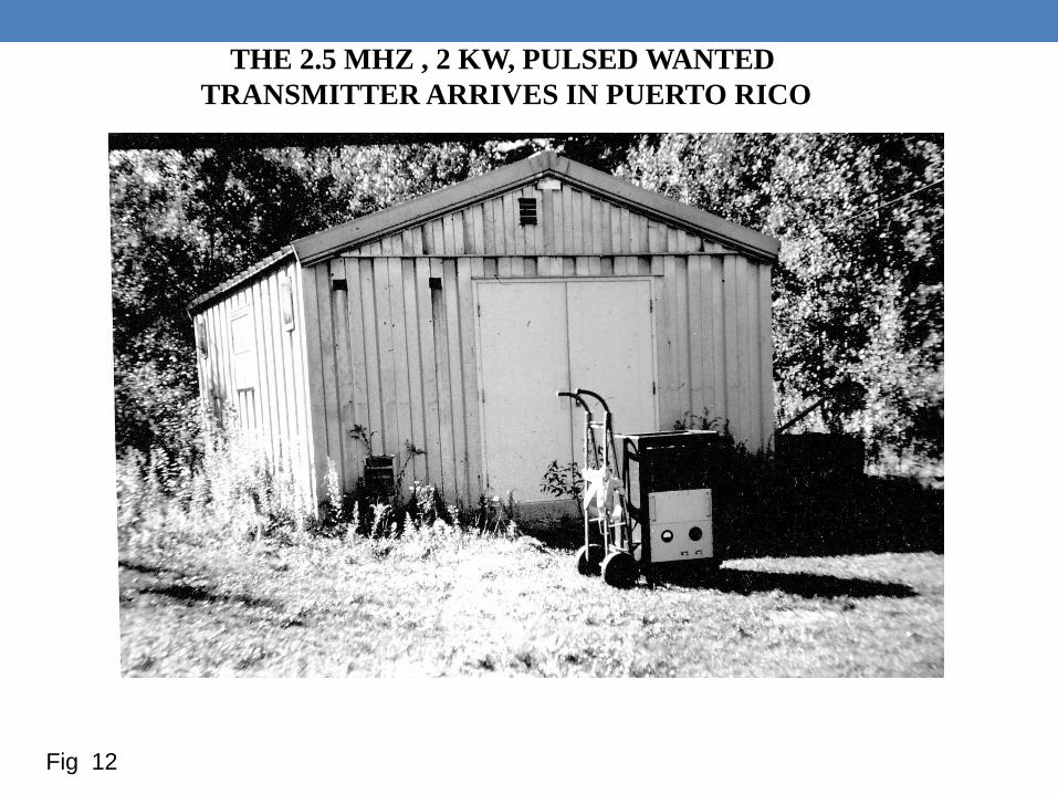
THE 2.5 MHZ , 2 KW, PULSED WANTED
TRANSMITTER ARRIVES IN PUERTO RICO
Fig 12
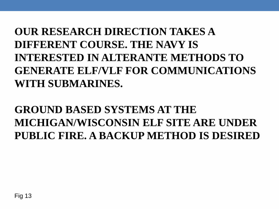
OUR RESEARCH DIRECTION TAKES A
DIFFERENT COURSE. THE NAVY IS
INTERESTED IN ALTERANTE METHODS TO
GENERATE ELF/VLF FOR COMMUNICATIONS
WITH SUBMARINES.
GROUND BASED SYSTEMS AT THE
MICHIGAN/WISCONSIN ELF SITE ARE UNDER
PUBLIC FIRE. A BACKUP METHOD IS DESIRED
Fig 13
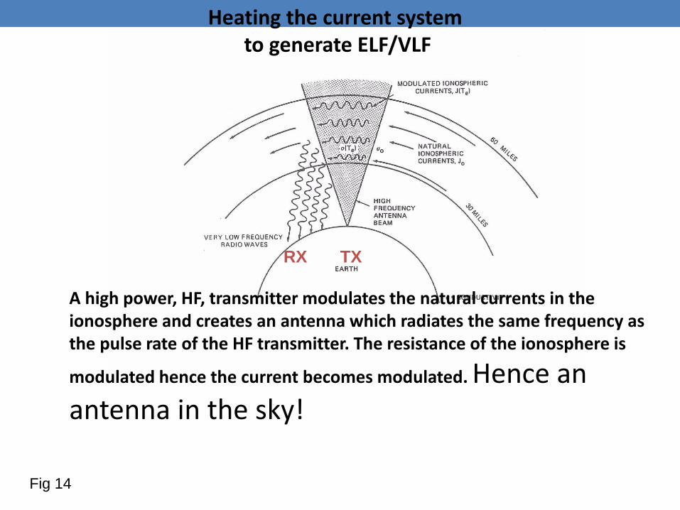
Heating the current system to generate ELF/VLF
A high power, HF, transmitter modulates the natural currents in the ionosphere and creates an antenna which radiates the same frequency as the pulse rate of the HF transmitter. The resistance of the ionosphere is
modulated hence the current becomes modulated. Hence an antenna in the sky!
RX TX
Fig 14
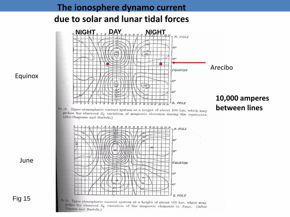
Arecibo
The ionosphere dynamo current due to solar and lunar tidal forces
10,000 amperes between lines
Equinox
June
DAY NIGHT NIGHT
Fig 15
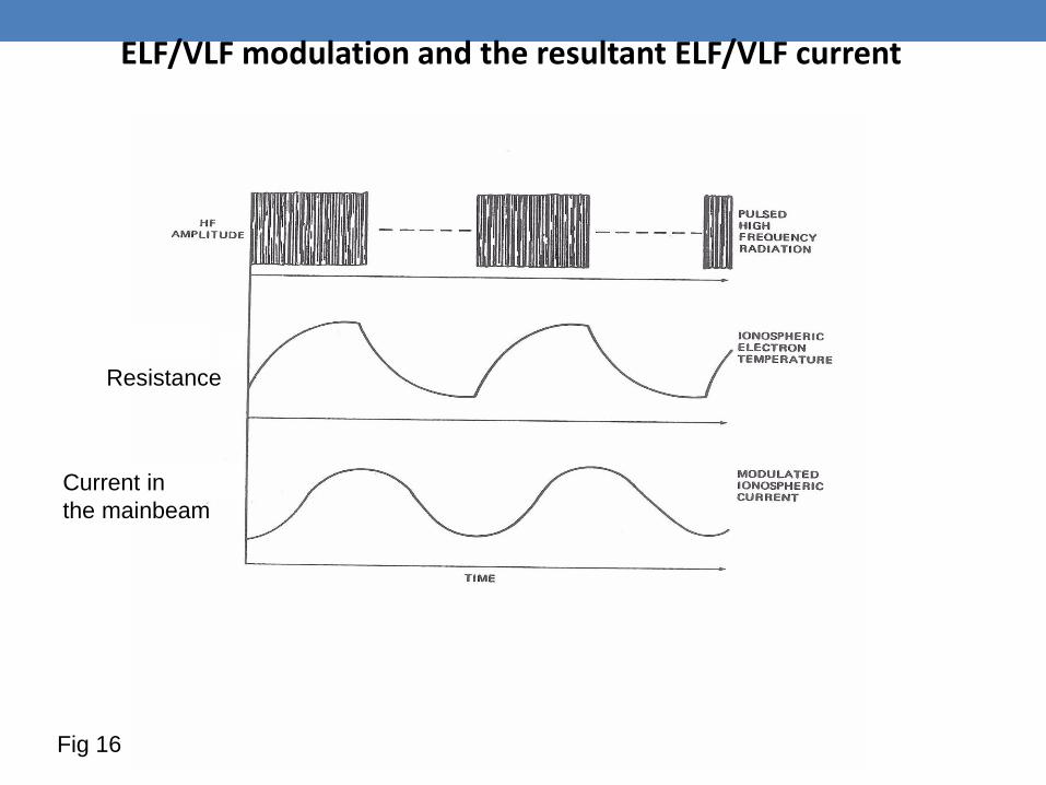
ELF/VLF modulation and the resultant ELF/VLF current
Te
J(Te)
Resistance
Current in
the mainbeam
Fig 16
A NEW HEATING FACILITY IS FUNDED
AT THE ARECIBO OBSERVATORY.
THE RADIO ASTRONOMERS
DON’T WANT TO PUT UP WITH
THE IONOSPHERE TYPES
PUTTING XMAS DECORATIONS ON
THE DISH.
IRL DESIGNS THE ANTENNA ARRAY
(Breakall, LaLonde and Ferraro)
Fig 17
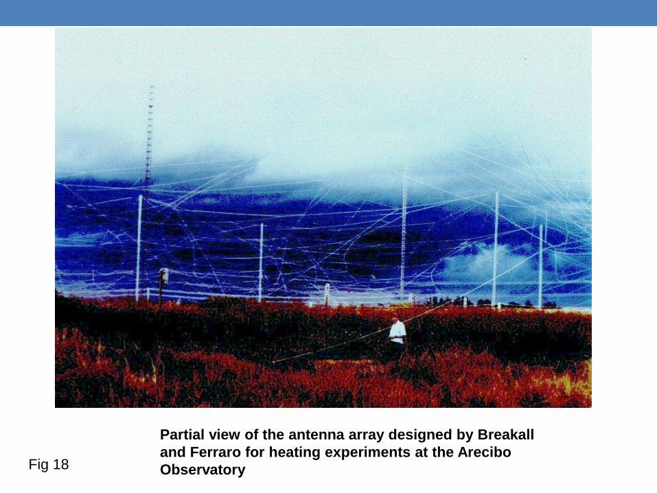
Partial view of the antenna array designed by Breakall
and Ferraro for heating experiments at the Arecibo
Observatory Fig 18
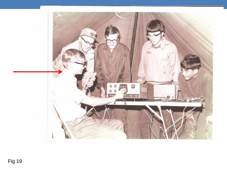
Fig 19
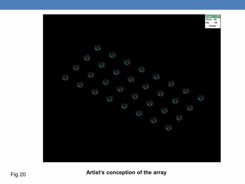
Artist’s conception of the array Fig 20
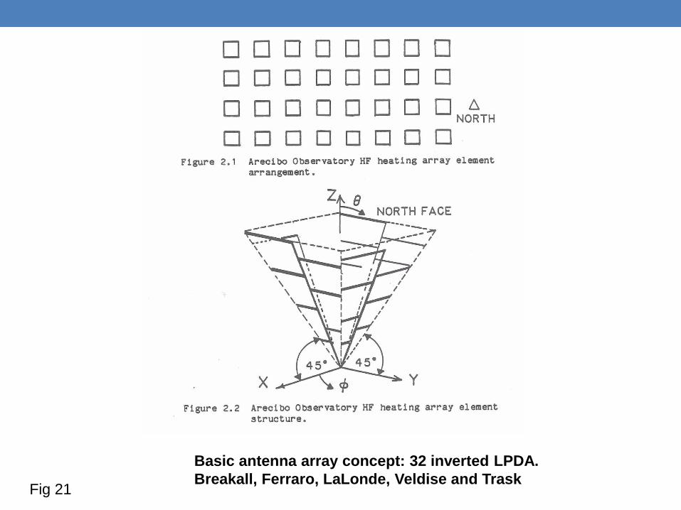
Basic antenna array concept: 32 inverted LPDA.
Breakall, Ferraro, LaLonde, Veldise and Trask Fig 21
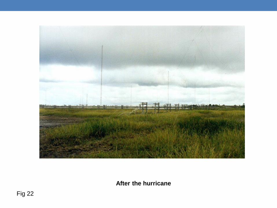
After the hurricane
Fig 22
We now expand our measurement program from local measurements to longer and even longer paths. Ship board measurements around the Caribbean and finally the long path from Arecibo to State College and other paths.
Fig 23
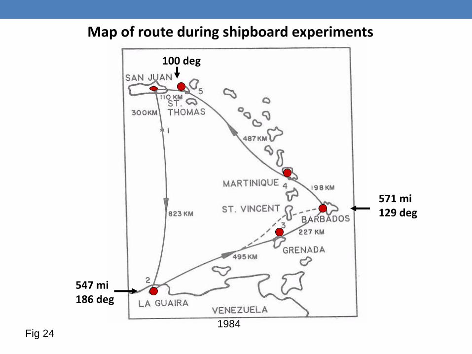
Map of route during shipboard experiments
547 mi 186 deg
571 mi 129 deg
100 deg
1984 Fig 24
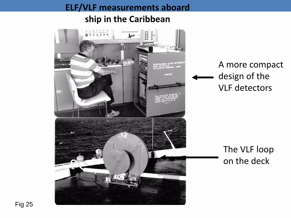
ELF/VLF measurements aboard ship in the Caribbean
A more compact design of the VLF detectors
The VLF loop on the deck
Fig 25
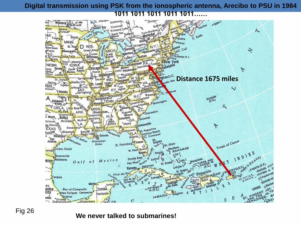
Digital transmission using PSK from the ionospheric antenna, Arecibo to PSU in 1984
1011 1011 1011 1011 1011……
Distance 1675 miles
We never talked to submarines! Fig 26
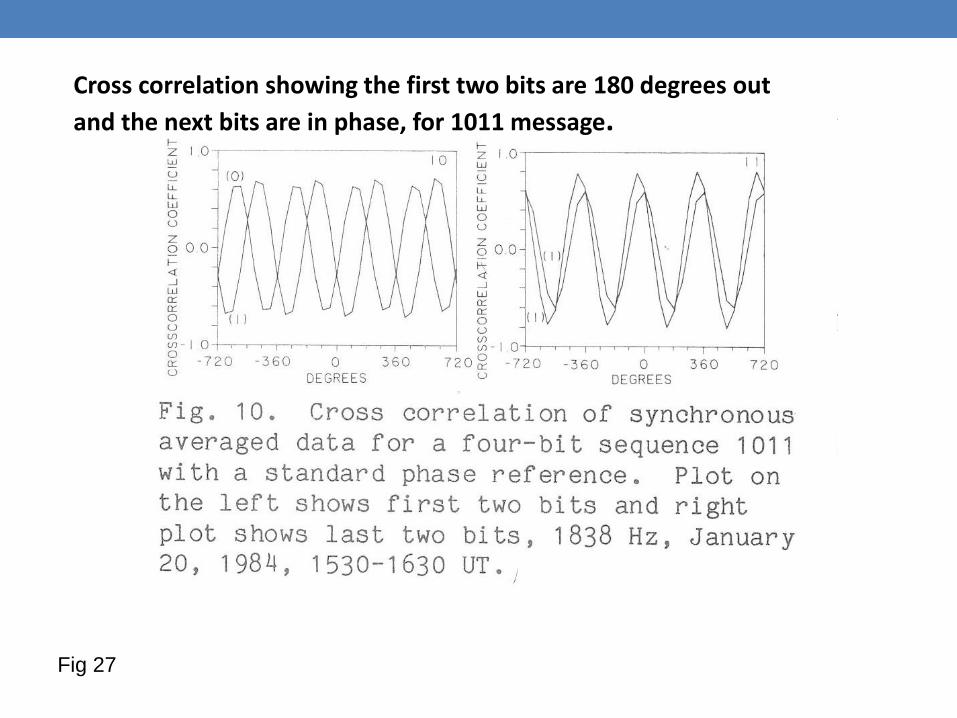
Cross correlation showing the first two bits are 180 degrees out
and the next bits are in phase, for 1011 message.
Fig 27

Alexander von Humboldt observed that there are three stages in
scientific discovery: first people deny that it is true; then they deny that it
is important; finally they credit the wrong person.
—cited in A Short History of Nearly Everything, by Bill Bryson, p. 421
Fig 28
HIPAS* heating facility comes on line
in Fairbanks , Alaska.
Here is an opportunity to explore using
the PEJ current system as the current
source to generate ELF/VLF.
A contract with ONR gives PSU the
responsibility to evaluate the generation
capabilities from the PEJ.
*High Power Auroral Simulation
Fig 29
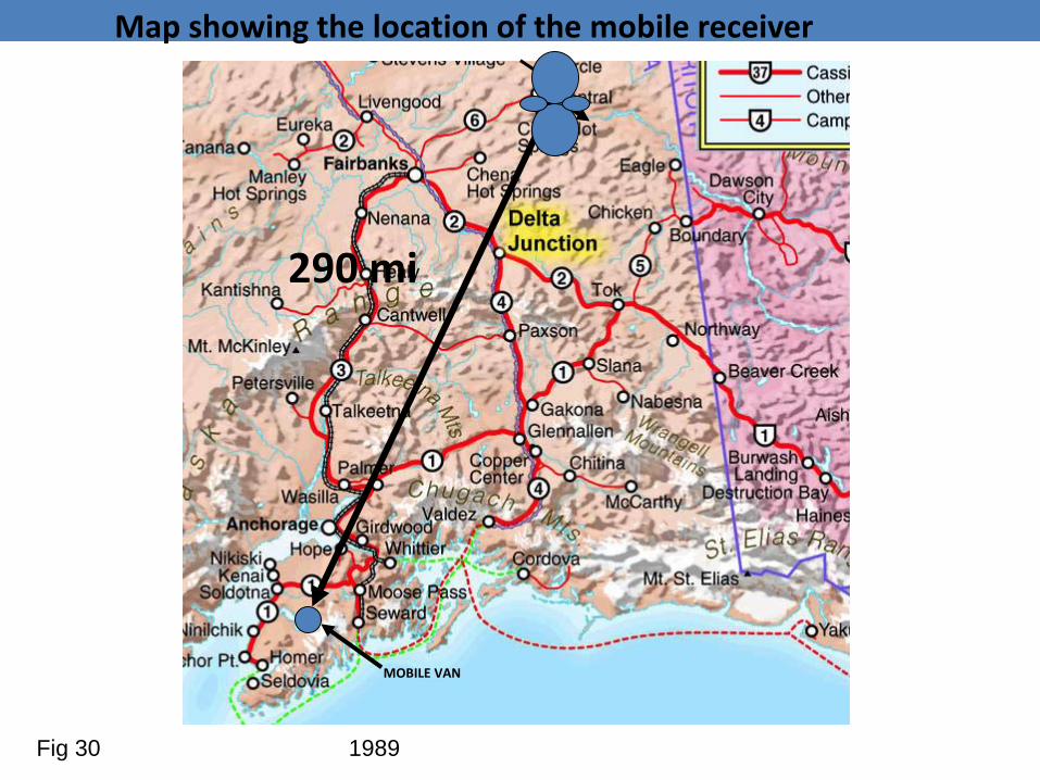
MOBILE VAN
Map showing the location of the mobile receiver
290 mi
1989 Fig 30
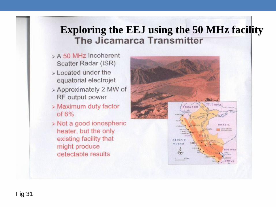
Exploring the EEJ using the 50 MHz facility
Fig 31
HAARP*
The ONR/AFRL funds an even larger heating facility located between Fairbanks and Anchorage. PSU plays a role with APTI in the design of this array
* High Frequency Active Auroral Research Program
Fig 32
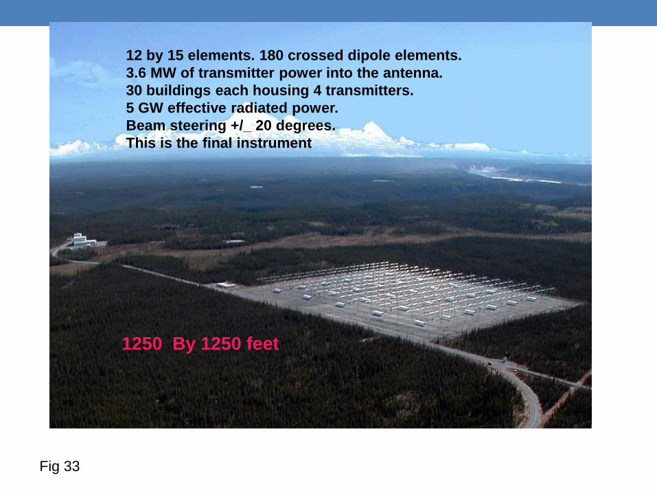
12 by 15 elements. 180 crossed dipole elements.
3.6 MW of transmitter power into the antenna.
30 buildings each housing 4 transmitters.
5 GW effective radiated power.
Beam steering +/_ 20 degrees.
This is the final instrument
1250 By 1250 feet
Fig 33
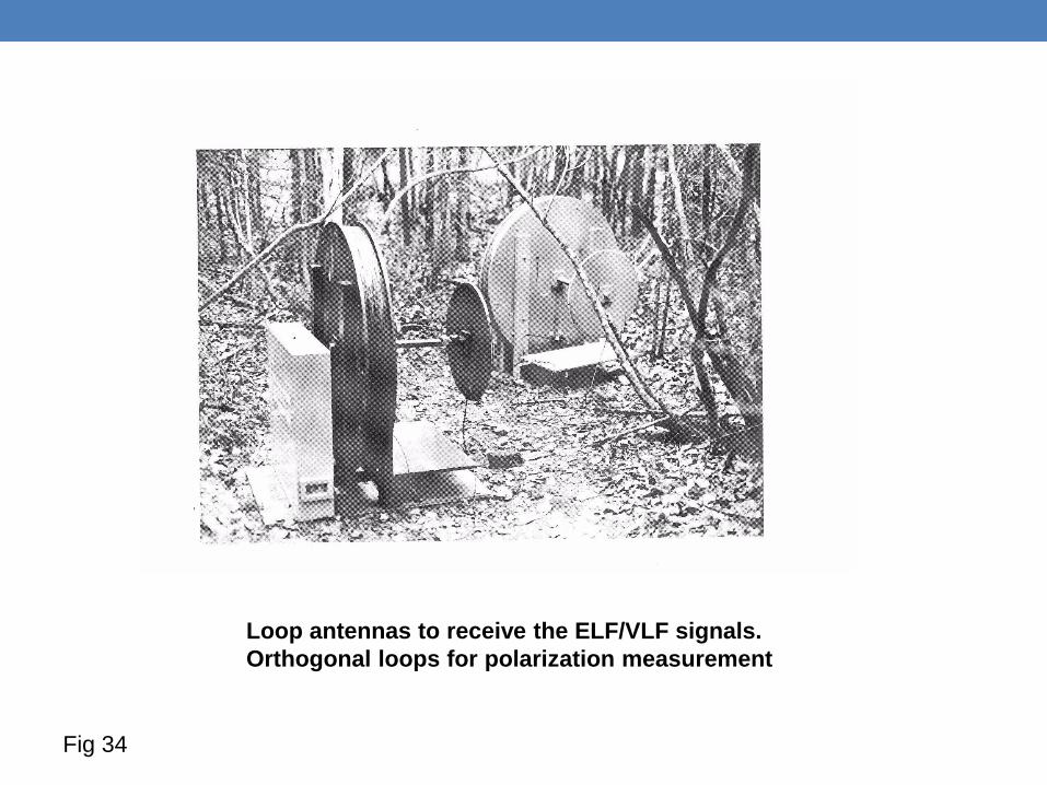
Loop antennas to receive the ELF/VLF signals.
Orthogonal loops for polarization measurement
Fig 34
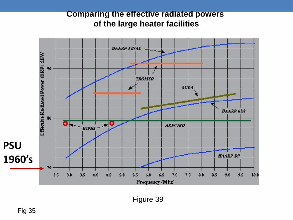
Comparing the effective radiated powers
of the large heater facilities
PSU 1960’s
Figure 39
Fig 35