Embed Size (px)
Citation preview

December 2014
L a w r e n c e L i v e r m o r e N a t i o n a l L a b o r a t o r y
A Weapon Test at Supersonic Speed
Also in this issue:
A Model for Sustainability
Crystal Orientation Mapping
NuSTAR Looks at Neutron Stars
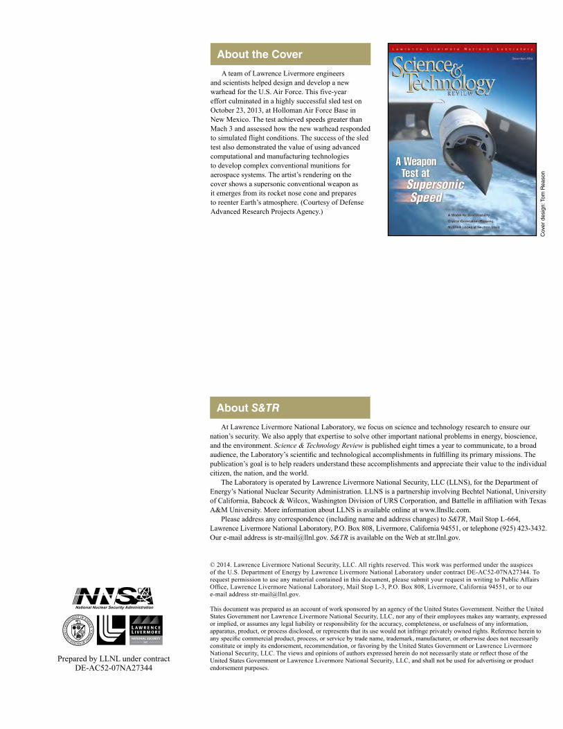
About the Cover
Cov
er d
esig
n: T
om R
easo
n
About S&TR
At Lawrence Livermore National Laboratory, we focus on science and technology research to ensure our nation’s security. We also apply that expertise to solve other important national problems in energy, bioscience, and the environment. Science & Technology Review is published eight times a year to communicate, to a broad audience, the Laboratory’s scientific and technological accomplishments in fulfilling its primary missions. The publication’s goal is to help readers understand these accomplishments and appreciate their value to the individual citizen, the nation, and the world. The Laboratory is operated by Lawrence Livermore National Security, LLC (LLNS), for the Department of Energy’s National Nuclear Security Administration. LLNS is a partnership involving Bechtel National, University of California, Babcock & Wilcox, Washington Division of URS Corporation, and Battelle in affiliation with Texas A&M University. More information about LLNS is available online at www.llnsllc.com. Please address any correspondence (including name and address changes) to S&TR, Mail Stop L-664, Lawrence Livermore National Laboratory, P.O. Box 808, Livermore, California 94551, or telephone (925) 423-3432. Our e-mail address is [email protected]. S&TR is available on the Web at str.llnl.gov.
© 2014. Lawrence Livermore National Security, LLC. All rights reserved. This work was performed under the auspices of the U.S. Department of Energy by Lawrence Livermore National Laboratory under contract DE-AC52-07NA27344. To request permission to use any material contained in this document, please submit your request in writing to Public Affairs Office, Lawrence Livermore National Laboratory, Mail Stop L-3, P.O. Box 808, Livermore, California 94551, or to our e-mail address [email protected].
This document was prepared as an account of work sponsored by an agency of the United States Government. Neither the United States Government nor Lawrence Livermore National Security, LLC, nor any of their employees makes any warranty, expressed or implied, or assumes any legal liability or responsibility for the accuracy, completeness, or usefulness of any information, apparatus, product, or process disclosed, or represents that its use would not infringe privately owned rights. Reference herein to any specific commercial product, process, or service by trade name, trademark, manufacturer, or otherwise does not necessarily constitute or imply its endorsement, recommendation, or favoring by the United States Government or Lawrence Livermore National Security, LLC. The views and opinions of authors expressed herein do not necessarily state or reflect those of the United States Government or Lawrence Livermore National Security, LLC, and shall not be used for advertising or product endorsement purposes.
Prepared by LLNL under contractDE-AC52-07NA27344
A team of Lawrence Livermore engineers and scientists helped design and develop a new warhead for the U.S. Air Force. This five-year effort culminated in a highly successful sled test on October 23, 2013, at Holloman Air Force Base in New Mexico. The test achieved speeds greater than Mach 3 and assessed how the new warhead responded to simulated flight conditions. The success of the sled test also demonstrated the value of using advanced computational and manufacturing technologies to develop complex conventional munitions for aerospace systems. The artist’s rendering on the cover shows a supersonic conventional weapon as it emerges from its rocket nose cone and prepares to reenter Earth’s atmosphere. (Courtesy of Defense Advanced Research Projects Agency.)
S&TR Staff
Lawrence Livermore National Laboratory
Scientific editor
Gregory C. Burton
Managing editor
Ray Marazzi
Publication editor
Carolin Middleton
WriterS
Rose Hansen, Arnie Heller, Malone R. Locke, and Caryn Meissner
art director
Tom Reason
ProofreaderS
Pamela MacGregor and Ann Parker
Print coordinator
Charlie M. Arteago, Jr.
S&TR, a Director’s Office publication, is produced by the Technical Information Department under the direction of the Office of Planning and Special Studies.
S&TR is available on the Web at str.llnl.gov.
Printed in the United States of America
Available fromNational Technical Information ServiceU.S. Department of Commerce5285 Port Royal RoadSpringfield, Virginia 22161
UCRL-TR-52000-14-12Distribution Category UC-99December 2014
Research Highlights
December 2014
2 The Laboratory in the News
24 Patents and Awards
27 2014 Index
29 Abstract
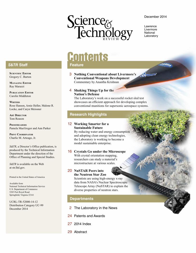
12 Working Smarter for a Sustainable Future
By reducing water and energy consumption and adopting clean energy technologies, the Laboratory is working to become a model sustainable enterprise.
16 Crystals Go under the MicroscopeWith crystal orientation mapping, researchers can study a material’s microstructure at various scales.
20 NuSTAR Peers into the Neutron Star Zoo
Scientists are using high-energy x-ray data from NASA’s Nuclear Spectroscopic Telescope Array (NuSTAR) to explain the diverse properties of neutron stars.
3 Nothing Conventional about Livermore’s Conventional Weapons Development
Commentary by Anantha Krishnan
4 Shaking Things Up for the Nation’s Defense
The Laboratory’s work on a successful rocket sled test showcases an efficient approach for developing complex conventional munitions for supersonic aerospace systems.
Feature
Departments
Contents

The Laboratory in the News S&TR December 2014
2 Lawrence Livermore National Laboratory
The Field-Effect Transistor Goes 3DScientists from Lawrence Livermore and the Karlsruhe Institute
of Technology in Germany have shown that the underlying principle of the field-effect transistor (FET), which revolutionized electronic equipment, can be extended from semiconducting thin films to metallic three-dimensional (3D) materials. By applying electrochemically induced variations in surface charge, they were able to dynamically control the electrical conductivity of centimeter-sized, bulk nanographene samples. Their results were featured on the cover of the June 18, 2014, issue of Advanced Functional Materials.
For this study, researchers filled the pores of a nanoporous bulk material with an electrolyte and imposed a gate potential of less than 1 volt. In the process, they achieved fully reversible changes in conductance of several hundred percent throughout the entire volume of the bulk electrode. The observed conductivity change resulted from the electrochemically induced accumulation or depletion of charge carriers in combination with the large variation in the carrier mobility.
Materials that alter their properties in response to changes in their surface charge are of interest for various electronic applications. A FET, for example, uses an external electric field to control the charge-carrier density and thus conductivity of a semiconducting material. Bulk nanographene has an ultrahigh surface area and is chemically inert, important characteristics for using surface charge to modulate physical properties. The results will allow researchers to explore using bulk graphene materials in such applications as low-voltage, high-power tunable resistors.Contact: Juergen Biener (925) 422-9081 ([email protected]).
Calculating Conditions at the Birth of the UniverseAn international collaboration called HotQCD, which was
led by Livermore physicists, has calculated the properties of the quantum chromodynamics (QCD) phase transition, simulating conditions that occurred during the first microseconds of the big bang. The computationally intensive calculation was supported by the Laboratory’s Computing Grand Challenge Program, which allocates time on high-performance computing systems for compelling large-scale projects such as the one performed by the HotQCD collaboration. Results from the team’s research appeared in the August 18, 2014, edition of Physical Review Letters.
When the universe was less than 1 microsecond old and at a temperature of more than 1 trillion degrees, it transformed from a plasma of quark and gluon particles into bound states of particles known as protons and neutrons. QCD theory, which describes the interactions of quarks and gluons and the strong nuclear forces between protons and neutrons, predicts such a transition during the extreme conditions at the birth of the universe. To calculate the phase transition, the HotQCD team used
Livermore’s Vulcan supercomputer, an IBM BlueGene/Q machine that can process up to 5 quadrillion floating-point operations per second (petaflops). With the team’s new algorithm, the researchers could, for the first time, run the calculation in a way that preserves a fundamental symmetry of QCD in which left- and right-handed (or chiral) quarks can be interchanged without altering the equations.
In a 2007 essay in Computing in Science & Engineering, Livermore scientists Ron Soltz and Pavlos Vranas predicted that the QCD phase transition could be calculated given powerful enough computers. “With Vulcan, we could calculate properties that were proposed years before petaflop-scale computers were around,” says Soltz. “The calculation took us several months to complete, but the 2007 estimate turned out to be pretty close.”
The HotQCD collaboration includes researchers from Lawrence Livermore, Los Alamos, and Brookhaven national laboratories; the Institute for Nuclear Theory; Columbia University; Central China Normal University; and Universität Bielefeld in Germany. The team’s research has implications for understanding how the universe evolved during the first microsecond after the big bang and will help scientists interpret data collected at Brookhaven’s Relativistic Heavy Ion Collider and CERN’s Large Hadron Collider. Contact: Ron Soltz (925) 423-2647 ([email protected]).
Nanotubular Material for Energy Storage and ConversionA team of Livermore researchers has developed an ultralow-
density bulk material (below) with an extremely high surface area, a uniform distribution of pore sizes, and an interconnected nanotubular architecture. “The new material is thermally stable and 10 times stronger and stiffer than traditional aerogels of the same density,” says team lead Monika Biener, a materials scientist in the Laboratory’s Physical and Life Sciences Directorate.
Ultralow-density, porous bulk materials offer many promising applications. To unlock the materials’ full potential, however, scientists must develop mechanically robust architectures to control a material’s form, cell size, density, and composition. “Those characteristics are difficult to achieve with traditional chemical synthesis methods,” says Biener.
To achieve the control required in the bulk material, the researchers used nanoporous gold as a tunable template for atomic layer deposition. The nanotubular network architecture enabled mass transport through two independent pore systems separated by a nanometer-thick 3D membrane.
Biener notes that ultralow-density materials have intriguing applications in catalysis, energy storage and conversion, thermal insulation, shock energy absorption, and high-energy-density physics. The team’s work was featured on the cover of the July 23, 2014, issue of Advanced Materials.Contact: Monika Biener (925) 424-6157 ([email protected]).
3Lawrence Livermore National Laboratory
Commentary by Anantha Krishnan
AS a national laboratory supporting the Department of Energy’s National Nuclear Security Administration, Lawrence Livermore
has an enduring mission in stockpile stewardship: ensuring the safety, security, and reliability of the nation’s nuclear weapons. The cutting-edge scientific and technological capabilities needed for stockpile stewardship are enabling rapid development of advanced conventional (nonnuclear) weapons, which are increasingly part of the nation’s defense strategy.
Everything that Laboratory scientists and engineers have learned through fulfilling our stockpile stewardship assignments is being brought to bear in developing conventional munitions for the Department of Defense. There was certainly nothing conventional, though, about the approach they took to develop a conventional warhead for the U.S. Air Force. Designed to travel at very high speeds, the new warhead is encased inside a Livermore-designed aeroshell made of carbon-epoxy fiber. In 2013, the warhead was successfully detonated in a heavily instrumented test on the sled track at Holloman Air Force Base in New Mexico to determine how well it operated in simulated flight conditions exceeding Mach 3.
The development program showcased Livermore expertise in material sciences and engineering, high explosives, systems engineering, and computer simulation as well as Livermore’s experimental facilities. New conventional weapons systems must meet stringent performance requirements and cost constraints. On both counts, Laboratory engineers fully delivered, as they did earlier this decade in developing the BLU-129/B carbon composite bomb for the Air Force.
The five-year development effort of the new warhead gave our Air Force sponsors and others an opportunity to view the Laboratory’s capabilities in the critically important area of advanced conventional weapons. In this instance, we offered nearly the full spectrum of munitions development activities, from early warhead designs and aerodynamics simulations to high-explosive formulation and testing at the High Explosives Applications Facility (HEAF). We showed how using advanced engineering and physics codes, coupled to some of the world’s most powerful supercomputers, significantly increased the pace of development. We demonstrated a strong correlation between the results of computational simulations and those from materials, structural, and environmental tests. For example, our codes accurately predicted how candidate materials and designs would perform under extreme conditions in shaker tests. Conducted at the Laboratory’s remote testing facility, Site 300, these experiments subjected the warhead and aeroshell to severe
heat, shock, and vibration. Other detonation tests were performed at HEAF, Site 300, and Eglin Air Force Base in Florida.
Using computers as a virtual test bed has become a hallmark of Livermore research, allowing us to examine problems more deeply and better understand experimental results. We can simulate exposure to extreme environments where experiments would simply be too difficult, dangerous, or expensive. Prior to the high-speed sled test, computational engineers realistically simulated the stresses and strains on the sled as well as the high temperatures surrounding the aeroshell as the sled hurtled down the track. Results from both experiments and simulations gave the engineering team confidence that the aeroshell’s structural and thermal properties would be more than sufficient for the 10-second sled test and that the warhead would detonate as predicted.
The development effort also demonstrated the Laboratory’s long-established practice of quickly assembling experts in diverse fields to form a cohesive team. For the sled test, we brought together scientists and engineers proficient in high explosives, aerodynamics, materials science and engineering, systems engineering, and supercomputing simulation. What’s more, we leveraged our close working relationship with a California-based manufacturer of carbon-epoxy aeronautical products. We worked closely with this company to significantly reduce the time and expense for developing and manufacturing the aeroshell.
I believe strongly in the Laboratory’s approach to advanced conventional weapons development, which takes advantage of all that computation has to offer. In the current era of budget constraints, our approach is rigorous yet cost-effective and ensures that materials and designs are optimized before large-scale testing is done. It reduces the number of laboratory tests and field experiments required to consider even small design changes. It also creates space for design options to converge into an innovative weapon design—one that is ready for the battlefield years earlier than was previously possible. I am confident that Livermore scientists and engineers are showing the way toward smarter, more cost-effective pathways of designing and testing complex engineering systems.
n Anantha Krishnan is associate director for Engineering.
Nothing Conventional about Livermore’s Conventional Weapons Development
Nothing Conventional about Livermore’s Conventional Weapons Development

S&TR December 2014
4 Lawrence Livermore National Laboratory
warhead performed at speeds similar to those anticipated in an operational system. It also provided data for determining the material strength of the carbon-epoxy aeroshell and how the device responds to aeroheating and ablation (loss of material from the high temperatures generated by the test).
The test results demonstrated the effectiveness of using advanced computational and manufacturing technologies to efficiently develop complex conventional munitions for the Department of Defense. Livermore researchers used high-performance computer simulations as part of the design process, allowing for a shorter, more efficient, and significantly less expensive testing phase that culminated in the sled test. This approach improves on legacy aerospace industry practices, which often involved expensive and time-consuming tests of prototype designs and candidate materials.
A team of Lawrence Livermore engineers and scientists, in
partnership with the U.S. Air Force Research Laboratory, helped design and develop an advanced warhead for the U.S. Air Force Space and Missile Systems Center for high-speed applications. The five-year warhead development effort, which reflected the contributions of dozens of Livermore researchers, culminated in a highly successful sled test in which the warhead was propelled down straight rails by rocket motors. The test assessed how this warhead, shrouded and protected by a Livermore-designed carbon-epoxy aeroshell, responded to simulated flight conditions. Conducted on October 23, 2013, at Holloman Air Force Base in New Mexico, the tests achieved speeds of greater than Mach 3.
By mimicking a weapon in flight, the sled test demonstrated how well the
Shaking Things Up for the Nation’s DefenseA supersonic sled test showcases an efficient approach for developing complex conventional weapons for supersonic aerospace systems.
A supersonic sled test showcases an efficient approach for developing complex conventional weapons for supersonic aerospace systems.

5Lawrence Livermore National Laboratory
S&TR December 2014 Supersonic Sled Test
Artist renderings depict a supersonic conventional weapon as it (above) emerges from its rocket nose
cone and (top) reenters Earth’s atmosphere on its way to target. (Courtesy of Defense Advanced Research
Projects Agency.)
The effort to design and develop the warhead and its protective aeroshell also showcased the Laboratory’s long-standing ability to integrate specialists from different disciplines. Experts in high explosives, aerodynamics, thermal mechanics, materials science, systems engineering, and supercomputing simulation quickly formed an interdisciplinary team to meet the Air Force goals. “We leveraged expertise in critical engineering disciplines as well as computational and experimental resources,” says Livermore engineer David Hare, project manager for the sled test. The Laboratory team served as the project’s technical lead and had overall responsibility for the sled test.
Aeroshell Collaboration Lawrence Livermore has conducted
research in carbon composite materials for more than two decades. These compounds

made of carbon epoxy (plastic reinforced with carbon fibers) to significantly reduce manufacturing time and costs.
Moffet says, “We looked at tooling costs, material availability, and processing costs and selected a manufacturing technology from among four options.” The Livermore team designed the aeroshell and material specifications with input from AASC. “It was an incredible challenge for AASC,” adds Moffet. “We could never have done the sled test without them. We optimized the design virtually and built a few parts to validate our design. We essentially took an idea; designed, built, and tested it; and shipped it to Holloman in less than a year.”
Engineer Michael King, who served as chief scientist for the sled test, says, “We were concerned about heat transfer to the warhead and ablation of the carbon fiber material. Our models showed that carbon epoxy would work.”
An extensive material testing and characterization program was instituted to evaluate the material and ensure it could meet the structural, aerodynamic, and heat requirements for the sled test. Static material tests were performed to examine tensile and compression strength, interlaminate shear and tension, density, bearing strength, thermal conduction, and heat capacity. The results from those experiments and the simulations gave the engineering team confidence that carbon epoxy’s structural and thermal properties would be more than sufficient for the 10-second sled test.
Simulating Extreme ShakingThe Laboratory’s high-performance
computing capabilities helped the engineering team optimize the mechanical and thermal properties of the carbon epoxy aeroshell. Computing codes simulated the aeroshell responding to the sled’s
served as Livermore project manager for the new warhead effort. The first BLU prototype was produced in 9 months and the warhead was fielded only 18 months after the design effort began. (See S&TR, March 2013, pp. 4–9.)
Weapons engineer Mitch Moffet had previously worked with Applied Aerospace Structures Corporation (AASC) in Stockton, California, a leading provider of lightweight aerospace components. “For the sled test, we had a tighter budget and a much shorter time to produce an aeroshell than for BLU-129/B,” he says. The engineering team recognized that a fielded weapon would presumably feature a carbon composite aeroshell so it could survive high flight temperatures for up to an hour or more. But the sled test would last less than 10 seconds. In response, the Laboratory worked closely with AASC to produce a one-off aeroshell
are made by combining two or more materials to produce specific characteristics, such as lighter weight, added strength, and resistance to extreme temperatures. Livermore weapons engineers and scientists have developed two warheads with composite casings. The first was a variant of the Air Force small-diameter bomb, called the Focused Lethality Munition. This weapon replaced a bomb’s typical steel casing with a lightweight carbon composite to reduce collateral damage (unintended harm to property or people).
Laboratory researchers developed a second low-collateral-damage carbon composite bomb known as BLU-129/B for the U.S. Air Force, completing the work in record time. Introducing a new munition into the field can take up to 6 years, says engineer Kip Hamilton, who managed the BLU-129/B project and
6 Lawrence Livermore National Laboratory
S&TR December 2014Supersonic Sled Test
The sled test track at Holloman Air Force Base is 16 kilometers (10 miles) long.
© Vibe Images - Fotolia.com

had attained maximum speed, just before the warhead detonated. The maximum shaking seen in the simulation guided the engineers to reinforce several places on the sled with additional bracing.
Darnell notes that the simulations were informed by Livermore’s extensive tests on carbon epoxy. The validated codes were important because composites respond to vibration and heat much differently than metal does.
In particular, the simulations focused on the knifeblades—the 0.5-meter-long steel blades jutting out from the side of the sled. Knifeblades are designed to cut through mesh screens (called screenboxes) mounted near the end of each rail and trigger the onboard warhead detonators. Because strong aerodynamic forces could cause the thin knifeblades to deflect and miss the screenboxes, the Livermore team used CFD to determine the aerodynamic loads the knifeblades would likely experience. Those loads were then transferred into a NIKE3D
deformations such as the response of bridges to large earthquakes. Employed in the automotive, aerospace, manufacturing, and defense industries, this finite-element code reveals how components break or deform. Finite-element codes solve problems by stepping them forward in time. In this approach, a solid object is divided into an assemblage of simple elements for which the computer calculates structural behavior. Visually, the collection of elements resembles a wire mesh.
With NIKE3D, Darnell constructed a high-fidelity model with two million elements that together represented the test object secured to the sled as it traveled at greater than Mach 3. “We modeled everything down to individual bolts and screws and even the threads on critical bolts,” he says. The simulations depicted the sudden jolts of high initial acceleration as the first and second stages of solid propellant rocket motors ignite and push the test object to maximum speed. However, the most extreme jostling occurred after the sled
extreme shaking and high-temperature environment, assessing material behavior up to warhead detonation. The simulations revealed the aerodynamic loadings and vibrations, stresses, and strains on the test object and sled; heating of the aeroshell; response of the knifeblades comprising part of the warhead detonation system; and the behavior at supersonic speeds of such features as the telemetry antennas.
The numerical analyses required extensive calculations with massively parallel computational fluid dynamics (CFD) codes. A core competency of Livermore’s Engineering Directorate, CFD is used to analyze fluid flow such as the onrush of air as it swirls past the speeding sled and the test object secured to it. Results from these simulations were handed off to specialists who were responsible for the structural integrity and thermal performance of the conventional warhead and aeroshell during the test.
Computational engineer Ian Darnell says the advanced simulations were critical to ensuring the weapon would survive more than the anticipated Mach 3 speeds. As part of that work, material and structural engineering specialists used both materials codes and finite-element codes to study the response of the speeding test object to the extreme conditions. “During a sled test, weapon components experience more severe vibrations than they would experience in flight,” says Darnell, who served as lead structural analyst. “It’s a very rough ride down the track, so we needed to calculate the stresses on the sled from violent shaking.”
NIKE3D’s Two Million ElementsDarnell worked with the mechanical
deformation code NIKE3D, originally developed by Livermore to address engineering problems involving dynamic
The sled test used four knifeblades, two forward and two aft on the forebody sled carrying the warhead.
When these 0.5-meter-long steel blades cut through electrified mesh screens (called screenboxes) near
the end of each rail, they completed an electrical circuit that triggered onboard warhead detonators.
7Lawrence Livermore National Laboratory
S&TR December 2014 Supersonic Sled Test
Aft
Forward

vibration. A second one examined the firing initiation system that the sled test would use to detonate the warhead. The shaken initiation system was then detonated at Livermore’s High Explosives Applications Facility in a heavily instrumented experiment conducted in a firing tank. “This test gave us additional confidence that the sled test would be successful,” says Hare.
To validate warhead performance, the team conducted so-called arena tests, in which the warhead was placed on a pedestal, connected to diagnostic instruments, and detonated. An arena test at Site 300 using an aeroshell made with commercial carbon composite panels
structural finite-element model that included every bolt, nut, and plate making up the knifeblades and the associated components.
Many Tests Set Stage for Sled TestThe design, development, and
engineering effort to develop the warhead and later the aeroshell involved several preliminary experiments. Shaker tests were performed at Site 300, an experimental test site about 24 kilometers southeast of the Laboratory’s main site. The Site 300 experiments focused on how well components could withstand violent shaking. One shaker test subjected the warhead to severe heat, shock, and
provided engineers with performance data. A test with no aeroshell was also conducted at Eglin Air Force Base in Florida. High-speed cameras showed minimal performance differences between the two tests, which increased confidence in the success of the impending sled test.
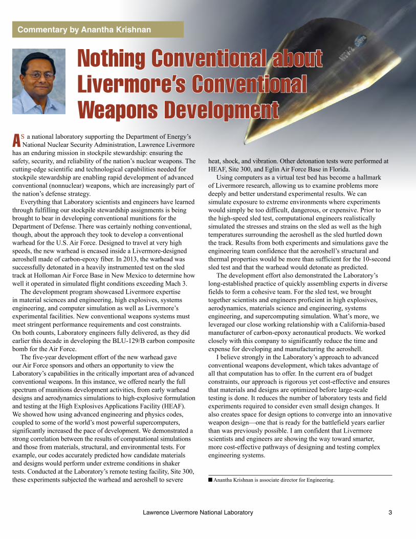
As a final verification of material robustness, a dry run was conducted at Holloman Air Force Base in July 2013. The dry run was a monorail test, in which a smaller sled ran on only one rail to save costs. The test was conducted with no warhead but with three Livermore–AASC representative carbon-epoxy panels mounted on the top and sides of the sled. The monorail test measured
An arena test at the Laboratory’s
Site 300 used an aeroshell
fashioned from commercial carbon
composite panels. This experiment
validated warhead performance
prior to the sled test.
8 Lawrence Livermore National Laboratory
S&TR December 2014Supersonic Sled Test
Carbon-epoxy panels
A monorail dry-run test at Holloman Air Force
Base in July 2013 had no payload and used three
representative carbon-epoxy panels mounted on the
top and sides of the sled. (Rendering by Kwei-Yu Chu)
the carbon-epoxy composite ablation resulting from aerodynamic and thermal effects at high speeds. It also evaluated the performance of the knifeblades in a realistic aerodynamic environment to ensure that they did not flutter or deform, and it examined the interaction between the knifeblades and the screenbox.
“We wanted to see how much ablation of the carbon epoxy material occurred at speeds even greater than what we anticipated for the full-scale sled test,” says Hare. “The dry run was an overtest because it accelerated to a higher velocity and longer duration than the actual sled test.”
The dry run, which lasted more than 60 seconds, achieved speeds in excess
9Lawrence Livermore National Laboratory
S&TR December 2014

Although the track measures 16 kilometers long, the sled test required only the last 4.8 kilometers for the 10-second run. The sled train consisted of three individual sleds—all pushed into contact with each other at the launch point. At the front, the nonpropulsive forebody sled carried the aeroshell and inside that, the warhead. The warhead’s case was fabricated at Livermore and shipped empty to the High Explosive Research and Development facilities at Eglin Air Force Base, where it was loaded with high explosive. It was then transported to Holloman Air Force Base for integration with the aeroshell.
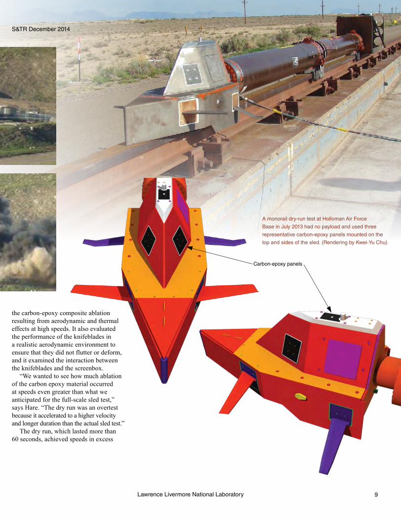
Two pusher stages propelled the forebody sled, which held the test object (the aeroshell, warhead, and detonation system) and consisted of two strut arms and bulkhead. In the first stage, four Nike rocket motors fired manually at the launch point provided the initial thrust for the entire train. The second-stage pusher sled was loaded with two Super Terrier rocket motors that were fired by screenboxes. The forebody sled knifeblades successfully contacted the track-side screenboxes, sending a signal to
of Mach 3.9. The ablation effects were thus harsher than those the sled test event would likely produce. However, all three panels exhibited minimal ablation, as anticipated. The knifeblade and screenbox functioned flawlessly. With 100 percent data return, the engineering team, together with Holloman Air Force Base personnel, began to prepare for the dual-rail sled test.
A Sled Propelled by RocketsRocket sleds have been used for
decades to simulate a flight environment for missiles, ejection seats, aircraft shapes, and even the effects of high speeds on humans. In a rocket sled test, a platform (sled) slides along two rails on steel pads called slippers that curve around the rails to prevent the sled from flying off the track. “A sled test is really an overtest of flight conditions, but it is critical to see how a weapon performs at speed,” says Hare. “The system goes through a highly dynamic environment. Components want to break apart going down the track. It’s vastly cheaper than a flight test over water, which requires clearing vessels from a corridor in the ocean.” King adds that a sled test allows researchers to observe much more than they can see in a test flight. “We can watch the system being launched and traveling down the rails,” he says.
The Holloman High Speed Test Track is similar in appearance to a railroad track.
the detonation system. This signal caused the warhead to detonate at the intended location near the end of the rails and impact various targets.
Diagnostics, some of which were designed by Livermore engineers, were deployed at the end of track and aboard the sled train. Ten channels of FM (frequency modulation) data were telemetered from the sled and collected by ground stations. Test data included acceleration, temperature, and structural loads. Doppler radar and breakwire position data measured the sled velocity. Photographic images were recorded by 44 fixed cameras and 3 tracking cameras that followed the train from start to warhead detonation.
“The sled test was an unequivocal success,” says Hare. All test objectives were met, all systems performed as planned, all diagnostics and targets captured data as designed, and the data were consistent with predictive simulations. The forebody sled achieved a maximum speed of greater than Mach 3. The Livermore-designed carbon-epoxy aeroshell survived the shock, vibration, and heat until detonation.
Rocket sleds have been used for decades to
simulate a flight environment for missiles, ejection
seats, aircraft shapes, and the effects of high
speeds on humans. (Courtesy of Holloman Air
Force Base.)
S&TR December 2014Supersonic Sled Test
10 Lawrence Livermore National Laboratory
likely behavior of materials and designs under extreme conditions. In addition, says Hare, the data gained from the sled test will be applicable to future warhead configurations.
The successful sled test and warhead development effort have been particularly satisfying to engineer Bob Addis, who was the project’s principal investigator from 2005 to 2013, when he became a deputy program director for Defense in the Laboratory’s Strategic Development Office. Addis says the effort demonstrated a Livermore core capability: advanced simulation expertise coupled to powerful computers. “We showed an extremely strong correlation between the results of our physics and engineering codes and results from our arena, structural, environmental, and sled tests,” he explains. “This is groundbreaking work, and I believe it reflects the future approach to designing new conventional weapon systems.”
Addis also notes that the team effort strengthened existing partnerships between the Laboratory’s weapons engineers and the Air Force. From sled tests to design and development efforts, Livermore engineers are shaking up weapons research and helping lead the way to new capabilities.
—Arnie Heller
Key Words: aeroshell, carbon epoxy, focused lethality munition, knifeblades, Nike rocket, NIKE3D code, supersonic sled test.
that the weapon was rugged enough for flight and for being transported.”
A Departure from the NormAccording to Hare, the sled test
“showcased what Livermore has to offer in designing and performing the system engineering of new types of aerospace systems.” He notes that legacy development processes often involved hundreds of tests, many of them repeated to assess small design changes. These repeated cycles of prototype testing can be time-consuming and expensive.
“We can now do a handful of small-scale tests, then an arena test, crunch the data, perform detailed simulations, and tell with confidence how a weapon will perform,” says Hare. “We save money and deliver the weapon more quickly. And we gain greater technical understanding than were obtained from traditional programs.”
He adds that Livermore engineers involved in designing advanced weapons systems for the Air Force continue to leverage expertise gained from using high-performance computers to determine
Livermore engineer Susan Hurd called the test a significant technology advancement. “The successful execution of this high-speed sled test of a warhead was a necessary step in the progression to an operational capability,” she says. “Now that we’ve demonstrated that the warhead functions in a flight-representative environment, we’re one important step closer to that goal.” Hurd adds that although high-performance computer modeling and simulation had been performed as well as small-scale and static tests, “in order to assess its performance in flight conditions, you have to do the dynamic test—you have to do the sled test.”
King notes that the test object behaved as the models predicted. “Our failure models, which were pivotal to the successful sled test, are overly conservative,” he says. “As a result, the sled test was a little overdesigned.”
“The sled test was the pinnacle for the program,” says Hamilton. “We started with small-scale tests that proved the materials. Then we went to full scale with static, arena, and shaker tests to demonstrate to ourselves
The forebody sled was propelled by two pusher
stages. (top) In the first stage, four Nike rocket
motors provided the initial thrust. (bottom) The
second stage was loaded with two Super Terrier
rocket motors.
S&TR December 2014 Supersonic Sled Test
11Lawrence Livermore National Laboratory

S&TR December 2014 Research Highlights
Working Smarter for a Sustainable FutureFOR many years, Lawrence Livermore employees have worked
to reduce their energy and water use, both in offices and in research labs. Long-standing efforts to do more with less have been spurred by a series of Department of Energy (DOE) guidelines and President Barack Obama’s 2009 Executive Order 13514. Under this order, federal agencies must reduce their fossil-fuel consumption, energy intensity (the energy consumed per square foot of office space), and emissions while acquiring a greater percentage of the total energy they consume from renewable sources. In addition, by fiscal year (FY) 2020, agencies must cut water consumption 26 percent below their FY 2007 levels.
The severe drought in California makes the need for action more urgent, prompting Livermore to search for innovations that will reduce its environmental footprint. “The Laboratory has been working hard to become a model sustainable enterprise,” says Michael Cowen, Livermore’s sustainability manager in the Operations and Business Principal Directorate. A sustainability campaign launched in 2008 accelerated efforts to reduce energy consumption, fossil-fuel use, and emissions from greenhouse gases and other pollutants and to adopt clean energy technologies. The campaign has also led to sitewide solutions that conserve water, reduce waste, and increase recycling.
12 Lawrence Livermore National Laboratory
Photograph by Lee Baker

A critical focus area for both water and energy conservation is the high-performance computing (HPC) facilities that house the Laboratory’s supercomputers. Although the energy efficiency of HPC processors continues to improve, the number of processors used in a system is also growing to increase computational speed. As a result, the machines consume ever-greater amounts of electricity and generate large amounts of heat that must be removed using air- and water-based cooling systems.
Reducing Greenhouse GasesOne notable accomplishment for the sustainability campaign is
surpassing the federal goal for FY 2020 of reducing greenhouse-gas emissions by 28 percent of the FY 2008 baseline. The campaign team met this target primarily by implementing a plan to manage and capture gaseous sulfur hexafluoride (SF6), which dramatically reduced SF6 emissions.
Sulfur hexafluoride is used in extremely small quantities at Livermore for research activities involving accelerators, electrical power distribution equipment, electron microscopes, flash x-ray units, and some etching technologies. Even in small quantities, the compound receives intense scrutiny because 1 kilogram of SF6 has the greenhouse-gas effect of 23,900 kilograms of carbon dioxide. The SF6 Management and Capture Plan modified operations involving the compound to improve equipment leak detection, increase preventive maintenance, and ensure that gas-transfer and emissions-capture operations are more efficient.
Assault on Power WasteElectricity consumption is another focus area for the
sustainability campaign. Cowen says that both office buildings and research facilities offer opportunities for reducing electricity use, which at Lawrence Livermore averages 50 megawatts per year. To ensure that facilities operate at maximum efficiency, workers are modernizing heating, ventilation, and air-conditioning (HVAC) systems. In addition, they are installing motion controllers that turn off lights in unoccupied offices and conference rooms, boilers that have improved energy efficiency ratings, and streetlights that use light-emitting diodes.
President Obama’s executive order also requires federal agencies to use renewable energy sources to supply 20 percent of electrical power. Livermore has already achieved 17 percent, largely because it purchases energy generated by the hydroelectric plants operated by the Western Area Power Administration.
To help meet the 20-percent mandate, Laboratory managers are working with the DOE Livermore Field Office to prepare for a 3-megawatt solar photovoltaic system, which will be located on a 10-acre section of the main site’s northwest buffer zone. Because the plant will be built on site, Livermore will receive
a double renewable energy credit. DOE is soliciting proposals from developers to design, finance, build, operate, and maintain a ground-mounted solar power installation for at least the next 20 years. Lawrence Berkeley National Laboratory is also a partner on this project and has agreed to purchase 20 percent of the electricity generated by the solar-powered system.
Another sitewide effort is consolidating the computer servers that operate business-oriented applications. Cowen notes that racks of these heat-generating servers are housed in buildings throughout the site, but the HVAC systems in those facilities were designed for office environments. “We’ve been asking buildings to support operations they weren’t designed to handle,” he says. By consolidating the business systems, the sustainability team has reduced the number of buildings with servers from 60 to fewer than 25. The ultimate goal is to establish an enterprise data center with seven specialized facilities for business operations.
Coping with Severe DroughtCalifornia’s severe drought has prompted vigorous water
conservation efforts statewide as well as mandatory rationing in hard-hit areas. In light of this emergency, water conservation has become a critical task at Lawrence Livermore. About 45 percent of Livermore’s water consumption is directed to five cooling towers that provide air-conditioning for the HPC systems, 30 percent is for domestic use (such as sinks and toilets), and 25 percent goes toward landscape irrigation.
Livermore is planting water-wise shrubs to reduce the amount of water
required for landscaping. (Photograph by Paul Hara.)
S&TR December 2014 Sustainability Efforts
13Lawrence Livermore National Laboratory

the amount of potable water the Laboratory purchases from the Hetch Hetchy Reservoir operated by the San Francisco Public Utilities Commission.
According to Jesse Yow, head of Livermore’s Environmental Restoration Department, the Laboratory treats groundwater at its main site to reduce contaminants to levels acceptable for water discharge into the storm sewer system, although the treated water is not pure enough for drinking or irrigation. Most of the contaminants—called volatile organic compounds—are legacy waste from the 1940s, when the square-mile site served as a U.S. Naval air station. Groundwater from about 90 wells across the Laboratory is pumped through 25 treatment facilities. Water leaving one of the treatment facilities is sent through the reverse-osmosis pilot plant, which then pipes purified water to a nearby cooling tower.
Yow notes that under the restoration program, treated groundwater is provided to the pilot plant when it is available. In addition to construction costs, the plant incurs expenses for electricity, maintenance, and sewer fees. Nevertheless, Cowen says reverse osmosis is a cost-effective solution. “The plant is on track to save 7 million gallons of potable water that would otherwise be purchased and earmarked for the cooling tower. We’re very encouraged by these results,” adding that reverse-osmosis plants are being considered for the other cooling towers.
Computing Offers Energy SavingsOperating HPC systems also requires a large power supply. In
fact, supercomputers, which must run around the clock to support research efforts, consume half of the electricity purchased by the Laboratory. Livermore managers developed a master HPC
Livermore engineer Ruben Ocampo (left) and Michael
Cowen, the Laboratory’s sustainability manager, tour a
pilot reverse-osmosis plant designed to prepare treated
groundwater for use in one of the Laboratory’s five
cooling towers. The plant is on track to save 7 million
gallons of potable water from the Hetch Hetchy reservoir
in California. (Photograph by Don Johnston.)
Each year, the Laboratory uses about 62 million gallons of water to landscape 35 acres of lawn, or turf, and 60 acres of shrubs. Turf requires significantly more water to irrigate than do “water-wise” shrubs: 30 gallons per square foot for turf versus 5 to 10 gallons per square foot for shrubs. As a result, the Laboratory is increasing its use of water-wise plants. Jacquelyn Westfall, who leads Livermore’s infrastructure maintenance services, notes that the Sustainable Landscape Concept Plan developed in 2011 is helping meet a 2014 goal of reducing water consumption by 13 million gallons. Most of the savings are from eliminating irrigation on 7 acres of turf and reducing the watering schedule sitewide.
According to lead landscaper Michael Bohannon, turf watering encourages trees to grow shallow roots. In areas where lawns are no longer irrigated, workers have installed a deep drip system around trees. “We want to protect our huge investment in the thousands of trees planted on site,” says Cowen. In addition, the landscape team installed 14 satellite irrigation controllers to ensure effective watering with minimal runoff. Other measures include reclaiming rainwater from several buildings and blending treated groundwater with potable water for irrigation.
Reverse Osmosis a SuccessAn innovative water-conservation effort is a reverse-osmosis
pilot plant that filters treated groundwater so it is clean enough for use in a cooling tower. Cooling towers require continuous supplies of water to replenish what is lost to evaporation and to reduce the concentrations of dissolved minerals circulating through the system. High mineral concentrations can foul heat exchangers and interfere with heat transfer. Using treated groundwater reduces
S&TR December 2014Sustainability Efforts
14

sustainability plan, referred to as Turning Megawatts to Petaflops, to ensure that current and future energy requirements can be met while limiting the impact on environmental resources.
The Laboratory’s largest HPC facility is home to some of the world’s most powerful systems, including Sequoia, Vulcan, and Zin. The facility provides more than 48,000 square feet of floor space for systems and peripherals that consume 30 megawatts of power, not counting the energy required to run the facility’s machine-cooling system.
The biggest electricity user by far is Sequoia. This system has more than 1.5 million processor units, or cores, compressed into 96 racks, each the size of a large refrigerator, providing 1.6 petabytes (1015 bytes) of memory. (See S&TR, July/August 2013, pp. 4–13.) Sequoia is equipped with energy-efficient features such as a 480-volt electrical distribution system for reducing energy losses. In 2012, the Green500 organization named the IBM system the “world’s most efficient supercomputer.”
Much of Sequoia’s energy consumption is tied to keeping it cool, with both air (9 percent) and water (91 percent). Facility engineers discovered that raising the ambient temperature from 52°F to 70°F did not degrade performance or damage components, saving more than $1 million annually in electricity. Sequoia’s water-cooling system is more than twice as energy efficient as air-cooling. A labyrinth of pipes under the floor of the computer room distributes chilled water in a vast network of polypropylene channels.
“We need to make the best use of the water resources we have on site,” says Anna Maria Bailey, who manages Livermore’s computing facilities. To that end, Livermore is looking to construct another reverse-osmosis plant to feed the cooling tower that serves
Cooling towers, which feed water
to the air-conditioning systems for
the Laboratory’s high-performance
computing facilities, account for
about 45 percent of the total water
consumption at Livermore’s main
site. (Photograph by Lee Baker.)
the HPC facility because this tower accounts for about 20 percent of the Laboratory’s total water use.
Supercomputers must become more efficient, says Bailey, because their increasing needs for water and energy cannot be met by existing utilities. The exascale computers of the future will be nearly 1,000 times more powerful than some existing supercomputers and demand innovative designs from vendors. According to Bailey, one approach for those new machines may be to submerge them in an inert liquid, which would significantly reduce the cooling challenge.
In the meantime, the Laboratory is building a new HPC facility to accommodate next-generation supercomputers. When completed in 2015, it will be a showcase for lessons learned from past modernization projects at existing HPC facilities. “We’re taking a modular approach with an emphasis on sustainability,” says Bailey. The building will have expandable construction features that can be scaled as computational technology evolves.
Cowen notes that the growing sustainability efforts are consistent with the Laboratory’s prodigious research output. Generating renewable electricity on site, decreasing water and electricity usage, and reducing greenhouse-gas emissions all lead to greater productivity and are part of being a good neighbor.
—Arnie Heller
Key Words: drought, energy conservation, high-performance computing (HPC), reverse osmosis, Sequoia supercomputer, sulfur hexafluoride (SF6), sustainability, water conservation.
For further information contact Michael Cowen (925) 422-6337
© ivan kmit - Fotolia.com
Sustainability Efforts
15Lawrence Livermore National Laboratory

Research Highlights S&TR December 2014
16 Lawrence Livermore National Laboratory
© D
anie
l Sch
wen
- c
omm
ons.
wik
imed
ia.o
rg
16
Crystals Go under the Microscope
Lawrence Livermore National Laboratory
CRYSTALS have long been admired for their symmetry and regularity. Scientific inquiry into their nature began in the
early 17th century, when German astronomer and mathematician Johannes Kepler hypothesized that the symmetric shape of snowflakes was due to their underlying structure. This observation launched the study of crystallography, a field that was substantially advanced at the start of the 20th century by the pioneering research of Max von Laue and William and Lawrence Bragg. Von Laue found that x rays traveling through a crystal interact with its crystallographic planes and are scattered in directions specific to a crystal’s type. This discovery led to him winning the 1914 Nobel Prize in Physics. The Braggs earned the prize the following year
for showing that information on the direction and intensity of diffracted beams can be used to create a three-
dimensional (3D) image of a crystal’s structure. To celebrate the achievements of von Laue, the
Braggs, and Kepler, the United Nations named 2014 the International Year
of Crystallography.
Research Highlights S&TR December 2014

S&TR December 2014 Crystallography
17Lawrence Livermore National Laboratory
Modern crystallographic research, performed using diffraction and various kinds of microscopy, underpins many realms of science. In areas as diverse as weapons, lasers, energy, and biotechnology, Livermore scientists use the micrometer- and nanometer-scale structural knowledge obtained through crystallography to better understand a material’s macroscale properties and predict the performance of advanced metals, alloys, and ceramics. Their investigations of polycrystalline materials typically focus on grain boundaries, the interfaces between individual crystals. The 3D arrangement of the crystals, or grains, and how those grains interact with one another affect a material’s mechanical, thermal, chemical, and electrical properties. For instance, grain boundaries influence how a metal behaves when it is squeezed or stretched and how likely it is to crack or corrode.
Crystal orientation mapping is a key method for characterizing grains and grain boundaries. Lawrence Livermore is one of the few institutions worldwide to maintain expertise in the three principal mapping techniques: scanning electron microscopy (SEM), transmission electron microscopy (TEM), and high-energy diffraction microscopy (HEDM). These methods, used singly or in combination, provide structural information at a range of scales, which is valuable in developing materials for various scientific and engineering applications.
A Characterization WorkhorseElectron backscatter diffraction (EBSD) is an SEM-based
technique that images a material’s microstructure with a resolution of 20 to 50 nanometers. EBSD experiments on crystalline samples with features from 100 nanometers to 1 millimeter in diameter reveal the size and shape of individual grains, boundary
characteristics, orientation, distribution of orientations (often referred to as texture), and phase identity.
In EBSD experiments, an SEM’s stationary electron beam strikes a tilted crystalline sample, and the diffracted electrons form a pattern of intersecting bands on a fluorescent screen. The pattern is captured by a digital camera, which passes the data to specialized computer software for analysis. Given initial input about the types and potential phases of crystals under study, the software compares the generated image with mathematically predicted diffraction patterns of a model structure, refining the model’s predictions until they closely match the actual pattern. Scanning multiple points on the sample with the electron beam enables the system to reconstruct an orientation map of the sample’s surface microstructure. Scientists can then apply various statistical tools to measure average misorientation, grain size, texture, and other features.
Livermore researchers have been using SEM-based EBSD for nearly two decades and thus have considerable expertise with this technique, even compiling two editions of an authoritative EBSD textbook. In fact, the Laboratory acquired one of the first commercial systems and helped develop and test data-analysis algorithms that were later incorporated into the standard EBSD software. Livermore materials scientists also worked to improve the technique’s efficiency and ease of use. For example, the pattern indexing process, once a tedious manual task, is now automated and takes less than a few milliseconds with modern computers.
Materials scientist Mukul Kumar in Livermore’s Engineering Directorate performs EBSD characterization experiments for additive manufacturing research. “This technique is part of the material development cycle for our laser melting additive manufacturing work
Livermore scientists can examine a material’s microstructure at multiple scales using three crystal orientation mapping techniques: (left) scanning electron
microscopy (SEM), (middle) transmission electron microscopy (TEM), and (right) high-energy diffraction microscopy (HEDM). The HEDM microstructures are
about 1 millimeter in diameter.
0.5 micrometers 280 micrometers

S&TR December 2014Crystallography
18 Lawrence Livermore National Laboratory
allowing researchers to analyze grains at a level of detail, accuracy, and efficiency not possible with the manual approach.
For TEM mapping, samples are made extremely thin—preferably, a single grain thick—so that electrons can pass through them. The volume of material sampled is too small for collecting statistical information about crystal structure, but it does provide a more detailed view than EBSD does of specific boundaries or sample regions. Orientation mapping with TEM also helps researchers understand how a material’s microstructure evolves during processes such as annealing.
Materials scientist Joe McKeown uses the TEM mapping technique to illuminate crystal growth in metals and alloys during nonequilibrium solidification processes. (See S&TR, September 2013, pp. 4–11.) In experiments with an aluminum–copper alloy, he compared orientation maps created before and after solidification and noted some unexpected behavior. “With that alloy, we might expect the grains to grow with a specific orientation,” says McKeown. “Instead, mapping showed that the growth orientations were almost completely random. Our finding indicates the material cooled very quickly, so growth orientation was not a significant factor.”
New Dimensions “What typically determines the lifetime of a component is
its failure through crack formation or other processes that are dominated by rare events—say, 1 in 10,000,” says computational engineer Shiu Fai (Frankie) Li. “The only way to study such events is to increase the sample size.” The newest of the three mapping techniques, HEDM, offers that capability. With HEDM, high-energy x rays penetrate millimeters or centimeters below a material’s surface to map its internal microstructure in 3D. The trade-off for larger-scale mapping is reduced spatial resolution, limited to 1 micrometer.
“HEDM lets us resolve as many as 250,000 individual crystals,” says materials scientist Joel Bernier. “It’s like doing 250,000 single-crystal experiments concurrently and getting information on the interactions between the crystals. Lots of interesting interactions are occurring at this scale.” In collaboration with the Air Force Research Laboratory, Bernier is applying HEDM to study the formation and evolution of microcracks and voids in titanium under the stress of a constant load. Results will be used to design more durable jet engine turbines.
During an HEDM experiment, 0.025- to 0.01-nanometer x rays are focused into a micrometer-high beam, which illuminates a small section of a rotating cylindrical sample only 1 millimeter in diameter. A charge-coupled device detector captures the patterns formed by the x-ray–crystal interactions and sends them to a supercomputer for data analysis. As in the early years of SEM and TEM orientation mapping, reconstructing a crystal’s microstructure with HEDM is extremely challenging. Li and
at the Laboratory,” notes Kumar. “It allows us to quickly examine large amounts of data to determine grain size and orientation.”
Taking a Closer LookA newer technique called TEM-based orientation mapping
examines crystal orientation and texture at a finer spatial scale than SEM. This technique uses precession electron diffraction to produce higher-quality maps than EBSD can generate and with fewer artifacts. When TEM transmits a beam of electrons through an ultrathin material sample, the electrons interact with a crystal’s atoms and form a diffraction pattern. The pattern is magnified and focused onto a fluorescent screen, where it is captured by a camera and passed to software for indexing and analysis. Livermore scientists’ experience with fine-tuning EBSD analysis has aided efforts to automate the TEM mapping process and enhance the associated software, most recently by improving resolution to 2 nanometers. A single scan with the automated TEM process can probe and map hundreds of thousands of points on a sample,
Livermore scientists used SEM-based electron backscatter diffraction to
study crack propagation. This technique reveals how cracks travel through
different microstructures, allowing researchers to predict when and where
fractures will form and what paths they will follow—information that helps
pinpoint where a component is most likely to fail. In the bottom image, colors
indicate grain orientation.
175 micrometers
175 micrometers

S&TR December 2014 Crystallography
19Lawrence Livermore National Laboratory
induced grain growth. The network of grain boundaries, particularly the connectivity of twin boundaries within a material, governs how likely a metal is to coarsen and crack. Says Kumar, “When it comes to grain coarsening, we’ve shown that the spatial distributions of these special boundaries matter, even in pure metals. This is a scientifically interesting result.”
At Livermore, scientists are making steady advances in their work to understand, anticipate, and control material properties at a range of scales. The research methods they have developed for mapping crystal orientations and boundary regions can be applied to pure metals such as copper and tantalum, which serve as proxies for many Laboratory efforts, as well as to more commercial materials such as stainless steel and nickel-based alloys, which are used in nuclear reactors and other applications. “The Laboratory has played a significant role in extracting information on microstructure by looking at networks spanning hundreds or thousands of grains,” observes Kumar. “We’re pushing the limits of technologies that in some cases didn’t exist even five years ago.”
—Rose Hansen
Key Words: additive manufacturing, crystallography, electron backscatter diffraction (EBSD), high-energy diffraction microscopy (HEDM), precession electron diffraction, scanning electron microscopy (SEM), transmission electron microscopy (TEM).
For further information contact Mukul Kumar (925) 422-0600
postdoctoral researcher Jonathan Lind are developing and refining advanced computational techniques and related software components for collecting and analyzing the diffraction patterns. Both researchers were students of Robert Suter at Carnegie Mellon University, who codeveloped the HEDM technique.
“The data output from an HEDM experiment is immense,” says Li. “The increasing computational power available allows us to use technologies that 20 years ago could not handle all of that information. As it is, we’re pushing the limits of the resources we have for collecting statistics and reconstructing objects in 3D.”
Three-dimensional imaging with SEM and TEM is time consuming and requires removing successive layers of a sample to record and analyze its microstructure, which destroys the sample. HEDM also acquires 3D measurements layer by layer, but the process is nondestructive. As a result, the technique facilitates in situ study of material dynamics—how the microstructure responds to mechanical or thermal stimuli—as well as experimental modeling. The HEDM characterization technique is growing in popularity. At present, the Advanced Photon Source at Argonne National Laboratory is the only U.S. site performing HEDM experiments, but Livermore materials scientists are helping to establish a second facility at Cornell University’s High Energy Synchrotron Source.
Even Better TogetherIndividually, the three orientation mapping technologies
are quite effective. Used in concert, they offer scientists an unprecedented understanding of material microstructure, from the nanometer to the micrometer length scale. For example, in an effort funded by the Department of Energy’s Office of Basic Energy Sciences, Livermore researchers are applying the techniques to study at multiple scales how radiation-induced defects interact with internal interfaces, which can lead to heat-induced grain growth (thermal coarsening) and fracturing. This work could help scientists design new materials for next-generation nuclear reactors.
By combining the techniques, the researchers have tracked and compared grain growth and grain-boundary evolution in stainless-steel and copper samples that have different concentrations of a special boundary called a twin boundary. A twin boundary, like a grain boundary, has different crystal orientations on its two sides, but the orientations are not random; rather, they mirror one another. (See S&TR, January/February 2014, pp. 12–15.) A high concentration of twin boundaries in a metal increases that metal’s strength. The Livermore team’s research showed, however, that these boundaries alone will not prevent thermally or mechanically
Crystal orientation mapping with HEDM reveals subtle changes in the
curvature of a material’s surface and the shape of each grain as it is
squeezed, stretched, twisted, or heated. The maps shown here capture
a material’s microstructure at three stages of an annealing experiment.

Research Highlights
20 Lawrence Livermore National Laboratory
THE deaths of stars are not as final as they seem. These often-violent events give rise to exotic stellar remnants that are
dispersed throughout the cosmos. Neutron stars, for example, are created when very massive stars (those with a mass between 10 and 30 times that of our Sun) exhaust their supply of nuclear fuel and die in supernovae explosions. The star generated from such a spectacular event has a radius of about 10 kilometers, mass around 1.5 times that of the Sun, and density of roughly 1017 kilograms per cubic meter (close to the density of a black hole). Neutron stars are thus some of the tiniest, densest celestial objects in the known universe, and they exhibit some of the strongest magnetic fields ever observed. As they are born, they spin rapidly, and this spinning in conjunction with their high magnetic fields produces intermittent pulses of intense radio, x-ray, and gamma-ray emissions.
NuSTAR Peers into the Neutron Star Zoo
Research Highlights
Lawrence Livermore National Laboratory
S&TR December 2014
20
More than 40 years after their discovery in the late 1960s, neutron stars continue to intrigue and astonish scientists. “Neutron stars are extreme objects,” says Livermore astrophysicist Julia Vogel, who works in the Physical and Life Sciences Directorate. “Just imagine something with the mass of our Sun squeezed into the San Francisco peninsula spinning at the speed of a household blender.” Although neutron stars were initially believed to belong to a uniform, simple class of stars, research over the last decade has revealed a “zoo” of objects with remarkably diverse properties and behaviors.
The study of neutron stars has been given a significant boost with the Nuclear Spectroscopic Telescope Array (NuSTAR), a NASA Small Explorer Mission launched in 2012. The technology behind NuSTAR has its roots in Livermore-based research and development. (See S&TR, March 2006, pp. 14–16.) With its two

21Lawrence Livermore National Laboratory
knowledge of stellar evolution, galactic population synthesis, and the study of matter under extreme conditions.”
Unpredictable BehaviorNeutron star types are characterized by the star’s rotational
period and the rate at which it slows. By measuring these two properties, scientists can derive the strength of a star’s magnetic field and its age. Most neutron stars were discovered by detecting the radio-frequency signals emitted when kinetic energy is converted into electromagnetic energy (via the stars’ magnetic braking). Because a radio pulsar’s spin axis does not align with its magnetic field, its emissions seem to pulse when viewed from Earth. Radio pulsars are thousands to hundreds of millions of years old, and they exhibit a very large range of magnetic field strengths.
Magnetars, on the other hand, are the youngest neutron stars and have the most powerful magnetic fields among pulsars, measuring up to a quadrillion (1015) gauss. Magnetars also produce emission observable as periodic pulsation, but they spin more slowly than typical radio pulsars, completing a revolution in 1 to 10 seconds instead of 1 millisecond or less. Interestingly, kinetic energy in spinning magnetars is insufficient for explaining the intensity of their energetic x-ray pulses. “Way more energy comes from magnetars than their kinetic energy alone would allow,” says Pivovaroff, whose expertise is in x-ray optics and astronomy. In addition, the temperamental stars are prone to irregular outbursts of electromagnetic radiation that can affect their rotational period and visibility. “We know their location precisely,” adds Pivovaroff. “Yet sometimes magnetars cannot be detected, and at other times, they are really bright, with intensity increasing by a factor of 10 to several hundreds.”
The current theory is that magnetars produce x-ray and gamma radiation through the decay of their inner magnetic fields, but the
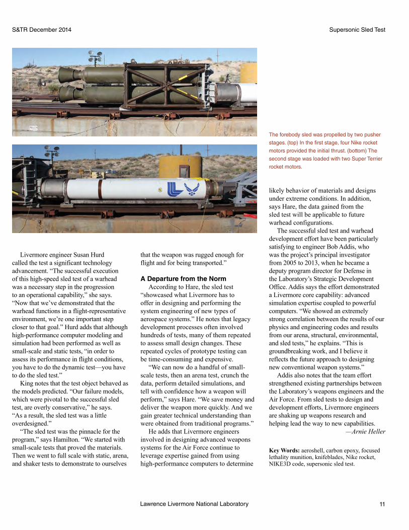
NASA’s Nuclear Spectroscopic Telescope Array (NuSTAR, above) is the first
focusing observatory deployed in orbit for measuring hard x-ray energies
between 3 and 80 kiloelectronvolts (keV). NuSTAR contains two focusing
telescopes and an array of detectors and is more sensitive than previous
technologies for this energy range. The composite background image (left)
shows low-energy (soft) x-ray data collected by NASA’s Chandra X-Ray
Observatory, infrared data captured by the Spitzer Space Telescope, and
pulsar PSR J1640-4631 (blue), which was discovered by NuSTAR and lies
in the inner Milky Way galaxy. (Courtesy of NASA, Jet Propulsion Laboratory
[JPL], and California Institute of Technology [Caltech].)
S&TR December 2014 NuSTAR
x-ray telescopes and advanced semiconductor detectors, NuSTAR achieves sensitivity 100 times greater and resolution 10 times better than previous high-energy satellite observatories.
In 2013, Vogel began leading a Laboratory Directed Research and Development (LDRD) project that uses NuSTAR to study the hard x-ray emission produced by magnetars—neutron stars with extremely strong magnetic fields. Her team, which includes Laboratory scientist Michael Pivovaroff and astrophysicist Victoria Kaspi from Canada’s McGill University, are using data from NuSTAR to delve further into the energetic nature of neutron stars. NuSTAR’s ability to observe emission at higher angular and energy resolutions will help the researchers better understand how neutron stars produce x rays and whether a star’s properties are determined at birth or are influenced by its environment.
“Our goal is to develop a ‘grand unification theory’—an overarching theory of neutron star physics and the birth properties of these objects—to explain their incredible diversity,” says Vogel. “NuSTAR observations are helping us understand these ubiquitous and mysterious stellar objects, which will improve our

S&TR December 2014NuSTAR
22 Lawrence Livermore National Laboratory
underlying physics and production mechanisms for electromagnetic generation are not well understood. Previous attempts to study magnetar properties in detail were hindered by the limited imaging capabilities of the available hard x-ray observatories. The hard x-ray band is important because it is a transition region from thermal processes to nonthermal ones. NuSTAR is the first focusing hard x-ray observatory deployed in orbit for measuring energies between 3 and 80 kiloelectronvolts (keV). Its two multilayer-coated telescopes image hard x rays onto a sophisticated detector array, which is separated from the optics by a 10-meter mast. The optics, which the Livermore team helped design, build, and calibrate, are key to NuSTAR’s improved resolution.
During the first year of the LDRD study, the research team created data-analysis tools, including novel algorithms based on existing codes, to interpret the NuSTAR measurements. “Prior to conducting scientific observations, we had the instrument look at well-documented stellar objects as part of our in-orbit calibration efforts,” says Vogel. “We then compared the data to our physics-based computational models, which were designed to predict what we would see in space.”
The NuSTAR team discovered that ground calibration models could not fully explain the instrument’s in-orbit measurements. This finding was not completely unexpected because simplified models were being used to describe extremely complex phenomena. “The calibration data helped us further improve the models and better understand the discrepancies,” says Vogel. “At Livermore,
we were responsible for precision metrology, evaluation, and implementation of results into the ray trace
modeling.” Ultimately, the NuSTAR team improved the physics models
in the simulations, which reduced the discrepancies between model results
and observed data to a level comparable to that achieved for other missions.
A High-Energy RevelationIn 2014, the research team focused
on detecting and analyzing the hard x-ray spectra from several magnetars. “We took
an extensive look at one of the most studied magnetars (1E 2259+586), which prior to
NuSTAR had been only marginally detected in the hard x-ray energy range,” says Vogel.
Spectroscopic techniques determine what energies are emitted by the magnetars and how
the spectra differ for the pulsed and constant emission. “We detected hard x-ray pulsations above
20 keV for the first time and studied the magnetar’s spectrum at higher energies than were previously
Magnetars, such as the one in this artist’s rendering, are thought to be
newly formed, isolated stars that have extremely powerful magnetic fields
and emit radiation from their magnetic poles. Their irregular bursts of
energy affect their rotational period and visibility. (Courtesy of European
Southern Observatory.)
With NuSTAR, researchers can retrieve more detailed images of stellar objects by measuring
hard-x-ray emissions. The ROSAT (Röntgen Satellite) Mission, which records emissions
between 0.1 and 2.4 keV, captured the left image of supernova remnant CTB109 and
magnetar 1E 2259+586 (bright point). The white frame indicates the NuSTAR field of view.
(right) Spectroscopic data recorded by NuSTAR in the 3- to 80-keV range provide more
details on the magnetar and its environment.
Increasing intensity
5 arcminutes
2 arcminutes
S&TR December 2014 NuSTAR
23Lawrence Livermore National Laboratory
capabilities will be needed for future astrophysics research.” As this research continues, Vogel eagerly anticipates the discoveries to be made during the next year. Only time will tell whether the “animals” in the neutron star zoo share a common connection or if each is a breed of its own.
—Caryn Meissner
Key Words: astronomy, astrophysics, magnetar, magnetic field, NASA Nuclear Spectroscopic Telescope Array (NuSTAR), neutron star, optics, pulsar wind nebula, radio pulsar, Small Explorer Mission.
For further information contact Julia Vogel (925) 424-4815
accessible,” she adds. “The hard x-ray data revealed that additional spectral components, which were not required for lower energy (or soft) x-ray measurements alone, were needed to describe the magnetar’s hard and soft x-ray emission together.”
The team fit the x-ray data obtained from NuSTAR to a recently developed electron–positron outflow model called the Beloborodov model, which could explain the properties and origin of the x-ray emission. “We determined spectral parameters, pulse profile, and pulsed fractions for the NuSTAR data and were able to support the theoretical model,” says Vogel. “Even though current data do not tightly constrain the model parameters, we found that the outflow is likely to originate from a ring on the magnetar rather than from its polar cap, which is surprising.” The team’s findings also support a connection between the spectral turnover and the star’s magnetic fields, consistent with previous observations of other magnetars.
Using a similar analysis approach, the team characterized a newly discovered magnetar. “We obtained the first timing information of the star, showing that its spin-down rate increased without a glitch,” says Vogel, explaining that a glitch is the sudden spin-up or spin-down that can occur when fluid inside a neutron star rotates faster than the star’s crust. “Because no glitch was observed, the increase is likely to be of magnetospheric origin.”
The researchers also analyzed spectra from pulsar wind nebulae. These objects form when charged particles are accelerated to relativistic speeds by the neutron star’s rapidly spinning, extremely strong magnetic fields, and they are shocked when constrained by the environment surrounding the star. Observing pulsar wind nebulae will help the team identify the composition of outflowing matter and the relative amount of energy stored in the outflow particle versus the magnetic fields. “Hard x-ray studies enable us to analyze systems where soft x rays are absorbed by interstellar dust,” says Vogel. “The first observations of the Geminga pulsar wind nebula were used for spectroscopy, and the rotation-powered pulsar was detected for the first time in hard x rays above 10 keV.”
Resolving Mysteries in X-Ray Astronomy“What is being achieved with NuSTAR and Julia’s team is
a culmination of more than 10 years of LDRD support,” says Pivovaroff, who worked on the NuSTAR design and helped build the instrument. “Livermore had the long-term commitment and vision to invest in early technology development. Now that it has transitioned into a satellite instrument, we are using the technology to further our understanding of fundamental science.”
As Vogel and her team continue to advance knowledge of neutron star physics, they look forward to resolving other mysteries in x-ray astronomy. “We can leverage the experience gained from NuSTAR for developing the next generation of x-ray telescopes,” she says. “By being involved in building NuSTAR and its science mission, we can gain a better understanding of what
This composite image of the nebula around pulsar PSR B1509-58
illustrates pulsar wind nebulae. Data were recorded by the Chandra X-Ray
Observatory at 0.5 to 2 keV (red) and 2 to 4 keV (green) and by NuSTAR
at 7 to 25 keV (blue). NuSTAR’s hard x-ray view reveals the central pulsar.
Similar images were obtained for Geminga. (Courtesy of NASA, JPL,
Caltech, and McGill University.)

S&TR December 2014
24 Lawrence Livermore National Laboratory
Patents and AwardsIn this section, we list recent patents issued to and awards received by Laboratory employees. Our goal is to showcase the distinguished scientific and technical achievements of our employees as well as to indicate the scale and scope of the work done at the Laboratory.
Patents
structure. The system detects change by comparing the attributes and topology of new objects found on the most recent scan to the constellation database of previously detected objects.
Combined Raman and IR Fiber-Based Sensor for Gas DetectionJerry C. Carter, James W. Chan, James E. Trebes, Stanley M. Angel, Boris Mizaikoff U.S. Patent 8,759,767 B2June 24, 2014This double-pass fiber-optic spectroscopic gas sensor delivers Raman excitation light and infrared light to a hollow structure, such as a hollow fiber waveguide, containing a gas sample of interest. A retroreflector placed at the end of the structure sends light back through the waveguide where the light is detected at the same end as the light source. This double-pass retroreflector design increases the interaction path length of the light and the gas sample and reduces the form factor of the hollow structure.
Centrifugally Decoupling Touchdown BearingsRichard F. PostU.S. Patent 8,760,021 B2June 24, 2014Centrifugally decoupling mechanical bearing systems provide thin tensioned metallic ribbons contained in a support structure that rotates around a stationary shaft centered at low speeds by the action of the metal ribbons. Tension springs are connected to the ribbons on one end and to the support structure on the other end. The ribbons pass through slots in the inner ring of the support structure. The spring preloading thus ensures contact (or near contact) between the ribbons and the shaft at rotation speeds below the transition speed. Above this speed, however, the centrifugal force on the ribbons produces a tensile force on them that exceeds the spring tensile force so that the ribbons curve outward, effectively decoupling them from mechanical contact with the shaft. They still remain in position to act as a touchdown bearing in case of abnormally high transverse accelerations.
Methods for Threshold Determination in Multiplexed AssaysLance F. Bentley Tammero, John M. Dzenitis, Benjamin J. HindsonU.S. Patent 8,762,068 B2June 24, 2014These methods for determining threshold values of signatures in an assay enable target detection. The methods determine a probability density function of negative samples and a corresponding false-positive rate curve. A false-positive criterion is established, and a threshold for that signature is determined as a point at which the false-positive rate curve intersects the false-positive criterion. Also described are a quantitative method for analyzing and interpreting the assay results and a method for determining a desired limit of detection for a signature in an assay.
Microcantilever-Based Gas Sensor Employing Two Simultaneous Physical Sensing ModesAlbert Loui, Donald J. Sirbuly, Selim Elhadj, Scott K. McCall, Bradley R. Hart, Timothy V. RattoU.S. Patent 8,762,075 B2June 24, 2014A system designed for detecting and identifying gases includes a piezoresistive microcantilever transducer, wherein dissipation of heat from
Cryogenically Cooled Detector Pin MountWilliam E. Hunt, Jr., Michael P. ChrispU.S. Patent 8,740,168 B2June 3, 2014With this focal plane assembly, a molybdenum baseplate can be mounted to another plate made from aluminum. The molybdenum pin is an interference fit (press fit) in the aluminum baseplate. An annular cutout area in the baseplate forms two annular flexures.
Resistive Foil Edge Grading for Accelerator and Other High Voltage StructuresGeorge J. Caporaso, Stephen E. Sampayan, David M. SandersU.S. Patent 8,749,949 B2June 10, 2014When voltage is placed across a structure or device with a pair of electrical conductors separated by an insulator, resistive layers form around the conductors to force the electric potential within the insulator to distribute more uniformly and thus decrease or eliminate electric field enhancement at the conductor edges. The properties of resistive layers allow the voltage on the electrode to diffuse outward, reducing the field stress at the conductor edge. Tapered resistivity is preferred for this layer, with lower resistivity adjacent to the conductor and higher resistivity away from it. Generally, a resistive path across the insulator is provided, preferably by a region in the bulk of the insulator over which the resistive layer extends.
Two-Phase Mixed Media Dielectric with Macro Dielectric Beads for Enhancing Resistivity and Breakdown StrengthSteven Falabella, Glenn A. Meyer, Vincent Tang, Gary GuethleinU.S. Patent 8,749,951 B2June 10, 2014This two-phase mixed-media insulator has a dielectric fluid filling the interstices between macro-sized dielectric beads packed into a confined volume. The packed dielectric beads inhibit electro-hydrodynamically driven current flows of the dielectric liquid and thereby increase the resistivity and breakdown strength of the two-phase insulator over the dielectric liquid alone. In addition, an electrical apparatus incorporates the two-phase mixed-media insulator to insulate between electrical components characterized by different electrical potentials. A method of electrically insulating between electrical components of different electrical potentials fills a confined volume between the electrical components with the two-phase dielectric composite. The macro dielectric beads are packed in the confined volume, and the interstices formed between the macro dielectric beads are filled with the dielectric liquid.
Determining Root Correspondence between Previously and Newly Detected Objects David W. Paglieroni, N. Reginald BeerU.S. Patent 8,754,802 B2June 17, 2014This system applies attribute- and topology-based change detection to networks of objects that were detected on previous scans of a structure, roadway, or area of interest. The attributes capture properties or characteristics of the objects, such as location, time of detection, size, elongation, and orientation. The topology of the network of previously detected objects is maintained in a constellation database that stores the object’s attributes and implicitly captures the network’s geometric

25Lawrence Livermore National Laboratory
S&TR December 2014 Patents and Awards
the piezoresistive microcantilever into one or more gases is measured by changes in an electrical resistance. Shifts are measured in resonant frequency of the vibrating microcantilever due to viscous damping by one or more gases. A subsystem then correlates the measured changes in resistance and the shifts in resonant frequency to identify one or more gases. A method for detecting and identifying one or more gases includes determining both the dissipation of heat from a microcantilever into one or more gases and the shifts in resonant frequency of the microcantilever due to viscous damping by one or more gases. Other systems, methods, and computer program products are also described.
Electrochemical Formation of Hydroxide for Enhancing Carbon Dioxide and Acid Gas Uptake by a SolutionGregory Hudson RauU.S. Patent 8,764,964 B2July 1, 2014A system for forming metal hydroxide from a metal carbonate uses a water electrolysis cell containing an acid-producing anode and a hydroxyl-producing cathode. The cell is immersed in a water solution with sufficient ionic content to allow an electric current to pass between the cathode and anode. Once a metal carbonate is placed close to the acid-producing anode, a direct current electrical voltage is applied across the acid-producing anode and the hydroxyl-producing cathode to generate acid at the anode and hydroxyl ions at the cathode. The acid dissolves part of the metal carbonate into metal and carbonate ions, allowing the metal ions to travel toward the cathode and combine with the hydroxyl ions to form the metal hydroxide. The carbonate ions travel toward the anode and form carbonic acid and/or water and carbon dioxide.
Colorimetric Chemical Analysis Sampler for the Presence of ExplosivesPeter J. Nunes, Joel Del Eckels, John G. Reynolds, Philip F. Pagoria, Randall L. SimpsonU.S. Patent 8,765,080 B1July 1, 2014A device for testing for explosives comprises a body containing an explosive-detecting reagent, a lateral flow swab unit connected to the body, and a dispenser connected to both the body and the swab unit. The dispenser selectively allows the explosives-detecting reagent to be delivered to the lateral-flow swab unit.
Chip-Based Droplet SortingNeil Reginald Beer, Abraham Lee, Andrew HatchU.S. Patent 8,765,455 B2July 1, 2014This noncontact system sorts monodisperse water-in-oil emulsion droplets in a microfluidic device. Sorting is based on either the droplet’s contents and their interaction with an applied electromagnetic field or identification.
Object Detection with a Multistatic Array Using Singular Value DecompositionAaron T. Hallquist, David H. ChambersU.S. Patent 8,766,845 B2July 1, 2014Provided is a method and system for detecting the presence of subsurface objects within a medium. In some embodiments, the detection system
operates in a multistatic mode to collect radar return signals generated by an array of transceiver antenna pairs that are positioned across a surface and travel down it. The detection system converts the return signals from a time domain to a frequency domain, resulting in frequency return signals. The detection system then performs a singular value decomposition for each frequency to identify its singular value. It then detects a subsurface object by comparing the identified values to the expected values when no subsurface object is present.
Fuel Cell Components and Systems Having Carbon-Containing Electrically-Conductive Hollow FibersKevin C. Langry, Joseph C. FarmerU.S. Patent 8,771,899 B2July 8, 2014According to one embodiment, a system includes a structure having an ionically conductive, electrically resistive electrolyte–separator layer covering an inner or outer surface of a carbon-containing, electrically conductive hollow fiber coupled to a catalyst. An anode extends along part of the structure’s length, and a cathode extends along part of the length on the opposite side of the hollow fiber. In another embodiment, a method includes acquiring a structure having an ionically conductive, electrically resistive electrolyte—separator layer covering an inner or outer surface of a carbon-containing, electrically conductive hollow fiber coupled with a catalyst along one side. An anode extends along part of the structure’s length, and a cathode extends along part of the length on the opposite side of the hollow fiber.
Corrosion Resistant Amorphous Metals and Methods of Forming Corrosion Resistant Amorphous MetalsJoseph C. Farmer, Frank M. G. Wong, Jeffery J. Haslam, Nancy Yang, Enrique J. Lavernia, Craig A. Blue, Olivia A. Graeve, Robert Bayles, John H. Perepezko, Larry Kaufman, Julie Schoenung, Leo AjdelsztajnU.S. Patent 8,778,459 B2July 15, 2014This system for coating a surface comprises a source for amorphous metal and ceramic particles and applying them to the surface by a spray. The coating is a composite material made of amorphous metal that contains one or more of the following elements in the specified range of composition: yttrium (greater than or equal to 1 atomic percent), chromium (14 to 18 atomic percent), molybdenum (greater than or equal to 7 atomic percent), tungsten (greater than or equal to 1 atomic percent), boron (less than or equal to 5 atomic percent), or carbon (greater than or equal to 4 atomic percent).
Amorphous Metal Formulations and Structured Coatings for Corrosion and Wear ResistanceJoseph C. FarmerU.S. Patent 8,778,460 B2July 15, 2014This system for coating a surface has a source of amorphous metal that contains more than 11 elements and can be applied to a surface with a spray. A coating comprising a composite material made of amorphous metal that contains more than 11 elements can also be used. An apparatus for producing a corrosion-resistant, amorphous-metal coating on a structure has a deposition chamber. A deposition source inside the chamber produces a spray of the composite material, and a system directs the spray onto a structure.
S&TR December 2014
26 Lawrence Livermore National Laboratory
Patents and AwardsPatents and Awards
challenges, was recognized with an Outstanding Partnership Award. UV-CDAT integrates more than 70 disparate scientific software packages and libraries for large-scale climate research. The UV-CDAT development team was led by Livermore scientist Dean Williams in the Computation Directorate and included researchers from Lawrence Livermore, Lawrence Berkeley, Los Alamos, and Oak Ridge national laboratories; NASA’s Goddard Space Flight Center; the National Oceanic and Atmospheric Administration’s Earth System Research Laboratory; New York University; University of Utah; Kitware, Inc.; and Tech-X Corporation.
Tadashi Ogitsu, Woon Ih Choi, and Brandon Wood in the Engineering Directorate and colleagues at the National Renewable Energy Laboratory and the University of Nevada at Las Vegas received the Department of Energy’s (DOE’s) 2014 Hydrogen Production R&D Award. The collaborators were honored for their research in producing hydrogen photoelectrochemically—that is, by splitting water molecules using sunlight as the only source of energy. The team’s models characterize photoelectrode surfaces for solar-to-hydrogen fuel conversion. The models have been crucial in developing corrosion mitigation strategies for high-efficiency devices based on semiconductor materials, which offer a viable pathway to meet DOE’s goal of renewable hydrogen production.
Lawrence Livermore captured three regional awards from the Federal Laboratory Consortium for Technology Transfer. John Reynolds and Joe Satcher in the Engineering Directorate and Catherine Elizondo in the Industrial Partnerships Office earned an Outstanding Commercialization Success Award for a portable thin-layer chromatography (TLC) kit. Called microTLC™, this kit can detect and identify explosives, illicit drugs, and environmentally sensitive materials and determine each compound’s purity. MicroTLC also received a 2014 R&D 100 Award. (See S&TR, October/November 2014, pp. 6–7.)
An Outstanding Commercialization Success Award also went to Laboratory scientists for their work on a solution-based crystal-growth technology for producing large-scale, high-optical-quality stilbene crystals. Stilbene crystals have superior properties for detecting fast neutrons—a critical capability for detecting special nuclear materials such as plutonium—but the process for manufacturing these crystals has limited their availability. The Laboratory’s scalable technology, which was licensed to Inrad Optics, offers an economic approach for producing this important material. The Livermore team included Natalia Zaitseva, Steve Payne, Nerine Cherepy, and Leslie Carman in the Engineering Directorate as well as Elizondo.
Finally, the Ultrascale Visualization Climate Data Analysis Tools (UV-CDAT), a novel system that climate researchers can use to solve their most complex data-analysis and visualization
Awards
Monolithic Three-Dimensional Electrochemical Energy Storage System on Aerogel or Nanotube ScaffoldJoseph Collin Farmer, Michael StadermannU.S. Patent 8,778,540 B1July 15, 2014A monolithic, three-dimensional, electrochemical energy storage system is provided on an aerogel or nanotube scaffold. An anode, separator, cathode, and cathodic current collector are deposited on the aerogel or nanotube scaffold.
Air Breathing Lithium Power CellsJoseph C. FarmerU.S. Patent 8,778,546 B2July 15, 2014A cell suitable for use in a battery, according to one configuration, includes a catalytic oxygen cathode, a stabilized zirconia electrolyte for selective oxygen anion transport, a molten salt electrolyte, and a lithium-based anode. Another version of this cell includes a catalytic oxygen cathode, an electrolyte, a membrane selective to molecular oxygen, and a lithium-based anode.
Nanodevices for Generating Power from Molecules and Batteryless SensingYinmin Wang, Xianying Wang, Alex V. HamzaU.S. Patent 8,778,563 B2July 15, 2014This nanoconverter or nanosensor can directly generate electricity through physisorption interactions with molecules that are dipole-containing organic species in a molecule interaction zone. Semiconductor nanowires or nanotubes with a high surface-to-volume ratio (such as zinc oxide, silicon, or carbon) are grown either aligned or randomly aligned on a substrate. Epoxy or other nonconductive polymers are used to seal portions of the nanowires or nanotubes to create molecule noninteraction zones. By correlating certain molecular species to voltages generated, a nanosensor may quickly identify which species is detected. Nanoconverters in a series parallel arrangement may be constructed in planar, stacked, or rolled arrays to supply power to nanometer- and micrometer-scale devices without using external batteries. In some cases, breath, from human or other life forms, contains sufficient molecules to power a nanoconverter. A membrane permeable to certain molecules around the molecule interaction zone increases the nanosensor’s selectivity response to specific molecules.

27Lawrence Livermore National Laboratory
2014 Index
April/May 2014 2 The Laboratory in the News 3 Commentary: Extracting the Most Energy from Wind
Feature 4 Predicting Wind Power with Greater Accuracy
Research Highlights 13 Tiny But Mighty Potential Allies in the Toxic Metal Cleanup Effort17 Nuclear Fusion through a Computational Microscope 20 Chemistry in Motion: Solving Big Problems with an Ultrafast Code
23 Patents and Awards
January/February 2014 2 The Laboratory in the News 3 Commentary: Making Possible the Century of Photonics
Feature 4 LightingaNewEraofScientificDiscovery
Research Highlights 12 In Metals, Not All Twins Are Identical 16 Betatron X Rays Bring Focus to a Very Small, Very Fast World
19 Patents and Awards
March 2014 2 The Laboratory in the News 3 Commentary: Reinvigorating a Signature Asset
Feature 4 Radiochemistry Renaissance
Research Highlights 12 Tiny Silicon Pillars Can Detect Giant Threats 16 Biosecurity Gets a Boost with a Human-on-a-Chip 20 Fuel Research Provides Insights into Basic Actinide Science
24 Patents and Awards
June 2014 2 The Laboratory in the News 3 Commentary: ImportantProgressonaScientific Grand Challenge
Feature 4 ASignificantAchievementonthePathtoIgnition
Research Highlights 11 Particle Detection Technology with a New National Security Mission 14 TangledNanotubesEaseIdentificationofTraceChemicals 17 Discerning Humanity’s Imprint on Rainfall Patterns
21 Patents and Awards
28 Lawrence Livermore National Laboratory
S&TR December 20142014 Index
July/August 2014 2 The Laboratory in the News 3 Commentary: Combating Biological Threats through Drug Development
Feature 4 A New Model for Pharmaceutical Research
Research Highlights 12 Evidence of a Turbulent Beginning 15 Supercomputing Tools Speed Simulations 19 A Closer Look at the Rocky Underground
22 Patents and Awards
December 2014 2 The Laboratory in the News 3 Commentary: Nothing Conventional about Livermore’s Conventional Weapons Development
Feature 4 Shaking Things Up for the Nation’s Defense
Research Highlights 12 Working Smarter for a Sustainable Future 16 Crystals Go under the Microscope 20 NuSTAR Peers into the Neutron Star Zoo
24 Patents and Awards
September 2014 2 The Laboratory in the News 3 Commentary: Extreme Engineering Key to Adaptive Optics Advances
Feature 4 Giant Steps for Adaptive Optics
Research Highlights 13 Mapping Networks for Cyberdefense 16 FoamsHelpHealaDeadlyAffliction 20 Additive Manufacturing Reshapes Foam Design
24 Patents and Awards
October/November 2014 2 The Laboratory in the News 3 Commentary: Exploration and Vision Lead to New Solutions
R&D 100 Awards 4 A Super, Cool Device for Material Characterization 6 FastandEasyIdentificationofExplosivesandSuspectedDrugs 8 Novel Process Advances Optical Glass Polishing 10 The Power of Combined Laser Light
Feature 12 Promoting International Security through Nuclear Forensics
19 Patents and Awards

Abstract
U.S.GovernmentPrintingOffice:2014/570-075-10007 www.llnl.gov
Additive manufacturing is helping to transform the nuclear weapons complex.
Also in January/February• Livermore’s supercomputing resources and codes are helping to drive process improvement and part qualification for additively manufactured materials.
• Scientists sleuth for the cause of optics damage at high energies and develop a method for eliminating damage precursors.
• Early career scientists receive a boost from internal research funding.
Science-Based Manufacturing
Co
mi
ng
N
ex
t
Is
su
e
Shaking Things Up for the Nation’s DefenseA team of Lawrence Livermore engineers and scientists helped
design and develop a new warhead for the U.S. Air Force. This five-year effort culminated in a highly successful sled test on October 23, 2013, at Holloman Air Force Base in New Mexico. The test achieved speeds greater than Mach 3 and assessed how the new warhead responded to simulated flight conditions. The success of the sled test also demonstrated the value of using advanced computational and manufacturing technologies to more efficiently develop complex conventional munitions for aerospace systems.
Science & Technology ReviewLawrence Livermore National LaboratoryP.O. Box 808, L-664Livermore, California 94551
PRSRT STDU.S. POSTAGE
PAIDSan Bernardino, CAPERMIT NO. 3330
Printed on recycled paper.
A Weapon Test at Supersonic Speed