Embed Size (px)
DESCRIPTION
http://www.eao.com/global/en/Catalogues/PDF_Data_with_drawings/EAO_Recommended_Series/EAO-Series-14-Full-Data.pdf
Citation preview

EAO – Your Expert Partner for Human Machine Interfaces
EAO Product Information
Series 14

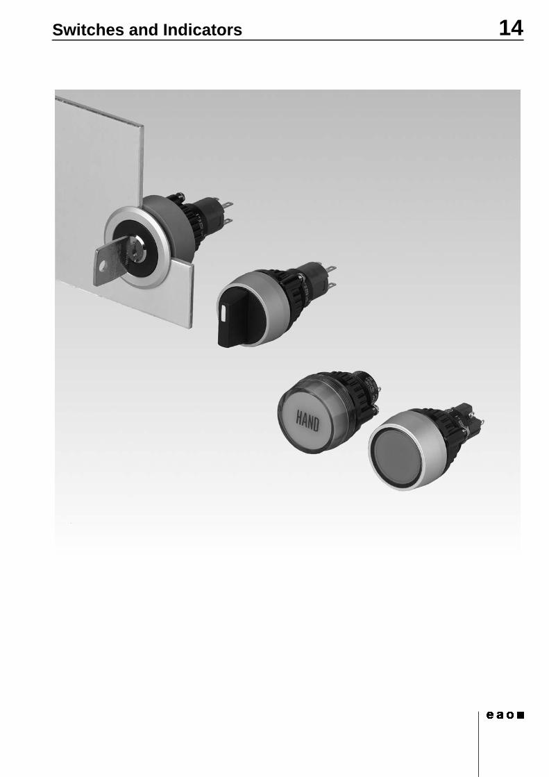
14Switches and Indicators
14Contents
207.2009
Description ...................................................................................................... 3
Product Assembly .......................................................................................... 4
Devices raised mounting ............................................................................... 6
Devices flush mounting ............................................................................... 13
Accessories................................................................................................... 17
Technical Data............................................................................................... 27
Typical Applications..................................................................................... 30
Application guidelines.................................................................................. 31
Marking .......................................................................................................... 32
Drawings........................................................................................................ 36
Index............................................................................................................... 56
307.2009
14Description
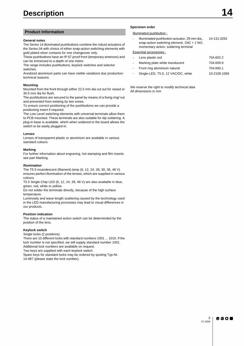
General notesThe Series 14 illuminated pushbuttons combine the robust actuators of the Series 04 with choice of either snap-action switching elements with gold plated silver contacts for one changeover only.These pushbuttons have an IP 67 proof front (temporary emerson) and can be immersed to a depth of one metre.The range includes pushbuttons, keylock switches and selector switches.Anodized aluminium parts can have visible variations due production-technical reasons.
MountingMounted from the front through either 22.5 mm dia cut out for raised or 30.5 mm dia for flush.The pushbuttons are secured to the panel by means of a fixing ring/ nut and prevented from twisting by two srews.To ensure correct positioning of the pushbuttons we can provide a positioning insert if required.The Low Level switching elements with universal terminals allow them to PCB mounted. These terminals are also suitable for dip soldering. A plug-in base is available, which when soldered to the board allows the switch to be easily plugged-in.
LensesLenses of transparent plastic or aluminium are available in various standard colours.
MarkingFor further information about engraving, hot stamping and film inserts see part Marking.
IlluminationThe T5.5 incandescent (filament) lamp (6, 12, 24, 28, 30, 36, 48 V) ensures perfect illumination of the lenses, which are supplied in various colours.T5.5 Single-Chip LED (6, 12, 24, 28, 48 V) are also available in blue, green, red, white or yellow.Do not solder the terminals directly, because of the high surface temperature.Luminosity and wave length scattering caused by the technology used in the LED manufacturing processes may lead to visual differences in our products.
Position indicationThe status of a maintained action switch can be determinded by the position of the lens.
Keylock switchSingle locks (2 positions).There are 10 different locks with standard numbers 1001 ... 1010. If the lock number is not specified, we will supply standard number 1001.Additional lock numbers are available on request.Two keys are supplied with each keylock switch.Spare keys for standard locks may be ordered by quoting Typ-Nr. 14-987 (please state the lock number).
Specimen order0
We reserve the right to modify technical dataAll dimensions in mm
Product Information Illuminated pushbutton :- Illuminiated pushbutton actuator, 29 mm dia.,
snap-action switching element, 1NC + 1 NO, momentary action, soldering terminal
14-131.0252
Essential accessories :- Lens plastic red 704.602.2- Marking plate white translucent 704.609.9- Front ring aluminium natural 704.600.1- Single-LED, T5.5, 12 VAC/DC, white 10-2109.1069
14Product Assembly
407.2009
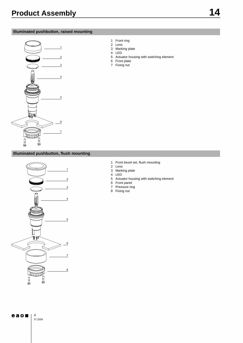
Illuminated pushbutton, raised mounting
0 1 Front ring2 Lens3 Marking plate4 LED5 Actuator housing with switching element6 Front plate7 Fixing nut
Illuminated pushbutton, flush mounting
0 1 Front bezel set, flush mounting2 Lens3 Marking plate4 LED5 Actuator housing with switching element6 Front panel7 Pressure ring8 Fixing nut
1
3
2
5
4
6
7
1
3
2
5
4
7
8
6
14Product Assembly
507.2009
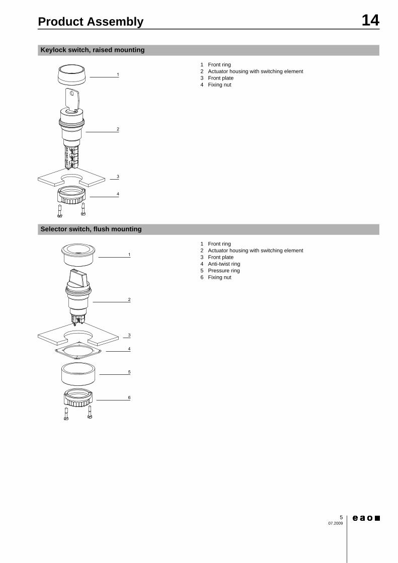
Keylock switch, raised mounting
0 1 Front ring2 Actuator housing with switching element3 Front plate4 Fixing nut
Selector switch, flush mounting
0 1 Front ring2 Actuator housing with switching element3 Front plate4 Anti-twist ring5 Pressure ring6 Fixing nut
1
3
2
4
1
3
2
5
4
6
14Devices raised mounting
607.2009
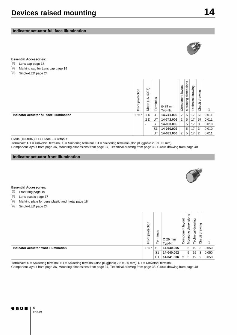
Essential Accessories:d Lens cap page 18d Marking cap for Lens cap page 19d Single-LED page 24Continuation see next page
Diode (1N 4007): D = Diode, - = withoutTerminals: UT = Universal terminal, S = Soldering terminal, S1 = Soldering terminal (also pluggable 2.8 x 0.5 mm)Component layout from page 36, Mounting dimensions from page 37, Technical drawing from page 38, Circuit drawing from page 48
Essential Accessories:d Front ring page 19d Lens plastic page 17d Marking plate for Lens plastic and metal page 18d Single-LED page 24Continuation see next page
Terminals: S = Soldering terminal, S1 = Soldering terminal (also pluggable 2.8 x 0.5 mm), UT = Universal terminalComponent layout from page 36, Mounting dimensions from page 37, Technical drawing from page 38, Circuit drawing from page 48
Indicator actuator full face illumination
Fron
t pro
tect
ion
Dio
de (1
N 4
007)
Term
inal
s
Ø 29 mmTyp-Nr. C
ompo
nent
layo
utM
ount
ing
dim
ensi
ons
Tech
nica
l dra
win
g
Circ
uit d
raw
ing
e
Indicator actuator full face illumination IP 67 1 D UT 14-741.006 2 5 17 56 0.0112 D UT 14-742.006 2 5 17 57 0.011- S 14-030.005 5 17 3 0.010
S1 14-030.002 5 17 3 0.010UT 14-031.006 2 5 17 2 0.011
Indicator actuator front illumination
Fron
t pro
tect
ion
Term
inal
s
Ø 29 mmTyp-Nr. C
ompo
nent
layo
utM
ount
ing
dim
ensi
ons
Tech
nica
l dra
win
g
Circ
uit d
raw
ing
e
Indicator actuator front illumination IP 67 S 14-040.005 5 19 3 0.050S1 14-040.002 5 19 3 0.050UT 14-041.006 2 5 19 2 0.050
14Devices raised mounting
707.2009
Continuation see next page
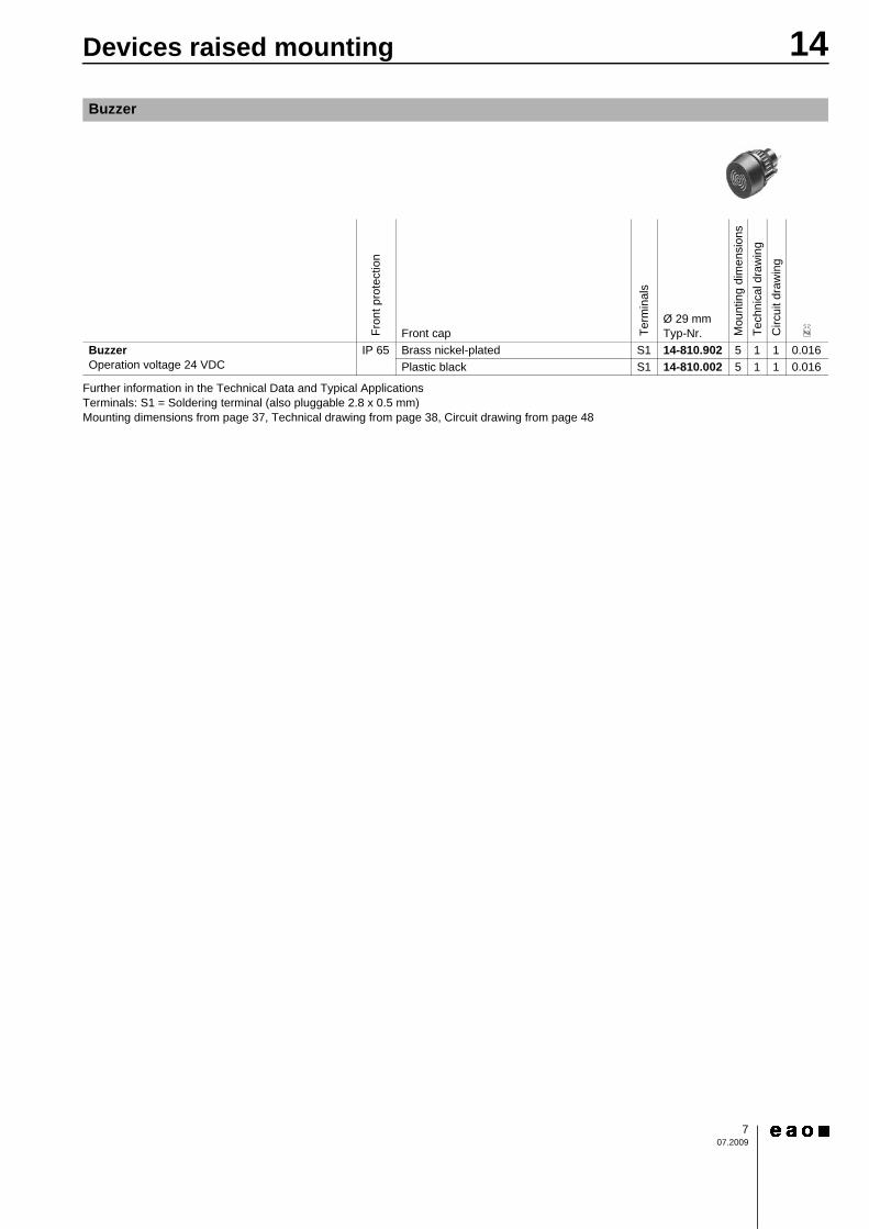
Further information in the Technical Data and Typical ApplicationsTerminals: S1 = Soldering terminal (also pluggable 2.8 x 0.5 mm)Mounting dimensions from page 37, Technical drawing from page 38, Circuit drawing from page 48
Buzzer
Fron
t pro
tect
ion
Front cap Term
inal
s
Ø 29 mmTyp-Nr. M
ount
ing
dim
ensi
ons
Tech
nica
l dra
win
gC
ircui
t dra
win
g
e
Buzzer Operation voltage 24 VDC
IP 65 Brass nickel-plated S1 14-810.902 5 1 1 0.016Plastic black S1 14-810.002 5 1 1 0.016
14Devices raised mounting
807.2009
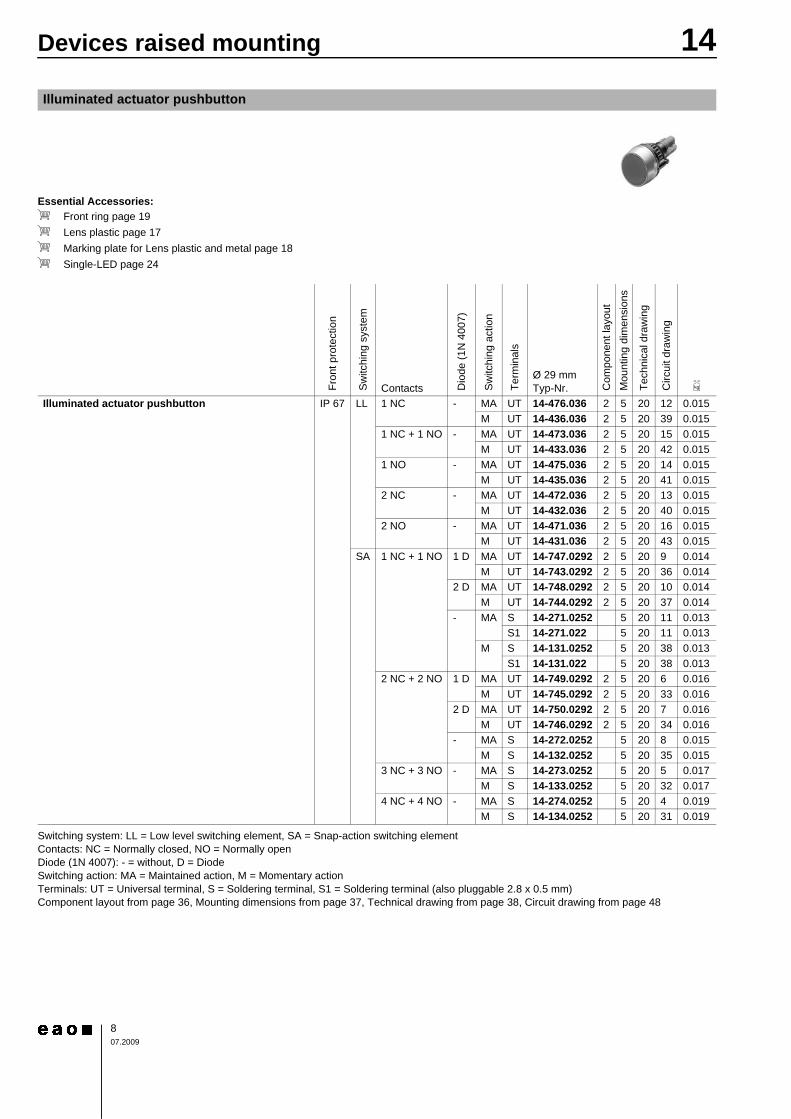
Essential Accessories:d Front ring page 19d Lens plastic page 17d Marking plate for Lens plastic and metal page 18d Single-LED page 24Continuation see next page
Switching system: LL = Low level switching element, SA = Snap-action switching elementContacts: NC = Normally closed, NO = Normally openDiode (1N 4007): - = without, D = DiodeSwitching action: MA = Maintained action, M = Momentary actionTerminals: UT = Universal terminal, S = Soldering terminal, S1 = Soldering terminal (also pluggable 2.8 x 0.5 mm)Component layout from page 36, Mounting dimensions from page 37, Technical drawing from page 38, Circuit drawing from page 48
Illuminated actuator pushbutton
Fron
t pro
tect
ion
Sw
itchi
ng s
yste
m
Contacts Dio
de (1
N 4
007)
Sw
itchi
ng a
ctio
n
Term
inal
s
Ø 29 mmTyp-Nr. C
ompo
nent
layo
utM
ount
ing
dim
ensi
ons
Tech
nica
l dra
win
g
Circ
uit d
raw
ing
e
Illuminated actuator pushbutton IP 67 LL 1 NC - MA UT 14-476.036 2 5 20 12 0.015M UT 14-436.036 2 5 20 39 0.015
1 NC + 1 NO - MA UT 14-473.036 2 5 20 15 0.015M UT 14-433.036 2 5 20 42 0.015
1 NO - MA UT 14-475.036 2 5 20 14 0.015M UT 14-435.036 2 5 20 41 0.015
2 NC - MA UT 14-472.036 2 5 20 13 0.015M UT 14-432.036 2 5 20 40 0.015
2 NO - MA UT 14-471.036 2 5 20 16 0.015M UT 14-431.036 2 5 20 43 0.015
SA 1 NC + 1 NO 1 D MA UT 14-747.0292 2 5 20 9 0.014M UT 14-743.0292 2 5 20 36 0.014
2 D MA UT 14-748.0292 2 5 20 10 0.014M UT 14-744.0292 2 5 20 37 0.014
- MA S 14-271.0252 5 20 11 0.013S1 14-271.022 5 20 11 0.013
M S 14-131.0252 5 20 38 0.013S1 14-131.022 5 20 38 0.013
2 NC + 2 NO 1 D MA UT 14-749.0292 2 5 20 6 0.016M UT 14-745.0292 2 5 20 33 0.016
2 D MA UT 14-750.0292 2 5 20 7 0.016M UT 14-746.0292 2 5 20 34 0.016
- MA S 14-272.0252 5 20 8 0.015M S 14-132.0252 5 20 35 0.015
3 NC + 3 NO - MA S 14-273.0252 5 20 5 0.017M S 14-133.0252 5 20 32 0.017
4 NC + 4 NO - MA S 14-274.0252 5 20 4 0.019M S 14-134.0252 5 20 31 0.019
14Devices raised mounting
907.2009
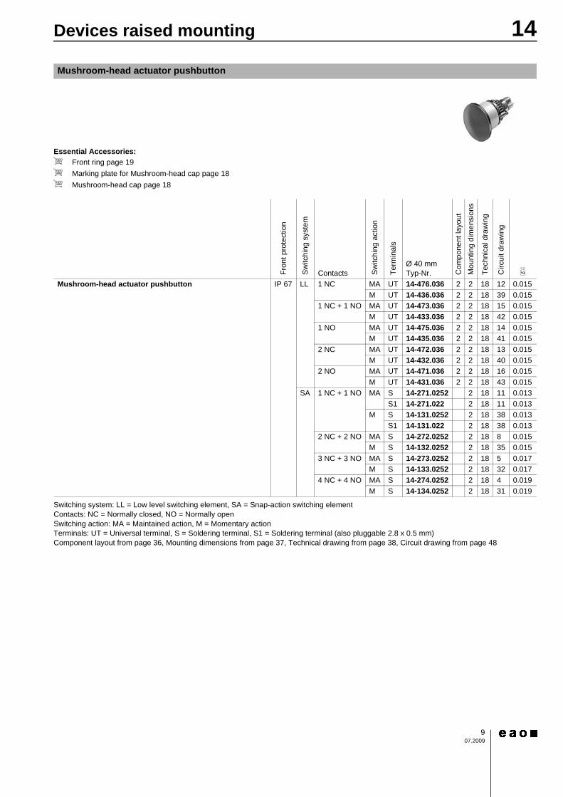
Essential Accessories:d Front ring page 19d Marking plate for Mushroom-head cap page 18d Mushroom-head cap page 18Continuation see next page
Switching system: LL = Low level switching element, SA = Snap-action switching elementContacts: NC = Normally closed, NO = Normally openSwitching action: MA = Maintained action, M = Momentary actionTerminals: UT = Universal terminal, S = Soldering terminal, S1 = Soldering terminal (also pluggable 2.8 x 0.5 mm)Component layout from page 36, Mounting dimensions from page 37, Technical drawing from page 38, Circuit drawing from page 48
Mushroom-head actuator pushbutton
Fron
t pro
tect
ion
Sw
itchi
ng s
yste
m
Contacts Sw
itchi
ng a
ctio
n
Term
inal
s
Ø 40 mmTyp-Nr. C
ompo
nent
layo
utM
ount
ing
dim
ensi
ons
Tech
nica
l dra
win
g
Circ
uit d
raw
ing
e
Mushroom-head actuator pushbutton IP 67 LL 1 NC MA UT 14-476.036 2 2 18 12 0.015M UT 14-436.036 2 2 18 39 0.015
1 NC + 1 NO MA UT 14-473.036 2 2 18 15 0.015M UT 14-433.036 2 2 18 42 0.015
1 NO MA UT 14-475.036 2 2 18 14 0.015M UT 14-435.036 2 2 18 41 0.015
2 NC MA UT 14-472.036 2 2 18 13 0.015M UT 14-432.036 2 2 18 40 0.015
2 NO MA UT 14-471.036 2 2 18 16 0.015M UT 14-431.036 2 2 18 43 0.015
SA 1 NC + 1 NO MA S 14-271.0252 2 18 11 0.013S1 14-271.022 2 18 11 0.013
M S 14-131.0252 2 18 38 0.013S1 14-131.022 2 18 38 0.013
2 NC + 2 NO MA S 14-272.0252 2 18 8 0.015M S 14-132.0252 2 18 35 0.015
3 NC + 3 NO MA S 14-273.0252 2 18 5 0.017M S 14-133.0252 2 18 32 0.017
4 NC + 4 NO MA S 14-274.0252 2 18 4 0.019M S 14-134.0252 2 18 31 0.019
14Devices raised mounting
1007.2009
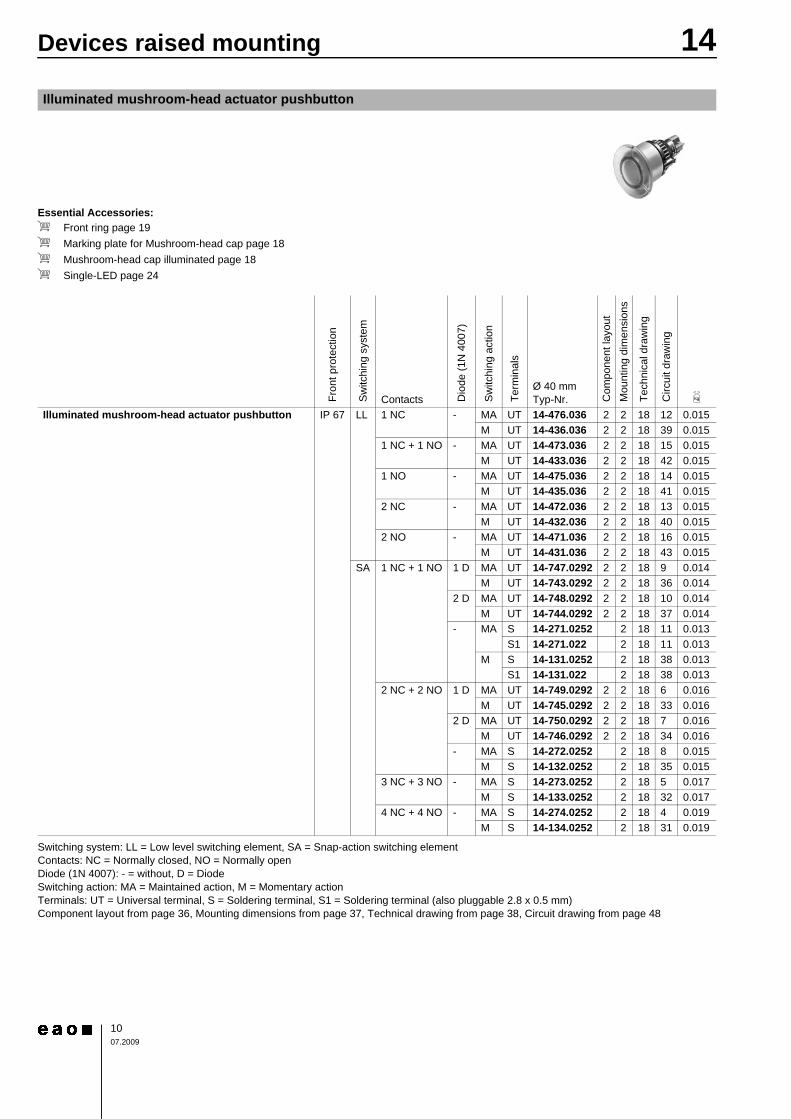
Essential Accessories:d Front ring page 19d Marking plate for Mushroom-head cap page 18d Mushroom-head cap illuminated page 18d Single-LED page 24Continuation see next page
Switching system: LL = Low level switching element, SA = Snap-action switching elementContacts: NC = Normally closed, NO = Normally openDiode (1N 4007): - = without, D = DiodeSwitching action: MA = Maintained action, M = Momentary actionTerminals: UT = Universal terminal, S = Soldering terminal, S1 = Soldering terminal (also pluggable 2.8 x 0.5 mm)Component layout from page 36, Mounting dimensions from page 37, Technical drawing from page 38, Circuit drawing from page 48
Illuminated mushroom-head actuator pushbutton
Fron
t pro
tect
ion
Sw
itchi
ng s
yste
m
Contacts Dio
de (1
N 4
007)
Sw
itchi
ng a
ctio
n
Term
inal
s
Ø 40 mmTyp-Nr. C
ompo
nent
layo
utM
ount
ing
dim
ensi
ons
Tech
nica
l dra
win
g
Circ
uit d
raw
ing
e
Illuminated mushroom-head actuator pushbutton IP 67 LL 1 NC - MA UT 14-476.036 2 2 18 12 0.015M UT 14-436.036 2 2 18 39 0.015
1 NC + 1 NO - MA UT 14-473.036 2 2 18 15 0.015M UT 14-433.036 2 2 18 42 0.015
1 NO - MA UT 14-475.036 2 2 18 14 0.015M UT 14-435.036 2 2 18 41 0.015
2 NC - MA UT 14-472.036 2 2 18 13 0.015M UT 14-432.036 2 2 18 40 0.015
2 NO - MA UT 14-471.036 2 2 18 16 0.015M UT 14-431.036 2 2 18 43 0.015
SA 1 NC + 1 NO 1 D MA UT 14-747.0292 2 2 18 9 0.014M UT 14-743.0292 2 2 18 36 0.014
2 D MA UT 14-748.0292 2 2 18 10 0.014M UT 14-744.0292 2 2 18 37 0.014
- MA S 14-271.0252 2 18 11 0.013S1 14-271.022 2 18 11 0.013
M S 14-131.0252 2 18 38 0.013S1 14-131.022 2 18 38 0.013
2 NC + 2 NO 1 D MA UT 14-749.0292 2 2 18 6 0.016M UT 14-745.0292 2 2 18 33 0.016
2 D MA UT 14-750.0292 2 2 18 7 0.016M UT 14-746.0292 2 2 18 34 0.016
- MA S 14-272.0252 2 18 8 0.015M S 14-132.0252 2 18 35 0.015
3 NC + 3 NO - MA S 14-273.0252 2 18 5 0.017M S 14-133.0252 2 18 32 0.017
4 NC + 4 NO - MA S 14-274.0252 2 18 4 0.019M S 14-134.0252 2 18 31 0.019
14Devices raised mounting
1107.2009
Continuation see next page
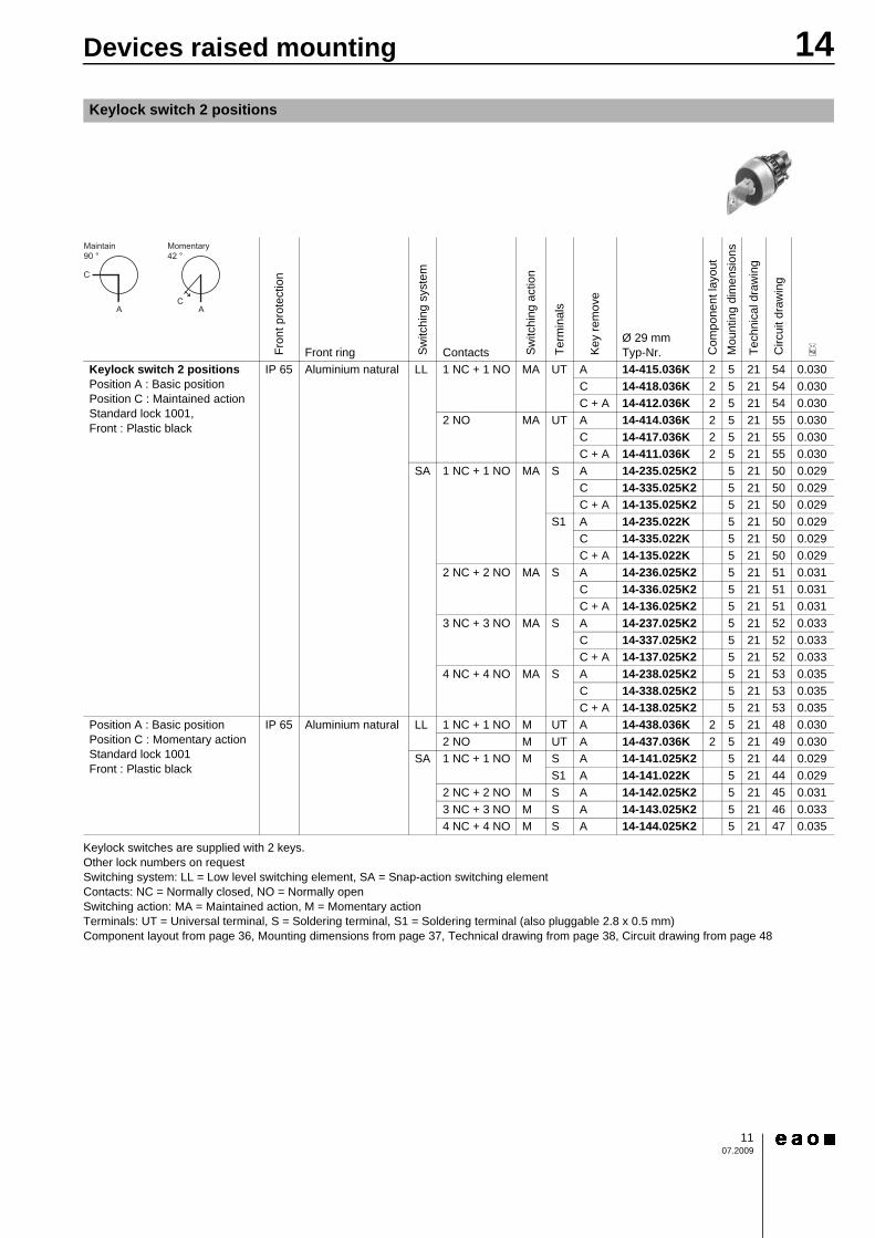
Keylock switches are supplied with 2 keys.Other lock numbers on requestSwitching system: LL = Low level switching element, SA = Snap-action switching elementContacts: NC = Normally closed, NO = Normally openSwitching action: MA = Maintained action, M = Momentary actionTerminals: UT = Universal terminal, S = Soldering terminal, S1 = Soldering terminal (also pluggable 2.8 x 0.5 mm)Component layout from page 36, Mounting dimensions from page 37, Technical drawing from page 38, Circuit drawing from page 48
Keylock switch 2 positions
0
Fron
t pro
tect
ion
Front ring Switc
hing
sys
tem
Contacts Switc
hing
act
ion
Term
inal
s
Key
rem
ove
Ø 29 mmTyp-Nr. C
ompo
nent
layo
utM
ount
ing
dim
ensi
ons
Tech
nica
l dra
win
g
Circ
uit d
raw
ing
e
Keylock switch 2 positions Position A : Basic positionPosition C : Maintained action Standard lock 1001,Front : Plastic black
IP 65 Aluminium natural LL 1 NC + 1 NO MA UT A 14-415.036K 2 5 21 54 0.030C 14-418.036K 2 5 21 54 0.030C + A 14-412.036K 2 5 21 54 0.030
2 NO MA UT A 14-414.036K 2 5 21 55 0.030C 14-417.036K 2 5 21 55 0.030C + A 14-411.036K 2 5 21 55 0.030
SA 1 NC + 1 NO MA S A 14-235.025K2 5 21 50 0.029C 14-335.025K2 5 21 50 0.029C + A 14-135.025K2 5 21 50 0.029
S1 A 14-235.022K 5 21 50 0.029C 14-335.022K 5 21 50 0.029C + A 14-135.022K 5 21 50 0.029
2 NC + 2 NO MA S A 14-236.025K2 5 21 51 0.031C 14-336.025K2 5 21 51 0.031C + A 14-136.025K2 5 21 51 0.031
3 NC + 3 NO MA S A 14-237.025K2 5 21 52 0.033C 14-337.025K2 5 21 52 0.033C + A 14-137.025K2 5 21 52 0.033
4 NC + 4 NO MA S A 14-238.025K2 5 21 53 0.035C 14-338.025K2 5 21 53 0.035C + A 14-138.025K2 5 21 53 0.035
Position A : Basic positionPosition C : Momentary action Standard lock 1001Front : Plastic black
IP 65 Aluminium natural LL 1 NC + 1 NO M UT A 14-438.036K 2 5 21 48 0.0302 NO M UT A 14-437.036K 2 5 21 49 0.030
SA 1 NC + 1 NO M S A 14-141.025K2 5 21 44 0.029S1 A 14-141.022K 5 21 44 0.029
2 NC + 2 NO M S A 14-142.025K2 5 21 45 0.0313 NC + 3 NO M S A 14-143.025K2 5 21 46 0.0334 NC + 4 NO M S A 14-144.025K2 5 21 47 0.035
14Devices raised mounting
1207.2009
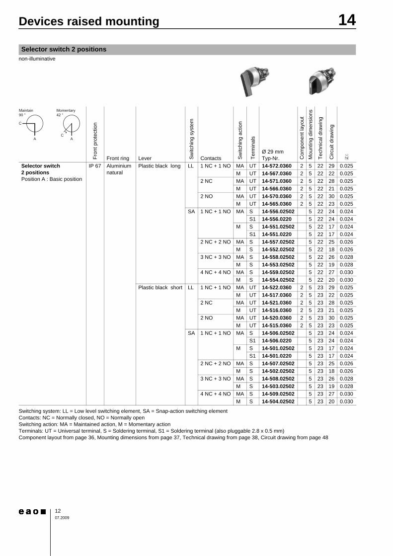
non-illuminative
Continuation see next page
Switching system: LL = Low level switching element, SA = Snap-action switching elementContacts: NC = Normally closed, NO = Normally openSwitching action: MA = Maintained action, M = Momentary actionTerminals: UT = Universal terminal, S = Soldering terminal, S1 = Soldering terminal (also pluggable 2.8 x 0.5 mm)Component layout from page 36, Mounting dimensions from page 37, Technical drawing from page 38, Circuit drawing from page 48
Selector switch 2 positions
0
Fron
t pro
tect
ion
Front ring Lever Switc
hing
sys
tem
Contacts Switc
hing
act
ion
Term
inal
s
Ø 29 mmTyp-Nr. C
ompo
nent
layo
utM
ount
ing
dim
ensi
ons
Tech
nica
l dra
win
g
Circ
uit d
raw
ing
e
Selector switch 2 positions Position A : Basic position
IP 67 Aluminium natural
Plastic black long LL 1 NC + 1 NO MA UT 14-572.0360 2 5 22 29 0.025M UT 14-567.0360 2 5 22 22 0.025
2 NC MA UT 14-571.0360 2 5 22 28 0.025M UT 14-566.0360 2 5 22 21 0.025
2 NO MA UT 14-570.0360 2 5 22 30 0.025M UT 14-565.0360 2 5 22 23 0.025
SA 1 NC + 1 NO MA S 14-556.02502 5 22 24 0.024S1 14-556.0220 5 22 24 0.024
M S 14-551.02502 5 22 17 0.024S1 14-551.0220 5 22 17 0.024
2 NC + 2 NO MA S 14-557.02502 5 22 25 0.026M S 14-552.02502 5 22 18 0.026
3 NC + 3 NO MA S 14-558.02502 5 22 26 0.028M S 14-553.02502 5 22 19 0.028
4 NC + 4 NO MA S 14-559.02502 5 22 27 0.030M S 14-554.02502 5 22 20 0.030
Plastic black short LL 1 NC + 1 NO MA UT 14-522.0360 2 5 23 29 0.025M UT 14-517.0360 2 5 23 22 0.025
2 NC MA UT 14-521.0360 2 5 23 28 0.025M UT 14-516.0360 2 5 23 21 0.025
2 NO MA UT 14-520.0360 2 5 23 30 0.025M UT 14-515.0360 2 5 23 23 0.025
SA 1 NC + 1 NO MA S 14-506.02502 5 23 24 0.024S1 14-506.0220 5 23 24 0.024
M S 14-501.02502 5 23 17 0.024S1 14-501.0220 5 23 17 0.024
2 NC + 2 NO MA S 14-507.02502 5 23 25 0.026M S 14-502.02502 5 23 18 0.026
3 NC + 3 NO MA S 14-508.02502 5 23 26 0.028M S 14-503.02502 5 23 19 0.028
4 NC + 4 NO MA S 14-509.02502 5 23 27 0.030M S 14-504.02502 5 23 20 0.030
14Devices flush mounting
1307.2009
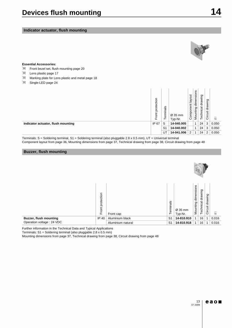
Essential Accessories:d Front bezel set, flush mounting page 20d Lens plastic page 17d Marking plate for Lens plastic and metal page 18d Single-LED page 24Continuation see next page
Terminals: S = Soldering terminal, S1 = Soldering terminal (also pluggable 2.8 x 0.5 mm), UT = Universal terminalComponent layout from page 36, Mounting dimensions from page 37, Technical drawing from page 38, Circuit drawing from page 48
Continuation see next page
Further information in the Technical Data and Typical ApplicationsTerminals: S1 = Soldering terminal (also pluggable 2.8 x 0.5 mm)Mounting dimensions from page 37, Technical drawing from page 38, Circuit drawing from page 48
Indicator actuator, flush mounting
Fron
t pro
tect
ion
Term
inal
s
Ø 35 mmTyp-Nr. C
ompo
nent
layo
utM
ount
ing
dim
ensi
ons
Tech
nica
l dra
win
g
Circ
uit d
raw
ing
e
Indicator actuator, flush mounting IP 67 S 14-040.005 1 24 3 0.050S1 14-040.002 1 24 3 0.050UT 14-041.006 2 1 24 2 0.050
Buzzer, flush mounting
Fron
t pro
tect
ion
Front cap Term
inal
s
Ø 35 mmTyp-Nr. M
ount
ing
dim
ensi
ons
Tech
nica
l dra
win
g
Circ
uit d
raw
ing
e
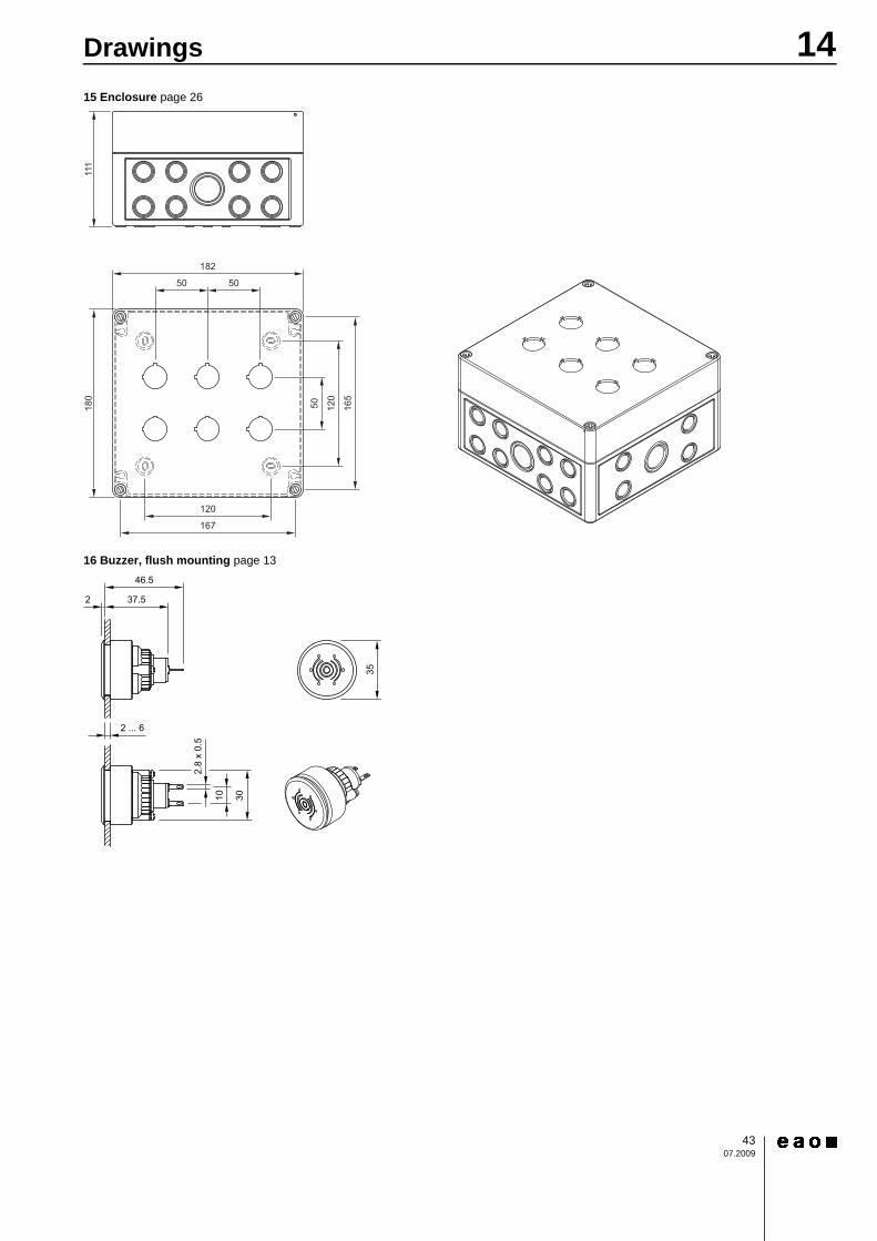
Buzzer, flush mounting Operation voltage : 24 VDC
IP 40 Aluminium black S1 14-810.910 1 16 1 0.016Aluminium natural S1 14-810.918 1 16 1 0.016

14Devices flush mounting
1407.2009
Essential Accessories:d Front bezel set, flush mounting page 20d Lens plastic page 17d Marking plate for Lens plastic and metal page 18d Single-LED page 24Continuation see next page
Switching system: LL = Low level switching element, SA = Snap-action switching elementContacts: NC = Normally closed, NO = Normally openDiode (1N 4007): - = without, D = DiodeSwitching action: MA = Maintained action, M = Momentary actionTerminals: UT = Universal terminal, S = Soldering terminal, S1 = Soldering terminal (also pluggable 2.8 x 0.5 mm)Component layout from page 36, Mounting dimensions from page 37, Technical drawing from page 38, Circuit drawing from page 48
Illuminated pushbutton actuator, flush mounting
Fron
t pro
tect
ion
Sw
itchi
ng s
yste
m
Contacts Dio
de (1
N 4
007)
Sw
itchi
ng a
ctio
n
Term
inal
s
Ø 35 mmTyp-Nr. C
ompo
nent
layo
utM
ount
ing
dim
ensi
ons
Tech
nica
l dra
win
g
Circ
uit d
raw
ing
e
Illuminated pushbutton actuator, flush mounting IP 67 LL 1 NC - MA UT 14-476.036 2 1 25 12 0.015M UT 14-436.036 2 1 25 39 0.015
1 NC + 1 NO - MA UT 14-473.036 2 1 25 15 0.015M UT 14-433.036 2 1 25 42 0.015
1 NO - MA UT 14-475.036 2 1 25 14 0.015M UT 14-435.036 2 1 25 41 0.015
2 NC - MA UT 14-472.036 2 1 25 13 0.015M UT 14-432.036 2 1 25 40 0.015
2 NO - MA UT 14-471.036 2 1 25 16 0.015M UT 14-431.036 2 1 25 43 0.015
SA 1 NC + 1 NO 1 D MA UT 14-747.0292 2 1 25 9 0.014M UT 14-743.0292 2 1 25 36 0.014
2 D MA UT 14-748.0292 2 1 25 10 0.014M UT 14-744.0292 2 1 25 37 0.014
- MA S 14-271.0252 1 25 11 0.013S1 14-271.022 1 25 11 0.013
M S 14-131.0252 1 25 38 0.013S1 14-131.022 1 25 38 0.013
2 NC + 2 NO 1 D MA UT 14-749.0292 2 1 25 6 0.016M UT 14-745.0292 2 1 25 33 0.016
2 D MA UT 14-750.0292 2 1 25 7 0.016M UT 14-746.0292 2 1 25 34 0.016
- MA S 14-272.0252 1 25 8 0.015M S 14-132.0252 1 25 35 0.015
3 NC + 3 NO - MA S 14-273.0252 1 25 5 0.017M S 14-133.0252 1 25 32 0.017
4 NC + 4 NO - MA S 14-274.0252 1 25 4 0.019M S 14-134.0252 1 25 31 0.019
14Devices flush mounting
1507.2009
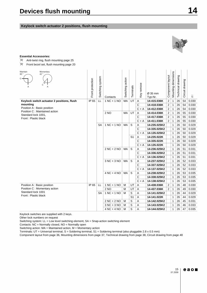
Essential Accessories:d Anti-twist ring, flush mounting page 25d Front bezel set, flush mounting page 20Continuation see next page
Keylock switches are supplied with 2 keys.Other lock numbers on requestSwitching system: LL = Low level switching element, SA = Snap-action switching elementContacts: NC = Normally closed, NO = Normally openSwitching action: MA = Maintained action, M = Momentary actionTerminals: UT = Universal terminal, S = Soldering terminal, S1 = Soldering terminal (also pluggable 2.8 x 0.5 mm)Component layout from page 36, Mounting dimensions from page 37, Technical drawing from page 38, Circuit drawing from page 48
Keylock switch actuator 2 positions, flush mounting
0
Fron
t pro
tect
ion
Sw
itchi
ng s
yste
mContacts S
witc
hing
act
ion
Term
inal
s
Key
rem
ove
Ø 35 mmTyp-Nr. C
ompo
nent
layo
utM
ount
ing
dim
ensi
ons
Tech
nica
l dra
win
g
Circ
uit d
raw
ing
e
Keylock switch actuator 2 positions, flush mounting Position A : Basic positionPosition C : Maintained action Standard lock 1001,Front : Plastic black
IP 65 LL 1 NC + 1 NO MA UT A 14-415.036K 2 1 26 54 0.030C 14-418.036K 2 1 26 54 0.030C + A 14-412.036K 2 1 26 54 0.030
2 NO MA UT A 14-414.036K 2 1 26 55 0.030C 14-417.036K 2 1 26 55 0.030C + A 14-411.036K 2 1 26 55 0.030
SA 1 NC + 1 NO MA S A 14-235.025K2 1 26 50 0.029C 14-335.025K2 1 26 50 0.029C + A 14-135.025K2 1 26 50 0.029
S1 A 14-235.022K 1 26 50 0.029C 14-335.022K 1 26 50 0.029C + A 14-135.022K 1 26 50 0.029
2 NC + 2 NO MA S A 14-236.025K2 1 26 51 0.031C 14-336.025K2 1 26 51 0.031C + A 14-136.025K2 1 26 51 0.031
3 NC + 3 NO MA S A 14-237.025K2 1 26 52 0.033C 14-337.025K2 1 26 52 0.033C + A 14-137.025K2 1 26 52 0.033
4 NC + 4 NO MA S A 14-238.025K2 1 26 53 0.035C 14-338.025K2 1 26 53 0.035C + A 14-138.025K2 1 26 53 0.035
Position A : Basic positionPosition C : Momentary action Standard lock 1001Front : Plastic black
IP 65 LL 1 NC + 1 NO M UT A 14-438.036K 2 1 26 48 0.0302 NO M UT A 14-437.036K 2 1 26 49 0.030
SA 1 NC + 1 NO M S A 14-141.025K2 1 26 44 0.029S1 A 14-141.022K 1 26 44 0.029
2 NC + 2 NO M S A 14-142.025K2 1 26 45 0.0313 NC + 3 NO M S A 14-143.025K2 1 26 46 0.0334 NC + 4 NO M S A 14-144.025K2 1 26 47 0.035
14Devices flush mounting
1607.2009
Essential Accessories:d Anti-twist ring, flush mounting page 25d Front bezel set, flush mounting page 20Continuation see next page
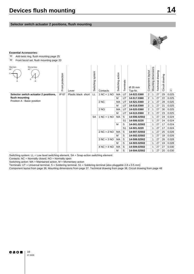
Switching system: LL = Low level switching element, SA = Snap-action switching elementContacts: NC = Normally closed, NO = Normally openSwitching action: MA = Maintained action, M = Momentary actionTerminals: UT = Universal terminal, S = Soldering terminal, S1 = Soldering terminal (also pluggable 2.8 x 0.5 mm)Component layout from page 36, Mounting dimensions from page 37, Technical drawing from page 38, Circuit drawing from page 48
Selector switch actuator 2 positions, flush mounting
0
Fron
t pro
tect
ion
Lever Sw
itchi
ng s
yste
mContacts S
witc
hing
act
ion
Term
inal
s
Ø 35 mmTyp-Nr. C
ompo
nent
layo
utM
ount
ing
dim
ensi
ons
Tech
nica
l dra
win
g
Circ
uit d
raw
ing
e
Selector switch actuator 2 positions, flush mounting Position A : Basic position
IP 67 Plastic black short LL 1 NC + 1 NO MA UT 14-522.0360 2 1 27 29 0.025M UT 14-517.0360 2 1 27 22 0.025
2 NC MA UT 14-521.0360 2 1 27 28 0.025M UT 14-516.0360 2 1 27 21 0.025
2 NO MA UT 14-520.0360 2 1 27 30 0.025M UT 14-515.0360 2 1 27 23 0.025
SA 1 NC + 1 NO MA S 14-506.02502 1 27 24 0.024S1 14-506.0220 1 27 24 0.024
M S 14-501.02502 1 27 17 0.024S1 14-501.0220 1 27 17 0.024
2 NC + 2 NO MA S 14-507.02502 1 27 25 0.026M S 14-502.02502 1 27 18 0.026
3 NC + 3 NO MA S 14-508.02502 1 27 26 0.028M S 14-503.02502 1 27 19 0.028
4 NC + 4 NO MA S 14-509.02502 1 27 27 0.030M S 14-504.02502 1 27 20 0.030
1707.2009
14Accessories
To obtain IP 67 use Marking plate Typ-Nr. 704.609.XContinuation see next page
To obtain IP 67 use Marking plate Typ-Nr. 704.610.XContinuation see next page
To obtain IP 67 use Marking plate Typ-Nr. 704.609.XContinuation see next page
To obtain IP 67 use Marking plate Typ-Nr. 704.609.9Continuation see next page
Front
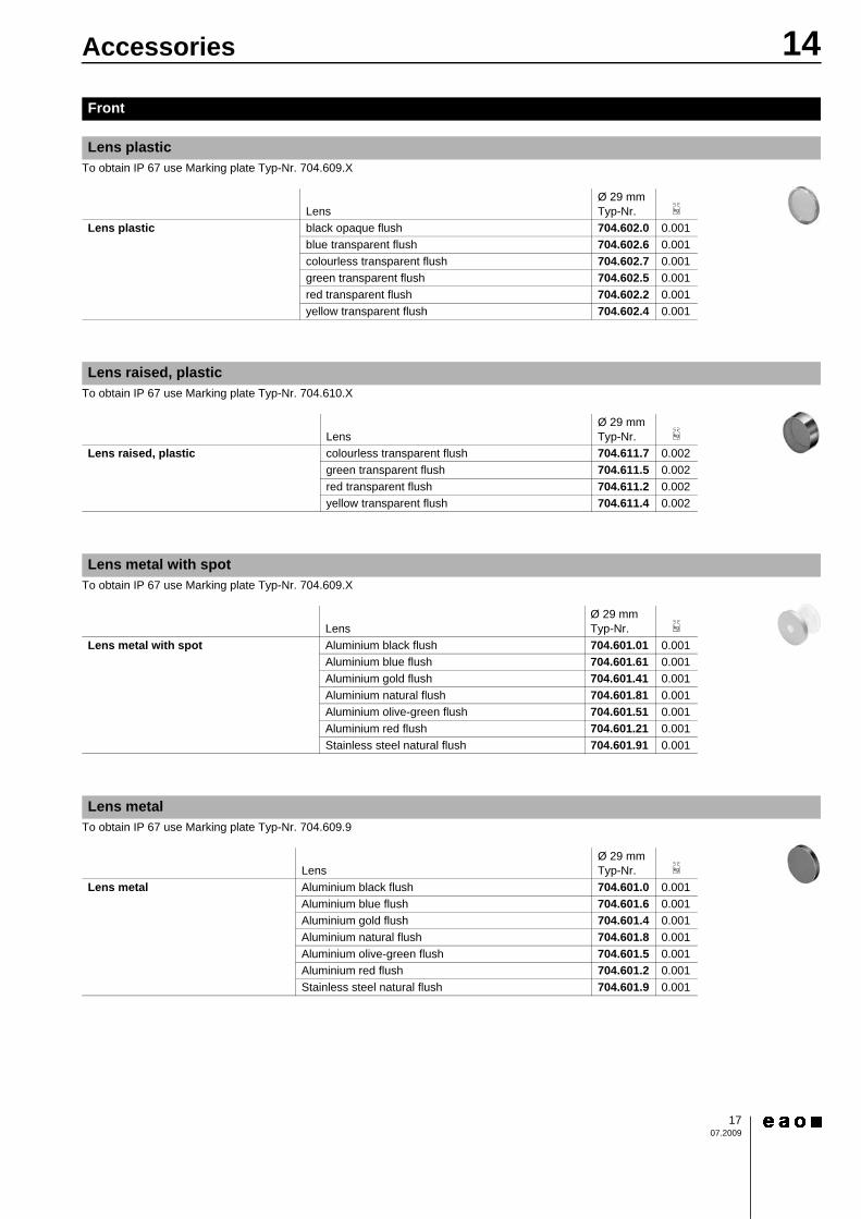
Lens plastic
LensØ 29 mmTyp-Nr. e
Lens plastic black opaque flush 704.602.0 0.001blue transparent flush 704.602.6 0.001colourless transparent flush 704.602.7 0.001green transparent flush 704.602.5 0.001red transparent flush 704.602.2 0.001yellow transparent flush 704.602.4 0.001
Lens raised, plastic
LensØ 29 mmTyp-Nr. e
Lens raised, plastic colourless transparent flush 704.611.7 0.002green transparent flush 704.611.5 0.002red transparent flush 704.611.2 0.002yellow transparent flush 704.611.4 0.002
Lens metal with spot
LensØ 29 mmTyp-Nr. e
Lens metal with spot Aluminium black flush 704.601.01 0.001Aluminium blue flush 704.601.61 0.001Aluminium gold flush 704.601.41 0.001Aluminium natural flush 704.601.81 0.001Aluminium olive-green flush 704.601.51 0.001Aluminium red flush 704.601.21 0.001Stainless steel natural flush 704.601.91 0.001
Lens metal
LensØ 29 mmTyp-Nr. e
Lens metal Aluminium black flush 704.601.0 0.001Aluminium blue flush 704.601.6 0.001Aluminium gold flush 704.601.4 0.001Aluminium natural flush 704.601.8 0.001Aluminium olive-green flush 704.601.5 0.001Aluminium red flush 704.601.2 0.001Stainless steel natural flush 704.601.9 0.001
1807.2009
14Accessories
To obtain IP 67 use Marking plate Typ-Nr. 704.608.XContinuation see next page
To obtain IP 67 use Marking plate Typ-Nr. 704.609.9Continuation see next page
To obtain IP 67 use Marking plate Typ-Nr. 704.609.9Continuation see next page
Continuation see next page
Continuation see next page
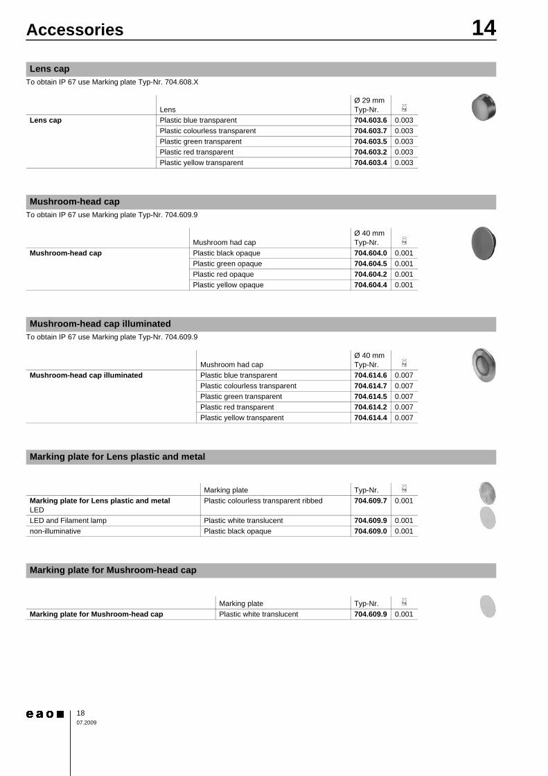
Lens cap
LensØ 29 mmTyp-Nr. e
Lens cap Plastic blue transparent 704.603.6 0.003Plastic colourless transparent 704.603.7 0.003Plastic green transparent 704.603.5 0.003Plastic red transparent 704.603.2 0.003Plastic yellow transparent 704.603.4 0.003
Mushroom-head cap
Mushroom had capØ 40 mmTyp-Nr. e
Mushroom-head cap Plastic black opaque 704.604.0 0.001Plastic green opaque 704.604.5 0.001Plastic red opaque 704.604.2 0.001Plastic yellow opaque 704.604.4 0.001
Mushroom-head cap illuminated
Mushroom had capØ 40 mmTyp-Nr. e
Mushroom-head cap illuminated Plastic blue transparent 704.614.6 0.007Plastic colourless transparent 704.614.7 0.007Plastic green transparent 704.614.5 0.007Plastic red transparent 704.614.2 0.007Plastic yellow transparent 704.614.4 0.007
Marking plate for Lens plastic and metal
Marking plate Typ-Nr. e
Marking plate for Lens plastic and metal LED
Plastic colourless transparent ribbed 704.609.7 0.001
LED and Filament lamp Plastic white translucent 704.609.9 0.001non-illuminative Plastic black opaque 704.609.0 0.001
Marking plate for Mushroom-head cap
Marking plate Typ-Nr. e
Marking plate for Mushroom-head cap Plastic white translucent 704.609.9 0.001

1907.2009
14Accessories
Continuation see next page
Continuation see next page
Continuation see next page
Continuation see next page
Mounting dimensions from page 37, Technical drawing from page 38
Marking cap for Lens raised, plastic
Marking cap Typ-Nr. e
Marking cap for Lens raised, plastic LED
Plastic colourless transparent ribbed 704.610.7 0.001
LED and Filament lamp Plastic white translucent 704.610.9 0.001
Marking cap for Lens cap
Marking cap Typ-Nr. e
Marking cap for Lens cap LED
Plastic colourless transparent ribbed 704.608.7 0.002
LED and Filament lamp Plastic white translucent 704.608.9 0.002
Front ring
Ø 29 mmTyp-Nr. e
Front ring 704.600.0 0.003704.600.6 0.003704.600.1 0.005704.600.1A 0.005704.600.9 0.006
Front bezel set for Mushroom-head pushbutton
Front BezelØ 50 mmTyp-Nr. M
ount
ing
dim
ensi
ons
Tech
nica
l dra
win
g
e
Front bezel set for Mushroom-head pushbutton Aluminium black 14-958.0 4 28 0.042Aluminium natural 14-958.8 4 28 0.042
2007.2009
14Accessories
Continuation see next page
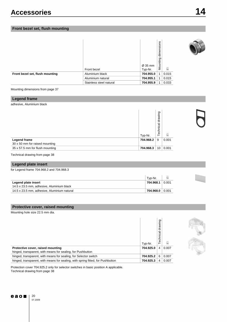
Mounting dimensions from page 37
adhesive, Aluminium blackContinuation see next page
Technical drawing from page 38
for Legend frame 704.968.2 and 704.968.3Continuation see next page
Mounting hole size 22.5 mm dia.Continuation see next page
Protection cover 704.925.2 only for selector switches in basic position A applicable.Technical drawing from page 38
Front bezel set, flush mounting
Front bezelØ 35 mmTyp-Nr. M
ount
ing
dim
ensi
ons
e
Front bezel set, flush mounting Aluminium black 704.955.0 1 0.015Aluminium natural 704.955.1 1 0.015Stainless steel natural 704.955.9 1 0.033
Legend frame
Typ-Nr. Tech
nica
l dra
win
g
e
Legend frame 30 x 50 mm for raised mounting
704.968.2 9 0.001
35 x 57.5 mm for flush mounting 704.968.3 10 0.001
Legend plate insert
Typ-Nr. e
Legend plate insert 14.5 x 23.5 mm, adhesive, Aluminium black
704.968.1 0.001
14.5 x 23.5 mm, adhesive, Aluminium natural 704.968.0 0.001
Protective cover, raised mounting
Typ-Nr. Tech
nica
l dra
win
g
e
Protective cover, raised mounting hinged, transparent, with means for sealing, for Pushbutton
704.925.0 4 0.007
hinged, transparent, with means for sealing, for Selector switch 704.925.2 6 0.007hinged, transparent, with means for sealing, with spring fitted, for Pushbutton 704.925.3 4 0.007
2107.2009
14Accessories
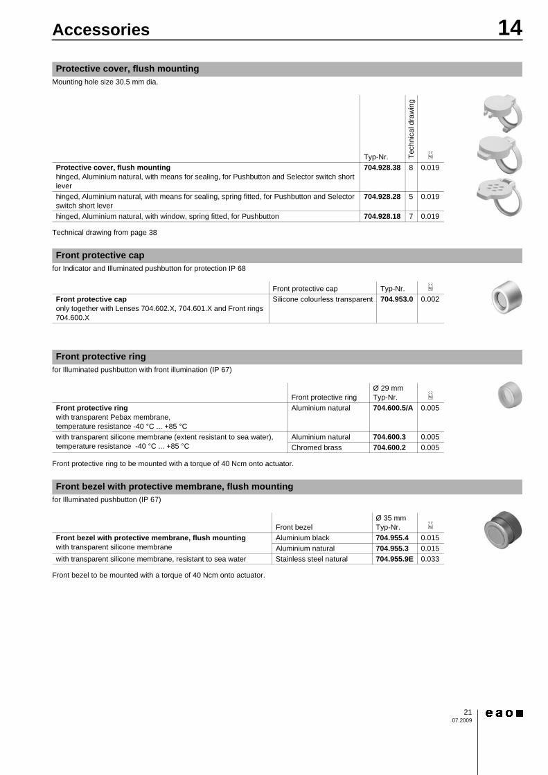
Mounting hole size 30.5 mm dia.Continuation see next page
Technical drawing from page 38
for Indicator and Illuminated pushbutton for protection IP 68Continuation see next page
for Illuminated pushbutton with front illumination (IP 67)Continuation see next page
Front protective ring to be mounted with a torque of 40 Ncm onto actuator.
for Illuminated pushbutton (IP 67)Continuation see next page
Front bezel to be mounted with a torque of 40 Ncm onto actuator.
Protective cover, flush mounting
Typ-Nr. Tech
nica
l dra
win
g
e
Protective cover, flush mounting hinged, Aluminium natural, with means for sealing, for Pushbutton and Selector switch short lever
704.928.38 8 0.019
hinged, Aluminium natural, with means for sealing, spring fitted, for Pushbutton and Selector switch short lever
704.928.28 5 0.019
hinged, Aluminium natural, with window, spring fitted, for Pushbutton 704.928.18 7 0.019
Front protective cap
Front protective cap Typ-Nr. e
Front protective cap only together with Lenses 704.602.X, 704.601.X and Front rings 704.600.X
Silicone colourless transparent 704.953.0 0.002
Front protective ring
Front protective ringØ 29 mmTyp-Nr. e
Front protective ring with transparent Pebax membrane, temperature resistance -40 °C ... +85 °C
Aluminium natural 704.600.5/A 0.005
with transparent silicone membrane (extent resistant to sea water), temperature resistance -40 °C ... +85 °C
Aluminium natural 704.600.3 0.005Chromed brass 704.600.2 0.005
Front bezel with protective membrane, flush mounting
Front bezelØ 35 mmTyp-Nr. e
Front bezel with protective membrane, flush mounting with transparent silicone membrane
Aluminium black 704.955.4 0.015Aluminium natural 704.955.3 0.015
with transparent silicone membrane, resistant to sea water Stainless steel natural 704.955.9E 0.033
2207.2009
14Accessories
Continuation see next page
Technical drawing from page 38
Continuation see next page
Other lock numbers on request
>
Continuation see next page
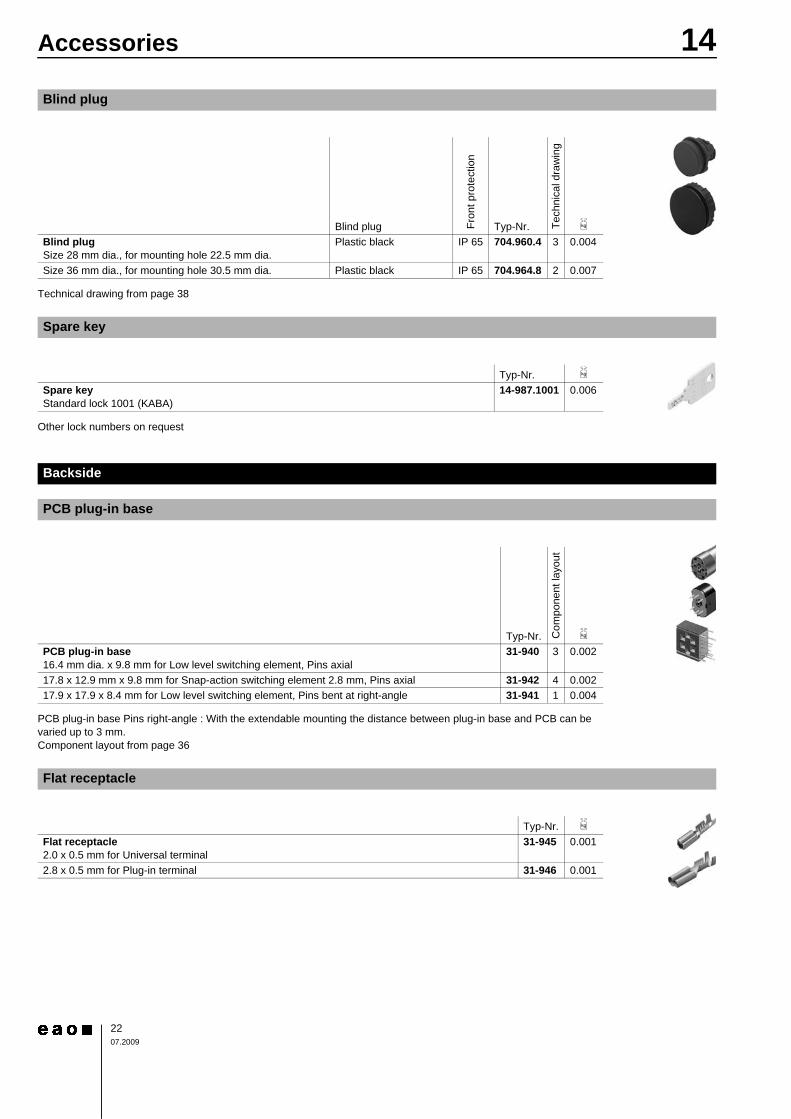
PCB plug-in base Pins right-angle : With the extendable mounting the distance between plug-in base and PCB can be varied up to 3 mm.Component layout from page 36
Continuation see next page
Blind plug
Blind plug Fron
t pro
tect
ion
Typ-Nr. Tech
nica
l dra
win
g
e
Blind plug Size 28 mm dia., for mounting hole 22.5 mm dia.
Plastic black IP 65 704.960.4 3 0.004
Size 36 mm dia., for mounting hole 30.5 mm dia. Plastic black IP 65 704.964.8 2 0.007
Spare key
Typ-Nr. e
Spare key Standard lock 1001 (KABA)
14-987.1001 0.006
Backside
PCB plug-in base
Typ-Nr. Com
pone
nt la
yout
e
PCB plug-in base 16.4 mm dia. x 9.8 mm for Low level switching element, Pins axial
31-940 3 0.002
17.8 x 12.9 mm x 9.8 mm for Snap-action switching element 2.8 mm, Pins axial 31-942 4 0.00217.9 x 17.9 x 8.4 mm for Low level switching element, Pins bent at right-angle 31-941 1 0.004
Flat receptacle
Typ-Nr. e
Flat receptacle 2.0 x 0.5 mm for Universal terminal
31-945 0.001
2.8 x 0.5 mm for Plug-in terminal 31-946 0.001
2307.2009
14Accessories
Continuation see next page
Continuation see next page
>
Continuation see next page
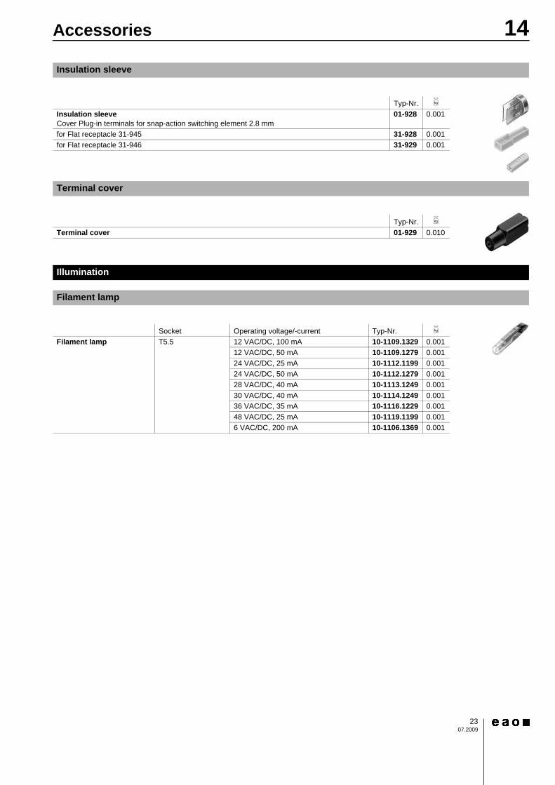
Insulation sleeve
Typ-Nr. e
Insulation sleeve Cover Plug-in terminals for snap-action switching element 2.8 mm
01-928 0.001
for Flat receptacle 31-945 31-928 0.001for Flat receptacle 31-946 31-929 0.001
Terminal cover
Typ-Nr. e
Terminal cover 01-929 0.010
Illumination
Filament lamp
Socket Operating voltage/-current Typ-Nr. e
Filament lamp T5.5 12 VAC/DC, 100 mA 10-1109.1329 0.00112 VAC/DC, 50 mA 10-1109.1279 0.00124 VAC/DC, 25 mA 10-1112.1199 0.00124 VAC/DC, 50 mA 10-1112.1279 0.00128 VAC/DC, 40 mA 10-1113.1249 0.00130 VAC/DC, 40 mA 10-1114.1249 0.00136 VAC/DC, 35 mA 10-1116.1229 0.00148 VAC/DC, 25 mA 10-1119.1199 0.0016 VAC/DC, 200 mA 10-1106.1369 0.001
2407.2009
14Accessories
Continuation see next page
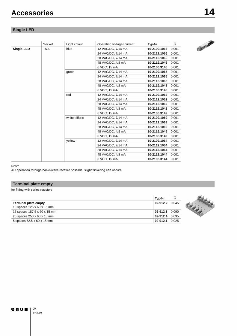
Note:AC operation through halve-wave rectifier possible, slight flickering can occure.
for fitting with series resistorsContinuation see next page
Single-LED
Socket Light colour Operating voltage/-current Typ-Nr. e
Single-LED T5.5 blue 12 VAC/DC, 7/14 mA 10-2109.1066 0.00124 VAC/DC, 7/14 mA 10-2112.1066 0.00128 VAC/DC, 7/14 mA 10-2113.1066 0.00148 VAC/DC, 4/8 mA 10-2119.1046 0.0016 VDC, 15 mA 10-2106.3146 0.001
green 12 VAC/DC, 7/14 mA 10-2109.1065 0.00124 VAC/DC, 7/14 mA 10-2112.1065 0.00128 VAC/DC, 7/14 mA 10-2113.1065 0.00148 VAC/DC, 4/8 mA 10-2119.1045 0.0016 VDC, 15 mA 10-2106.3145 0.001
red 12 VAC/DC, 7/14 mA 10-2109.1062 0.00124 VAC/DC, 7/14 mA 10-2112.1062 0.00128 VAC/DC, 7/14 mA 10-2113.1062 0.00148 VAC/DC, 4/8 mA 10-2119.1042 0.0016 VDC, 15 mA 10-2106.3142 0.001
white diffuse 12 VAC/DC, 7/14 mA 10-2109.1069 0.00124 VAC/DC, 7/14 mA 10-2112.1069 0.00128 VAC/DC, 7/14 mA 10-2113.1069 0.00148 VAC/DC, 4/8 mA 10-2119.1049 0.0016 VDC, 15 mA 10-2106.3149 0.001
yellow 12 VAC/DC, 7/14 mA 10-2109.1064 0.00124 VAC/DC, 7/14 mA 10-2112.1064 0.00128 VAC/DC, 7/14 mA 10-2113.1064 0.00148 VAC/DC, 4/8 mA 10-2119.1044 0.0016 VDC, 15 mA 10-2106.3144 0.001
Terminal plate empty
Typ-Nr. e
Terminal plate empty 10 spaces 125 x 60 x 15 mm
02-912.2 0.045
15 spaces 187.5 x 60 x 15 mm 02-912.3 0.09020 spaces 250 x 60 x 15 mm 02-912.4 0.0955 spaces 62.5 x 60 x 15 mm 02-912.1 0.025
2507.2009
14Accessories>
Continuation see next page
Mounting dimensions from page 37
Continuation see next page
Devices 22.5 mm dia. in mounting hole size 30.5 mm dia.Continuation see next page
You need to install two reduction rings.
Continuation see next page
Continuation see next page
CAUTIONA switching process might be released when replacing the Lamp/LED !
Assembling
Positioning insert
Typ-Nr. Mou
ntin
g di
men
sion
s
e
Positioning insert 14-910 3 0.001
Anti-twist ring, flush mounting
Typ-Nr. e
Anti-twist ring, flush mounting 704.954.0 0.002
Reducing ring
Typ-Nr. e
Reducing ring Aluminium black
704.960.0 0.004
Aluminium natural 704.960.8 0.004
Lens plug for round lens, flush mounting
Typ-Nr. e
Lens plug for round lens, flush mounting for mounting and dismantling of Lens round, flush mounting
700.006.0 0.003
Lamp remover
Typ-Nr. e
Lamp remover 02-906 0.002
2607.2009
14Accessories
Grey similar RAL 7035; cover lead-sealableContinuation see next page
Openings for cable gland M16 or M20.Protection class IP 66.Technical drawing from page 38
Continuation see next page
with traction relief; protection degree IP 68.
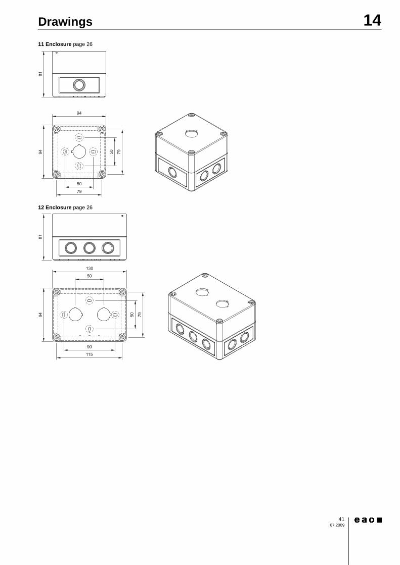
Enclosure
Dimension Typ-Nr. Tech
nica
l dra
win
g
e
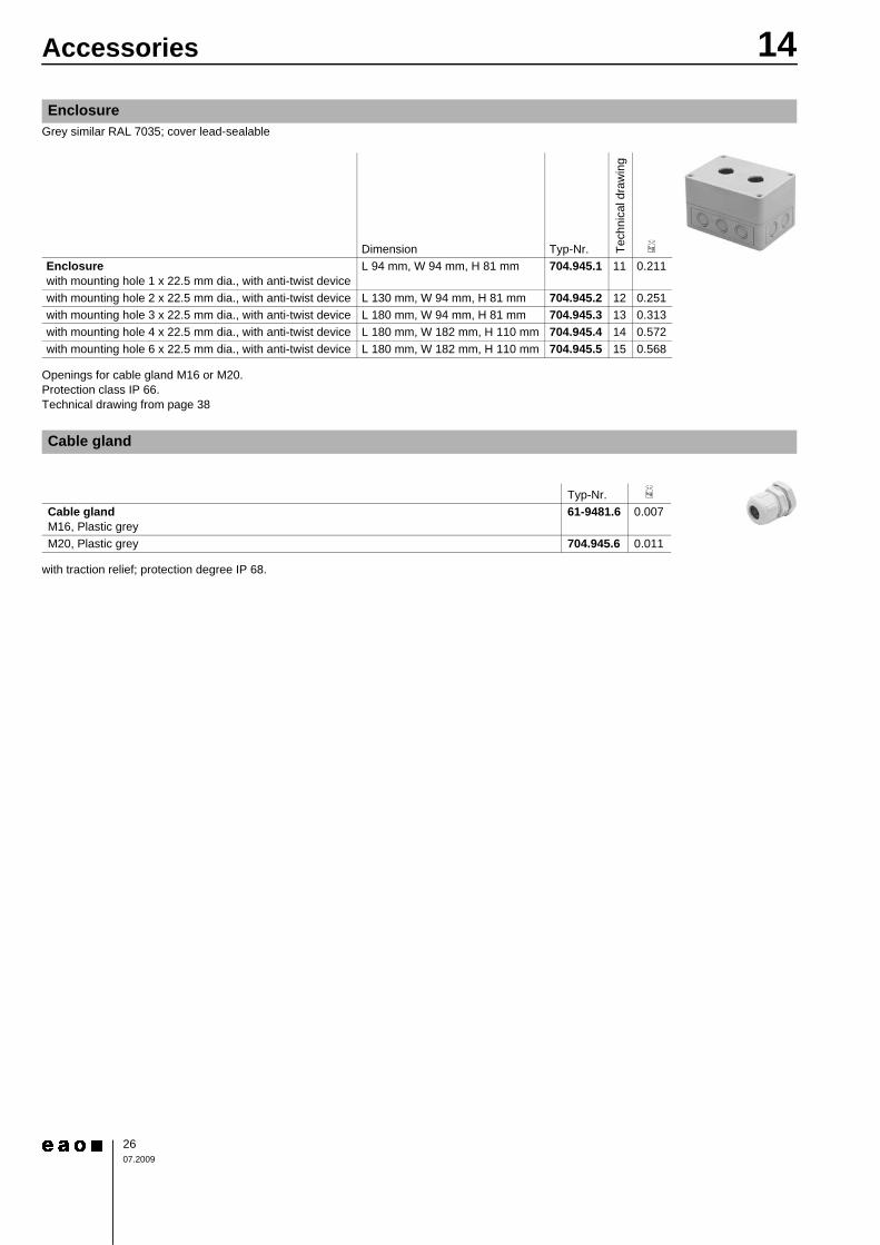
Enclosure with mounting hole 1 x 22.5 mm dia., with anti-twist device
L 94 mm, W 94 mm, H 81 mm 704.945.1 11 0.211
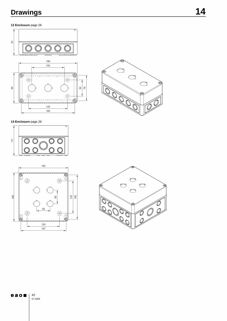
with mounting hole 2 x 22.5 mm dia., with anti-twist device L 130 mm, W 94 mm, H 81 mm 704.945.2 12 0.251with mounting hole 3 x 22.5 mm dia., with anti-twist device L 180 mm, W 94 mm, H 81 mm 704.945.3 13 0.313with mounting hole 4 x 22.5 mm dia., with anti-twist device L 180 mm, W 182 mm, H 110 mm 704.945.4 14 0.572with mounting hole 6 x 22.5 mm dia., with anti-twist device L 180 mm, W 182 mm, H 110 mm 704.945.5 15 0.568
Cable gland
Typ-Nr. e
Cable gland M16, Plastic grey
61-9481.6 0.007
M20, Plastic grey 704.945.6 0.011
2707.2009
14Technical Data
Switching systemSelf-cleaning, double-break, snap action switching system (with contact gap 2 x 0.5 mm).1 normally closed or 1 normally open contact per element.Snap-action switching elements with soldering terminals at the sides: up to 4 switching element can be on a pushbutton (max. 4 normally closed and 4 normally open contacts).Snap-action switching element with axial plug-in terminals 2.8 mm stackable, only 1 switching element can be on a pushbutton.
Material
Material of contactGold plated silver
Switch housingPlug-in-/soldering terminal Diallylphthalate DAP, Polyamide 66, Polysulfone, heat-resistant and self-extinguishingSoldering terminal: PA 6.6 Ultramide
Actuator housingPolyamide
Mechanical characteristics
TerminalsSnap-action switching element with tinned soldering terminals at the sides:Max. wire diameter 2 wires à 1.2 mmmax. wire cross-section of stranded cable 1x 1 mm²
Snap-action switching element with axial plug-in terminals, which can also be used as soldering terminals: Plug-in terminal 2.8 x 0.5 mm
Soldering terminal:Max. wire diameter 2 wires of 1 mmMax. wire cross-section of stranded cable 2 x 0.75 mm² or 1 x 1.0 mm²
Actuating torqueMeasured at the key or lever of the keylock- or selector switch2.5 Ncm ... 5.5 Ncm, depending on the number of switching elements
Actuating forceMaintain 5 N ... 7.8 NMomentary 3.2 N ... 6 Ndepending on the number of switching elements
Actuating travel0
Rebound time≤5ms
Mechanical lifetime0
Electrical characteristics
StandardsThe devices comply with : EN IEC 61058-1
Rated voltage250 VAC/DC as per EN IEC 61058-1-15
Contact resistanceNew state ≤50 mΩ as per DIN IEC 60512-2-4
Electrostatic discharge (ESD)Keylock switch 15 kV
Rated current5 A
Conventional free air thermal current Ith5 AThe maximum current in continuous operation and at ambient temperature not exceeding the quoted maximum values.
Switch rating250 VAC, 5 A (cosφ 1)250 VAC, 3 A (cosφ 0,3)
Switch rating AC (cosφ 0,7)0
Switch rating DC (inductive) L:R = 30 ms0
Electric strength3000 VAC, 50 Hz, 1 min. between all terminals and earth, as per EN IEC 61058-1-15
Isolation resistance>7 MΩ between the opend contats at 500 VDC, as per EN IEC 61058-1-15 (reinforced insulation)
Protection classII
Environmental conditions
Storage temperature-40 °C ... +85 °C
Service temperature-25 °C ... +55 °CFor indicators and illuminated pushbuttons mounted as a block, make sure the heat can escape freely.
Protection degreeas per EN IEC 60529front side IP 67
Shock resistance(semi-sinusoidal)max. 150 m/s², pulse width 11 ms, 3-axis, as per EN IEC 60068-2-27
Vibration resistance(sinusoidal)max. 100 m/s² at 10 Hz ... 500 Hz, as per EN IEC 60068-2-6
Actuator with snap-action switching element
Illuminated pushbutton: 3 mmSwitch actuator 2 positions:Momentary action 1 x ca. 42° deflection momentary actionMaintained action 1 x ca. 90° deflection maintained action
Momentary action 2 million Cycles of operationMaintained action 1 million Cycles of operation
Voltage 125 VAC 250 VACCurrent 3 A 2 A
Voltage 24 VDC 60 VDC 110 VDC 220 VDCCurrent 2 A 0.7 A 0.2 A 0.1 A
2807.2009
14Technical DataClimate resistanceDamp heat state as per EN IEC 60068-2-30Damp heat cyclic as per EN IEC 60068-2-78
Approvals
ApprobationsCB (IEC 61058)CSAENEC (EN 61058)Germanischer LloydUL
Declaration of conformityCE
>
Switching systemThis low level switching element was designed for switching low powers in electronic circuits. The mechanism assures reliable switching of loads ranging from a few μA/μV up to 100 mA/42 VAC/DC.Single-break momentary contact, as normally open or normally closed with 4 independent points of contact. 2 momentary contacts per switching element; combination of normally open and normally closed is possible.Special features are the long life, extremely short rebound time and stable contact resistance.
Material
Material of contactGold plated
Switch housingPolysulfone, heat-resistant and self-extinguishing
Actuator housingPolyamide
Mechanical characteristics
TerminalsThe universal terminals permit these units to be mounted on printed circuit boards (PCB). These terminals can also be used as soldering or plug-in terminals.For these terminals we can also supply a plug-in base which, when soldered on to the board, enables the switch to be plugged in.Soldering terminal: Max. wire diameter 2 wires of 1 mmMax. wire cross-section of stranded cable 2 x 0.75 mm²Plug-in terminal: 2.0 x 0.5 mm.
Actuating torqueMeasured at the key or lever of the keylock- or selector switch2.5 Ncm ... 5.5 Ncm, depending on the number of switching elements
Actuating force3 ... 4 N, depending on the number of switching elements
Actuating travel0
Rebound timetypical <100 μs
Mechanical lifetimeMomentary action 5 million cycles of operationMaintained action 1 million cycles of operation
Electrical characteristics
Contact resistanceNew state ≤50 mΩ as per DIN IEC 60512-2-4
Electrostatic discharge (ESD)Keylock switch 15 kV
Switch rating10 μA, 100 μV to 100 mA at 42 VAC/VDC
Electric strength3000 VAC, 50 Hz, 1 min. between all terminals and earth, as per EN IEC 61058-1-15
Protection classII
Environmental conditions
Storage temperature-40 °C ... +85 °C
Service temperature-25 °C ... +55 °CFor indicators and illuminated pushbuttons mounted as a block, make sure the heat can escape freely.
Protection degreeas per EN IEC 60529front side IP 67
Shock resistance(semi-sinusoidal)max. 150 m/s², pulse width 11 ms, 3-axis, as per EN IEC 60068-2-27
>
Buzzer system
SystemPiezo disc
Material
Alarm buzzer casePolyamide
Front capPlastic PolyamideMetal Nickel-plated brass (sea-water proof)
Mechanical characteristics
TerminalsPlug-in terminal 2.8 x 0.5 mm
Electrical characteristics
Frequency (tone)approx. 2.8 kHz continuous tone only
Actuator with low level switching element
Illuminated pushbutton : 3 mmSwitch actuator 2 positions:Momentary action 1 x ca. 42° deflection momentary actionMaintained action 1 x ca. 90° deflection maintained action
Buzzer
2907.2009
14Technical DataSound pressure95 db (A) ±8 dB at a distance of 0.1 m
Operation Voltage/Current0
Environmental conditions
Storage temperature-40 °C ... +85 °C
Operating temperature-25 °C ... +55 °C
Protection degreeas per EN IEC 60529, frontsideIP 40, devices flush mountingIP 65, devices raised mounting
Approvals
Declaration of conformityCE
Operation Voltage 24 VDC ±10 %Operation Current ≤25 mA
14Typical Applications
3007.2009
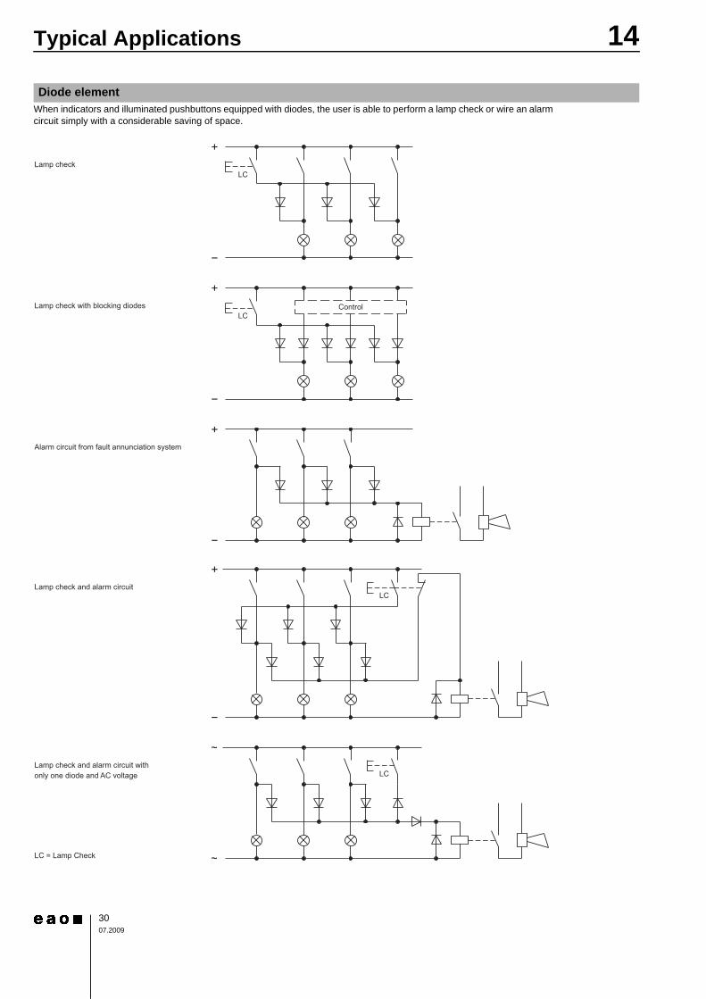
When indicators and illuminated pushbuttons equipped with diodes, the user is able to perform a lamp check or wire an alarm circuit simply with a considerable saving of space.
0
Diode element
14Application guidelines
3107.2009
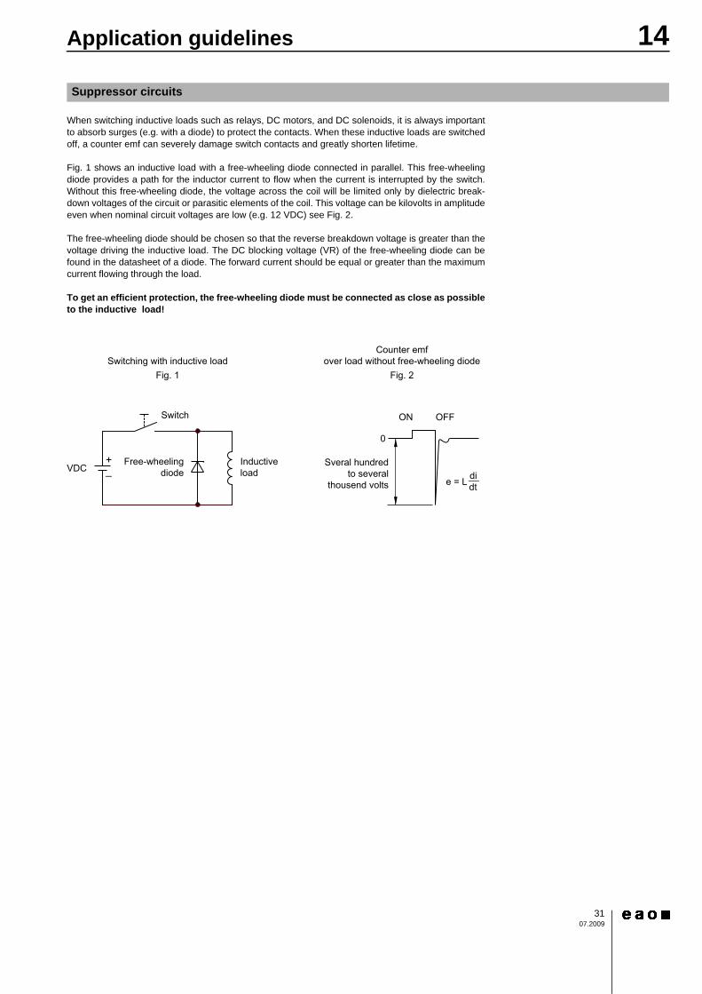
When switching inductive loads such as relays, DC motors, and DC solenoids, it is always importantto absorb surges (e.g. with a diode) to protect the contacts. When these inductive loads are switchedoff, a counter emf can severely damage switch contacts and greatly shorten lifetime.
Fig. 1 shows an inductive load with a free-wheeling diode connected in parallel. This free-wheelingdiode provides a path for the inductor current to flow when the current is interrupted by the switch.Without this free-wheeling diode, the voltage across the coil will be limited only by dielectric break-down voltages of the circuit or parasitic elements of the coil. This voltage can be kilovolts in amplitudeeven when nominal circuit voltages are low (e.g. 12 VDC) see Fig. 2.
The free-wheeling diode should be chosen so that the reverse breakdown voltage is greater than thevoltage driving the inductive load. The DC blocking voltage (VR) of the free-wheeling diode can befound in the datasheet of a diode. The forward current should be equal or greater than the maximumcurrent flowing through the load.
To get an efficient protection, the free-wheeling diode must be connected as close as possibleto the inductive load!
0
Suppressor circuits
Sveral hundredto several
thousend volts
ON OFF
0
e = L didt__
VDC
Switch
Free-wheelingdiode
Inductiveload
Counter emfover load without free-wheeling diode
Fig. 2Switching with inductive load
Fig. 1
+_
14Marking
3207.2009
0
>
All dimensions in mm0
0
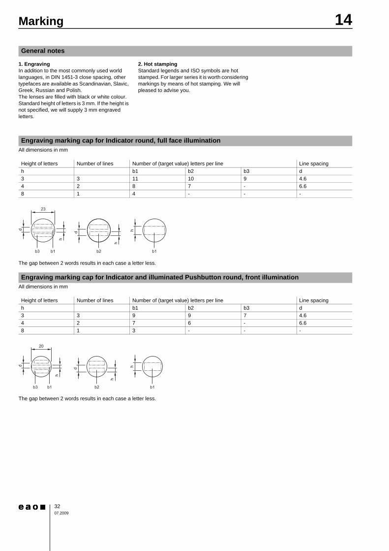
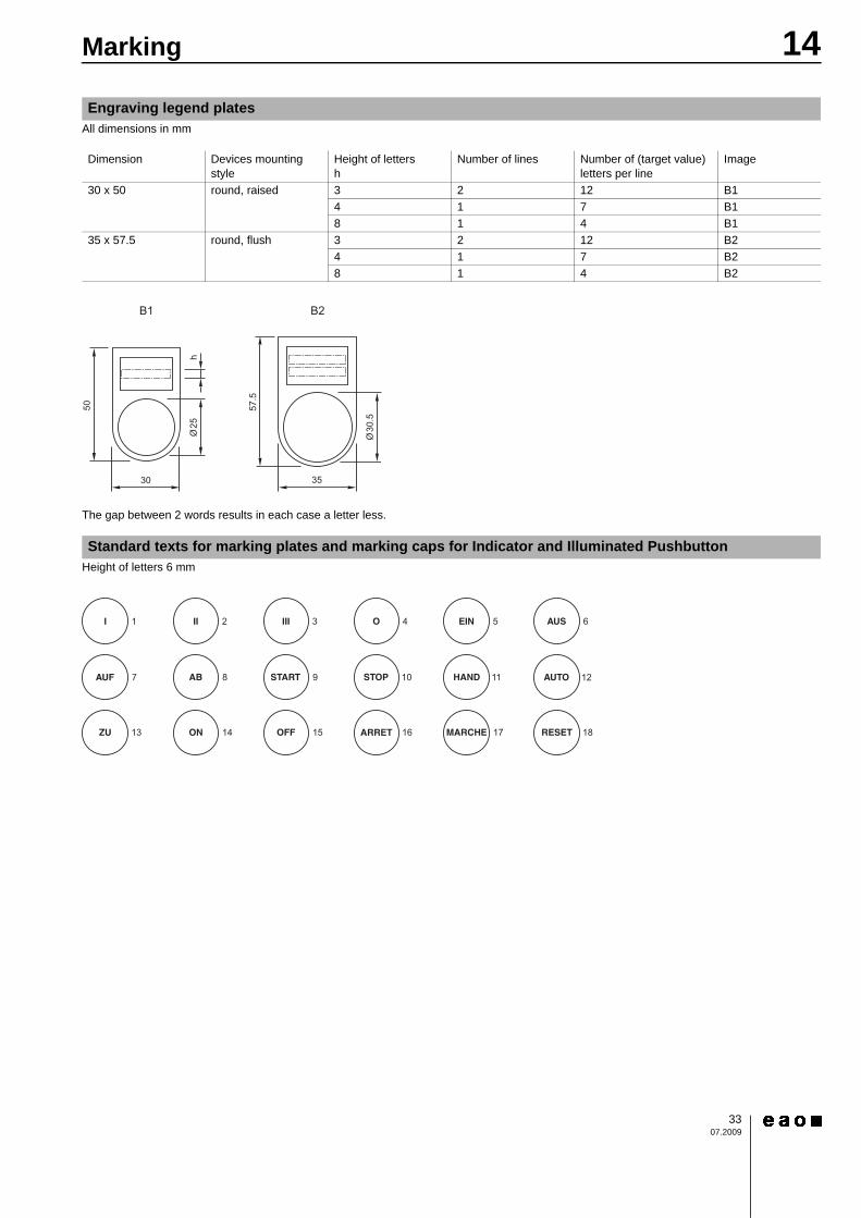
The gap between 2 words results in each case a letter less.>
All dimensions in mm0
0
The gap between 2 words results in each case a letter less.>
General notes
1. EngravingIn addition to the most commonly used world languages, in DIN 1451-3 close spacing, other typefaces are available as Scandinavian, Slavic, Greek, Russian and Polish.The lenses are filled with black or white colour.Standard height of letters is 3 mm. If the height is not specified, we will supply 3 mm engraved letters.
2. Hot stampingStandard legends and ISO symbols are hot stamped. For larger series it is worth considering markings by means of hot stamping. We will pleased to advise you.
Engraving marking cap for Indicator round, full face illumination
Height of letters Number of lines Number of (target value) letters per line Line spacingh b1 b2 b3 d3 3 11 10 9 4.64 2 8 7 - 6.68 1 4 - - -
Engraving marking cap for Indicator and illuminated Pushbutton round, front illumination
Height of letters Number of lines Number of (target value) letters per line Line spacingh b1 b2 b3 d3 3 9 9 7 4.64 2 7 6 - 6.68 1 3 - - -
14Marking
3307.2009
All dimensions in mm0
0
The gap between 2 words results in each case a letter less.>
Height of letters 6 mm0
Engraving legend plates
Dimension Devices mounting style
Height of lettersh
Number of lines Number of (target value) letters per line
Image
30 x 50 round, raised 3 2 12 B14 1 7 B18 1 4 B1
35 x 57.5 round, flush 3 2 12 B24 1 7 B28 1 4 B2
Standard texts for marking plates and marking caps for Indicator and Illuminated Pushbutton
B2B1
50
h
30
57.5
35
Ø25
Ø30
.5
14Marking
3407.2009
>
0
Continuation see next page>
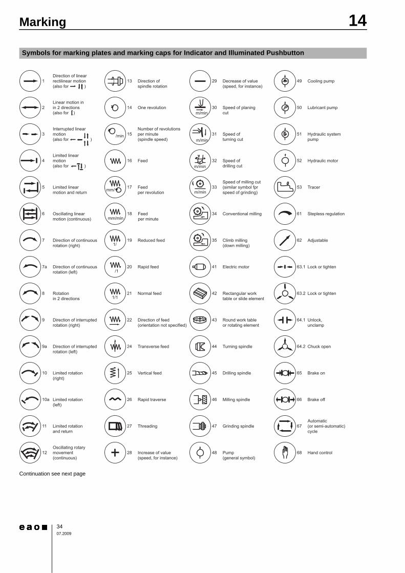
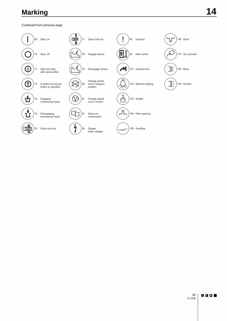
Symbols for marking plates and marking caps for Indicator and Illuminated Pushbutton
14Marking
3507.2009
Continued from previous page0
14Drawings
3607.2009
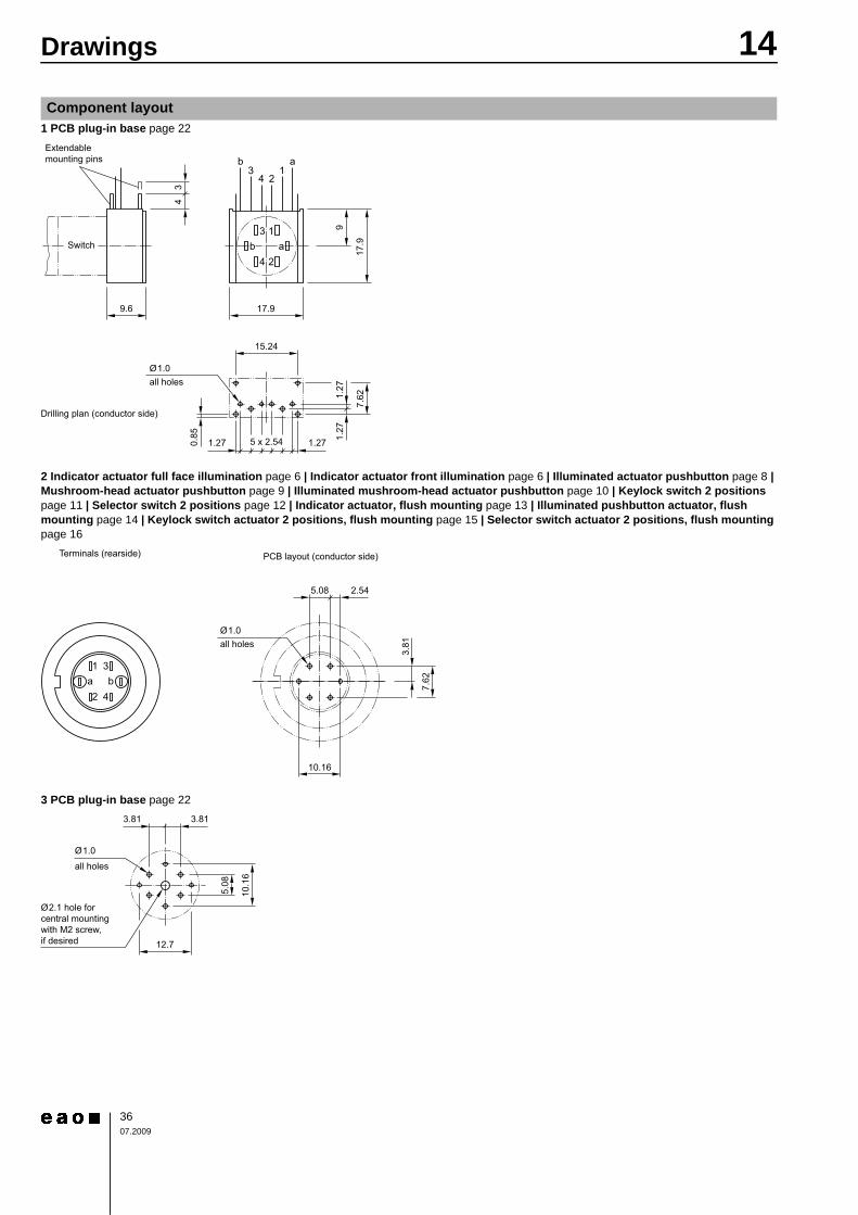
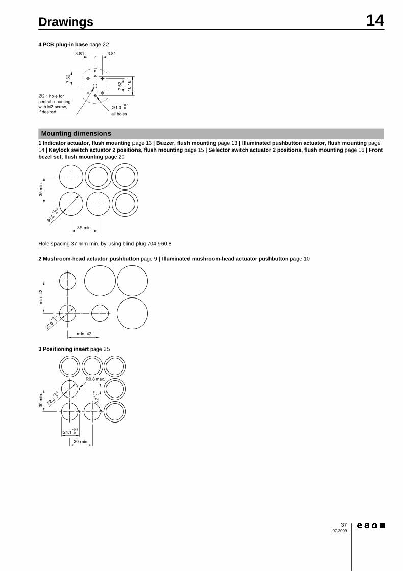
1 PCB plug-in base page 22
2 Indicator actuator full face illumination page 6 | Indicator actuator front illumination page 6 | Illuminated actuator pushbutton page 8 | Mushroom-head actuator pushbutton page 9 | Illuminated mushroom-head actuator pushbutton page 10 | Keylock switch 2 positions page 11 | Selector switch 2 positions page 12 | Indicator actuator, flush mounting page 13 | Illuminated pushbutton actuator, flush mounting page 14 | Keylock switch actuator 2 positions, flush mounting page 15 | Selector switch actuator 2 positions, flush mounting page 16
3 PCB plug-in base page 22
Component layout
3
4 2
1b
b3
4 21
a
a
all holes
Switch
Extendablemounting pins
Drilling plan (conductor side)
15.24
17.99.6
17.9
7.621.
271.
27
0.85
5 x 2.541.27 1.27
Ø1.0
9
34
PCB layout (conductor side)Terminals (rearside)
Ø1.0all holes
1
2 4
3a b
10.16
5.08 2.54
7.62
3.81
Ø2.1 hole forcentral mountingwith M2 screw,if desired
all holes
Ø1.0
5.08
10.1
6
12.7
3.813.81
14Drawings
3707.2009
4 PCB plug-in base page 22
1 Indicator actuator, flush mounting page 13 | Buzzer, flush mounting page 13 | Illuminated pushbutton actuator, flush mounting page 14 | Keylock switch actuator 2 positions, flush mounting page 15 | Selector switch actuator 2 positions, flush mounting page 16 | Front bezel set, flush mounting page 20
Hole spacing 37 mm min. by using blind plug 704.960.8
2 Mushroom-head actuator pushbutton page 9 | Illuminated mushroom-head actuator pushbutton page 10
3 Positioning insert page 25
Mounting dimensions
Ø2.1 hole for central mountingwith M2 screw,if desired all holes
Ø1.0+0.1 0
3.813.81
7.62
10.1
67.62
35 min.
35 m
in.
30.5+0.3
0
min
. 42
min. 42
+0.5
0
22.5
R0.8 max.
+0.4 0
30 m
in.
30 min.
24.1
3.2+
0.2
0+0.4
0
22.3
14Drawings
3807.2009
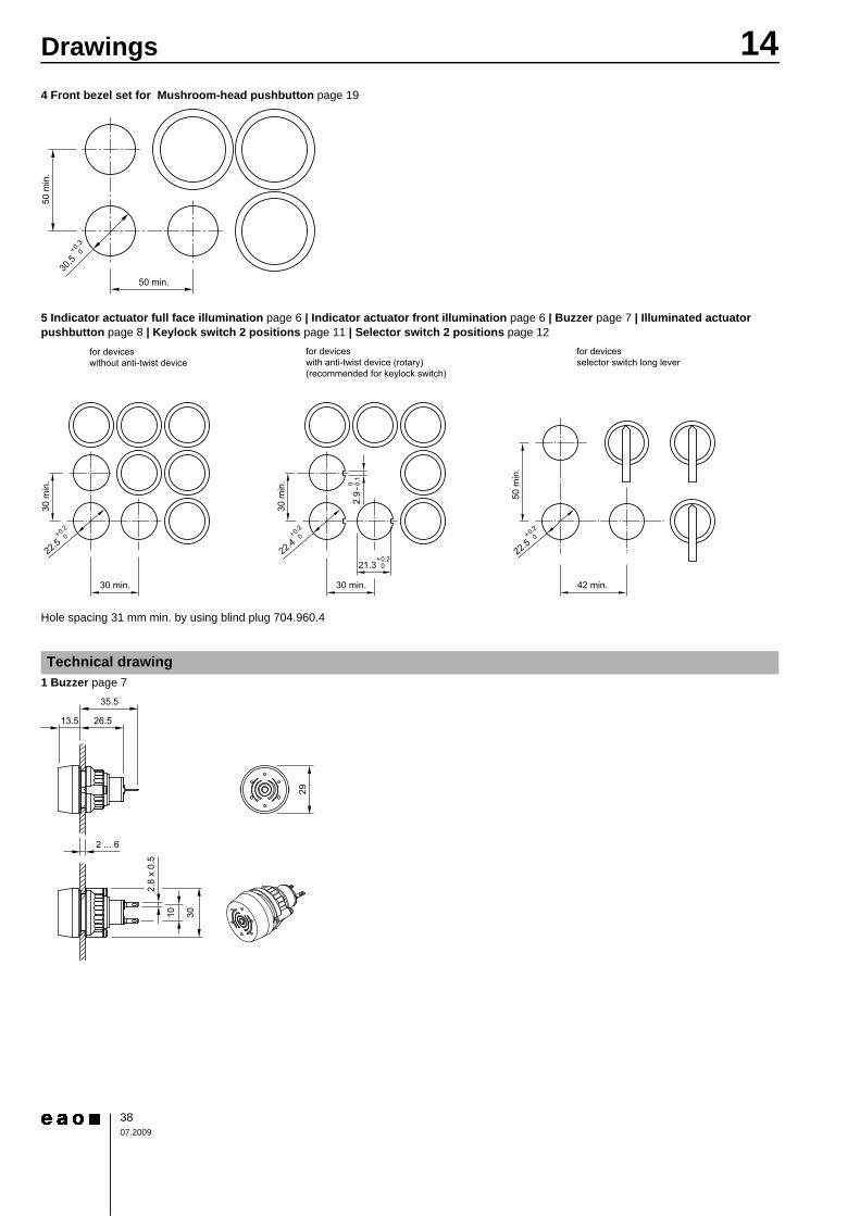
4 Front bezel set for Mushroom-head pushbutton page 19
5 Indicator actuator full face illumination page 6 | Indicator actuator front illumination page 6 | Buzzer page 7 | Illuminated actuator pushbutton page 8 | Keylock switch 2 positions page 11 | Selector switch 2 positions page 12
Hole spacing 31 mm min. by using blind plug 704.960.4
1 Buzzer page 7
Technical drawing
50 min.
50 m
in.
30.5+0.3
0
+0.2 0
30 m
in.
30 m
in.
50 m
in.
30 min.30 min. 42 min.
21.3
0 -0.1
2.9
+0.2
0
22.4+0.2
0
22.5+0.2
0
22.5
for devicesselector switch long lever
for deviceswith anti-twist device (rotary)(recommended for keylock switch)
for deviceswithout anti-twist device
2 ... 6
13.5 26.5
35.5
29
2.8
x 0.
5
3010
14Drawings
3907.2009
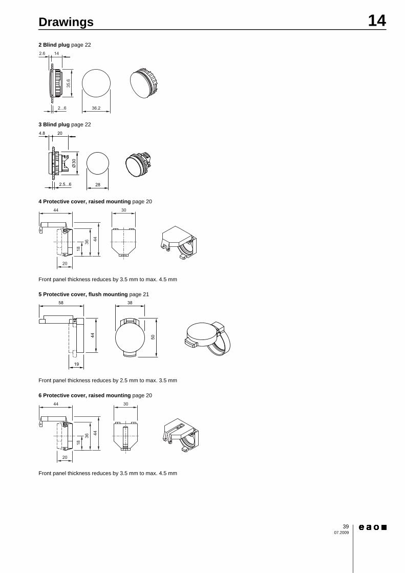
2 Blind plug page 22
3 Blind plug page 22
4 Protective cover, raised mounting page 20
Front panel thickness reduces by 3.5 mm to max. 4.5 mm
5 Protective cover, flush mounting page 21
Front panel thickness reduces by 2.5 mm to max. 3.5 mm
6 Protective cover, raised mounting page 20
Front panel thickness reduces by 3.5 mm to max. 4.5 mm
2.5...6 28
4.8 20
Ø30
14Drawings
4007.2009
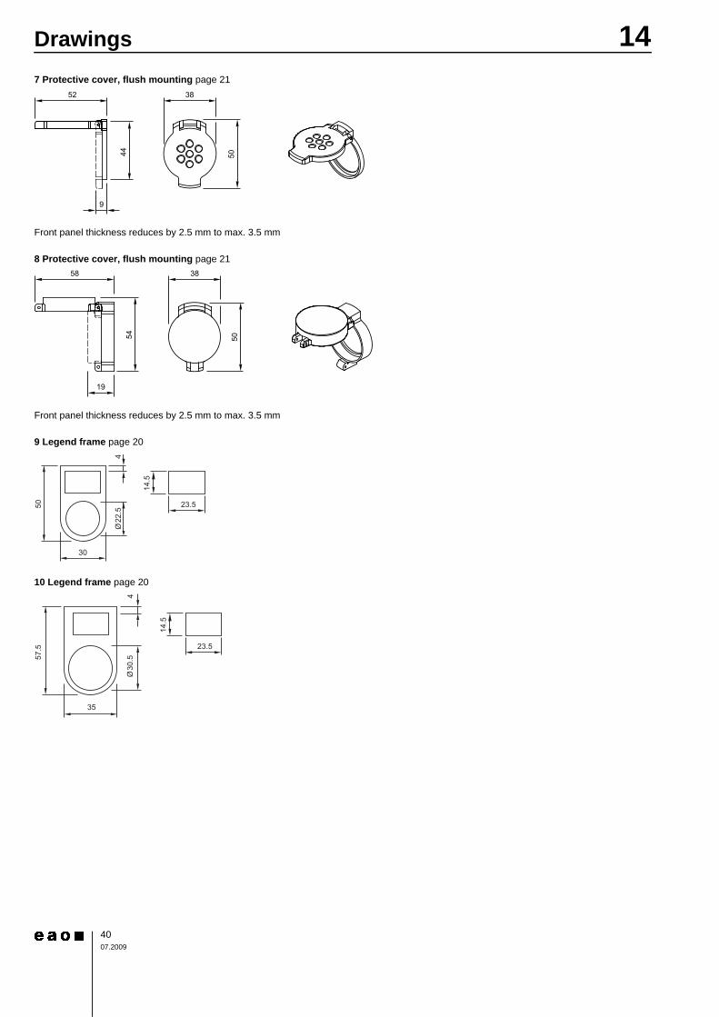
7 Protective cover, flush mounting page 21
Front panel thickness reduces by 2.5 mm to max. 3.5 mm
8 Protective cover, flush mounting page 21
Front panel thickness reduces by 2.5 mm to max. 3.5 mm
9 Legend frame page 20
10 Legend frame page 20
14.5
50
30
23.5
4Ø
22.5
14.5
57.5
35
23.5
4Ø
30.5
14Drawings
4107.2009
11 Enclosure page 26
12 Enclosure page 26
94
9481
50
50
79
79
8194 79
130
50
90
115
50
14Drawings
4207.2009
13 Enclosure page 26
14 Enclosure page 26
180
100
50
120
165
799481
111
180
120
120
182
165
167
50
50
14Drawings
4307.2009
15 Enclosure page 26
16 Buzzer, flush mounting page 13
111
182
180
50 50
50
120
120
167
165
2 ... 6
2 37.5
46.5
35
2.8
x 0.
5
3010
14Drawings
4407.2009
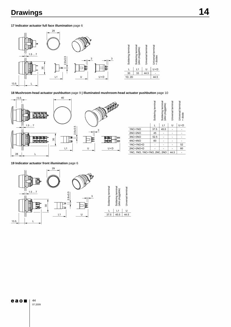
17 Indicator actuator full face illumination page 6
18 Mushroom-head actuator pushbutton page 9 | Illuminated mushroom-head actuator pushbutton page 10
19 Indicator actuator front illumination page 6
L L1 U U+D30 33 44.5 -
44.51D, 2D
Sol
derin
g te
rmin
al
Uni
vers
al te
rmin
al
Sol
derin
g te
rmin
al(a
lso
plug
gabl
e)
Uni
vers
al te
rmin
al+
diod
es
29
1.5 ... 7
30
L13.5
L1 U
3
U+D
3
2.8
x0.5
Sol
derin
g te
rmin
al
Uni
vers
al te
rmin
al
Uni
vers
al te
rmin
al+
diod
e
Sol
derin
g te
rmin
al(a
lso
plug
gabl
e)
U+DL1L U1NC+1NO2NC+2NO3NC+3NO4NC+4NO1NC+1NO+D2NC+2NO+D1NC, 1NO, 1NC+1NO, 2NC, 2NO 44.5
37.545
52.560
45.5---
5260-
--
--
----
----
--L1
L
U+DU
28
13.5
3
2.8
x0.5
40
1.5 ... 7
30
L L1 U37.5 45.5 44.5
Sol
derin
g te
rmin
al
Unv
ersa
l ter
min
al
Sol
derin
g te
rmin
al(a
lso
plug
gabl
e)
29
1.5 ... 7
30
L13.5
L1 U
3
2.8
x0.5
14Drawings
4507.2009
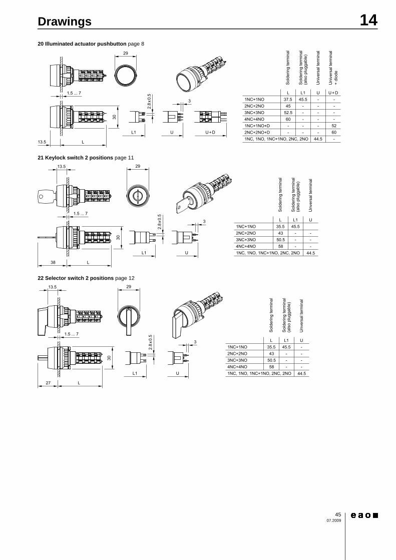
20 Illuminated actuator pushbutton page 8
21 Keylock switch 2 positions page 11
22 Selector switch 2 positions page 12
L U+DL1 U1NC+1NO2NC+2NO3NC+3NO4NC+4NO1NC+1NO+D2NC+2NO+D
37.545
52.560
45.5---
5260
--
--
----
----
--
1NC, 1NO, 1NC+1NO, 2NC, 2NO -44.5
Sol
derin
g te
rmin
al
Uni
vers
al te
rmin
al
Uni
vers
al te
rmin
al+
diod
e
Sol
derin
g te
rmin
al(a
lso
plug
gabl
e)
L1
L
U+DU
13.5
3
2.8
x0.5
29
1.5 ... 7
30
Sol
derin
g te
rmin
al
Unv
ersa
l ter
min
al
Sol
derin
g te
rmin
al(a
lso
plug
gabl
e)
L1L U1NC+1NO2NC+2NO3NC+3NO4NC+4NO
35.543
50.558
45.5---
---
1NC, 1NO, 1NC+1NO, 2NC, 2NO 44.5L1
L
U
38
13.5
3
2.8
x0.5
29
1.5 ... 7
30
Sol
derin
g te
rmin
al
Unv
ersa
l ter
min
al
Sol
derin
g te
rmin
al(a
lso
plug
gabl
e)
L1L U1NC+1NO2NC+2NO3NC+3NO4NC+4NO
35.543
50.558
45.5 ----
---
1NC, 1NO, 1NC+1NO, 2NC, 2NO 44.5L1
L
U
27
13.5
3
2.8
x0.5
29
1.5 ... 7
30
14Drawings
4607.2009
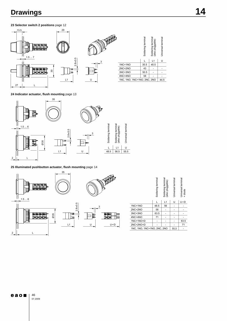
23 Selector switch 2 positions page 12
24 Indicator actuator, flush mounting page 13
25 Illuminated pushbutton actuator, flush mounting page 14
Sol
derin
g te
rmin
al
Uni
vers
al te
rmin
al
Sol
derin
g te
rmin
al(a
lso
plug
gabl
e)
L1L U1NC+1NO2NC+2NO3NC+3NO4NC+4NO
35.543
50.558
45.5---
---
1NC, 1NO, 1NC+1NO, 2NC, 2NO 44.5L1
L
U
27
13.5
3
2.8
x0.5
29
1.5 ... 7
30
L L1 U48.5 56.5 55.5
Sol
derin
g te
rmin
al
Uni
vers
al te
rmin
al
Sol
derin
g te
rmin
al(a
lso
plug
gabl
e)
35
1.5 ... 6
Ø35
L2
L1 U
3
2.8
x0.5
Sol
derin
g te
rmin
al
Uni
vers
al te
rmin
al
Uni
vers
al te
rmin
al+
diod
e
Sol
derin
g te
rmin
al(a
lso
plug
gabl
e)
U+DL1L U1NC+1NO2NC+2NO3NC+3NO4NC+4NO1NC+1NO+D2NC+2NO+D1NC, 1NO, 1NC+1NO, 2NC, 2NO 55,5
48.556
63.571
56---
63.571-
--
--
----
----
--L1
L
U+DU
2
2.8
x0.5
35
1.5 ... 6
3
Ø35
14Drawings
4707.2009
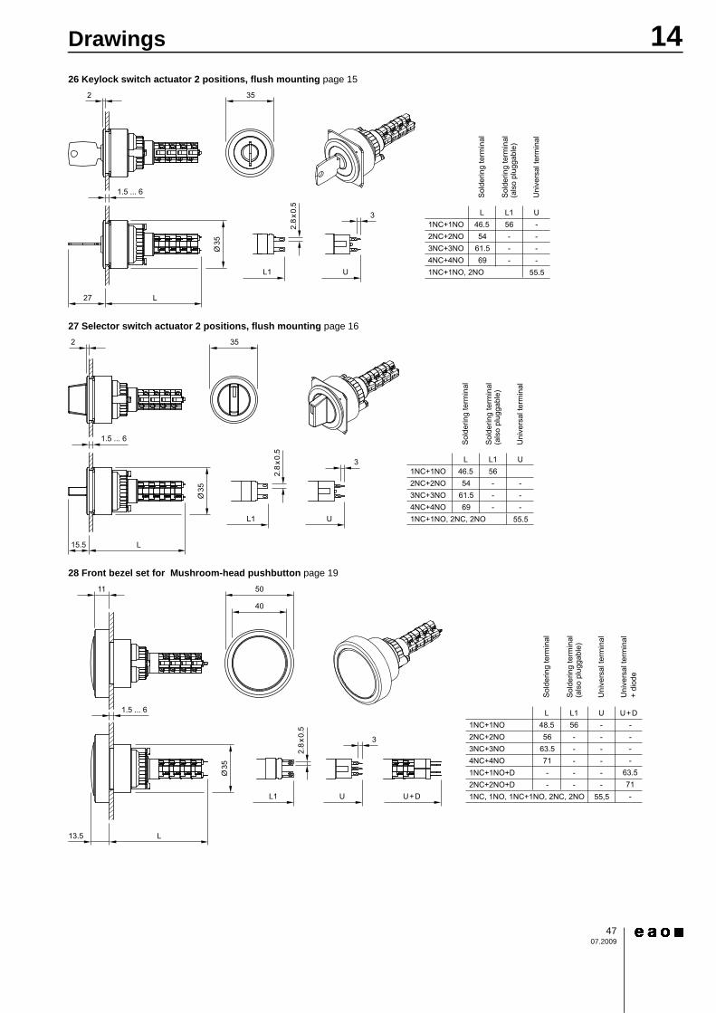
26 Keylock switch actuator 2 positions, flush mounting page 15
27 Selector switch actuator 2 positions, flush mounting page 16
28 Front bezel set for Mushroom-head pushbutton page 19
Sol
derin
g te
rmin
al
Uni
vers
al te
rmin
al
Sol
derin
g te
rmin
al(a
lso
plug
gabl
e)
L1L U1NC+1NO2NC+2NO3NC+3NO4NC+4NO
46.554
61.569
56 ----
1NC+1NO, 2NO 55.5
---
L1
L
U
272.
8x0
.5
Ø35
35
1.5 ... 6
3
2
Sol
derin
g te
rmin
al
Uni
vers
al te
rmin
al
Sol
derin
g te
rmin
al(a
lso
plug
gabl
e)
L1L U1NC+1NO2NC+2NO3NC+3NO4NC+4NO
46.554
61.569
56---
1NC+1NO, 2NC, 2NO 55.5
---
L1
L
U
15.5
2.8
x0.5
Ø35
35
1.5 ... 6
3
2
Sol
derin
g te
rmin
al
Uni
vers
al te
rmin
al
Uni
vers
al te
rmin
al+
diod
e
Sol
derin
g te
rmin
al(a
lso
plug
gabl
e)
U+DL1L U1NC+1NO2NC+2NO3NC+3NO4NC+4NO1NC+1NO+D2NC+2NO+D1NC, 1NO, 1NC+1NO, 2NC, 2NO 55,5
48.556
63.571
56---
63.571-
--
--
----
----
--
L1
L
U+DU
13.5
11
3
2.8
x0.5
50
40
1.5 ... 6
Ø35
14Drawings
4807.2009
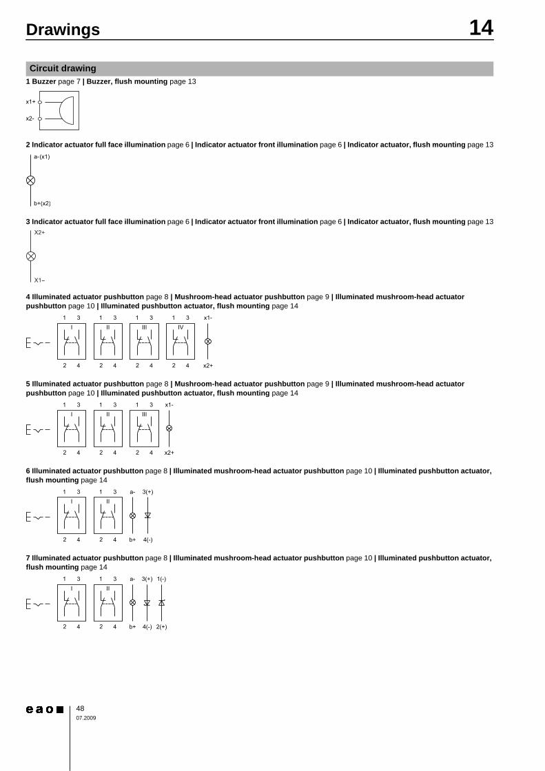
1 Buzzer page 7 | Buzzer, flush mounting page 13
2 Indicator actuator full face illumination page 6 | Indicator actuator front illumination page 6 | Indicator actuator, flush mounting page 13
3 Indicator actuator full face illumination page 6 | Indicator actuator front illumination page 6 | Indicator actuator, flush mounting page 13
4 Illuminated actuator pushbutton page 8 | Mushroom-head actuator pushbutton page 9 | Illuminated mushroom-head actuator pushbutton page 10 | Illuminated pushbutton actuator, flush mounting page 14
5 Illuminated actuator pushbutton page 8 | Mushroom-head actuator pushbutton page 9 | Illuminated mushroom-head actuator pushbutton page 10 | Illuminated pushbutton actuator, flush mounting page 14
6 Illuminated actuator pushbutton page 8 | Illuminated mushroom-head actuator pushbutton page 10 | Illuminated pushbutton actuator, flush mounting page 14
7 Illuminated actuator pushbutton page 8 | Illuminated mushroom-head actuator pushbutton page 10 | Illuminated pushbutton actuator, flush mounting page 14
Circuit drawing
x2-
x1+
b+(x2)
a-(x1)
31 x1-
2 4 x2+
I31
2 4
II31
2 4
III31
2 4
IV
31 x1-
2 4 x2+
I31
2 4
II31
2 4
III
31 a-
2 4 b+
3(+)
4(-)
I31
2 4
II
31 a-
2 4 b+
3(+)
4(-)
I31
2 4
II1(-)
2(+)
14Drawings
4907.2009
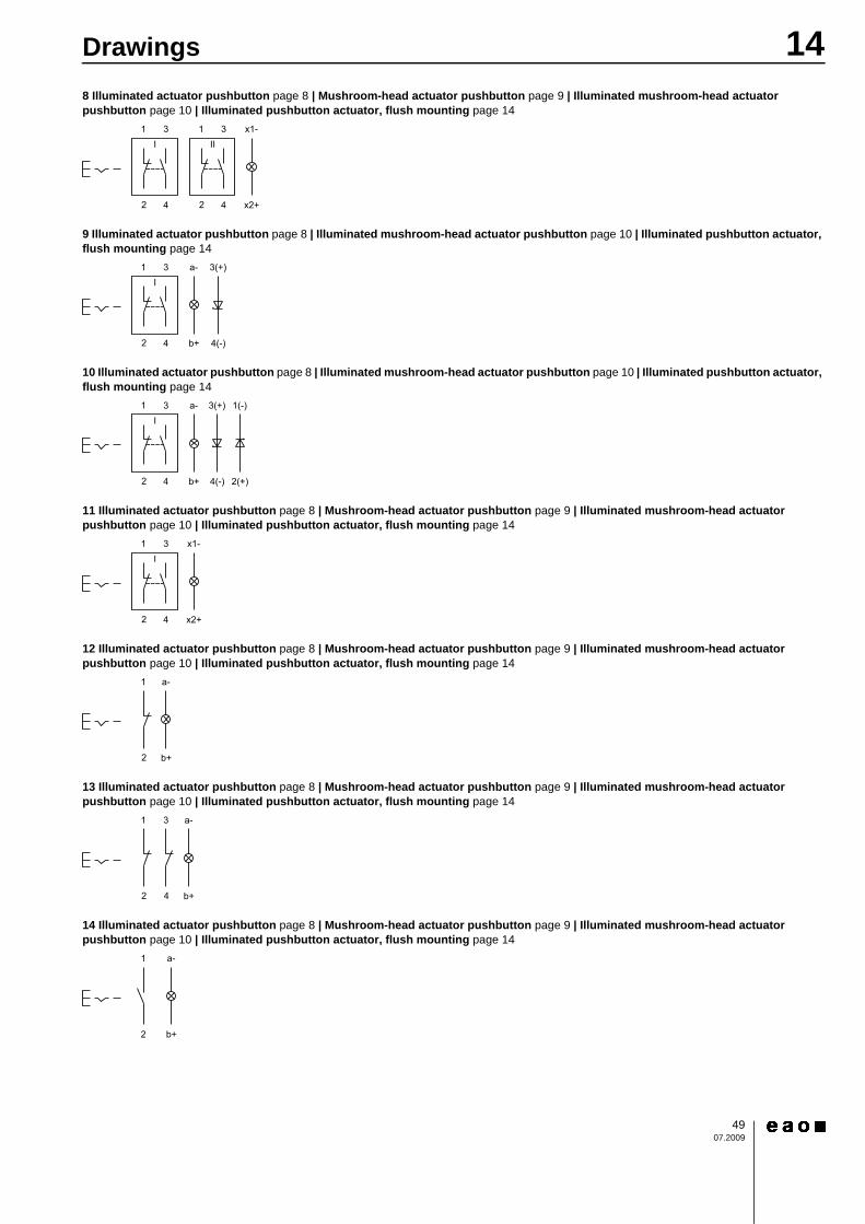
8 Illuminated actuator pushbutton page 8 | Mushroom-head actuator pushbutton page 9 | Illuminated mushroom-head actuator pushbutton page 10 | Illuminated pushbutton actuator, flush mounting page 14
9 Illuminated actuator pushbutton page 8 | Illuminated mushroom-head actuator pushbutton page 10 | Illuminated pushbutton actuator, flush mounting page 14
10 Illuminated actuator pushbutton page 8 | Illuminated mushroom-head actuator pushbutton page 10 | Illuminated pushbutton actuator, flush mounting page 14
11 Illuminated actuator pushbutton page 8 | Mushroom-head actuator pushbutton page 9 | Illuminated mushroom-head actuator pushbutton page 10 | Illuminated pushbutton actuator, flush mounting page 14
12 Illuminated actuator pushbutton page 8 | Mushroom-head actuator pushbutton page 9 | Illuminated mushroom-head actuator pushbutton page 10 | Illuminated pushbutton actuator, flush mounting page 14
13 Illuminated actuator pushbutton page 8 | Mushroom-head actuator pushbutton page 9 | Illuminated mushroom-head actuator pushbutton page 10 | Illuminated pushbutton actuator, flush mounting page 14
14 Illuminated actuator pushbutton page 8 | Mushroom-head actuator pushbutton page 9 | Illuminated mushroom-head actuator pushbutton page 10 | Illuminated pushbutton actuator, flush mounting page 14
31 x1-
2 4 x2+
I31
2 4
II
31 a-
2 4 b+
3(+)
4(-)
I
31 a-
2 4 b+
3(+)
4(-)
I1(-)
2(+)
31 x1-
2 4 x2+
I
1 a-
2 b+
1 a-
2
3
4 b+
1 a-
2 b+
14Drawings
5007.2009
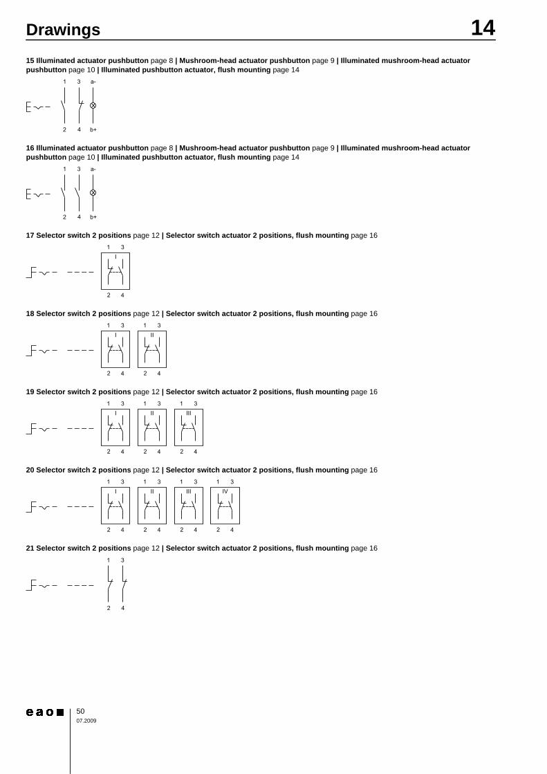
15 Illuminated actuator pushbutton page 8 | Mushroom-head actuator pushbutton page 9 | Illuminated mushroom-head actuator pushbutton page 10 | Illuminated pushbutton actuator, flush mounting page 14
16 Illuminated actuator pushbutton page 8 | Mushroom-head actuator pushbutton page 9 | Illuminated mushroom-head actuator pushbutton page 10 | Illuminated pushbutton actuator, flush mounting page 14
17 Selector switch 2 positions page 12 | Selector switch actuator 2 positions, flush mounting page 16
18 Selector switch 2 positions page 12 | Selector switch actuator 2 positions, flush mounting page 16
19 Selector switch 2 positions page 12 | Selector switch actuator 2 positions, flush mounting page 16
20 Selector switch 2 positions page 12 | Selector switch actuator 2 positions, flush mounting page 16
21 Selector switch 2 positions page 12 | Selector switch actuator 2 positions, flush mounting page 16
1 3 a-
42 b+
1 3 a-
42 b+
31
2 4
I
31
2 4
I31
2 4
II
31
2 4
I31
2 4
II31
2 4
III
31
2 4
I31
2 4
II31
2 4
III31
2 4
IV
1
2
3
4
14Drawings
5107.2009
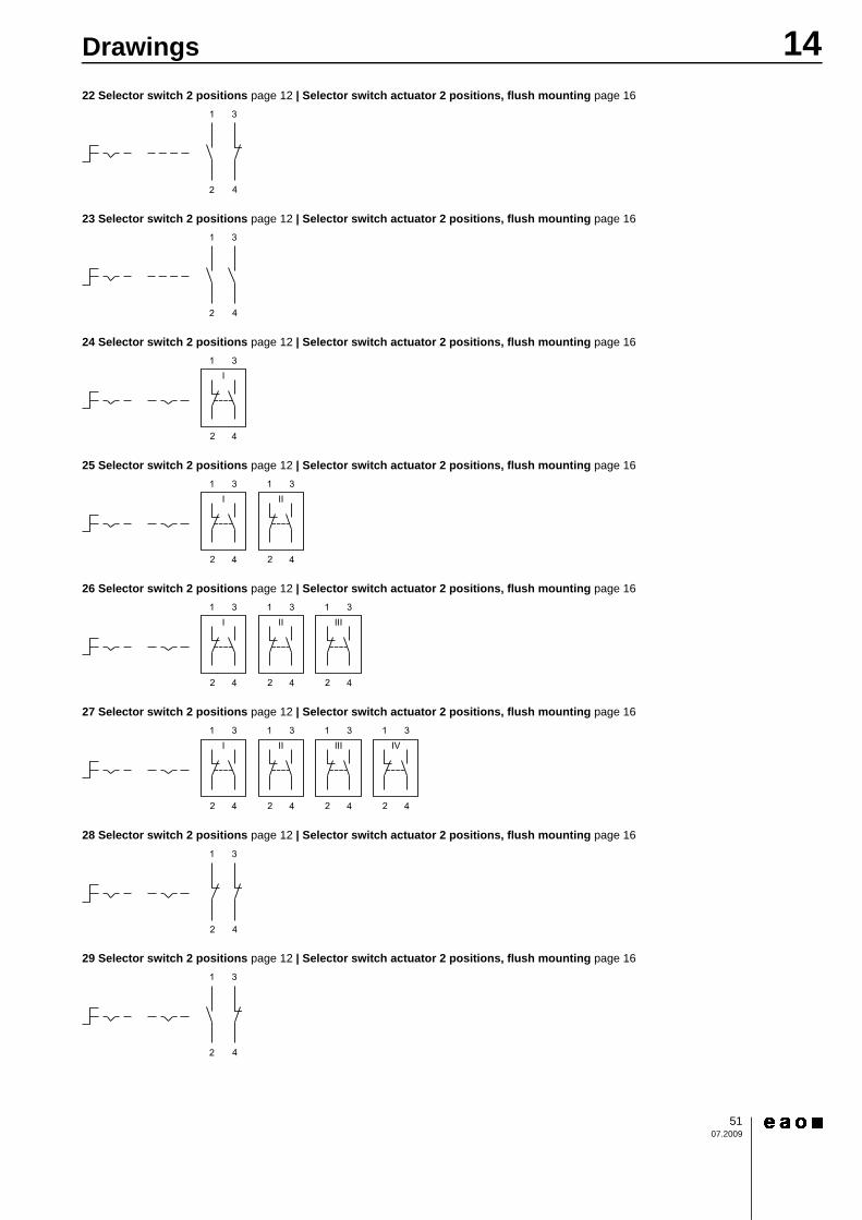
22 Selector switch 2 positions page 12 | Selector switch actuator 2 positions, flush mounting page 16
23 Selector switch 2 positions page 12 | Selector switch actuator 2 positions, flush mounting page 16
24 Selector switch 2 positions page 12 | Selector switch actuator 2 positions, flush mounting page 16
25 Selector switch 2 positions page 12 | Selector switch actuator 2 positions, flush mounting page 16
26 Selector switch 2 positions page 12 | Selector switch actuator 2 positions, flush mounting page 16
27 Selector switch 2 positions page 12 | Selector switch actuator 2 positions, flush mounting page 16
28 Selector switch 2 positions page 12 | Selector switch actuator 2 positions, flush mounting page 16
29 Selector switch 2 positions page 12 | Selector switch actuator 2 positions, flush mounting page 16
1 3
42
1 3
42
31
2 4
I
31
2 4
I31
2 4
II
31
2 4
I31
2 4
II31
2 4
III
31
2 4
I31
2 4
II31
2 4
III31
2 4
IV
1
2
3
4
1 3
42
14Drawings
5207.2009
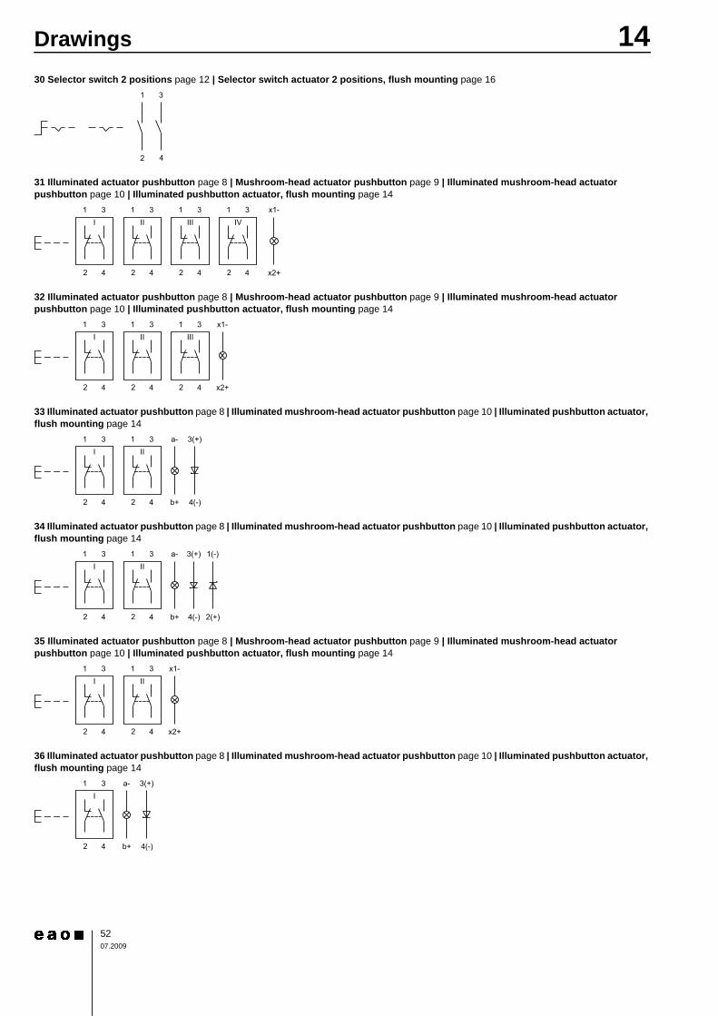
30 Selector switch 2 positions page 12 | Selector switch actuator 2 positions, flush mounting page 16
31 Illuminated actuator pushbutton page 8 | Mushroom-head actuator pushbutton page 9 | Illuminated mushroom-head actuator pushbutton page 10 | Illuminated pushbutton actuator, flush mounting page 14
32 Illuminated actuator pushbutton page 8 | Mushroom-head actuator pushbutton page 9 | Illuminated mushroom-head actuator pushbutton page 10 | Illuminated pushbutton actuator, flush mounting page 14
33 Illuminated actuator pushbutton page 8 | Illuminated mushroom-head actuator pushbutton page 10 | Illuminated pushbutton actuator, flush mounting page 14
34 Illuminated actuator pushbutton page 8 | Illuminated mushroom-head actuator pushbutton page 10 | Illuminated pushbutton actuator, flush mounting page 14
35 Illuminated actuator pushbutton page 8 | Mushroom-head actuator pushbutton page 9 | Illuminated mushroom-head actuator pushbutton page 10 | Illuminated pushbutton actuator, flush mounting page 14
36 Illuminated actuator pushbutton page 8 | Illuminated mushroom-head actuator pushbutton page 10 | Illuminated pushbutton actuator, flush mounting page 14
1 3
42
31 x1-
2 4 x2+
I31
2 4
II31
2 4
III31
2 4
IV
31 x1-
2 4 x2+
I31
2 4
II31
2 4
III
31 a-
2 4 b+
3(+)
4(-)
I31
2 4
II
31 a-
2 4 b+
3(+)
4(-)
I31
2 4
II1(-)
2(+)
31 x1-
2 4 x2+
I31
2 4
II
31 a-
2 4 b+
3(+)
4(-)
I
1 4Drawings
5307.2009
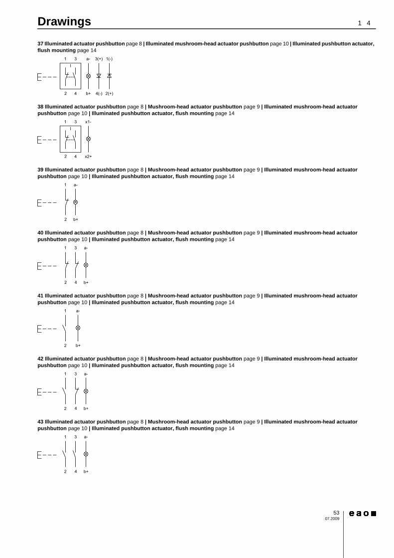
37 Illuminated actuator pushbutton page 8 | Illuminated mushroom-head actuator pushbutton page 10 | Illuminated pushbutton actuator, flush mounting page 14
38 Illuminated actuator pushbutton page 8 | Mushroom-head actuator pushbutton page 9 | Illuminated mushroom-head actuator pushbutton page 10 | Illuminated pushbutton actuator, flush mounting page 14
39 Illuminated actuator pushbutton page 8 | Mushroom-head actuator pushbutton page 9 | Illuminated mushroom-head actuator pushbutton page 10 | Illuminated pushbutton actuator, flush mounting page 14
40 Illuminated actuator pushbutton page 8 | Mushroom-head actuator pushbutton page 9 | Illuminated mushroom-head actuator pushbutton page 10 | Illuminated pushbutton actuator, flush mounting page 14
41 Illuminated actuator pushbutton page 8 | Mushroom-head actuator pushbutton page 9 | Illuminated mushroom-head actuator pushbutton page 10 | Illuminated pushbutton actuator, flush mounting page 14
42 Illuminated actuator pushbutton page 8 | Mushroom-head actuator pushbutton page 9 | Illuminated mushroom-head actuator pushbutton page 10 | Illuminated pushbutton actuator, flush mounting page 14
43 Illuminated actuator pushbutton page 8 | Mushroom-head actuator pushbutton page 9 | Illuminated mushroom-head actuator pushbutton page 10 | Illuminated pushbutton actuator, flush mounting page 14
31 a-
2 4 b+
3(+)
4(-)
I1(-)
2(+)
31 x1-
2 4 x2+
I
1 a-
2 b+
1 a-
2
3
4 b+
1 a-
2 b+
1 3 a-
42 b+
1 3 a-
42 b+
14Drawings
5407.2009
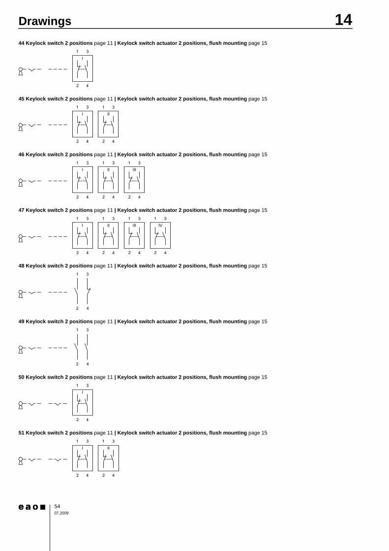
44 Keylock switch 2 positions page 11 | Keylock switch actuator 2 positions, flush mounting page 15
45 Keylock switch 2 positions page 11 | Keylock switch actuator 2 positions, flush mounting page 15
46 Keylock switch 2 positions page 11 | Keylock switch actuator 2 positions, flush mounting page 15
47 Keylock switch 2 positions page 11 | Keylock switch actuator 2 positions, flush mounting page 15
48 Keylock switch 2 positions page 11 | Keylock switch actuator 2 positions, flush mounting page 15
49 Keylock switch 2 positions page 11 | Keylock switch actuator 2 positions, flush mounting page 15
50 Keylock switch 2 positions page 11 | Keylock switch actuator 2 positions, flush mounting page 15
51 Keylock switch 2 positions page 11 | Keylock switch actuator 2 positions, flush mounting page 15
31
2 4
I
31
2 4
I31
2 4
II
31
2 4
I31
2 4
II31
2 4
III
31
2 4
I31
2 4
II31
2 4
III31
2 4
IV
1 3
42
1 3
42
31
2 4
I
31
2 4
I31
2 4
II
14Drawings
5507.2009
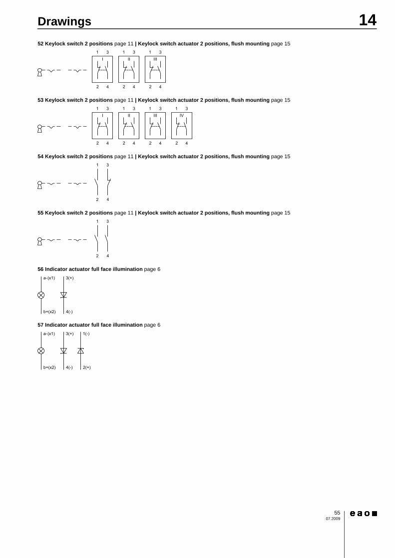
52 Keylock switch 2 positions page 11 | Keylock switch actuator 2 positions, flush mounting page 15
53 Keylock switch 2 positions page 11 | Keylock switch actuator 2 positions, flush mounting page 15
54 Keylock switch 2 positions page 11 | Keylock switch actuator 2 positions, flush mounting page 15
55 Keylock switch 2 positions page 11 | Keylock switch actuator 2 positions, flush mounting page 15
56 Indicator actuator full face illumination page 6
57 Indicator actuator full face illumination page 6
31
2 4
I31
2 4
II31
2 4
III
31
2 4
I31
2 4
II31
2 4
III31
2 4
IV
1 3
42
1 3
42
b+(x2) 4(-)
a-(x1) 3(+)
b+(x2) 4(-)
a-(x1) 3(+)
2(+)
1(-)
Index from Typ-Nr.
5608.2009
Typ-Nr. Page Typ-Nr. Page Typ-Nr. Page
01-928 ........................................2301-929 ........................................2302-906 ........................................2502-912.1 .....................................2402-912.2 .....................................2402-912.3 .....................................2402-912.4 .....................................2410-1106.1369 .............................2310-1109.1279 .............................2310-1109.1329 .............................2310-1112.1199 .............................2310-1112.1279 .............................2310-1113.1249 .............................2310-1114.1249 .............................2310-1116.1229 .............................2310-1119.1199 .............................2310-2106.3142 .............................2410-2106.3144 .............................2410-2106.3145 .............................2410-2106.3146 .............................2410-2106.3149 .............................2410-2109.1062 .............................2410-2109.1064 .............................2410-2109.1065 .............................2410-2109.1066 .............................2410-2109.1069 .............................2410-2112.1062 .............................2410-2112.1064 .............................2410-2112.1065 .............................2410-2112.1066 .............................2410-2112.1069 .............................2410-2113.1062 .............................2410-2113.1064 .............................2410-2113.1065 .............................2410-2113.1066 .............................2410-2113.1069 .............................2410-2119.1042 .............................2410-2119.1044 .............................2410-2119.1045 .............................2410-2119.1046 .............................2410-2119.1049 .............................2414-030.002 ...................................614-030.005 ...................................614-031.006 ...................................614-040.002 .................................1314-040.002 ...................................614-040.005 .................................1314-040.005 ...................................614-041.006 .................................1314-041.006 ...................................614-131.022 .................................1014-131.022 .................................1414-131.022 ...................................814-131.022 ...................................914-131.0252 ...............................1014-131.0252 ...............................1414-131.0252 .................................814-131.0252 .................................914-132.0252 ...............................1014-132.0252 ...............................1414-132.0252 .................................814-132.0252 .................................914-133.0252 ...............................10
14-133.0252 ...............................1414-133.0252 .................................814-133.0252 .................................914-134.0252 ...............................1014-134.0252 ...............................1414-134.0252 .................................814-134.0252 .................................914-135.022K ...............................1114-135.022K ...............................1514-135.025K2 .............................1114-135.025K2 .............................1514-136.025K2 .............................1114-136.025K2 .............................1514-137.025K2 .............................1114-137.025K2 .............................1514-138.025K2 .............................1114-138.025K2 .............................1514-141.022K ...............................1114-141.022K ...............................1514-141.025K2 .............................1114-141.025K2 .............................1514-142.025K2 .............................1114-142.025K2 .............................1514-143.025K2 .............................1114-143.025K2 .............................1514-144.025K2 .............................1114-144.025K2 .............................1514-235.022K ...............................1114-235.022K ...............................1514-235.025K2 .............................1114-235.025K2 .............................1514-236.025K2 .............................1114-236.025K2 .............................1514-237.025K2 .............................1114-237.025K2 .............................1514-238.025K2 .............................1114-238.025K2 .............................1514-271.022 .................................1014-271.022 .................................1414-271.022 ...................................814-271.022 ...................................914-271.0252 ...............................1014-271.0252 ...............................1414-271.0252 .................................814-271.0252 .................................914-272.0252 ...............................1014-272.0252 ...............................1414-272.0252 .................................814-272.0252 .................................914-273.0252 ...............................1014-273.0252 ...............................1414-273.0252 .................................814-273.0252 .................................914-274.0252 ...............................1014-274.0252 ...............................1414-274.0252 .................................814-274.0252 .................................914-335.022K ...............................1114-335.022K ...............................1514-335.025K2 .............................1114-335.025K2 .............................1514-336.025K2 .............................1114-336.025K2 .............................15
14-337.025K2 .............................1114-337.025K2 .............................1514-338.025K2 .............................1114-338.025K2 .............................1514-411.036K ...............................1114-411.036K ...............................1514-412.036K ...............................1114-412.036K ...............................1514-414.036K ...............................1114-414.036K ...............................1514-415.036K ...............................1114-415.036K ...............................1514-417.036K ...............................1114-417.036K ...............................1514-418.036K ...............................1114-418.036K ...............................1514-431.036 .................................1014-431.036 .................................1414-431.036 ...................................814-431.036 ...................................914-432.036 .................................1014-432.036 .................................1414-432.036 ...................................814-432.036 ...................................914-433.036 .................................1014-433.036 .................................1414-433.036 ...................................814-433.036 ...................................914-435.036 .................................1014-435.036 .................................1414-435.036 ...................................814-435.036 ...................................914-436.036 .................................1014-436.036 .................................1414-436.036 ...................................814-436.036 ...................................914-437.036K ...............................1114-437.036K ...............................1514-438.036K ...............................1114-438.036K ...............................1514-471.036 .................................1014-471.036 .................................1414-471.036 ...................................814-471.036 ...................................914-472.036 .................................1014-472.036 .................................1414-472.036 ...................................814-472.036 ...................................914-473.036 .................................1014-473.036 .................................1414-473.036 ...................................814-473.036 ...................................914-475.036 .................................1014-475.036 .................................1414-475.036 ...................................814-475.036 ...................................914-476.036 .................................1014-476.036 .................................1414-476.036 ...................................814-476.036 ...................................914-501.0220 ...............................1214-501.0220 ...............................1614-501.02502 .............................12
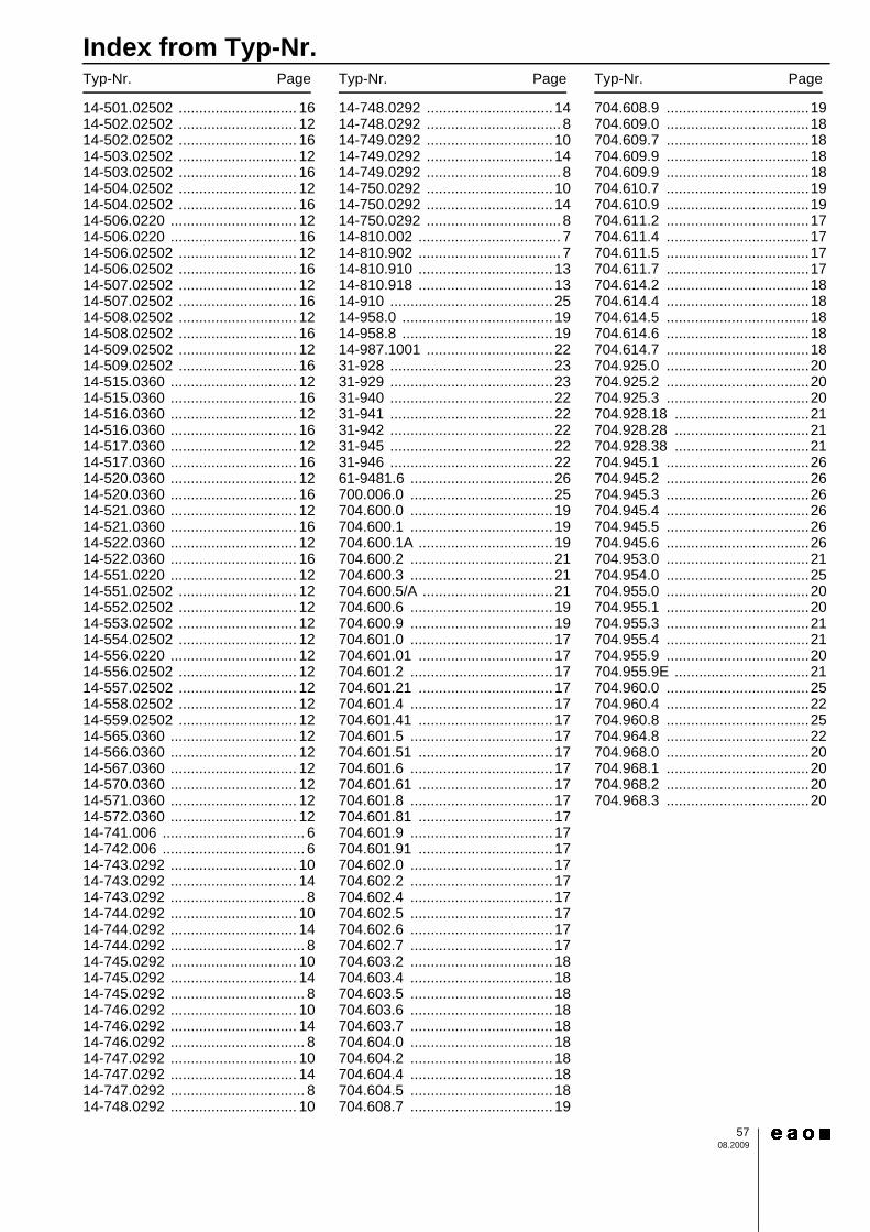
Index from Typ-Nr.
5708.2009
Typ-Nr. Page Typ-Nr. Page Typ-Nr. Page
14-501.02502 ............................. 1614-502.02502 ............................. 1214-502.02502 ............................. 1614-503.02502 ............................. 1214-503.02502 ............................. 1614-504.02502 ............................. 1214-504.02502 ............................. 1614-506.0220 ............................... 1214-506.0220 ............................... 1614-506.02502 ............................. 1214-506.02502 ............................. 1614-507.02502 ............................. 1214-507.02502 ............................. 1614-508.02502 ............................. 1214-508.02502 ............................. 1614-509.02502 ............................. 1214-509.02502 ............................. 1614-515.0360 ............................... 1214-515.0360 ............................... 1614-516.0360 ............................... 1214-516.0360 ............................... 1614-517.0360 ............................... 1214-517.0360 ............................... 1614-520.0360 ............................... 1214-520.0360 ............................... 1614-521.0360 ............................... 1214-521.0360 ............................... 1614-522.0360 ............................... 1214-522.0360 ............................... 1614-551.0220 ............................... 1214-551.02502 ............................. 1214-552.02502 ............................. 1214-553.02502 ............................. 1214-554.02502 ............................. 1214-556.0220 ............................... 1214-556.02502 ............................. 1214-557.02502 ............................. 1214-558.02502 ............................. 1214-559.02502 ............................. 1214-565.0360 ............................... 1214-566.0360 ............................... 1214-567.0360 ............................... 1214-570.0360 ............................... 1214-571.0360 ............................... 1214-572.0360 ............................... 1214-741.006 ................................... 614-742.006 ................................... 614-743.0292 ............................... 1014-743.0292 ............................... 1414-743.0292 ................................. 814-744.0292 ............................... 1014-744.0292 ............................... 1414-744.0292 ................................. 814-745.0292 ............................... 1014-745.0292 ............................... 1414-745.0292 ................................. 814-746.0292 ............................... 1014-746.0292 ............................... 1414-746.0292 ................................. 814-747.0292 ............................... 1014-747.0292 ............................... 1414-747.0292 ................................. 814-748.0292 ............................... 10
14-748.0292 ...............................1414-748.0292 ................................. 814-749.0292 ...............................1014-749.0292 ...............................1414-749.0292 ................................. 814-750.0292 ...............................1014-750.0292 ...............................1414-750.0292 ................................. 814-810.002 ................................... 714-810.902 ................................... 714-810.910 ................................. 1314-810.918 ................................. 1314-910 ........................................2514-958.0 .....................................1914-958.8 .....................................1914-987.1001 ...............................2231-928 ........................................2331-929 ........................................2331-940 ........................................2231-941 ........................................2231-942 ........................................2231-945 ........................................2231-946 ........................................2261-9481.6 ................................... 26700.006.0 ................................... 25704.600.0 ................................... 19704.600.1 ................................... 19704.600.1A ................................. 19704.600.2 ................................... 21704.600.3 ................................... 21704.600.5/A ................................ 21704.600.6 ................................... 19704.600.9 ................................... 19704.601.0 ................................... 17704.601.01 ................................. 17704.601.2 ................................... 17704.601.21 ................................. 17704.601.4 ................................... 17704.601.41 ................................. 17704.601.5 ................................... 17704.601.51 ................................. 17704.601.6 ................................... 17704.601.61 ................................. 17704.601.8 ................................... 17704.601.81 ................................. 17704.601.9 ................................... 17704.601.91 ................................. 17704.602.0 ................................... 17704.602.2 ................................... 17704.602.4 ................................... 17704.602.5 ................................... 17704.602.6 ................................... 17704.602.7 ................................... 17704.603.2 ................................... 18704.603.4 ................................... 18704.603.5 ................................... 18704.603.6 ................................... 18704.603.7 ................................... 18704.604.0 ................................... 18704.604.2 ................................... 18704.604.4 ................................... 18704.604.5 ................................... 18704.608.7 ................................... 19
704.608.9 ...................................19704.609.0 ...................................18704.609.7 ...................................18704.609.9 ...................................18704.609.9 ...................................18704.610.7 ...................................19704.610.9 ...................................19704.611.2 ...................................17704.611.4 ...................................17704.611.5 ...................................17704.611.7 ...................................17704.614.2 ...................................18704.614.4 ...................................18704.614.5 ...................................18704.614.6 ...................................18704.614.7 ...................................18704.925.0 ...................................20704.925.2 ...................................20704.925.3 ...................................20704.928.18 .................................21704.928.28 .................................21704.928.38 .................................21704.945.1 ...................................26704.945.2 ...................................26704.945.3 ...................................26704.945.4 ...................................26704.945.5 ...................................26704.945.6 ...................................26704.953.0 ...................................21704.954.0 ...................................25704.955.0 ...................................20704.955.1 ...................................20704.955.3 ...................................21704.955.4 ...................................21704.955.9 ...................................20704.955.9E .................................21704.960.0 ...................................25704.960.4 ...................................22704.960.8 ...................................25704.964.8 ...................................22704.968.0 ...................................20704.968.1 ...................................20704.968.2 ...................................20704.968.3 ...................................20
EAO AG Tannwaldstrasse 88 4601 Olten, Switzerland E-mail [email protected] Website www.eao.com Austria Phone +49 201 85 87 0 Fax +49 201 85 87 210 E-mail [email protected] Belgium Phone +32 3 777 82 36 Fax +32 3 777 84 19 E-mail [email protected] China Phone +852 27 86 91 41 Fax +852 27 86 95 61 E-mail [email protected] France Phone +33 1 64 43 37 37 Fax +33 1 64 43 37 49 E-mail [email protected] Germany Phone +49 201 85 87 0 Fax +49 201 85 87 210 E-mail [email protected] Italy Phone +39 035 481 0189 Fax +39 035 481 3786 E-mail [email protected] Japan Phone +81 3 5444 5411 Fax +81 3 5444 0345 E-mail [email protected] Netherlands Phone +31 78 653 17 00 Fax +31 78 653 17 99 E-mail [email protected] Sweden Phone +46 8 683 86 60 Fax +46 8 724 29 12 E-mail [email protected] Switzerland Phone +41 62 388 95 00 Fax +41 62 388 95 55 E-mail [email protected] United Kingdom Phone +44 1444 236 000 Fax +44 1444 236 641 E-mail [email protected] USA Phone +1 203 877 4577 Fax +1 203 877 3694 E-mail [email protected] Other Countries Phone +41 62 286 92 10 Fax +41 62 296 21 62 E-mail [email protected]
EA
O re
serv
es th
e rig
ht to
alte
r sp
ecifi
catio
ns w
ithou
t fur
ther
not
ice