Embed Size (px)
Citation preview

1
TIRE CHANGER (SWING ARM TIRE CHANGER)
OPERATION
MANUAL
DATE INSTALLED: _________________________ MODEL # _________________________________ SERIAL # _________________________________ MANUFACTURING DATE: ___________________
(ALL MODELS)
2
TABLE OF CONTENTS INTRODUCTION...............................................................page 3 TRANSPORTATION.........................................................page 4 UNPACKING.....................................................................page 4 SELECTING A LOCATION...............................................page 5 COMPONENTS................................................................page 6 ASSEMBLY.......................................................................page 7 IMPORTANT SAFETY INSTRUCTIONS..........................page 8 OPERATION.....................................................................page 9 Bead-Breaking.....................................................page 9 Clamping..............................................................page 10 Mount-Head (Adjustment & Positioning)..............page 11 Tire Removal........................................................page 13 Tire Mounting.......................................................page 14 Tire Inflation.........................................................page 16 TROUBLE-SHOOTING....................................................page 20 PARTS LIST.....................................................................page 21 Chassis................................................................page 21 Tower Assembly..................................................page 22 Main Pedal Assembly..........................................page 23 Turntable Assembly.............................................page 24 Bead Breaker Assembly......................................page 25 Motor & Transmission..........................................page 26 Inflation Pedal......................................................page 26 Distributor Valve..................................................page 27 WARRANTY INFORMATION...........................................page 28

3
INTRODUCTION Thank you for your purchase. Your machine is the result of decades of research, testing and development; and represents the most advanced technology on the market. The care with which you maintain and operate your Tire Changer will directly affect its overall performance and longevity.
PLEASE READ THIS ENTIRE MANUAL CAREFULLY AND COMPLETELY BEFORE OPERATING THE MACHINE.
PLEASE RECORD THE MODEL NUMBER AND THE SERIAL NUMBER (LOCATED ON THE BACK OF YOUR MACHINE) HERE AND ON THE COVER OF THIS MANUAL FOR FUTURE REFERENCE. Model Number: _______________________ Serial Number: _______________________ Manufacturing date: ___________________ THIS INFORMATION WILL BE REQUIRED SHOULD YOU EVER NEED TO CALL IN FOR PARTS OR TECHNICAL ASSISTANCE.
For assistance, please call: 1-800-535-0016
4
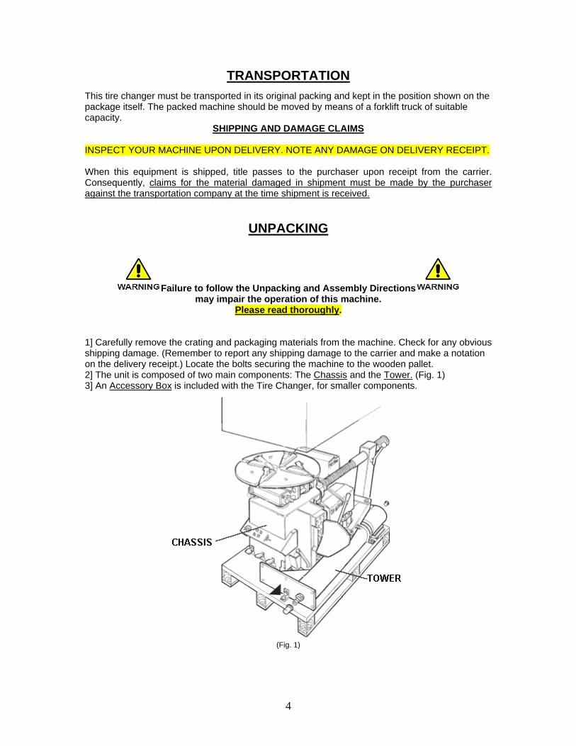
TRANSPORTATION This tire changer must be transported in its original packing and kept in the position shown on the package itself. The packed machine should be moved by means of a forklift truck of suitable capacity.
SHIPPING AND DAMAGE CLAIMS INSPECT YOUR MACHINE UPON DELIVERY. NOTE ANY DAMAGE ON DELIVERY RECEIPT. When this equipment is shipped, title passes to the purchaser upon receipt from the carrier. Consequently, claims for the material damaged in shipment must be made by the purchaser against the transportation company at the time shipment is received.
UNPACKING
Failure to follow the Unpacking and Assembly Directions may impair the operation of this machine.
Please read thoroughly. 1] Carefully remove the crating and packaging materials from the machine. Check for any obvious shipping damage. (Remember to report any shipping damage to the carrier and make a notation on the delivery receipt.) Locate the bolts securing the machine to the wooden pallet. 2] The unit is composed of two main components: The Chassis and the Tower. (Fig. 1) 3] An Accessory Box is included with the Tire Changer, for smaller components.
(Fig. 1)
5
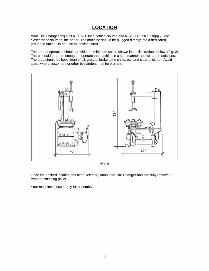
LOCATION Your Tire Changer requites a 110v-120v electrical source and a 120-145/psi air supply. The closer these sources, the better. The machine should be plugged directly into a dedicated, grounded outlet. Do not use extension cords. The area of operation should provide the minimum space shown in the illustrations below. (Fig. 2) There should be room enough to operate the machine in a safe manner and without restrictions. The area should be kept clean of oil, grease, brake lathe chips, etc. and clear of clutter. Avoid areas where customers or other bystanders may be present.
(Fig. 2)
Once the desired location has been selected, unbolt the Tire Changer and carefully remove it from the shipping pallet. Your machine is now ready for assembly.

6
COMPONENTS
It is a good idea to familiarize yourself with the components of your machine and the terms describing them. (Fig. 3)
(Fig. 3)

7
ASSEMBLY 1] Set the Tower on the Chassis and fasten securely with the nuts and bolts provided. (Fig. 4) Remove side-panel and connect hoses to the connector(s) on the bottom of the Tower and Inflation Box as needed. 2] Raise Hex-Shaft and lock in place with the Locking Lever. Remove the Screw securing the Plastic Cap on the Hex Shaft. Remove hex shaft Spring from the accessory box and install on Hex Shaft as shown. Replace Plastic Cap and Screw. (Fig. 5) 3] Install Inflation Box on side of tower. (Fig. 5) 4] Install safety "pop-off" valve (Design and location may vary.). (Fig. 5) 5] Secure air hoses to the Tower and Inflation Box, as necessary. (Fig. 5) 6] Mount Regulator Assembly on side of Chassis, connecting the two hoses which feed inside the cabinet(see Fig. 3). 7] Install Soap-Box and Lube Brush on side of Chassis (see Fig. 3 & 6).
(Note: The above procedure is a generic outline; specifics may vary. Your machine may arrive with some components already assembled, or slightly modified in design.)
(Fig. 4) (Fig. 5)
(Fig. 6)
8
IMPORTANT SAFETY INSTRUCTIONS
Read these Safety Instructions entirely! Read and understand all safety warning procedures before operating machine.
1] READ ALL WARNING LABELS and instruction manual prior to operation of this machine. Failure to comply with proper safety instructions may lead to serious harm or even death of operator and/or bystanders. 2] Improper use of this machine may cause damage to machine or cause personal harm or injury. 3] KEEP HANDS CLEAR of all pinch points. Check machine for damaged parts prior to operation. DO NOT USE MACHINE if any part(s) are broken or damaged. 4] NEVER EXCEED factory recommendations for air pressure of tire. Over-inflating the tire beyond factory recommendations can cause the tire to burst or explode. 5] Operators should inspect all tires and rims for possible defects prior to mounting. DO NOT ATTEMPT MOUNT DEFECTIVE TIRES. NEVER MOUNT A TIRE ON A DEFECTIVE WHEEL RIM. 6] ALWAYS MAKE SURE TIRE SIZE MATCHES RIM SIZE prior to mounting. MISMATCHED TIRE/RIM COMBINATIONS CAN EXPLODE. 7] This machine is not intended to be a restraining device for exploding tires, tubes or rims. All operators should take proper precautions to implement safety and to avoid personal injury or harm. 8] DO NOT lean over table while inflating tire. 9] KEEP HANDS AND BODY CLEAR at all times and as far back as possible during inflation. An exploding tire, rim or other wheel component can cause death to operator and/or bystanders. REMAIN CLEAR AT ALL TIMES. 10] To inflate tires, use short bursts while carefully monitoring the pressure, tire, rim and bead. 11] While seating beads, NEVER exceed 40/psi. If bead does not seat at 40/psi, immediately relieve pressure and check for damaged bead and/or other cause. 12] ALWAYS USE good quality tire lubricant when servicing tires. 13] Consider work area environment. Do not expose equipment to rain. Never operate machine in or around water or damp environments. Keep area well lit, clean and clear of debris. 14] Only trained operators should operate this machine. All non-trained personnel should be kept away from work area. Never let non-trained personnel come in contact with or operate machine. 15] DRESS PROPERLY. Never wear loose gloves, clothing or jewelry. They can be caught in moving parts. Non-skid steel-toe footwear is recommended when operating this machine. Wear protective hair-covering to contain long hair. Approved back-support braces are recommended when handling heavy tires. 16] ALWAYS WEAR SAFETY GOGGLES when operating this machine. 17] Guard against electric shock. This machine must be grounded while in use to protect the operator from electric shock, and prevent damage to electrical components. 18] Always unplug machine from outlets and air-supply before servicing. Never yank cord to disconnect it from the receptacle. Never operate machine in or around water or damp environments. 19] WARNING! Risk of explosion. This equipment has internal arcing or sparking parts which should not be exposed to flammable vapors. This machine should not be located in a recessed area or below floor level.
THIS SYMBOL POINTS OUT IMPORTANT SAFETY INSTRUCTIONS WHICH, IF NOT FOLLOWED, COULD ENDANGER THE PERSONAL SAFETY AND/OR PROPERTY OF YOURSELF AND OTHERS AND CAN CAUSE PERSONAL INJURY OR DEATH. READ AND FOLLOW ALL INSTRUCTIONS IN THIS MANUAL BEFORE ATTEMPTING TO OPERATE THIS MACHINE.

9
OPERATION
Intended Use: This Semi-Automatic Tire Changing Machine has been designed and manufactured for the specific purpose of
mounting and demounting tires on to and off of rims.
Any other use is to be considered incorrect and unreasonable. Purchaser assumes all responsibility for damage resulting from misuse or abuse of this machine.
-Note-
When first operating this machine, it is suggested that a steel wheel and used tire be used to familiarize yourself with the operation and use of the controls.
STEP 1
Breaking the Bead 1] REMOVE ALL WEIGHTS before servicing any tire. Weights left on the wheel can cause uneven clamping and may damage wheel and/or machine. Deflate the tire by removing the valve core. Allow ALL AIR TO ESCAPE. DO NOT try breaking the bead until the air has completely deflated from the tire.
ATTEMPTING TO BREAK BEADS ON PARTIALLY OR FULLY INFLATED TIRES IS UNSAFE
AND CAN CAUSE HARM TO MACHINE AND/OR OPERATOR.
-Note- To prevent damage to the machine and /or wheel, be sure the Turntable Clamps are retracted
before operating the Bead Breaker. 2] Position the wheel/tire next to the Bead Breaker blade, making sure to first demount the shallowest side of the wheel first. 3] With the tire/wheel in position, place the Bead Breaker blade as close to the rim as possible, paying close attention not to contact the sidewall or wheel itself.
-Note- If the blade is improperly positioned, damage to the tire or wheel can occur. If the sidewall starts
to collapse during the bead breaking process, STOP and reposition the blade. 4] Depress the Bead Breaker foot-pedal to actuate the blade and loosen the bead. Slowly apply pressure until the bead is unseated from the rim. (Fig. 7)
10
(Fig. 7)
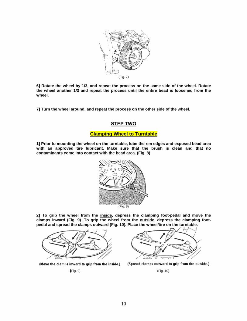
6] Rotate the wheel by 1/3, and repeat the process on the same side of the wheel. Rotate the wheel another 1/3 and repeat the process until the entire bead is loosened from the wheel. 7] Turn the wheel around, and repeat the process on the other side of the wheel.
STEP TWO
Clamping Wheel to Turntable 1] Prior to mounting the wheel on the turntable, lube the rim edges and exposed bead area with an approved tire lubricant. Make sure that the brush is clean and that no contaminants come into contact with the bead area. (Fig. 8)
(Fig. 8)
2] To grip the wheel from the inside, depress the clamping foot-pedal and move the clamps inward (Fig. 9). To grip the wheel from the outside, depress the clamping foot-pedal and spread the clamps outward (Fig. 10). Place the wheel/tire on the turntable.
(Fig. 9) (Fig. 10)
11
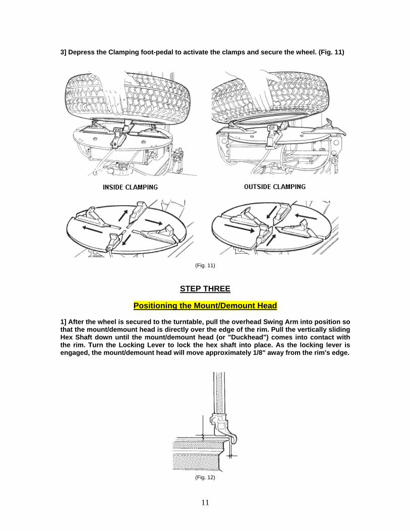
3] Depress the Clamping foot-pedal to activate the clamps and secure the wheel. (Fig. 11)
(Fig. 11)
STEP THREE
Positioning the Mount/Demount Head 1] After the wheel is secured to the turntable, pull the overhead Swing Arm into position so that the mount/demount head is directly over the edge of the rim. Pull the vertically sliding Hex Shaft down until the mount/demount head (or "Duckhead") comes into contact with the rim. Turn the Locking Lever to lock the hex shaft into place. As the locking lever is engaged, the mount/demount head will move approximately 1/8" away from the rim's edge.
(Fig. 12)
12
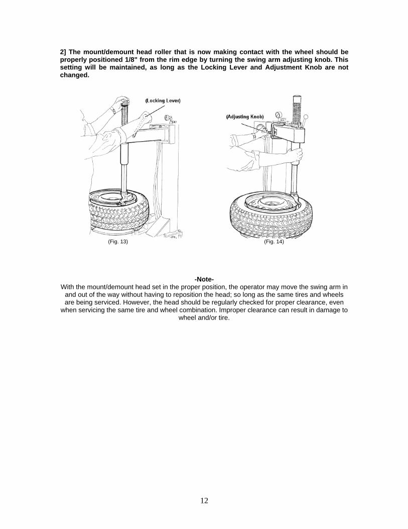
2] The mount/demount head roller that is now making contact with the wheel should be properly positioned 1/8" from the rim edge by turning the swing arm adjusting knob. This setting will be maintained, as long as the Locking Lever and Adjustment Knob are not changed.
(Fig. 13) (Fig. 14)
-Note- With the mount/demount head set in the proper position, the operator may move the swing arm in
and out of the way without having to reposition the head; so long as the same tires and wheels are being serviced. However, the head should be regularly checked for proper clearance, even
when servicing the same tire and wheel combination. Improper clearance can result in damage to wheel and/or tire.
13
STEP FOUR
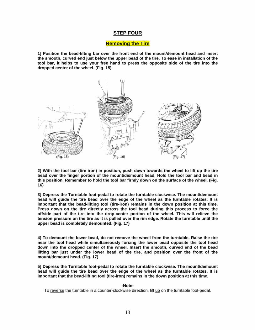
Removing the Tire 1] Position the bead-lifting bar over the front end of the mount/demount head and insert the smooth, curved end just below the upper bead of the tire. To ease in installation of the tool bar, it helps to use your free hand to press the opposite side of the tire into the dropped center of the wheel. (Fig. 15)
(Fig. 15) (Fig. 16) (Fig. 17) 2] With the tool bar (tire iron) in position, push down towards the wheel to lift up the tire bead over the finger portion of the mount/dismount head. Hold the tool bar and bead in this position. Remember to hold the tool bar firmly down on the surface of the wheel. (Fig. 16) 3] Depress the Turntable foot-pedal to rotate the turntable clockwise. The mount/demount head will guide the tire bead over the edge of the wheel as the turntable rotates. It is important that the bead-lifting tool (tire-iron) remains in the down position at this time. Press down on the tire directly across the tool head during this process to force the offside part of the tire into the drop-center portion of the wheel. This will relieve the tension pressure on the tire as it is pulled over the rim edge. Rotate the turntable until the upper bead is completely demounted. (Fig. 17) 4] To demount the lower bead, do not remove the wheel from the turntable. Raise the tire near the tool head while simultaneously forcing the lower bead opposite the tool head down into the dropped center of the wheel. Insert the smooth, curved end of the bead lifting bar just under the lower bead of the tire, and position over the front of the mount/demount head. (Fig. 17) 5] Depress the Turntable foot-pedal to rotate the turntable clockwise. The mount/demount head will guide the tire bead over the edge of the wheel as the turntable rotates. It is important that the bead-lifting tool (tire-iron) remains in the down position at this time.
-Note- To reverse the turntable in a counter-clockwise direction, lift up on the turntable foot-pedal.

14
DURING THE DEMOUNTING PROCEDURE, THE MOUNTING HEAD AND BEAD-LIFTING TOOL MAY ENCOUNTER RESISTANCE AND BECOME OBSTRUCTED. AT THIS TIME IT IS IMPORTANT THAT THE BEAD-LIFTING TOOL IS HELD FIRMLY DOWN. THE BEAD-LIFTING TOOL CAN BE PROPELLED OUTWARD IF RELEASED UNDER PRESSURE. IF THE MOUNT/DEMOUNT HEAD BECOMES JAMMED, CAREFULLY REVERSE THE TURNTABLE BY LIFTING UP ON THE FOOT-PEDAL.
STEP FIVE
Mounting the Tire 1] Be sure to READ ALL WARNING LABELS and instruction manual prior to operation. Failure to comply with proper safety instructions may lead to serious harm or even death of the operator and/or bystanders. Keep all unnecessary person(s) and bystanders out of the service area.
INSPECT ALL TIRES AND RIMS FOR POSSIBLE DEFECTS PRIOR TO MOUNTING. ALWAYS MAKE SURE TIRE SIZE MATCHES RIM SIZE PRIOR TO MOUNTING.
MISMATCHED TIRES CAN EXPLODE.
BE EXTREMELY CAUTIOUS WHEN MOUNTING ALL TIRES. NEVER MOUNT A TIRE OR TIRE/WHEEL COMBINATION THAT IS HANDED TO YOU BY ANOTHER EMPLOYEE OR CUSTOMER WITHOUT INSPECTING IT THOROUGHLY. DO NOT ATTEMPT TO MOUNT DEFECTIVE TIRES. NEVER MOUNT A TIRE ON A DEFECTIVE RIM.
MODULAR WHEELS SHOULD BE INSPECTED CLOSELY TO MAKE SURE THAT THE CENTER SECTION FASTENERS ARE IN PLACE
AND PROPERLY SECURED PRIOR TO MOUNTING OF TIRE(S).
15
IF A TIRE BECOMES DAMAGED DURING THE MOUNTING PROCESS, DO NOT ATTEMPT TO FINISH MOUNTING.
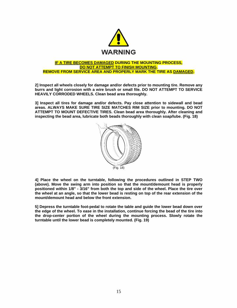
REMOVE FROM SERVICE AREA AND PROPERLY MARK THE TIRE AS DAMAGED. 2] Inspect all wheels closely for damage and/or defects prior to mounting tire. Remove any burrs and light corrosion with a wire brush or small file. DO NOT ATTEMPT TO SERVICE HEAVILY CORRODED WHEELS. Clean bead area thoroughly. 3] Inspect all tires for damage and/or defects. Pay close attention to sidewall and bead areas. ALWAYS MAKE SURE TIRE SIZE MATCHES RIM SIZE prior to mounting. DO NOT ATTEMPT TO MOUNT DEFECTIVE TIRES. Clean bead area thoroughly. After cleaning and inspecting the bead area, lubricate both beads thoroughly with clean soap/lube. (Fig. 18)
(Fig. 18)
4] Place the wheel on the turntable, following the procedures outlined in STEP TWO (above). Move the swing arm into position so that the mount/demount head is properly positioned within 1/8" - 3/16" from both the top and side of the wheel. Place the tire over the wheel at an angle, so that the lower bead is resting on top of the rear extension of the mount/demount head and below the front extension. 5] Depress the turntable foot-pedal to rotate the table and guide the lower bead down over the edge of the wheel. To ease in the installation, continue forcing the bead of the tire into the drop-center portion of the wheel during the mounting process. Slowly rotate the turntable until the lower bead is completely mounted. (Fig. 19)

16
(Fig. 19) (Fig. 20) 6] To mount the top bead, rotate the turntable so that the valve stem is located directly across from the mount/demount head (or at the 7-o'clock position). Lift the upper bead over the rear extension of the mount/demount head and below the front extension. To ease installation, continue forcing the bead of the tire into the drop-center portion of the wheel during the mounting process. Slowly rotate the turntable until the upper bead is completely mounted. (Fig. 20)
-Note- During the mounting procedure, the mounting head may encounter resistance and become
jammed. If the turntable stalls, slowly reverse the turntable rotation by lifting up on the foot-pedal. Reposition the tire and mounting head, then continue.
7] Release Hex Shaft Locking-Lever and move Swing Arm away from the Turntable.
STEP SIX
Inflating the Tire 1] Be sure to READ ALL WARNING LABELS and instruction manual prior to inflation of tire. Failure to comply with proper safety instructions may lead to serious harm or even death of the operator and/or bystanders. Keep all unnecessary person(s) and bystanders out of the service area.
THIS MACHINE IS NOT INTENDED TO BE A RESTRAINING DEVICE FOR EXPLODING TIRES, TUBES OR RIMS. KEEP HANDS AND BODY CLEAR AT ALL TIMES AND AS FAR BACK AS POSSIBLE DURING INFLATION. DO NOT LEAN OVER THE TIRE WHILE INFLATING. AN EXPLODING TIRE, RIM OR OTHER WHEEL COMPONENTS CAN CAUSE DEATH TO THE OPERATOR AND/OR BYSTANDER. REMAIN CLEAR AT ALL TIMES.
17
WHILE SEATING BEADS, NEVER EXCEED 40/PSI. IF BEAD DOES NOT SEAT AT 40/PSI, IMMEDIATELY RELIEVE PRESSURE AND CHECK
FOR DAMAGED BEAD AND/OR OTHER CAUSE. NEVER EXCEED THE FACTORY RECOMMENDED AIR PRESSURE OF A TIRE.
OVER INFLATING A TIRE BRYOND THE MANUFACTURER'S RECOMMENDATION CAN CAUSE TIRE TO BURST OR EXPLODE.
2] Connect the inflation hose to the tire valve stem, making sure that the hose clip is properly secured.
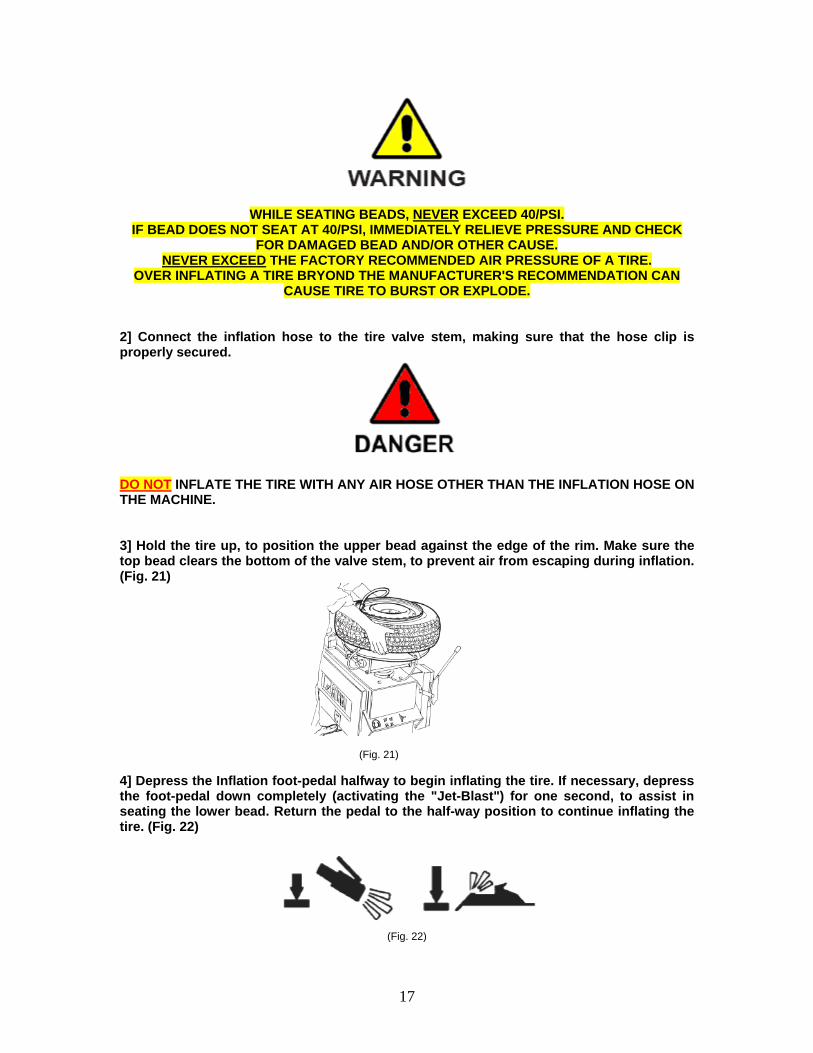
DO NOT INFLATE THE TIRE WITH ANY AIR HOSE OTHER THAN THE INFLATION HOSE ON THE MACHINE. 3] Hold the tire up, to position the upper bead against the edge of the rim. Make sure the top bead clears the bottom of the valve stem, to prevent air from escaping during inflation. (Fig. 21)
(Fig. 21) 4] Depress the Inflation foot-pedal halfway to begin inflating the tire. If necessary, depress the foot-pedal down completely (activating the "Jet-Blast") for one second, to assist in seating the lower bead. Return the pedal to the half-way position to continue inflating the tire. (Fig. 22)
(Fig. 22)

18
DO NOT DEPRESS THE "JET-BLAST" INFLATION PEDAL UNLESS A TIRE/WHEEL IS IN PLACE ON THE TURNTABLE. IF THE "JET-BLAST" INFLATION FOOT-PEDAL IS DEPRESSED WITHOUT A TIRE/WHEEL IN PLACE, DIRT OR OTHER DEBRIS COULD BE BLOWN UPWARD WITH EXTREME PRESSURE CAUSING INJURY TO THE OPERATOR OR BYSTANDERS.
-Note- If the bead refuses to seal after one or more attempts, you may wish to remove the valve stem core to assist in the bead sealing process. Once the bead is seated, remove the inflation hose
and re-install the valve stem core. 5] Once the bead is sealed and the tire begins to inflate, step away. During the bead seating and inflation process STAND BACK AND KEEP HANDS AND ENTIRE BODY CLEAR.
KEEP HANDS AND BODY CLEAR AT ALL TIMES AND AS FAR BACK AS POSSIBLE DURING INFLATION. DO NOT LEAN OVER THE TIRE WHILE INFLATING. AN EXPLODING TIRE, RIM OR OTHER WHEEL COMPONENT CAN CAUSE DEATH TO OPERATOR AND/OR BYSTANDER. REMAIN CLEAR AT ALL TIMES. 6] As the pressure in the tire increases, the beads will move outward on the wheel and "pop" when they seat completely. If the beads refuse to seat during inflation, relieve the pressure immediately and check for possible causes.
WHILE SEATING BEADS, NEVER EXCEED 40/PSI. IF BEAD DOES NOT SEAT AT 40/PSI IMMEDIATELY REIEVE PRESSURE AND CHECK FOR DAMAGED BEAD AND/OR OTHER CAUSE.
19
7] Continue to depress the Inflation foot-pedal half-way until the desired air pressure is shown on the pressure gauge.
-Note- To release air pressure with the inflation hose attached to the tire, press the pressure release
valve button on the Inflation Box.
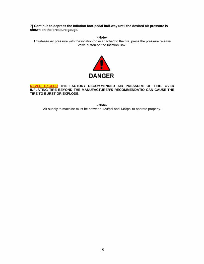
NEVER EXCEED THE FACTORY RECOMMENDED AIR PRESSURE OF TIRE. OVER INFLATING TIRE BEYOND THE MANUFACTURER'S RECOMMENDATIO CAN CAUSE THE TIRE TO BURST OR EXPLODE.
-Note- Air supply to machine must be between 120/psi and 145/psi to operate properly.
20
TROUBLE-SHOOTING MOUNT HEAD SCRATCHES RIMS 1] Rim not mounted properly. 2] Mount-head is not adjusted properly. 3] Locking-plate is not adjusted properly. 4] Bent or damaged parts. AIR LEAKS 1] Isolate leak. 2] Check regulator for proper air flow. 3] Check tubing, fittings or components for leaks; and replace as applicable. 4] Air continuously leaks through clamps: Bad pedal valve or bad distributor valve. PEDAL PROBLEMS 1] Broken pedal: Replace 2] Pedal does not operate: Broken or disconnected: inspect, and replace if necessary. 3] Pedal sticks: Broken spring, linkage or defective valve: inspect, and replace if necessary. INFLATION ISSUES 1] Air continuously leaks through clamps: Bad pedal valve or bad distributor valve. 2] Not enough pressure: Check air pressure at regulator. 3] Will not inflate tire: 4] Will not seat bead: BEAD-BREAKING ISSUES 1] Insufficient force to break bead: Check for air pressure, crimps in tubing or leaks. 2] Bead breaker is slow: Verify oil in lubricator. 3] Will not release tire: Check for air obstruction, or damaged cylinder. CLAMPING ISSUES 1] Clamps do not move. 2] Clamps move in, but not out. 3] Clamps move in, then out on their own. 4] Clamps move out, and stay out: Bad rotary valve. TURNTABLE ISSUES 1] Table only turns in one direction: Check Cam switch. 2] Motor hums or pops breaker: Check cam switch and motor; replace if necessary. 3] Does not turn at all: Check belt, power, transmission or wiring, correct as necessary. 4] Turns in one direction only: Check wiring and switch, and linkage on pedal: replace or correct.
21
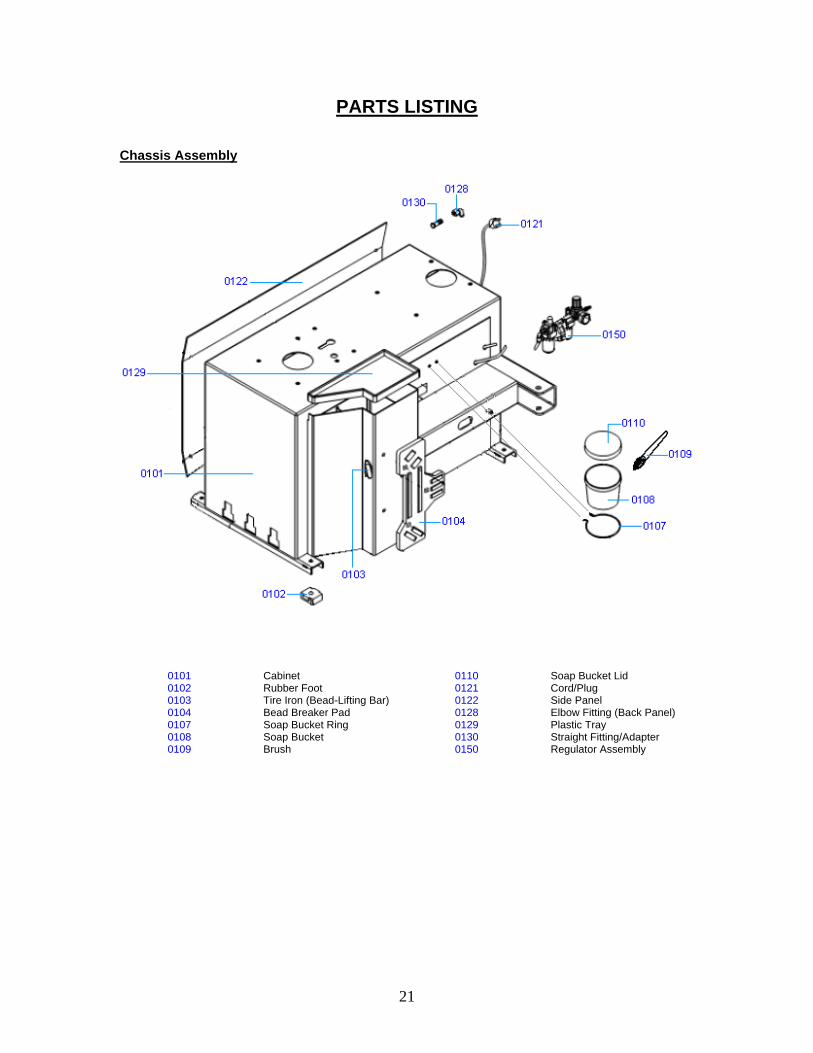
PARTS LISTING Chassis Assembly
0101 Cabinet 0110 Soap Bucket Lid 0102 Rubber Foot 0121 Cord/Plug 0103 Tire Iron (Bead-Lifting Bar) 0122 Side Panel 0104 Bead Breaker Pad 0128 Elbow Fitting (Back Panel) 0107 Soap Bucket Ring 0129 Plastic Tray 0108 Soap Bucket 0130 Straight Fitting/Adapter 0109 Brush 0150 Regulator Assembly
22
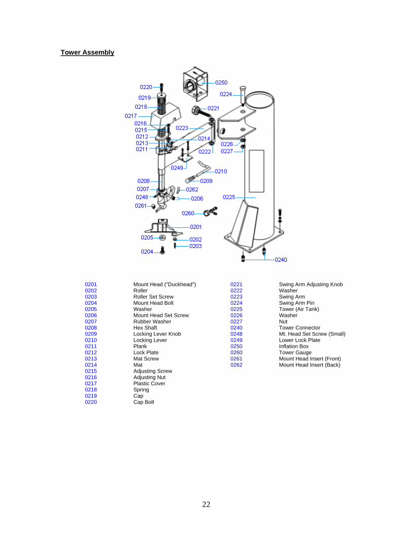
Tower Assembly
0201 Mount Head ("Duckhead") 0221 Swing Arm Adjusting Knob 0202 Roller 0222 Washer 0203 Roller Set Screw 0223 Swing Arm 0204 Mount Head Bolt 0224 Swing Arm Pin 0205 Washer 0225 Tower (Air Tank) 0206 Mount Head Set Screw 0226 Washer 0207 Rubber Washer 0227 Nut 0208 Hex Shaft 0240 Tower Connector 0209 Locking Lever Knob 0248 Mt. Head Set Screw (Small) 0210 Locking Lever 0249 Lower Lock Plate 0211 Plank 0250 Inflation Box 0212 Lock Plate 0260 Tower Gauge 0213 Mat Screw 0261 Mount Head Insert (Front) 0214 Mat 0262 Mount Head Insert (Back) 0215 Adjusting Screw 0216 Adjusting Nut 0217 Plastic Cover 0218 Spring 0219 Cap 0220 Cap Bolt
23
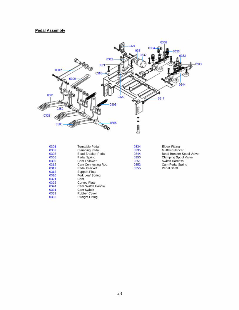
Pedal Assembly
0301 Turntable Pedal 0334 Elbow Fitting 0302 Clamping Pedal 0335 Muffler/Silencer 0303 Bead Breaker Pedal 0344 Bead Breaker Spool Valve 0306 Pedal Spring 0350 Clamping Spool Valve 0309 Cam Follower 0351 Switch Harness 0312 Cam Connecting Rod 0352 Cam Pedal Spring 0317 Pedal Bracket 0355 Pedal Shaft 0318 Support Plate 0320 Fork Leaf Spring 0321 Cam 0322 Curved Plate 0324 Cam Switch Handle 0331 Cam Switch 0332 Rubber Cover 0333 Straight Fitting
24
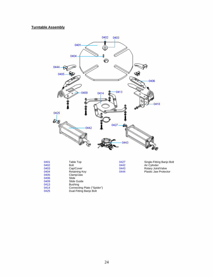
Turntable Assembly
0401 Table Top 0427 Single-Fitting Banjo Bolt 0402 Bolt 0442 Air Cylinder 0403 Cap/Cover 0443 Rotary Joint/Valve 0404 Retaining Key 0444 Plastic Jaw Protector 0405 Clamp/Jaw 0406 Slide 0409 Slide Guide 0413 Bushing 0414 Connecting Plate ("Spider") 0425 Dual-Fitting Banjo Bolt
25
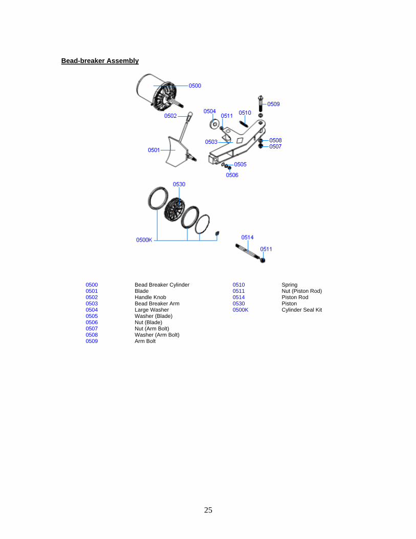
Bead-breaker Assembly
0500 Bead Breaker Cylinder 0510 Spring 0501 Blade 0511 Nut (Piston Rod) 0502 Handle Knob 0514 Piston Rod 0503 Bead Breaker Arm 0530 Piston 0504 Large Washer 0500K Cylinder Seal Kit 0505 Washer (Blade) 0506 Nut (Blade) 0507 Nut (Arm Bolt) 0508 Washer (Arm Bolt) 0509 Arm Bolt
26
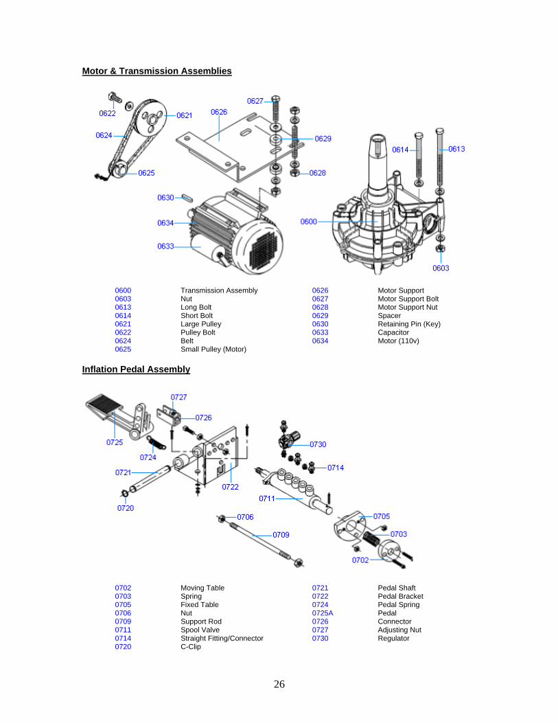
Motor & Transmission Assemblies
0600 Transmission Assembly 0626 Motor Support 0603 Nut 0627 Motor Support Bolt 0613 Long Bolt 0628 Motor Support Nut 0614 Short Bolt 0629 Spacer 0621 Large Pulley 0630 Retaining Pin (Key) 0622 Pulley Bolt 0633 Capacitor 0624 Belt 0634 Motor (110v) 0625 Small Pulley (Motor) Inflation Pedal Assembly
0702 Moving Table 0721 Pedal Shaft 0703 Spring 0722 Pedal Bracket 0705 Fixed Table 0724 Pedal Spring 0706 Nut 0725A Pedal 0709 Support Rod 0726 Connector 0711 Spool Valve 0727 Adjusting Nut 0714 Straight Fitting/Connector 0730 Regulator 0720 C-Clip
27
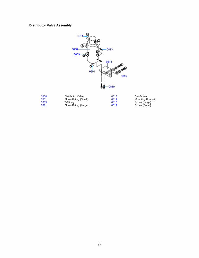
Distributor Valve Assembly
0800 Distributor Valve 0813 Set-Screw 0801 Elbow Fitting (Small) 0814 Mounting Bracket 0809 T-Fitting 0815 Screw (Large) 0811 Elbow Fitting (Large) 0819 Screw (Small)
28
Eagle Global Series Warranty
Eagle Equipment warrants to the original retail purchaser of an Eagle Global Tire Changer or Wheel Balancer that it will replace without charge any part found under normal use, in the United states or Canada, to be defective in materials or workmanship, for a period of one (1) year from date of purchase. Warranty covers parts only; purchaser is responsible for any and all labor requirements.
Exclusions This warranty will not apply to any machine:
1. Which has not been operated or maintained according to specifications 2. Which has been abused, misused altered or improperly maintained 3. Which has been improperly installed or assembled
Other limitations This warranty does not cover:
1. Parts needed for normal maintenance 2. Wear parts, which include but are not limited to, speed-nuts, cones, mount heads, and
inserts 3. On-site labor
Eagle Equipment reserves the right to make improvements and/or design changes to its equipment without any obligation to previously sold, assembled or fabricated equipment.
There is no other express warranty on the Eagle Global Series equipment and this warranty is exclusive of and in lieu of all other warranties, expressed or implied, including all warranties of merchantability and fitness for a particular purpose.
To the fullest extent allowed by law, Eagle Equipment shall not be liable for loss of use, inconvenience, lost time, commercial loss or other incidental or consequential damages
Some States do not allow exclusion or limitation of consequential damages or how long an implied warranty lasts, so that the above limitations and exclusions may not apply. This warranty gives you specific legal rights and you may have other rights, which may vary from State to State.