Embed Size (px)
Citation preview

EAGLE GOLD PROJECT
ROAD CONSTRUCTION PLAN
Version 2017-01
JUNE 2017

THIS PAGE INTENTIONALLY LEFT BLANK

Eagle Gold Project Road Construction Plan
Document Control
i
DOCUMENT CONTROL
Submission History
Version Number
Version Date Document Description and Revisions Made
2013-01 Sept 2013 Original submission to the Department of Energy, Mines and Resources in support of an application for a Quartz Mining Licence allowing for preliminary construction activities.
2014-01 May 2014
Revisions made in support of an application to the Yukon Water Board for a Type A Water Use License for the full Construction, Operation and Closure of the Project. Version 2014-01 was also submitted to the Department of Energy, Mines and Resources in support of an application for a Quartz Mining Licence allowing the full Construction, Operation and Closure of the Project.
2017-01 June 2017 Revisions made to address the conditions of the Quartz Mining Licence QML-0011 and act as a “subsequent revision” for QZ14-041
Version 2017-01 of the Road Construction Plan has been revised in June 2017 to update Version 2014-01 submitted in March 2015. The table below is intended to identify modifications to the Plan and provide the rationale for such modifications
Version 2017-01 Revisions
Section Revision/Rationale
1.2 Project Schedule
Updates to the Project schedule.
2 Site Description
History of Project area removed as it is not relevant to the scope of the Plan.
2.2 Geologic Conditions
Geology of the Eagle Zone removed as it is not relevant to the scope of the Plan.
2.2.5 Geologic Hazards
Rearrangement and minor modification of text for readability purposes.
3.1 Vegetation Clearing and
Grubbing Rearrangement and minor modification of text for readability purposes.
3.2 Site Preparation
Updated text to reflect material volume estimates based on optimized site layout.
3.3 Site Roads
Updated text to reflect refined road dimensions and classifications based on optimized site layout.
Updated Figure 3.3-1 to show optimized road alignments.
3.3.6 Schedule and
Quantities
Modified location in document for discussion on schedule and quantities for readability purposes.
Insertion of Table 3.3-1 to provide greater detail on quantities. Insertion of Table 3.3-2 to provide greater detail on locations and specifications
for the required culverts.
4 Revision of text to reflect refined road design and specifications.

Eagle Gold Project Road Construction Plan
ii
Section Revision/Rationale Road Design and
Specifications Updates to Figures 4.1-1 to 4.1-4 to reflect road design, specifications and
alignment.
4.2.1 Access Road
Upgrading
Inclusion of text to accurately reflect SGC commitment to the construction of the South McQuesten parking area.
4.2.5 Operational Access
Control Minor text revision to clarify operational access control.
6 Geochemical
Considerations
Inclusion of text to reiterate the geochemical monitoring described in the Environmental Monitoring, Surveillance and Adaptive Management plan and the geochemical parameters for construction rock specified in the regulatory approvals.

Eagle Gold Project Road Construction Plan
Table of Contents
iii
TABLE OF CONTENTS
1 Introduction ............................................................................................................................ 1
1.1 Project Summary ............................................................................................................ 1
1.2 Project Schedule ............................................................................................................ 1
1.3 Scope and Objectives .................................................................................................... 1
2 Site Description ...................................................................................................................... 3
2.1 General Environmental Conditions ................................................................................ 3
2.1.1 Climate ............................................................................................................ 3
2.1.2 Geomorphology ............................................................................................... 3
2.1.3 Vegetation ....................................................................................................... 4
2.2 Geologic Conditions ....................................................................................................... 4
2.2.1 Overburden ...................................................................................................... 4
2.2.2 Bedrock ........................................................................................................... 5
2.2.3 Groundwater .................................................................................................... 5
2.2.4 Permafrost ....................................................................................................... 5
2.2.5 Geological Hazards ......................................................................................... 6
2.2.6 Hydrology ........................................................................................................ 6
3 Site Preparation Considerations .......................................................................................... 8
3.1 Vegetation Clearing and Grubbing ................................................................................. 8
3.2 Site Preparation ............................................................................................................. 8
3.3 Site Roads ...................................................................................................................... 9
3.3.1 Haul Road ...................................................................................................... 10
3.3.2 Mine Service Road ........................................................................................ 10
3.3.3 Auxiliary Roads.............................................................................................. 10
3.3.4 Temporary Construction Trails ...................................................................... 10
3.3.5 Schedule and Quantities ............................................................................... 12
4 Road Design and Specifications ........................................................................................ 13
4.1 Site Roads .................................................................................................................... 13
4.1.1 Road Base ..................................................................................................... 14
4.1.2 Road Surfacing Material ................................................................................ 14
4.2 Access Road to Eagle Gold Project ............................................................................. 15
4.2.1 Access Road Upgrading ................................................................................ 15
4.2.2 Construction Staging Areas ........................................................................... 18
4.2.3 Traffic Volume ............................................................................................... 18
4.2.4 Construction Control Measures ..................................................................... 19

Eagle Gold Project Road Construction Plan
Table of Contents
iv
4.2.5 Operational Access Control ........................................................................... 19
4.2.6 Temporary and Permanent Access Closure ................................................. 20
5 Borrow Sources ................................................................................................................... 26
5.1 Mine Site Haul and Secondary Roads ......................................................................... 26
5.2 Access Road ................................................................................................................ 26
6 Geochemical Considerations ............................................................................................. 29
7 Geotechnical Testing........................................................................................................... 32
8 Best Management Practices ............................................................................................... 34
8.1 Sediment and Erosion Control ..................................................................................... 34
8.2 Dust Control ................................................................................................................. 35
8.3 Site Isolation ................................................................................................................. 35
8.4 Culvert Installation ........................................................................................................ 35
8.5 Environmental Monitoring ............................................................................................ 36
8.6 Decommissioning and Closure .................................................................................... 36
List of Tables
Table 1.2-1: Tentative Project Schedule ......................................................................................... 1
Table 3.3-1: Road Material Quantities .......................................................................................... 12
Table 3.3-2: Culverts by Road ...................................................................................................... 12
Table 4.1-1: Permanent Cut Slope Angles ................................................................................... 14
Table 4.1-2: Design Criteria for Roads ......................................................................................... 15
Table 7.1-1: ARD Classification for Each Group of Samples ....................................................... 29

Eagle Gold Project Road Construction Plan
Table of Contents
v
List of Figures
Figure 1.3-1: Property Location Map ................................................................................................ 2
Figure 3.3-1: Overall Site Roads .................................................................................................... 11
Figure 4.1-1: Overall Site Roads Profiles ....................................................................................... 21
Figure 4.1-2: Haul Roads Typical Cross Sections ......................................................................... 22
Figure 4.1-3: Mine Service Road Typical Cross Section ............................................................... 23
Figure 4.1-4: Auxiliary Roads Typical Cross Section ..................................................................... 24
Figure 4.2-1: Road Construction Staging Areas ............................................................................ 25
Figure 5.1-1: Boreholes and Proposed Borrow Sites ..................................................................... 28

Eagle Gold Project Road Construction Plan
Table of Contents
vi
List of Acronyms and Abbreviations
% ................................................................................................................................................. percent
< ................................................................................................................................................ less than
> ........................................................................................................................................... greater than
AP ............................................................................................. acid potential in kg CaCO3/t equivalent
ARD ............................................................................................................................ acid rock drainage
asl ................................................................................................................................... above sea level
BC ................................................................................................................................. British Columbia
BGC ..................................................................................................................... BGC Engineering Ltd.
BH ............................................................................................................................................. borehole
BMP ............................................................................................................. Best Management Practice
CaCO3 ........................................................................................................................ calcium carbonate
cm .......................................................................................................................................... centimetre
FNNND............................................................................................... First Nation of Na-Cho Nyäk Dun
g/t .................................................................................................................................. grams per tonne
hr ...................................................................................................................................................... hour
HLF ............................................................................................................................ Heap leach facility
HPW ........................................................................ Yukon Department of Highways and Public Works
km ........................................................................................................................................... kilometres
km2 .............................................................................................................................. square kilometres
masl. ................................................................................................................... metres above sea level
m .................................................................................................................................................. metres
m2 ..................................................................................................................................... square metres
ML .................................................................................................................................... metal leaching
Mt ............................................................................................................... megatonnes (million tonnes)
Mt/y ....................................................................................................................... megatonnes per year
Non-PAG ............................................................................................... Non-potentially acid generating
NP .............................................................................. neutralization potential in kg CaCO3/t equivalent
NP/AP ............................................................................... neutralization potential to acid potential ratio

Eagle Gold Project Road Construction Plan
Table of Contents
vii
PAG ................................................................................................................ Potential Acid Generation
pH .......................................................................................... potential of hydrogen (measure of acidity)
Project ....................................................................................................................... Eagle Gold Project
QML ...................................................................................................................... quartz mining licence
RoW ...................................................................................................................................... right of way
SGC ................................................................................................................... StrataGold Corporation
SMR .................................................................................................................. South McQuesten Road
TAC ............................................................................................. Transportation Association of Canada
WRSA ............................................................................................................... waste rock storage area

THIS PAGE INTENTIONALLY LEFT BLANK

Eagle Gold Project Road Construction Plan
Section 1 Introduction
1
1 INTRODUCTION
1.1 PROJECT SUMMARY
StrataGold Corporation (SGC), a directly held wholly owned subsidiary of Victoria Gold Corp. has proposed to construct, operate, close and reclaim a gold mine in central Yukon. The Eagle Gold Project (the Project) is located 85 km from Mayo, Yukon using existing highway and access roads. The Project will involve open pit mining at a production rate of approximately 10 million tonnes per year (Mt/y) ore, and gold extraction using a three stage crushing process, heap leaching, and a carbon adsorption, desorption, and recovery system over a 10 year mine life.
1.2 PROJECT SCHEDULE
A summary of the Project schedule is provided in Table 1.2-1. This construction schedule is tentative and dependent upon receipt of the regulatory approvals, project financing, contractor availability and seasonal limitations.
Table 1.2-1: Tentative Project Schedule
Phase Schedule
Construction 2017 – 2019
Operations (10 years) 2019 – 2029
Reclamation and Closure (10 years) 2029 – 2039
Post-Closure Monitoring (5 years or as required) 2039 – 2044
1.3 SCOPE AND OBJECTIVES
This Road Construction Plan describes the design and construction of new site haul roads and service roads within the Project footprint. The site is accessible by existing public roads (the South McQuesten Road and Haggart Creek Road) which will require minor upgrades to support Project traffic volumes and loads.
Figure 1.3-1 shows the location of the Eagle Gold Project property.

_̂
!
! !
_̂
Elsa
Mayo
Keno Hill
400000
400000
420000
420000
440000
440000
460000
460000
480000
480000
500000
500000
706
000
0
706
000
0
708
000
0
708
000
0
710
000
0
710
000
0
EAGLE GOLD PROJECTYUKON TERRITORY
Projection: Drawn By:
Date: Figure:
Legend:
³!
!
!
!
!
!
! !
!
!
!
!
!
!
!
!
! !
!!
!
!
!
!
!
"
!
!
_̂
NORTHWESTTERRITORIES
YUKONTERRITORY
ALASKA
Beaufort Bay
Great BearLake
Faro
ElsaMayo
Atlin
DelineTulita
Inuvik
Teslin
Dawson
Aklavik
Wrigley
Old Crow
Paulatuk
Carcross
Carmacks
Fort Liard
Ross River
Tuktoyaktuk
Watson Lake
Tsiigehtchic
Norman Wells
Fort McPherson
Fort Good Hope
Pelly Crossing
HainesJunction
Whitehorse
Eagle Gold Project
0 6 123
Kilometres
_̂ Eagle Gold Project
! Town / Village
Road
Watercourse
Category A Settlement Land
Category B Settlement Land
StrataGold Claims
Other Claims
#Haggart Creek Road
#
South McQuestenRoad
#
Silver Trail
NAD 83 Zone 8N HC
2017/06/01 1.3-1
Prpoerty Location

Eagle Gold Project Road Construction Plan
Section 2 Site Description
3
2 SITE DESCRIPTION
The Project is located approximately 45 km north-northeast of the Village of Mayo, Yukon (by flight) and has year round road access using an existing series of paved and gravel roads (Figure 1.3-1). The driving distance to the Project site from Mayo is 85 km. Access to the Project site from the Silver Trail Highway (Highway 11) will be via the existing South McQuesten Road (SMR) and the Haggart Creek Road (HCR). Together, the SMR and HCR comprise a 45 km road, which is divided by the South McQuesten River. The section of the road between the Silver Trail and the South McQuesten River is referred to as the SMR (km 0 to 22.9), whereas the section of the road between the river and the Project is referred to as the HCR (km 23 to 45). Both roads are public roads, regulated under the Yukon Highways Act; however, the SMR is maintained during summer only by the Yukon Government Department of Highways and Public Works (HPW), whereas the HCR is considered a “publ ic unmaintained” road.
2.1 GENERAL ENVIRONMENTAL CONDITIONS
2.1.1 Climate The Dublin Gulch area is characterized by a continental-type climate with moderate annual precipitation and a large temperature range. Summers are short and can be hot, while winters are long and cold with moderate snowfall. Autumn and winter temperature inversions do occur at the site, as expected in mountainous regions.
Rainstorm events can occur frequently during the summer and may contribute between 30 and 40% of the annual precipitation. Higher elevations are snow-free by mid-June. Frost may occur at any time during the summer or fall. The estimated mean annual precipitation at the Project site ranges from 357 to 652 mm about half of which falls as snow.
2.1.2 Geomorphology The majority of Project area was un-glaciated during the last glacial period, and has not been glaciated for more than 200,000 years. The Project area displays physiographic characteristics of the unglaciated areas of the region, with narrow, V-shaped valleys and rounded upland surfaces. The valleys are deep and narrow to the head of streams, where they rise steeply and end abruptly.
Despite the extensive time since glaciation, evidence of glacial-ice action is still visible. This historic glaciation is responsible for the formation of the tributaries of Dublin Gulch, including, from east to west, Cascallen, Bawn Boy, Olive, Ann, Stewart, Eagle, Suttles and Platinum gulches. Within these gulches, the post-glacial terrain has been modified by gravity, water, and freeze-thaw mechanics, as evidenced by the many headscarps of landslides, and observed rock and debris slides. Most of the landslides are historic, but there are a few areas of ongoing rock fall that continue to modify the terrain, particularly in the Stewart, Bawn Boy, and Olive gulches.
The topography of the Property area is characterized by rolling hills and plateaus ranging in elevation from approximately 800 MASL to a local maximum of 1,650 MASL at the summit of Potato Hills, and is drained by deeply-incised creeks and canyons. The ground surface is covered by residual soil and felsenmeer. Outcrops are rare, generally less than two percent of the surface area, and are limited to ridge tops and creek walls. Patchy permafrost occurs on north-facing slopes.

Eagle Gold Project Road Construction Plan
Section 2 Site Description
4
2.1.3 Vegetation Two ecological zones have been recognized for the Project: the higher elevation Subalpine zone and the lower Forested zone. The Subalpine zone occurs on the ridge tops and high plateaus above 1,225 MASL. Tree cover is discontinuous or absent at this elevation. Dwarf birch, willows, ericaceous shrubs, herbs, mosses and lichens dominate the vegetation.
The forested zone includes the valley bottoms, and the slopes of the mountains below the treeline. The elevation of this zone is from the lowest point in the Project area up to the Subalpine zone. In the valley bottoms, forests are dominated by open canopy stands of black spruce. However, white spruce is found along creeks, rivers, and the well-drained slopes. On the mid to lower slopes, continuous stands of subalpine fir occur along with minor components of white spruce, Alaska birch, trembling aspen, and black spruce. On the upper slopes, open subalpine fir stands are predominant with trees becoming smaller and more spread out with increasing elevation.
2.2 GEOLOGIC CONDITIONS
Geologic conditions at the Project site have been strongly influenced by the geotectonic forces that produced the Eagle Gold deposit. The folding, faulting and plutonic activities have resulted in relatively weak rock mass with relatively poor mechanical properties. The latitude of the Property has complicated matters further with frost fracturing and permafrost.
The Property is located on the northern limb of the McQuesten Antiform and is underlain by Proterozoic to Lower Cambrian-age Hyland Group metasediments and the Dublin Gulch intrusion, a granodioritic stock. The stock has been dated at approximately 93 Ma, and is assigned to the Tombstone Plutonic Suite. The Dublin Gulch stock is comprised of four phases, the most significant of which is granodiorite.
At least four periods of faulting have been documented in the Dublin Gulch area including low-angle thrusting and bedding-plane faults and normal faults with north, northeast, northwest, and easterly trends. North-trending faults are inferred to have displaced portions of the Dublin Gulch stock and one of these is interpreted to form the eastern boundary of the Eagle Zone.
2.2.1 Overburden Overburden soils encountered on the sloping ground at the Project site typically consist of a veneer of organic soils overlying a blanket of colluvium, which overlies weathered bedrock.
Overburden soil conditions are distinctly different in the Dublin Gulch valley bottom from those encountered above the valley bottom in Ann Gulch and south of Dublin Gulch along the southern edge of the proposed heap leach facility. In the uplands above the valley bottom, the upper soil unit consists of a thin horizon of organic soil, rootlets, woody debris and plant matter ranging from 0.1 to 2.7 m in thickness and averaging approximately 0.3 m. The organic cover above the valley bottom overlies colluvium ranging in thickness from 0.2 to 15.2 m, and averaging approximately 2.9 m. The colluvium consists of loose to compact angular gravel with occasional cobbles in a silt and sand matrix, derived from transported weathered metasedimentary bedrock. The colluvium may also include variable amounts of organics, which are often observed in distinct layers within the colluvium.
The overburden soils in the valley bottom have been reworked by historical placer mining activities. Placer tailings (fill) are observed from the ground surface to bedrock, with thicknesses ranging between 2.4 and 16.5 m, and an average thickness of approximately 6.6 m. The material encountered is generally a well graded,
Eagle Gold Project Road Construction Plan
Section 2 Site Description
5
loose to dense, silty sand and gravel, ranging to sand and gravel with some silt and occasional cobbles and boulders. Loose and moist zones have been encountered within the placer tailings. There is little to no vegetative cover on the placer tailings.
Glacial till is generally only encountered on the lower flanks of the north and west-facing slopes located north and west of the proposed open pit, above Dublin Gulch and Haggart Creek. The till is often overlain by colluvium. Placer tailings (fill) cover most of the valley bottom of Dublin Gulch and Haggart Creek. Alluvial soils are occasionally encountered along undisturbed valley-bottom areas.
2.2.2 Bedrock Bedrock is found in the uplands above Dublin Gulch immediately below colluvium at depths ranging between 0.0 and 16.8 m below existing grade (average depth to bedrock at 3.5 m where observed). Bedrock is found in the valley bottom at depths ranging between 1.5 and 16.5 m below existing grade, with an average depth to bedrock at 6.2 m where observed.
2.2.3 Groundwater Groundwater flow in the bedrock occurs in fractures and fault zones, while preferentially flowing through more permeable (and porous) sediments within the surficial deposits. General orientation of groundwater flow contours mimic the topography of the site as groundwater flows from the highest areas to lowest.
Across the project site groundwater generally is found deeper at higher elevations (i.e., generally more than six meters below ground) and shallow to artesian at lower elevations and in valley bottoms. Springs and seeps have been observed in a few locations where valley bottoms have narrowed. These are typically associated with the re-emergence of a stream from channel deposits and some of the larger springs have caused surface depressions by destabilizing the soils locally.
Groundwater recharge occurs at higher elevations throughout the Dublin Gulch-Eagle Creek drainage basin and ultimately discharges to surface water (in some cases as seeps and springs) at lower elevations in the valley or directly to surface streams, or ultimately into Haggart Creek. The main groundwater flow in conjunction with the highest groundwater elevations is expected to occur during the snowmelt in late spring (e.g., May to June) after thawing of the shallow sediment.
Groundwater levels within the lower Dublin Gulch Valley were observed to have delayed trends related to higher groundwater levels after spring freshet or rainfall events and lower groundwater levels during dry summer periods.
2.2.4 Permafrost The Project site is located in a region of discontinuous permafrost. Frozen ground distribution within the Project area is controlled by factors such as soil texture, soil moisture, aspect, vegetation and snow depth. Permafrost is encountered on the plateau and in the lower valley bottoms adjacent to Haggart Creek and Dublin Gulch. In some areas, permafrost was found within the upper 50 cm of the soil profile. In many instances, however, the presence of ice was not readily detected and the presence of permafrost was inferred through evidence of cryoturbation and tilted trees. Non-frozen soils including Brunisols, minor areas of Luvisols (on fine textured till), and Gleysols (on poorly and imperfectly drained materials) were also found in the Project area. The majority of

Eagle Gold Project Road Construction Plan
Section 2 Site Description
6
the soil textures in the area are sandy-silt to silty-sand loam matrix with angular or tabular coarse fragments ranging from gravel to boulders.
2.2.5 Geological Hazards The Project site includes discontinuous permafrost, some steep slopes, and geological hazards. To address specific conditions encountered on the Project site, a terrain suitability classification system was developed and incorporated into the design process for infrastructure. The classification system involves five stability classes ranging from stable to unstable. The areas selected for roadway development are primarily within locations classified as:
1. Stable (contains slopes 0-26% that are well drained or contains slopes <15% that are very poor to moderately-well drained, and have negligible potential for mass movement);
2. Generally Stable (contains areas of slopes 40-60% that are well drained or contains slopes 15-40% that are imperfect to moderately-well drained, and mass movement is unlikely to occur);
3. Moderately Stable (contains areas of slopes 40-60% with moderate to poor drainage or slopes 20-40% with poor drainage and/or north facing slopes where piping/water saturation may occur).
4. Potentially Unstable (contains areas where fine-textured colluvium, or weathered bedrock >70%, may apply to glaciofluvial and fine-textured colluvium and weathered bedrock regions with slopes of 50-70% typically rapid to well drained, contains areas where rockfall initiation is ongoing, may contain areas where shallow surface landslides occur, or solifluction may occur).
Each have been considered in the planning and design of mine site infrastructure and can be overcome by the application of standard construction practices including but not limited to:
Avoiding areas of known unstable and potentially unstable terrain;
Reducing geohazards using engineered solutions such as stripping or excavating unstable materials, grading to reduce slope gradients, scaling off overhanging rock, and diverting water from steep slope faces;
Controlling drainage to direct surface and groundwater away from geohazards;
Stabilizing, restoring, and re-vegetating slopes after construction to increase stability and minimize the rates of surface water runoff or groundwater infiltration where required;
Reducing loads on slopes, when identified as unstable and potentially unstable;
Preventing undercuts or overloads on dangerous slopes; and
Removing potential debris from a site using grading or excavating procedures, or diverting water from debris by means of surface drains and/or subsurface galleries or sub-drains so that it cannot mobilize.
The mitigation measures detailed above will be applied as required to ensure road stability throughout the Project life.
2.2.6 Hydrology The majority of the Project site lies within the Dublin Gulch watershed, but there are overlaps with the Eagle Creek and Haggart Creek drainage basins. Elevations in the vicinity of the Project range from 765 masl near the

Eagle Gold Project Road Construction Plan
Section 2 Site Description
7
confluence of Dublin Gulch and Haggart Creek, to 1,525 masl at the base of the Potato Hills (which forms the eastern boundary of the Dublin Gulch watershed). Dublin Gulch is a tributary to Haggart Creek that flows to the South McQuesten River.
Dublin Gulch, Eagle Creek, and Haggart Creek are perennial streams. Several of the tributaries in the Project area are intermittent streams (i.e. the stream becomes dry at sections along the watercourse where flow goes subsurface) or ephemeral streams (i.e. the stream channel has little to no groundwater storage and flow is in response to snowmelt or heavy rains).
The hydrology of the region is generally characterized by large snowmelt runoffs during the freshet in May, which quickly taper off to low summer stream flows interspersed with periodic increases in stream flow associated with intense rainfall events during July and August. The pattern of low stream flows punctuated by high stream flows associated with rainfall events continues throughout the summer to autumn when freeze up begins in October.
In larger streams, baseflows are maintained below river/creek ice throughout the winter by groundwater contributions. Smaller streams tend to dry up during the late summer or fall, as flow generally goes subsurface when the groundwater table drops to seasonally low levels. Aufeis (or overflow) ice may build in certain places of these streams if groundwater emerges from the channel during winter.

Eagle Gold Project Road Construction Plan
Section 3 Site Preparation Considerations
8
3 SITE PREPARATION CONSIDERATIONS
3.1 VEGETATION CLEARING AND GRUBBING
Site clearing will be limited to those areas needed to safely construct and operate the site roadways. Before clearing, wildlife habitat features (e.g., mineral licks, dens, nest trees, snags, rocky outcrops, small ponds/seepages) will be identified and evaluated to determine if they can be maintained.
Trees will be cleared and if required by permit, then harvested using best management practices and methods suitable to the terrain and timber size. The majority of timber will be harvested using construction or logging equipment. Hand falling (chainsaws) may be used in specific areas (i.e., steep slopes, riparian areas).
Timber will be removed from the cleared areas of the roads and placed in temporary piles. The location of the timber stockpiles will be determined by:
Slope stability
Distance from watercourses
Safety of employees, contractors and the public
The SGC Traffic Management Plan
The Yukon Forest Resources Act and Regulations and the Yukon Forest Protection Act and Regulations
Timber and brush cleared from the mine site will be burned.
Topsoil and organic matter will be stripped and stored alongside roadways, or hauled and placed in designated reclamation material storage areas (Topsoil Storage Areas).
The First Nation of Na-cho Nyäk Dun (FNNND) has expressed interest in fuel wood generated during the clearing of the access road right of way. During the period of right of way clearing along the access road and transmission line, SGC will work with their contractors to, where logistically feasible, stockpile timber deemed appropriate for fuel wood. Timber stockpile locations on the access road will comply with all permits and regulations that apply to SGC’s construction activities. Upon completion of construction and/or when the SGC Manager of Health and Safety and / or Site Manager determines that it is safe for the public to access the timber stockpiles, SGC will provide written notification to the FNNND and the village of Mayo so that interested parties may salvage timber for fuel wood. The notification will include a map showing the location of timber stockpiles.
Timber and brush not claimed for fuel wood from the access road right of way will be burned.
3.2 SITE PREPARATION
The surface and sub-surface data collected for the Project indicates that the site roadways will have a nominal cut-fill balance and that minimal quantities of material will need to be stripped below the fill (assuming fill placement immediately following clearing and grubbing).

Eagle Gold Project Road Construction Plan
Section 3 Site Preparation Considerations
9
Care will be taken to ensure only the minimum amount of vegetative clearing and organic cover is removed to limit the amount of subgrade materials exposed to potential degradation and thaw along the proposed roadways, and to reduce the potential for soil erosion and deposition in riparian and wetland ecosystems.
Care will be taken to avoid disturbing subgrade materials that will remain in place. Areas of colluvium or weathered rock subgrade that become softened during construction will be removed and replaced with compacted structural fill.
Bulk earthworks for roadway construction will generate several types of material that will be unsuitable for immediate use, or may not be suitable for any use, thus necessitating temporary storage or permanent disposal. The development of the following materials requiring storage or disposal is anticipated:
Topsoil – these materials will be segregated and stored alongside roadways and in the designated reclamation material storage areas (Topsoil Stockpiles). The current estimate of topsoil removal for roadway development is approximately 132,000 m3.
Colluvium – the excavated colluvium materials may be suitable for re-use as general grading fill provided they do not contain deleterious materials, such as organic inclusions or excess ice.
Ice-rich material – care will be taken to segregate frozen materials removed during site grading activities. These materials will be unsuitable for immediate re-use but may be suitable for re-use in reclamation following thawing and draining of excess water. The Frozen Material Management Pan presents methods for managing both ice-rich and non ice-rich frozen materials during construction of the Project. It is currently estimated that approximately 22,000 m3 of ice-rich material will be generated during the construction of site roads.
Waste rock – some of the weathered rock material will be unsuitable for re-use as construction fills without further processing. The unsuitable material will be transported to the Topsoil Stockpile area for further handling and processing. In general, such material consists of soft or loose rock often with deleterious materials and may include excess fines or excess ice.
It is currently estimated that 119,000 m3 of general cut to fill along the road right of way will occur, and 604,000 m3 of additional fill will be hauled in from the placer tailings stockpiles for site service road construction.
3.3 SITE ROADS
There are four classifications of roads that will be built on site. They are as follows:
Haul Roads – required for two way CAT 785D mine haul truck traffic
Mine Service Road – required for one way CAT 785D mine hauls truck traffic
Auxiliary Roads – permanent site roads utilized by smaller mine vehicles for access to the site infrastructure and facilities
Temporary Construction Trails – temporary trails to be used during facility construction only, including existing trails on site that will be upgraded, if needed, and used as construction trails.
Eagle Gold Project Road Construction Plan
Section 3 Site Preparation Considerations
10
3.3.1 Haul Road There will be two roadways designated as main haul roads for the Project: from the open pit to the primary crusher and from the crusher to the Heap Leach Facility (HLF). The main haul roads will have a 21 m running surface plus allowance for a berm.
The overburden along the proposed alignment of the main haul road is of moderate thickness (approximately 1.5 to 7 m), with limited presence of frozen ground. Most of the unfrozen excavated overburden is expected to be suitable for re-use as road grade fill. Excavations deeper than 5 m may encounter highly weathered rock. Excavations deeper than 10 m to 15 m are anticipated to encounter moderately-weathered to fresh rock.
A significant portion of this road will be built within the footprint of the Eagle Pup Waste Rock Storage Area (WSRA) thus, as the buildup of the WRSA advances, the haul road will be reconfigured to suit the stacked elevation of the WRSA. During the initial advancement of this haul road, the rock drain required under the Eagle Pup WRSA will be constructed below the haul road in accordance with the design requirements of the Eagle Pup WRSA and the rock drain testing plan, between stations 0+800 and 2+500 as necessary. The portion of the haul road between the crusher and the HLF will not be required until the commencement of the Operations phase of the Project.
3.3.2 Mine Service Road There will be a mine service road from the open pit and crusher locations to the truck shop. This road will be nominally 14 m wide.
Frozen ground is present in some areas and non-frozen overburden will generally be granular colluvium that is expected to be easily excavated and generally suitable for reuse as grading fill for the road subgrade. Bedrock depth is variable, typically between 5 m and 10 m in depth.
3.3.3 Auxiliary Roads Construction and operations phases will require secondary roads, which will range between 8 and 10 m in width and gravel surfaced.
Frozen ground is present in some areas and non-frozen overburden will generally be granular colluvium that is expected to be easily excavated and generally suitable for reuse as grading fill for the road subgrade. Bedrock depth is variable, typically between 5 m and 10 m in depth.
3.3.4 Temporary Construction Trails Temporary construction trails will be required to support construction activities and are not intended for sustained use throughout the life of the Project. The temporary construction trails will range between 6 and 8 m in width and will only require vegetation clearing and grubbing to such an extent as to provide safe passage during the construction phase. These also include existing trails used at site, which will be upgraded by widening if required.
The location and extent of site roads are provided in Figure 3.3-1.

MAIN EVENTPOND
1+300
1+500
1+700
2+000
1062
.20
1042
.20
1020
.00
1038
.6510
30.0
01025
.00
825
825
821
TUN
NEL
EXI
T99
1.10
995.
60
950.
00
940.
00
940.
00
1037
.35
STA
0+0
00
STA
0+1
00
STA
0+2
00
STA
0+3
00
STA
0+4
00
STA
0+5
00
STA
0+6
00
STA
0+7
00
STA
0+8
00
STA
0+9
00
STA
1+0
00
STA
1+1
00
STA
1+2
00
STA
1+3
00
STA
1+4
00
STA
1+4
21ST
A 1
+421
1000
.00
1060
.00
1053
.00
852.
00
852.
00
810.
00
808.
00
1038
.90
815.
00 +
-
1007
.60
1004
.85
1010
.50
1010
.00
7098
000
N70
9800
0 N
7099
000
N70
9900
0 N
7100
000
N71
0000
0 N
7101
000
N71
0100
0 N
7102
000
N71
0200
0 N
459000 E459000 E
460000 E460000 E
990.00
944.00
950.00
825.0
855.0
925.0
821.0
SPILLWAY
HEAP LEACH PAD
EAGLE PIT
PLATINUM GULCHWASTE ROCK
STORAGE
EAGLE PUPWASTE ROCK
STORAGE
1005.00
1020.00
1060.00
1037.40
1038.651062.00
ROM HAUL ROAD
MAGAZINESTORAGE
'A''B'
DITC
H 'B
'
D U
B L I
N
G U L C H
H A G G A R T
C R E E K
WASTEMANAGEMENTFACILITY
LAYDOWN
DITCH 'A'
- CAMP -
90 DAYSTORAGE
PRIMARYCRUSHING
WATERTREATMENTPLANT
CONTROLPOND
500m BLAST RADIUS250m BLASTRADIUS
TRANSFERSTATION
TRUCKSHOP
GATE HOUSE
OVERHEADPOWER LINE
GATE
AN / EMULSIONSTORAGE AREA
SUBSTATION /GENSETS & FUEL
LANDFARM
COARSE ORESTOCKPILE
PLANTNORTH
TEMP.CROSSING
TOPSOILSTOCKPILE 'B'
150 000 m3 CAPACITY
TOPSOILSTOCKPILE 'A'
150 000 m3 CAPACITY
TOPSOILSTOCKPILE 'C'
200 000 m3 CAPACITY
RESERVED FOR EVENTSPOND (90 000m3 CAPACITY)
SEPTIC FIELDS
939.50
PROCESSCYANIDEDESTRUCTBUILDING
0+00
0
0+10
0
0+20
0
0+30
0
0+40
0
0+50
0
0+60
0
0+70
00+90
0
1+00
0
1+10
0
1+20
0
1+30
0
1+400 1+500
1+600
1+700
1+800
1+900
0+000
0+100
0+200
0+300
0+400
0+500
0+6000+700
0+80
0
0+90
01+00
01+10
0
1+20
0
1+300
1+400
1+500
1+600
1+700
1+800
1+900
2+000
2+1002+1192+119
0+0000+
100
0+20
0
0+30
0
0+400
0+500
0+600
0+7000+800
0+900
1+00
0
1+10
0
1+200
1+29
7
0+000
0+100
0+200
0+300
0+400
0+500
0+80
0
0+100
0+200
0+300
0+400
0+500
0+600
0+700
0+800
0+900
1+000
1+100
1+200
1+300
SECONDARY/TERTIARYCRUSHING
LIME/CEMENTADDITION PAD
0+000
0+100
0+200
0+300
0+400
0+500
0+600
0+700
0+800 0+900
1+000
1+100
1+200
1+300
1+400
1+500
1+600
1+700
1+800 1+900
2+0002+10
0
2+200 2+300
2+400
2+500 2+600 2+700
2+800
2+900
3+000
3+1003+1003+100
0+000
0+000
0+100
0+200
0+300
0+400
0+500 0+600
0+700
0+800
0+900
1+000
1+100
1+200
1+400
1+600
1+800
1+900
1+30
0
TEMPORARYCONSTRUCTIONTRAILS
SITE ROADS
LEGEND
EXISTING TRAILSTO UPGRADE
OVERLAND CONVEYOR& ACCESS ROAD (10m)
CRUSHER SERVICEROAD (14.0m)
HLF AUXILIARYROAD (7.8m)
ADR AUXILIARYROAD (10.0m)
POND AUXILIARYROAD (7.8m)
AN AUXILIARYROAD (7.8m)
LIME/CEMENTAUXILIARY
ROAD (7.8m)
TRUCKSHOP
DITC
H 'C
'
CULVERTCROSSING C#
C1
C2
C3
C4 C5
C7
C6
C8
C1C2
C3
C4 C5
C6C7
C9
HAGGART CREEK ROAD
DESCRIPTIONNO.
DATENO.
DWG NO. REV.
PROJECT:
DWG TITLE:
C:\U
sers
\bre
ndan
f\Des
ktop
\EAG
LE G
OLD
ROAD
S_RE
V02.
dwg
Ju
n 01
, 201
7 - 5
:38p
m
DESIGNED BY:
NAME DATE
APPROVED BY:
REG. PROFESSIONAL
RE
FE
RE
NC
E D
RA
WIN
GS
DWG NO. TITLE
DR
AW
IN
G R
EV
IS
IO
N
JDS ENERGY & MINING PREPARED THIS DOCUMENT FOR THE EXCLUSIVE USE
OF THE CLIENT. ANY USE BY THIRD PARTIES IS AT THEIR OWN RISK.
NOTES:
JDS
ENERGY &
MINING INC.
OVERALL
SITE ROADS
PLAN
EAGLE GOLD
PROJECT
VICEAG04E-CI-0010
BRANDEN FRASER
RICHARD BOEHNKE
2017/05/31
2017/05/31 STRATAGOLD
CORPORATION
FIGURE 3.3-1:
OVERALL SITE ROADS

Eagle Gold Project Road Construction Plan
Section 3 Site Preparation Considerations
12
3.3.5 Schedule and Quantities Clearing and grubbing activities for the site roads will commence in the third quarter of 2017 to support the initiation of Construction, followed by topsoil excavation and road construction. The auxiliary roads, the mine site service road, and the haul road from the pit to the crusher will be built during this period. The haul road to the Heap Leach Facility (HLF) will be built after the start of the mine operations commencing in 2019.
The total length of the site roads for the construction period, excluding temporary construction trails, is approximately 10 km. The mine haul road to the HLF that will be built in the operations phase will be 2.5 km (stations 0+801 to 2+500 and 0+801 to 2+500). A complete list of the construction quantities for the site roads is included in Table 3.3-1 and a list of the culverts installed on the roads is provided in Table 3.3-2.
Table 3.3-1: Road Material Quantities
Road Description
Road Surface Width
m
Length m
Stripping Volume
m3
Cut to Fill Volume
m3
Fill volume m3
Main Haul Road Stations 0 to 0+800 21.2 800 12,000 17,000 260,000 Main Haul Road Stations 0+801 to 2+500 21.2 1,700 - - - Main Haul Road Stations 2+501 to 3+100 21.2 600 9,000 13,000 195,000 Mine Service Road 14.2 2,120 28,000 30,000 28,000 ADR Auxiliary Road 10 1,900 23,000 19,000 19,000 HLF Auxiliary Road 7.8 1,300 15,000 10,000 11,000 Ponds Service Road 7.8 400 5,000 3,000 3,000 AN Auxiliary Road 7.8 2,000 23,000 16,000 16,000 Overland Conveyor Access Road 10 1,300 16,000 13,000 74,000 Lime/Cement Auxiliary Road 7.8 500 1,000 1,000 1,000 TOTALS 12,420 127,000 119,000 604,000
Table 3.3-2: Culverts by Road
Road Description Diameter
mm Length
m Quantity
Main Haul Road Stations 0 to 0+800 750 900
40 80
1 2
Mine Service Road 1200 55 2
ADR Auxiliary Road 2,200 1,200
30 50
2 2
HLF Auxiliary Road 300 15 2
AN Auxiliary Road 300 20 3
Overland Conveyor Access Road 1,200 800
60 45
2 2
Lime/Cement Auxiliary Road 2,200 20 1

Eagle Gold Project Road Construction Plan
Section 4 Road Design and Specifications
13
4 ROAD DESIGN AND SPECIFICATIONS
4.1 SITE ROADS
A network of site roads will be constructed throughout the mine site. Site roads will include haul roads, mine service roads, auxiliary roads and temporary construction trails. The scope of the Road Construction Plan includes the haul, mine service and auxiliary site roads shown in Figure 3.3-1.
The following are the standards and criteria that will be used for site road construction. Figure 3.3-1 provides locations for the site roads and cross sections and profiles are provided in Figure 4.1-1 to Figure 4.1-4.
Major roads are the mine haul road from the open pit to the primary crusher, and then to the Heap Leach Facility (HLF), and the mine service road from the open pit and crushers to the truck shop.
The auxiliary site access roads will interconnect the following facilities and areas:
administration and camp area
ADR process plant and fresh/fire water tank
main substation
warehouse facilities
explosives and magazine storage
overland conveyor access
HLF
laydown area
mine water treatment plant
Eagle sediment control pond
landfill
lime and cement pad
All roads will be constructed with a maximum average road grade of 10%, with the exception of the conveyor access road.
Roadside swales will be designed with the capacity to convey the 1 in 10-year storm of 24-hour duration. As a general guideline, these swales will achieve a minimum sustained grade of -0.5% to ensure drainage and to prevent standing water accumulation. Culverts will be designed to convey the peak flow generated by the 1 in 200-year storm over a 24-hour duration.
All road construction materials will utilize local sources with cut-and-fill operations undertaken where possible to provide an economical and balanced operation. Constructed cuts and fills will be sloped to provide low maintenance, and stable earthworks. Typical cut slopes are expected to range from 2.5H:1V in colluvium

Eagle Gold Project Road Construction Plan
Section 4 Road Design and Specifications
14
materials to 1.75H:1V in rock; engineered fills will likely approximate 2H:1V. The recommended slope geometry for cut slopes are summarized in Table 4.1-1.
Table 4.1-1: Permanent Cut Slope Angles
Slope Material Suggested
Cut Slope Angle 1
Maximum Cut Slope Height Notes
Colluvium 2.5H:1V 10 m -
Till 2H:1V 10 m -
Highly to completely weathered rock (excavatable)
2H:1V 10 m -
Type 3 rock (generally excavatable)
1.5H:1V 10 m May have to decrease to as flat as 1.75H:1V to avoid undercutting adverse geologic structure, if it is encountered
Type 2 rock (generally rippable)
1H:1V 10 m May have to decrease to as flat as 1.75H:1V to avoid undercutting adverse geologic structure, if it is encountered
Type 1 rock (may require blasting)
0.5H:1V 10 m May have to decrease to as flat as 1.75H:1V to avoid undercutting adverse geologic structure, if it is encountered
NOTE: 1 Maximum cut slope angles assume the slope is < 10 m high, unsaturated, and without adverse geologic structure.
The ramp widths to be used for the haul roads will have a 21 m running surface plus allowance for a berm, calculated for 150 t class haul trucks (Cat 785D) and designed at a maximum average gradient of 10%, with flat turning surfaces, where practical, at switchback locations to reduce road maintenance and wear to the haul trucks.
Ramp widths at the base of the pit are single carriageways and steepened to 12% to minimize overall waste stripping volumes. The ramp cross section for haul trucks is shown in Figure 4.1-2 and a typical section for site mine service access roads is shown in Figure 4.1-3. Auxiliary service road typical cross sections are shown in Figure 4.1-4
4.1.1 Road Base The road sub-base and base requirements will be governed by the quality of the subgrade. Overall road thickness will be field engineered under the direction of qualified professionals and is expected to be approximately 1 m.
4.1.2 Road Surfacing Material Road surfacing material will consist of well-graded hard, durable, angular screened and crushed sand and gravel or rock, when required. Under the direction of a qualified professional, the road base material may be used as the surface material, when it is deemed sufficient.
Where road construction activities are to be undertaken during periods of freezing weather, fill will not be placed upon ice rich frozen material, snow or ice.
Eagle Gold Project Road Construction Plan
Section 4 Road Design and Specifications
15
Placement of coarse durable rock fill, which does not require water for compaction, can proceed in freezing conditions.
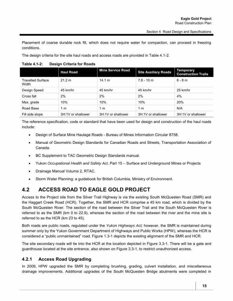
The design criteria for the site haul roads and access roads are provided in Table 4.1-2.
Table 4.1-2: Design Criteria for Roads Haul Road Mine Service Road Site Auxiliary Roads Temporary
Construction Trails
Travelled Surface Width
21.2 m 14.1 m 7.8 - 10 m 6 - 8 m
Design Speed 45 km/hr 45 km/hr 45 km/hr 25 km/hr
Cross fall 2% 2% 2% 4%
Max. grade 10% 10% 10% 20%
Road Base 1 m 1 m 1 m N/A
Fill side slope 3H:1V or shallower 3H:1V or shallower 3H:1V or shallower 3H:1V or shallower
The reference specification, code or standard that have been used for design and construction of the haul roads include:
Design of Surface Mine Haulage Roads - Bureau of Mines Information Circular 8758.
Manual of Geometric Design Standards for Canadian Roads and Streets, Transportation Association of Canada.
BC Supplement to TAC Geometric Design Standards manual.
Yukon Occupational Health and Safety Act, Part 15 – Surface and Underground Mines or Projects
Drainage Manual Volume 2, RTAC.
Storm Water Planning: a guidebook for British Columbia, Ministry of Environment.
4.2 ACCESS ROAD TO EAGLE GOLD PROJECT
Access to the Project site from the Silver Trail Highway is via the existing South McQuesten Road (SMR) and the Haggart Creek Road (HCR). Together, the SMR and HCR comprise a 45 km road, which is divided by the South McQuesten River. The section of the road between the Silver Trail and the South McQuesten River is referred to as the SMR (km 0 to 22.9), whereas the section of the road between the river and the mine site is referred to as the HCR (km 23 to 45).
Both roads are public roads, regulated under the Yukon Highways Act; however, the SMR is maintained during summer only by the Yukon Government Department of Highways and Public Works (HPW), whereas the HCR is considered a “public unmaintained” road. Figure 1.3-1 depicts the existing alignment of the SMR and HCR.
The site secondary roads will tie into the HCR at the location depicted in Figure 3.3-1. There will be a gate and guardhouse located at the site entrance, also shown on Figure 3.3-1, to restrict unauthorized access.
4.2.1 Access Road Upgrading In 2009, HPW upgraded the SMR by completing brushing, grading, culvert installation, and miscellaneous drainage improvements. Additional upgrades of the South McQuesten Bridge abutments were completed in

Eagle Gold Project Road Construction Plan
Section 4 Road Design and Specifications
16
August 2010. In August 2013, HPW completed upgrades to the Haldane Bridge which is now compliant with standard Yukon highway specifications for bridges.
It is anticipated that further upgrades to the South McQuesten Bridge will be completed by HPW.
Maintenance of the HCR is currently being completed by SGC independently of the Project to support year round exploration activities and is undertaken in accordance with existing permits.
The following upgrades are proposed for the HCR in support of the Project and will be conducted in accordance with permit terms provided by HPW and best management practices:
Upgrade from the existing one to two lane (depending on location) unimproved resource road to a two-way single-lane radio controlled resource access road utilizing the existing grade
Drainage improvements
Watercourse crossing upgrades/construction
Construction of a parking area at the South McQuesten River
Construction of pullouts approximately 500 to 1,000 m to allow vehicles moving in opposite directions to pass each other and for vehicles to stop if necessary
Signage in the parking area to describe road use protocol for drivers accessing the mine site as well as for the general public
Signage along the road, including kilometer markers visible from both directions and speed limit signs.
SGC will implement the following to maximize road and transport safety:
Work with the Department of Highways and Public Works to ensure both public and private portions of the access road are properly maintained and upgraded as required
Enforce speed limits for all Project vehicles
Ensure trucking/hauling contractors have appropriate driver training, radio contact capabilities, vehicle maintenance requirements, and spill response capabilities
Ensure all hazardous materials are transported and handled in accordance with the Transportation of
Dangerous Goods Act and Regulations
Require bulk carriers to carry two-way radios to communicate with the mine site
Identify wildlife migration corridors and crossings along the road and provide signage in high risk areas
Plow wildlife crossing and escape points in the access road snow banks (i.e. 0.5m or less at regular intervals)
Watercourse Crossings
Three watercourse crossings on the site access road have been identified as areas where modifications may be required. These modifications will improve road safety, particularly during extreme winter conditions, by ensuring that anticipated vehicle and equipment loads required to support the Project can safely access the site.

Eagle Gold Project Road Construction Plan
Section 4 Road Design and Specifications
17
Watercourse Crossing 1 - South McQuesten Bridge Km 23+000
The South McQuesten Bridge is a one lane wide 27.5 m long single span Bailey type bridge with steel bridge girders and timber decking. In 2009, an assessment by HPW was undertaken and the bridge substructure was found to be in poor condition and required repair to maintain a safe crossing. HPW completed the replacement of the bridge abutments and deck, raised the approach and lengthened the bridge to address the structural concerns with the substructure and deck. The rehabilitation work undertaken by HPW did not replace the bridge superstructure and as such, the design live load was not significantly altered. The structure is considered appropriate for the current level of activity but a more robust structure will be required to support the traffic volumes and loads anticipated during the construction and operations phases of the Eagle Gold Project.
To provide safe access during Construction, it is anticipated that further upgrades to the South McQuesten Bridge will be completed by HPW. All work required to support this temporary upgrade method can be completed within the existing South McQuesten Road Right-of-Way, will not impact the navigability of the watercourse, and will not require instream works or riparian vegetation clearing.
Existing HPW authorizations for maintenance activities on the South McQuesten Bridge are sufficient to upgrade the bridge superstructure to standard highways loads. SGC will continue to work with HPW to establish when work can be undertaken to upgrade the bridge superstructure to meet standard Yukon bridge load requirements.
Watercourse Crossing 2 - Swede Creek Crossing Km 32+650
The current crossing at Swede Creek utilizes a corrugated steel pipe (CSP) to convey the flows of Swede Creek into Haggart Creek. The existing CSP is short, resulting in a narrow driving surface and sloughing of the embankment material into both Swede Creek and Haggart Creek. An initial hydrological analysis has indicated that the diameter of the CSP does not meet design standards and is insufficient for safely conveying the 1:100 year flood event.
On April 14, 2011, Victoria Gold Corp. was issued a positive Decision Document for YESAB Project Number 2010-0226 relating to the ongoing exploration work and supporting activities on the Dublin Gulch Property. The scope of the project assessed included the upgrade of the Swede Creek Crossing to allow the installation of properly sized culvert. Approvals pursuant to the Navigable Waters Protection Act and Regulations, the Waters
Act and Regulations, the Fisheries Act, and the Highways Act and Regulations to enable the work to take place will be sought prior to or during the construction phase of the Project.
Watercourse Crossing 3 - Haggart Creek Crossing Km 41+750
The current crossing at Haggart Creek consists of two CSPs, which convey the flows of Haggart Creek under the road surface. The crossing is well armoured with riprap and under normal flow conditions is adequate for ongoing use during the construction and operations phase of the project. An initial hydrological analysis has indicated that the two CSPs are not sufficient to safely convey the 1:100 year flood event; however, the crossing itself would likely withstand a flood event. Vehicle crossings may be restricted during a flood event and as such, alternative options for upgrading the crossing are being investigated.
The upgrade of the Haggart Creek Crossing to include an overflow culvert constructed in the dry season was assessed under YESAB Project Number 2010-0226 relating to the ongoing exploration work and supporting activities on the Dublin Gulch Property. SGC is continuing to assess if an upgrade is required to support the Project and, if upgrades are deemed necessary, approvals pursuant to the Navigable Waters Protection Act and

Eagle Gold Project Road Construction Plan
Section 4 Road Design and Specifications
18
Regulations, the Waters Act and Regulations, the Fisheries Act, and the Highways Act and Regulations to enable the work to take place will be sought.
Realignment
The original road construction resulted in stretches of the HCR having steep slopes both above and below the road grade. These areas of the HCR will be modified such that the high side is pulled down to provide sufficient width for ditching, and where possible, pullouts. Where suitable, the pulled down material will be used as fill.
Radio Control One-lane Access Road Upgrades
The HCR is anticipated to become a two-way one-lane radio controlled access road. Currently the average width of the HCR is greater than a single lane but less than a standard two-lane road in most locations. After upgrade, the width of the HCR will effectively be 5 m throughout. The 5 m width will include a single 3 m wide travelled road lane with two 1 m wide shoulders. The design considered specific geometric parameters and Transportation Association of Canada (TAC) design standards for Low Volume Roads (LVR 50), as well as acceptable engineering practices for two-way one-lane access roads.
South McQuesten Parking Area
During community engagement for the environmental assessment, local residents and members of the FNNND identified the need for a parking area at the South McQuesten Bridge that could accommodate five to six vehicles and be used for vehicle and trailer parking while locals access the river. An area on the north side of the South McQuesten River and the west side of the SMR will be cleared, filled and graded to provide the parking area. Construction of the South McQuesten parking area will be conducted under Work within a Right-of-Way permit issued by HPW but will, where possible, avoid impacts to riparian vegetation within 30m of the high water mark and will follow the Best Management Practices described in Section 8 of this Plan.
4.2.2 Construction Staging Areas Construction staging areas will be required to support the upgrade of the HCR.
Three locations have been identified for staging/laydown areas. Each staging area is delineated on Figure 4.2-1. The proposed staging areas include:
Station 22+950—this staging area is located on the south side of the South McQuesten River and the west side of the SMR. This area will be re-graded and utilized as a parking area after completion of the road upgrades.
Station 32+400—this staging area is located south of Secret Creek adjacent to the HCR. This area is currently void of vegetation and has been used in the past by placer miners as a camp.
Station 41+700—this staging area is located north of where the HCR crosses Haggart Creek on the east side of the HCR. This area has been extensively placer mined in the past and has many cleared areas.
4.2.3 Traffic Volume During construction, increased vehicle and truck traffic will be required for the Project on the SMR and HCR. The largest vehicles will be B-Train vehicles, trucks with long loads (steel members, crane components), and

Eagle Gold Project Road Construction Plan
Section 4 Road Design and Specifications
19
trucks with wide loads (truck boxes, tanks, pre-fabricated camp modules). Loads will be adjusted for seasonal load restrictions, and volumes would coincide with construction and operational needs.
Estimated traffic volume during construction is:
2,500 total semi-trailer round-trips; and
7,500 to 10,000 total pickup truck (<5 tonne truck) round-trips (10 to 20 pickup truck round-trips per day on average during peak construction).
10 passenger car, pickup trucks, or buses per day during peak construction.
Estimated traffic volume during operations:
Crew shift changes are expected to occur approximately every two weeks. Personnel will travel from Mayo to the mine site by bus. This will involve approximately 100 – 120 bus roundtrips per year; and
Total truckloads are estimated at 3,000 trucks per year (round-trips). As with the estimate for the construction phase, these numbers do not account for potential seasonal load limits, which would determine potential truck size and load types.
4.2.4 Construction Control Measures SGC will implement the following measures to control soil erosion and disturbance from road construction activities:
Minimize the extent of clearing, grubbing, and grading
Restrict vehicle and construction traffic in the vicinity of water courses to existing roads, and restrict crossing to existing bridges where possible, using appropriate temporary crossing methods where needed (e.g. temporary bridges and/or ice bridges)
Flag environmentally sensitive areas before clearing and construction begins
Re-vegetate where soil stabilization and erosion control is required
Protect stockpiles from erosion with tarps, sumps, or berms
Time construction activities to avoid key fish migration periods and high risk weather and flow
Minimize the time that in-stream works occur
Implement a rigorous erosion and sediment control program
4.2.5 Operational Access Control All access to the mine site will be controlled by a manned access gate once construction starts, and all through the operational period of the mine. Public vehicle access will not be allowed at the mine site.
Emergency response organizations that service the access road will be trained in terms of the types of materials transported and appropriate response.
Where sections of the access road require single lane alternating traffic, temporary signage, pull-outs and radio controlled measures or traffic control personnel will be employed for the safe operation of two-way traffic

Eagle Gold Project Road Construction Plan
Section 4 Road Design and Specifications
20
through the single-lane section. Prior to commencement of radio control use on the HCR, a Radio Use Policy will be established.
SGC will ensure that regular known users of the HCR (i.e. placer mining operators and Registered Trapping Concession 81 holder) and the FNNND have the means and knowledge to use the one-lane two-way radio controlled access road. This will include posting the radio frequency used for traffic control on signage at the South McQuesten River Bridge and where appropriate through communications with other road users. There will be traffic monitoring and measures to mitigate potential hazards associated with construction-related truck movements, including any oversized loads. Procedures will also be included for road maintenance requirements and monitoring.
4.2.6 Temporary and Permanent Access Closure Precautionary measures will be taken to limit access during any temporary closures, including placement of barriers, traffic control signs and gates as necessary.
The HCR will remain in place at closure. Following closure of the HLF and site facilities, the main access road within the Project footprint will be permanently closed and reclaimed. However, it is proposed that a single lane road will remain to provide access to the Potato Hills. The road will be left in a semi-permanent, deactivated condition, which will allow the road to remain passable and be environmentally stable.

SIGNATURE
DRAWING APPROVAL STATUS:
NR
ROLE NAME DATE
LEAD DISC. ENG.
ENG. MANAGER
PROJ. MANAGER
EMBODIED OR REFERENCED IN THIS DRAWING REMAIN THE PROPERTY OF HATCH.
MISUSE OF THIS DRAWING BY CLIENT, AND (B) THIS DRAWING IS CONFIDENTIAL AND ALL INTELLECTUAL PROPERTY RIGHTS
RESPONSIBILITY ARISING FROM ANY USE OF OR RELIANCE ON THIS DRAWING BY ANY THIRD PARTY OR ANY MODIFICATION OR
WITH CLIENT OR SPECIFIED ON THIS DRAWING, (A) HATCH DOES NOT ACCEPT AND DISCLAIMS ANY AND ALL LIABILITY OR
[ THE RELEVANT AGREEMENT ] BETWEEN CLIENT AND [ HATCH LTD. ] ("HATCH"). UNLESS OTHERWISE AGREED IN WRITING
THIS DRAWING WAS PREPARED FOR THE EXCLUSIVE USE OF [ NAME OF CLIENT ] ("CLIENT") AND IS ISSUED PURSUANT TO
NRDRAFTSPERSON
DESIGNER
CHECKER
DESIGN COORD.
RESP. ENG.
SCALE REVDWG. No.
mcle
63959
5/3
0/2
017
c:\prj\projectwise\m
cle
63959\p
w_idc_datasourc
e\d
0373902\H
354138-2
200-2
20-2
70-0
002.d
gn
3:5
7:5
1 P
M
DATECHK'DBYDESCRIPTION
REVISIONS
No.DRAWING No.
REFERENCE DRAWINGS
DRAWING TITLE
OR AS NOTED
8
E
D
C
B
A
87654321
A
B
C
D
E
F
1 2 3 4 5 6 7
DWG. No.
REG. PROFESSIONAL
SHEET SIZE: D
850
900
950
1000
1050
1100
1150
12001200
850
900
950
1000
1050
1100
1150
12001200
0+000
0+100
0+200
0+300
0+400
0+500
0+600
0+700
0+800
0+900
1+000
1+100
1+200
1+300
1+400
1+500
1+600
1+700
1+800
1+900
2+000
2+100
2+200
2+300
2+400
2+500
2+600
2+700
2+800
2+900
3+000
3+100
750
800
850
900
950
1000
1050
11001100
750
800
850
900
950
1000
1050
11001100
0+000
0+100
0+200
0+300
0+400
0+500
0+600
0+700
0+800
0+900
1+000
1+100
1+200
1+300
1+400
1+500
1+600
1+700
1+800
1+900
2+000
2+100
2+119
750
800
850
900
950
1000
1050
11001100
750
800
850
900
950
1000
1050
11001100
0+000
0+100
0+200
0+300
0+400
0+500
800
850
900
950
1000
1050
1100
11501150
800
850
900
950
1000
1050
1100
11501150
0+000
0+100
0+200
0+300
0+400
0+500
0+600
0+700
0+800
0+900
1+000
1+100
1+200
1+300
0 240120 180
1:6000
60 300
SCALE IN METRES
0 240120 180
1:6000
60 300
SCALE IN METRES
0 240120 180
1:6000
60 300
SCALE IN METRES
0 240120 180
1:6000
60 300
SCALE IN METRES
0 240120 180
1:6000
60 300
SCALE IN METRES
0 240120 180
1:6000
60 300
SCALE IN METRES
0 240120 180
1:6000
60 300
SCALE IN METRES
0 240120 180
1:6000
60 300
SCALE IN METRES
0 240120 180
1:6000
60 300
SCALE IN METRES
0 240120 180
1:6000
60 300
SCALE IN METRES
0 240120 180
1:6000
60 300
SCALE IN METRES
0 240120 180
1:6000
60 300
SCALE IN METRES
0 240120 180
1:6000
60 300
SCALE IN METRES
0 240120 180
1:6000
60 300
SCALE IN METRES
0 240120 180
1:6000
60 300
SCALE IN METRES
0 240120 180
1:6000
60 300
SCALE IN METRES
0 240120 180
1:6000
60 300
SCALE IN METRES
0 240120 180
1:6000
60 300
SCALE IN METRES
0 240120 180
1:6000
60 300
SCALE IN METRES
0 240120 180
1:6000
60 300
SCALE IN METRES
0 240120 180
1:6000
60 300
SCALE IN METRES
0 240120 180
1:6000
60 300
SCALE IN METRES
0 240120 180
1:6000
60 300
SCALE IN METRES
0 240120 180
1:6000
60 300
SCALE IN METRES
0 240120 180
1:6000
60 300
SCALE IN METRES
0 240120 180
1:6000
60 300
SCALE IN METRES
0 240120 180
1:6000
60 300
SCALE IN METRES
0 240120 180
1:6000
60 300
SCALE IN METRES
0 240120 180
1:6000
60 300
SCALE IN METRES
0 240120 180
1:6000
60 300
SCALE IN METRES
0 240120 180
1:6000
60 300
SCALE IN METRES
0 240120 180
1:6000
60 300
SCALE IN METRES
0 240120 180
1:6000
60 300
SCALE IN METRES
0 240120 180
1:6000
60 300
SCALE IN METRES
0 240120 180
1:6000
60 300
SCALE IN METRES
CRUSHER SERVICE ROAD PROFILECRUSHER SERVICE ROAD PROFILECRUSHER SERVICE ROAD PROFILECRUSHER SERVICE ROAD PROFILECRUSHER SERVICE ROAD PROFILECRUSHER SERVICE ROAD PROFILECRUSHER SERVICE ROAD PROFILECRUSHER SERVICE ROAD PROFILE
ROM HAUL ROAD PROFILE
ADR AUXILIARY ROAD PROFILE
LIME AUXILIARY ROAD PROFILE
OVERLAND CONVEYOR ACCESS ROAD PROFILE
AN AUXILIARY ROAD PROFILEAN AUXILIARY ROAD PROFILE HLF AUXILIARY ROAD PROFILE
750
800
850
900
950
1000
1050
11001100
750
800
850
900
950
1000
1050
11001100
0+000
0+100
0+200
0+300
0+400
0+500
0+600
0+700
0+800
0+900
1+000
1+100
1+200
1+300
1+400
1+500
1+600
1+700
1+800
1+900
2+000
800
850
900
950
1000
1050
1100
11501150
800
850
900
950
1000
1050
1100
11501150
0+000
0+100
0+200
0+300
0+400
0+500
0+600
0+700
0+800
0+900
1+000
1+100
1+200
1+300
700
750
800
850
900
950
1000
10501050
700
750
800
850
900
950
1000
10501050
0+000
0+100
0+200
0+300
0+400
0+500
0+600
0+700
0+800
0+900
1+000
1+100
1+200
1+300
1+400
1+500
1+600
1+700
1+800
1+900
CENTRELINEFG AT ROAD
CENTRELINEFG AT ROAD
CENTRELINEFG AT ROAD
CENTRELINEFG AT ROAD
CENTRELINEFG AT ROAD
CENTRELINEFG AT ROAD
CENTRELINEFG AT ROAD
A
H354138-2220-220-270-0002FEL3 Started
A. MCLEAN
D. NESJAN
OVERALL
SITE ROADS
EAGLE GOLD PROJECT
H354138-2220-220-270-0002
S. PERKINS
B. RUSTAD
B. RUSTAD
1:6000
PROFILES


!
Elsa
Haggart Creek
Haggart Creek
S. McQuesten River
S. McQuesten River
Lynx Creek
Lynx Creek
Dublin GulchDublin Gulch
Silver TrailSouth McQuesten RoadSouth McQuesten Road
Haggart Creek RoadHaggart Creek Road
South McQuestenBridge
South McQuestenBridge
Eagle GoldProject SiteEagle GoldProject Site
"
"
"Station 41+700
Station 22+950Station 22+950
Station 32+400Station 32+400
Station 41+700
450000
450000
460000
460000
470000
470000
7080
000
7090
000
7080
000
7090
000
7100
000
7100
000
EAGLE GOLD PROJECTYUKON TERRITORY
Projection: Drawn By:
Date: Figure:
Legend:
0 2.5 51.25
Kilometres
Town / Village
Project Site Outline
Road - Paved
South McQuesten Gravel Road Contour (100ft)
Haggart Creek Gravel Road
Waterbody
WatercourseRoad Construction
Staging Areas4.2-1
SSNAD83 UTM
Zone 8N
2014/05/16
Construction Staging Area

Eagle Gold Project Road Construction Plan
Section 5 Borrow Sources
26
5 BORROW SOURCES
5.1 MINE SITE HAUL AND SECONDARY ROADS
All Project site road construction will utilize local material sources produced in association with the construction of these roads. Where possible, cut-and-fill operations will be undertaken so as to provide an economical and balanced operation.
Several sources of borrow material have been identified, including the reworked materials from the existing placer tailings in the Dublin Gulch and Haggart Creek valley bottoms. These reworked materials are anticipated to provide additional borrow material for the mine site roads.
It is estimated that approximately 1.85 million m3 of fill materials are present in the Dublin Gulch and Haggart Creek valley bottoms that are potentially exploitable for use elsewhere as an engineering material. Producing engineered fills for road construction from the placer tailings will require targeted selection combined with crushing and screening.
5.2 ACCESS ROAD
Materials needed for upgrading of the HCR will be obtained from ditch cuts and side borrow cuts where these materials are usable, and from borrow pits where the cut materials are waste. Based on geotechnical evaluations conducted on the HCR, three potential borrow sources have been evaluated for the construction of pull-outs, grade improvements and for road surfacing material. The locations of these potential borrow sites are illustrated in Figure 5.1-1.
Borrow 1 – Sta. 24+800
The test pits that were excavated as part of geotechnical study and located in the vicinity of Sta. 24+800, identified material considered suitable for the proposed road upgrades. The grubbing of the surficial organic layer and the stripping of underlying fine-grained sand and silt material are required and can be expected to range from 0.3 to 1.2 m in depth. The useable material beneath was found to be clean, well-graded gravel and coarse-grained sand to at least 3.2 m from grade. Combining some of the overlying fine grained soils with the clean gravel and sand was also determined to be acceptable.
Borrow 2 – Sta. 36+300
Boreholes BH10, BH11 & BH12 advanced in this area were restricted to the alignment right of way (RoW) due to the limited access available along the north side of the road, which was identified as a possible borrow source. The material encountered in the boreholes, and that of the previously drilled boreholes, confirmed useable granular materials for the proposed roadway upgrades. However, it was noted that silt contents ranging from 15 to 30% could potentially be encountered.
Borrow 3 – Sta. 37+000
This area was originally identified as a possible borrow source based on boreholes advanced as part of geotechnical study, where sand and gravel with silt contents less than 10% were encountered. Further exploration by means of test pitting with a tracked excavator will need to be completed to confirm subsurface conditions in this area.

Eagle Gold Project Road Construction Plan
Section 5 Borrow Sources
27
The objective of the subgrade design of the HCR is to take advantage of the side-hill terrain as much as possible to minimize the hauling of embankment material and, where possible, to strategically locate side-borrows (ditch widening) and quarries. Borrow material required to complete the construction will include:
10,000 m3 of road base material for general upgrades and grade raising
10,000 m3 of base material for pullouts
1,000 m3 of culvert bedding material for culvert installation
16,000 m3 of road surfacing material
Borrow source requirements for the road are estimated at 37,000 m3 for base, bedding and road surfacing material. The identified borrow areas contain more than sufficient materials for the identified road upgrades, with approximately 350,000 – 800,000 m3 of undisturbed sand and gravel available among three undisturbed borrow areas, and an additional 100,000 – 300,000 m3 of lower quality material available in a deposit of placer tailings at Secret Creek. Some processing (i.e. crushing, screening and/or washing) may be necessary to produce the required materials.
The available borrow material is generally granular. The boulder or cobble material required will be sourced from existing, weathered placer mining spoils and therefore blasting of rock is not anticipated to be required. Geotechnically unsuitable cut material derived during road modification will be placed along the toe of constructed slopes to encourage vegetation, or used to recontour and reclaim exhausted borrow areas. Care will be taken to ensure that creek encroachment as a result of road modifications is avoided.

Haggart Creek
hoe
12289-BH04
12289-BH06
12289-BH05
McQ
South
Haggart Creek
Lynx
Snowshoe
Creek
Hag
gart
C
reek
South McQuesten River
McQuesten River
South McQuesten Road
12289-TP1712289-TP18
12289-TP19
12289-TP2012289-TP21 12289-TP22
12289-TP2312289-TP2412289-TP25 12289-TP26
12289-TP27
12289-TP28
12289-BH01
12289-BH02
12289-BH03
12289-BH04
12289-BH05
12289-BH06
12289-BH07
12289-BH08
12289-BH09
12289-BH10
12289-BH11
12289-BH12
Borrow 1
Borrow 1
Eagle GoldProject Site Eagle GoldProject Site
7101
600
459200
7099
600
457200
7097
600
7095
600
7093
600
7089
600
7087
600
7085
600
7097
600
7095
600
7093
600
7089
600
7087
600
7085
600
7091
600
455200453200451200
459200457200455200453200451200449200
EAGLE GOLD PROJECTYUKON TERRITORY
Projection: Drawn By: Date: Figure:
Legend:
0 1 20.5
KilometresScale = As Shown
69kV Transmission Line
Proposed Borrow SitesBorehole Location (Dec. 2012)
Existing Road
Previous Borehole Location (Oct. 1996) Waterbody
Previous Test Pit Location (Oct. 1996) Watercourse Boreholes and
Proposed Borrow Sites
5.1-1SSNAD83 UTM
Zone 8NXX2014/05/16X
0 500
Metres
0 10.5
Kilometres

Eagle Gold Project Road Construction Plan
Section 6 Geochemical Considerations
29
6 GEOCHEMICAL CONSIDERATIONS
SGC contracted SRK to characterize the metal leaching and acid rock drainage (ML/ARD) potential of materials that will be used as borrow sources or excavated during construction of site roads and other infrastructure. Details of the methods used to characterize borrow sources are provided in the SRK 2013 Report, Geochemical
Characterization of Proposed Excavation Areas and Borrow Sources from the Eagle Gold Project, which is summarized here.
Samples representing the excavation and borrow areas were selected for testing from a set of samples collected from test pits and drill holes in 2011 by BGC Engineering Inc. as part of the geotechnical investigation for the Project. Additional road and borrow samples were collected by SGC site staff in July 2012. Where possible, road sampling was completed at existing exposures to limit the disturbance of woodland environments. In all cases, the sampling objective was to determine the potential for ML/ARD in materials that may be used for construction purposes in the future.
SRK assessed the acid rock drainage (ARD) potential of the samples using the following criteria:
Where the total sulphur content was less than 0.02% (corresponding to an acid potential (AP) of 0.6 kg CaCO3 eq/t), the samples were classified as non-reactive.
Where the total sulphur content was greater than 0.02%, and the NP/AP ratio or TIC/AP ratio was greater than 3, the samples were classified as non-potentially acid generating (non-PAG).
Where the total sulphur content was greater than 0.02% and the NP/AP or TIC/AP ratio was between 1 and 3, the samples were classified as having an uncertain potential for ARD.
Where the total sulphur content was greater than 0.02% and the NP/AP or TIC/AP ratio was less than 1, the samples were classified as potentially acid generating (PAG).
The total sulphur cut-off of 0.02%, used to define non-reactive samples in this classification scheme is considered highly conservative, particularly given that many of these samples were surficial material that have been exposed to air and water throughout their geological history.
Detailed sample descriptions are found in SRK (2013). Table 7.1-1 provides a summary of results according to material type and ARD classification.
Table 7.1-1: ARD Classification for Each Group of Samples
Group
Number of
Samples
ARD Classification (% of Samples)
Non-Reactive S <0.02%
Non-PAG Uncertain PAG NP/AP TIC/AP NP/AP TIC/AP NP/AP TIC/AP
Site Roads 34 76% 9% 0% 12% 3% 3% 21%
Placer Tailings 19 63% 5% 16% 21% 16% 11% 5%
Excavation Areas (surficial materials) 14 57% 29% 21% 7% 21% 7% 0%
Excavation Areas (rock) 5 20% 40% 20% 20% 20% 20% 40%

Eagle Gold Project Road Construction Plan
Section 6 Geochemical Considerations
30
In total, 72 samples were collected and analyzed for this study including 34 from the proposed site roads, 19 from placer tailings and alluvium borrow sources and 19 from potential cut and fill (excavation) areas. Most of these samples (n=66) were from surficial materials, five were from meta-sedimentary bedrock, and one was from a granodiorite outcrop.
The paste pH for the samples ranged from 4.6 to 8.6 (median values of 6.6). The samples typically had low sulphur and low NP and TIC levels. This is in contrast to the characterization work from the deposit area that states NP in the form of carbonate minerals was present in modest amounts throughout the deposit area. Based on having a sulphur content of <0.02%, 65% of samples were considered non-reactive. For the remaining samples, based on NP/AP or TIC/AP ratios, 7 to 14% were PAG, 11 to 14% had an uncertain potential for ARD, and 10 to 14% were non-PAG.
The majority of these samples represent surficial materials such as soils, weathered bedrock (colluvium), or gravels (alluvium or placer tailings). These differ from blasted rock from rock quarries or mine workings because their particle surfaces have already been exposed to air and water. Therefore, whether these remain in situ or are moved to a new location, they will continue to weather and oxidize at rates comparable to current weathering rates, which are quite slow.
In addition, it is likely the sulphides present in these materials were largely encapsulated within larger gravel to cobble size particles and would be unavailable for reaction. The result of moving these materials and using them for construction is not expected to result in any change relative to their current locations. In other words, while 7 to 14% of samples are PAG, and an additional 11 to 14% are classified as having an uncertain ARD potential, these materials still pose a relatively low risk for ARD potential and are considered suitable for use as construction material.
There were five meta-sedimentary rock samples taken from proposed excavation areas, and one granodiorite sample from one existing site road. Three of the meta-sedimentary samples and the one granodiorite sample were non-reactive or non-PAG, while two of the meta-sedimentary samples were PAG by either or both NP/AP ratios and TIC/AP ratios. Although the volumes of rock that would need to be excavated within construction areas are expected to be relatively small, these results indicate excavations within the meta-sedimentary rock unit will need to be monitored for ARD potential. Monitoring methods are described in the Environmental Monitoring, Surveillance and Adaptive Management Plan (EMSAMP).
As discussed in the EMSAMP, geochemical monitoring during construction will be undertaken to identify rock or soils that possess relatively higher proportions of sulfide, and therefore could require placement and handling practices to prevent ARD and the associated release of metals into surface waters. ABA test work will be conducted on grab samples of excavated materials that will be sourced for construction. Testing will confirm that rock used as construction material will have an NP/AP ratio >3, a paste pH >5 and a total sulphur content <0.3%. Materials encountered that are not within this specification will be disposed of in the WRSAs for mixing/blending with low sulphide/neutralizing materials such that geochemical “hot spots” do not develop within the WRSAs.
The geochemical monitoring of surficial materials will consist of the following:
Visual inspection of blasted rock to ensure that anomalously high concentrations of sulphide are not present.
Grab samples representing each major excavation, with a separate bulk sample collected in each distinct geological formation encountered and/or from every 200,000 m3 material moved.

Eagle Gold Project Road Construction Plan
Section 6 Geochemical Considerations
31
The geochemical monitoring of bedrock materials will consist of the following:
Grab samples representing each major excavation, with a separate sample collected in each distinct geological formation encountered and/or from every 100,000 m3 material moved. An exception is proposed for bedrock excavated from the open pit, which has been subject to extensive characterization demonstrating a low potential for ARD. Material excavated for use in construction will be sampled at a rate of one per every 250,000 m3 of material moved.

Eagle Gold Project Road Construction Plan
Section 7 Geotechnical Testing
32
7 GEOTECHNICAL TESTING
SGC and predecessor companies involved with development of quartz mining at Dublin Gulch have engaged in numerous and extensive site investigations, which have examined subsurface conditions at the locations of proposed mine site infrastructure using a variety of field and laboratory techniques. Given the presence of discontinuous permafrost in the area, close attention was given to observing and describing frozen ground in all of these investigations, including observations of excess ice where encountered. These investigations have resulted in reasonably accurate volume estimates of borrow sources and ice-rich material throughout the Project site.
Site subsurface conditions observed at the Project site prior to 2012 have been described in several reports as follows:
Report on 1995 Geotechnical Investigations for Four Potential Heap Leach Facility Site Alternatives, First Dynasty Mines, Dublin Gulch Property. (Knight Piésold, 1996a).
Report on Feasibility Design of the Mine Waste Rock Storage Area, First Dynasty Mines, Dublin Gulch Property. (Knight Piésold, 1996b).
Field Investigation Data Report, Dublin Gulch Project, New Millennium Mining. (Sitka Corp, 1996).
Hydrogeological Characterization and Assessment, Dublin Gulch Project, New Millennium Mining. (GeoEnviro Engineering, 1996).
BGC Engineering Inc. 2009. Site Facilities Geotechnical Investigation Factual Data Report. Eagle Gold Project, Victoria Gold Corporation.
Stantec. 2011. Project Proposal for Executive Committee Review. Pursuant to the Yukon Environmental
and Socio-Economic Assessment Act. Eagle Gold Project, Victoria Gold Corp. June 2011.
BGC Engineering Inc. 2011a. 2010 Geotechnical Investigation for Mine Site Infrastructure, Factual Data Report. Eagle Gold Project, Victoria Gold Corporation.
BGC Engineering Inc. 2011b. Eagle Gold – Borrow Evaluation Report, Project Memorandum, April 21, 2011; Appendix 34 in Stantec 2011. Eagle Gold Project, Victoria Gold Corporation.
BGC Engineering Inc. 2012a. 2011 Geotechnical Investigation for Mine Site Infrastructure, Factual Data Report. Eagle Gold Project, Victoria Gold Corporation.
BGC Engineering Inc. 2012b. 2012 Geotechnical Investigation for Mine Site Infrastructure, Factual Data Report. Eagle Gold Project, prepared for Victoria Gold Corporation, December 2012.
In 2010, BGC developed a geotechnical site investigation program in support of the Feasibility Study for proposed mine site infrastructure. A total of forty-nine test pits and twenty-five drill holes were completed to characterize the overburden material and bedrock conditions. In addition, three cut slopes were logged for exposed soil and rock conditions, and core from one condemnation hole drilled by SGC was logged for geotechnical purposes.

Eagle Gold Project Road Construction Plan
Section 7 Geotechnical Testing
33
Laboratory testing was completed on selected samples for moisture content, and representative samples were also tested for Atterberg Limits and grain size analysis. Various other lab tests were also completed on bulk samples of placer tailings being considered for potential use as select fill or aggregate.
This site investigation program was conducted to investigate subsurface conditions at the crushers, the truck shop, the topsoil stockpiles and other ancillary facilities. The investigation program was conducted in June and July 2012 and the field activities involved the excavation of thirty-nine test pits, advancement of five diamond drill holes, completion of six plate load tests and mapping of five outcrops (natural exposures and existing road cuts) to characterize subsurface conditions relevant for foundation and earthworks design.
Samples were taken from select test pits and boreholes for index testing of soil and strength testing of rock. Bulk samples of placer tailings were also collected for analysis for potential use as concrete aggregate. A comprehensive range of laboratory testing has been carried out to adequately characterize the engineering properties of the onsite materials.

Eagle Gold Project Road Construction Plan
Section 8 Best Management Practices
34
8 BEST MANAGEMENT PRACTICES
A suite of mitigation measures has been prepared by SGC to minimize or avoid effects on the environment. Principal among these mitigation measures are those incorporated directly into the Project design. These include; minimizing riparian clearing, incorporating fish habitat features into the Dublin Gulch Diversion Channel design, conducting in-stream works during least risk periods, and incorporating a mine water treatment plant capable of meeting water quality guidelines for aquatic life.
In addition, best management practices will be implemented to manage effects and avoid adverse effects on fish habitat. As a final mitigation measure, fish habitat compensation will off-set any loss of habitat that occurs as a result of mine road and infrastructure construction. Dublin Gulch is the only fish-bearing watercourse that lies within the footprint of the mine. The remaining watercourses inside the perimeter of the mine footprint are non-fish bearing.
8.1 SEDIMENT AND EROSION CONTROL
All necessary sediment and erosion control mitigation measures will be in place and operational prior to road construction.
Sediment mobilization and erosion will be minimized by:
Limiting the extent of land disturbance to the practical minimum
Reducing water velocities across the ground, particularly on exposed surfaces and in areas where water concentrates
Progressively rehabilitating disturbed land and constructing drainage controls to improve the stability of rehabilitated land
Protecting natural drainages and watercourses by constructing appropriate sediment control devices such as collection and diversion ditches, sediment traps, rock energy dissipaters, and sediment basins
Installing rock riprap, channel lining, sediment filters or other suitable measures in ditches on steep gradients, as required
Restricting access to rehabilitated areas
Directing all surface runoff to the appropriate water management pond
Constructing surface drainage control to intercept surface runoff
Constructing appropriate measures (e.g., silt fences, hay bales) downslope of disturbed sites (where more permanent sediment control measures are not appropriate, or in combination with more permanent measures)
Implementing soil bioengineering techniques to contain sediment and enable disturbed surfaces to recover
Installation of temporary erosion and sediment control features or “Best Management Practices” (BMPs) will be the first step towards controlling erosion and sedimentation during construction. All temporary sediment and

Eagle Gold Project Road Construction Plan
Section 8 Best Management Practices
35
erosion control features will require regular maintenance and inspection after each significant rainfall. These temporary features will be reclaimed after achieving soil and sediment stabilization
8.2 DUST CONTROL
Dust control measures for the Project site will be implemented on a case-by-case basis to ensure that mitigation measures are effectively ensuring worker health and safety and minimizing environmental effects. Best management practices and mitigation measures to be implemented will include the following:
Minimize disturbances and manage all land clearings.
Construct haul roads with low silt content material.
Enforce low speed limits for all mobile mine equipment.
Apply water as a dust suppressant using appropriate equipment (e.g., a tanker truck with spray bars) to open surfaces and heavily used roads (in the summer months). The equipment will be kept on-site during construction and used as needed to maintain moist surfaces and suppress visible dust emissions.
Water active roads in hot, dry conditions, unless meteorological conditions (e.g., rain, frozen surfaces, etc.) are adequate to suppress dust to a degree that is equivalent to 3-hour periodic watering.
Conduct visual inspections, as required, to identify and address potential dust emissions.
Record fugitive dust suppression activities daily using a fugitive dust suppression log.
Make available the fugitive dust suppression log to Yukon regulatory authorities as required.
8.3 SITE ISOLATION
Prior to roadway construction taking place, SGC staff will flag environmental sensitive areas and wildlife habitat features (e.g., mineral licks, dens, nest trees, snags, rocky outcrops, small ponds/seepages) to determine if they can be maintained. Construction activities adjacent to watercourses will be carried out with brush mowers or chainsaws to minimize environmental damage to the greatest extent possible. In riparian areas, trees within 10 m of the ordinary high water mark will be close cut and the stumps will be left in place to ensure bank stability is retained.
8.4 CULVERT INSTALLATION
Storm water management culverts will be constructed at a number of locations to direct water beneath the roadway between road ditches and will not impact existing stream systems. During the installation of these culverts, silt fencing or other sediment control measures will be installed and properly maintained at the base of slopes for the duration of site preparation, construction, installation of riprap (if required), and revegetation to ensure sedimentation is adequately controlled.

Eagle Gold Project Road Construction Plan
Section 8 Best Management Practices
36
8.5 ENVIRONMENTAL MONITORING
SGC has developed an Environmental Monitoring and Adaptive Management Plan in support of the Project. The plan includes environmental monitoring objectives, work completed to date, methods for a variety of technical disciplines, action thresholds for observed changes to the Project environment, and adaptive management approaches to respond to observed changes.
Maintaining collection of environmental baseline data prior to and throughout the Project life will provide a continuous dataset that can be used to identify temporal trends, minimize potential uncertainties associated with missing temporal segments, and ensure the variability of baseline is well understood prior to and during the period of compliance monitoring.
8.6 DECOMMISSIONING AND CLOSURE
All roads that will not be required for access post-closure (e.g., during monitoring activities) will be reclaimed. The site will be returned to a landscape that is comparable to surrounding areas for permanent closure at the end of the life of the mine. This will involve re-grading of the road, re-sloping the topography, scarifying disturbed areas, placement of any stockpiled stripping material and re-vegetation of the site. Soil replacement for these disturbances will be to the same depth that was originally salvaged from the disturbance site; the material will be sourced from adjacent windrows or soil stockpiles.
Culverts will be removed and associated fill material will be recontoured as appropriate to re-establish natural drainage patterns and stream flows. Priority areas for reclamation and closure will include those that could result in increased sedimentation into adjacent watercourses, altering both water quality and fish habitat.
Further details on the future decommissioning and closure of roads is provided in the Decommissioning and Reclamation Plan.
Following closure of the HLF and site facilities, the main access road within the Project area, from Haggart Creek (at the confluence with Dublin Gulch) to the ADR process plant site, will be permanently closed and reclaimed. The one exception will be the road that provides access to the Potato Hills as this has been identified as an important area for traditional use. The road will be left in a semi-permanent, deactivated condition, which will allow the road to remain passable and be environmentally stable.
The remaining linear disturbances such as exploration roads, tote roads, trenches and drill sites will be progressively reclaimed during the life of the mine as they become available.