Embed Size (px)
Citation preview
EA_InspectorRelease 3.6
User GuideTM42-3013I
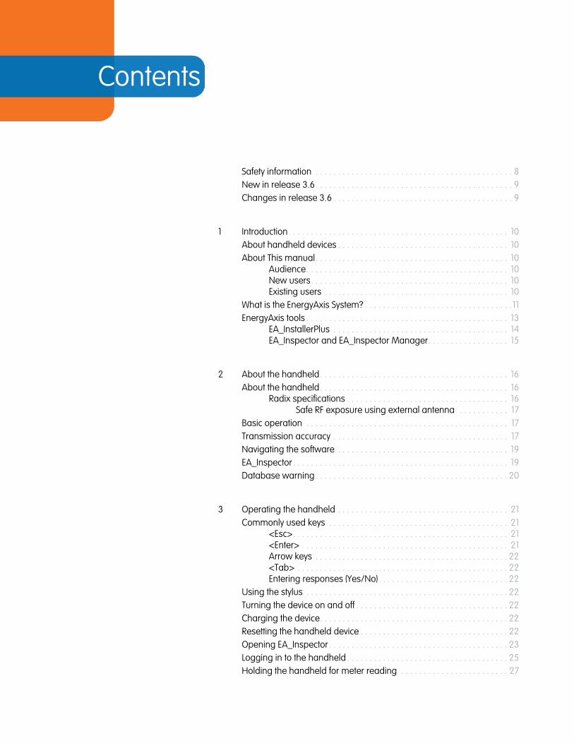
Contents
Safety information . . . . . . . . . . . . . . . . . . . . . . . . . . . . . . . . . . . . . . . . . . . . 8New in release 3.6. . . . . . . . . . . . . . . . . . . . . . . . . . . . . . . . . . . . . . . . . . . . 9Changes in release 3.6 . . . . . . . . . . . . . . . . . . . . . . . . . . . . . . . . . . . . . . . . 9
1 Introduction. . . . . . . . . . . . . . . . . . . . . . . . . . . . . . . . . . . . . . . . . . . . . . . . . 10About handheld devices . . . . . . . . . . . . . . . . . . . . . . . . . . . . . . . . . . . . . . 10About This manual. . . . . . . . . . . . . . . . . . . . . . . . . . . . . . . . . . . . . . . . . . . 10
Audience. . . . . . . . . . . . . . . . . . . . . . . . . . . . . . . . . . . . . . . . . . . . . 10New users. . . . . . . . . . . . . . . . . . . . . . . . . . . . . . . . . . . . . . . . . . . . 10Existing users . . . . . . . . . . . . . . . . . . . . . . . . . . . . . . . . . . . . . . . . . 10
What is the EnergyAxis System? . . . . . . . . . . . . . . . . . . . . . . . . . . . . . . . . .11EnergyAxis tools . . . . . . . . . . . . . . . . . . . . . . . . . . . . . . . . . . . . . . . . . . . . . 13
EA_InstallerPlus . . . . . . . . . . . . . . . . . . . . . . . . . . . . . . . . . . . . . . . 14EA_Inspector and EA_Inspector Manager. . . . . . . . . . . . . . . . . . 15
2 About the handheld. . . . . . . . . . . . . . . . . . . . . . . . . . . . . . . . . . . . . . . . . . 16About the handheld. . . . . . . . . . . . . . . . . . . . . . . . . . . . . . . . . . . . . . . . . . 16
Radix specifications . . . . . . . . . . . . . . . . . . . . . . . . . . . . . . . . . . . . 16Safe RF exposure using external antenna . . . . . . . . . . . 17
Basic operation . . . . . . . . . . . . . . . . . . . . . . . . . . . . . . . . . . . . . . . . . . . . . 17Transmission accuracy . . . . . . . . . . . . . . . . . . . . . . . . . . . . . . . . . . . . . . . 17Navigating the software . . . . . . . . . . . . . . . . . . . . . . . . . . . . . . . . . . . . . . 19EA_Inspector . . . . . . . . . . . . . . . . . . . . . . . . . . . . . . . . . . . . . . . . . . . . . . . . 19Database warning. . . . . . . . . . . . . . . . . . . . . . . . . . . . . . . . . . . . . . . . . . . 20
3 Operating the handheld . . . . . . . . . . . . . . . . . . . . . . . . . . . . . . . . . . . . . . 21Commonly used keys . . . . . . . . . . . . . . . . . . . . . . . . . . . . . . . . . . . . . . . . 21
<Esc>. . . . . . . . . . . . . . . . . . . . . . . . . . . . . . . . . . . . . . . . . . . . . . . . 21<Enter> . . . . . . . . . . . . . . . . . . . . . . . . . . . . . . . . . . . . . . . . . . . . . . 21Arrow keys . . . . . . . . . . . . . . . . . . . . . . . . . . . . . . . . . . . . . . . . . . . 22<Tab> . . . . . . . . . . . . . . . . . . . . . . . . . . . . . . . . . . . . . . . . . . . . . . . 22Entering responses (Yes/No). . . . . . . . . . . . . . . . . . . . . . . . . . . . . 22
Using the stylus . . . . . . . . . . . . . . . . . . . . . . . . . . . . . . . . . . . . . . . . . . . . . 22Turning the device on and off . . . . . . . . . . . . . . . . . . . . . . . . . . . . . . . . . . 22Charging the device. . . . . . . . . . . . . . . . . . . . . . . . . . . . . . . . . . . . . . . . . . 22Resetting the handheld device . . . . . . . . . . . . . . . . . . . . . . . . . . . . . . . . . 22Opening EA_Inspector . . . . . . . . . . . . . . . . . . . . . . . . . . . . . . . . . . . . . . . . 23Logging in to the handheld . . . . . . . . . . . . . . . . . . . . . . . . . . . . . . . . . . . . 25Holding the handheld for meter reading . . . . . . . . . . . . . . . . . . . . . . . . 27
EA_Inspector User Guide
EA_Inspector User GuideContents
3
4 About EA_Inspector software . . . . . . . . . . . . . . . . . . . . . . . . . . . . . . . . . . 28Navigating the software . . . . . . . . . . . . . . . . . . . . . . . . . . . . . . . . . . . . . . 29User privileges . . . . . . . . . . . . . . . . . . . . . . . . . . . . . . . . . . . . . . . . . . . . . . 30Saving notes and GPS data. . . . . . . . . . . . . . . . . . . . . . . . . . . . . . . . . . . . 30Exiting EA_Inspector. . . . . . . . . . . . . . . . . . . . . . . . . . . . . . . . . . . . . . . . . . 31
Exiting from the login screen. . . . . . . . . . . . . . . . . . . . . . . . . . . . . 32
5 Performing a ping test . . . . . . . . . . . . . . . . . . . . . . . . . . . . . . . . . . . . . . . . 34About ping tests . . . . . . . . . . . . . . . . . . . . . . . . . . . . . . . . . . . . . . . . . . . . . 34Accessing ping test menu. . . . . . . . . . . . . . . . . . . . . . . . . . . . . . . . . . . . . 35One shot ping test . . . . . . . . . . . . . . . . . . . . . . . . . . . . . . . . . . . . . . . . . . . 36
One shot ping of electric meter. . . . . . . . . . . . . . . . . . . . . . . . . . . 38One shot ping of a EA_Gatekeeper . . . . . . . . . . . . . . . . . 41
One shot ping of gas module . . . . . . . . . . . . . . . . . . . . . . . . . . . . 43One shot ping of a one-way water meter . . . . . . . . . . . . . . . . . . 49One shot ping of two-way water meter. . . . . . . . . . . . . . . . . . . . 51
Continuous ping test . . . . . . . . . . . . . . . . . . . . . . . . . . . . . . . . . . . . . . . . . 54Continuous ping of electric meter. . . . . . . . . . . . . . . . . . . . . . . . . 55
Continuous ping of a gatekeeper . . . . . . . . . . . . . . . . . . 57Continuous ping of gas or two-way water module . . . . . . . . . . 59
Node to node ping test . . . . . . . . . . . . . . . . . . . . . . . . . . . . . . . . . . . . . . . 61Editing continuous ping test settings . . . . . . . . . . . . . . . . . . . . . . . . . . . . 63
6 Locating a node . . . . . . . . . . . . . . . . . . . . . . . . . . . . . . . . . . . . . . . . . . . . . 64About locating nodes . . . . . . . . . . . . . . . . . . . . . . . . . . . . . . . . . . . . . . . . 64Accessing node location menu . . . . . . . . . . . . . . . . . . . . . . . . . . . . . . . . 64Registered node locator . . . . . . . . . . . . . . . . . . . . . . . . . . . . . . . . . . . . . . 65
Find all IDs. . . . . . . . . . . . . . . . . . . . . . . . . . . . . . . . . . . . . . . . . . . . 65Finding an ID. . . . . . . . . . . . . . . . . . . . . . . . . . . . . . . . . . . . . . . . . . 67
Unregistered node locator . . . . . . . . . . . . . . . . . . . . . . . . . . . . . . . . . . . . 69
7 Reading meter data. . . . . . . . . . . . . . . . . . . . . . . . . . . . . . . . . . . . . . . . . . 73Accessing Read Meter Data menu . . . . . . . . . . . . . . . . . . . . . . . . . . . . . 73Reading previous period data . . . . . . . . . . . . . . . . . . . . . . . . . . . . . . . . . 74Reading current period data. . . . . . . . . . . . . . . . . . . . . . . . . . . . . . . . . . . 75
8 Gas/Water Comms . . . . . . . . . . . . . . . . . . . . . . . . . . . . . . . . . . . . . . . . . . 77About gas and water communication. . . . . . . . . . . . . . . . . . . . . . . . . . . 77Accessing Gas/Water Comms menu . . . . . . . . . . . . . . . . . . . . . . . . . . . 77Reading gas/water comm info from an electric device. . . . . . . . . . . . . 79Reading gas/water comm info from a gas/water device . . . . . . . . . . . 80
9 Disconnecting and reconnecting meters. . . . . . . . . . . . . . . . . . . . . . . . . 81About disconnecting and reconnecting electricity meters . . . . . . . . . . . 81
REX meter service control switch status. . . . . . . . . . . . . . . . . . . . 81REX2 meter service control switch status. . . . . . . . . . . . . . . . . . . 81A3 ALPHA meter with internal polyphase service control . . . . . 82
About disconnecting and reconnecting gas meters . . . . . . . . . . . . . . . 82Accessing Connect/Disconnect menu. . . . . . . . . . . . . . . . . . . . . . . . . . . 83
EA_Inspector User GuideContents
4
Reading status of the service control switch . . . . . . . . . . . . . . . . . . . . . . 84Checking load side voltage. . . . . . . . . . . . . . . . . . . . . . . . . . . . . . . . . . . . 86Connecting an electricity meter . . . . . . . . . . . . . . . . . . . . . . . . . . . . . . . . 87Disconnecting an electricity meter . . . . . . . . . . . . . . . . . . . . . . . . . . . . . . 88Reading the state of the secondary relay . . . . . . . . . . . . . . . . . . . . . . . . 90Connecting a secondary relay . . . . . . . . . . . . . . . . . . . . . . . . . . . . . . . . . 90Disconnecting a secondary relay . . . . . . . . . . . . . . . . . . . . . . . . . . . . . . . 91Controlling a gas valve . . . . . . . . . . . . . . . . . . . . . . . . . . . . . . . . . . . . . . . 93
Gas valve privileges. . . . . . . . . . . . . . . . . . . . . . . . . . . . . . . . . . . . 93Reading a gas valve’s modules . . . . . . . . . . . . . . . . . . . . . . . . . 95
Battery alarm . . . . . . . . . . . . . . . . . . . . . . . . . . . . . . . . . . . 97Hardware failure detected . . . . . . . . . . . . . . . . . . . . . . . . 98
Opening a gas valve . . . . . . . . . . . . . . . . . . . . . . . . . . . . . . . . . . . 99Closing a gas valve . . . . . . . . . . . . . . . . . . . . . . . . . . . . . . . . . . . .101
Controlling a module’s transmitter . . . . . . . . . . . . . . . . . . . . . . . . . . . . 103Reading the current state of an RF control. . . . . . . . . . . . . . . . . 104Disabling an RF transmitter . . . . . . . . . . . . . . . . . . . . . . . . . . . . . 105Enabling an RF transmitter . . . . . . . . . . . . . . . . . . . . . . . . . . . . . 105
10 Upgrading firmware . . . . . . . . . . . . . . . . . . . . . . . . . . . . . . . . . . . . . . . . 107About upgrading firmware . . . . . . . . . . . . . . . . . . . . . . . . . . . . . . . . . . . 107
REX2 meter with EA_NIC . . . . . . . . . . . . . . . . . . . . . . . . . . . . . . . 107A3 ALPHA meter with EA_NIC . . . . . . . . . . . . . . . . . . . . . . . . . . . 108
Upgrading the EA_NIC firmware in the handheld . . . . . . . . . . . . . . . . 108Upgrading a gas or water module’s firmware. . . . . . . . . . . . . . . . . . . .110
Upgrading a gas meter’s RMD firmware . . . . . . . . . . . . . . . . . .114Upgrading a meter’s EA_NIC radio firmware . . . . . . . . . . . . . . . . . . . . .117Upgrading a REX2 meter’s firmware . . . . . . . . . . . . . . . . . . . . . . . . . . . 120Upgrading an A3 ALPHA meter’s firmware . . . . . . . . . . . . . . . . . . . . . 123Upgrading 900 MHz HAN devices . . . . . . . . . . . . . . . . . . . . . . . . . . . . 126
Upgrading a 900 MHz HAN device’s radio . . . . . . . . . . . . . . . 126Upgrading a 900 MHz HAN device firmware. . . . . . . . . . . . . . 129
11 Configuring meters . . . . . . . . . . . . . . . . . . . . . . . . . . . . . . . . . . . . . . . . . 134About HAN broadcasts . . . . . . . . . . . . . . . . . . . . . . . . . . . . . . . . . . . . . . 134Accessing HAN Broadcast menu . . . . . . . . . . . . . . . . . . . . . . . . . . . . . . 134Configuring HAN Broadcast settings . . . . . . . . . . . . . . . . . . . . . . . . . . . 136Checking the status of the meter’s HAN broadcast . . . . . . . . . . . . . . . 137Turning off the meter’s broadcast . . . . . . . . . . . . . . . . . . . . . . . . . . . . . 139Turning on the meter’s broadcast . . . . . . . . . . . . . . . . . . . . . . . . . . . . . .141Setting meter associations . . . . . . . . . . . . . . . . . . . . . . . . . . . . . . . . . . . 142Configuring water module leak settings . . . . . . . . . . . . . . . . . . . . . . . . 144Performing a demand reset on an electricity meter. . . . . . . . . . . . . . . 146
12 Managing home area network devices . . . . . . . . . . . . . . . . . . . . . . . . 149Accessing Home Area Network menu . . . . . . . . . . . . . . . . . . . . . . . . . 150ZigBee HAN device commands . . . . . . . . . . . . . . . . . . . . . . . . . . . . . . . .151
View devices. . . . . . . . . . . . . . . . . . . . . . . . . . . . . . . . . . . . . . . . . .151Viewing HAN NIC information . . . . . . . . . . . . . . . . . . . . . . . . . . 153
900 MHz HAN devices . . . . . . . . . . . . . . . . . . . . . . . . . . . . . . . . . . . . . . 153
EA_Inspector User GuideContents
5
Commissioning a 900 MHz device . . . . . . . . . . . . . . . . . . . . . . 154Reading a 900 MHz HAN device . . . . . . . . . . . . . . . . . . 155Pinging a 900 MHz HAN device . . . . . . . . . . . . . . . . . . 156
Pinging a 900 MHz device . . . . . . . . . . . . . . . . . . . . . . . . . . . . . 157Decommissioning a 900 MHz device . . . . . . . . . . . . . . . . . . . . 158
Reading a decommissioned device . . . . . . . . . . . . . . . 160Configuring a 900 MHz device. . . . . . . . . . . . . . . . . . . . . . . . . . 160
Accessing the Config 900 MHz HAN menu . . . . . . . . . 160Configuring general parameters . . . . . . . . . . . . . . . . . . .161Configuraing pricing parameters . . . . . . . . . . . . . . . . . 163Clearing pricing parameters . . . . . . . . . . . . . . . . . . . . . 165Configuring messaging parameters . . . . . . . . . . . . . . . 166
13 Configuring the handheld . . . . . . . . . . . . . . . . . . . . . . . . . . . . . . . . . . . . 169About configuring the handheld . . . . . . . . . . . . . . . . . . . . . . . . . . . . . . 169Accessing handheld configuration menu . . . . . . . . . . . . . . . . . . . . . . . 169Configuring handheld settings and utility IDs . . . . . . . . . . . . . . . . . . . . 170Configuring EA Defaults. . . . . . . . . . . . . . . . . . . . . . . . . . . . . . . . . . . . . . 173Viewing About EA_Inspector information . . . . . . . . . . . . . . . . . . . . . . . 174
A Troubleshooting . . . . . . . . . . . . . . . . . . . . . . . . . . . . . . . . . . . . . . . . . . . . 176General troubleshooting . . . . . . . . . . . . . . . . . . . . . . . . . . . . . . . . . . . . . 176Trouble connecting to EA_Inspector Manager . . . . . . . . . . . . . . . . . . . 176Communication mode errors and warning messages . . . . . . . . . . . . 176Elster contact. . . . . . . . . . . . . . . . . . . . . . . . . . . . . . . . . . . . . . . . . . . . . . . 177

EA_Inspector User Guide 6
FCC and Industry Canada compliance
Compliance statement (Part 15.19)Radix FW950 (equipped with the EnergyAxis network interface card) and Radix FW950 (equipped with the EnergyAxis network interface card and an external antenna) comply with Part 15 (ClassB), Part 90 of the FCC rules and with RSS-210 of Industry Canada.
The FCC ID's are G8JHHI03 and G8JHHI04. The Industry Canada is 4557C-HHI03.
General informationThis device complies with part 15 of the FCC Rules. Operation is subject to the following two conditions:
1. This device may not cause harmful interference, and
2. This device must accept any interference received, including interference that may cause undesired operation.
Industry Canada statementThis device complies with Industry Canada license-exempt RSS-210 standard(s). Operation is subject to the following two conditions:
1. This device may not cause harmful interference, and
2. This device must accept any interference received, including interference that may cause undesired operation.
Le présent appareil est conforme aux CNR d'Industrie Canada applicables aux appareils radio exempts de licence. L'exploitation est autorisée aux deux conditions suivantes : (1) l'appareil ne doit pas produire de brouillage, et (2) l'utilisateur de l'appareil doit accepter tout brouillage radioélectrique subi, même si le brouillage est susceptible d'en compromettre le fonctionnement.
Industry Canada antenna statement Radix FW950 (equipped with the EnergyAxis network interface card and an external antenna) incorporates an external antenna onto the handheld unit. For the handheld units please note the following statements as they relate to the external antenna on the handheld unit.
Under Industry Canada regulations, this radio transmitter may only operate using an antenna of a type and maximum (or lesser) gain approved for the transmitter by Industry Canada.
To reduce potential radio interference to other users, the antenna type and its gain should be so chosen that the equivalent isotropically radiated power (e.i.r.p.) is not more than that necessary for successful communication.
Conformément à la réglementation d'Industrie Canada, le présent émetteur radio peut fonctionner avec une antenne d'un type et d'un gain maximal (ou inférieur) approuvé pour l'émetteur par Industrie Canada.
Dans le but de réduire les risques de brouillage radioélectrique à l'intention des autres utilisateurs, il faut choisir le type d'antenne et son gain de sorte que la puissance isotrope rayonnée équivalente (p.i.r.e.) ne dépasse pas l'intensité nécessaire à l'établissement d'une communication satisfaisante.
EA_Inspector User Guide
EA_Inspector User Guide 7
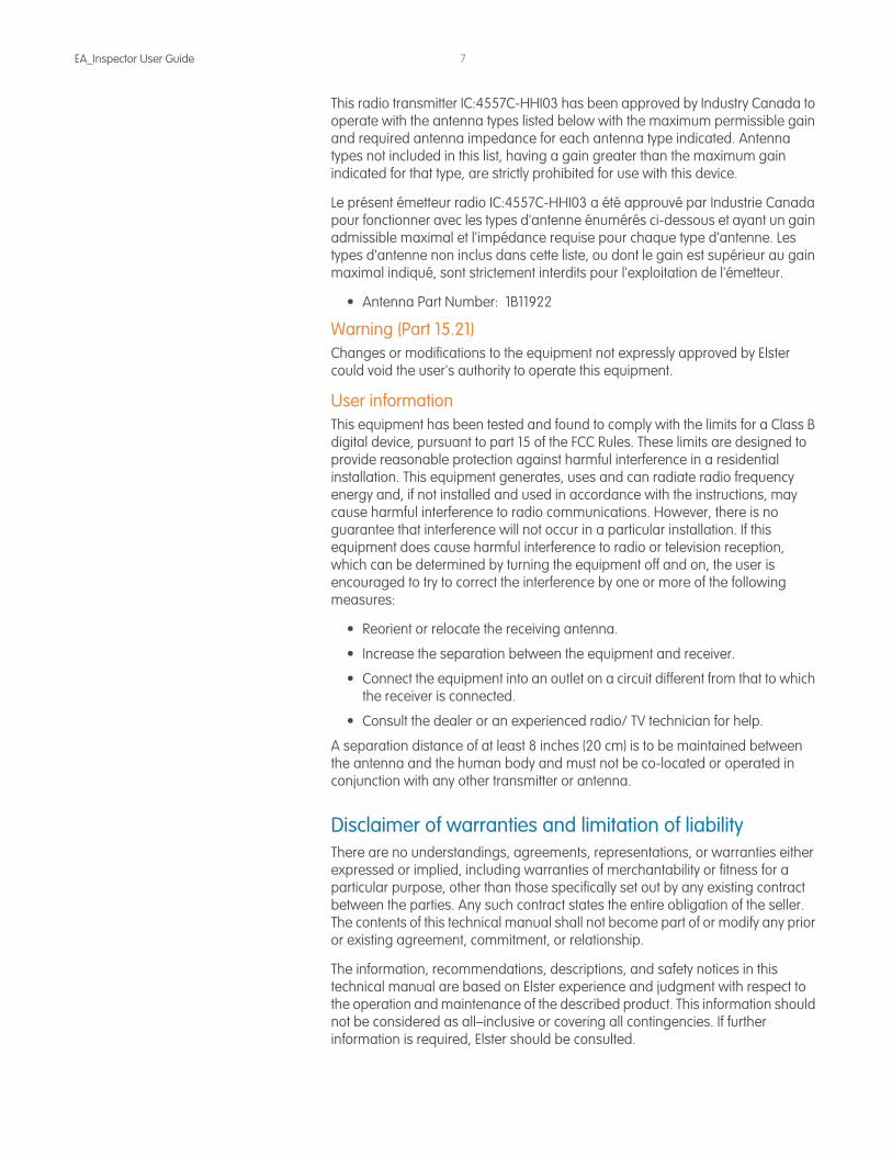
This radio transmitter IC:4557C-HHI03 has been approved by Industry Canada to operate with the antenna types listed below with the maximum permissible gain and required antenna impedance for each antenna type indicated. Antenna types not included in this list, having a gain greater than the maximum gain indicated for that type, are strictly prohibited for use with this device.
Le présent émetteur radio IC:4557C-HHI03 a été approuvé par Industrie Canada pour fonctionner avec les types d'antenne énumérés ci-dessous et ayant un gain admissible maximal et l'impédance requise pour chaque type d'antenne. Les types d'antenne non inclus dans cette liste, ou dont le gain est supérieur au gain maximal indiqué, sont strictement interdits pour l'exploitation de l'émetteur.
• Antenna Part Number: 1B11922
Warning (Part 15.21)Changes or modifications to the equipment not expressly approved by Elster could void the user's authority to operate this equipment.
User informationThis equipment has been tested and found to comply with the limits for a Class B digital device, pursuant to part 15 of the FCC Rules. These limits are designed to provide reasonable protection against harmful interference in a residential installation. This equipment generates, uses and can radiate radio frequency energy and, if not installed and used in accordance with the instructions, may cause harmful interference to radio communications. However, there is no guarantee that interference will not occur in a particular installation. If this equipment does cause harmful interference to radio or television reception, which can be determined by turning the equipment off and on, the user is encouraged to try to correct the interference by one or more of the following measures:
• Reorient or relocate the receiving antenna.
• Increase the separation between the equipment and receiver.
• Connect the equipment into an outlet on a circuit different from that to which the receiver is connected.
• Consult the dealer or an experienced radio/ TV technician for help.
A separation distance of at least 8 inches (20 cm) is to be maintained between the antenna and the human body and must not be co-located or operated in conjunction with any other transmitter or antenna.
Disclaimer of warranties and limitation of liabilityThere are no understandings, agreements, representations, or warranties either expressed or implied, including warranties of merchantability or fitness for a particular purpose, other than those specifically set out by any existing contract between the parties. Any such contract states the entire obligation of the seller. The contents of this technical manual shall not become part of or modify any prior or existing agreement, commitment, or relationship.
The information, recommendations, descriptions, and safety notices in this technical manual are based on Elster experience and judgment with respect to the operation and maintenance of the described product. This information should not be considered as all–inclusive or covering all contingencies. If further information is required, Elster should be consulted.
EA_Inspector User Guide 8
No warranties, either expressed or implied, including warranties of fitness for a particular purpose or merchantability, or warranties arising from the course of dealing or usage of trade, are made regarding the information, recommendations, descriptions, warnings, and cautions contained herein.
In no event will Elster be held responsible to the user in contract, in tort (including negligence), strict liability, or otherwise for any special, indirect, incidental, or consequential damage or loss whatsoever, including but not limited to: damage or loss of use of equipment, cost of capital, loss of profits or revenues, or claims against the user by its customers from the use of the information, recommendations, descriptions, and safety notices contained herein.
Safety information Installation, operation, and maintenance of this product can present potentially hazardous conditions (for example, high voltages) if safety procedures are not followed. To ensure that this product is used safely, it is important that you:
Review, understand, and observe all safety notices and recommendations within this manual.
Do not remove or copy individual pages from this manual, as this manual is intended for use in its entirety. If you were to remove or copy individual pages, cross references and safety notices may be overlooked, possibly resulting in damage to the equipment, personal injury, or even death.
Inform personnel involved in the installation, operation, and maintenance of the product about the safety notices and recommendations contained in this manual.
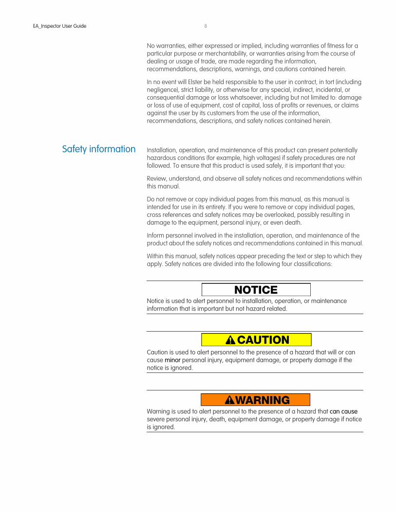
Within this manual, safety notices appear preceding the text or step to which they apply. Safety notices are divided into the following four classifications:
Notice is used to alert personnel to installation, operation, or maintenance information that is important but not hazard related.
Caution is used to alert personnel to the presence of a hazard that will or can cause minor personal injury, equipment damage, or property damage if the notice is ignored.
Warning is used to alert personnel to the presence of a hazard that can cause severe personal injury, death, equipment damage, or property damage if notice is ignored.
EA_Inspector User Guide 9
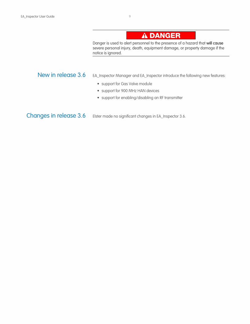
Danger is used to alert personnel to the presence of a hazard that will cause severe personal injury, death, equipment damage, or property damage if the notice is ignored.
New in release 3.6 EA_Inspector Manager and EA_Inspector introduce the following new features:
• support for Gas Valve module
• support for 900 MHz HAN devices
• support for enabling/disabling an RF transmitter
Changes in release 3.6 Elster made no significant changes in EA_Inspector 3.6.

1 INTRODUCTION
This document provides comprehensive operating instructions for the use of the EA_Inspector handheld and software.
About handheld devices Handheld devices are lightweight and easy to use handheld computers for troubleshooting EnergyAxis meter communications using touch screen technology.
About This manual This guide provides instructions for setup, operation and troubleshooting of the handheld device. It is structured for use as an adjunct to Elster system training, as well as a standalone instruction guide and reference. The screen shots shown in various illustrations may vary slightly from your handheld's display.
AudienceThis document is designed for utility industry meter readers and supervisory staff.
In order to establish appropriate levels of detail for the material, this document assumes the following:
• The user is experienced in reading meters of the type currently compatible with Elster meters and possesses all the skills necessary to conduct meter reading by conventional means.
• The user has little or no prior expertise with automated metering infrastructure (AMI) technology.
• The user is competent in the basic use of computers and software.
New usersIf you are new to Elster AMI products, or are new to AMI products in general, please take some time to go through all the sections of the user guide.
Existing usersIf you are already familiar with Elster AMI products, you will still find it helpful to go through the Introduction and detail sections to understand how the features of the handheld device work together and what information is needed to perform each feature.
EA_Inspector User Guide

EA_Inspector User GuideIntroduction
11
What is the EnergyAxisSystem?
The EnergyAxis System (Figure 1-1) is designed for residential and commercial and industrial (C&I) metering automation of electricity, gas and water. It is composed of up to three parts:
1. EnergyAxis Management System (EA_MS) that reads gatekeepers to gather meter data, analyzes RF LAN performance, and exports an XML file of all read data for importing into various enterprise systems such as billing, work order management, outage management, etc.
2. One or more 900 MHz radio frequency (RF) networks composed of an EA_Gatekeeper and up to 1024 or 2048 of the following meters:
• REX, REX2, and gREX meters equipped with an EA_NIC• optional service control switch for remote reconnection/disconnection
• optional ZigBee communications option board for home automation (REX2 meters only)
• A3 ALPHA meters with the EA_NIC (EnergyAxis network interface card)• water meters equipped with EA_Water Module (900 MHz RF radio) • gas meters equipped with EA_Gas Module (900 MHz RF radio)
3. Optional – one or more home automation networks (HAN) composed of a REX2 meter with ZigBee comm option and one or more ZigBee-enabled home area devices (HAD) - for example, programmable thermostat, in home display, or load control device.
EA_Inspector User GuideIntroduction
12
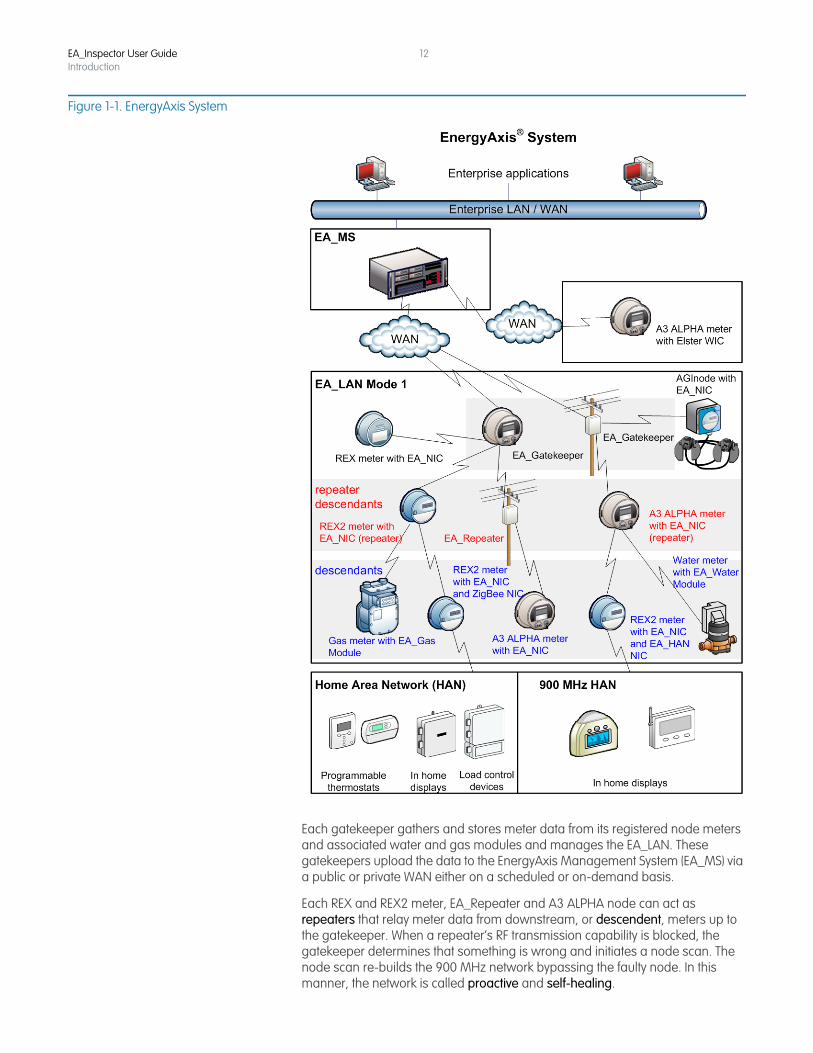
Figure 1-1. EnergyAxis System
Each gatekeeper gathers and stores meter data from its registered node meters and associated water and gas modules and manages the EA_LAN. These gatekeepers upload the data to the EnergyAxis Management System (EA_MS) via a public or private WAN either on a scheduled or on-demand basis.
Each REX and REX2 meter, EA_Repeater and A3 ALPHA node can act as repeaters that relay meter data from downstream, or descendent, meters up to the gatekeeper. When a repeater’s RF transmission capability is blocked, the gatekeeper determines that something is wrong and initiates a node scan. The node scan re-builds the 900 MHz network bypassing the faulty node. In this manner, the network is called proactive and self-healing.

EA_Inspector User GuideIntroduction
13
Figure 1-2. EnergyAxis proactive, self-healing mesh network
EnergyAxis tools Elster provides the following software tools for use with the EnergyAxis System:
• EA_Inspector
• EA_InstallerPlus
These tools use the Radix FW950 handheld. If you are currently using the Radix FW900, contact your Elster representative for details on upgrading to the FW950 handheld.
The tools require the following additional Elster software installed on a computer:
• EA_InstallerPlus requires Route Manager
• EA_Inspector requires EA_Inspector Manager
The table below details the hardware and software compatibility of EA_Inspector and EA_InstallerPlus.
Hardware Platform
EA_Inspector PI_900 Rel 1.0
EA_InstallerPlusRel 2.0Rel 1.0 Rel 2.0 Rel 3.0
Radix FW900a
EA_Inspector User GuideIntroduction
14
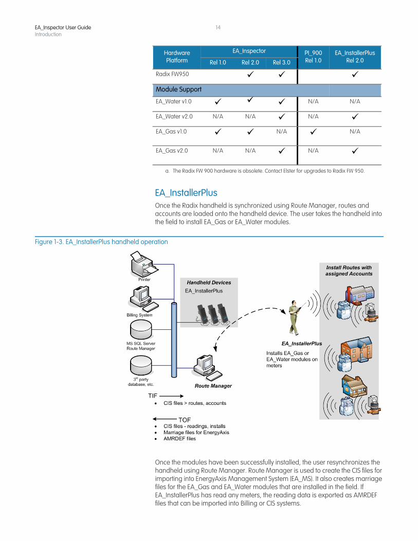
EA_InstallerPlusOnce the Radix handheld is synchronized using Route Manager, routes and accounts are loaded onto the handheld device. The user takes the handheld into the field to install EA_Gas or EA_Water modules.
Figure 1-3. EA_InstallerPlus handheld operation
Once the modules have been successfully installed, the user resynchronizes the handheld using Route Manager. Route Manager is used to create the CIS files for importing into EnergyAxis Management System (EA_MS). It also creates marriage files for the EA_Gas and EA_Water modules that are installed in the field. If EA_InstallerPlus has read any meters, the reading data is exported as AMRDEF files that can be imported into Billing or CIS systems.
Radix FW950 Module Support
EA_Water v1.0 N/A N/A
EA_Water v2.0 N/A N/A N/A EA_Gas v1.0 N/A N/A
EA_Gas v2.0 N/A N/A N/A
a. The Radix FW 900 hardware is obsolete. Contact Elster for upgrades to Radix FW 950.
Hardware Platform
EA_Inspector PI_900 Rel 1.0
EA_InstallerPlusRel 2.0Rel 1.0 Rel 2.0 Rel 3.0
EA_Inspector User GuideIntroduction
15
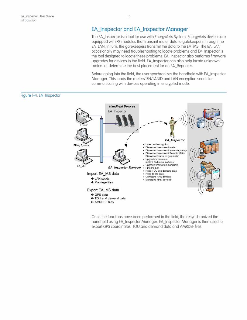
EA_Inspector and EA_Inspector ManagerThe EA_Inspector is a tool for use with EnergyAxis System. EnergyAxis devices are equipped with RF modules that transmit meter data to gatekeepers through the EA_LAN. In turn, the gatekeepers transmit the data to the EA_MS. The EA_LAN occasionally may need troubleshooting to locate problems and EA_Inspector is the tool designed to locate these problems. EA_Inspector also performs firmware upgrades for devices in the field. EA_Inspector can also help locate unknown meters or determine the best placement for an EA_Repeater.
Before going into the field, the user synchronizes the handheld with EA_Inspector Manager. This loads the meters’ SN/LANID and LAN encryption seeds for communicating with devices operating in encrypted mode.
Figure 1-4. EA_Inspector
Once the functions have been performed in the field, the resynchronized the handheld using EA_Inspector Manager. EA_Inspector Manager is then used to export GPS coordinates, TOU and demand data and AMRDEF files.

2 ABOUT THE HANDHELD
About the handheld The handheld is a Radix device that functions as the platform handheld installation tool for Elster’s EA_Gas Module and the EA_Inspector handheld. The handheld is a rugged Radix handheld computer with the EnergyAxis network interface (EA_NIC) card installed. This handheld allows field personnel to install the EA_Gas Module onto gas meters as well as perform troubleshooting tasks for EnergyAxis meter RF communications.
Figure 2-1. Radix FW950 handheld (Style No. 7S1501G002)
Radix specifications• Windows CE 5.0
• .NET Framework 1.1 or 2.0
• Marvell PXA270, 520MHz processor
• 128 MB RAM 512 MB flash drive
• 3.5” (89mm) 240 x 320 TFT 65K Color industrial grade touch screen
• 48-key ergonomic keypad with separate numeric keys
• User replaceable lithium-ion battery pack, 3 hour charge, up to 8 hours use
• EnergyAxis network interface card (EA_NIC)
• Elster software
• RF Transmitter - 900 MHz
• RF Receiver - 900 MHz
• FCC compliance: Part 90 and Part 15. The FCC ID is G8JHHI03.
• Operating temperature: -4 °F to +140 °F (-20 °C to + 60 °C)
• USB, Ethernet, serial, IPP, multiple communications ports
EA_Inspector User Guide
EA_Inspector User GuideAbout the handheld
17
• IP-67 rated (1 meter submersion)
• Elster nose cone is IP-67 rated (1 meter submersion)• MIL-STD-810F method - 1.5 meter drop onto concrete test
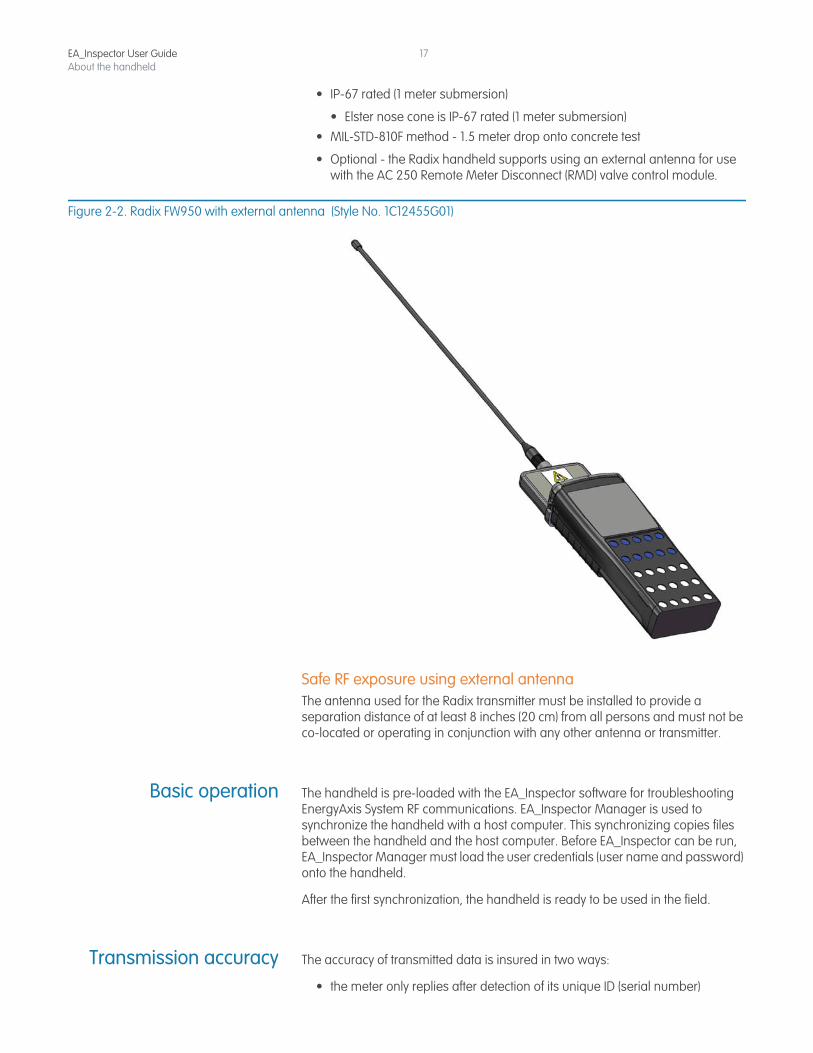
• Optional - the Radix handheld supports using an external antenna for use with the AC 250 Remote Meter Disconnect (RMD) valve control module.
Figure 2-2. Radix FW950 with external antenna (Style No. 1C12455G01)
Safe RF exposure using external antennaThe antenna used for the Radix transmitter must be installed to provide a separation distance of at least 8 inches (20 cm) from all persons and must not be co-located or operating in conjunction with any other antenna or transmitter.
Basic operation The handheld is pre-loaded with the EA_Inspector software for troubleshooting EnergyAxis System RF communications. EA_Inspector Manager is used to synchronize the handheld with a host computer. This synchronizing copies files between the handheld and the host computer. Before EA_Inspector can be run, EA_Inspector Manager must load the user credentials (user name and password) onto the handheld.
After the first synchronization, the handheld is ready to be used in the field.
Transmission accuracy The accuracy of transmitted data is insured in two ways:
• the meter only replies after detection of its unique ID (serial number)

EA_Inspector User GuideAbout the handheld
18
• the EA_NIC and module transmits an error-detection code with the meter data that is used by the handheld to confirm that the data has been received without errors.
EA_Inspector User GuideAbout the handheld
19
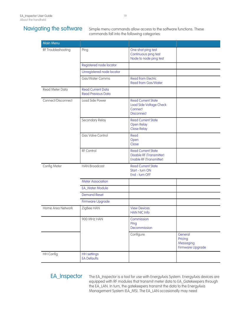
Navigating the software Simple menu commands allow access to the software functions. These commands fall into the following categories:
EA_Inspector The EA_Inspector is a tool for use with EnergyAxis System. EnergyAxis devices are equipped with RF modules that transmit meter data to EA_Gatekeepers through the EA_LAN. In turn, the gatekeepers transmit the data to the EnergyAxis Management System (EA_MS). The EA_LAN occasionally may need
Main Menu
RF Troubleshooting Ping One shot ping test Continuous ping testNode to node ping test
Registered node locator
Unregistered node locator
Gas/Water Comms Read from Electric Read from Gas/Water
Read Meter Data Read Current Data Read Previous Data
Connect/Disconnect Load Side Power Read Current State Load Side Voltage Check Connect Disconnect
Secondary Relay Read Current State Open Relay Close Relay
Gas Valve Control Read Open Close
RF Control Read Current State Disable RF (Transmitter) Enable RF (Transmitter)
Config Meter HAN Broadcast Read Current State Start - turn ON End - turn OFF
Meter Association
EA_Water Module
Demand Reset
Firmware Upgrade
Home Area Network ZigBee HAN View Devices HAN NIC Info
900 MHz HAN Commission Ping Decommission
Configure General Pricing Messaging Firmware Upgrade
HH Config HH settings EA Defaults
EA_Inspector User GuideAbout the handheld
20
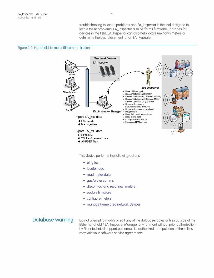
troubleshooting to locate problems and EA_Inspector is the tool designed to locate these problems. EA_Inspector also performs firmware upgrades for devices in the field. EA_Inspector can also help locate unknown meters or determine the best placement for an EA_Repeater.
Figure 2-3. Handheld-to-meter RF communication
This device performs the following actions:
• ping test
• locate node
• read meter data
• gas/water comms
• disconnect and reconnect meters
• update firmware
• configure meters
• manage home area network devices
Database warning Do not attempt to modify or edit any of the database tables or files outside of the Elster handheld / EA_Inspector Manager environment without prior authorization by Elster technical support personnel. Unauthorized manipulation of these files may void your software service agreements.
3 OPERATING THE HANDHELD
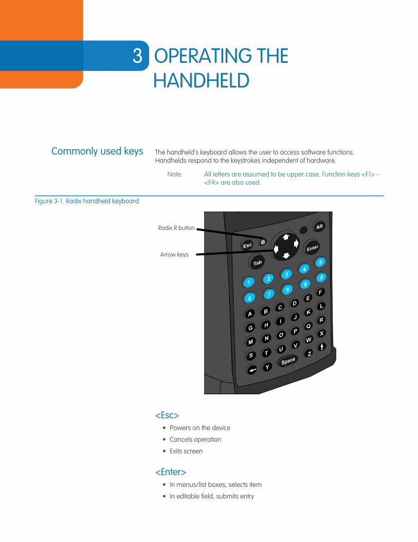
Commonly used keys The handheld’s keyboard allows the user to access software functions. Handhelds respond to the keystrokes independent of hardware.
Note: All letters are assumed to be upper case. Function keys <F1> - <F4> are also used.
Figure 3-1. Radix handheld keyboard
<Esc>• Powers on the device
• Cancels operation
• Exits screen
<Enter>• In menus/list boxes, selects item
• In editable field, submits entry
Radix R button
Arrow keys
EA_Inspector User Guide
EA_Inspector User GuideOperating the handheld
22
Arrow keysThese keys (<Up>, <Down>, <Left>, and <Right>) are used to navigate directionally in the screen.
<Tab>• Navigates between fields within the current screen (for example, messages
and search).
Entering responses (Yes/No)You respond to questions using either of the following methods:
• Tap the button Yes or No with the stylus
• Press <Y> or <N> on the keyboard
• Moving to the desired button by using left/right arrow keys and pressing <Enter> when the button is highlighted
Using the stylus Use the stylus to tap a command button or to move focus to a data entry field. If you do not have a stylus, use the tip of your fingernail (not the soft pad of your finger).
Turning the device onand off
To turn the handheld on, press and hold any key until the handheld turns on.
The handheld turns off automatically after the handheld had been idle for more than one minute off the charging cradle; the idle timeout is configurable.
Charging the device Place the handheld in its cradle to recharge the battery. The red Battery Status Light on the top right corner of the handheld will flash on and off while the battery is charging. Once that battery is fully charged, the status light will remain on.
Resetting the handhelddevice
To reset the handheld:
1. Hold down the <R> + <X> + <> keys down simultaneously for several seconds.
2. Release the keys when the screen goes blank.
3. Recalibrate the touch screen as directed.
Note: Resetting the handheld in the cradle will remove the EA_Inspector application short-cut from the desktop.
EA_Inspector User GuideOperating the handheld
23
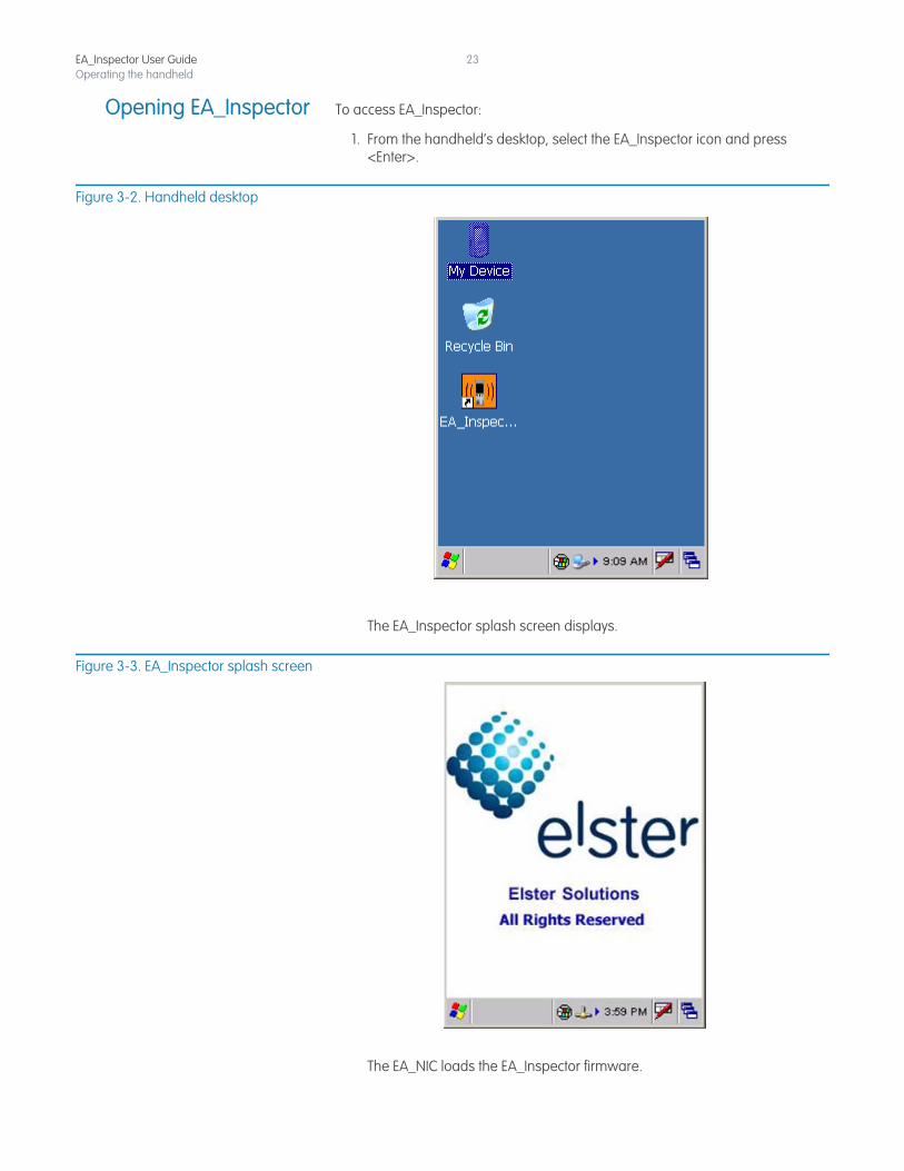
Opening EA_Inspector To access EA_Inspector:
1. From the handheld’s desktop, select the EA_Inspector icon and press <Enter>.
Figure 3-2. Handheld desktop
The EA_Inspector splash screen displays.
Figure 3-3. EA_Inspector splash screen
The EA_NIC loads the EA_Inspector firmware.
EA_Inspector User GuideOperating the handheld
24
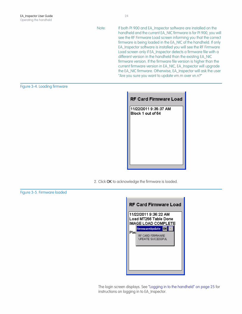
Note: If both PI 900 and EA_Inspector software are installed on the handheld and the current EA_NIC firmware is for PI 900, you will see the RF Firmware Load screen informing you that the correct firmware is being loaded in the EA_NIC of the handheld. If only EA_Inspector software is installed you will see the RF Firmware Load screen only if EA_Inspector detects a firmware file with a different version in the handheld than the existing EA_NIC firmware version. If the firmware file version is higher than the current firmware version in EA_NIC, EA_Inspector will upgrade the EA_NIC firmware. Otherwise, EA_Inspector will ask the user "Are you sure you want to update vm.m over vn.n?”
Figure 3-4. Loading firmware
2. Click OK to acknowledge the firmware is loaded.
Figure 3-5. Firmware loaded
The login screen displays. See “Logging in to the handheld” on page 25 for instructions on logging in to EA_Inspector.
EA_Inspector User GuideOperating the handheld
25
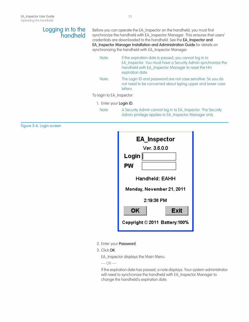
Logging in to thehandheld
Before you can operate the EA_Inspector on the handheld, you must first synchronize the handheld with EA_Inspector Manager. This ensures that users’ credentials are downloaded to the handheld. See the EA_Inspector and EA_Inspector Manager Installation and Administration Guide for details on synchronizing the handheld with EA_Inspector Manager.
Note: If the expiration date is passed, you cannot log in to EA_Inspector. You must have a Security Admin synchronize the handheld with EA_Inspector Manager to reset the HH expiration date.
Note: The Login ID and password are not case sensitive. So you do not need to be concerned about typing upper and lower case letters.
To login to EA_Inspector:
1. Enter your Login ID.
Note: A Security Admin cannot log in to EA_Inspector. The Security Admin privilege applies to EA_Inspector Manager only.
Figure 3-6. Login screen
2. Enter your Password.
3. Click OK.
EA_Inspector displays the Main Menu.
— OR —
If the expiration date has passed, a note displays. Your system administrator will need to synchronize the handheld with EA_Inspector Manager to change the handheld’s expiration date.
EA_Inspector User GuideOperating the handheld
26
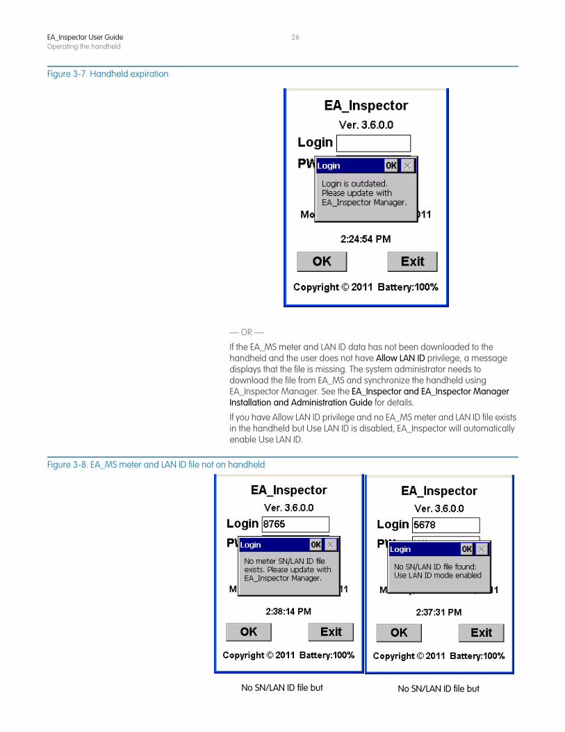
Figure 3-7. Handheld expiration
— OR —
If the EA_MS meter and LAN ID data has not been downloaded to the handheld and the user does not have Allow LAN ID privilege, a message displays that the file is missing. The system administrator needs to download the file from EA_MS and synchronize the handheld using EA_Inspector Manager. See the EA_Inspector and EA_Inspector Manager Installation and Administration Guide for details.
If you have Allow LAN ID privilege and no EA_MS meter and LAN ID file exists in the handheld but Use LAN ID is disabled, EA_Inspector will automatically enable Use LAN ID.
Figure 3-8. EA_MS meter and LAN ID file not on handheld
No SN/LAN ID file but No SN/LAN ID file but
EA_Inspector User GuideOperating the handheld
27
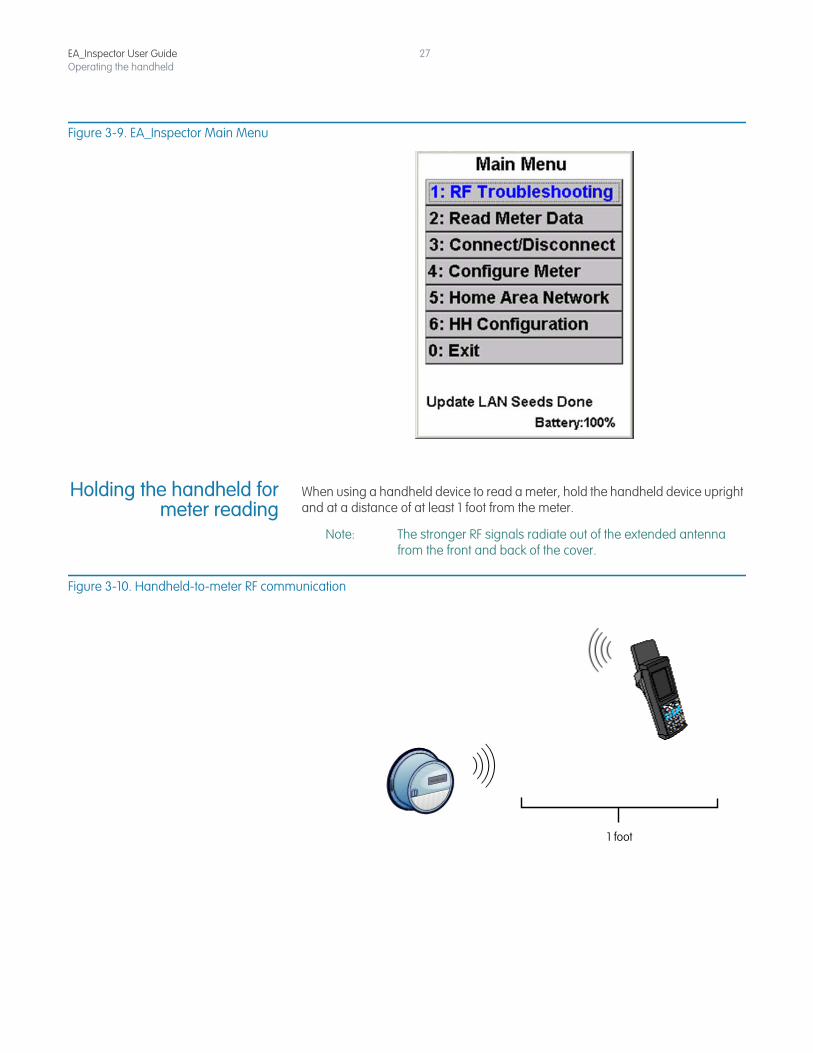
Figure 3-9. EA_Inspector Main Menu
Holding the handheld formeter reading
When using a handheld device to read a meter, hold the handheld device upright and at a distance of at least 1 foot from the meter.
Note: The stronger RF signals radiate out of the extended antenna from the front and back of the cover.
Figure 3-10. Handheld-to-meter RF communication
1 foot
4 ABOUT EA_INSPECTOR SOFTWARE
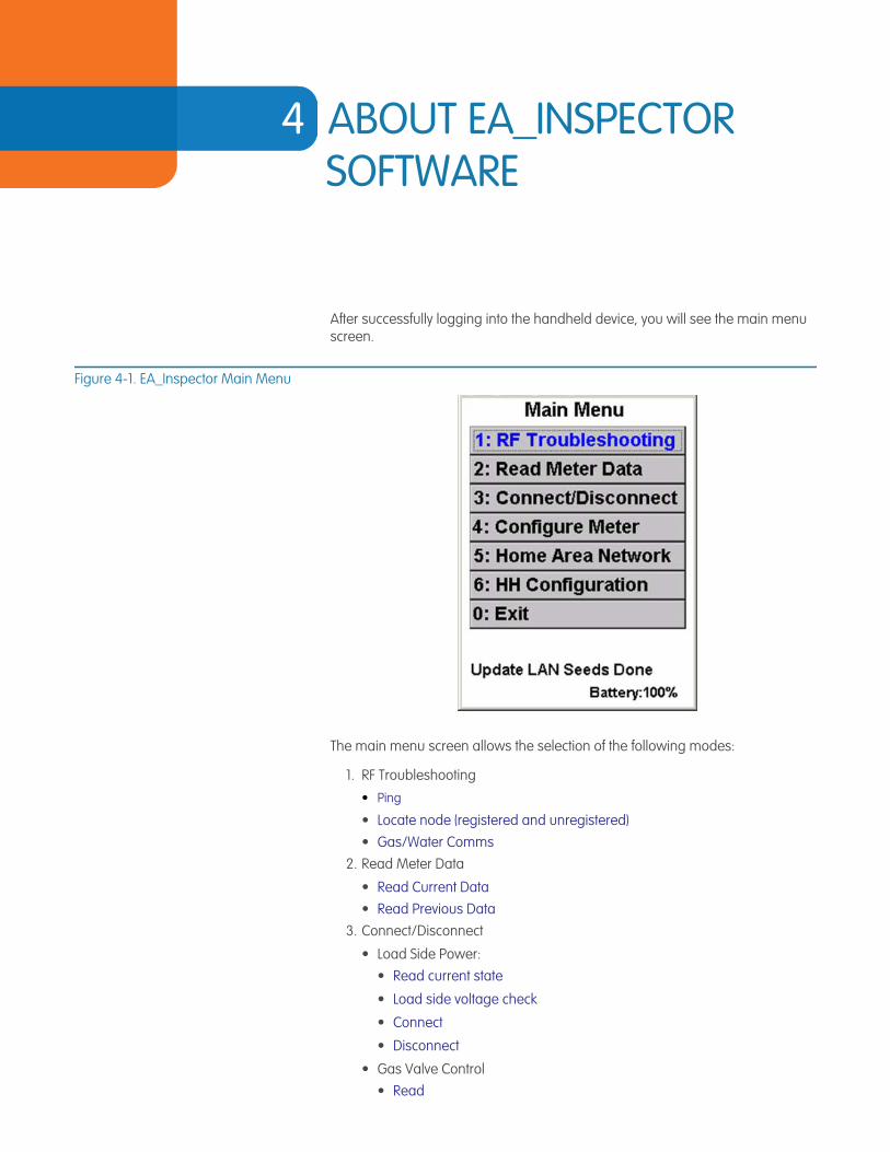
After successfully logging into the handheld device, you will see the main menu screen.
Figure 4-1. EA_Inspector Main Menu
The main menu screen allows the selection of the following modes:
1. RF Troubleshooting
• Ping
• Locate node (registered and unregistered) • Gas/Water Comms
2. Read Meter Data
• Read Current Data • Read Previous Data
3. Connect/Disconnect
• Load Side Power:• Read current state
• Load side voltage check
• Connect
• Disconnect
• Gas Valve Control • Read
EA_Inspector User Guide
EA_Inspector User GuideAbout EA_Inspector software
29
• Open
• Close
• RF Control • Read Current State
• Disable RF (Transmitter)
• Enable RF (Transmitter)
• Secondary Relay:• Read Current State
• Open Relay
• Close Relay
4. Configure Meter
• EA HAN Broadcast
• Meter Associations • EA_Water Module • Demand Reset • Firmware Upgrade
5. Home Area Network
• ZigBee HAN• Ping
• Devices
• Channels
• HAN NIC Info
• 900 MHz HAN• Commission
• Ping
• Configure
• Decommission
6. HH Configuration
• HH Settings • EA Defaults
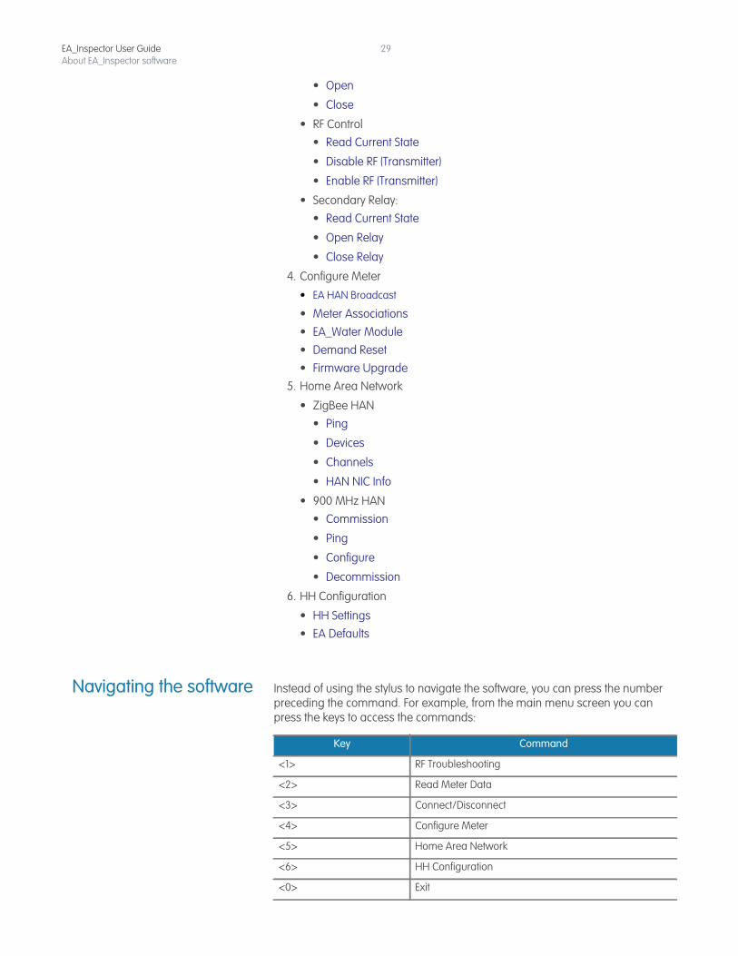
Navigating the software Instead of using the stylus to navigate the software, you can press the number preceding the command. For example, from the main menu screen you can press the keys to access the commands:
Key Command
<1> RF Troubleshooting
<2> Read Meter Data
<3> Connect/Disconnect
<4> Configure Meter
<5> Home Area Network
<6> HH Configuration
<0> Exit
EA_Inspector User GuideAbout EA_Inspector software
30
You can also use the arrow keys to navigate up and down the list of commands and then press <Enter> to execute the command.
Additionally, the first letter of each button label is an accelerator key for that function. For example, <S> for Save, <P> for Ping, <C> for Cancel, etc. <ESC> can be used for Cancel or for exiting any menu.
User privileges Depending on the privileges set by the system administrator when adding a user in EA_Inspector Manager, the user may use the LAN ID or the Serial Number of a device. Refer to the EA_Inspector and EA_Inspector Manager Installation and Administration Guide for details.
If the user has the Allow LAN ID privilege, the user may use the device’s LAN ID on data entry screens. If the user does not have the Allow LAN ID privilege, the user must enter the device’s Serial Number (S/N) on data entry screens.
Note: To use MAS 6.2 or earlier, you must have Allow LAN ID privileges.
Note: If Allow LAN ID is disabled and the EA_MS 7.0 meter name and LAN ID data have not been downloaded to the handheld, the user will not be able to use EA_Inspector. See “Downloading meter and LAN ID information” on page 33 for details.
In addition to the user having the proper privileges to Allow LAN ID, the handheld itself must be enabled to Use LAN ID. See “Configuring handheld settings and utility IDs” on page 170 for details on configuring the handheld to use LAN IDs.
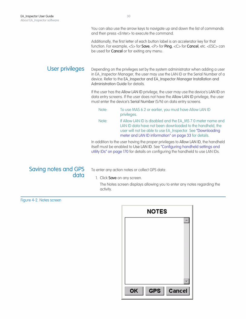
Saving notes and GPSdata
To enter any action notes or collect GPS data:
1. Click Save on any screen.
The Notes screen displays allowing you to enter any notes regarding the activity.
Figure 4-2. Notes screen
EA_Inspector User GuideAbout EA_Inspector software
31
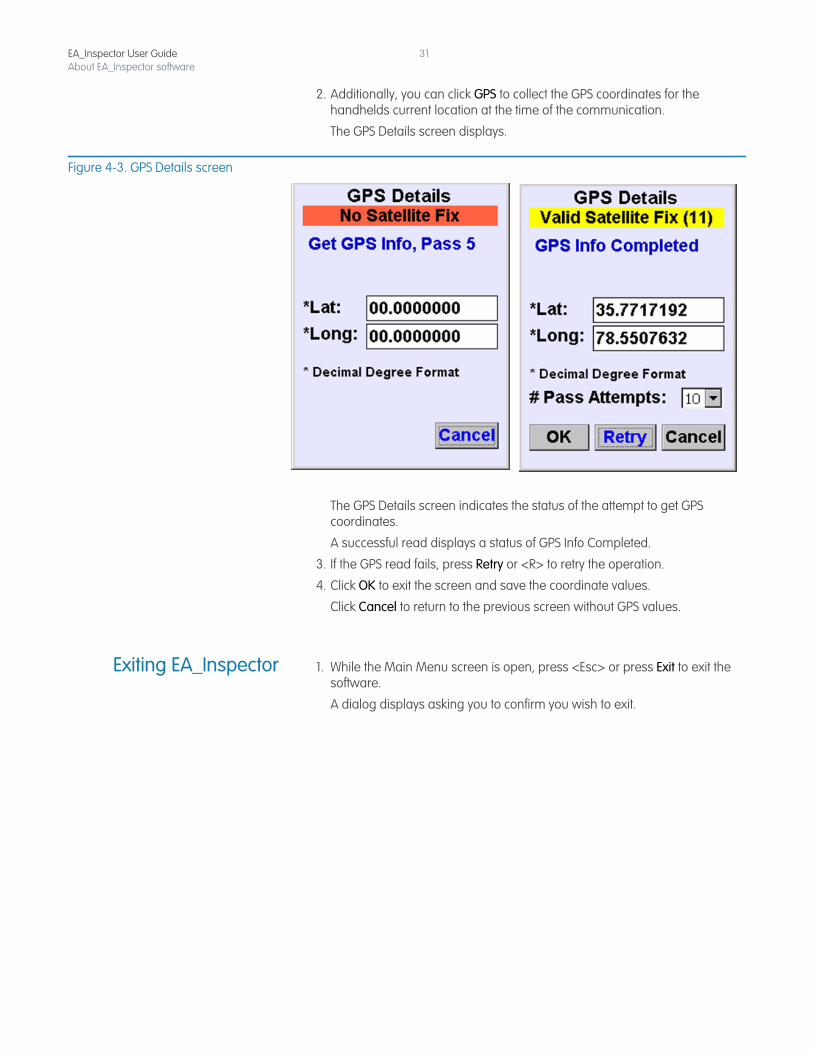
2. Additionally, you can click GPS to collect the GPS coordinates for the handhelds current location at the time of the communication.
The GPS Details screen displays.
Figure 4-3. GPS Details screen
The GPS Details screen indicates the status of the attempt to get GPS coordinates.
A successful read displays a status of GPS Info Completed.
3. If the GPS read fails, press Retry or <R> to retry the operation.
4. Click OK to exit the screen and save the coordinate values.
Click Cancel to return to the previous screen without GPS values.
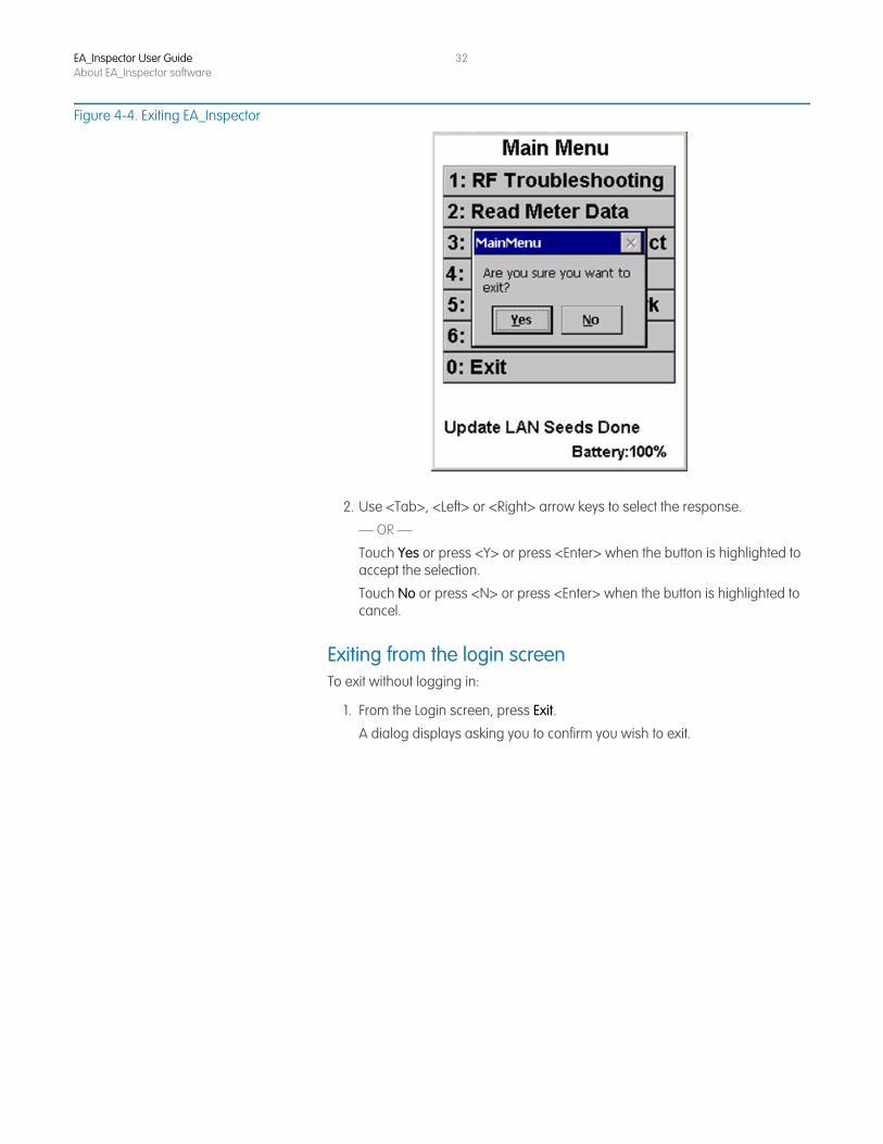
Exiting EA_Inspector 1. While the Main Menu screen is open, press <Esc> or press Exit to exit the software.
A dialog displays asking you to confirm you wish to exit.
EA_Inspector User GuideAbout EA_Inspector software
32
Figure 4-4. Exiting EA_Inspector
2. Use <Tab>, <Left> or <Right> arrow keys to select the response.
— OR —
Touch Yes or press <Y> or press <Enter> when the button is highlighted to accept the selection.
Touch No or press <N> or press <Enter> when the button is highlighted to cancel.
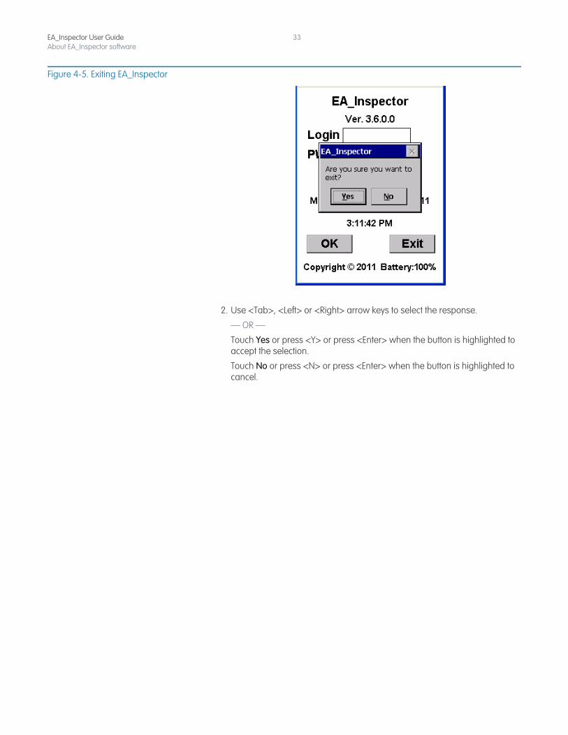
Exiting from the login screenTo exit without logging in:
1. From the Login screen, press Exit.
A dialog displays asking you to confirm you wish to exit.
EA_Inspector User GuideAbout EA_Inspector software
33
Figure 4-5. Exiting EA_Inspector
2. Use <Tab>, <Left> or <Right> arrow keys to select the response.
— OR —
Touch Yes or press <Y> or press <Enter> when the button is highlighted to accept the selection.
Touch No or press <N> or press <Enter> when the button is highlighted to cancel.

5 PERFORMING A PING TEST
About ping tests A ping test sends an RF command to an EnergyAxis RF module (EA_NIC) or meter and retrieves the devices ID and serial number. A ping test sends ten packets, receives ten packets in response and reports the average received signal strength indication (RSSI) from the ten attempts. RSSI is displayed in decibel milliWatts (dBm) except for Node to node ping test which uses the range of 0 to 7 where 0 indicates no signal and 1 indicates the best (or maximum) RSSI and 7 indicates the worst RSSI:
The continuous ping test performs multiple ping tests in sequence.
RSSI Strength (in dBm)
0 no signal
1 > -40 best
2 -40 and > -50
3 -50 and > -60
4 -60 and > -70
5 -70 and > -80
6 -80 and > -90
7 -90 worst
EA_Inspector User Guide
EA_Inspector User GuidePerforming a ping test
35
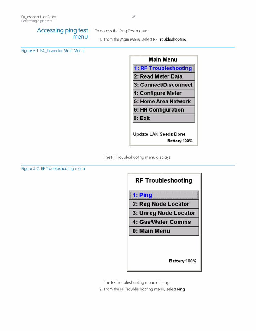
Accessing ping testmenu
To access the Ping Test menu:
1. From the Main Menu, select RF Troubleshooting.
Figure 5-1. EA_Inspector Main Menu
The RF Troubleshooting menu displays.
Figure 5-2. RF Troubleshooting menu
The RF Troubleshooting menu displays.
2. From the RF Troubleshooting menu, select Ping.
EA_Inspector User GuidePerforming a ping test
36
Figure 5-3. Ping Test menu
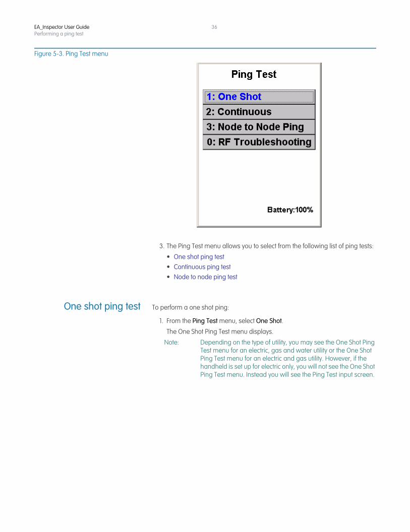
3. The Ping Test menu allows you to select from the following list of ping tests:
• One shot ping test• Continuous ping test• Node to node ping test
One shot ping test To perform a one shot ping:
1. From the Ping Test menu, select One Shot.
The One Shot Ping Test menu displays.
Note: Depending on the type of utility, you may see the One Shot Ping Test menu for an electric, gas and water utility or the One Shot Ping Test menu for an electric and gas utility. However, if the handheld is set up for electric only, you will not see the One Shot Ping Test menu. Instead you will see the Ping Test input screen.
EA_Inspector User GuidePerforming a ping test
37
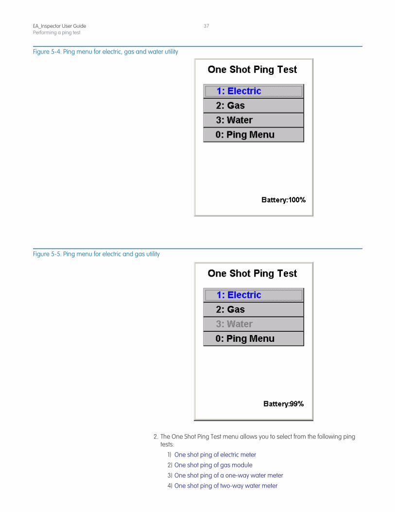
Figure 5-4. Ping menu for electric, gas and water utility
Figure 5-5. Ping menu for electric and gas utility
2. The One Shot Ping Test menu allows you to select from the following ping tests:
1) One shot ping of electric meter
2) One shot ping of gas module
3) One shot ping of a one-way water meter
4) One shot ping of two-way water meter
EA_Inspector User GuidePerforming a ping test
38
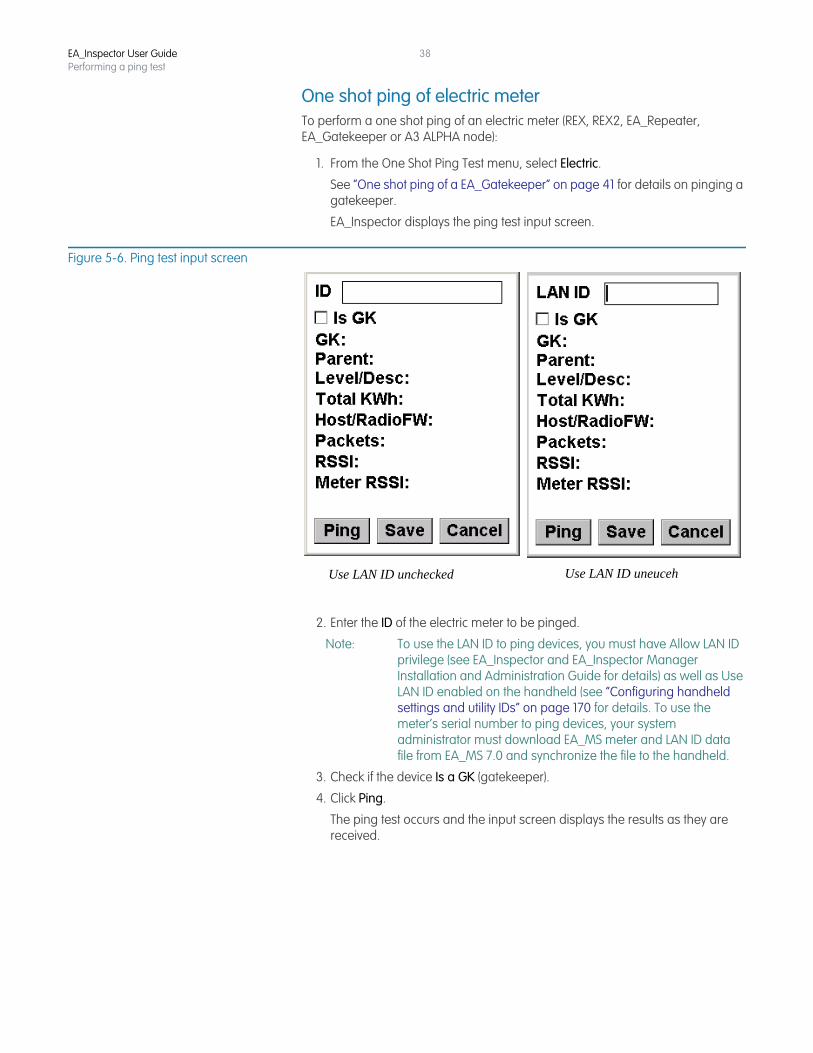
One shot ping of electric meterTo perform a one shot ping of an electric meter (REX, REX2, EA_Repeater, EA_Gatekeeper or A3 ALPHA node):
1. From the One Shot Ping Test menu, select Electric.
See “One shot ping of a EA_Gatekeeper” on page 41 for details on pinging a gatekeeper.
EA_Inspector displays the ping test input screen.
Figure 5-6. Ping test input screen
2. Enter the ID of the electric meter to be pinged.
Note: To use the LAN ID to ping devices, you must have Allow LAN ID privilege (see EA_Inspector and EA_Inspector Manager Installation and Administration Guide for details) as well as Use LAN ID enabled on the handheld (see “Configuring handheld settings and utility IDs” on page 170 for details. To use the meter’s serial number to ping devices, your system administrator must download EA_MS meter and LAN ID data file from EA_MS 7.0 and synchronize the file to the handheld.
3. Check if the device Is a GK (gatekeeper).
4. Click Ping.
The ping test occurs and the input screen displays the results as they are received.
Use LAN ID uneucehUse LAN ID unchecked
EA_Inspector User GuidePerforming a ping test
39
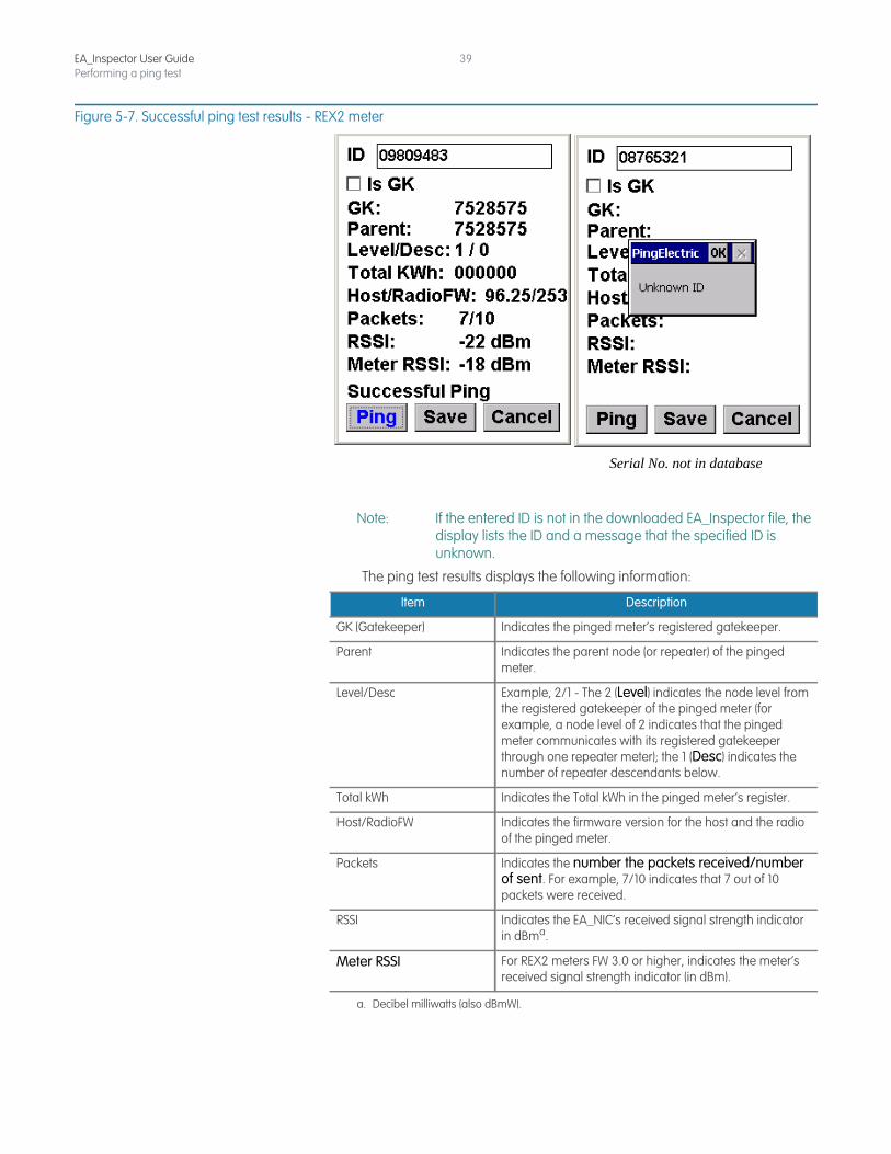
Figure 5-7. Successful ping test results - REX2 meter
Note: If the entered ID is not in the downloaded EA_Inspector file, the display lists the ID and a message that the specified ID is unknown.
The ping test results displays the following information:
Serial No. not in database
Item Description
GK (Gatekeeper) Indicates the pinged meter’s registered gatekeeper.
Parent Indicates the parent node (or repeater) of the pinged meter.
Level/Desc Example, 2/1 - The 2 (Level) indicates the node level from the registered gatekeeper of the pinged meter (for example, a node level of 2 indicates that the pinged meter communicates with its registered gatekeeper through one repeater meter); the 1 (Desc) indicates the number of repeater descendants below.
Total kWh Indicates the Total kWh in the pinged meter’s register.
Host/RadioFW Indicates the firmware version for the host and the radio of the pinged meter.
Packets Indicates the number the packets received/number of sent. For example, 7/10 indicates that 7 out of 10 packets were received.
RSSI Indicates the EA_NIC’s received signal strength indicator in dBma.
a. Decibel milliwatts (also dBmW).
Meter RSSI For REX2 meters FW 3.0 or higher, indicates the meter’s received signal strength indicator (in dBm).
EA_Inspector User GuidePerforming a ping test
40
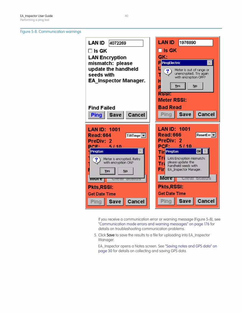
Figure 5-8. Communication warnings
If you receive a communication error or warning message [Figure 5-8], see “Communication mode errors and warning messages” on page 176 for details on troubleshooting communication problems.
5. Click Save to save the results to a file for uploading into EA_Inspector Manager.
EA_Inspector opens a Notes screen. See “Saving notes and GPS data” on page 30 for details on collecting and saving GPS data.
EA_Inspector User GuidePerforming a ping test
41
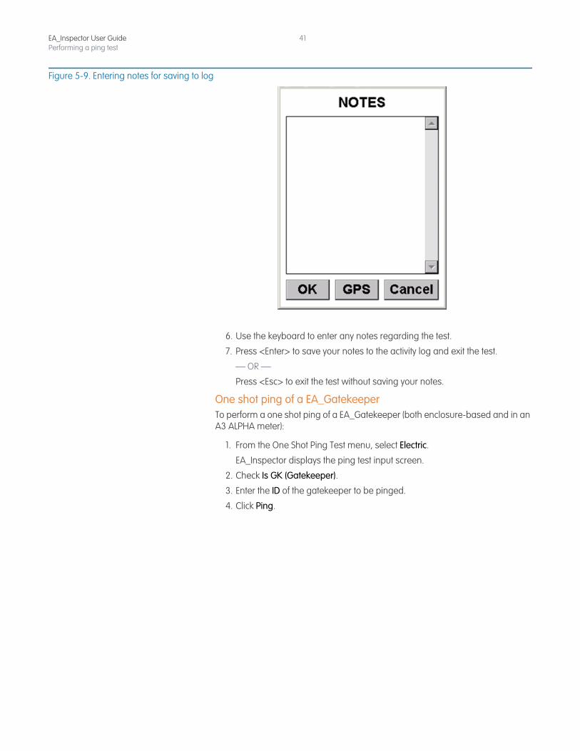
Figure 5-9. Entering notes for saving to log
6. Use the keyboard to enter any notes regarding the test.
7. Press <Enter> to save your notes to the activity log and exit the test.
— OR —
Press <Esc> to exit the test without saving your notes.
One shot ping of a EA_GatekeeperTo perform a one shot ping of a EA_Gatekeeper (both enclosure-based and in an A3 ALPHA meter):
1. From the One Shot Ping Test menu, select Electric.
EA_Inspector displays the ping test input screen.
2. Check Is GK (Gatekeeper).
3. Enter the ID of the gatekeeper to be pinged.
4. Click Ping.
EA_Inspector User GuidePerforming a ping test
42
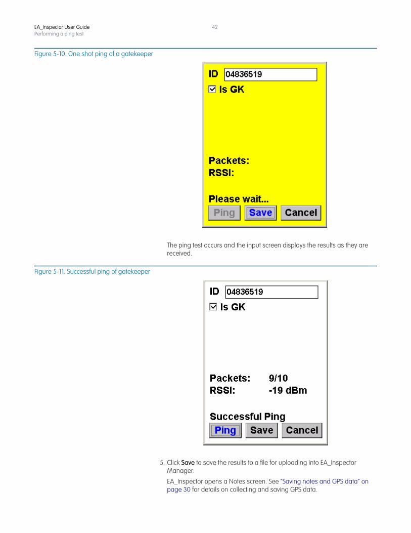
Figure 5-10. One shot ping of a gatekeeper
The ping test occurs and the input screen displays the results as they are received.
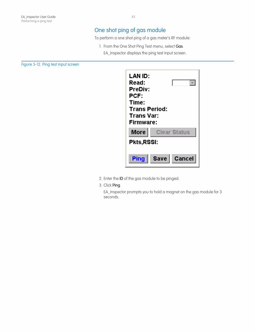
Figure 5-11. Successful ping of gatekeeper
5. Click Save to save the results to a file for uploading into EA_Inspector Manager.
EA_Inspector opens a Notes screen. See “Saving notes and GPS data” on page 30 for details on collecting and saving GPS data.
EA_Inspector User GuidePerforming a ping test
43
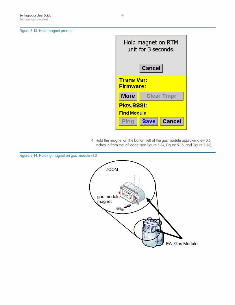
One shot ping of gas moduleTo perform a one shot ping of a gas meter’s RF module:
1. From the One Shot Ping Test menu, select Gas.
EA_Inspector displays the ping test input screen.
Figure 5-12. Ping test input screen
2. Enter the ID of the gas module to be pinged.
3. Click Ping.
EA_Inspector prompts you to hold a magnet on the gas module for 3 seconds.
EA_Inspector User GuidePerforming a ping test
44
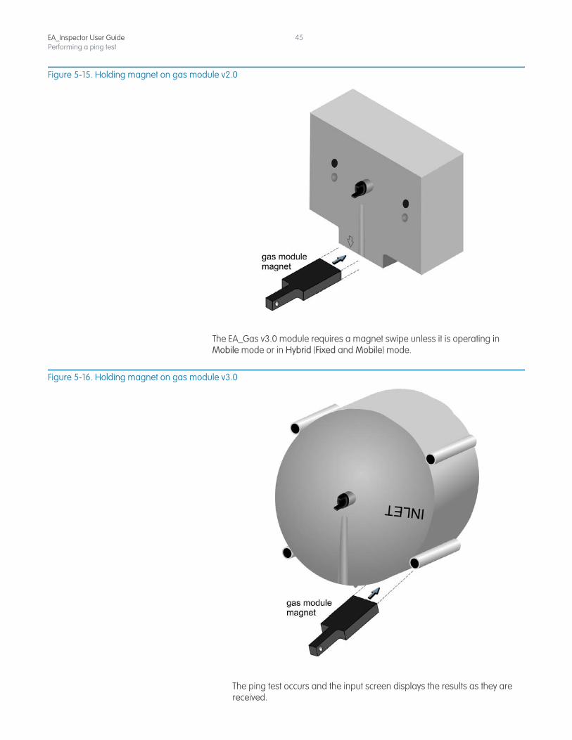
Figure 5-13. Hold magnet prompt
4. Hold the magnet on the bottom left of the gas module approximately 0.5 inches in from the left edge (see Figure 5-14, Figure 5-15, and Figure 5-16).
Figure 5-14. Holding magnet on gas module v1.0
EA_Inspector User GuidePerforming a ping test
45
Figure 5-15. Holding magnet on gas module v2.0
The EA_Gas v3.0 module requires a magnet swipe unless it is operating in Mobile mode or in Hybrid (Fixed and Mobile) mode.
Figure 5-16. Holding magnet on gas module v3.0
The ping test occurs and the input screen displays the results as they are received.
EA_Inspector User GuidePerforming a ping test
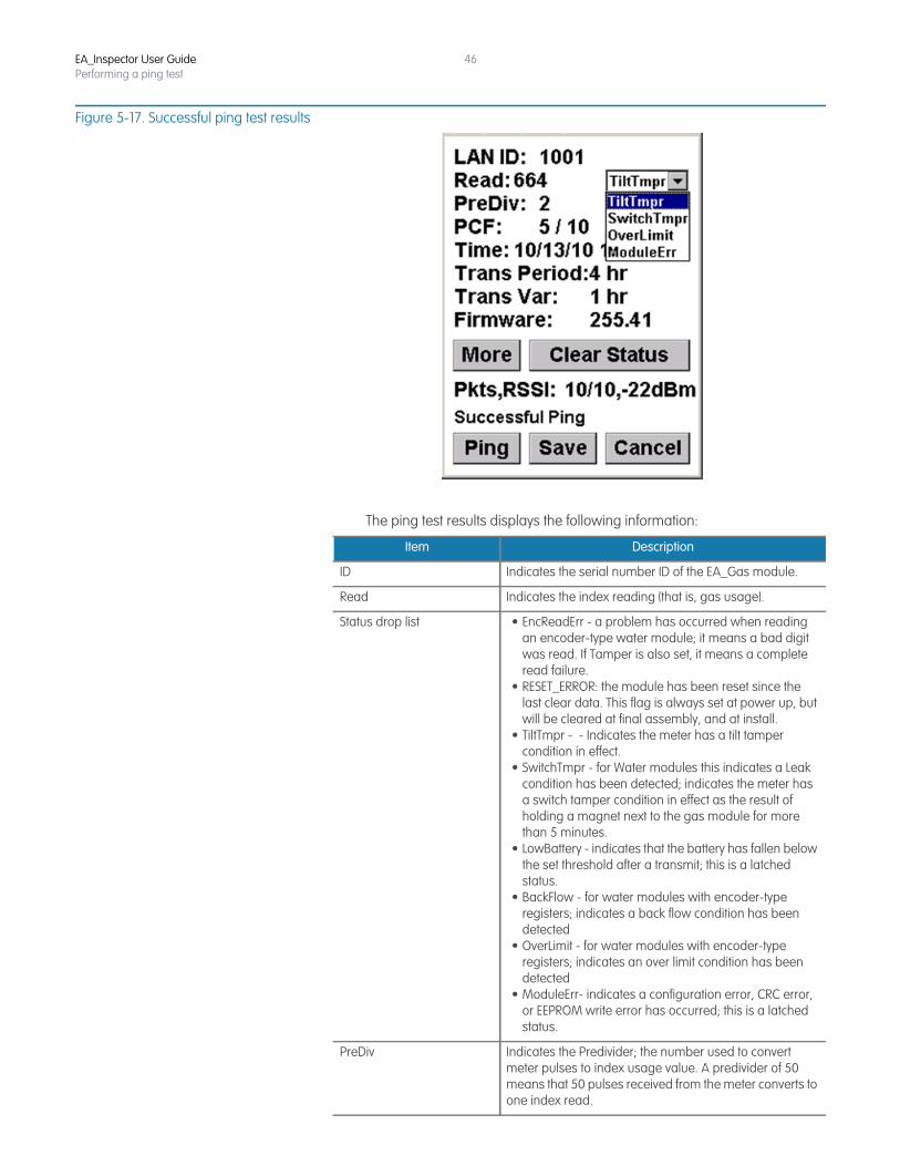
46
Figure 5-17. Successful ping test results
The ping test results displays the following information:
Item Description
ID Indicates the serial number ID of the EA_Gas module.
Read Indicates the index reading (that is, gas usage).
Status drop list • EncReadErr - a problem has occurred when reading an encoder-type water module; it means a bad digit was read. If Tamper is also set, it means a complete read failure.
• RESET_ERROR: the module has been reset since the last clear data. This flag is always set at power up, but will be cleared at final assembly, and at install.
• TiltTmpr - - Indicates the meter has a tilt tamper condition in effect.
• SwitchTmpr - for Water modules this indicates a Leak condition has been detected; indicates the meter has a switch tamper condition in effect as the result of holding a magnet next to the gas module for more than 5 minutes.
• LowBattery - indicates that the battery has fallen below the set threshold after a transmit; this is a latched status.
• BackFlow - for water modules with encoder-type registers; indicates a back flow condition has been detected
• OverLimit - for water modules with encoder-type registers; indicates an over limit condition has been detected
• ModuleErr- indicates a configuration error, CRC error, or EEPROM write error has occurred; this is a latched status.
PreDiv Indicates the Predivider; the number used to convert meter pulses to index usage value. A predivider of 50 means that 50 pulses received from the meter converts to one index read.
EA_Inspector User GuidePerforming a ping test
47
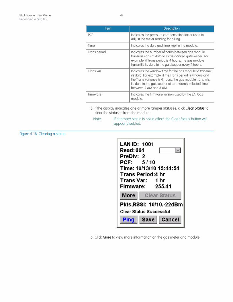
5. If the display indicates one or more tamper statuses, click Clear Status to clear the statuses from the module.
Note: If a tamper status is not in effect, the Clear Status button will appear disabled.
Figure 5-18. Clearing a status
6. Click More to view more information on the gas meter and module.
PCF Indicates the pressure compensation factor used to adjust the meter reading for billing.
Time Indicates the date and time kept in the module.
Trans period Indicates the number of hours between gas module transmissions of data to its associated gatekeeper. For example, if Trans period is 4 hours, the gas module transmits its data to the gatekeeper every 4 hours.
Trans var Indicates the window time for the gas module to transmit its data. For example, if the Trans period is 4 hours and the Trans variance is 4 hours, the gas module transmits its data to the gatekeeper at a randomly selected time between 4 AM and 8 AM.
Firmware Indicates the firmware version used by the EA_Gas module.
Item Description
EA_Inspector User GuidePerforming a ping test
48
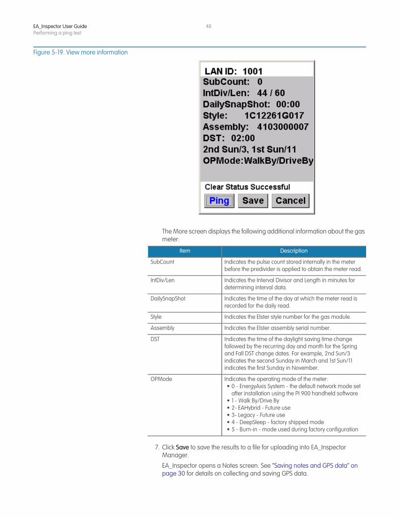
Figure 5-19. View more information
The More screen displays the following additional information about the gas meter:
7. Click Save to save the results to a file for uploading into EA_Inspector Manager.
EA_Inspector opens a Notes screen. See “Saving notes and GPS data” on page 30 for details on collecting and saving GPS data.
Item Description
SubCount Indicates the pulse count stored internally in the meter before the predivider is applied to obtain the meter read.
IntDiv/Len Indicates the Interval Divisor and Length in minutes for determining interval data.
DailySnapShot Indicates the time of the day at which the meter read is recorded for the daily read.
Style Indicates the Elster style number for the gas module.
Assembly Indicates the Elster assembly serial number.
DST Indicates the time of the daylight saving time change followed by the recurring day and month for the Spring and Fall DST change dates. For example, 2nd Sun/3 indicates the second Sunday in March and 1st Sun/11 indicates the first Sunday in November.
OPMode Indicates the operating mode of the meter:• 0 - EnergyAxis System - the default network mode set
after installation using the PI 900 handheld software• 1 - Walk By/Drive By • 2- EAHybrid - Future use• 3- Legacy - Future use• 4 - DeepSleep - factory shipped mode• 5 - Burn-in - mode used during factory configuration
EA_Inspector User GuidePerforming a ping test
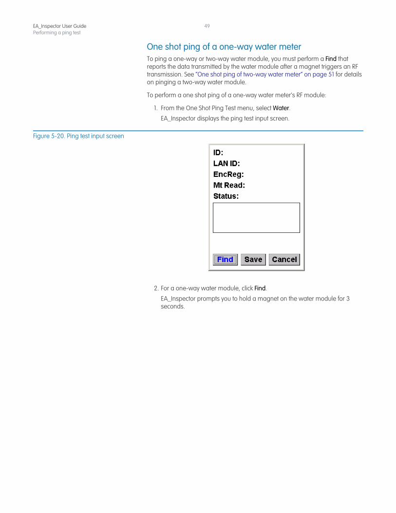
49
One shot ping of a one-way water meterTo ping a one-way or two-way water module, you must perform a Find that reports the data transmitted by the water module after a magnet triggers an RF transmission. See “One shot ping of two-way water meter” on page 51 for details on pinging a two-way water module.
To perform a one shot ping of a one-way water meter’s RF module:
1. From the One Shot Ping Test menu, select Water.
EA_Inspector displays the ping test input screen.
Figure 5-20. Ping test input screen
2. For a one-way water module, click Find.
EA_Inspector prompts you to hold a magnet on the water module for 3 seconds.
EA_Inspector User GuidePerforming a ping test
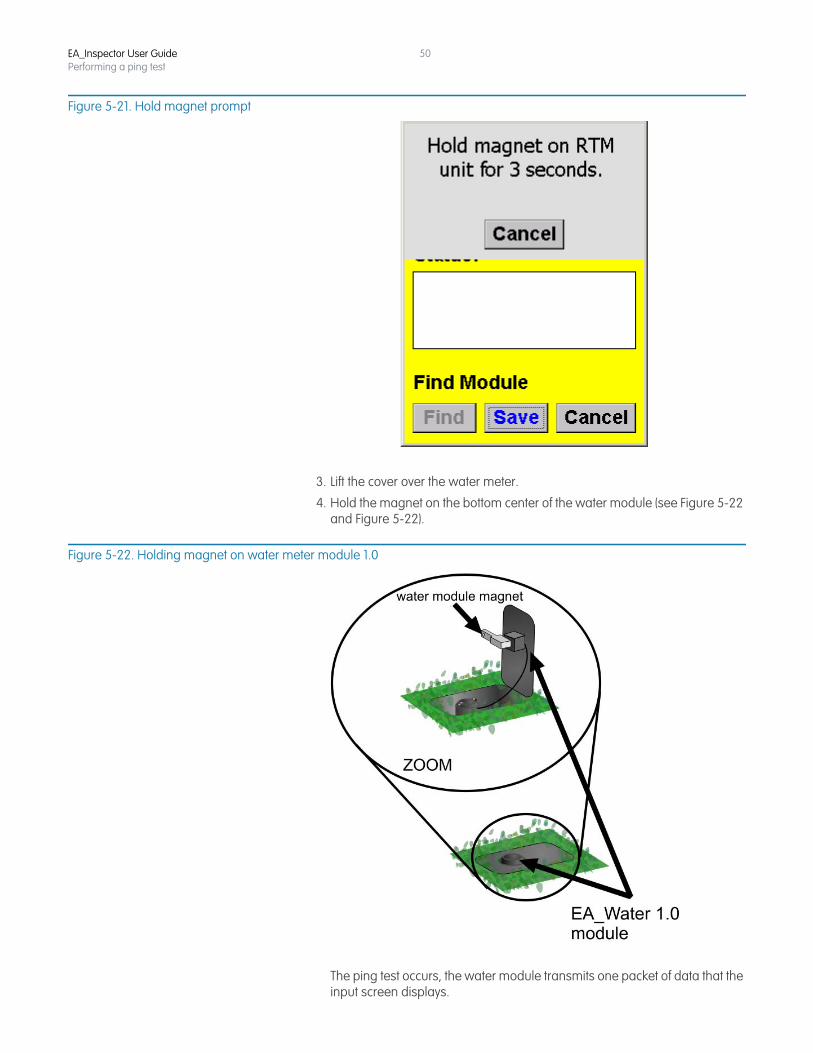
50
Figure 5-21. Hold magnet prompt
3. Lift the cover over the water meter.
4. Hold the magnet on the bottom center of the water module (see Figure 5-22 and Figure 5-22).
Figure 5-22. Holding magnet on water meter module 1.0
The ping test occurs, the water module transmits one packet of data that the input screen displays.
EA_Inspector User GuidePerforming a ping test
51
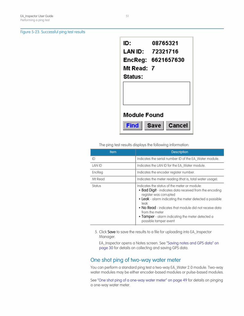
Figure 5-23. Successful ping test results
The ping test results displays the following information:
5. Click Save to save the results to a file for uploading into EA_Inspector Manager.
EA_Inspector opens a Notes screen. See “Saving notes and GPS data” on page 30 for details on collecting and saving GPS data.
One shot ping of two-way water meterYou can perform a standard ping test a two-way EA_Water 2.0 module. Two-way water modules may be either encoder-based modules or pulse-based modules.
See “One shot ping of a one-way water meter” on page 49 for details on pinging a one-way water meter.
Item Description
ID Indicates the serial number ID of the EA_Water module.
LAN ID Indicates the LAN ID for the EA_Water module.
EncReg Indicates the encoder register number.
Mt Read Indicates the meter reading (that is, total water usage).
Status Indicates the status of the meter or module:• Bad Digit - indicates data received from the encoding
register was corrupted• Leak - alarm indicating the meter detected a possible
leak• No Read - indicates that module did not receive data
from the meter• Tamper - alarm indicating the meter detected a
possible tamper event
EA_Inspector User GuidePerforming a ping test
52
To perform a one shot ping of a two-way water meter’s RF module:
1. From the One Shot Ping Test menu, select Water.
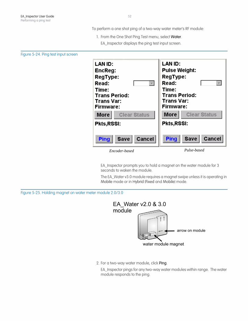
EA_Inspector displays the ping test input screen.
Figure 5-24. Ping test input screen
EA_Inspector prompts you to hold a magnet on the water module for 3 seconds to waken the module.
The EA_Water v3.0 module requires a magnet swipe unless it is operating in Mobile mode or in Hybrid (Fixed and Mobile) mode.
Figure 5-25. Holding magnet on water meter module 2.0/3.0
2. For a two-way water module, click Ping.
EA_Inspector pings for any two-way water modules within range. The water module responds to the ping.
Encoder-based Pulse-based
EA_Inspector User GuidePerforming a ping test
53
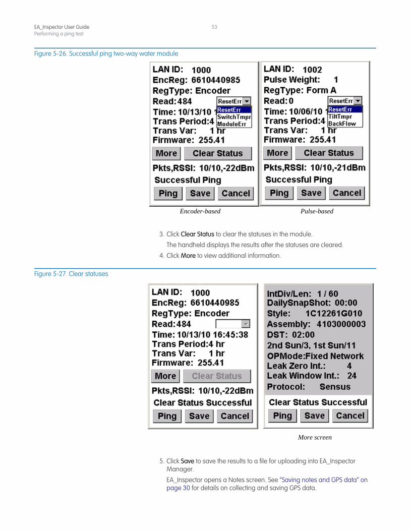
Figure 5-26. Successful ping two-way water module
3. Click Clear Status to clear the statuses in the module.
The handheld displays the results after the statuses are cleared.
4. Click More to view additional information.
Figure 5-27. Clear statuses
5. Click Save to save the results to a file for uploading into EA_Inspector Manager.
EA_Inspector opens a Notes screen. See “Saving notes and GPS data” on page 30 for details on collecting and saving GPS data.
Encoder-based Pulse-based
More screen
EA_Inspector User GuidePerforming a ping test
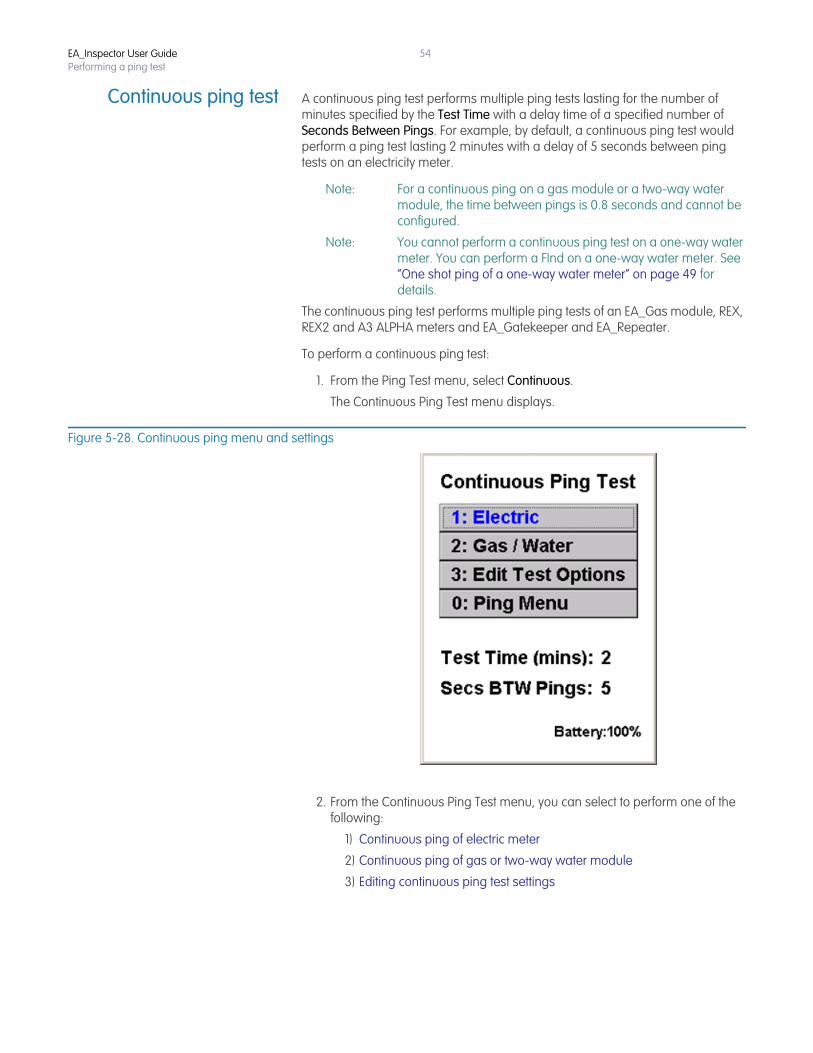
54
Continuous ping test A continuous ping test performs multiple ping tests lasting for the number of minutes specified by the Test Time with a delay time of a specified number of Seconds Between Pings. For example, by default, a continuous ping test would perform a ping test lasting 2 minutes with a delay of 5 seconds between ping tests on an electricity meter.
Note: For a continuous ping on a gas module or a two-way water module, the time between pings is 0.8 seconds and cannot be configured.
Note: You cannot perform a continuous ping test on a one-way water meter. You can perform a FInd on a one-way water meter. See “One shot ping of a one-way water meter” on page 49 for details.
The continuous ping test performs multiple ping tests of an EA_Gas module, REX, REX2 and A3 ALPHA meters and EA_Gatekeeper and EA_Repeater.
To perform a continuous ping test:
1. From the Ping Test menu, select Continuous.
The Continuous Ping Test menu displays.
Figure 5-28. Continuous ping menu and settings
2. From the Continuous Ping Test menu, you can select to perform one of the following:
1) Continuous ping of electric meter
2) Continuous ping of gas or two-way water module
3) Editing continuous ping test settings
EA_Inspector User GuidePerforming a ping test
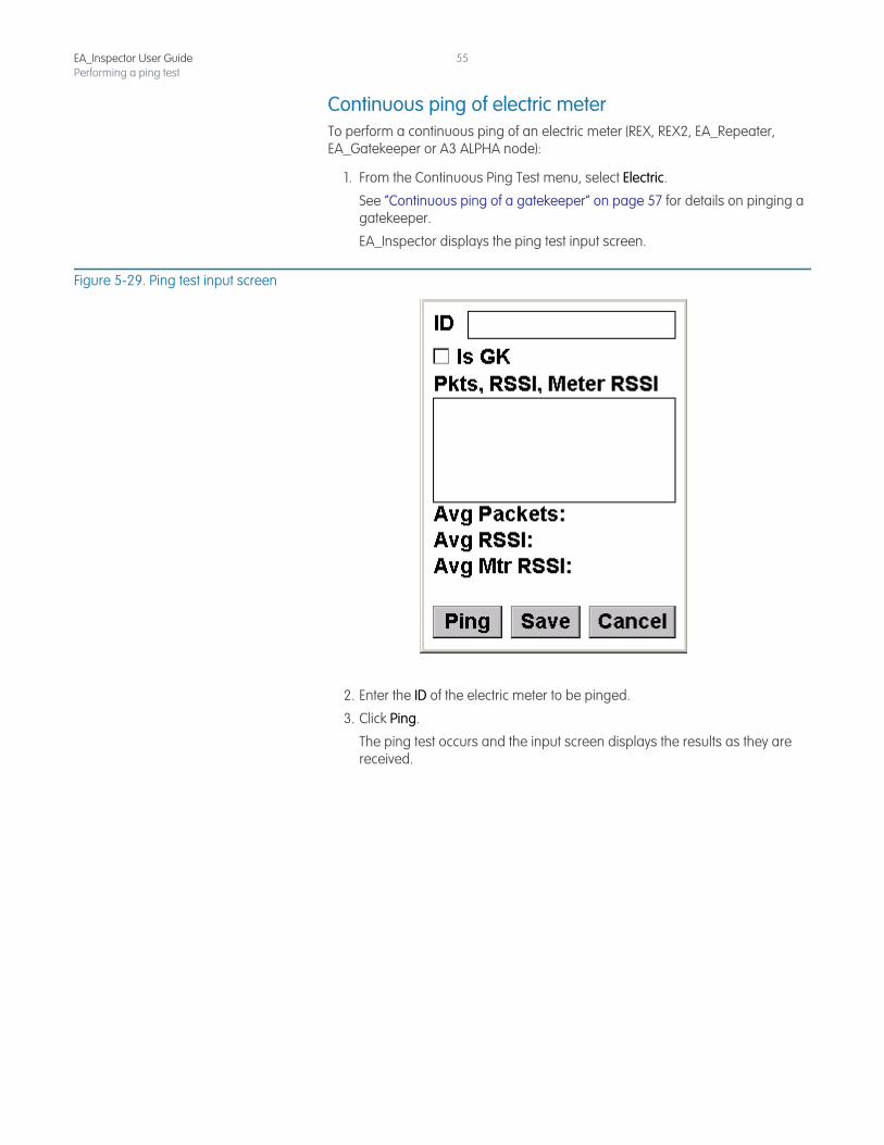
55
Continuous ping of electric meterTo perform a continuous ping of an electric meter (REX, REX2, EA_Repeater, EA_Gatekeeper or A3 ALPHA node):
1. From the Continuous Ping Test menu, select Electric.
See “Continuous ping of a gatekeeper” on page 57 for details on pinging a gatekeeper.
EA_Inspector displays the ping test input screen.
Figure 5-29. Ping test input screen
2. Enter the ID of the electric meter to be pinged.
3. Click Ping.
The ping test occurs and the input screen displays the results as they are received.
EA_Inspector User GuidePerforming a ping test
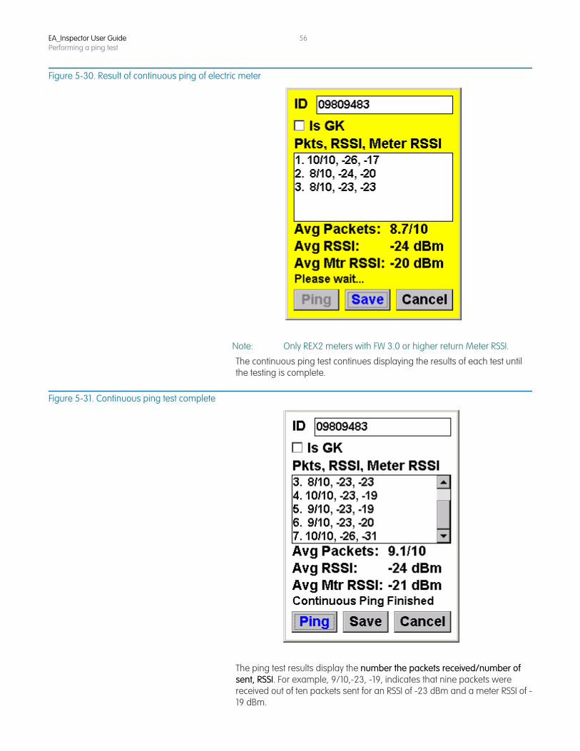
56
Figure 5-30. Result of continuous ping of electric meter
Note: Only REX2 meters with FW 3.0 or higher return Meter RSSI.
The continuous ping test continues displaying the results of each test until the testing is complete.
Figure 5-31. Continuous ping test complete
The ping test results display the number the packets received/number of sent, RSSI. For example, 9/10,-23, -19, indicates that nine packets were received out of ten packets sent for an RSSI of -23 dBm and a meter RSSI of -19 dBm.
EA_Inspector User GuidePerforming a ping test
57
4. Click Save to save the results to a file for uploading into EA_Inspector Manager.
EA_Inspector opens a Notes screen. See “Saving notes and GPS data” on page 30 for details on collecting and saving GPS data.
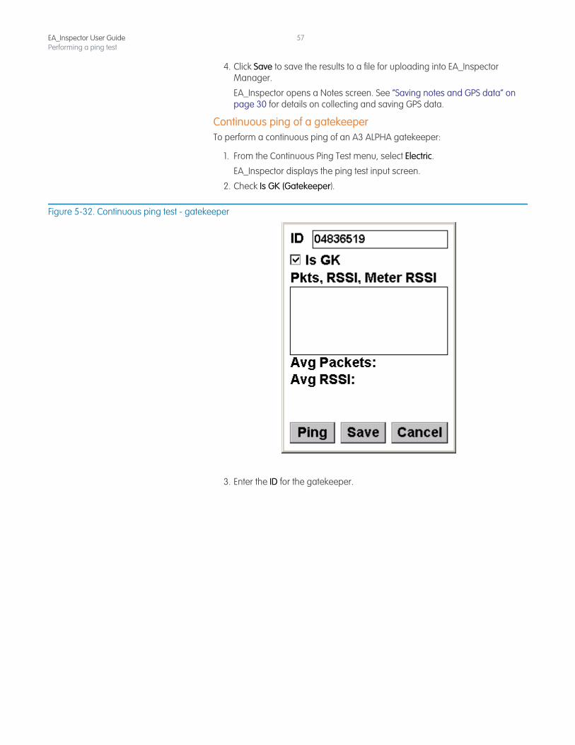
Continuous ping of a gatekeeperTo perform a continuous ping of an A3 ALPHA gatekeeper:
1. From the Continuous Ping Test menu, select Electric.
EA_Inspector displays the ping test input screen.
2. Check Is GK (Gatekeeper).
Figure 5-32. Continuous ping test - gatekeeper
3. Enter the ID for the gatekeeper.
EA_Inspector User GuidePerforming a ping test
58
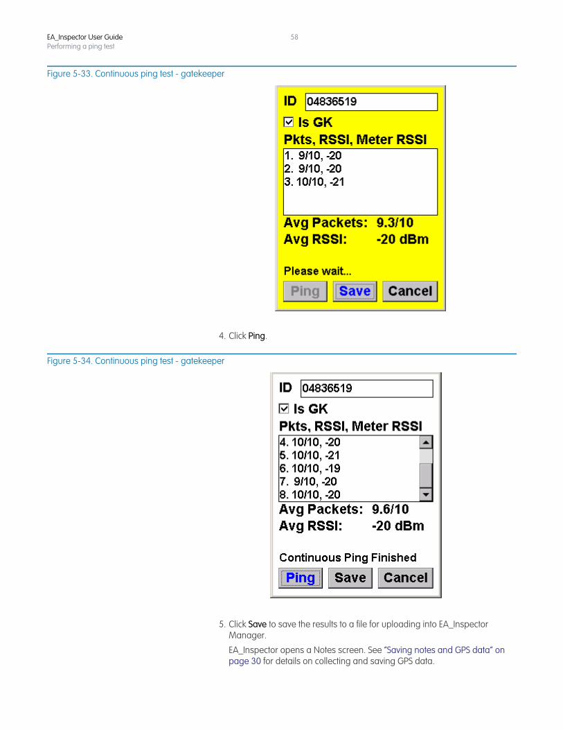
Figure 5-33. Continuous ping test - gatekeeper
4. Click Ping.
Figure 5-34. Continuous ping test - gatekeeper
5. Click Save to save the results to a file for uploading into EA_Inspector Manager.
EA_Inspector opens a Notes screen. See “Saving notes and GPS data” on page 30 for details on collecting and saving GPS data.
EA_Inspector User GuidePerforming a ping test
59
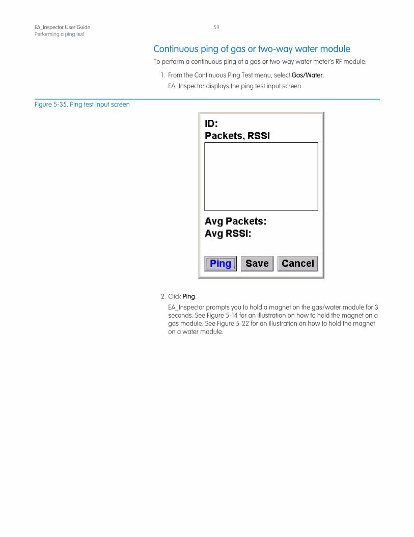
Continuous ping of gas or two-way water moduleTo perform a continuous ping of a gas or two-way water meter’s RF module:
1. From the Continuous Ping Test menu, select Gas/Water.
EA_Inspector displays the ping test input screen.
Figure 5-35. Ping test input screen
2. Click Ping.
EA_Inspector prompts you to hold a magnet on the gas/water module for 3 seconds. See Figure 5-14 for an illustration on how to hold the magnet on a gas module. See Figure 5-22 for an illustration on how to hold the magnet on a water module.
EA_Inspector User GuidePerforming a ping test
60
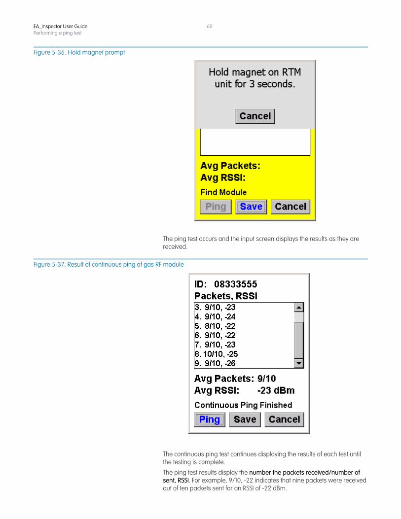
Figure 5-36. Hold magnet prompt
The ping test occurs and the input screen displays the results as they are received.
Figure 5-37. Result of continuous ping of gas RF module
The continuous ping test continues displaying the results of each test until the testing is complete.
The ping test results display the number the packets received/number of sent, RSSI. For example, 9/10, -22 indicates that nine packets were received out of ten packets sent for an RSSI of -22 dBm.
EA_Inspector User GuidePerforming a ping test
61
3. Click Save to save the results to a file for uploading into EA_Inspector Manager.
EA_Inspector opens a Notes screen. See “Saving notes and GPS data” on page 30 for details on collecting and saving GPS data.
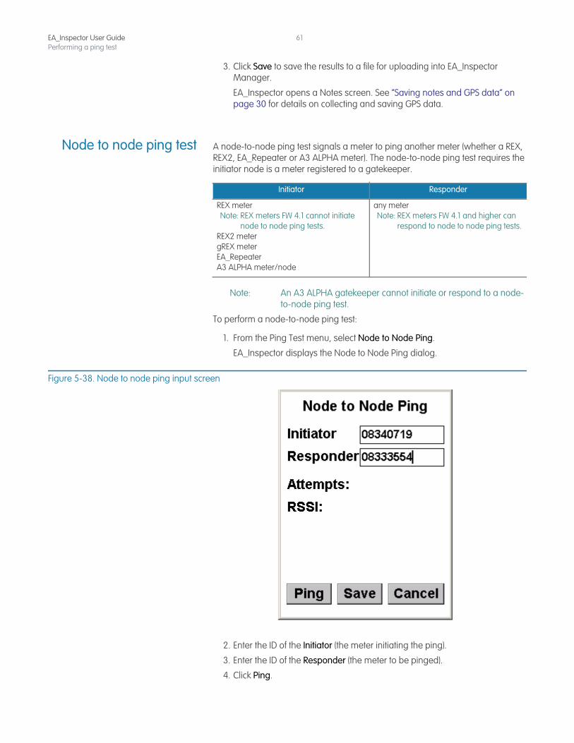
Node to node ping test A node-to-node ping test signals a meter to ping another meter (whether a REX, REX2, EA_Repeater or A3 ALPHA meter). The node-to-node ping test requires the initiator node is a meter registered to a gatekeeper.
Note: An A3 ALPHA gatekeeper cannot initiate or respond to a node-to-node ping test.
To perform a node-to-node ping test:
1. From the Ping Test menu, select Node to Node Ping.
EA_Inspector displays the Node to Node Ping dialog.
Figure 5-38. Node to node ping input screen
2. Enter the ID of the Initiator (the meter initiating the ping).
3. Enter the ID of the Responder (the meter to be pinged).
4. Click Ping.
Initiator Responder
REX meterNote: REX meters FW 4.1 cannot initiate
node to node ping tests.REX2 metergREX meterEA_Repeater A3 ALPHA meter/node
any meterNote: REX meters FW 4.1 and higher can
respond to node to node ping tests.
EA_Inspector User GuidePerforming a ping test
62
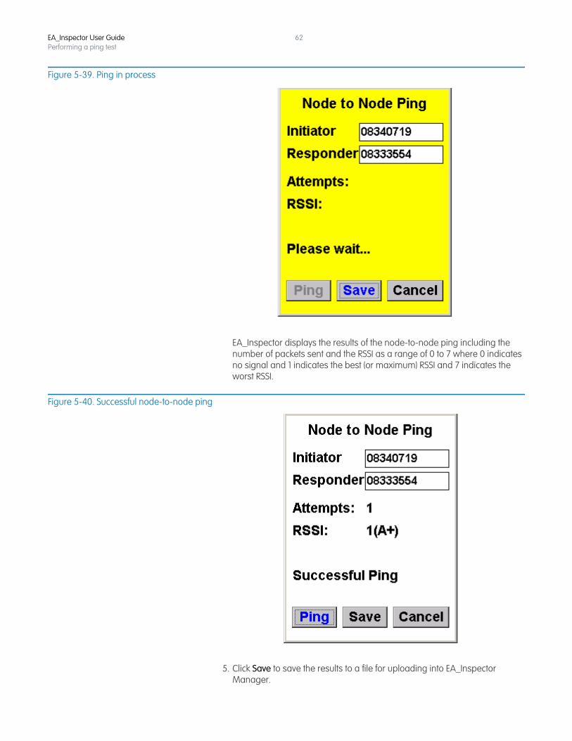
Figure 5-39. Ping in process
EA_Inspector displays the results of the node-to-node ping including the number of packets sent and the RSSI as a range of 0 to 7 where 0 indicates no signal and 1 indicates the best (or maximum) RSSI and 7 indicates the worst RSSI.
Figure 5-40. Successful node-to-node ping
5. Click Save to save the results to a file for uploading into EA_Inspector Manager.
EA_Inspector User GuidePerforming a ping test
63
EA_Inspector opens a Notes screen. See “Saving notes and GPS data” on page 30 for details on collecting and saving GPS data.
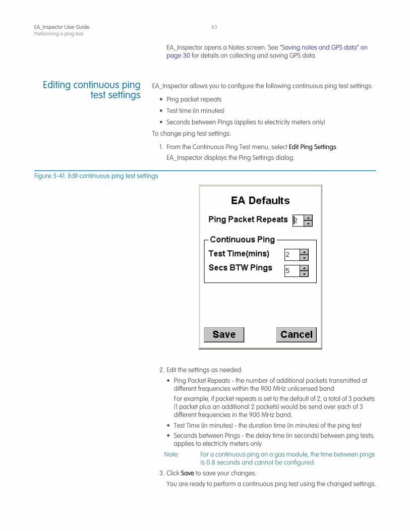
Editing continuous pingtest settings
EA_Inspector allows you to configure the following continuous ping test settings:
• Ping packet repeats
• Test time (in minutes)
• Seconds between Pings (applies to electricity meters only)
To change ping test settings:
1. From the Continuous Ping Test menu, select Edit Ping Settings.
EA_Inspector displays the Ping Settings dialog.
Figure 5-41. Edit continuous ping test settings
2. Edit the settings as needed:
• Ping Packet Repeats - the number of additional packets transmitted at different frequencies within the 900 MHz unlicensed bandFor example, if packet repeats is set to the default of 2, a total of 3 packets (1 packet plus an additional 2 packets) would be send over each of 3 different frequencies in the 900 MHz band.
• Test Time (in minutes) - the duration time (in minutes) of the ping test• Seconds between Pings - the delay time (in seconds) between ping tests;
applies to electricity meters only
Note: For a continuous ping on a gas module, the time between pings is 0.8 seconds and cannot be configured.
3. Click Save to save your changes.
You are ready to perform a continuous ping test using the changed settings.
6 LOCATING A NODE
About locating nodes EA_Inspector is capable of locating registered and unregistered REX, REX2 and A3 ALPHA node electricity meters.
Note: Elster recommends disabling EA_Inspector encryption before locating a registered or unregistered node, especially utilities supporting both unecrypted and encrypted LAN communications. See “Configuring handheld settings and utility IDs” on page 170 for details on disabling LAN encryption.
Note: Gas and water modules are battery operated devices that remain in a sleeping state until they are awakened (by magnet swipe for one-way modules or by receiving a waken signal for two-way modules). They cannot be located using the Registered Node or Unregistered Node Locator functions.
Accessing node locationmenu
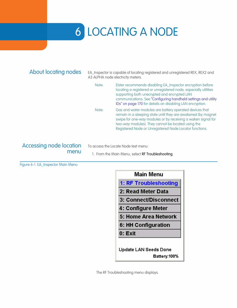
To access the Locate Node test menu:
1. From the Main Menu, select RF Troubleshooting.
Figure 6-1. EA_Inspector Main Menu
The RF Troubleshooting menu displays.
EA_Inspector User Guide
EA_Inspector User GuideLocating a node
65
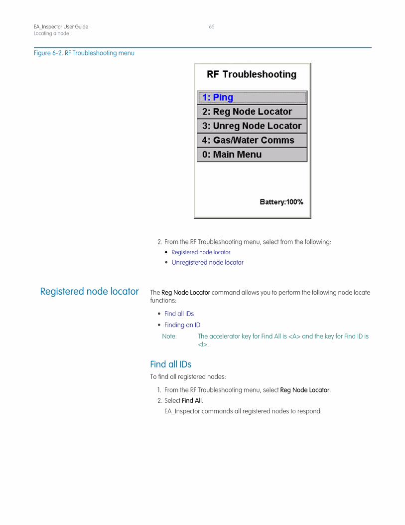
Figure 6-2. RF Troubleshooting menu
2. From the RF Troubleshooting menu, select from the following:
• Registered node locator
• Unregistered node locator
Registered node locator The Reg Node Locator command allows you to perform the following node locate functions:
• Find all IDs
• Finding an ID
Note: The accelerator key for Find All is <A> and the key for Find ID is <I>.
Find all IDsTo find all registered nodes:
1. From the RF Troubleshooting menu, select Reg Node Locator.
2. Select Find All.
EA_Inspector commands all registered nodes to respond.
EA_Inspector User GuideLocating a node
66
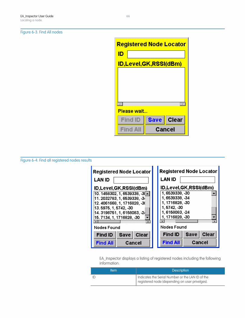
Figure 6-3. Find All nodes
Figure 6-4. Find all registered nodes results
EA_Inspector displays a listing of registered nodes including the following information:
Item Description
ID Indicates the Serial Number or the LAN ID of the registered node (depending on user privelges).
EA_Inspector User GuideLocating a node
67
3. Click Save to save the results to a file for uploading into EA_Inspector Manager.
EA_Inspector opens a Notes screen. See “Saving notes and GPS data” on page 30 for details on collecting and saving GPS data.
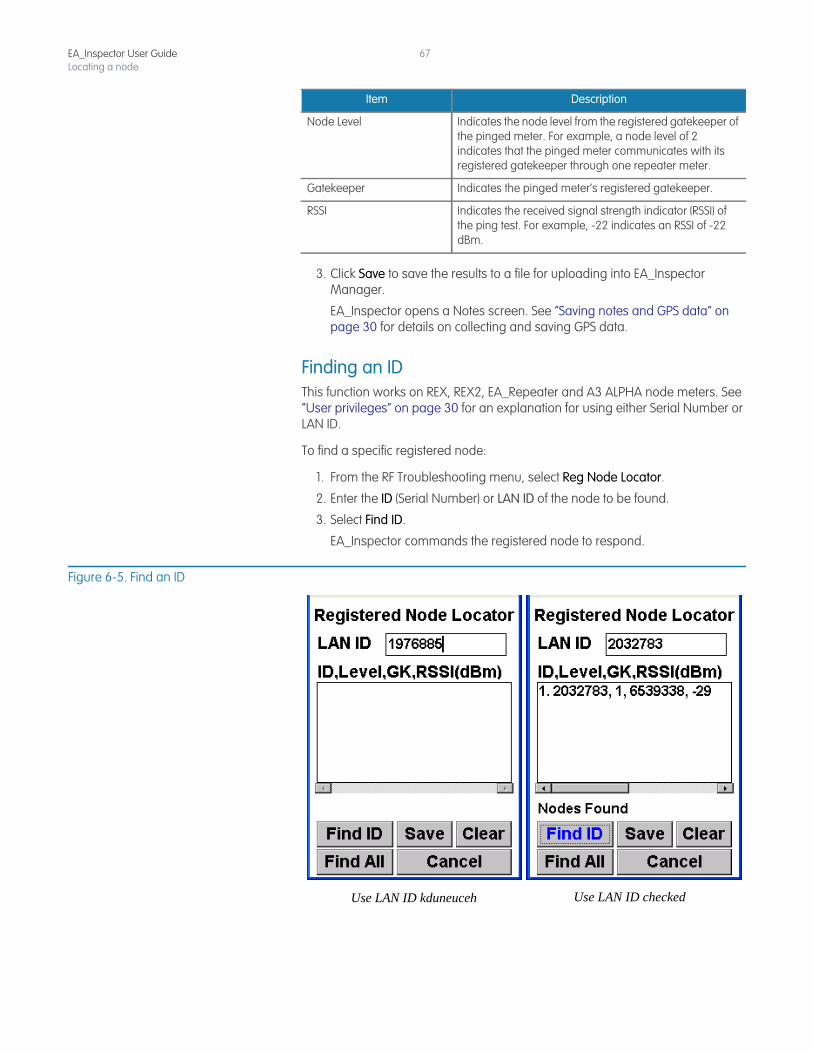
Finding an IDThis function works on REX, REX2, EA_Repeater and A3 ALPHA node meters. See “User privileges” on page 30 for an explanation for using either Serial Number or LAN ID.
To find a specific registered node:
1. From the RF Troubleshooting menu, select Reg Node Locator.
2. Enter the ID (Serial Number) or LAN ID of the node to be found.
3. Select Find ID.
EA_Inspector commands the registered node to respond.
Figure 6-5. Find an ID
Node Level Indicates the node level from the registered gatekeeper of the pinged meter. For example, a node level of 2 indicates that the pinged meter communicates with its registered gatekeeper through one repeater meter.
Gatekeeper Indicates the pinged meter’s registered gatekeeper.
RSSI Indicates the received signal strength indicator (RSSI) of the ping test. For example, -22 indicates an RSSI of -22 dBm.
Item Description
Use LAN ID kduneuceh Use LAN ID checked
EA_Inspector User GuideLocating a node
68
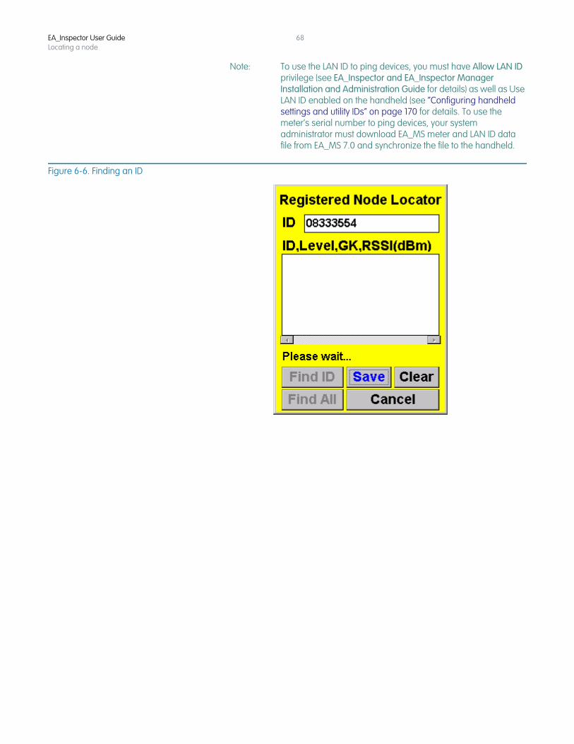
Note: To use the LAN ID to ping devices, you must have Allow LAN ID privilege (see EA_Inspector and EA_Inspector Manager Installation and Administration Guide for details) as well as Use LAN ID enabled on the handheld (see “Configuring handheld settings and utility IDs” on page 170 for details. To use the meter’s serial number to ping devices, your system administrator must download EA_MS meter and LAN ID data file from EA_MS 7.0 and synchronize the file to the handheld.
Figure 6-6. Finding an ID
EA_Inspector User GuideLocating a node
69
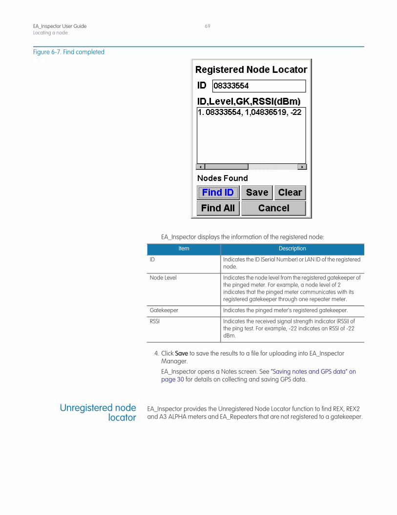
Figure 6-7. Find completed
EA_Inspector displays the information of the registered node:
4. Click Save to save the results to a file for uploading into EA_Inspector Manager.
EA_Inspector opens a Notes screen. See “Saving notes and GPS data” on page 30 for details on collecting and saving GPS data.
Unregistered nodelocator
EA_Inspector provides the Unregistered Node Locator function to find REX, REX2 and A3 ALPHA meters and EA_Repeaters that are not registered to a gatekeeper.
Item Description
ID Indicates the ID (Serial Number) or LAN ID of the registered node.
Node Level Indicates the node level from the registered gatekeeper of the pinged meter. For example, a node level of 2 indicates that the pinged meter communicates with its registered gatekeeper through one repeater meter.
Gatekeeper Indicates the pinged meter’s registered gatekeeper.
RSSI Indicates the received signal strength indicator (RSSI) of the ping test. For example, -22 indicates an RSSI of -22 dBm.
EA_Inspector User GuideLocating a node
70
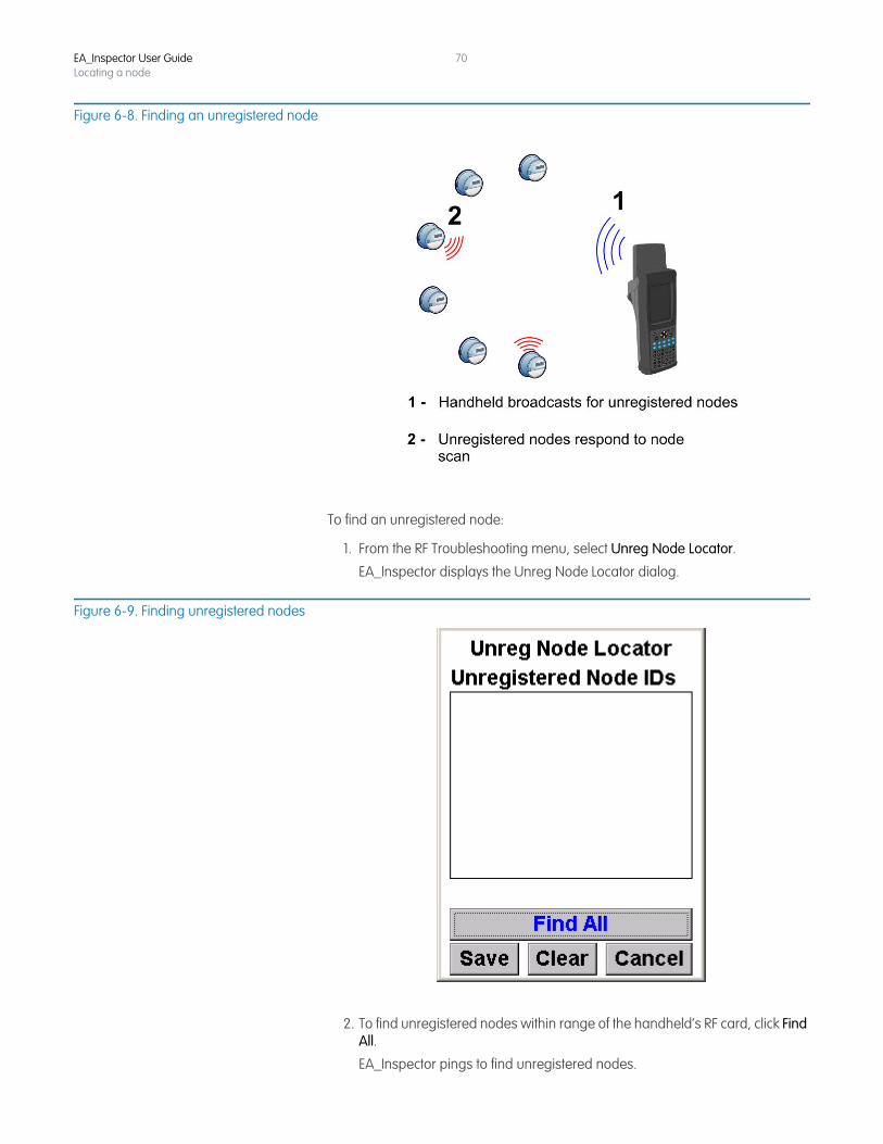
Figure 6-8. Finding an unregistered node
To find an unregistered node:
1. From the RF Troubleshooting menu, select Unreg Node Locator.
EA_Inspector displays the Unreg Node Locator dialog.
Figure 6-9. Finding unregistered nodes
2. To find unregistered nodes within range of the handheld’s RF card, click Find All.
EA_Inspector pings to find unregistered nodes.
EA_Inspector User GuideLocating a node
71
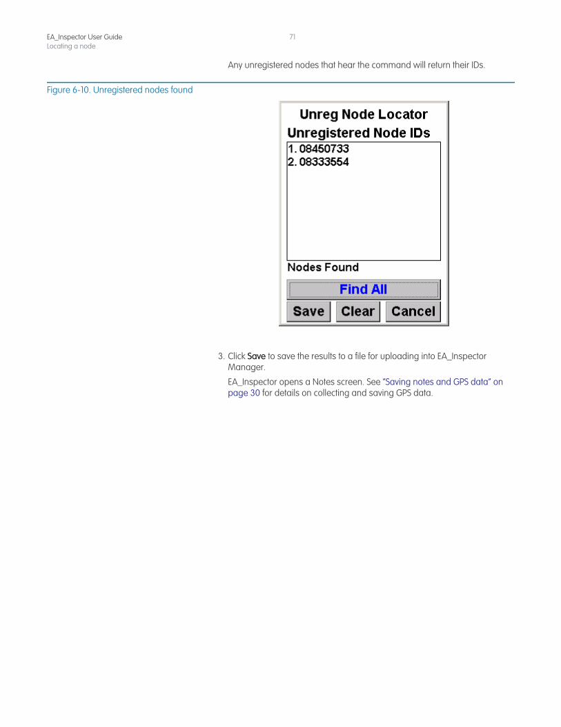
Any unregistered nodes that hear the command will return their IDs.
Figure 6-10. Unregistered nodes found
3. Click Save to save the results to a file for uploading into EA_Inspector Manager.
EA_Inspector opens a Notes screen. See “Saving notes and GPS data” on page 30 for details on collecting and saving GPS data.

EA_Inspector User GuideLocating a node
72
7 READING METER DATA
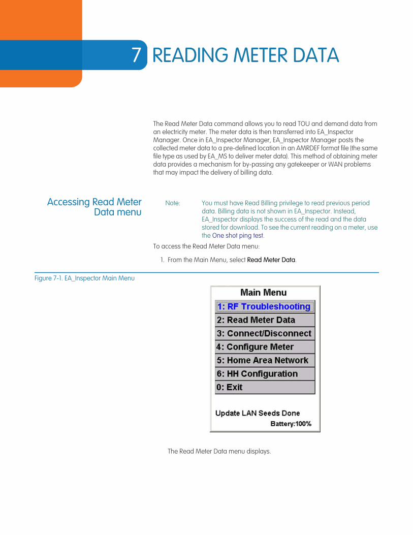
The Read Meter Data command allows you to read TOU and demand data from an electricity meter. The meter data is then transferred into EA_Inspector Manager. Once in EA_Inspector Manager, EA_Inspector Manager posts the collected meter data to a pre-defined location in an AMRDEF format file (the same file type as used by EA_MS to deliver meter data). This method of obtaining meter data provides a mechanism for by-passing any gatekeeper or WAN problems that may impact the delivery of billing data.
Accessing Read MeterData menu
Note: You must have Read Billing privilege to read previous period data. Billing data is not shown in EA_Inspector. Instead, EA_Inspector displays the success of the read and the data stored for download. To see the current reading on a meter, use the One shot ping test.
To access the Read Meter Data menu:
1. From the Main Menu, select Read Meter Data.
Figure 7-1. EA_Inspector Main Menu
The Read Meter Data menu displays.
EA_Inspector User Guide
EA_Inspector User GuideReading meter data
74
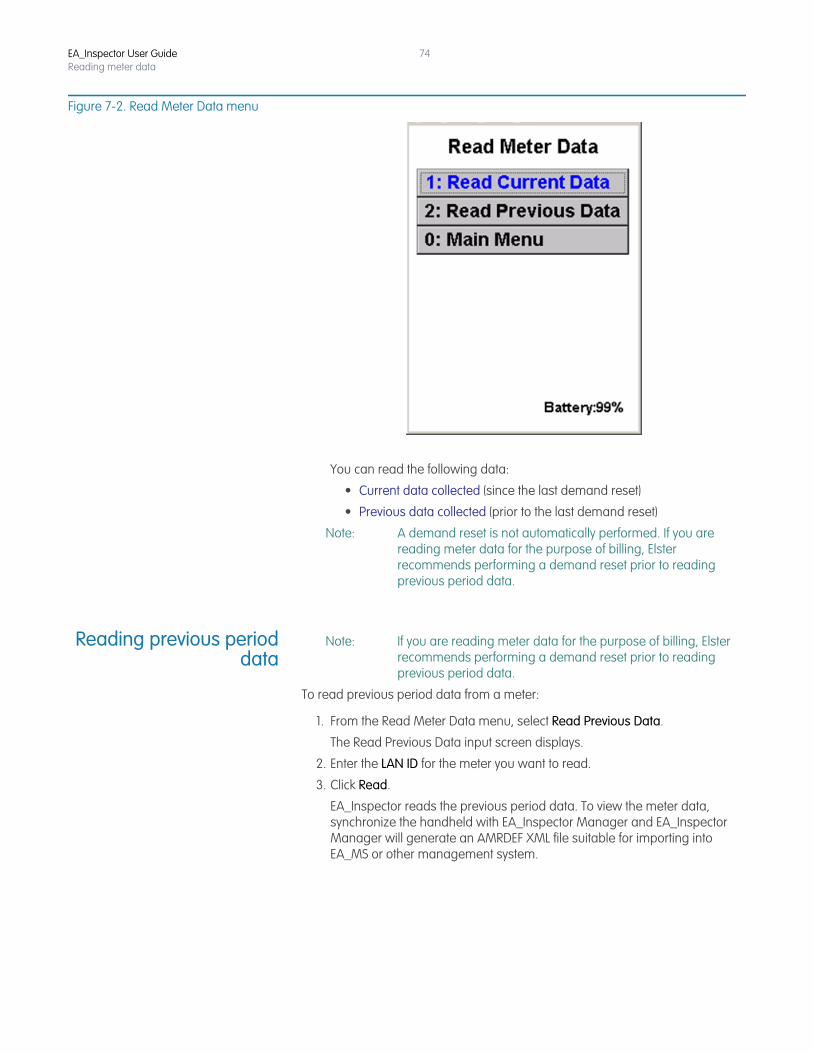
Figure 7-2. Read Meter Data menu
You can read the following data:
• Current data collected (since the last demand reset)
• Previous data collected (prior to the last demand reset)
Note: A demand reset is not automatically performed. If you are reading meter data for the purpose of billing, Elster recommends performing a demand reset prior to reading previous period data.
Reading previous perioddata
Note: If you are reading meter data for the purpose of billing, Elster recommends performing a demand reset prior to reading previous period data.
To read previous period data from a meter:
1. From the Read Meter Data menu, select Read Previous Data.
The Read Previous Data input screen displays.
2. Enter the LAN ID for the meter you want to read.
3. Click Read.
EA_Inspector reads the previous period data. To view the meter data, synchronize the handheld with EA_Inspector Manager and EA_Inspector Manager will generate an AMRDEF XML file suitable for importing into EA_MS or other management system.
EA_Inspector User GuideReading meter data
75
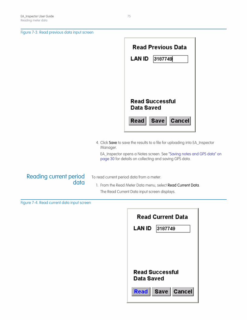
Figure 7-3. Read previous data input screen
4. Click Save to save the results to a file for uploading into EA_Inspector Manager.
EA_Inspector opens a Notes screen. See “Saving notes and GPS data” on page 30 for details on collecting and saving GPS data.
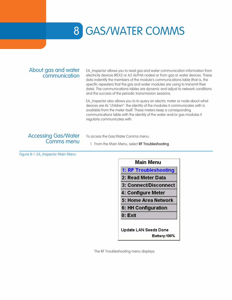
Reading current perioddata
To read current period data from a meter:
1. From the Read Meter Data menu, select Read Current Data.
The Read Current Data input screen displays.
Figure 7-4. Read current data input screen

EA_Inspector User GuideReading meter data
76
2. Enter the LAN ID for the meter you want to read.
3. Click Read.
4. Click Save to save the results to a file for uploading into EA_Inspector Manager.
EA_Inspector opens a Notes screen. See “Saving notes and GPS data” on page 30 for details on collecting and saving GPS data.
8 GAS/WATER COMMS
About gas and watercommunication
EA_Inspector allows you to read gas and water communication information from electricity devices (REX2 or A3 ALPHA nodes) or from gas or water devices. These data indentify the members of the module’s communications table (that is, the specific repeaters that the gas and water modules are using to transmit their data). The communications tables are dynamic and adjust to network conditions and the success of the periodic transmission sessions.
EA_Inspector also allows you to to query an electric meter or node about what devices are its “children”: the identity of the modules it communicates with is available from the meter itself. These meters keep a corresponding communications table with the identity of the water and/or gas modules it regularly communicates with.
Accessing Gas/WaterComms menu
To access the Gas/Water Comms menu:
1. From the Main Menu, select RF Troubleshooting.
Figure 8-1. EA_Inspector Main Menu
The RF Troubleshooting menu displays.
EA_Inspector User Guide
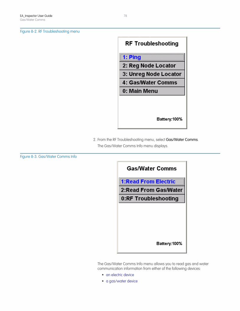
EA_Inspector User GuideGas/Water Comms
78
Figure 8-2. RF Troubleshooting menu
2. From the RF Troubleshooting menu, select Gas/Water Comms.
The Gas/Water Comms Info menu displays.
Figure 8-3. Gas/Water Comms Info
The Gas/Water Comms Info menu allows you to read gas and water communication information from either of the following devices:
• an electric device
• a gas/water device
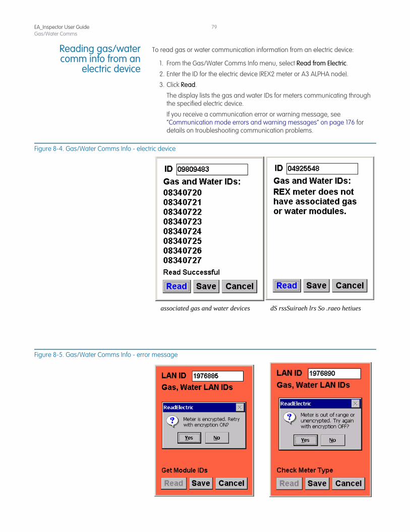
EA_Inspector User GuideGas/Water Comms
79
Reading gas/watercomm info from an
electric device
To read gas or water communication information from an electric device:
1. From the Gas/Water Comms Info menu, select Read from Electric.
2. Enter the ID for the electric device (REX2 meter or A3 ALPHA node).
3. Click Read.
The display lists the gas and water IDs for meters communicating through the specified electric device.
If you receive a communication error or warning message, see “Communication mode errors and warning messages” on page 176 for details on troubleshooting communication problems.
Figure 8-4. Gas/Water Comms Info - electric device
Figure 8-5. Gas/Water Comms Info - error message
dS rssSuiraeh lrs So .raeo hetiuesassociated gas and water devices
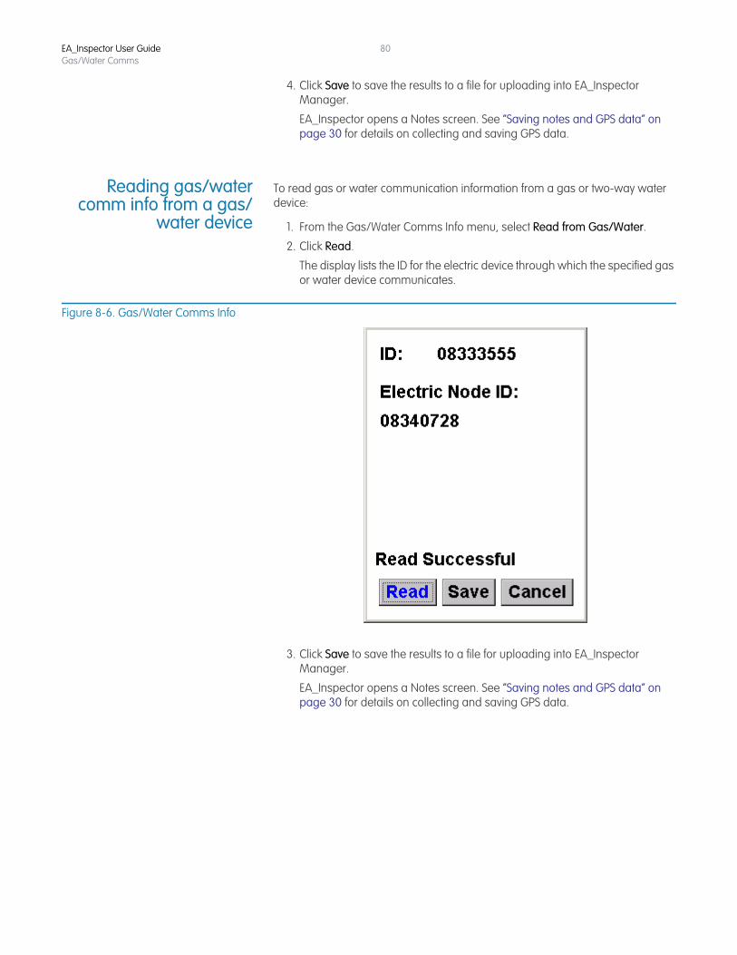
EA_Inspector User GuideGas/Water Comms
80
4. Click Save to save the results to a file for uploading into EA_Inspector Manager.
EA_Inspector opens a Notes screen. See “Saving notes and GPS data” on page 30 for details on collecting and saving GPS data.
Reading gas/watercomm info from a gas/
water device
To read gas or water communication information from a gas or two-way water device:
1. From the Gas/Water Comms Info menu, select Read from Gas/Water.
2. Click Read.
The display lists the ID for the electric device through which the specified gas or water device communicates.
Figure 8-6. Gas/Water Comms Info
3. Click Save to save the results to a file for uploading into EA_Inspector Manager.
EA_Inspector opens a Notes screen. See “Saving notes and GPS data” on page 30 for details on collecting and saving GPS data.
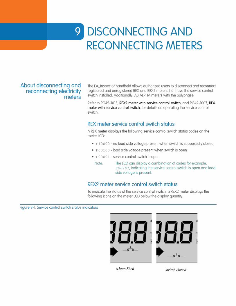
9 DISCONNECTING AND RECONNECTING METERS
About disconnecting andreconnecting electricity
meters
The EA_Inspector handheld allows authorized users to disconnect and reconnect registered and unregistered REX and REX2 meters that have the service control switch installed. Additionally, A3 ALPHA meters with the polyphase
Refer to PG42-1015, REX2 meter with service control switch, and PG42-1007, REX meter with service control switch, for details on operating the service control switch.
REX meter service control switch statusA REX meter displays the following service control switch status codes on the meter LCD:
• F10000 - no load side voltage present when switch is supposedly closed
• F00100 - load side voltage present when switch is open
• F00001 - service control switch is open
Note: The LCD can display a combination of codes for example, F00101, indicating the service control switch is open and load side voltage is present.
REX2 meter service control switch statusTo indicate the status of the service control switch, a REX2 meter displays the following icons on the meter LCD below the display quantity:
Figure 9-1. Service control switch status indicators
s.iaun Sbed switch closed
EA_Inspector User Guide
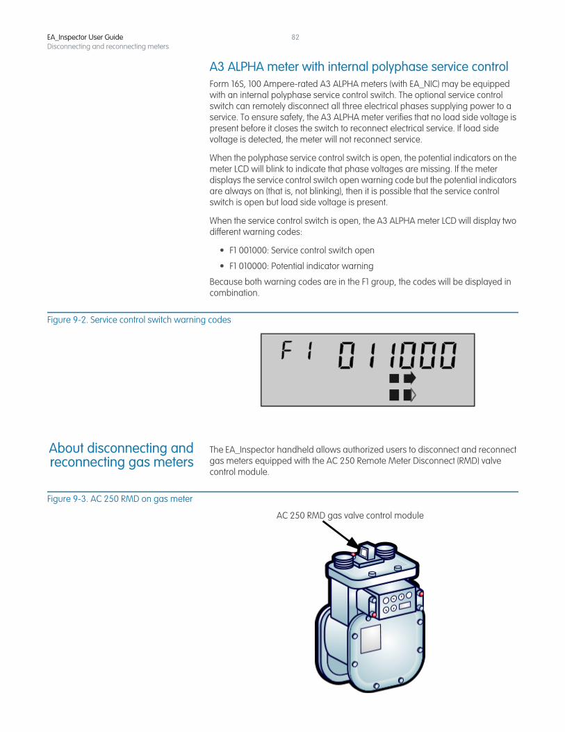
EA_Inspector User GuideDisconnecting and reconnecting meters
82
A3 ALPHA meter with internal polyphase service controlForm 16S, 100 Ampere-rated A3 ALPHA meters (with EA_NIC) may be equipped with an internal polyphase service control switch. The optional service control switch can remotely disconnect all three electrical phases supplying power to a service. To ensure safety, the A3 ALPHA meter verifies that no load side voltage is present before it closes the switch to reconnect electrical service. If load side voltage is detected, the meter will not reconnect service.
When the polyphase service control switch is open, the potential indicators on the meter LCD will blink to indicate that phase voltages are missing. If the meter displays the service control switch open warning code but the potential indicators are always on (that is, not blinking), then it is possible that the service control switch is open but load side voltage is present.
When the service control switch is open, the A3 ALPHA meter LCD will display two different warning codes:
• F1 001000: Service control switch open
• F1 010000: Potential indicator warning
Because both warning codes are in the F1 group, the codes will be displayed in combination.
Figure 9-2. Service control switch warning codes
About disconnecting andreconnecting gas meters
The EA_Inspector handheld allows authorized users to disconnect and reconnect gas meters equipped with the AC 250 Remote Meter Disconnect (RMD) valve control module.
Figure 9-3. AC 250 RMD on gas meter
AC 250 RMD gas valve control module
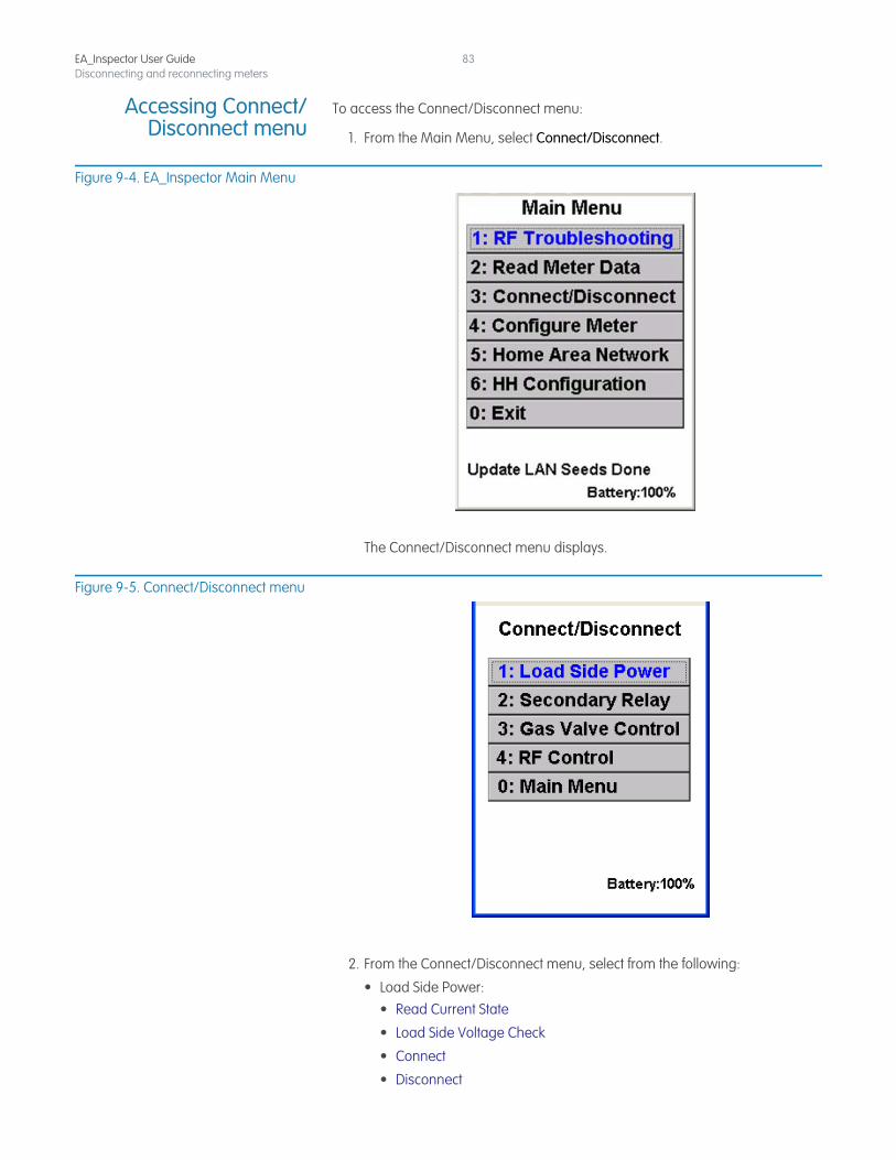
EA_Inspector User GuideDisconnecting and reconnecting meters
83
Accessing Connect/Disconnect menu
To access the Connect/Disconnect menu:
1. From the Main Menu, select Connect/Disconnect.
Figure 9-4. EA_Inspector Main Menu
The Connect/Disconnect menu displays.
Figure 9-5. Connect/Disconnect menu
2. From the Connect/Disconnect menu, select from the following:
• Load Side Power:• Read Current State
• Load Side Voltage Check
• Connect
• Disconnect
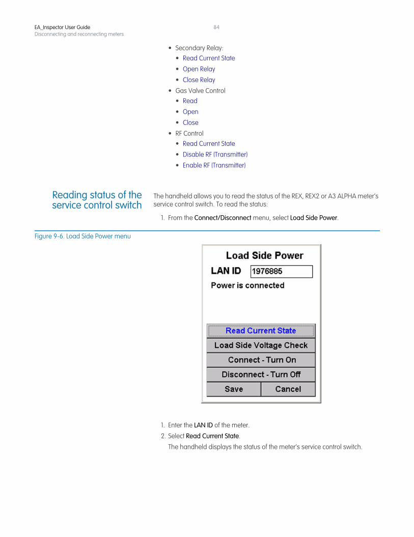
EA_Inspector User GuideDisconnecting and reconnecting meters
84
• Secondary Relay:• Read Current State
• Open Relay
• Close Relay
• Gas Valve Control • Read
• Open
• Close
• RF Control • Read Current State
• Disable RF (Transmitter)
• Enable RF (Transmitter)
Reading status of theservice control switch
The handheld allows you to read the status of the REX, REX2 or A3 ALPHA meter’s service control switch. To read the status:
1. From the Connect/Disconnect menu, select Load Side Power.
Figure 9-6. Load Side Power menu
1. Enter the LAN ID of the meter.
2. Select Read Current State.
The handheld displays the status of the meter’s service control switch.
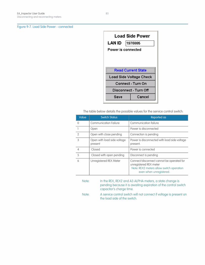
EA_Inspector User GuideDisconnecting and reconnecting meters
85
Figure 9-7. Load Side Power - connected
The table below details the possible values for the service control switch:
Note: In the REX, REX2 and A3 ALPHA meters, a state change is pending because it is awaiting expiration of the control switch capacitor’s charge time.
Note: A service control switch will not connect if voltage is present on the load side of the switch.
Value Switch Status Reported as
0 Communication Failure Communication failure
1 Open Power is disconnected
2 Open with close pending Connection is pending
3 Open with load side voltage present
Power is disconnected with load side voltage present.
4 Closed Power is connected
5 Closed with open pending Disconnect is pending
6 Unregistered REX Meter Connect/disconnect cannot be operated for unregistered REX meterNote: REX2 meters allow switch operation
even when unregistered.
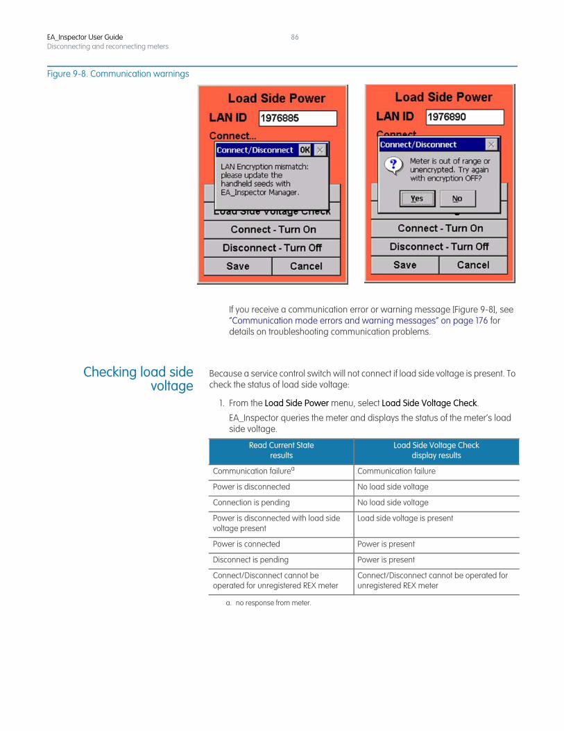
EA_Inspector User GuideDisconnecting and reconnecting meters
86
Figure 9-8. Communication warnings
If you receive a communication error or warning message [Figure 9-8], see “Communication mode errors and warning messages” on page 176 for details on troubleshooting communication problems.
Checking load sidevoltage
Because a service control switch will not connect if load side voltage is present. To check the status of load side voltage:
1. From the Load Side Power menu, select Load Side Voltage Check.
EA_Inspector queries the meter and displays the status of the meter’s load side voltage.
Read Current State results
Load Side Voltage Check display results
Communication failurea
a. no response from meter.
Communication failure
Power is disconnected No load side voltage
Connection is pending No load side voltage
Power is disconnected with load side voltage present
Load side voltage is present
Power is connected Power is present
Disconnect is pending Power is present
Connect/Disconnect cannot be operated for unregistered REX meter
Connect/Disconnect cannot be operated for unregistered REX meter
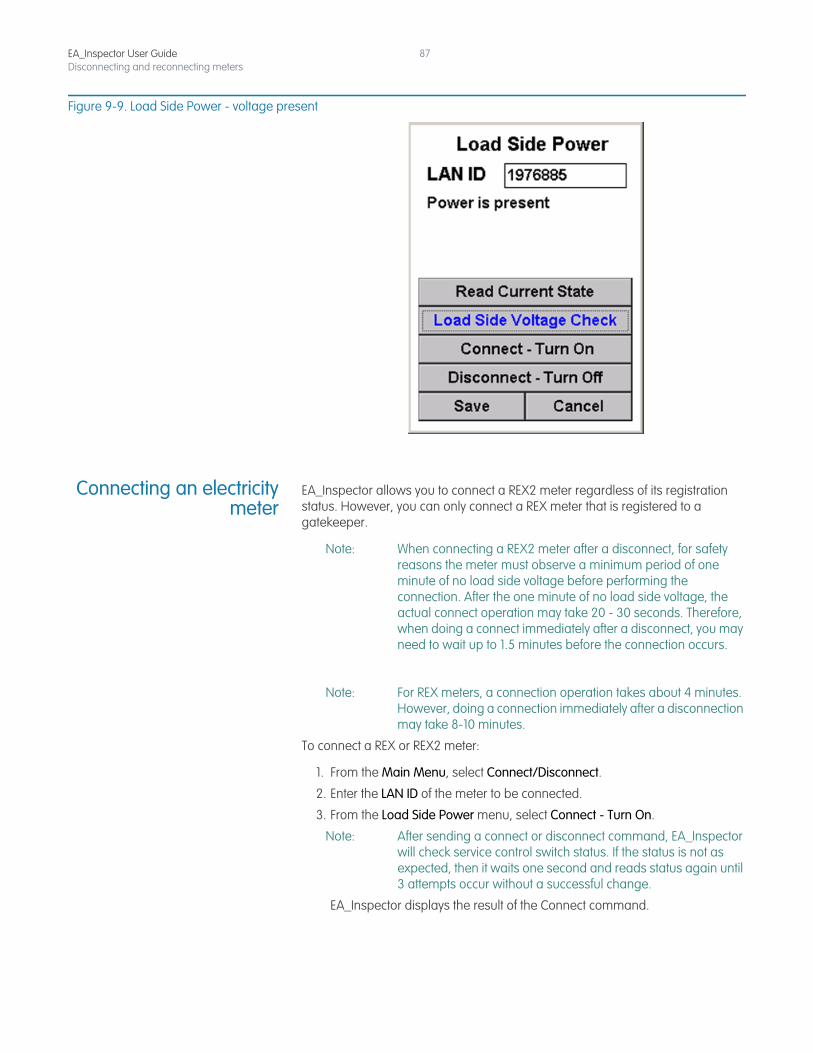
EA_Inspector User GuideDisconnecting and reconnecting meters
87
Figure 9-9. Load Side Power - voltage present
Connecting an electricitymeter
EA_Inspector allows you to connect a REX2 meter regardless of its registration status. However, you can only connect a REX meter that is registered to a gatekeeper.
Note: When connecting a REX2 meter after a disconnect, for safety reasons the meter must observe a minimum period of one minute of no load side voltage before performing the connection. After the one minute of no load side voltage, the actual connect operation may take 20 - 30 seconds. Therefore, when doing a connect immediately after a disconnect, you may need to wait up to 1.5 minutes before the connection occurs.
Note: For REX meters, a connection operation takes about 4 minutes. However, doing a connection immediately after a disconnection may take 8-10 minutes.
To connect a REX or REX2 meter:
1. From the Main Menu, select Connect/Disconnect.
2. Enter the LAN ID of the meter to be connected.
3. From the Load Side Power menu, select Connect - Turn On.
Note: After sending a connect or disconnect command, EA_Inspector will check service control switch status. If the status is not as expected, then it waits one second and reads status again until 3 attempts occur without a successful change.
EA_Inspector displays the result of the Connect command.
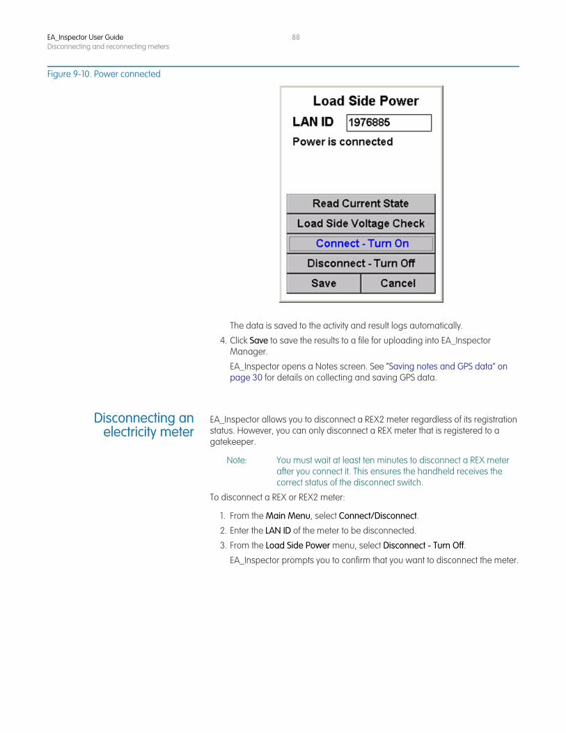
EA_Inspector User GuideDisconnecting and reconnecting meters
88
Figure 9-10. Power connected
The data is saved to the activity and result logs automatically.
4. Click Save to save the results to a file for uploading into EA_Inspector Manager.
EA_Inspector opens a Notes screen. See “Saving notes and GPS data” on page 30 for details on collecting and saving GPS data.
Disconnecting anelectricity meter
EA_Inspector allows you to disconnect a REX2 meter regardless of its registration status. However, you can only disconnect a REX meter that is registered to a gatekeeper.
Note: You must wait at least ten minutes to disconnect a REX meter after you connect it. This ensures the handheld receives the correct status of the disconnect switch.
To disconnect a REX or REX2 meter:
1. From the Main Menu, select Connect/Disconnect.
2. Enter the LAN ID of the meter to be disconnected.
3. From the Load Side Power menu, select Disconnect - Turn Off.
EA_Inspector prompts you to confirm that you want to disconnect the meter.
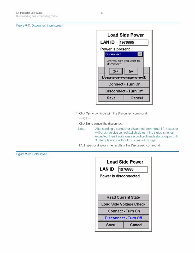
EA_Inspector User GuideDisconnecting and reconnecting meters
89
Figure 9-11. Disconnect input screen
4. Click Yes to continue with the Disconnect command.
— OR —
Click No to cancel the disconnect.
Note: After sending a connect or disconnect command, EA_Inspector will check service control switch status. If the status is not as expected, then it waits one second and reads status again until 3 attempts occur without a successful change.
EA_Inspector displays the results of the Disconnect command.
Figure 9-12. Data saved
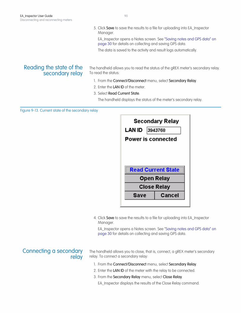
EA_Inspector User GuideDisconnecting and reconnecting meters
90
5. Click Save to save the results to a file for uploading into EA_Inspector Manager.
EA_Inspector opens a Notes screen. See “Saving notes and GPS data” on page 30 for details on collecting and saving GPS data.
The data is saved to the activity and result logs automatically.
Reading the state of thesecondary relay
The handheld allows you to read the status of the gREX meter’s secondary relay. To read the status:
1. From the Connect/Disconnect menu, select Secondary Relay.
2. Enter the LAN ID of the meter.
3. Select Read Current State.
The handheld displays the status of the meter’s secondary relay.
Figure 9-13. Current state of the secondary relay
4. Click Save to save the results to a file for uploading into EA_Inspector Manager.
EA_Inspector opens a Notes screen. See “Saving notes and GPS data” on page 30 for details on collecting and saving GPS data.
Connecting a secondaryrelay
The handheld allows you to close, that is, connect, a gREX meter’s secondary relay. To connect a secondary relay:
1. From the Connect/Disconnect menu, select Secondary Relay.
2. Enter the LAN ID of the meter with the relay to be connected.
3. From the Secondary Relay menu, select Close Relay.
EA_Inspector displays the results of the Close Relay command.
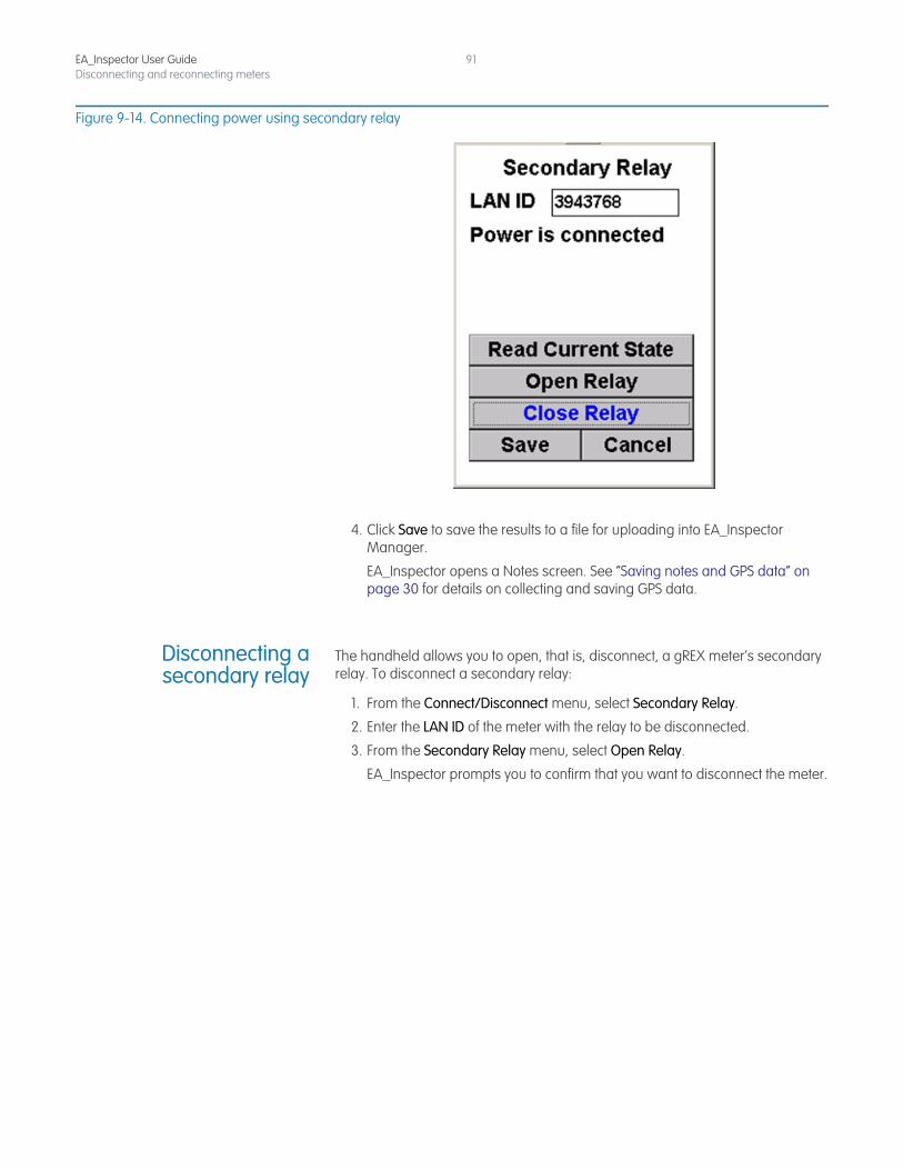
EA_Inspector User GuideDisconnecting and reconnecting meters
91
Figure 9-14. Connecting power using secondary relay
4. Click Save to save the results to a file for uploading into EA_Inspector Manager.
EA_Inspector opens a Notes screen. See “Saving notes and GPS data” on page 30 for details on collecting and saving GPS data.
Disconnecting asecondary relay
The handheld allows you to open, that is, disconnect, a gREX meter’s secondary relay. To disconnect a secondary relay:
1. From the Connect/Disconnect menu, select Secondary Relay.
2. Enter the LAN ID of the meter with the relay to be disconnected.
3. From the Secondary Relay menu, select Open Relay.
EA_Inspector prompts you to confirm that you want to disconnect the meter.
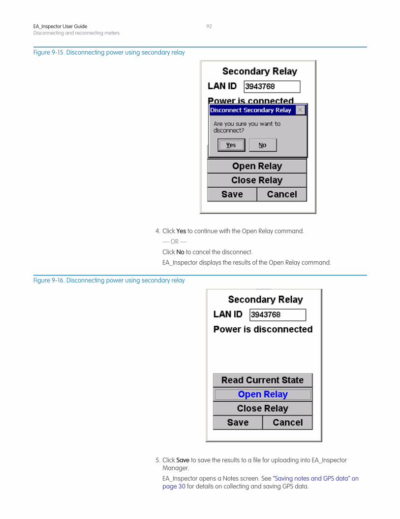
EA_Inspector User GuideDisconnecting and reconnecting meters
92
Figure 9-15. Disconnecting power using secondary relay
4. Click Yes to continue with the Open Relay command.
— OR —
Click No to cancel the disconnect.
EA_Inspector displays the results of the Open Relay command.
Figure 9-16. Disconnecting power using secondary relay
5. Click Save to save the results to a file for uploading into EA_Inspector Manager.
EA_Inspector opens a Notes screen. See “Saving notes and GPS data” on page 30 for details on collecting and saving GPS data.
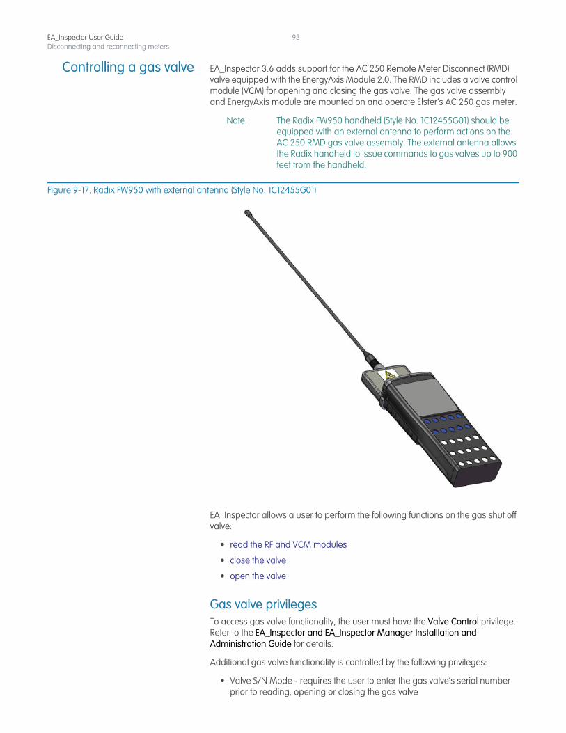
EA_Inspector User GuideDisconnecting and reconnecting meters
93
Controlling a gas valve EA_Inspector 3.6 adds support for the AC 250 Remote Meter Disconnect (RMD) valve equipped with the EnergyAxis Module 2.0. The RMD includes a valve control module (VCM) for opening and closing the gas valve. The gas valve assembly and EnergyAxis module are mounted on and operate Elster’s AC 250 gas meter.
Note: The Radix FW950 handheld (Style No. 1C12455G01) should be equipped with an external antenna to perform actions on the AC 250 RMD gas valve assembly. The external antenna allows the Radix handheld to issue commands to gas valves up to 900 feet from the handheld.
Figure 9-17. Radix FW950 with external antenna (Style No. 1C12455G01)
EA_Inspector allows a user to perform the following functions on the gas shut off valve:
• read the RF and VCM modules
• close the valve
• open the valve
Gas valve privilegesTo access gas valve functionality, the user must have the Valve Control privilege. Refer to the EA_Inspector and EA_Inspector Manager Installlation and Administration Guide for details.
Additional gas valve functionality is controlled by the following privileges:
• Valve S/N Mode - requires the user to enter the gas valve’s serial number prior to reading, opening or closing the gas valve
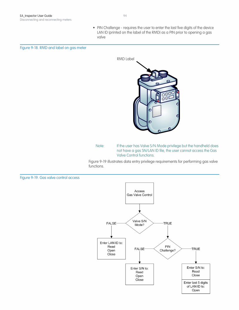
EA_Inspector User GuideDisconnecting and reconnecting meters
94
• PIN Challenge - requires the user to enter the last five digits of the device LAN ID (printed on the label of the RMD) as a PIN prior to opening a gas valve
Figure 9-18. RMD and label on gas meter
Note: If the user has Valve S/N Mode privilege but the handheld does not have a gas SN/LAN ID file, the user cannot access the Gas Valve Control functions.
Figure 9-19 illustrates data entry privilege requirements for performing gas valve functions.
Figure 9-19. Gas valve control access
RMD Label
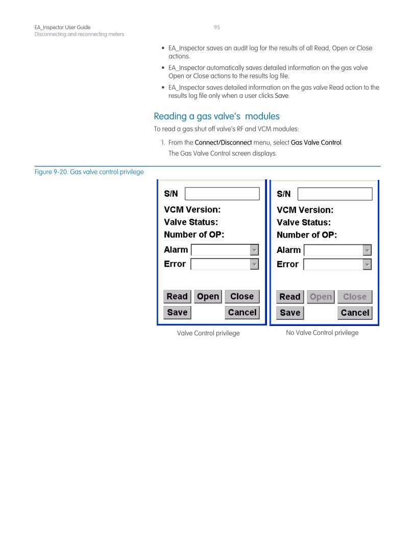
EA_Inspector User GuideDisconnecting and reconnecting meters
95
• EA_Inspector saves an audit log for the results of all Read, Open or Close actions.
• EA_Inspector automatically saves detailed information on the gas valve Open or Close actions to the results log file.
• EA_Inspector saves detailed information on the gas valve Read action to the results log file only when a user clicks Save.
Reading a gas valve’s modulesTo read a gas shut off valve’s RF and VCM modules:
1. From the Connect/Disconnect menu, select Gas Valve Control.
The Gas Valve Control screen displays.
Figure 9-20. Gas valve control privilege
No Valve Control privilegeValve Control privilege
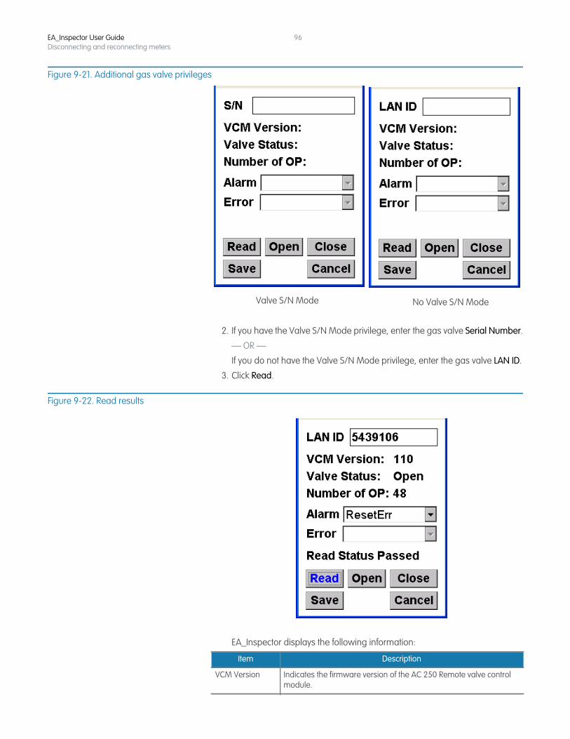
EA_Inspector User GuideDisconnecting and reconnecting meters
96
Figure 9-21. Additional gas valve privileges
2. If you have the Valve S/N Mode privilege, enter the gas valve Serial Number.
— OR —
If you do not have the Valve S/N Mode privilege, enter the gas valve LAN ID.
3. Click Read.
Figure 9-22. Read results
EA_Inspector displays the following information:
No Valve S/N ModeValve S/N Mode
Item Description
VCM Version Indicates the firmware version of the AC 250 Remote valve control module.
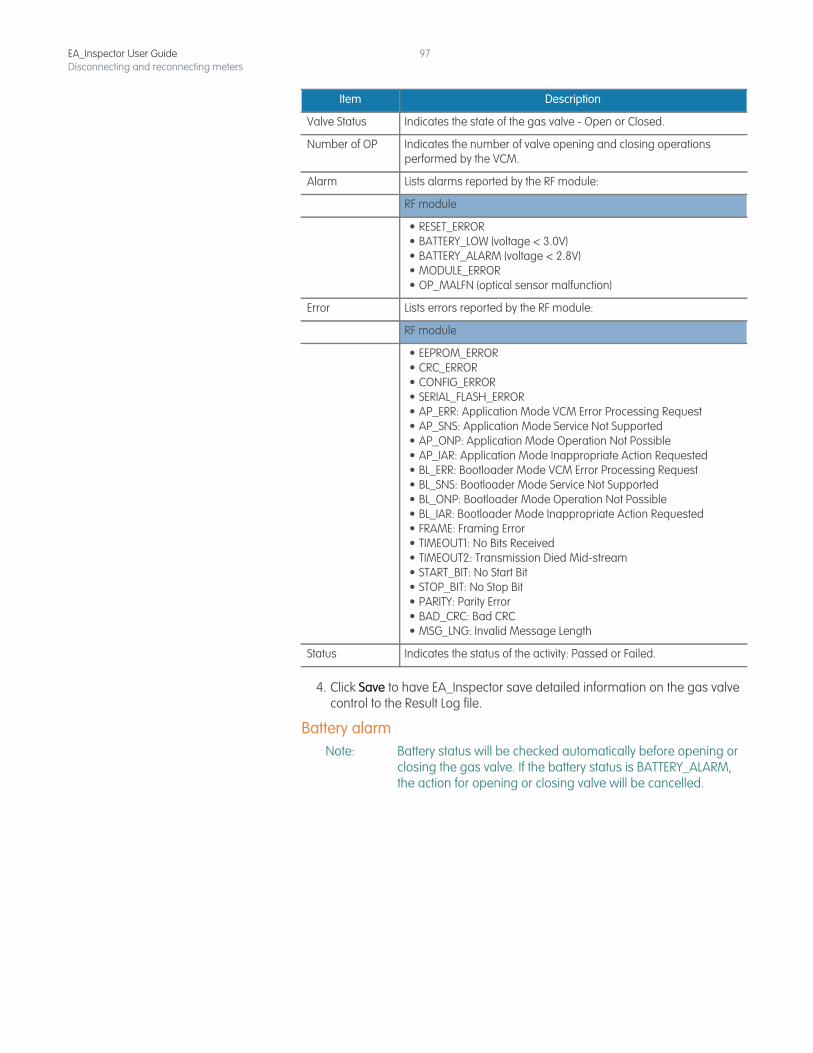
EA_Inspector User GuideDisconnecting and reconnecting meters
97
4. Click Save to have EA_Inspector save detailed information on the gas valve control to the Result Log file.
Battery alarmNote: Battery status will be checked automatically before opening or
closing the gas valve. If the battery status is BATTERY_ALARM, the action for opening or closing valve will be cancelled.
Valve Status Indicates the state of the gas valve - Open or Closed.
Number of OP Indicates the number of valve opening and closing operations performed by the VCM.
Alarm Lists alarms reported by the RF module:
RF module
• RESET_ERROR• BATTERY_LOW (voltage < 3.0V)• BATTERY_ALARM (voltage < 2.8V)• MODULE_ERROR• OP_MALFN (optical sensor malfunction)
Error Lists errors reported by the RF module:
RF module
• EEPROM_ERROR• CRC_ERROR • CONFIG_ERROR • SERIAL_FLASH_ERROR • AP_ERR: Application Mode VCM Error Processing Request• AP_SNS: Application Mode Service Not Supported• AP_ONP: Application Mode Operation Not Possible• AP_IAR: Application Mode Inappropriate Action Requested• BL_ERR: Bootloader Mode VCM Error Processing Request• BL_SNS: Bootloader Mode Service Not Supported• BL_ONP: Bootloader Mode Operation Not Possible• BL_IAR: Bootloader Mode Inappropriate Action Requested• FRAME: Framing Error• TIMEOUT1: No Bits Received• TIMEOUT2: Transmission Died Mid-stream• START_BIT: No Start Bit• STOP_BIT: No Stop Bit• PARITY: Parity Error• BAD_CRC: Bad CRC• MSG_LNG: Invalid Message Length
Status Indicates the status of the activity: Passed or Failed.
Item Description
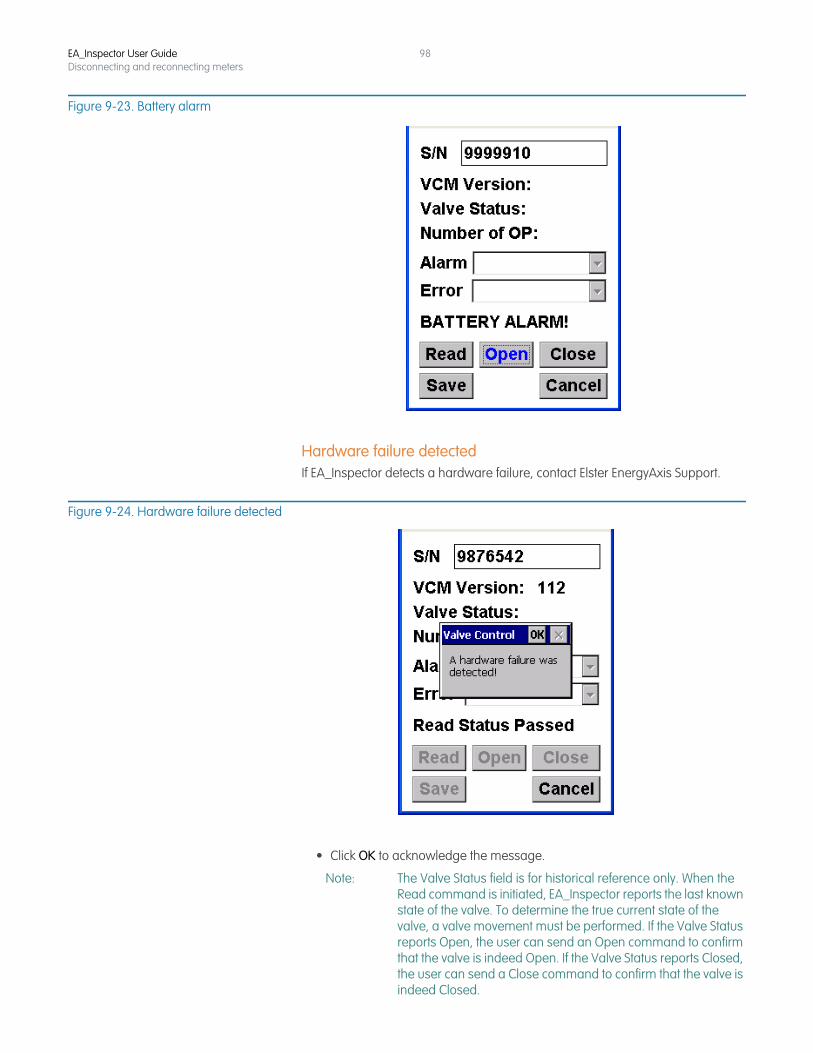
EA_Inspector User GuideDisconnecting and reconnecting meters
98
Figure 9-23. Battery alarm
Hardware failure detectedIf EA_Inspector detects a hardware failure, contact Elster EnergyAxis Support.
Figure 9-24. Hardware failure detected
• Click OK to acknowledge the message.
Note: The Valve Status field is for historical reference only. When the Read command is initiated, EA_Inspector reports the last known state of the valve. To determine the true current state of the valve, a valve movement must be performed. If the Valve Status reports Open, the user can send an Open command to confirm that the valve is indeed Open. If the Valve Status reports Closed, the user can send a Close command to confirm that the valve is indeed Closed.
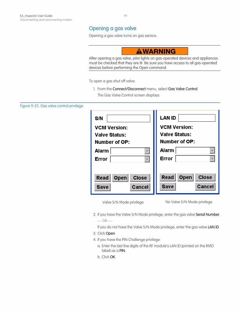
EA_Inspector User GuideDisconnecting and reconnecting meters
99
Opening a gas valveOpening a gas valve turns on gas service.
After opening a gas valve, pilot lights on gas-operated devices and appliances must be checked that they are lit. Be sure you have access to all gas-operated devices before performing the Open command.
To open a gas shut off valve:
1. From the Connect/Disconnect menu, select Gas Valve Control.
The Gas Valve Control screen displays.
Figure 9-25. Gas valve control privilege
2. If you have the Valve S/N Mode privilege, enter the gas valve Serial Number.
— OR —
If you do not have the Valve S/N Mode privilege, enter the gas valve LAN ID.
3. Click Open.
4. If you have the PIN Challenge privilege:
a. Enter the last five digits of the RF module’s LAN ID (printed on the RMD label) as a PIN.
b. Click OK.
No Valve S/N Mode privilegeValve S/N Mode privilege
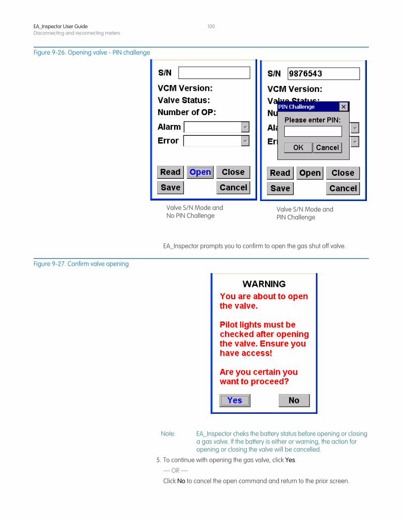
EA_Inspector User GuideDisconnecting and reconnecting meters
100
Figure 9-26. Opening valve - PIN challenge
EA_Inspector prompts you to confirm to open the gas shut off valve.
Figure 9-27. Confirm valve opening
Note: EA_Inspector cheks the battery status before opening or closing a gas valve. If the battery is either or warning, the action for opening or closing the valve will be cancelled.
5. To continue with opening the gas valve, click Yes.
— OR —
Click No to cancel the open command and return to the prior screen.
Valve S/N Mode andPIN Challenge
Valve S/N Mode andNo PIN Challenge
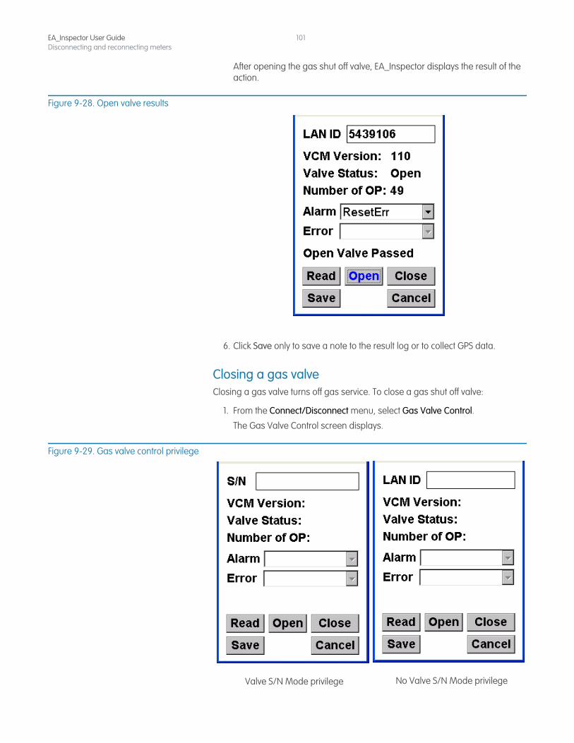
EA_Inspector User GuideDisconnecting and reconnecting meters
101
After opening the gas shut off valve, EA_Inspector displays the result of the action.
Figure 9-28. Open valve results
6. Click Save only to save a note to the result log or to collect GPS data.
Closing a gas valveClosing a gas valve turns off gas service. To close a gas shut off valve:
1. From the Connect/Disconnect menu, select Gas Valve Control.
The Gas Valve Control screen displays.
Figure 9-29. Gas valve control privilege
No Valve S/N Mode privilegeValve S/N Mode privilege
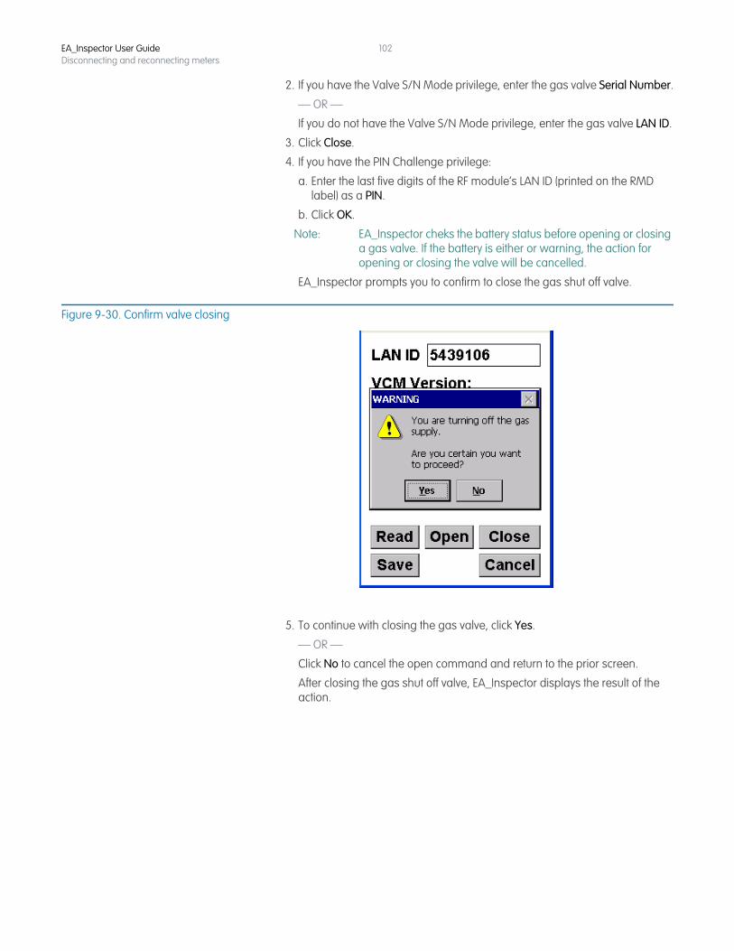
EA_Inspector User GuideDisconnecting and reconnecting meters
102
2. If you have the Valve S/N Mode privilege, enter the gas valve Serial Number.
— OR —
If you do not have the Valve S/N Mode privilege, enter the gas valve LAN ID.
3. Click Close.
4. If you have the PIN Challenge privilege:
a. Enter the last five digits of the RF module’s LAN ID (printed on the RMD label) as a PIN.
b. Click OK.
Note: EA_Inspector cheks the battery status before opening or closing a gas valve. If the battery is either or warning, the action for opening or closing the valve will be cancelled.
EA_Inspector prompts you to confirm to close the gas shut off valve.
Figure 9-30. Confirm valve closing
5. To continue with closing the gas valve, click Yes.
— OR —
Click No to cancel the open command and return to the prior screen.
After closing the gas shut off valve, EA_Inspector displays the result of the action.
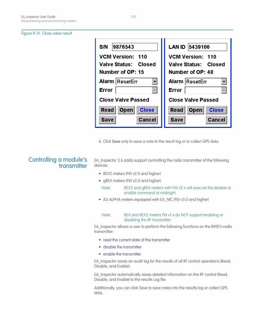
EA_Inspector User GuideDisconnecting and reconnecting meters
103
Figure 9-31. Close valve result
6. Click Save only to save a note to the result log or to collect GPS data.
Controlling a module’stransmitter
EA_Inspector 3.6 adds support controlling the radio transmitter of the following devices:
• REX2 meters (FW v2.0 and higher)
• gREX meters (FW v2.0 and higher)
Note: REX2 and gREX meters with FW v2.x will execute the disable or enable command at midnight.
• A3 ALPHA meters equipped with EA_NIC (FW v3.0 and higher)
Note: REX and REX2 meters FW v1.x do NOT support enabling or disabling the RF transmitter.
EA_Inspector allows a user to perform the following functions on the RMD’s radio transmitter:
• read the current state of the transmitter
• disable the transmitter
• enable the transmitter
EA_Inspector saves an audit log for the results of all RF control operations (Read, Disable, and Enable).
EA_Inspector automatically saves detailed information on the RF control (Read, Disable, and Enable) to the results Log file.
Additionally, you can click Save to save notes into the results log or collect GPS data.
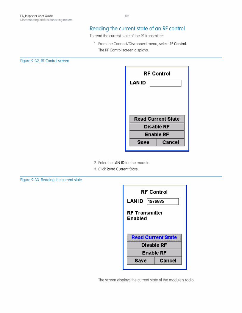
EA_Inspector User GuideDisconnecting and reconnecting meters
104
Reading the current state of an RF controlTo read the current state of the RF transmitter:
1. From the Connect/Disconnect menu, select RF Control.
The RF Control screen displays.
Figure 9-32. RF Control screen
2. Enter the LAN ID for the module.
3. Click Read Current State.
Figure 9-33. Reading the current state
The screen displays the current state of the module’s radio.
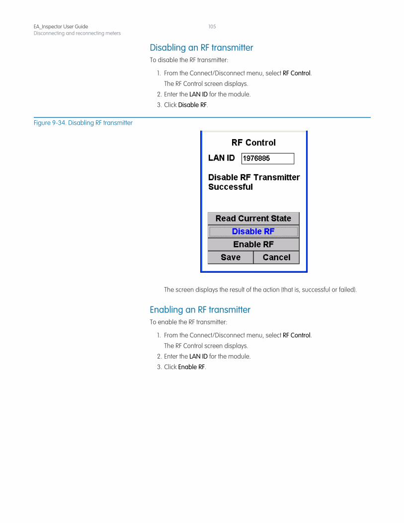
EA_Inspector User GuideDisconnecting and reconnecting meters
105
Disabling an RF transmitterTo disable the RF transmitter:
1. From the Connect/Disconnect menu, select RF Control.
The RF Control screen displays.
2. Enter the LAN ID for the module.
3. Click Disable RF.
Figure 9-34. Disabling RF transmitter
The screen displays the result of the action (that is, successful or failed).
Enabling an RF transmitterTo enable the RF transmitter:
1. From the Connect/Disconnect menu, select RF Control.
The RF Control screen displays.
2. Enter the LAN ID for the module.
3. Click Enable RF.
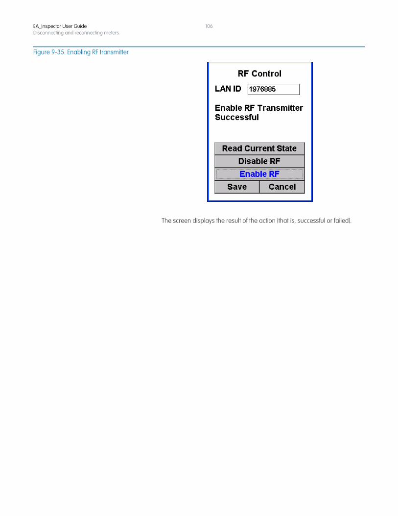
EA_Inspector User GuideDisconnecting and reconnecting meters
106
Figure 9-35. Enabling RF transmitter
The screen displays the result of the action (that is, successful or failed).
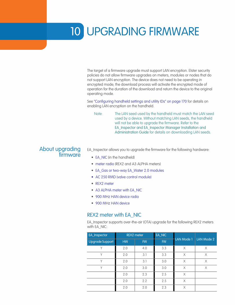
10 UPGRADING FIRMWARE
The target of a firmware upgrade must support LAN encryption. Elster security policies do not allow firmware upgrades on meters, modules or nodes that do not support LAN encryption. The device does not need to be operating in encrypted mode; the download process will activate the encrypted mode of operation for the duration of the download and return the device to the original operating mode.
See “Configuring handheld settings and utility IDs” on page 170 for details on enabling LAN encryption on the handheld.
Note: The LAN seed used by the handheld must match the LAN seed used by a device. Without matching LAN seeds, the handheld will not be able to upgrade the firmware. Refer to the EA_Inspector and EA_Inspector Manager Installation and Administration Guide for details on downloading LAN seeds.
About upgradingfirmware
EA_Inspector allows you to upgrade the firmware for the following hardware:
• EA_NIC (in the handheld)
• meter radio (REX2 and A3 ALPHA meters)
• EA_Gas or two-way EA_Water 2.0 modules
• AC 250 RMD (valve control module)
• REX2 meter
• A3 ALPHA meter with EA_NIC
• 900 MHz HAN device radio
• 900 MHz HAN device
REX2 meter with EA_NICEA_Inspector supports over-the-air (OTA) upgrade for the following REX2 meters with EA_NIC:
EA_Inspector REX2 meter EA_NICLAN Mode 1 LAN Mode 2
Upgrade Support HW FW FW
Y 2.0 4.0 3.3 X X
Y 2.0 3.1 3.3 X X
Y 2.0 3.1 3.0 X X
Y 2.0 3.0 3.0 X X
2.0 2.3 2.5 X
2.0 2.2 2.5 X
2.0 2.0 2.3 X
EA_Inspector User Guide
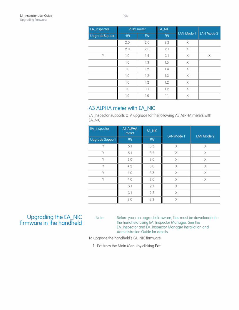
EA_Inspector User GuideUpgrading firmware
108
A3 ALPHA meter with EA_NICEA_Inspector supports OTA upgrade for the following A3 ALPHA meters with EA_NIC:
Upgrading the EA_NICfirmware in the handheld
Note: Before you can upgrade firmware, files must be downloaded to the handheld using EA_Inspector Manager. See the EA_Inspector and EA_Inspector Manager Installation and Administration Guide for details.
To upgrade the handheld’s EA_NIC firmware:
1. Exit from the Main Menu by clicking Exit.
2.0 2.0 2.2 X
2.0 2.0 2.1 X
Y 1.0 1.4 3.1 X X
1.0 1.3 1.5 X
1.0 1.2 1.4 X
1.0 1.2 1.3 X
1.0 1.2 1.2 X
1.0 1.1 1.2 X
1.0 1.0 1.1 X
EA_Inspector A3 ALPHA meter
EA_NIC
LAN Mode 1 LAN Mode 2Upgrade Support FW FW
Y 5.1 3.3 X X
Y 5.1 3.2 X X
Y 5.0 3.0 X X
Y 4.2 3.0 X X
Y 4.0 3.3 X X
Y 4.0 3.0 X X
3.1 2.7 X
3.1 2.5 X
3.0 2.3 X
EA_Inspector REX2 meter EA_NICLAN Mode 1 LAN Mode 2
Upgrade Support HW FW FW
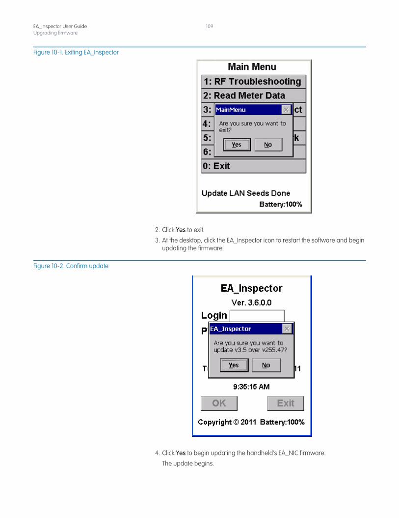
EA_Inspector User GuideUpgrading firmware
109
Figure 10-1. Exiting EA_Inspector
2. Click Yes to exit.
3. At the desktop, click the EA_Inspector icon to restart the software and begin updating the firmware.
Figure 10-2. Confirm update
4. Click Yes to begin updating the handheld’s EA_NIC firmware.
The update begins.
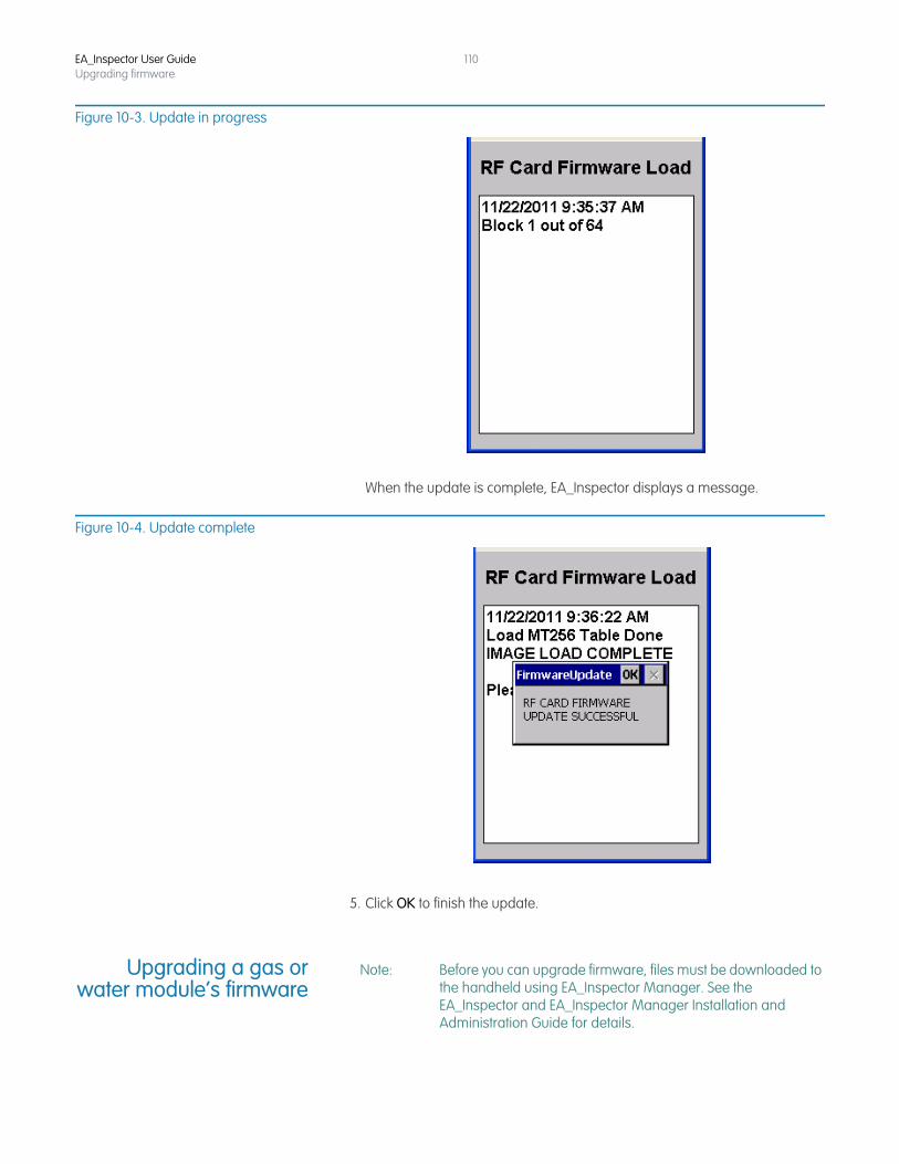
EA_Inspector User GuideUpgrading firmware
110
Figure 10-3. Update in progress
When the update is complete, EA_Inspector displays a message.
Figure 10-4. Update complete
5. Click OK to finish the update.
Upgrading a gas orwater module’s firmware
Note: Before you can upgrade firmware, files must be downloaded to the handheld using EA_Inspector Manager. See the EA_Inspector and EA_Inspector Manager Installation and Administration Guide for details.
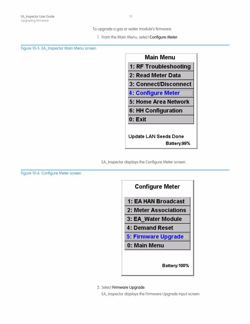
EA_Inspector User GuideUpgrading firmware
111
To upgrade a gas or water module’s firmware:
1. From the Main Menu, select Configure Meter.
Figure 10-5. EA_Inspector Main Menu screen
EA_Inspector displays the Configure Meter screen.
Figure 10-6. Configure Meter screen
2. Select Firmware Upgrade.
EA_Inspector displays the Firmware Upgrade input screen.
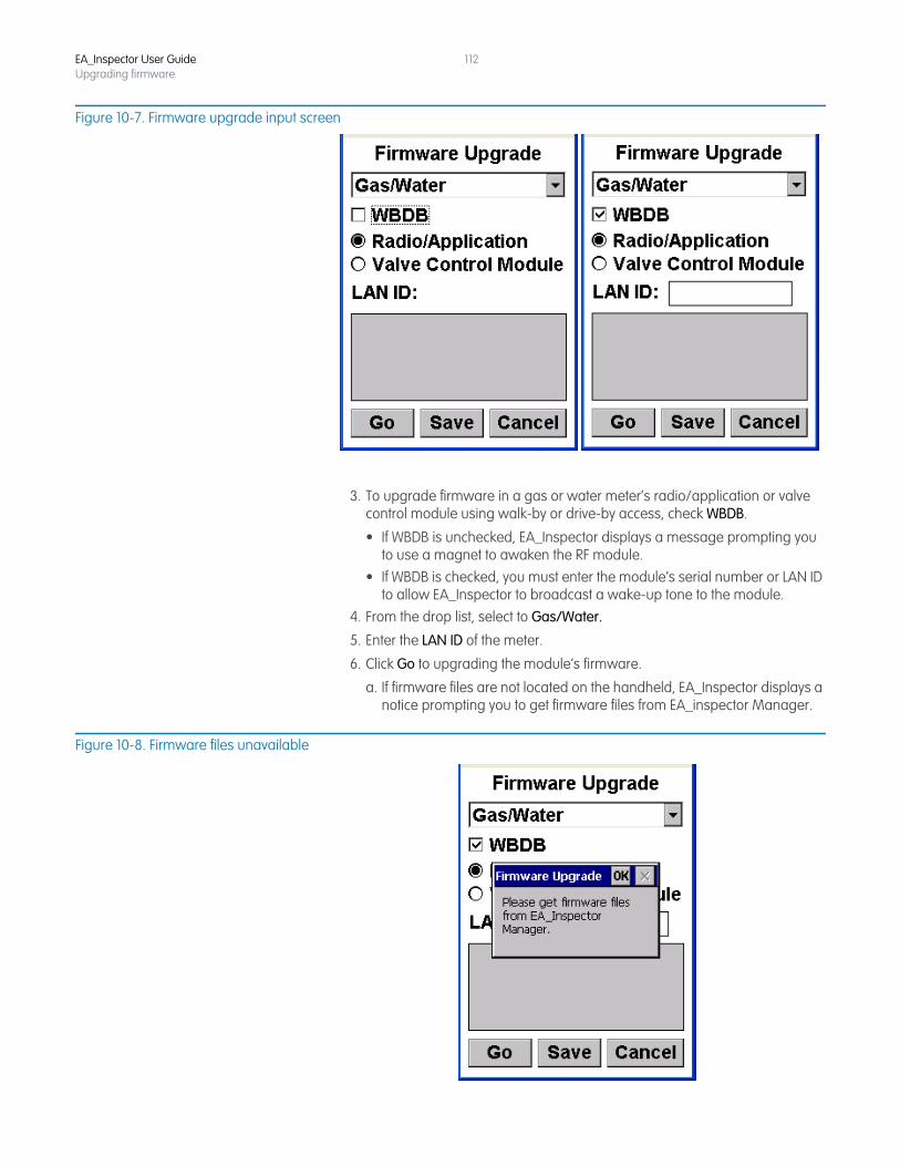
EA_Inspector User GuideUpgrading firmware
112
Figure 10-7. Firmware upgrade input screen
3. To upgrade firmware in a gas or water meter’s radio/application or valve control module using walk-by or drive-by access, check WBDB.
• If WBDB is unchecked, EA_Inspector displays a message prompting you to use a magnet to awaken the RF module.
• If WBDB is checked, you must enter the module’s serial number or LAN ID to allow EA_Inspector to broadcast a wake-up tone to the module.
4. From the drop list, select to Gas/Water.
5. Enter the LAN ID of the meter.
6. Click Go to upgrading the module’s firmware.
a. If firmware files are not located on the handheld, EA_Inspector displays a notice prompting you to get firmware files from EA_inspector Manager.
Figure 10-8. Firmware files unavailable
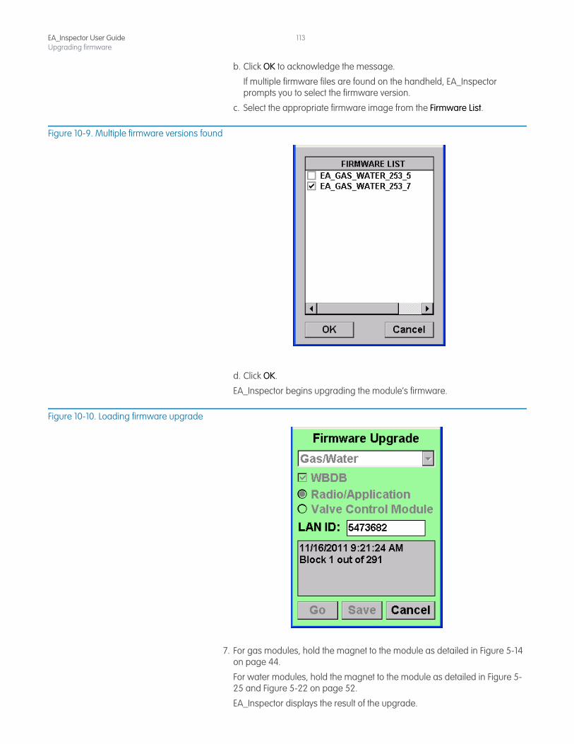
EA_Inspector User GuideUpgrading firmware
113
b. Click OK to acknowledge the message.
If multiple firmware files are found on the handheld, EA_Inspector prompts you to select the firmware version.
c. Select the appropriate firmware image from the Firmware List.
Figure 10-9. Multiple firmware versions found
d. Click OK.
EA_Inspector begins upgrading the module’s firmware.
Figure 10-10. Loading firmware upgrade
7. For gas modules, hold the magnet to the module as detailed in Figure 5-14 on page 44.
For water modules, hold the magnet to the module as detailed in Figure 5-25 and Figure 5-22 on page 52.
EA_Inspector displays the result of the upgrade.
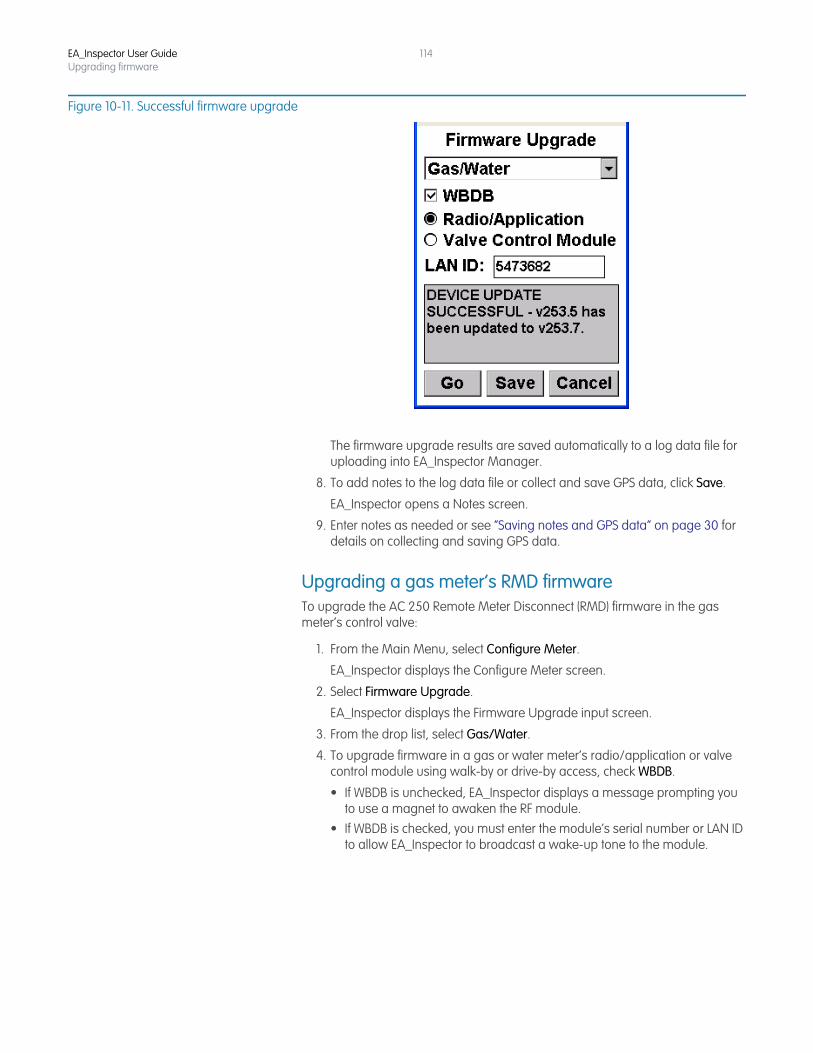
EA_Inspector User GuideUpgrading firmware
114
Figure 10-11. Successful firmware upgrade
The firmware upgrade results are saved automatically to a log data file for uploading into EA_Inspector Manager.
8. To add notes to the log data file or collect and save GPS data, click Save.
EA_Inspector opens a Notes screen.
9. Enter notes as needed or see “Saving notes and GPS data” on page 30 for details on collecting and saving GPS data.
Upgrading a gas meter’s RMD firmwareTo upgrade the AC 250 Remote Meter Disconnect (RMD) firmware in the gas meter’s control valve:
1. From the Main Menu, select Configure Meter.
EA_Inspector displays the Configure Meter screen.
2. Select Firmware Upgrade.
EA_Inspector displays the Firmware Upgrade input screen.
3. From the drop list, select Gas/Water.
4. To upgrade firmware in a gas or water meter’s radio/application or valve control module using walk-by or drive-by access, check WBDB.
• If WBDB is unchecked, EA_Inspector displays a message prompting you to use a magnet to awaken the RF module.
• If WBDB is checked, you must enter the module’s serial number or LAN ID to allow EA_Inspector to broadcast a wake-up tone to the module.
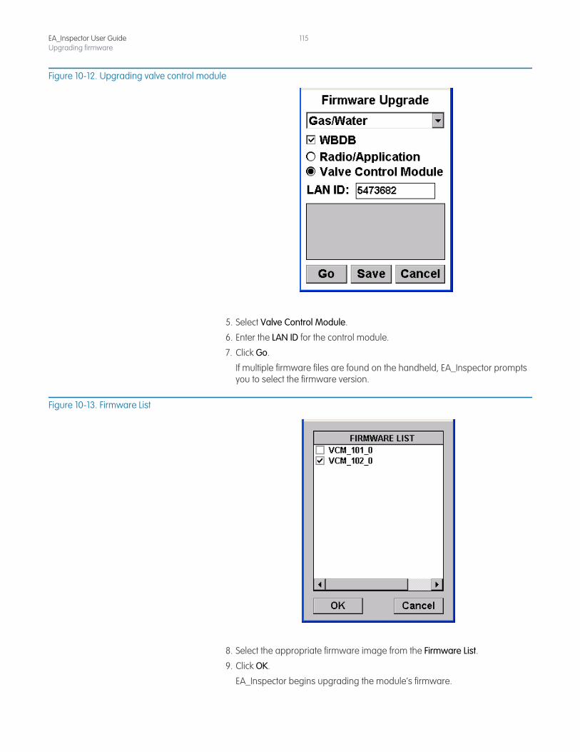
EA_Inspector User GuideUpgrading firmware
115
Figure 10-12. Upgrading valve control module
5. Select Valve Control Module.
6. Enter the LAN ID for the control module.
7. Click Go.
If multiple firmware files are found on the handheld, EA_Inspector prompts you to select the firmware version.
Figure 10-13. Firmware List
8. Select the appropriate firmware image from the Firmware List.
9. Click OK.
EA_Inspector begins upgrading the module’s firmware.
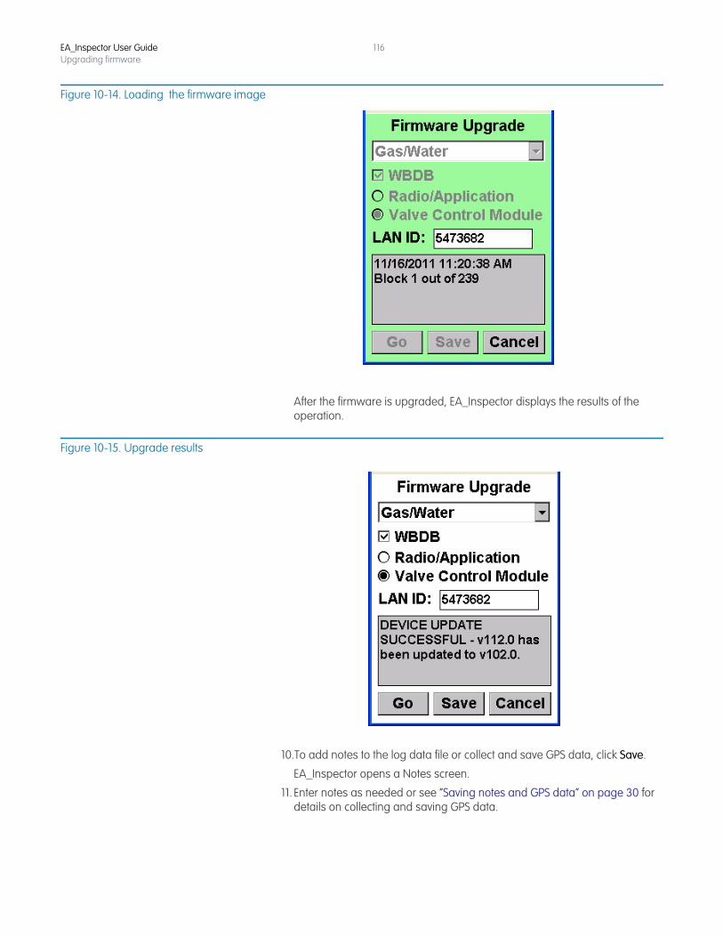
EA_Inspector User GuideUpgrading firmware
116
Figure 10-14. Loading the firmware image
After the firmware is upgraded, EA_Inspector displays the results of the operation.
Figure 10-15. Upgrade results
10.To add notes to the log data file or collect and save GPS data, click Save.
EA_Inspector opens a Notes screen.
11. Enter notes as needed or see “Saving notes and GPS data” on page 30 for details on collecting and saving GPS data.
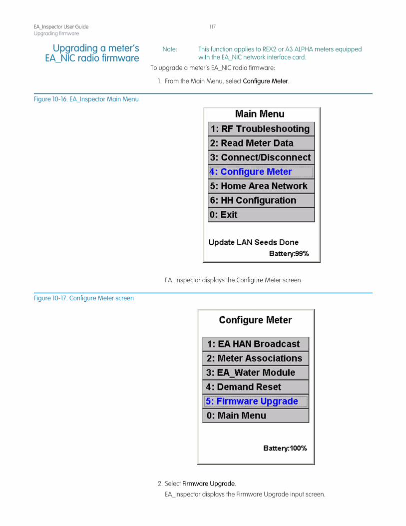
EA_Inspector User GuideUpgrading firmware
117
Upgrading a meter’sEA_NIC radio firmware
Note: This function applies to REX2 or A3 ALPHA meters equipped with the EA_NIC network interface card.
To upgrade a meter’s EA_NIC radio firmware:
1. From the Main Menu, select Configure Meter.
Figure 10-16. EA_Inspector Main Menu
EA_Inspector displays the Configure Meter screen.
Figure 10-17. Configure Meter screen
2. Select Firmware Upgrade.
EA_Inspector displays the Firmware Upgrade input screen.
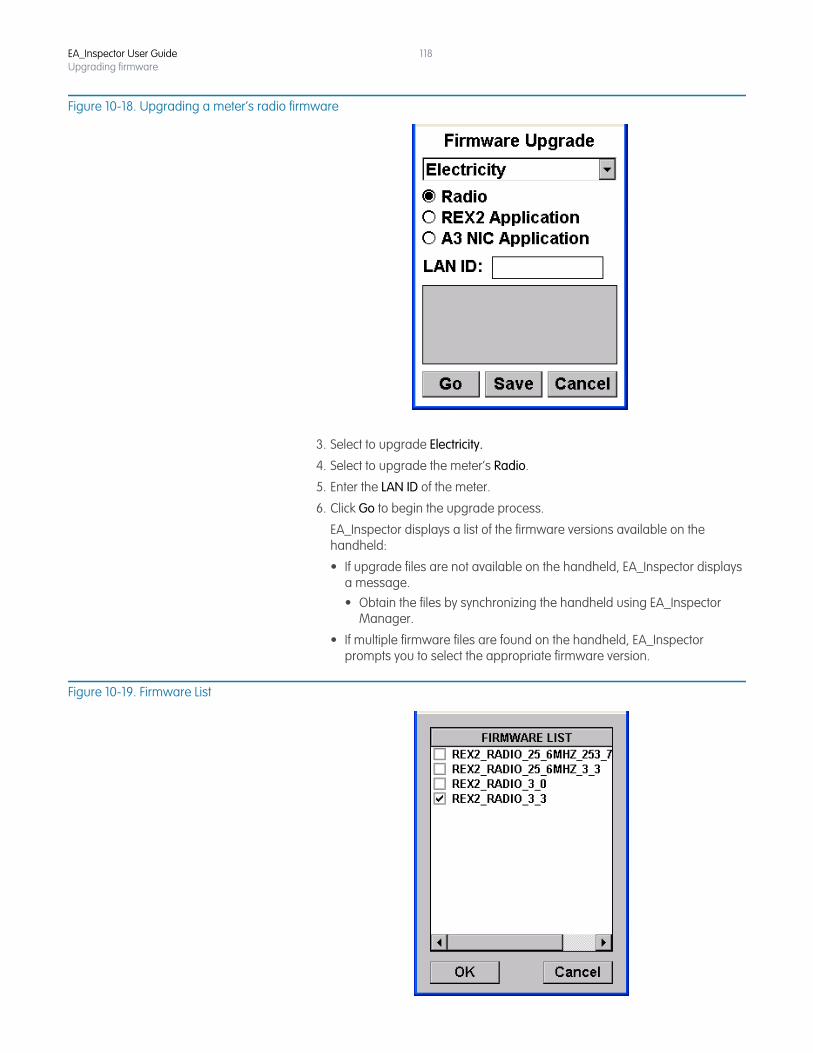
EA_Inspector User GuideUpgrading firmware
118
Figure 10-18. Upgrading a meter’s radio firmware
3. Select to upgrade Electricity.
4. Select to upgrade the meter’s Radio.
5. Enter the LAN ID of the meter.
6. Click Go to begin the upgrade process.
EA_Inspector displays a list of the firmware versions available on the handheld:
• If upgrade files are not available on the handheld, EA_Inspector displays a message.• Obtain the files by synchronizing the handheld using EA_Inspector
Manager.
• If multiple firmware files are found on the handheld, EA_Inspector prompts you to select the appropriate firmware version.
Figure 10-19. Firmware List
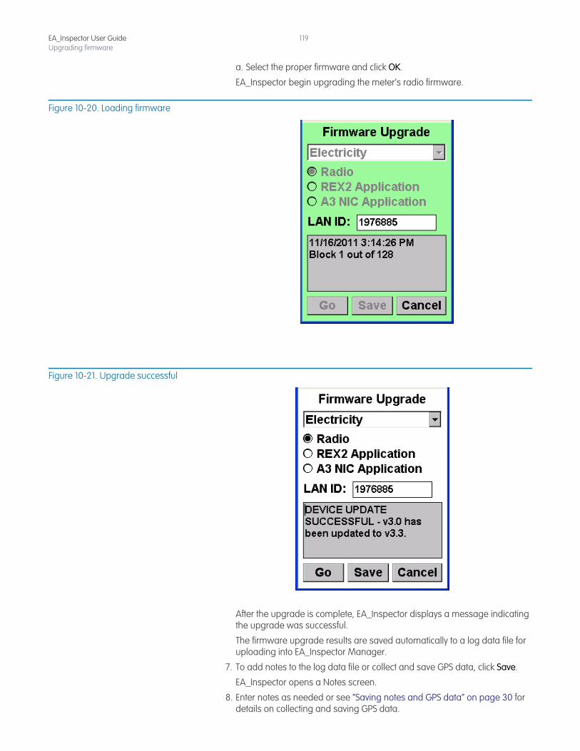
EA_Inspector User GuideUpgrading firmware
119
a. Select the proper firmware and click OK.
EA_Inspector begin upgrading the meter’s radio firmware.
Figure 10-20. Loading firmware
Figure 10-21. Upgrade successful
After the upgrade is complete, EA_Inspector displays a message indicating the upgrade was successful.
The firmware upgrade results are saved automatically to a log data file for uploading into EA_Inspector Manager.
7. To add notes to the log data file or collect and save GPS data, click Save.
EA_Inspector opens a Notes screen.
8. Enter notes as needed or see “Saving notes and GPS data” on page 30 for details on collecting and saving GPS data.
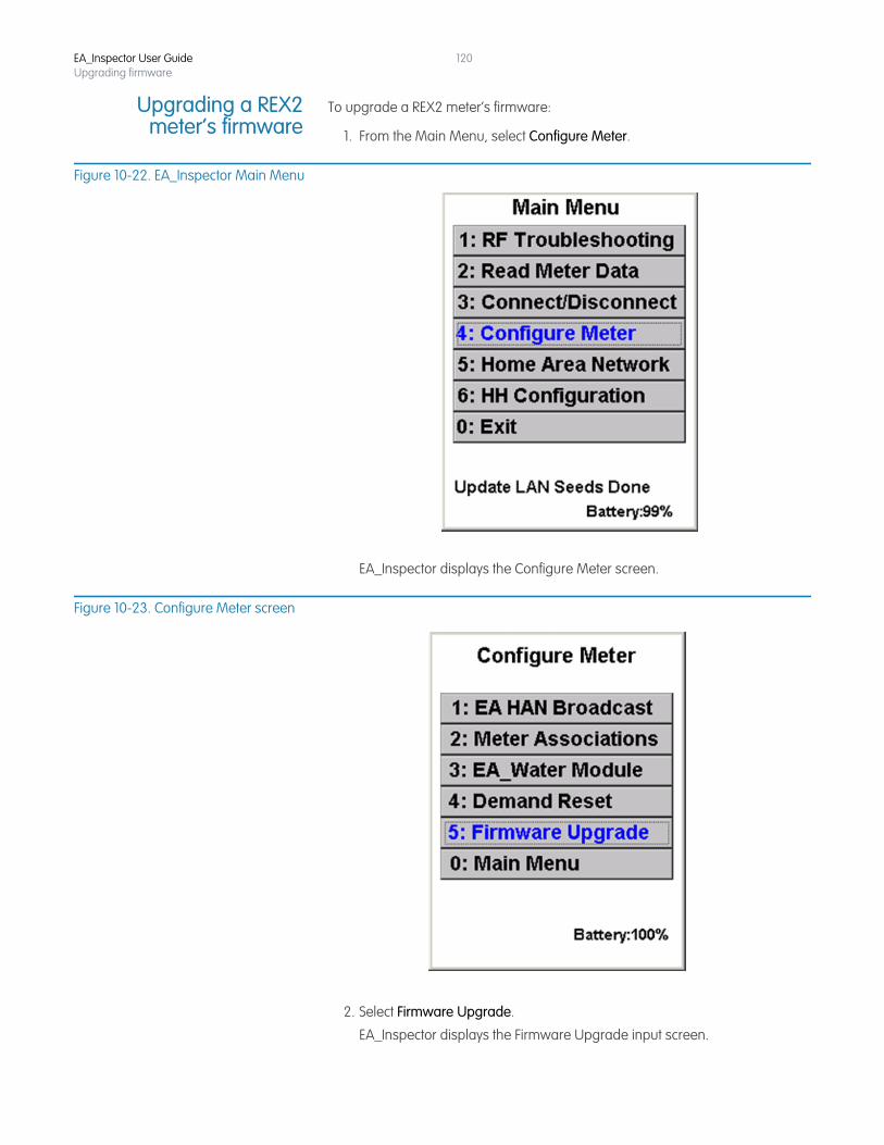
EA_Inspector User GuideUpgrading firmware
120
Upgrading a REX2meter’s firmware
To upgrade a REX2 meter’s firmware:
1. From the Main Menu, select Configure Meter.
Figure 10-22. EA_Inspector Main Menu
EA_Inspector displays the Configure Meter screen.
Figure 10-23. Configure Meter screen
2. Select Firmware Upgrade.
EA_Inspector displays the Firmware Upgrade input screen.
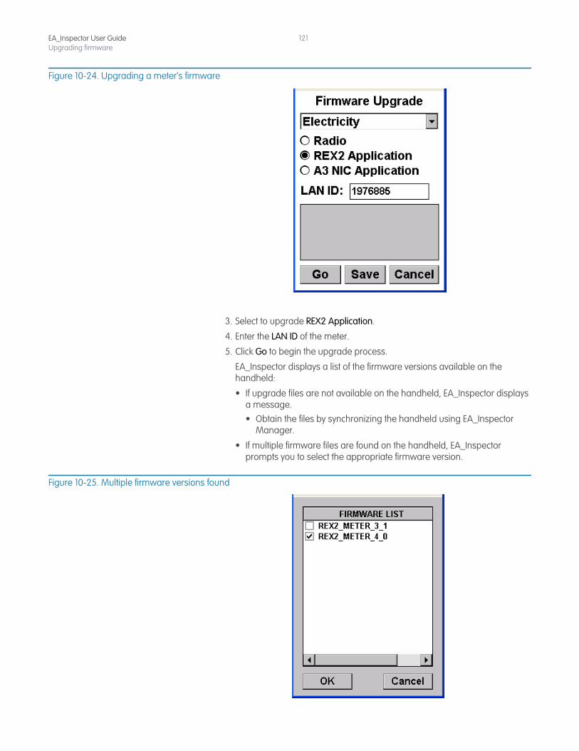
EA_Inspector User GuideUpgrading firmware
121
Figure 10-24. Upgrading a meter’s firmware
3. Select to upgrade REX2 Application.
4. Enter the LAN ID of the meter.
5. Click Go to begin the upgrade process.
EA_Inspector displays a list of the firmware versions available on the handheld:
• If upgrade files are not available on the handheld, EA_Inspector displays a message.• Obtain the files by synchronizing the handheld using EA_Inspector
Manager.
• If multiple firmware files are found on the handheld, EA_Inspector prompts you to select the appropriate firmware version.
Figure 10-25. Multiple firmware versions found
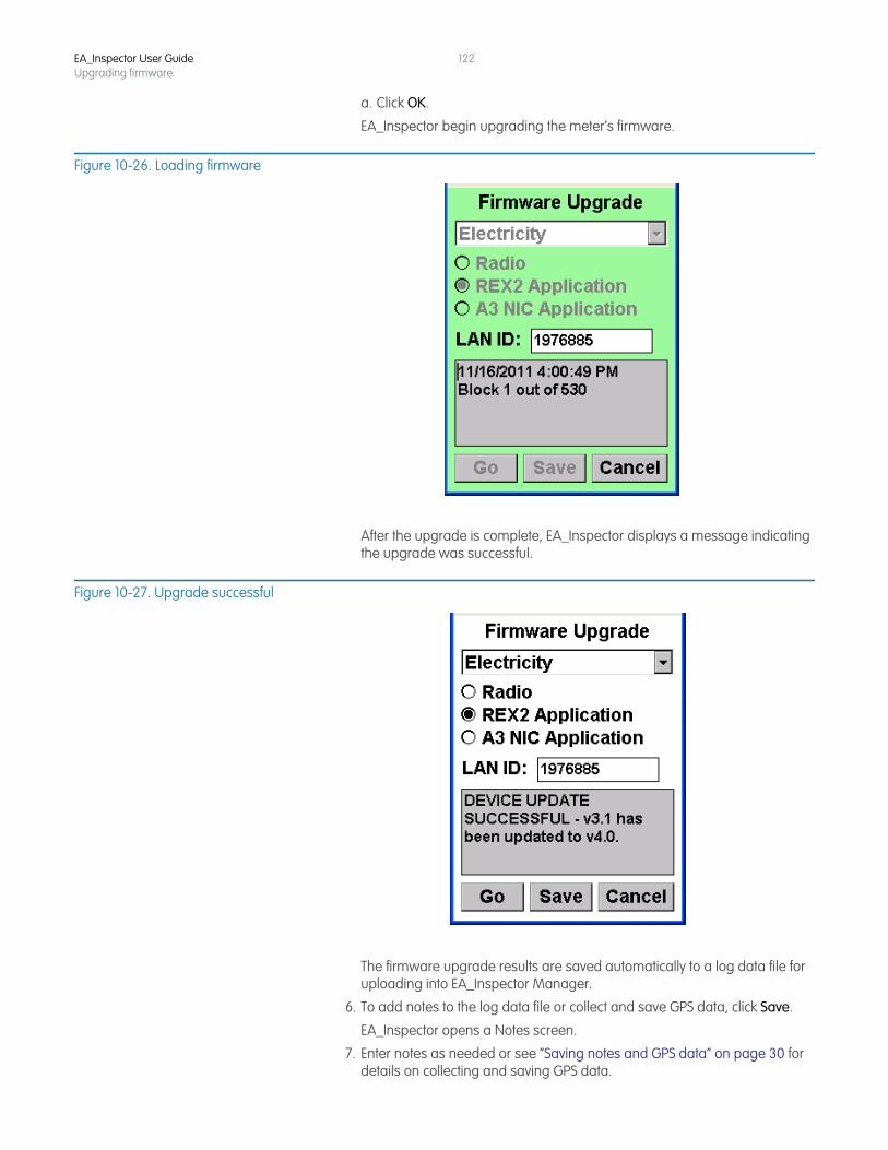
EA_Inspector User GuideUpgrading firmware
122
a. Click OK.
EA_Inspector begin upgrading the meter’s firmware.
Figure 10-26. Loading firmware
After the upgrade is complete, EA_Inspector displays a message indicating the upgrade was successful.
Figure 10-27. Upgrade successful
The firmware upgrade results are saved automatically to a log data file for uploading into EA_Inspector Manager.
6. To add notes to the log data file or collect and save GPS data, click Save.
EA_Inspector opens a Notes screen.
7. Enter notes as needed or see “Saving notes and GPS data” on page 30 for details on collecting and saving GPS data.
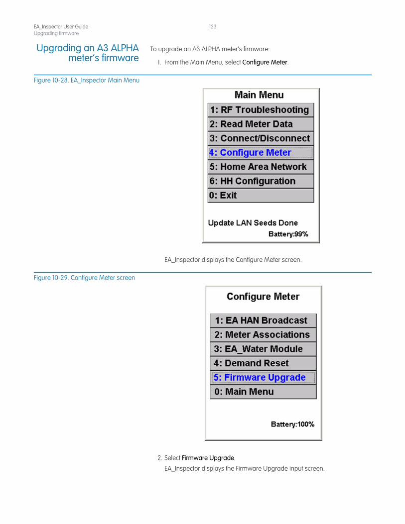
EA_Inspector User GuideUpgrading firmware
123
Upgrading an A3 ALPHAmeter’s firmware
To upgrade an A3 ALPHA meter’s firmware:
1. From the Main Menu, select Configure Meter.
Figure 10-28. EA_Inspector Main Menu
EA_Inspector displays the Configure Meter screen.
Figure 10-29. Configure Meter screen
2. Select Firmware Upgrade.
EA_Inspector displays the Firmware Upgrade input screen.
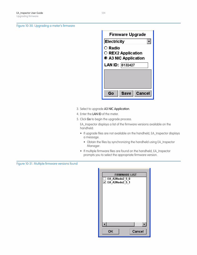
EA_Inspector User GuideUpgrading firmware
124
Figure 10-30. Upgrading a meter’s firmware
3. Select to upgrade A3 NIC Application.
4. Enter the LAN ID of the meter.
5. Click Go to begin the upgrade process.
EA_Inspector displays a list of the firmware versions available on the handheld:
• If upgrade files are not available on the handheld, EA_Inspector displays a message.• Obtain the files by synchronizing the handheld using EA_Inspector
Manager.
• If multiple firmware files are found on the handheld, EA_Inspector prompts you to select the appropriate firmware version.
Figure 10-31. Multiple firmware versions found
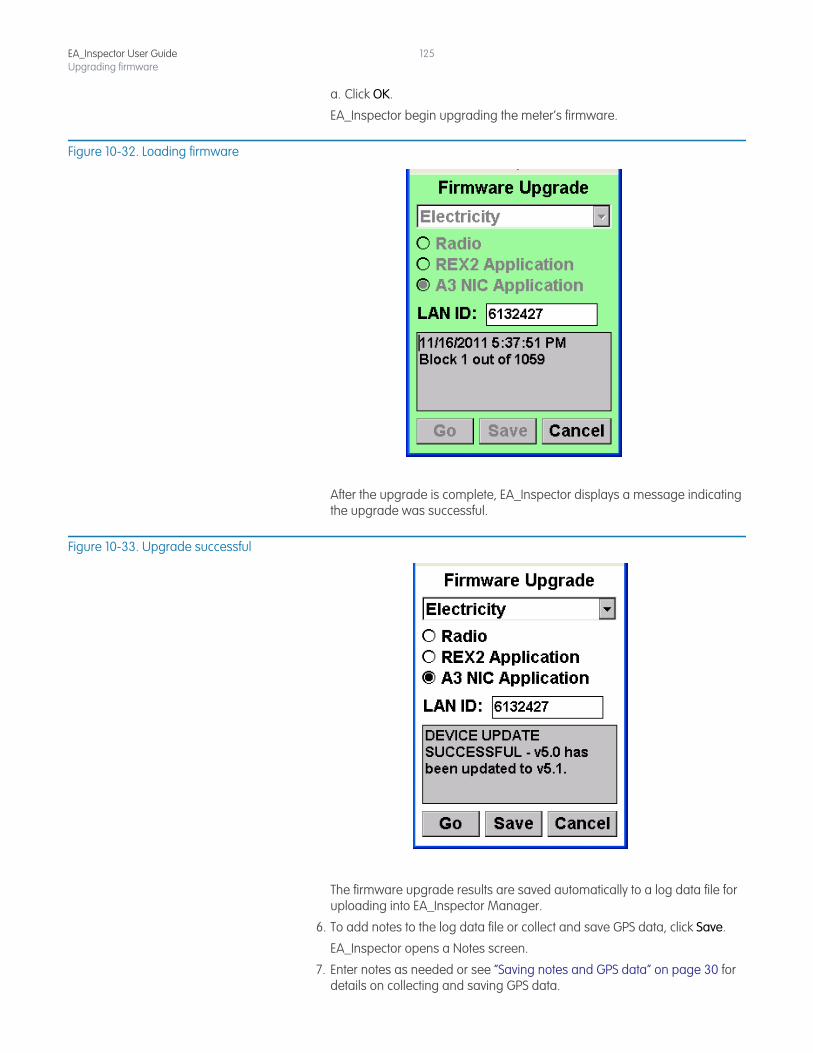
EA_Inspector User GuideUpgrading firmware
125
a. Click OK.
EA_Inspector begin upgrading the meter’s firmware.
Figure 10-32. Loading firmware
After the upgrade is complete, EA_Inspector displays a message indicating the upgrade was successful.
Figure 10-33. Upgrade successful
The firmware upgrade results are saved automatically to a log data file for uploading into EA_Inspector Manager.
6. To add notes to the log data file or collect and save GPS data, click Save.
EA_Inspector opens a Notes screen.
7. Enter notes as needed or see “Saving notes and GPS data” on page 30 for details on collecting and saving GPS data.
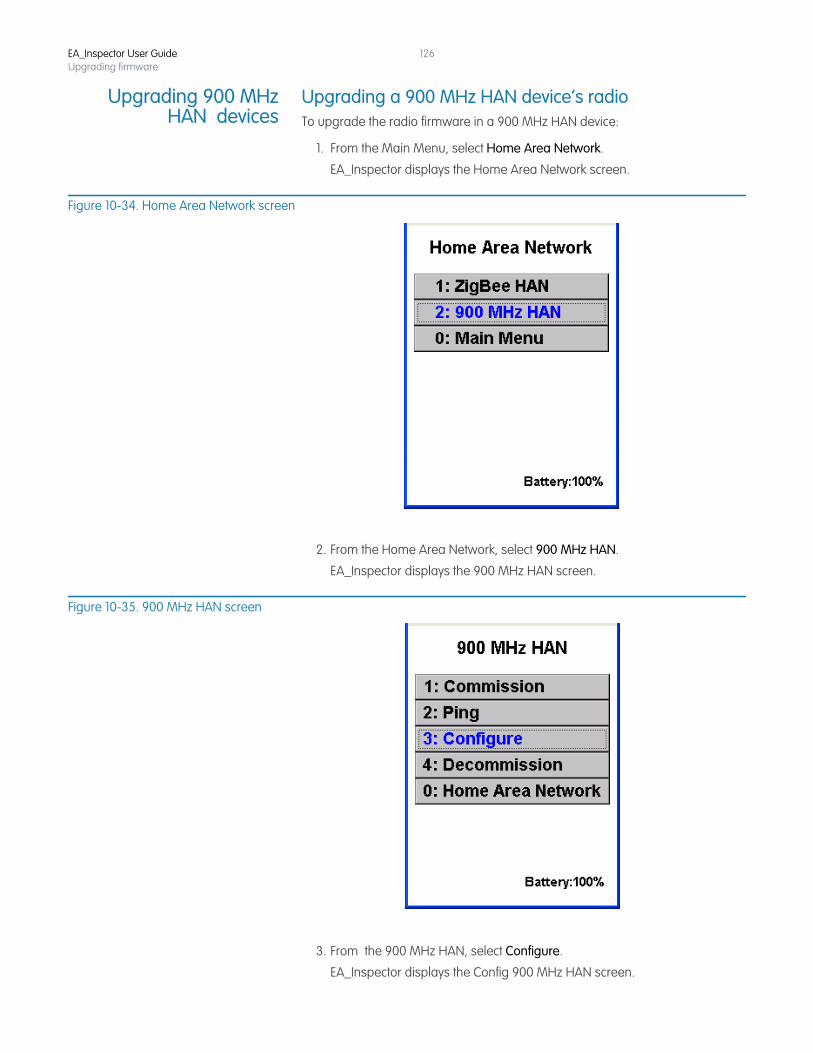
EA_Inspector User GuideUpgrading firmware
126
Upgrading 900 MHzHAN devices
Upgrading a 900 MHz HAN device’s radioTo upgrade the radio firmware in a 900 MHz HAN device:
1. From the Main Menu, select Home Area Network.
EA_Inspector displays the Home Area Network screen.
Figure 10-34. Home Area Network screen
2. From the Home Area Network, select 900 MHz HAN.
EA_Inspector displays the 900 MHz HAN screen.
Figure 10-35. 900 MHz HAN screen
3. From the 900 MHz HAN, select Configure.
EA_Inspector displays the Config 900 MHz HAN screen.
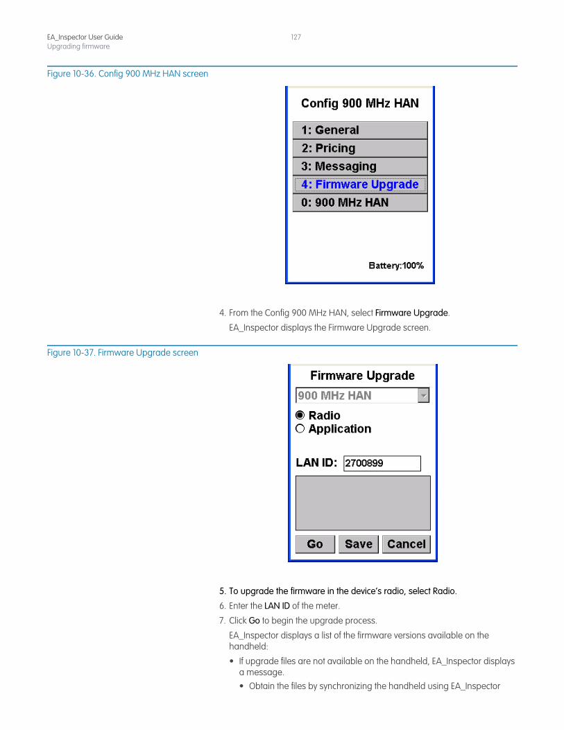
EA_Inspector User GuideUpgrading firmware
127
Figure 10-36. Config 900 MHz HAN screen
4. From the Config 900 MHz HAN, select Firmware Upgrade.
EA_Inspector displays the Firmware Upgrade screen.
Figure 10-37. Firmware Upgrade screen
5. To upgrade the firmware in the device’s radio, select Radio.
6. Enter the LAN ID of the meter.
7. Click Go to begin the upgrade process.
EA_Inspector displays a list of the firmware versions available on the handheld:
• If upgrade files are not available on the handheld, EA_Inspector displays a message.• Obtain the files by synchronizing the handheld using EA_Inspector
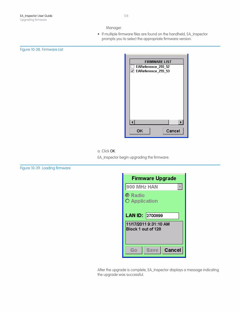
EA_Inspector User GuideUpgrading firmware
128
Manager.
• If multiple firmware files are found on the handheld, EA_Inspector prompts you to select the appropriate firmware version.
Figure 10-38. Firmware List
a. Click OK.
EA_Inspector begin upgrading the firmware.
Figure 10-39. Loading firmware
After the upgrade is complete, EA_Inspector displays a message indicating the upgrade was successful.
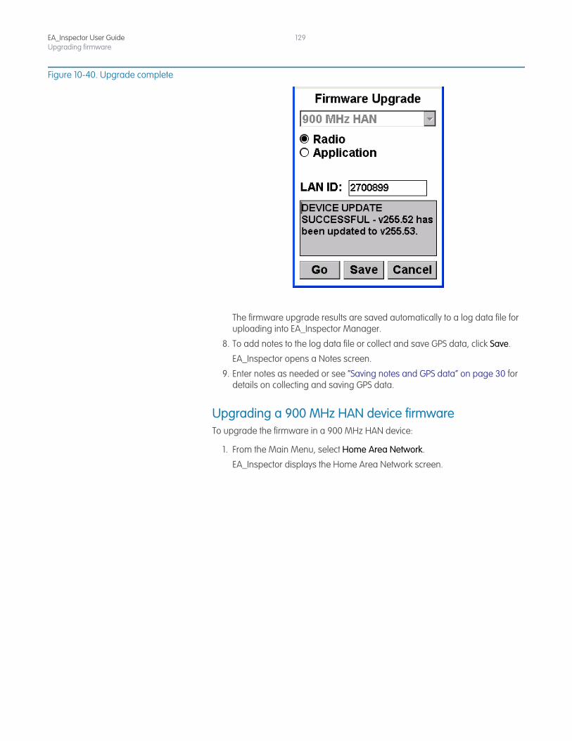
EA_Inspector User GuideUpgrading firmware
129
Figure 10-40. Upgrade complete
The firmware upgrade results are saved automatically to a log data file for uploading into EA_Inspector Manager.
8. To add notes to the log data file or collect and save GPS data, click Save.
EA_Inspector opens a Notes screen.
9. Enter notes as needed or see “Saving notes and GPS data” on page 30 for details on collecting and saving GPS data.
Upgrading a 900 MHz HAN device firmwareTo upgrade the firmware in a 900 MHz HAN device:
1. From the Main Menu, select Home Area Network.
EA_Inspector displays the Home Area Network screen.
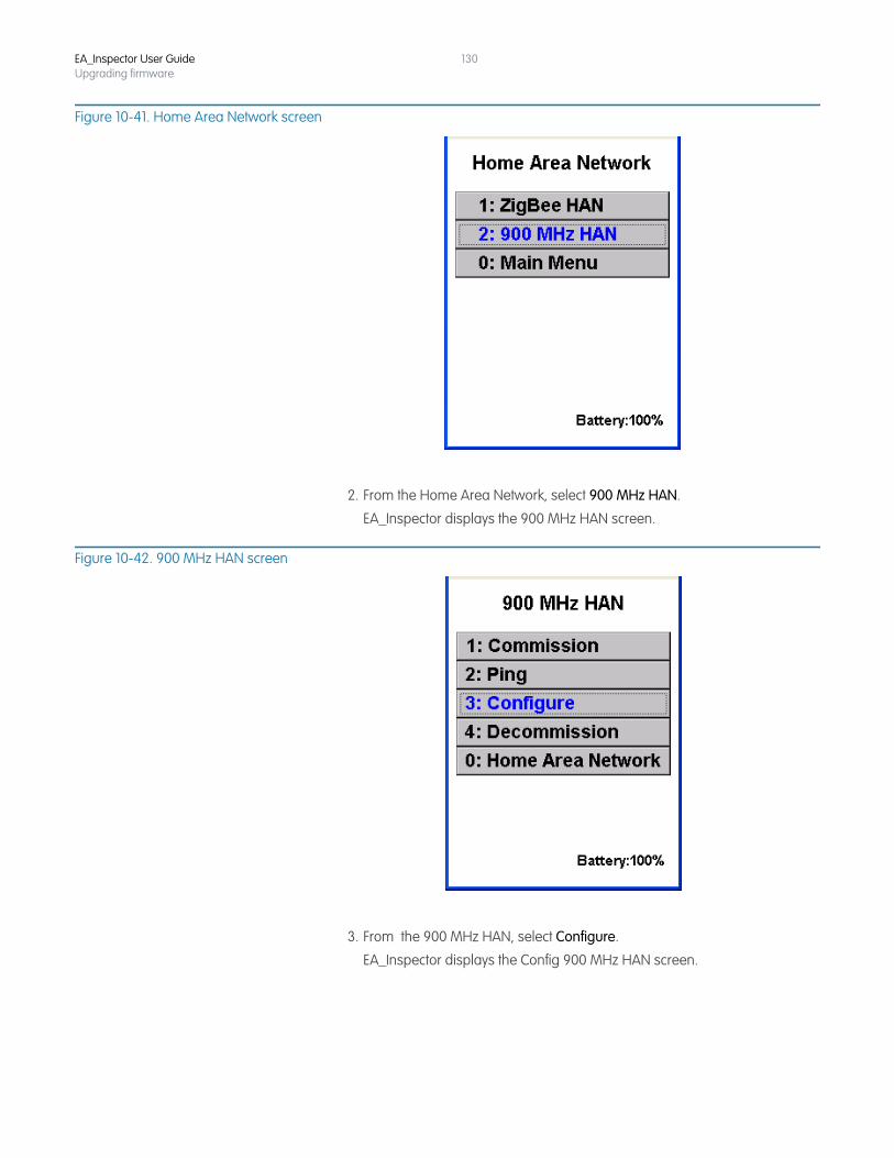
EA_Inspector User GuideUpgrading firmware
130
Figure 10-41. Home Area Network screen
2. From the Home Area Network, select 900 MHz HAN.
EA_Inspector displays the 900 MHz HAN screen.
Figure 10-42. 900 MHz HAN screen
3. From the 900 MHz HAN, select Configure.
EA_Inspector displays the Config 900 MHz HAN screen.
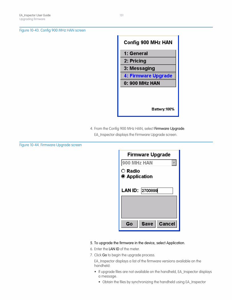
EA_Inspector User GuideUpgrading firmware
131
Figure 10-43. Config 900 MHz HAN screen
4. From the Config 900 MHz HAN, select Firmware Upgrade.
EA_Inspector displays the Firmware Upgrade screen.
Figure 10-44. Firmware Upgrade screen
5. To upgrade the firmware in the device, select Application.
6. Enter the LAN ID of the meter.
7. Click Go to begin the upgrade process.
EA_Inspector displays a list of the firmware versions available on the handheld:
• If upgrade files are not available on the handheld, EA_Inspector displays a message.• Obtain the files by synchronizing the handheld using EA_Inspector
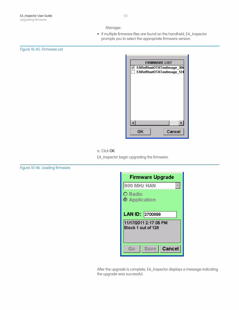
EA_Inspector User GuideUpgrading firmware
132
Manager.
• If multiple firmware files are found on the handheld, EA_Inspector prompts you to select the appropriate firmware version.
Figure 10-45. Firmware List
a. Click OK.
EA_Inspector begin upgrading the firmware.
Figure 10-46. Loading firmware
After the upgrade is complete, EA_Inspector displays a message indicating the upgrade was successful.
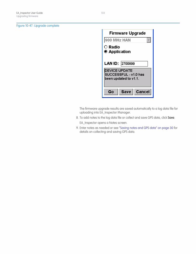
EA_Inspector User GuideUpgrading firmware
133
Figure 10-47. Upgrade complete
The firmware upgrade results are saved automatically to a log data file for uploading into EA_Inspector Manager.
8. To add notes to the log data file or collect and save GPS data, click Save.
EA_Inspector opens a Notes screen.
9. Enter notes as needed or see “Saving notes and GPS data” on page 30 for details on collecting and saving GPS data.
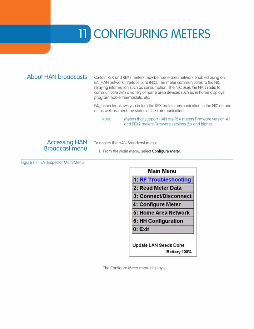
11 CONFIGURING METERS
About HAN broadcasts Certain REX and REX2 meters may be home area network enabled using an EA_HAN network interface card (NIC). The meter communicates to the NIC relaying information such as consumption. The NIC uses the HAN radio to communicate with a variety of home area devices such as in home displays, programmable thermostats, etc.
EA_Inspector allows you to turn the REX meter communication to the NIC on and off as well as check the status of the communication.
Note: Meters that support HAN are REX meters Firmware version 4.1 and REX2 meters Firmware versions 2.x and higher.
Accessing HANBroadcast menu
To access the HAN Broadcast menu:
1. From the Main Menu, select Configure Meter.
Figure 11-1. EA_Inspector Main Menu
The Configure Meter menu displays.
EA_Inspector User Guide
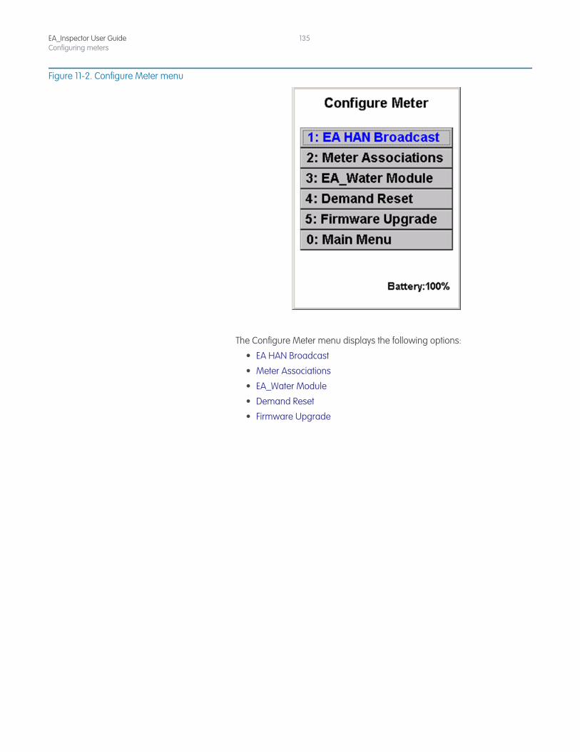
EA_Inspector User GuideConfiguring meters
135
Figure 11-2. Configure Meter menu
The Configure Meter menu displays the following options:
• EA HAN Broadcast
• Meter Associations
• EA_Water Module
• Demand Reset
• Firmware Upgrade
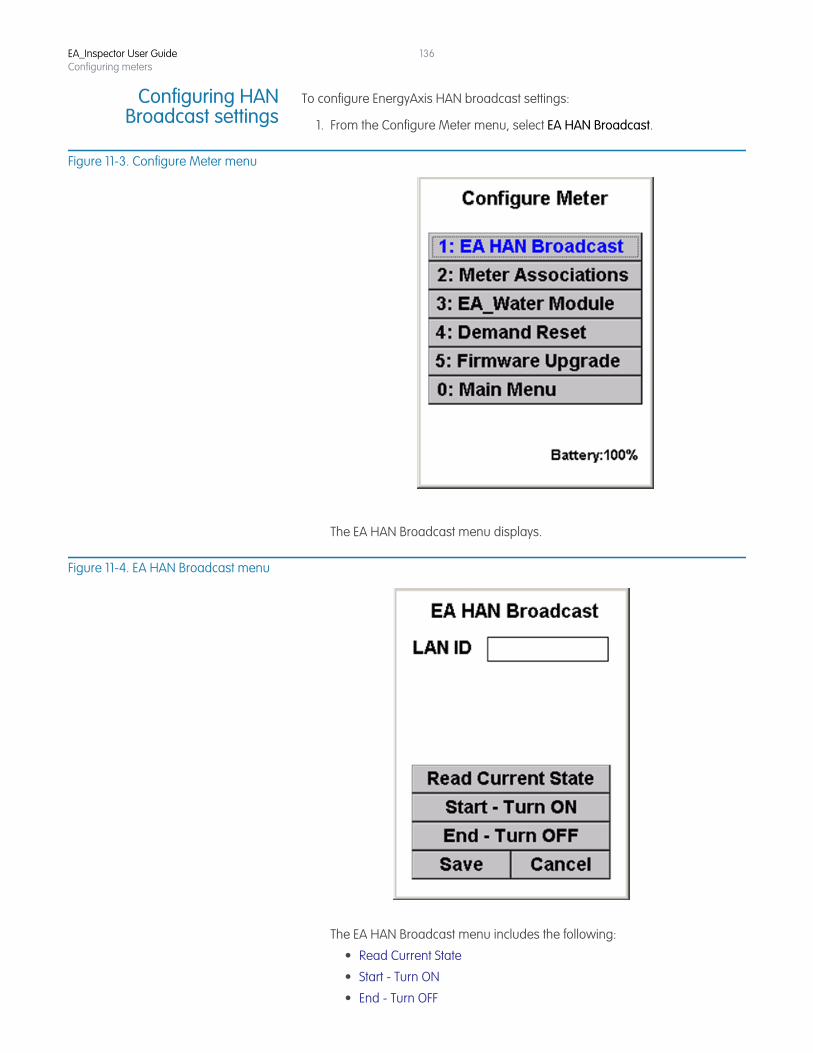
EA_Inspector User GuideConfiguring meters
136
Configuring HANBroadcast settings
To configure EnergyAxis HAN broadcast settings:
1. From the Configure Meter menu, select EA HAN Broadcast.
Figure 11-3. Configure Meter menu
The EA HAN Broadcast menu displays.
Figure 11-4. EA HAN Broadcast menu
The EA HAN Broadcast menu includes the following:
• Read Current State
• Start - Turn ON
• End - Turn OFF
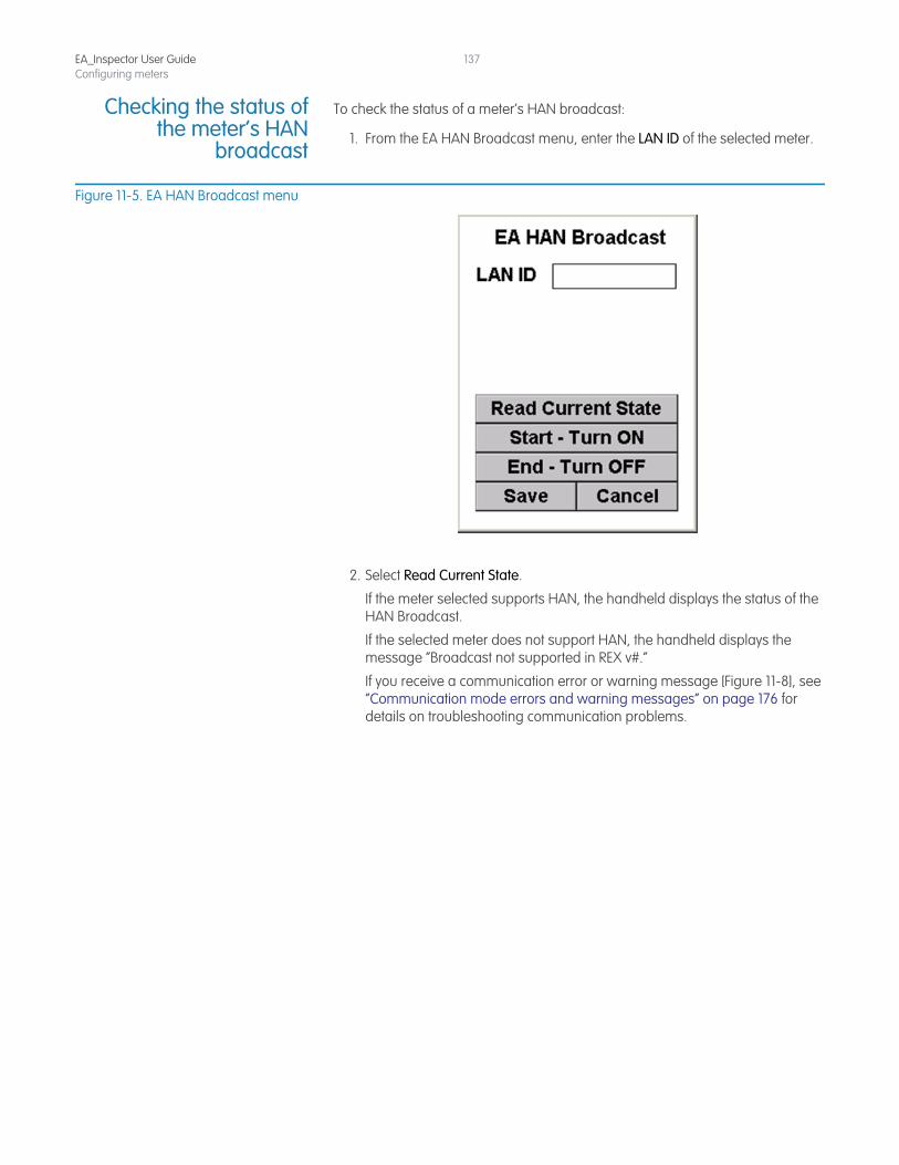
EA_Inspector User GuideConfiguring meters
137
Checking the status ofthe meter’s HAN
broadcast
To check the status of a meter’s HAN broadcast:
1. From the EA HAN Broadcast menu, enter the LAN ID of the selected meter.
Figure 11-5. EA HAN Broadcast menu
2. Select Read Current State.
If the meter selected supports HAN, the handheld displays the status of the HAN Broadcast.
If the selected meter does not support HAN, the handheld displays the message “Broadcast not supported in REX v#.”
If you receive a communication error or warning message [Figure 11-8], see “Communication mode errors and warning messages” on page 176 for details on troubleshooting communication problems.
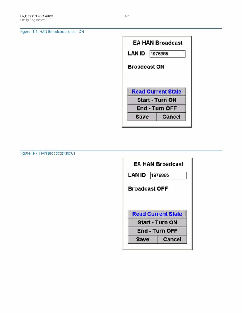
EA_Inspector User GuideConfiguring meters
138
Figure 11-6. HAN Broadcast status - ON
Figure 11-7. HAN Broadcast status
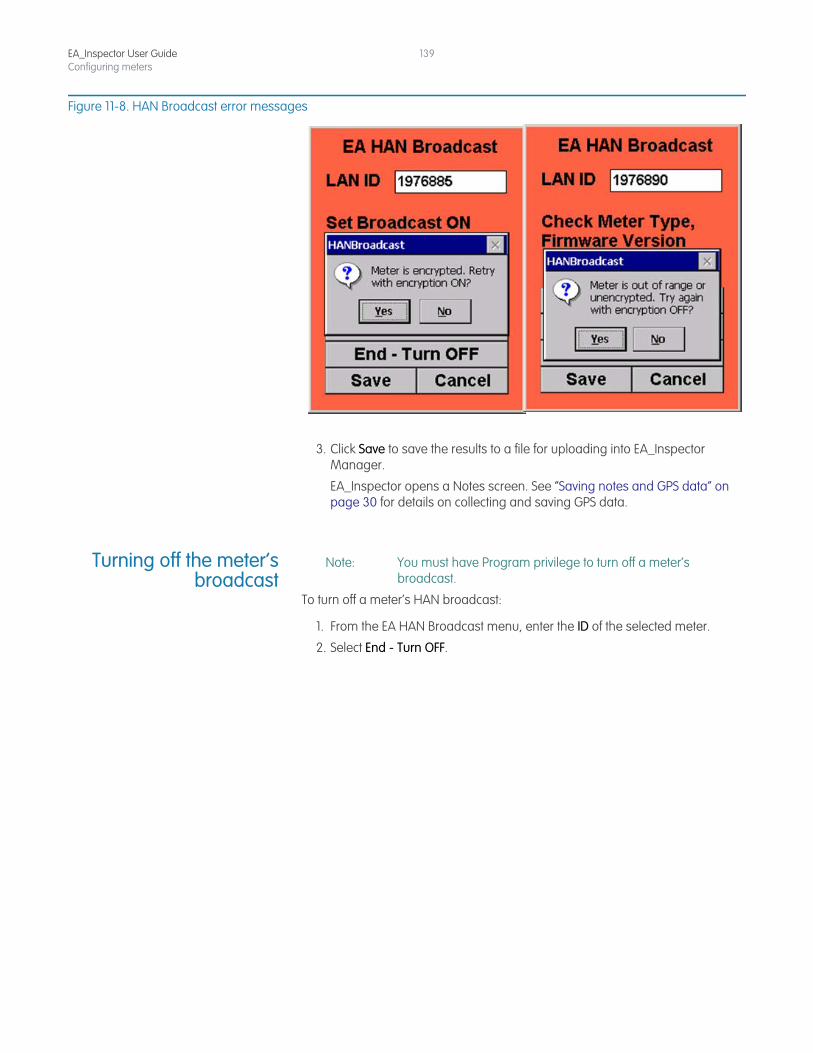
EA_Inspector User GuideConfiguring meters
139
Figure 11-8. HAN Broadcast error messages
3. Click Save to save the results to a file for uploading into EA_Inspector Manager.
EA_Inspector opens a Notes screen. See “Saving notes and GPS data” on page 30 for details on collecting and saving GPS data.
Turning off the meter’sbroadcast
Note: You must have Program privilege to turn off a meter’s broadcast.
To turn off a meter’s HAN broadcast:
1. From the EA HAN Broadcast menu, enter the ID of the selected meter.
2. Select End - Turn OFF.
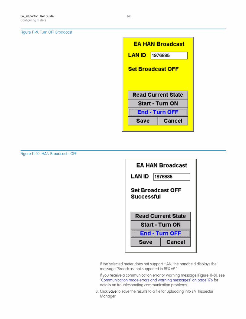
EA_Inspector User GuideConfiguring meters
140
Figure 11-9. Turn OFF Broadcast
Figure 11-10. HAN Broadcast - OFF
If the selected meter does not support HAN, the handheld displays the message “Broadcast not supported in REX v#.”
If you receive a communication error or warning message [Figure 11-8], see “Communication mode errors and warning messages” on page 176 for details on troubleshooting communication problems.
3. Click Save to save the results to a file for uploading into EA_Inspector Manager.
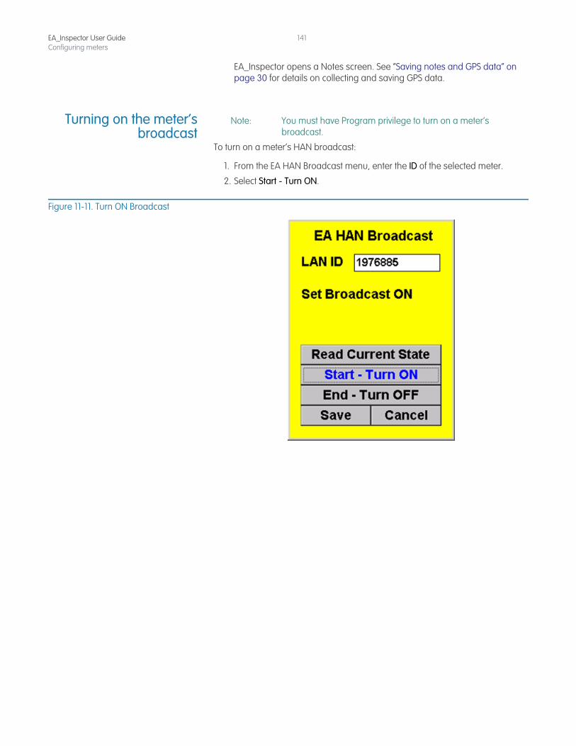
EA_Inspector User GuideConfiguring meters
141
EA_Inspector opens a Notes screen. See “Saving notes and GPS data” on page 30 for details on collecting and saving GPS data.
Turning on the meter’sbroadcast
Note: You must have Program privilege to turn on a meter’s broadcast.
To turn on a meter’s HAN broadcast:
1. From the EA HAN Broadcast menu, enter the ID of the selected meter.
2. Select Start - Turn ON.
Figure 11-11. Turn ON Broadcast
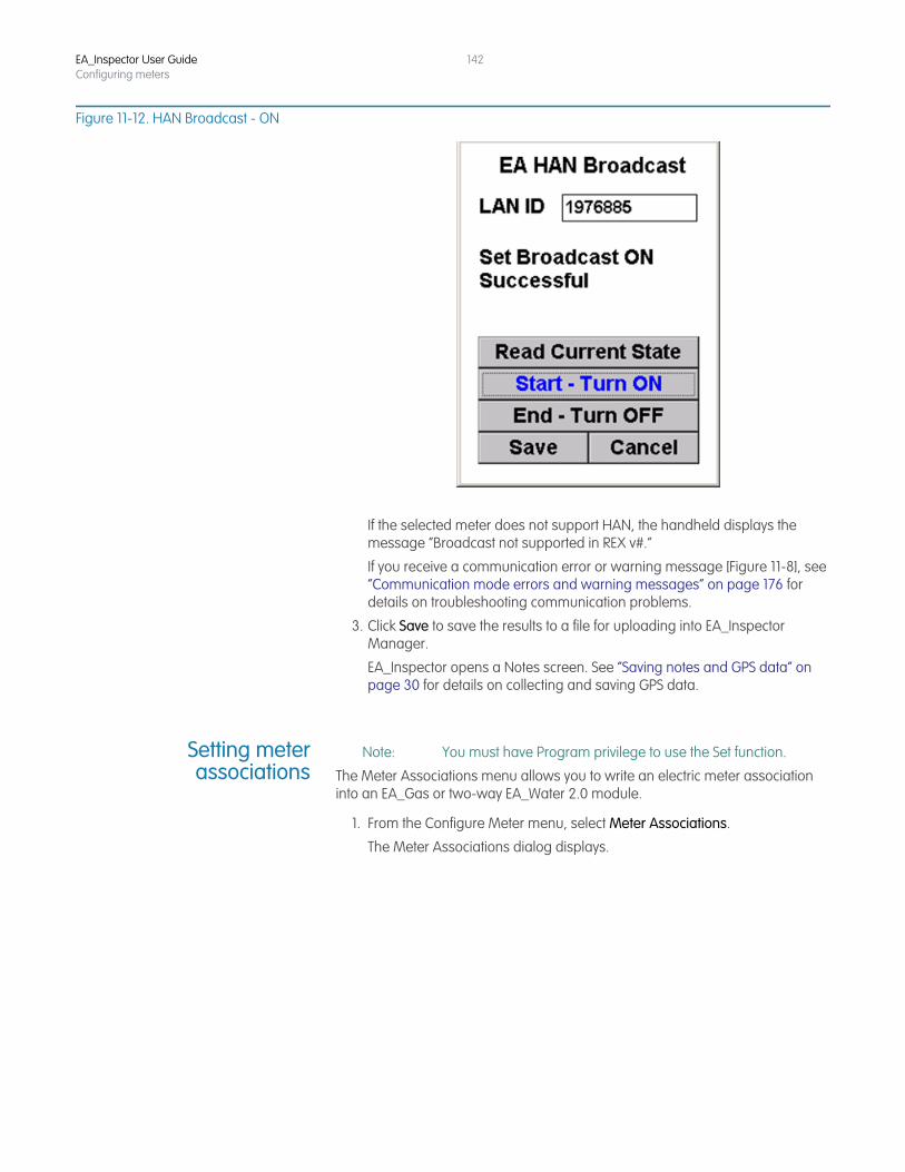
EA_Inspector User GuideConfiguring meters
142
Figure 11-12. HAN Broadcast - ON
If the selected meter does not support HAN, the handheld displays the message “Broadcast not supported in REX v#.”
If you receive a communication error or warning message [Figure 11-8], see “Communication mode errors and warning messages” on page 176 for details on troubleshooting communication problems.
3. Click Save to save the results to a file for uploading into EA_Inspector Manager.
EA_Inspector opens a Notes screen. See “Saving notes and GPS data” on page 30 for details on collecting and saving GPS data.
Setting meterassociations
Note: You must have Program privilege to use the Set function.
The Meter Associations menu allows you to write an electric meter association into an EA_Gas or two-way EA_Water 2.0 module.
1. From the Configure Meter menu, select Meter Associations.
The Meter Associations dialog displays.
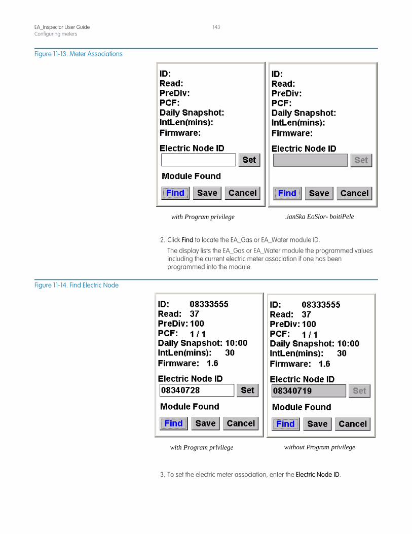
EA_Inspector User GuideConfiguring meters
143
Figure 11-13. Meter Associations
2. Click Find to locate the EA_Gas or EA_Water module ID.
The display lists the EA_Gas or EA_Water module the programmed values including the current electric meter association if one has been programmed into the module.
Figure 11-14. Find Electric Node
3. To set the electric meter association, enter the Electric Node ID.
.ianSka EoSlor- boitiPelewith Program privilege
without Program privilegewith Program privilege
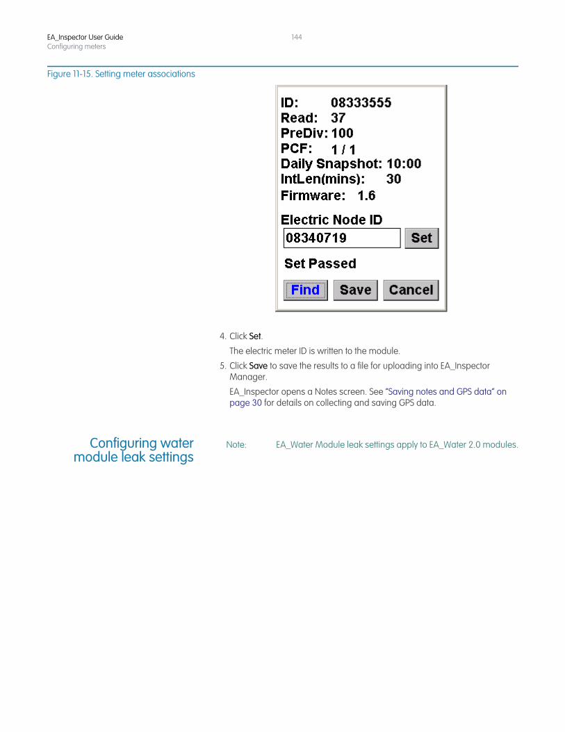
EA_Inspector User GuideConfiguring meters
144
Figure 11-15. Setting meter associations
4. Click Set.
The electric meter ID is written to the module.
5. Click Save to save the results to a file for uploading into EA_Inspector Manager.
EA_Inspector opens a Notes screen. See “Saving notes and GPS data” on page 30 for details on collecting and saving GPS data.
Configuring watermodule leak settings
Note: EA_Water Module leak settings apply to EA_Water 2.0 modules.
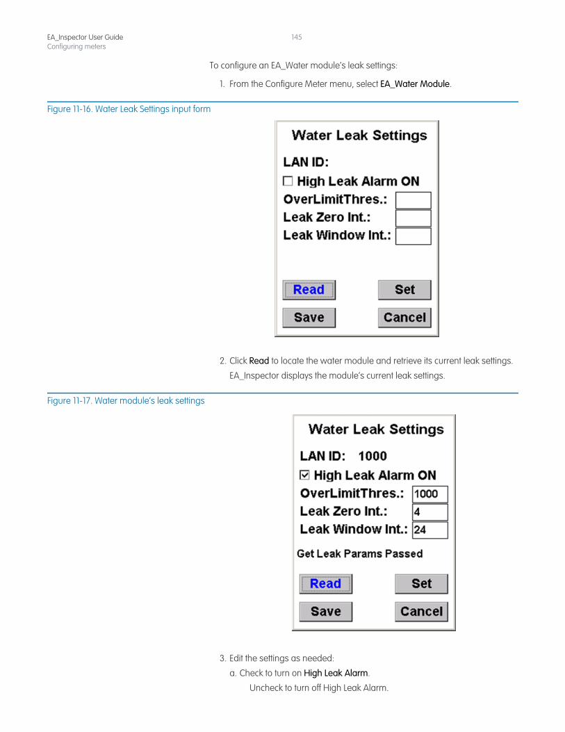
EA_Inspector User GuideConfiguring meters
145
To configure an EA_Water module’s leak settings:
1. From the Configure Meter menu, select EA_Water Module.
Figure 11-16. Water Leak Settings input form
2. Click Read to locate the water module and retrieve its current leak settings.
EA_Inspector displays the module’s current leak settings.
Figure 11-17. Water module’s leak settings
3. Edit the settings as needed:
a. Check to turn on High Leak Alarm.
Uncheck to turn off High Leak Alarm.
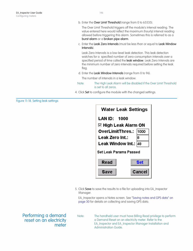
EA_Inspector User GuideConfiguring meters
146
b. Enter the Over Limit Threshold (range from 0 to 65535).
The Over Limit Threshold triggers off the module’s interval reading. The value entered here would reflect the maximum (hourly) interval reading allowed before triggering this alarm. Sometimes this is referred to as a burst alarm or a broken pipe alarm.
c. Enter the Leak Zero Intervals (must be less than or equal to Leak Window Intervals).
Leak Zero Intervals is a low-level leak detection. This leak detection watches for a specified number of zero-consumption intervals over a specified period of time called the leak window. Leak Zero Intervals are the minimum number of zero intervals required before setting the leak flag.
d. Enter the Leak Window Intervals (range from 0 to 96).
The number of intervals in a leak window.
Note: The High Leak Alarm will be disabled if the Over Limit Threshold is set to all zeros.
4. Click Set to configure the module with the changed settings.
Figure 11-18. Setting leak settings
5. Click Save to save the results to a file for uploading into EA_Inspector Manager.
EA_Inspector opens a Notes screen. See “Saving notes and GPS data” on page 30 for details on collecting and saving GPS data.
Performing a demandreset on an electricity
meter
Note: The handheld user must have Billing Read privilege to perform a Demand Reset on an electricity meter. Refer to the EA_Inspector and EA_Inspector Manager Installation and Administration Guide.
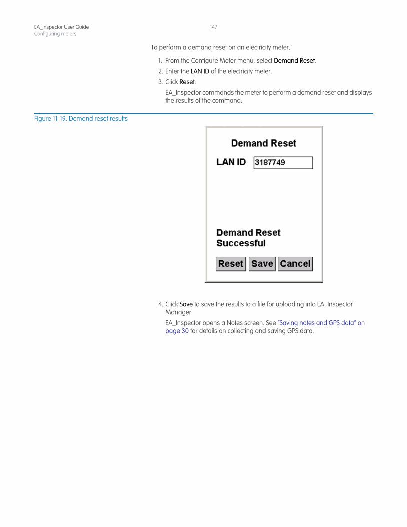
EA_Inspector User GuideConfiguring meters
147
To perform a demand reset on an electricity meter:
1. From the Configure Meter menu, select Demand Reset.
2. Enter the LAN ID of the electricity meter.
3. Click Reset.
EA_Inspector commands the meter to perform a demand reset and displays the results of the command.
Figure 11-19. Demand reset results
4. Click Save to save the results to a file for uploading into EA_Inspector Manager.
EA_Inspector opens a Notes screen. See “Saving notes and GPS data” on page 30 for details on collecting and saving GPS data.

EA_Inspector User GuideConfiguring meters
148
12 MANAGING HOME AREA NETWORK DEVICES
Certain REX and REX2 meters may be home area network enabled using a ZigBee network interface card (ZigBee NIC). The meter communicates to the ZigBee NIC relaying information such as consumption. The ZigBee NIC uses the HAN radio to communicate with a variety of home area devices such as in home displays, programmable thermostats, etc.
EA_Inspector allows you to perform the following commands on a ZigBee NIC:
• View Devices
• HAN NIC Info
Note: Meters that support ZigBee NIC are REX2 meters with firmware versions 2.x and higher.
Within the HAN menu items, once a user enters a Serial Number or LAN ID, that number or LAN ID will be saved and reshown on each HAN screen. If the user exits the HAN menu below and returns to the main menu, the Serial Number or LAN ID will be reset to blank.
HAN device-related screens show the device numbers as the number returned from the ZigBee NIC (in the range of 0 to 7).
EA_Inspector also allows you to perform the following commands on a 900 MHz HAN device:
• Commission • Ping • Configure • Decommission
Note: You must have Program 900 MHz HAN privileges to access the Configure command.
EA_Inspector User Guide
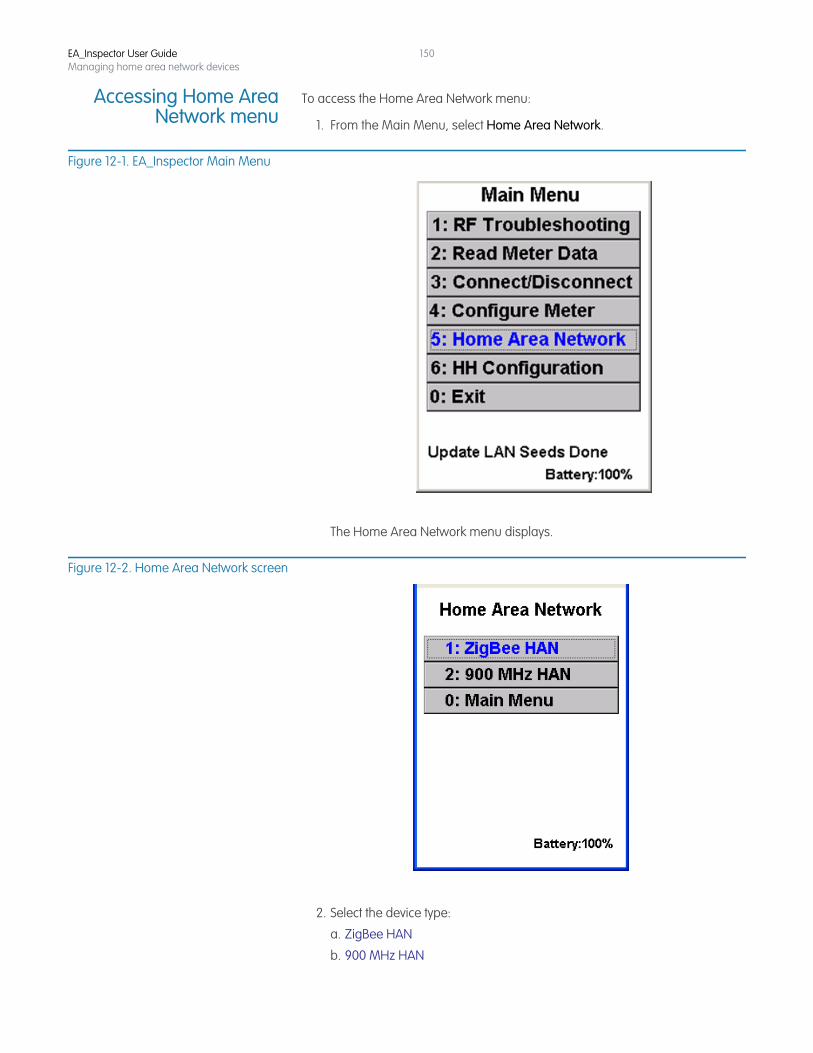
EA_Inspector User GuideManaging home area network devices
150
Accessing Home AreaNetwork menu
To access the Home Area Network menu:
1. From the Main Menu, select Home Area Network.
Figure 12-1. EA_Inspector Main Menu
The Home Area Network menu displays.
Figure 12-2. Home Area Network screen
2. Select the device type:
a. ZigBee HAN
b. 900 MHz HAN
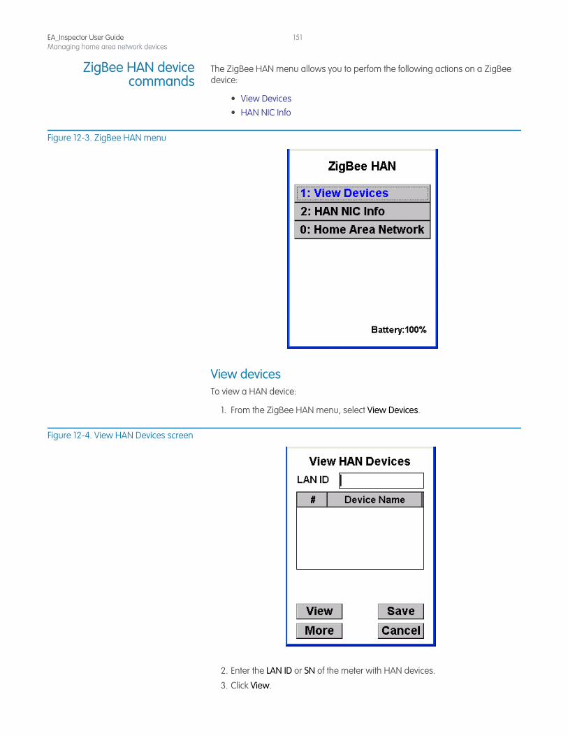
EA_Inspector User GuideManaging home area network devices
151
ZigBee HAN devicecommands
The ZigBee HAN menu allows you to perfom the following actions on a ZigBee device:
• View Devices • HAN NIC Info
Figure 12-3. ZigBee HAN menu
View devicesTo view a HAN device:
1. From the ZigBee HAN menu, select View Devices.
Figure 12-4. View HAN Devices screen
2. Enter the LAN ID or SN of the meter with HAN devices.
3. Click View.
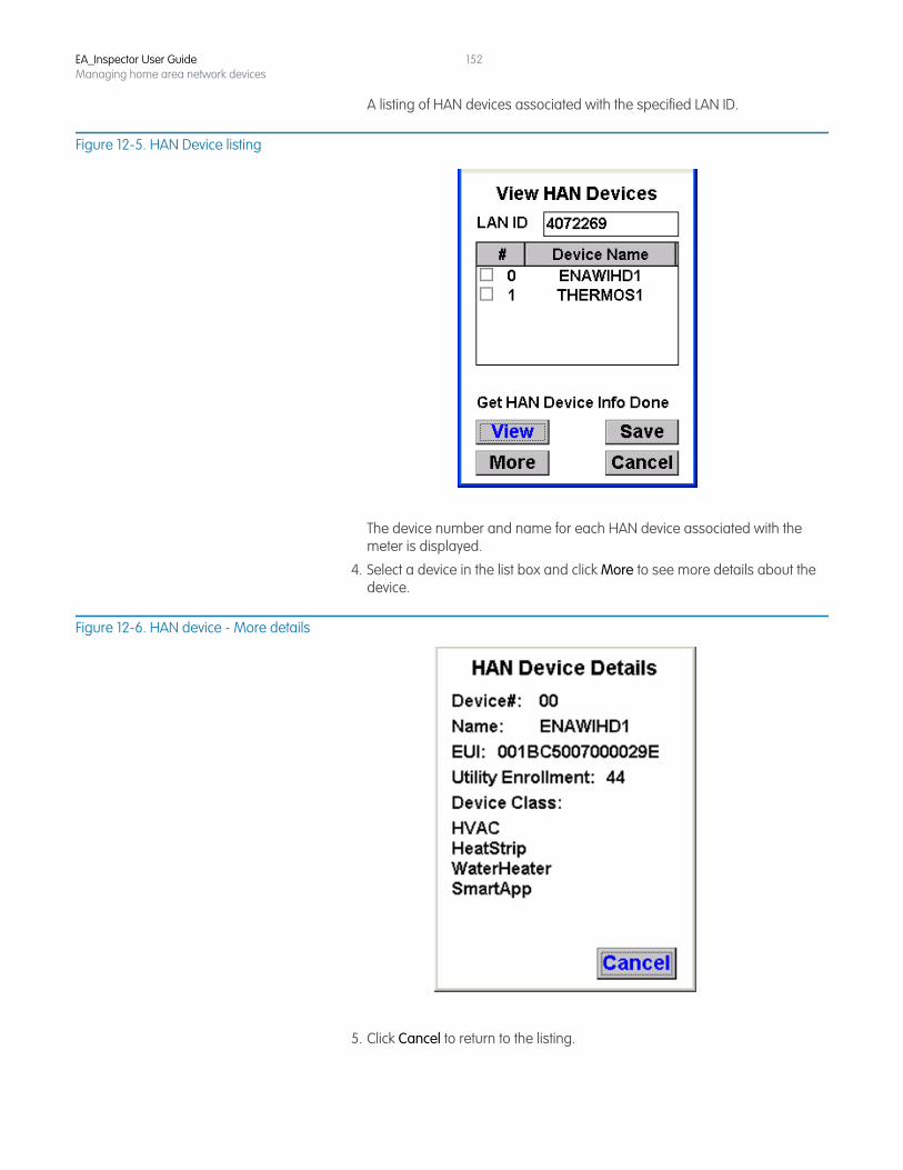
EA_Inspector User GuideManaging home area network devices
152
A listing of HAN devices associated with the specified LAN ID.
Figure 12-5. HAN Device listing
The device number and name for each HAN device associated with the meter is displayed.
4. Select a device in the list box and click More to see more details about the device.
Figure 12-6. HAN device - More details
5. Click Cancel to return to the listing.
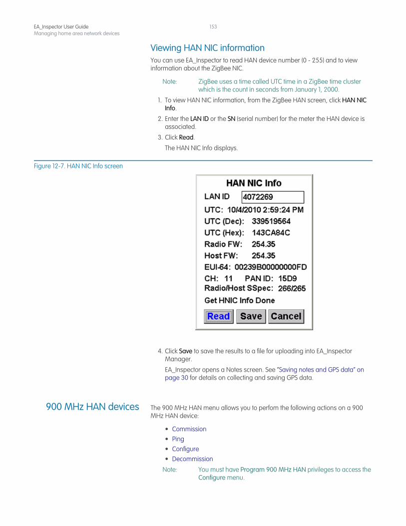
EA_Inspector User GuideManaging home area network devices
153
Viewing HAN NIC informationYou can use EA_Inspector to read HAN device number (0 - 255) and to view information about the ZigBee NIC.
Note: ZigBee uses a time called UTC time in a ZigBee time cluster which is the count in seconds from January 1, 2000.
1. To view HAN NIC information, from the ZigBee HAN screen, click HAN NIC Info.
2. Enter the LAN ID or the SN (serial number) for the meter the HAN device is associated.
3. Click Read.
The HAN NIC Info displays.
Figure 12-7. HAN NIC Info screen
4. Click Save to save the results to a file for uploading into EA_Inspector Manager.
EA_Inspector opens a Notes screen. See “Saving notes and GPS data” on page 30 for details on collecting and saving GPS data.
900 MHz HAN devices The 900 MHz HAN menu allows you to perfom the following actions on a 900 MHz HAN device:
• Commission • Ping • Configure • Decommission
Note: You must have Program 900 MHz HAN privileges to access the Configure menu.
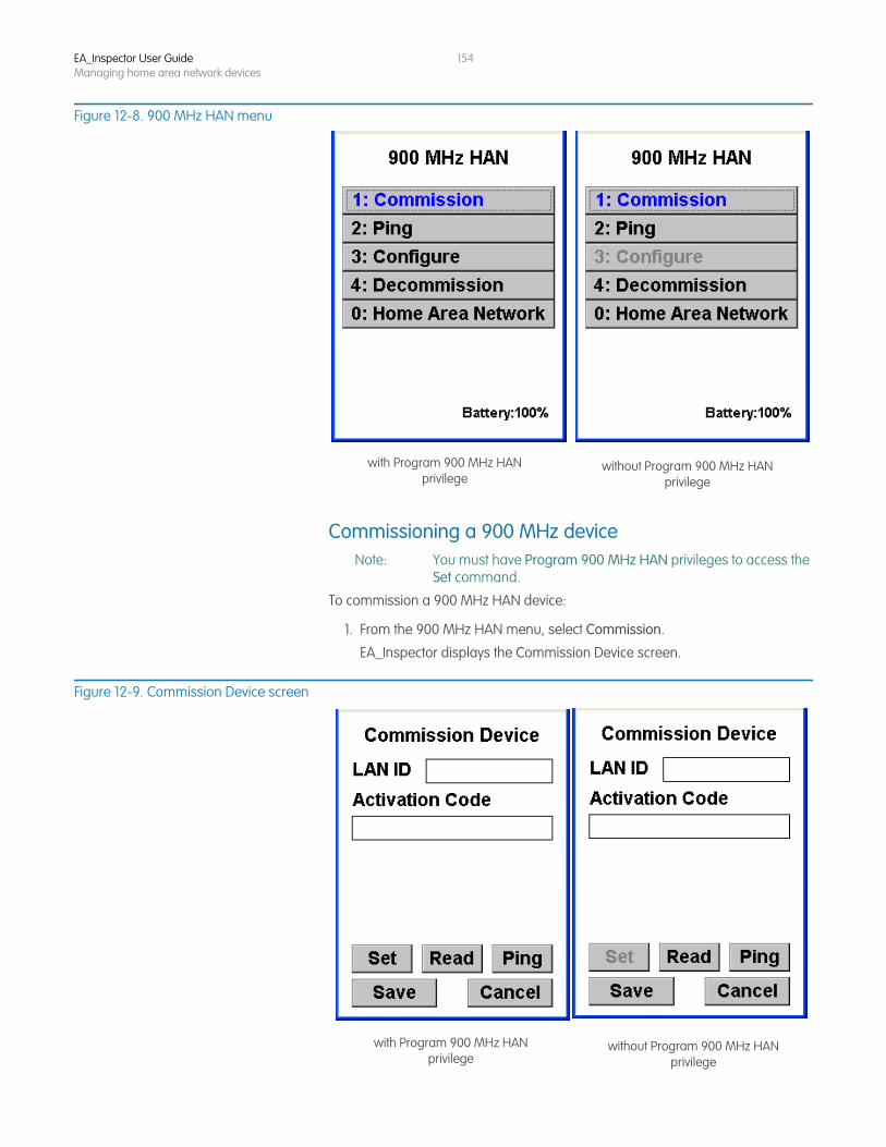
EA_Inspector User GuideManaging home area network devices
154
Figure 12-8. 900 MHz HAN menu
Commissioning a 900 MHz deviceNote: You must have Program 900 MHz HAN privileges to access the
Set command.
To commission a 900 MHz HAN device:
1. From the 900 MHz HAN menu, select Commission.
EA_Inspector displays the Commission Device screen.
Figure 12-9. Commission Device screen
with Program 900 MHz HANprivilege
without Program 900 MHz HANprivilege
with Program 900 MHz HANprivilege
without Program 900 MHz HANprivilege
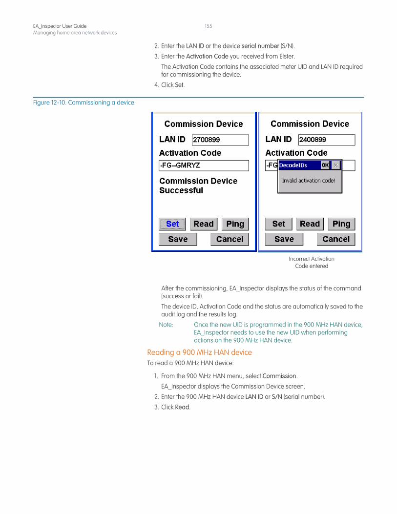
EA_Inspector User GuideManaging home area network devices
155
2. Enter the LAN ID or the device serial number (S/N).
3. Enter the Activation Code you received from Elster.
The Activation Code contains the associated meter UID and LAN ID required for commissioning the device.
4. Click Set.
Figure 12-10. Commissioning a device
After the commissioning, EA_Inspector displays the status of the command (success or fail).
The device ID, Activation Code and the status are automatically saved to the audit log and the results log.
Note: Once the new UID is programmed in the 900 MHz HAN device, EA_Inspector needs to use the new UID when performing actions on the 900 MHz HAN device.
Reading a 900 MHz HAN deviceTo read a 900 MHz HAN device:
1. From the 900 MHz HAN menu, select Commission.
EA_Inspector displays the Commission Device screen.
2. Enter the 900 MHz HAN device LAN ID or S/N (serial number).
3. Click Read.
Incorrect Activation Code entered
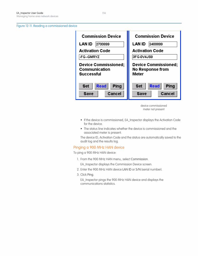
EA_Inspector User GuideManaging home area network devices
156
Figure 12-11. Reading a commissioned device
• If the device is commissioned, EA_Inspector displays the Activation Code for the device.
• The status line indicates whether the device is commissioned and the associated meter is present.
The device ID, Activation Code and the status are automatically saved to the audit log and the results log.
Pinging a 900 MHz HAN deviceTo ping a 900 MHz HAN device:
1. From the 900 MHz HAN menu, select Commission.
EA_Inspector displays the Commission Device screen.
2. Enter the 900 MHz HAN device LAN ID or S/N (serial number).
3. Click Ping.
EA_Inspector pings the 900 MHz HAN device and displays the communications statistics.
device commissionedmeter not present
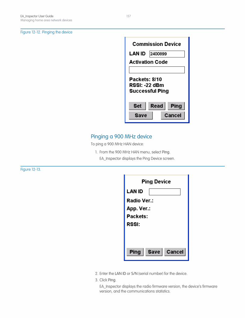
EA_Inspector User GuideManaging home area network devices
157
Figure 12-12. Pinging the device
Pinging a 900 MHz deviceTo ping a 900 MHz HAN device:
1. From the 900 MHz HAN menu, select Ping.
EA_Inspector displays the Ping Device screen.
Figure 12-13.
2. Enter the LAN ID or S/N (serial number) for the device.
3. Click Ping.
EA_Inspector displays the radio firmware version, the device’s firmware version, and the communications statistics.
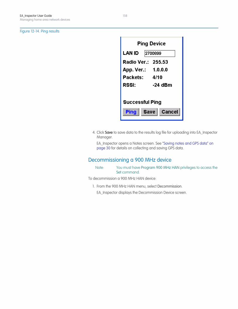
EA_Inspector User GuideManaging home area network devices
158
Figure 12-14. Ping results
4. Click Save to save data to the results log file for uploading into EA_Inspector Manager.
EA_Inspector opens a Notes screen. See “Saving notes and GPS data” on page 30 for details on collecting and saving GPS data.
Decommissioning a 900 MHz deviceNote: You must have Program 900 MHz HAN privileges to access the
Set command.
To decommission a 900 MHz HAN device:
1. From the 900 MHz HAN menu, select Decommission.
EA_Inspector displays the Decommission Device screen.
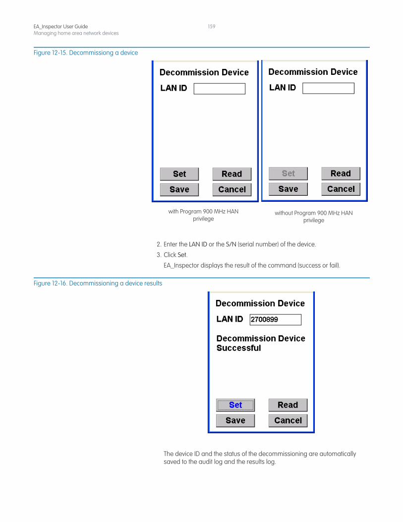
EA_Inspector User GuideManaging home area network devices
159
Figure 12-15. Decommissiong a device
2. Enter the LAN ID or the S/N (serial number) of the device.
3. Click Set.
EA_Inspector displays the result of the command (success or fail).
Figure 12-16. Decommissioning a device results
The device ID and the status of the decommissioning are automatically saved to the audit log and the results log.
with Program 900 MHz HANprivilege
without Program 900 MHz HANprivilege
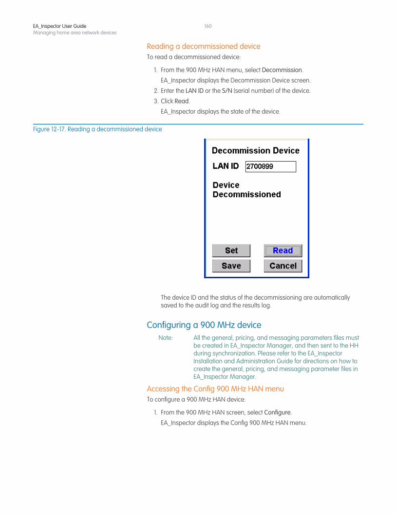
EA_Inspector User GuideManaging home area network devices
160
Reading a decommissioned deviceTo read a decommissioned device:
1. From the 900 MHz HAN menu, select Decommission.
EA_Inspector displays the Decommission Device screen.
2. Enter the LAN ID or the S/N (serial number) of the device.
3. Click Read.
EA_Inspector displays the state of the device.
Figure 12-17. Reading a decommissioned device
The device ID and the status of the decommissioning are automatically saved to the audit log and the results log.
Configuring a 900 MHz deviceNote: All the general, pricing, and messaging parameters files must
be created in EA_Inspector Manager, and then sent to the HH during synchronization. Please refer to the EA_Inspector Installation and Administration Guide for directions on how to create the general, pricing, and messaging parameter files in EA_Inspector Manager.
Accessing the Config 900 MHz HAN menuTo configure a 900 MHz HAN device:
1. From the 900 MHz HAN screen, select Configure.
EA_Inspector displays the Config 900 MHz HAN menu.
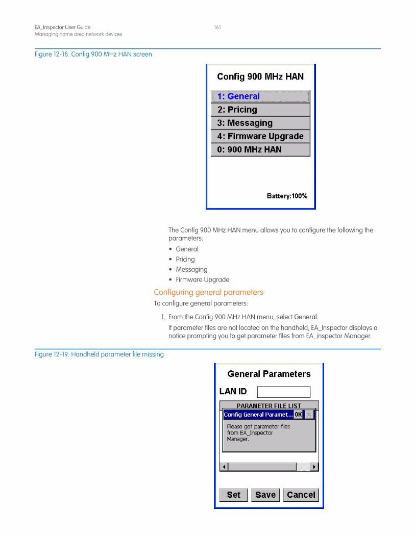
EA_Inspector User GuideManaging home area network devices
161
Figure 12-18. Config 900 MHz HAN screen
The Config 900 MHz HAN menu allows you to configure the following the parameters:
• General• Pricing• Messaging• Firmware Upgrade
Configuring general parametersTo configure general parameters:
1. From the Config 900 MHz HAN menu, select General.
If parameter files are not located on the handheld, EA_Inspector displays a notice prompting you to get parameter files from EA_inspector Manager.
Figure 12-19. Handheld parameter file missing
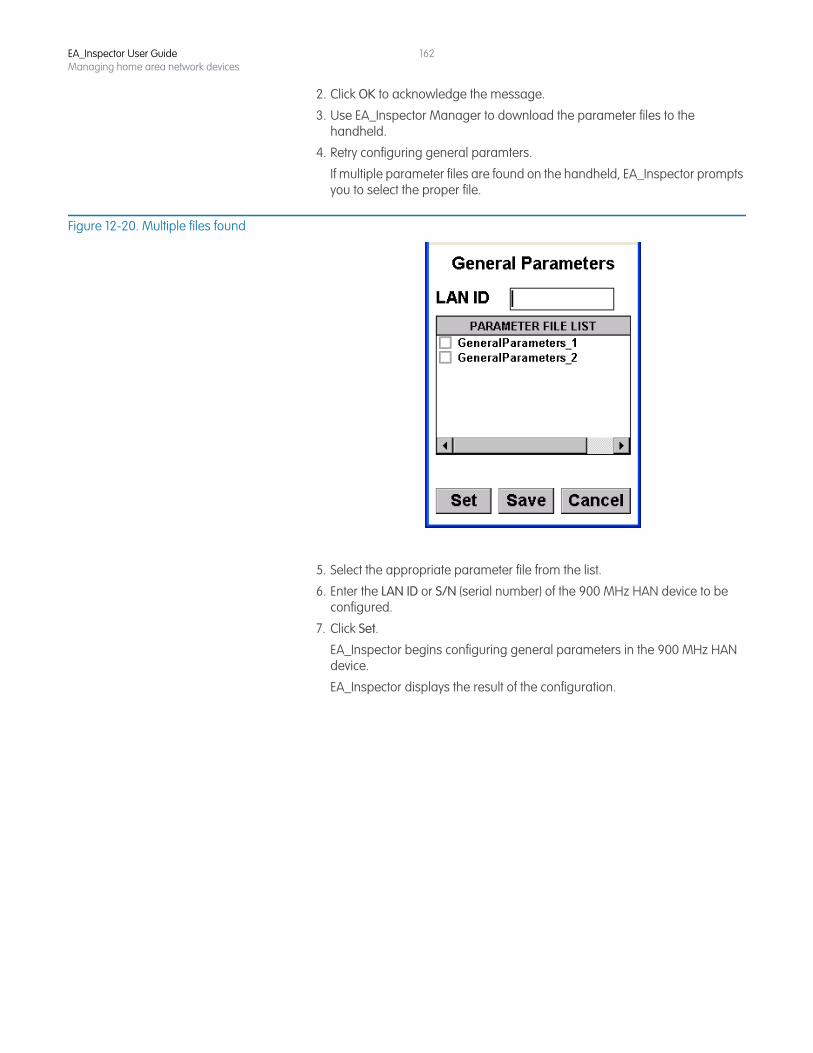
EA_Inspector User GuideManaging home area network devices
162
2. Click OK to acknowledge the message.
3. Use EA_Inspector Manager to download the parameter files to the handheld.
4. Retry configuring general paramters.
If multiple parameter files are found on the handheld, EA_Inspector prompts you to select the proper file.
Figure 12-20. Multiple files found
5. Select the appropriate parameter file from the list.
6. Enter the LAN ID or S/N (serial number) of the 900 MHz HAN device to be configured.
7. Click Set.
EA_Inspector begins configuring general parameters in the 900 MHz HAN device.
EA_Inspector displays the result of the configuration.
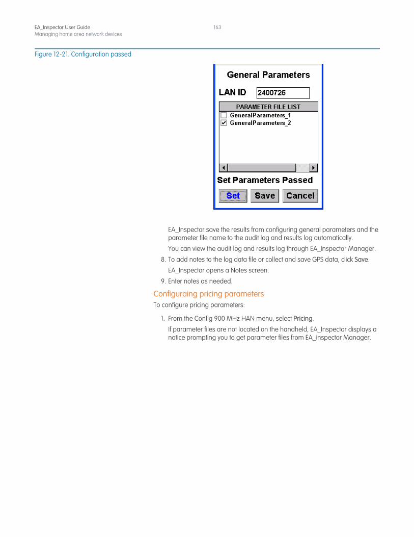
EA_Inspector User GuideManaging home area network devices
163
Figure 12-21. Configuration passed
EA_Inspector save the results from configuring general parameters and the parameter file name to the audit log and results log automatically.
You can view the audit log and results log through EA_Inspector Manager.
8. To add notes to the log data file or collect and save GPS data, click Save.
EA_Inspector opens a Notes screen.
9. Enter notes as needed.
Configuraing pricing parametersTo configure pricing parameters:
1. From the Config 900 MHz HAN menu, select Pricing.
If parameter files are not located on the handheld, EA_Inspector displays a notice prompting you to get parameter files from EA_inspector Manager.
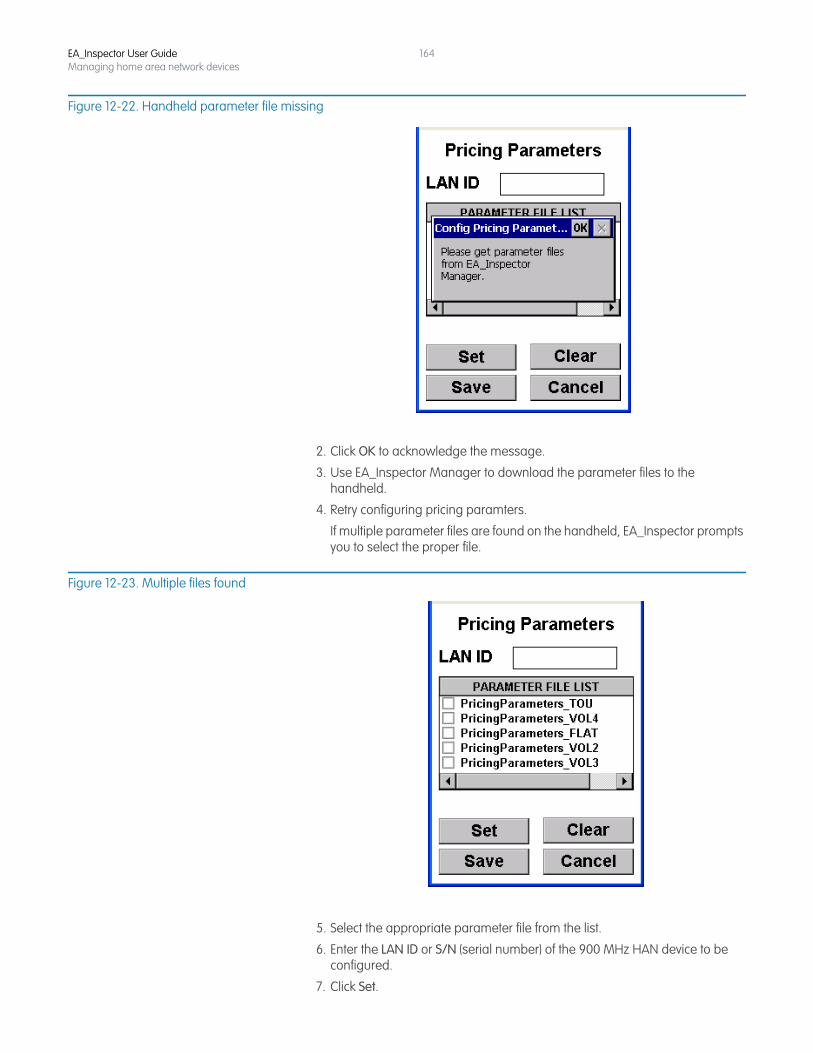
EA_Inspector User GuideManaging home area network devices
164
Figure 12-22. Handheld parameter file missing
2. Click OK to acknowledge the message.
3. Use EA_Inspector Manager to download the parameter files to the handheld.
4. Retry configuring pricing paramters.
If multiple parameter files are found on the handheld, EA_Inspector prompts you to select the proper file.
Figure 12-23. Multiple files found
5. Select the appropriate parameter file from the list.
6. Enter the LAN ID or S/N (serial number) of the 900 MHz HAN device to be configured.
7. Click Set.
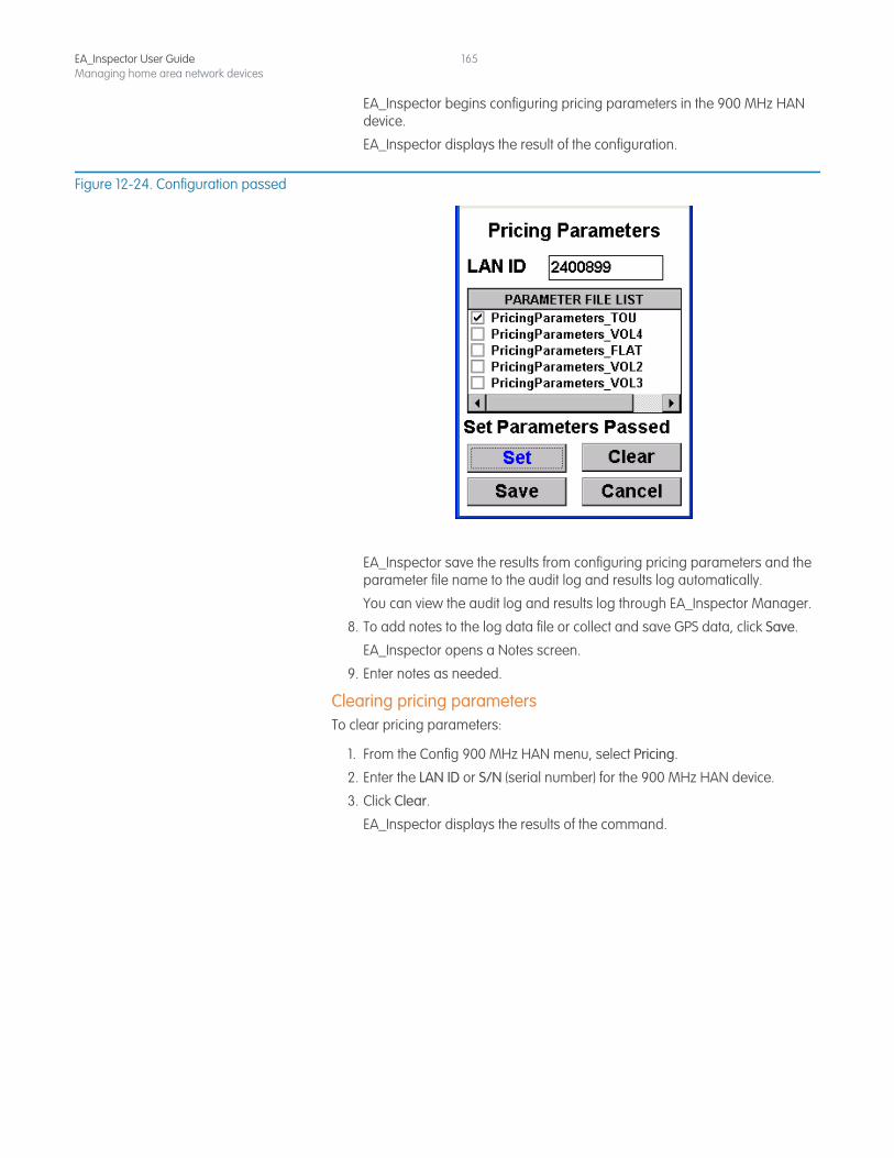
EA_Inspector User GuideManaging home area network devices
165
EA_Inspector begins configuring pricing parameters in the 900 MHz HAN device.
EA_Inspector displays the result of the configuration.
Figure 12-24. Configuration passed
EA_Inspector save the results from configuring pricing parameters and the parameter file name to the audit log and results log automatically.
You can view the audit log and results log through EA_Inspector Manager.
8. To add notes to the log data file or collect and save GPS data, click Save.
EA_Inspector opens a Notes screen.
9. Enter notes as needed.
Clearing pricing parametersTo clear pricing parameters:
1. From the Config 900 MHz HAN menu, select Pricing.
2. Enter the LAN ID or S/N (serial number) for the 900 MHz HAN device.
3. Click Clear.
EA_Inspector displays the results of the command.
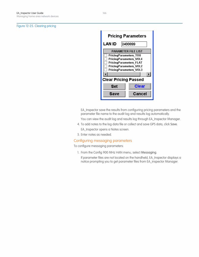
EA_Inspector User GuideManaging home area network devices
166
Figure 12-25. Clearing pricing
EA_Inspector save the results from configuring pricing parameters and the parameter file name to the audit log and results log automatically.
You can view the audit log and results log through EA_Inspector Manager.
4. To add notes to the log data file or collect and save GPS data, click Save.
EA_Inspector opens a Notes screen.
5. Enter notes as needed.
Configuring messaging parametersTo configure messaging parameters:
1. From the Config 900 MHz HAN menu, select Messaging.
If parameter files are not located on the handheld, EA_Inspector displays a notice prompting you to get parameter files from EA_inspector Manager.
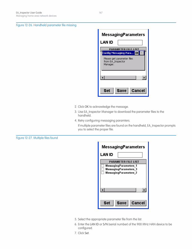
EA_Inspector User GuideManaging home area network devices
167
Figure 12-26. Handheld parameter file missing
2. Click OK to acknowledge the message.
3. Use EA_Inspector Manager to download the parameter files to the handheld.
4. Retry configuring messaging paramters.
If multiple parameter files are found on the handheld, EA_Inspector prompts you to select the proper file.
Figure 12-27. Multiple files found
5. Select the appropriate parameter file from the list.
6. Enter the LAN ID or S/N (serial number) of the 900 MHz HAN device to be configured.
7. Click Set.
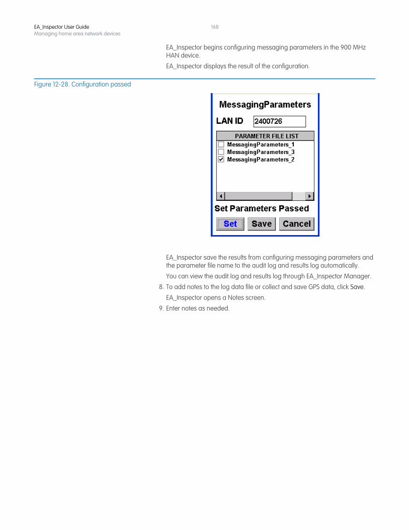
EA_Inspector User GuideManaging home area network devices
168
EA_Inspector begins configuring messaging parameters in the 900 MHz HAN device.
EA_Inspector displays the result of the configuration.
Figure 12-28. Configuration passed
EA_Inspector save the results from configuring messaging parameters and the parameter file name to the audit log and results log automatically.
You can view the audit log and results log through EA_Inspector Manager.
8. To add notes to the log data file or collect and save GPS data, click Save.
EA_Inspector opens a Notes screen.
9. Enter notes as needed.
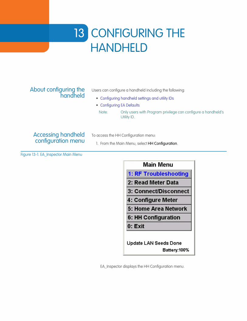
13 CONFIGURING THE HANDHELD
About configuring thehandheld
Users can configure a handheld including the following:
• Configuring handheld settings and utility IDs
• Configuring EA Defaults
Note: Only users with Program privilege can configure a handheld’s Utility ID.
Accessing handheldconfiguration menu
To access the HH Configuration menu:
1. From the Main Menu, select HH Configuration.
Figure 13-1. EA_Inspector Main Menu
EA_Inspector displays the HH Configuration menu.
EA_Inspector User Guide
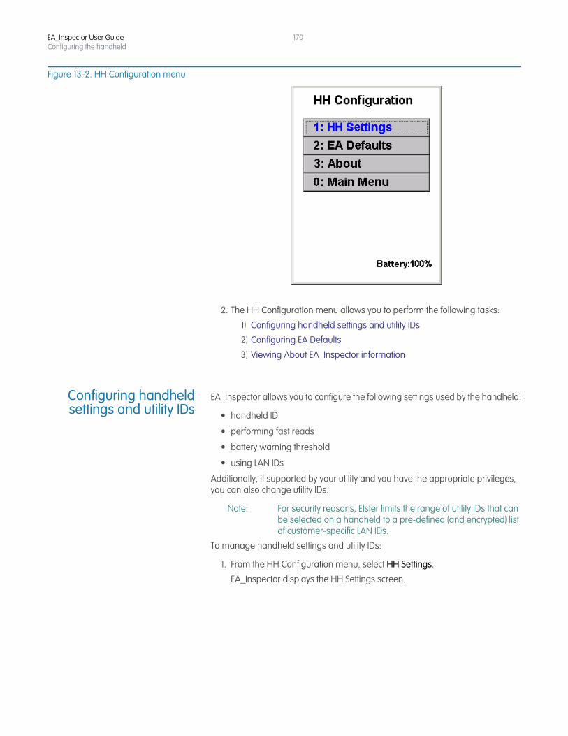
EA_Inspector User GuideConfiguring the handheld
170
Figure 13-2. HH Configuration menu
2. The HH Configuration menu allows you to perform the following tasks:
1) Configuring handheld settings and utility IDs
2) Configuring EA Defaults
3) Viewing About EA_Inspector information
Configuring handheldsettings and utility IDs
EA_Inspector allows you to configure the following settings used by the handheld:
• handheld ID
• performing fast reads
• battery warning threshold
• using LAN IDs
Additionally, if supported by your utility and you have the appropriate privileges, you can also change utility IDs.
Note: For security reasons, Elster limits the range of utility IDs that can be selected on a handheld to a pre-defined (and encrypted) list of customer-specific LAN IDs.
To manage handheld settings and utility IDs:
1. From the HH Configuration menu, select HH Settings.
EA_Inspector displays the HH Settings screen.
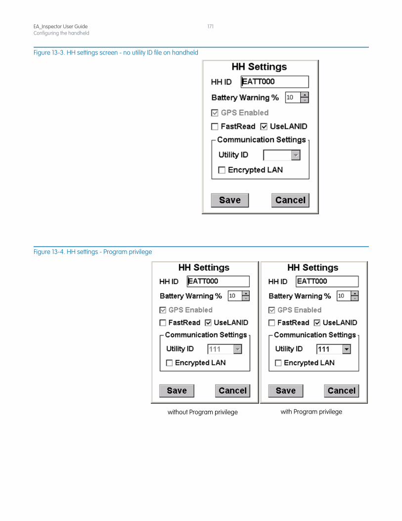
EA_Inspector User GuideConfiguring the handheld
171
Figure 13-3. HH settings screen - no utility ID file on handheld
Figure 13-4. HH settings - Program privilege
without Program privilege with Program privilege
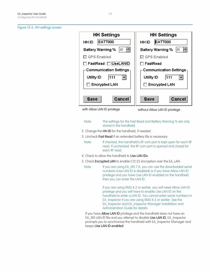
EA_Inspector User GuideConfiguring the handheld
172
Figure 13-5. HH settings screen
Note: The settings for the Fast Read and Battery Warning % are only stored in the handheld.
2. Change the HH ID for the handheld, if needed.
3. Uncheck Fast Read if an extended battery life is necessary.
Note: If checked, the handheld’s RF com port is kept open for each RF read. If unchecked, the RF com port is opened and closed for each RF read.
4. Check to allow the handheld to Use LAN IDs.
5. Check Encrypted LAN to enable C12.22 encryption over the EA_LAN.
Note: If you are using EA_MS 7.0, you can use the downloaded serial numbers (Use LAN ID is disabled) or if you have Allow LAN ID privilege and you have Use LAN ID enabled on the handheld then you can enter the LAN ID.
If you are using MAS 6.2 or earlier, you will need Allow LAN ID privilege and you will have to enable Use LAN ID on the handheld to enter a LAN ID. You cannot enter serial numbers in EA_Inspector if you are using MAS 6.2 or earlier. See the EA_Inspector and EA_Inspector Manager Installation and Administration Guide for details.
If you have Allow LAN ID privilege and the handheld does not have an EA_MS LAN ID file and you attempt to disable Use LAN ID, EA_Inspector prompts you to synchronize the handheld with EA_Inspector Manager and keeps Use LAN ID enabled.
with Allow LAN ID privilege without Allow LAN ID privilege
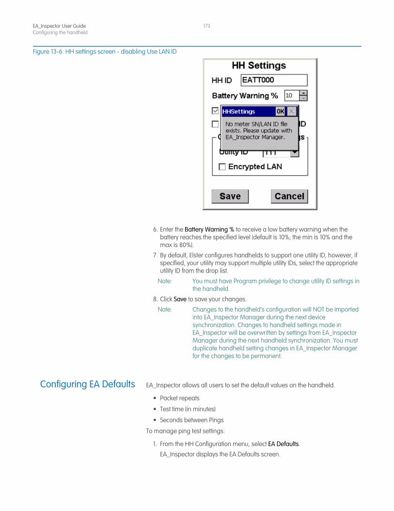
EA_Inspector User GuideConfiguring the handheld
173
Figure 13-6. HH settings screen - disabling Use LAN ID
6. Enter the Battery Warning % to receive a low battery warning when the battery reaches the specified level (default is 10%; the min is 10% and the max is 80%).
7. By default, Elster configures handhelds to support one utility ID, however, if specified, your utility may support multiple utility IDs, select the appropriate utility ID from the drop list.
Note: You must have Program privilege to change utility ID settings in the handheld.
8. Click Save to save your changes.
Note: Changes to the handheld’s configuration will NOT be imported into EA_Inspector Manager during the next device synchronization. Changes to handheld settings made in EA_Inspector will be overwritten by settings from EA_Inspector Manager during the next handheld synchronization. You must duplicate handheld setting changes in EA_Inspector Manager for the changes to be permanent.
Configuring EA Defaults EA_Inspector allows all users to set the default values on the handheld.
• Packet repeats
• Test time (in minutes)
• Seconds between Pings
To manage ping test settings:
1. From the HH Configuration menu, select EA Defaults.
EA_Inspector displays the EA Defaults screen.
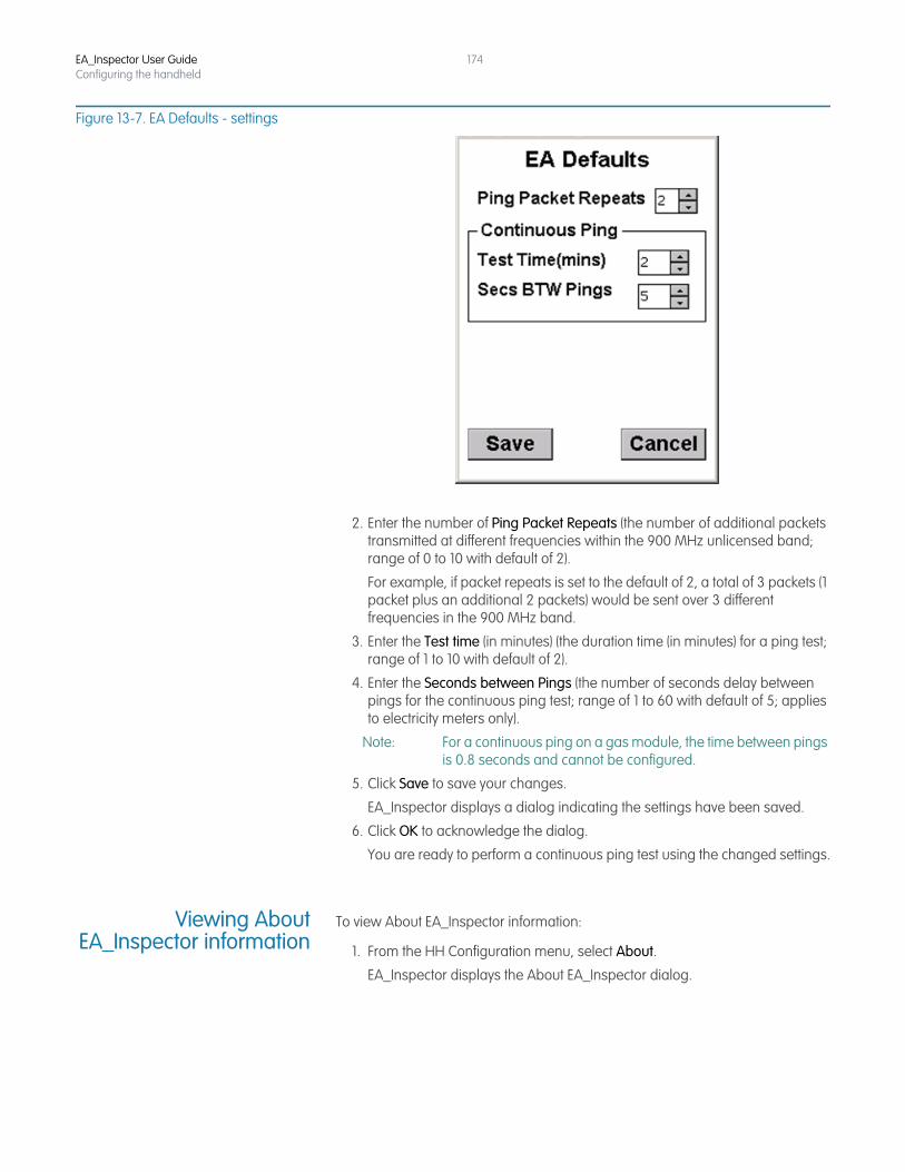
EA_Inspector User GuideConfiguring the handheld
174
Figure 13-7. EA Defaults - settings
2. Enter the number of Ping Packet Repeats (the number of additional packets transmitted at different frequencies within the 900 MHz unlicensed band; range of 0 to 10 with default of 2).
For example, if packet repeats is set to the default of 2, a total of 3 packets (1 packet plus an additional 2 packets) would be sent over 3 different frequencies in the 900 MHz band.
3. Enter the Test time (in minutes) (the duration time (in minutes) for a ping test; range of 1 to 10 with default of 2).
4. Enter the Seconds between Pings (the number of seconds delay between pings for the continuous ping test; range of 1 to 60 with default of 5; applies to electricity meters only).
Note: For a continuous ping on a gas module, the time between pings is 0.8 seconds and cannot be configured.
5. Click Save to save your changes.
EA_Inspector displays a dialog indicating the settings have been saved.
6. Click OK to acknowledge the dialog.
You are ready to perform a continuous ping test using the changed settings.
Viewing AboutEA_Inspector information
To view About EA_Inspector information:
1. From the HH Configuration menu, select About.
EA_Inspector displays the About EA_Inspector dialog.
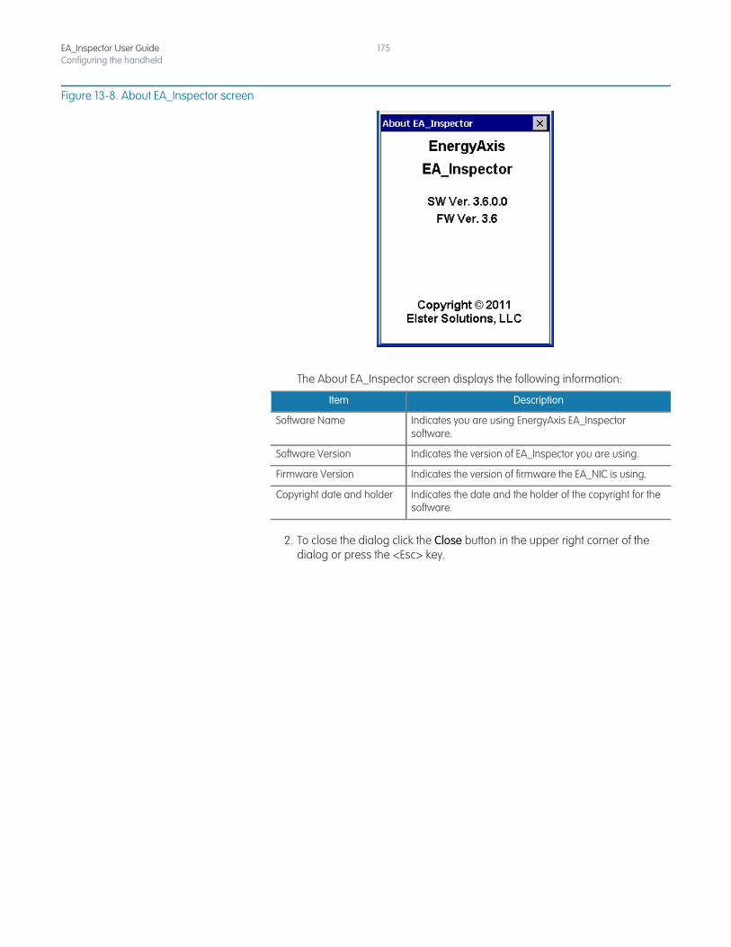
EA_Inspector User GuideConfiguring the handheld
175
Figure 13-8. About EA_Inspector screen
The About EA_Inspector screen displays the following information:
2. To close the dialog click the Close button in the upper right corner of the dialog or press the <Esc> key.
Item Description
Software Name Indicates you are using EnergyAxis EA_Inspector software.
Software Version Indicates the version of EA_Inspector you are using.
Firmware Version Indicates the version of firmware the EA_NIC is using.
Copyright date and holder Indicates the date and the holder of the copyright for the software.
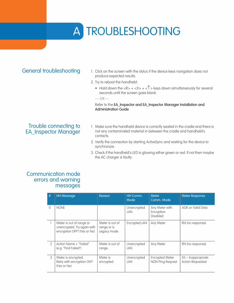
A TROUBLESHOOTING
General troubleshooting 1. Click on the screen with the stylus if the device keys navigation does not produce expected results.
2. Try to reboot the handheld:
• Hold down the <R> + <X> + <> keys down simultaneously for several seconds until the screen goes blank.
— OR —
Refer to the EA_Inspector and EA_Inspector Manager Installation and Administration Guide.
Trouble connecting toEA_Inspector Manager
1. Make sure the handheld device is correctly seated in the cradle and there is not any contaminated material in between the cradle and handheld's contacts.
2. Verify the connection by starting ActiveSync and waiting for the device to synchronize.
3. Check if the handheld's LED is glowing either green or red. If not then maybe the AC charger is faulty.
Communication modeerrors and warning
messages
# HH Message Reason HH Comm. Mode
Meter Comm. Mode
Meter Response
0 NONE Unencrypted LAN
Any Meter with Encryption Disabled
AOK or Valid Data
1 Meter is out of range or unencrypted. Try again with encryption OFF? (Yes or No)
Meter is out of range or is Legacy mode.
Encrypted LAN Any Meter RN (no response)
2 Action Name + “Failed” (e.g. “Find Failed”)
Meter is out of range.
Unencrypted LAN
Any Meter RN (no response)
3 Meter is encrypted. Retry with encryption ON? (Yes or No)
Meter is encrypted.
Unencrypted LAN
Encrypted MeterNON Ping Request
05 – Inappropriate Action Requested
EA_Inspector User Guide
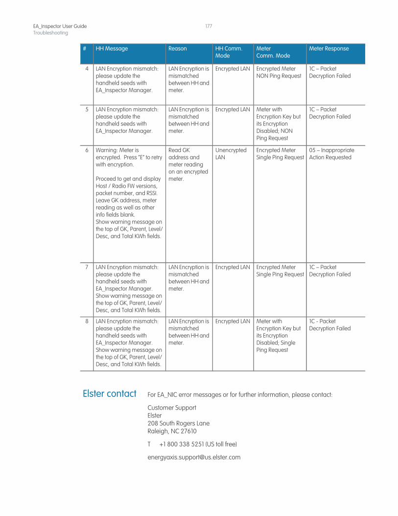
EA_Inspector User GuideTroubleshooting
177
Elster contact For EA_NIC error messages or for further information, please contact:
Customer SupportElster208 South Rogers LaneRaleigh, NC 27610
T +1 800 338 5251 (US toll free)
4 LAN Encryption mismatch: please update the handheld seeds with EA_Inspector Manager.
LAN Encryption is mismatched between HH and meter.
Encrypted LAN Encrypted MeterNON Ping Request
1C – Packet Decryption Failed
5 LAN Encryption mismatch: please update the handheld seeds with EA_Inspector Manager.
LAN Encryption is mismatched between HH and meter.
Encrypted LAN Meter with Encryption Key but its Encryption Disabled; NON Ping Request
1C – Packet Decryption Failed
6 Warning: Meter is encrypted. Press “E” to retry with encryption.
Proceed to get and display Host / Radio FW versions, packet number, and RSSI. Leave GK address, meter reading as well as other info fields blank.Show warning message on the top of GK, Parent, Level/Desc, and Total KWh fields.
Read GK address and meter reading on an encrypted meter.
Unencrypted LAN
Encrypted MeterSingle Ping Request
05 – Inappropriate Action Requested
7 LAN Encryption mismatch: please update the handheld seeds with EA_Inspector Manager.Show warning message on the top of GK, Parent, Level/ Desc, and Total KWh fields.
LAN Encryption is mismatched between HH and meter.
Encrypted LAN Encrypted MeterSingle Ping Request
1C – Packet Decryption Failed
8 LAN Encryption mismatch: please update the handheld seeds with EA_Inspector Manager. Show warning message on the top of GK, Parent, Level/ Desc, and Total KWh fields.
LAN Encryption is mismatched between HH and meter.
Encrypted LAN Meter with Encryption Key but its Encryption Disabled; Single Ping Request
1C - Packet Decryption Failed
# HH Message Reason HH Comm. Mode
Meter Comm. Mode
Meter Response

© 2011 by Elster. All rights reserved.No part of this software or documentation may be reproduced, transmitted, processed or recorded by anymeans or form, electronic, mechanical, photographic or otherwise, translated to another language, or bereleased to any third party without the express written consent of Elster.17.October.2011
Elster Solutions208 South Rogers LaneRaleigh NC 27610-2144T +1 800 338 5251 (US toll free)
www.elster.com