Embed Size (px)
Citation preview

RTU560 Remote Terminal Unit
IEC61850 Server
Contents: This manual gives an overview of the RTU560 Host Communication Interface with IEC61850 protocol.


ABB AG 1KGT 150 702 V002 1 iii
Revision
Document identity: 1KGT 150 702 V002 1
Revision: 0 Date: 06/2009 Base version
Revision: 1 Date: 01/2010 Corrections chapter 8 ‘Limits and recommendations’ Revision: 2 Date: 08/2010 Multicast information added
We reserve all rights in this document and in the information contained therein. Reproduction, use or disclosure to third parties without express authority is strictly forbidden. © Copyright 2010 ABB AG.


ABB AG 1KGT 150 702 V002 1 v
Contents
IEC61850 Server ............................................................................... i
Revision .......................................................................................... iii
Contents........................................................................................... v
Abbreviations ................................................................................ vii
Abbreviations ............................................................................... viii
Introduction .................................................................................... ix
Preface.......................................................................................................... ix References ................................................................................................... ix Conventions.................................................................................................. x
1 Physical Layer........................................................................ 1-1
2 Link Layer............................................................................... 2-1
2.1 General............................................................................................. 2-1 2.2 Client/server services..................................................................... 2-1
3 Application Layer................................................................... 3-1
4 Addressing............................................................................. 4-1
4.1 IEC61850 Object References ......................................................... 4-1 4.2 GOOSE Mulitcast Addressing ....................................................... 4-1
5 Monitoring Direction.............................................................. 5-1
5.1 SPI – Single Point Information....................................................... 5-1 5.2 DPI – Double Point Information..................................................... 5-3 5.3 STI – Step Position Information..................................................... 5-5 5.4 BSI – Bit String Information ........................................................... 5-6 5.5 ITI – Integrated Totals Information................................................ 5-8 5.6 DMI – Digital Measured Information.............................................. 5-9 5.7 AMI – Analog Measured Information .......................................... 5-11 5.8 MFI – Measured Float Information .............................................. 5-13
6 Controlling Direction ............................................................. 6-1
6.1 SCO – Single Command Output .................................................... 6-1
vi 1KGT 150 702 V002 1 ABB AG
6.2 DCO – Double Command Output...................................................6-2 6.3 RCO – Regulation Command Output ............................................6-3 6.4 ASO – Analog Setpoint Output ......................................................6-4 6.5 DSO – Digital Setpoint Output .......................................................6-6 6.6 BSO – Bit String Output .................................................................6-8
7 Internal Functions ..................................................................7-1
7.1 Time Synchronization .....................................................................7-1 7.2 General Interrogation......................................................................7-1 7.3 System Events.................................................................................7-1
7.3.1 System Events of RTU560...................................................7-1 7.3.2 System Events of GOOSE IEDs ..........................................7-2
7.4 System Commands .........................................................................7-3
8 Limits and recommendations ...............................................8-1
9 Conformance Statements......................................................9-1
9.1 Abstract Communication Service Interface (ACSI) .....................9-1 9.1.1 ACSI Basic Conformance Statement...................................9-1 9.1.2 ACSI Models Conformance Statement................................9-2 9.1.3 ACSI Service Conformance Statement ...............................9-3 9.1.4 Specific Communication Service Mapping (SCSM) ............9-4
9.2 Protocol Implementation Conformance Statement (PICS) .........9-5 9.2.1 Basic Profile Conformance ..................................................9-5 9.2.2 MMS Conformance ..............................................................9-5
9.3 Model Implementation Conformance Statement (MICS).............9-6 9.3.1 LN Group L: System logical nodes ......................................9-7 9.3.2 LN Group C: Logical nodes for control ................................9-8 9.3.3 LN Group G: Logical nodes for generic references .............9-9 9.3.4 Monitoring status information.............................................9-10 9.3.5 Measured information ........................................................9-13 9.3.6 Controllable status information ..........................................9-14 9.3.7 LN Group M: Logical nodes for metering and measurement9-17 9.3.8 LN Group P: Logical nodes for protection functions ..........9-19 9.3.9 LN Group R: Logical nodes for protection related functions9-23 9.3.10 LN Group S: Logical Nodes for sensors and monitoring ...9-24 9.3.11 LN Group X: Logical nodes for switchgear ........................9-25 9.3.12 LN Group Y: Logical nodes for power transformer ............9-26 9.3.13 LN Group Z: Logical Nodes for further power system equipment 9-27

ABB AG 1KGT 150 702 V002 1 vii
Abbreviations
ACSI Abstract Communication Service Interface
AMI Analog Measured value Input
ASO Analog Setpoint command Output
BCU Bus Connection Unit
BSI Bit String Input (8, 16 bit)
CMU Communication and Data Processing Unit
CS Control System
CSC Command Supervision Channel
CS-Command Clock Synch Command
DCE Data Communication Equipment
DCO Double Command Output
DMI Digital Measured value Input (8, 16 bit)
DPI Double Point Input
DSO Digital Setpoint command Output (8, 16 bit)
EPI Event of Protection equipment Input (1bit)
FC Functional Constraint
GCD General Configuration Data
GOOSE Generic Object Oriented Substation Event
HCI Host Communication Interface
IED Intelligent Electronic Device
IOC I/O Controller (Controller on I/O Board)
IOD Input Output Data
IOM I/O Bus Master (Function of SLC)
ITI Integrated Totals Input

viii 1KGT 150 702 V002 1 ABB AG
Abbreviations
MFI Analog Measured value Floating Input
MPU Main Processing Unit
NCC Network Control Center
PB Peripheral Bus
PBP Peripheral Bus Processor
PDP Process Data Processing
PLC Programmable Logic Control
PPP Point to Point Protocol
PSU Power Supply Unit
RCO Regulation step Command Output
RTC Real Time Clock
SBO Select before Operate
SCADA Supervision, Control and Data Acquisition
SCD Substation Configuration Description
SCI Sub-Device Communication Interface
SCL Substation Configuration description Language
SCO Single Command Output
SCSM Specific Communication Service Mapping
SEV System Event
SLC Serial Line Controller
SOC Strobe Output Channel
SPI Single Point Input
STI Step position Input (8 bit)
TSI Time Synch Input
TSO Time Synch Output

ABB AG 1KGT 150 702 V002 1 ix
Introduction
Preface
This document describes the functions of the host communication interface in RTU560 according to IEC61850.
References
[1] IEC61850-6:2004(E)
Communication networks and systems in substations
Part 6: Configuration description language for communication in electrical
substation related to IEDs
First edition 2004-03
[2] IEC61850-7-1:2003(E)
Communication networks and systems in substations
Part 7-1: Basic communication structure for substation and feeder equipment –
Principles and models
First edition 2003-07
[3] IEC61850-7-2:2003(E)
Communication networks and systems in substations
Part 7-2: Basic communication structure for substation and feeder equipment –
Abstract communication service interface (ACSI)
First edition 2003-05
[4] IEC61850-7-4:2003(E)
Communication networks and systems in substations
Part 7-4: Basic communication structure for substation and feeder equipment –
Compatible logical node classes and data classes
First edition 2003-05
[5] IEC61850-8-1:2004(E)
Communication networks and systems in substations
Part 8-1: Specific communication service mapping (SCSM) – Mappings to MMS
(ISO9506-1 and ISO9506-2) and to ISO/IEC 8802-3
First edition 2004-05
[6] 1KGT150451 V004 1
RTUtil560 User´s Guide
[7] 1KGT150589 V000 1
RTU560 Remote Terminal Unit
Function Description Release 8.0

x 1KGT 150 702 V002 1 ABB AG
Conventions
In this document function codes of data types according to IEC61850 are marked with angel brackets:
<Function code>
Italic fonts with the heading Parameter are references to configuration parameter in RTUtil560. The parameter is followed by definitions in round brackets where to find this parameter in RTUtil560.
Example: Parameter: Link address (RTU560 – Line parameter)
In this document references to elements of the standard will be printed bold and in brackets: [2, 7.4]
The tables in the next chapters include lists of functions, options and message types supported according to the protocol structure given in IEC60870-5 (EPA three layer model) for
the physical layer
the link layer
the application layer
This layered model is valid for the protocol [2].

ABB AG 1KGT 150 702 V002 1 1-1
1 Physical Layer
See documentation “Interfaces and Protocols” (1KGT150714)


ABB AG 1KGT 150 702 V002 1 2-1
2 Link Layer
2.1 General
The IEC61850 Server provides support for Server services as described in [5]. GOOSE/GSE Management Services and GSSE Services are supported as well.
Services like ‘Sampled Values’ described in IEC61850-9 are not supported.
2.2 Client/server services
The IEC61850 Server acts in IEC61850 station busses as a server.
Following services as described in [3] are supported:
IEC61850-7-2 model IEC61850-7-2 service HCI support Server GetServerDirectory X
Associate X Abort X
Association
Release X Logical Device GetLogicalDeviceDirectory X
GetLogicalNodeDirectory X Logical Node GetAllDataValues X GetDataValues X SetDataValues GetDataDirectory X
Data
GetDataDefinition X GetDataSetValues X SetDataSetValues CreateDataSet DeleteDataSet
Data Set
GetDataSetDirectory X GetDataValues Substitution SetDataValues SelectActiveSG SelectEditSG SetSGValues ConfirmEditSGValues GetSGValues
Setting Group Control Block
GetSGCBValues Report X GetBRCBValues X SetBRCBValues X GetURCBValues X
Report Control Block
SetURCBValues X GetLCBValues SetLCBValues GetLogStatusValues QueryLogByTime
LOG Control Block
QueryLogAfter

Link Layer RTU560 Host Communication Interface IEC61850
2-2 1KGT 150 702 V002 1 ABB AG
SendGOOSEMessage X GetGoReference X GetGOOSEElementNumber X GetGoCBValues
GOOSE
SetGoCBValues SendGSSEMessage GetGsReference GetGSSEElementNumber GetGsCBValues
GSSE
SetGsCBValues Select X SelectWithValue X Cancel X Operate X CommandTermination X
Control
TimeActivatedOperate GetFile SetFile DeleteFile
FILE transfer
GetFileAttributeValues
Table 2-1: Supported IEC61850-7-2 services

ABB AG 1KGT 150 702 V002 1 3-1
3 Application Layer
In IEC61850 information are grouped according to the process needs in logical nodes. Logical nodes consist of attributes of common data classes. Conversion of information is done on common data class basis. This gives the possibility to support also logical nodes probably defined in the future or for special process purposes.
Compatible logical nodes and data classes can be found in [4]. The supported logical nodes types are listed in the table below. Detailed information about the logical node could be found in chapter ‘9.3 Model Implementation Conformance Statement (MICS)’.
LN type Description LPHD Physical device information LLN0 Logical node zero CSWI Switch controller CILO Interlocking CRSV Reservation CALH Alarm handling GAPC Generic automatic process control GGIO Generic process I/O MMTR Metering MMXN Measurement MMXU Measurement PTOC Time over current protection PDIS Distance protection PDIF Differential protection PTOF Over frequency protection PTUF Under frequency protection PTOV Over voltage protection PTUV Under voltage protection PSDE Sensitive directional earth fault protection PTEF Transient earth fault protection PSCH Protection scheme PTRC Protection trip conditioning RBRF Breaker failure RREC Auto reclosing RSYN Synchronism-check or synchronizing SIMG Insulation medium supervision (gas) SIML Insulation medium supervision (liquid) XCBR Circuit breaker XSWI Circuit switch YLTC Tap changer YEFN Earth fault neutralizer (Petersen coil) ZAXN Auxiliary network
Table 3-1: Supported IEC61850-7-4 logical node types

Application Layer RTU560 Host Communication Interface IEC61850
3-2 1KGT 150 702 V002 1 ABB AG
The conversion of information is described in detail for every RTU560 data point type in the chapters below. As reference the following table summarizes the supported common data classes, their attributes and the possible mappings to RTU560 data point types.
Common Data Class
Attribute Name Default RTU560 data point type
Other RTU560 data point type
ACD dirGeneral DPI BSI ACD dirNeut DPI BSI ACD dirPhsA DPI BSI ACD dirPhsB DPI BSI ACD dirPhsC DPI BSI ACD general SPI DPI, SEV ACD neut SPI DPI, SEV ACD phsA SPI DPI, SEV ACD phsB SPI DPI, SEV ACD phsC SPI DPI, SEV ACT general SPI DPI, SEV ACT neut SPI DPI, SEV ACT phsA SPI DPI, SEV ACT phsB SPI DPI, SEV ACT phsC SPI DPI, SEV BCR actVal ITI - BCR frVal ITI - BSC Oper.ctlVal RCO - BSC valWTr.posVal STI - CMV cVal.mag.f MFI AMI DPC Oper.ctlVal DCO - DPC stVal DPI BSI DPS stVal DPI BSI INC Oper.ctlVal ASO BSO, DSO INC stVal AMI BSI, DMI, DPI, MFI INS stVal AMI BSI, DMI, DPI, MFI ISC Oper.ctlVal BSO - ISC valWTr.posVal STI - MV mag.f MFI AMI SPC Oper.ctlVal SCO - SPC stVal SPI DPI, SEV SPS stVal SPI DPI, SEV
Table 3-2: Mapping common data classes RTU560 data point types
The common data classes WYE and DEL (Logical nodes MMXU) are not stated in the table above because the data attributes of these classes are modeled with the common data class CMV.
The data attribute stSeld of the controllable common data classes are handled by the host interface itself. There is no need (or possibility) to convert this data attribute to a RTU560 data point.
ABB AG 1KGT 150 702 V002 1 4-1
4 Addressing
4.1 IEC61850 Object References
For addressing of IEC61850 object references are used. These references are a concatenation of the following names (see [2]):
LDName/LNName.DataName.DataAttribute[&FC]
Abbreviation Name Description LDName Logical device instance name Unique name of a logical device LNName Logical node instance name Concatenation of
LN Prefix LN name LN Instance number
DataName Name of common data class in logical node
DataAttribute Attribute name in common data class
FC Functional Constraint
References can not be modified with RTUtil560. The server data points with IEC61850 objects are defined in the Excel import file only. The GOOSE data points are synchronized from a SCD file to the Excel Import file of RTUtil560 without modifications.
Beside the IEC61850 object reference the address contains an ‘In use’ flag. This flag set in the Excel import file or RTUtil560 defines whether a data point is used in the IEC61850 host interface or not. If not set the data point is no part of the IEC61850 server data model.
The complete engineering process in RTUtil560 is described in [6].
4.2 GOOSE Mulitcast Addressing
For GOOSE communication within IEC61850 a multicast association model is used. In this model the publisher of a GOOSE message sends the information to a group of destinations simultaneously. This group is defined as multicast group.
In order to increase the overall performance of multicast message reception the filtering possibilities of the Media Access Control hardware is used in IEC61850 network. That means virtual MAC addresses are configured for each IED receiving or sending GOOSE messages. The virtual MAC address represents the multicast address or multicast group. The following MAC multicast addresses are recommended for an IEC61850 network.
Service Starting address (hexadecimal)
Ending address (hexadecimal)
GOOSE 01-0C-CD-01-00-00 01-0C-CD-01-01-FF

4-2 1KGT 150 702 V002 1 ABB AG
The RTU560 Ethernet interface (Intel 82557) is limited to maximum 12 different multicast addresses (own address and 11 others). This is a limit of the hardware and could not be extended.
For the RTU560 a maximum number of 12 multicast groups are possible. If more IEDs are communicating via GOOSE several IEDs must be merged in the same multicast group.
Please refer to IEC61850 standard for more information about the multicast association model.
ABB AG 1KGT 150 702 V002 1 5-1
5 Monitoring Direction
5.1 SPI – Single Point Information
Binary process information indicated by one bit:
Common Data Class
Attribute Name Functional Constraint
Conversion of Value Type
ACD general ST A ACD neut ST A ACD phsA ST A ACD phsB ST A ACD phsC ST A ACT general ST A ACT neut ST A ACT phsA ST A ACT phsB ST A ACT phsC ST A SPC stVal ST A
Supported Data Types
SPS stVal ST A
Additional None
Conversion of value (Type A)
RTU560 internal communication Protocol specific (Attribute value) Off FALSE On TRUE
Conversion of quality descriptors
RTU560 internal communication Protocol specific BL Blocked q.operatorBlocked == TRUE
q.validity == invalid q.detailQual.oldData == TRUE
SB Substituted q.source == substituted NT Not Topical q.detailQual.oldData == TRUE
q.validity == invalid IV Invalid q.validity == invalid
Monitoring Direction RTU560 Host Communication Interface IEC61850
5-2 1KGT 150 702 V002 1 ABB AG
Conversion of cause of transmission
RTU560 internal communication Protocol specific T Test q.test == TRUE P/N Positive/negative confirmation - Irrelevant - Cause Spontaneous - Requested - Interrogated -

RTU560 Host Communication Interface IEC61850 Monitoring Direction
ABB AG 1KGT 150 702 V002 1 5-3
5.2 DPI – Double Point Information
Binary process information indicated by two bits.
Common Data Class
Attribute Name Functional Constraint
Conversion of Value Type
ACD dirGeneral ST A
ACD dirNeut ST B
ACD dirPhsA ST B
ACD dirPhsB ST B
ACD dirPhsC ST B
DPC stVal ST C
DPS stVal ST C
ACD general ST D
ACD neut ST D
ACD phsA ST D
ACD phsB ST D
ACD phsC ST D
ACT general ST D
ACT neut ST D
ACT phsA ST D
ACT phsB ST D
ACT phsC ST D
SPC stVal ST D
Supported Data Types
SPS stVal ST D
Additional None
Conversion of value (Type A)
RTU560 internal communication Protocol specific (Attribute value) Intermediate Unknown Off Forward On Backward Indeterminate Both
Conversion of value (Type B)
RTU560 internal communication Protocol specific (Attribute value) Intermediate Unknown Off Forward On Backward Indeterminate -

Monitoring Direction RTU560 Host Communication Interface IEC61850
5-4 1KGT 150 702 V002 1 ABB AG
Conversion of value (Type C)
RTU560 internal communication Protocol specific (Attribute value) Intermediate intermediate-state Off Off On On Indeterminate bad-state
Conversion of value (Type D)
RTU560 internal communication Protocol specific (Attribute value) Intermediate Off Off Off On On Indeterminate Off
Conversion of quality descriptors
RTU560 internal communication Protocol specific BL Blocked q.operatorBlocked == TRUE
q.validity == invalid q.detailQual.oldData == TRUE
SB Substituted q.source == substituted NT Not Topical q.detailQual.oldData == TRUE
q.validity == invalid IV Invalid q.validity == invalid
Conversion of cause of transmission
RTU560 internal communication Protocol specific T Test q.test == TRUE P/N Positive/negative confirmation - Irrelevant - Cause Spontaneous - Requested - Interrogated -

RTU560 Host Communication Interface IEC61850 Monitoring Direction
ABB AG 1KGT 150 702 V002 1 5-5
5.3 STI – Step Position Information
Binary process information indicated by 8 bit.
Common Data Class
Attribute Name Functional Constraint
Conversion of Value Type
BSC valWTr.posVal ST A
Supported Data Types
ISC valWTr.posVal ST A
Additional None
Conversion of value (Type A)
RTU560 internal communication Protocol specific (Attribute value) Range min. -63 -63 ... ... Range max. +63 +63
Conversion of quality descriptors
RTU560 internal communication Protocol specific OV Overflow q.detailQual.overflow == TRUE
q.detailQual.outOfRange == TRUE q.validity == invalid
BL Blocked q.operatorBlocked == TRUE q.validity == invalid q.detailQual.oldData == TRUE
SB Substituted q.source == substituted NT Not Topical q.detailQual.oldData == TRUE
q.validity == invalid IV Invalid q.validity == invalid T Transient Bit -
Conversion of cause of transmission
RTU560 internal communication Protocol specific T Test q.test == TRUE P/N Positive/negative confirmation - Irrelevant - Cause Spontaneous - Requested - Interrogated -

Monitoring Direction RTU560 Host Communication Interface IEC61850
5-6 1KGT 150 702 V002 1 ABB AG
5.4 BSI – Bit String Information
Binary process information indicated by 8, 16 or 32 bit.
Common Data Class
Attribute Name Functional Constraint
Conversion of Value Type
ACD dirGeneral ST A
ACD dirNeut ST B
ACD dirPhsA ST B
ACD dirPhsB ST B
ACD dirPhsC ST B
DPC stVal ST C
DPS stVal ST C
INC stVal ST D
Supported Data Types
INS stVal ST D
Additional None
Conversion of value (Type A)
RTU560 internal communication Protocol specific (Attribute value) 0 unknown 1 forward 2 backward 3 both
Conversion of value (Type B)
RTU560 internal communication Protocol specific (Attribute value) 0 unknown 1 forward 2 backward
Conversion of value (Type C)
RTU560 internal communication Protocol specific (Attribute value) 0 intermediate-state 1 off 2 on 3 bad-state
RTU560 Host Communication Interface IEC61850 Monitoring Direction
ABB AG 1KGT 150 702 V002 1 5-7
Conversion of value (Type D)
RTU560 internal communication Protocol specific (Attribute value) Range min. 0 0 ... ...
BSI8: Bit mask of 8 bit; range ... 255
255
BSI16: Bit mask of 16 bit; range ... 65 535
65 535
Range max.
BSI32: Bit mask of 32 bit; range ... 4 294 967 295
4 294 967 295
Conversion of quality descriptors
RTU560 internal communication Protocol specific OV Overflow q.detailQual.overflow == TRUE
q.detailQual.outOfRange == TRUE q.validity == invalid
BL Blocked q.operatorBlocked == TRUE q.validity == invalid q.detailQual.oldData == TRUE
SB Substituted q.source == substituted NT Not Topical q.detailQual.oldData == TRUE
q.validity == invalid IV Invalid q.validity == invalid
Conversion of cause of transmission
RTU560 internal communication Protocol specific T Test q.test == TRUE P/N Positive/negative confirmation - Irrelevant - Cause Spontaneous - Requested - Interrogated -

Monitoring Direction RTU560 Host Communication Interface IEC61850
5-8 1KGT 150 702 V002 1 ABB AG
5.5 ITI – Integrated Totals Information
Binary process information indicated by 32 bit as a counted value.
Common Data Class
Attribute Name Functional Constraint
Conversion of Value Type
BCR actVal ST A
Supported Data Types
BCR frVal ST A
Additional None
Conversion of value (Type A)
RTU560 internal communication Protocol specific (Attribute value) Range min. -2147483648 -2147483648 ... ... ... Range max. +2147483647 +2147483647
Conversion of quality descriptors
RTU560 internal communication Protocol specific SEQ Sequence number - CY Carry q.detailQual.overflow == TRUE CA Adjusted - IV Invalid q.validity == invalid
Conversion of cause of transmission
RTU560 internal communication Protocol specific T Test q.test == TRUE P/N Positive/negative confirmation - Irrelevant - Cause Spontaneous - Requested - Interrogated -

RTU560 Host Communication Interface IEC61850 Monitoring Direction
ABB AG 1KGT 150 702 V002 1 5-9
5.6 DMI – Digital Measured Information
Binary process information indicated by integer values, used as a measured value from digital inputs.
Common Data Class
Attribute Name Functional Constraint
Conversion of Value Type
INC stVal ST A
Supported Data Types
INS stVal ST A
Additional Maximum Value Maximum Value in the external protocol to be converted to +100 % on RTU560 internal communication Parameter: Maximum Value (DMI – Protocol Address and Parameter) [Range: - 2147483648 .. 2147483647]
Minimum Value Minimum Value in the external protocol to be converted to -100 % on RTU560 internal communication. Parameter: Minimum Value (DMI- Protocol Address and Parameter) [Range: -2147483648 .. 2147483647]
Conversion of value (Type A)
RTU560 internal communication Protocol specific (Attribute value) Range min. -100% Parameter: Minimum Value ... ... Range max. +100% Parameter: Maximum Value

Monitoring Direction RTU560 Host Communication Interface IEC61850
5-10 1KGT 150 702 V002 1 ABB AG
Conversion of quality descriptors
RTU560 internal communication Protocol specific OV Overflow q.detailQual.overflow == TRUE
q.detailQual.outOfRange == TRUE q.validity == invalid
BL Blocked q.operatorBlocked == TRUE q.validity == invalid q.detailQual.oldData == TRUE
SB Substituted q.source == substituted NT Not Topical q.detailQual.oldData == TRUE
q.validity == invalid IV Invalid q.validity == invalid T Transient Bit valWTr.transInd
Conversion of cause of transmission
RTU560 internal communication Protocol specific T Test q.test == TRUE P/N Positive/negative confirmation - Irrelevant - Cause Spontaneous - Requested - Interrogated -
Measured Value,External Protocol
2047(Max. Value)
Value on internalcommunication
Example:Maximum Value = 2047Minimum Value = -2048
Scaling of Measurands, Host Communication Interface
- 100 % + 100 %
+ Range
- Range
- 2048(Min. Value)

RTU560 Host Communication Interface IEC61850 Monitoring Direction
ABB AG 1KGT 150 702 V002 1 5-11
5.7 AMI – Analog Measured Information
Analog process information indicated by integer or floating point values, used as a measured value from analog inputs.
Common Data Class
Attribute Name Functional Constraint
Conversion of Value Type
CMV cVal.mag.f MX A
INC stVal ST A
INS stVal ST A
Supported Data Types
MV mag.f MX A
Additional Maximum Value Maximum Value in the external protocol to be converted to +100 % on RTU560 internal communication Parameter: Maximum Value (AMI – Protocol Address and Parameter) [Range: - 2147483648 .. 2147483647]
Minimum Value Minimum Value in the external protocol to be converted to -100 % on RTU560 internal communication. Parameter: Minimum Value (AMI- Protocol Address and Parameter) [Range: -2147483648 .. 2147483647]
Conversion of value (Type A)
RTU560 internal communication Protocol specific (Attribute value) Range min. -100% Parameter: Minimum Value ... ... Range max. +100% Parameter: Maximum Value

Monitoring Direction RTU560 Host Communication Interface IEC61850
5-12 1KGT 150 702 V002 1 ABB AG
Conversion of quality descriptors
RTU560 internal communication Protocol specific OV Overflow q.detailQual.overflow == TRUE
q.detailQual.outOfRange == TRUE q.validity == invalid
BL Blocked q.operatorBlocked == TRUE q.validity == invalid q.detailQual.oldData == TRUE
SB Substituted q.source == substituted NT Not Topical q.detailQual.oldData == TRUE
q.validity == invalid IV Invalid q.validity == invalid T Transient Bit valWTr.transInd
Conversion of cause of transmission
RTU560 internal communication Protocol specific T Test q.test == TRUE P/N Positive/negative confirmation - Irrelevant - Cause Spontaneous - Requested - Interrogated -
Measured Value,External Protocol
2047(Max. Value)
Value on internalcommunication
Example:Maximum Value = 2047Minimum Value = -2048
Scaling of Measurands, Host Communication Interface
- 100 % + 100 %
+ Range
- Range
- 2048(Min. Value)

RTU560 Host Communication Interface IEC61850 Monitoring Direction
ABB AG 1KGT 150 702 V002 1 5-13
5.8 MFI – Measured Float Information
Analog process information indicated by 32 bit used as measured value from analog inputs in float format.
Common Data Class
Attribute Name Functional Constraint
Conversion of Value Type
CMV cVal.mag.f MX B
INC stVal ST A
INS stVal ST A
Supported Data Types
MV mag.f MX B
Additional None
Conversion of value (Type A)
RTU560 internal communication Protocol specific (Attribute value) Range min. -3.41038 (*) -2147483648 ... Range max. + 3.41038 (*) +2147483647
(*) Floating point value is truncated in the conversion
Conversion of value (Type B)
RTU560 internal communication Protocol specific (Attribute value) Range min. -3.41038 -3.41038 ... Range max. + 3.41038 + 3.41038
Conversion of quality descriptors
RTU560 internal communication Protocol specific OV Overflow q.detailQual.overflow == TRUE
q.detailQual.outOfRange == TRUE q.validity == invalid
BL Blocked q.operatorBlocked == TRUE q.validity == invalid q.detailQual.oldData == TRUE
SB Substituted q.source == substituted NT Not Topical q.detailQual.oldData == TRUE
q.validity == invalid IV Invalid q.validity == invalid

Monitoring Direction RTU560 Host Communication Interface IEC61850
5-14 1KGT 150 702 V002 1 ABB AG
Conversion of cause of transmission
RTU560 internal communication Protocol specific T Test q.test == TRUE P/N Positive/negative confirmation - Irrelevant - Cause Spontaneous - Requested - Interrogated -

ABB AG 1KGT 150 702 V002 1 6-1
6 Controlling Direction
6.1 SCO – Single Command Output
Binary process command (one bit)
Common Data Class
Attribute Name Functional Constraint
Conversion of Value Type
Supported Data Types
SPC Oper.ctlVal CO A
Command Authority
None
Additional Signal Support select before operate Parameter: Select before operate (SCO – Protocol Address and Parameter)
Conversion of value (Type A)
RTU560 internal communication Protocol specific (Attribute value) off FALSE on TRUE
Conversion of quality descriptors
RTU560 internal communication Protocol specific SE Select / Execute ACSI control service: SBO/SBOw request /
ACSI control service: Operate request
Conversion of cause of transmission
RTU560 internal communication Protocol specific T Test ACSI control service:
Test parameter P/N Positive/negative confirmation ACSI control service:
response +/- Cause Activation ACSI control service:
Select/Operate request Activation Confirmation ACSI control service:
Select/Operate response Deactivation ACSI control service:
Cancel request Deactivation Confirmation ACSI control service:
Cancel response Activation Termination Report with termination information

Controlling Direction RTU560 Host Communication Interface IEC61850
6-2 1KGT 150 702 V002 1 ABB AG
6.2 DCO – Double Command Output
Binary process command (two bits)
Common Data Class
Attribute Name Functional Constraint
Conversion of Value Type
Supported Data Types
DPC Oper.ctlVal CO A
Command Authority
None
Additional Signal Support select before operate Parameter: Select before operate (DCO – Protocol Address and Parameter)
Conversion of value (Type A)
RTU560 internal communication Protocol specific (Attribute value) Off FALSE On TRUE
Conversion of quality descriptors
RTU560 internal communication Protocol specific SE Select / Execute ACSI control service: SBO/SBOw request /
ACSI control service: Operate request
Conversion of cause of transmission
RTU560 internal communication Protocol specific T Test ACSI control service:
Test parameter P/N Positive/negative confirmation ACSI control service:
response +/- Cause Activation ACSI control service:
Select/Operate request Activation Confirmation ACSI control service:
Select/Operate response Deactivation ACSI control service:
Cancel request Deactivation Confirmation ACSI control service:
Cancel response Activation Termination Report with termination information
RTU560 Host Communication Interface IEC61850 Controlling Direction
ABB AG 1KGT 150 702 V002 1 6-3
6.3 RCO – Regulation Command Output
Regulation process command (two bits)
Common Data Class
Attribute Name Functional Constraint
Conversion of Value Type
Supported Data Types
BSC Oper.ctlVal CO A
Command Authority
None
Additional Signal Support select before operate Parameter: Select before operate (RCO – Protocol Address and Parameter)
Conversion of value (Type A)
RTU560 internal communication Protocol specific (Attribute value) Lower lower Higher higher
Conversion of quality descriptors
RTU560 internal communication Protocol specific SE Select / Execute ACSI control service: SBO/SBOw request /
ACSI control service: Operate request
Conversion of cause of transmission
RTU560 internal communication Protocol specific T Test ACSI control service:
Test parameter P/N Positive/negative confirmation ACSI control service:
response +/- Cause Activation ACSI control service:
Select/Operate request Activation Confirmation ACSI control service:
Select/Operate response Deactivation ACSI control service:
Cancel request Deactivation Confirmation ACSI control service:
Cancel response Activation Termination Report with termination information
Controlling Direction RTU560 Host Communication Interface IEC61850
6-4 1KGT 150 702 V002 1 ABB AG
6.4 ASO – Analog Setpoint Output
Analog process command (16 bit signed number)
Common Data Class
Attribute Name Functional Constraint
Conversion of Value Type
Supported Data Types
INC Oper.ctlVal CO A
Command Authority
None
Additional Signal Support select before operate Parameter: Select before operate (ASO – Protocol Address and Parameter)
Maximum Value Maximum Value in the external protocol to be converted to +100 % on RTU560 internal communication Parameter: Maximum Value (ASO – Protocol Address and Parameter) [Range: -32768 .. 32767]
Minimum Value Minimum Value in the external protocol to be converted to -100 % on RTU560 internal communication. Parameter: Minimum Value (ASO- Protocol Address and Parameter) [Range: -32768 .. 32767]
Conversion of value (Type A)
RTU560 internal communication Protocol specific (Attribute value) Range min. -100% Parameter: Minimum Value ... ... Range max. +100% Parameter: Maximum Value

RTU560 Host Communication Interface IEC61850 Controlling Direction
ABB AG 1KGT 150 702 V002 1 6-5
Setpoint Value,External Protocol
2047(Max. Value)
Value on internalcommunication
Example:Maximum Value = 2047Minimum Value = -2048
Scaling of Setpoints, Subdevice Communication Interface
- 100 % + 100 %
+ Range
- Range
- 2048(Min. Value)
Conversion of quality descriptors
RTU560 internal communication Protocol specific SE Select / Execute ACSI control service: SBO/SBOw request /
ACSI control service: Operate request
Conversion of cause of transmission
RTU560 internal communication Protocol specific T Test ACSI control service:
Test parameter P/N Positive/negative confirmation ACSI control service:
response +/- Cause Activation ACSI control service:
Select/Operate request Activation Confirmation ACSI control service:
Operate response Deactivation - Deactivation Confirmation - Activation Termination -

Controlling Direction RTU560 Host Communication Interface IEC61850
6-6 1KGT 150 702 V002 1 ABB AG
6.5 DSO – Digital Setpoint Output
Binary process command (8 or 16 bit signed number)
Common Data Class
Attribute Name Functional Constraint
Conversion of Value Type
Supported Data Types
INC Oper.ctlVal CO A
Command Authority
None
Additional Signal Support select before operate Parameter: Select before operate (DSO – Protocol Address and Parameter)
Maximum Value Maximum Value in the external protocol to be converted to +100 % on RTU560 internal communication Parameter: Maximum Value (DSO – Protocol Address and Parameter) [Range: -32768 .. 32767]
Minimum Value Minimum Value in the external protocol to be converted to -100 % on RTU560 internal communication. Parameter: Minimum Value (DSO- Protocol Address and Parameter) [Range: -32768 .. 32767]
Conversion of value (Type A)
RTU560 internal communication Protocol specific (Attribute value) Range min. -100% Parameter: Minimum Value ... ... Range max. +100% Parameter: Maximum Value

RTU560 Host Communication Interface IEC61850 Controlling Direction
ABB AG 1KGT 150 702 V002 1 6-7
Setpoint Value,External Protocol
2047(Max. Value)
Value on internalcommunication
Example:Maximum Value = 2047Minimum Value = -2048
Scaling of Setpoints, Subdevice Communication Interface
- 100 % + 100 %
+ Range
- Range
- 2048(Min. Value)
Conversion of quality descriptors
RTU560 internal communication Protocol specific SE Select / Execute ACSI control service: SBO/SBOw request /
ACSI control service: Operate request
Conversion of cause of transmission
RTU560 internal communication Protocol specific T Test ACSI control service:
Test parameter P/N Positive/negative confirmation ACSI control service:
response +/- Cause Activation ACSI control service:
Select/Operate request Activation Confirmation ACSI control service:
Operate response Deactivation - Deactivation Confirmation - Activation Termination -

Controlling Direction RTU560 Host Communication Interface IEC61850
6-8 1KGT 150 702 V002 1 ABB AG
6.6 BSO – Bit String Output
Binary process command (1, 2, 8, 16 bit unsigned number)
Common Data Class
Attribute Name Functional Constraint
Conversion of Value Type
INC Oper.ctlVal CO A
Supported Data Types
ISC Oper.ctlVal CO B
Command Authority
None
Additional None
Conversion of value (Type A)
RTU560 internal communication Protocol specific (Attribute value) Range min. 0 0 ... ... … 32767 32767 … … 32768 -32768 … … … Range max. 65535 -1
Protocol specific value range is mapped to BSO8 and BSO16 in 2´s complement format.
Conversion of value (Type A)
RTU560 internal communication Protocol specific (Attribute value) Range min. 0 0 ... ... … 63 63 … … 65471 -64 … … … Range max. 65535 -1
Protocol specific value range is mapped to BSO8 and BSO16 in 2´s complement format.
Conversion of quality descriptors
RTU560 internal communication Protocol specific SE Select / Execute ACSI control service: SBO/SBOw request /
ACSI control service: Operate request

RTU560 Host Communication Interface IEC61850 Controlling Direction
ABB AG 1KGT 150 702 V002 1 6-9
Conversion of cause of transmission
RTU560 internal communication Protocol specific T Test ACSI control service:
Test parameter P/N Positive/negative confirmation ACSI control service:
response +/- Cause Activation ACSI control service:
Select/Operate request Activation Confirmation ACSI control service:
Operate response Deactivation - Deactivation Confirmation - Activation Termination -


ABB AG 1KGT 150 702 V002 1 7-1
7 Internal Functions
7.1 Time Synchronization
Time synchronization of subordinated devices is done using SNTP time synchronization protocol. SNTP time synchronization protocol is a general function of RTU560 and must be configured with RTUtil560. The configuration of SNTP is described in document ‘Function Description’ (1KGT 150 582) of RTU560.
7.2 General Interrogation
The general interrogation to subordinated devices is part of the report control block handling defined in IEC61850. There is no specific general interrogation command existing.
7.3 System Events
7.3.1 System Events of RTU560
The host communication interface manages internal status messages of the RTU560. These status messages can be created from the HCI itself or other activities of the RTU560. The system events of other activities are sent via internal communication and are processed by the HCI.
The system events could be mapped to IEC61850 status data attributes of type BOOLEAN. See chapter ‘3 Application Layer’ for common data classes and attributes convertable to system events.
The following table shows the system events supported by the host communication interface IEC61850:

Internal Functions RTU560 Host Communication Interface IEC61850
7-2 1KGT 150 702 V002 1 ABB AG
Description of system event Shortcut At least one indication faulty #016 At least one analog value faulty #017 At least one digital value faulty #018 At least one pulse counter faulty #019 At least one command is faulty #020 At least one setpoint is faulty #021 At least one digital output is faulty #022 RTU is faulty #023 RTU is active #024 RTU is synchronized #025 External clock is inoperable #026 Local printer offline #027 At least one indication oscillating #028 System battery low (RTU560E only) #029 AC power supply failed (RTU560E only) #030 At least one DCE faulty #044 Device connected #045 At least one PLC function not running #046 At least one PLC function cycle time exceeded #047 RTU inoperable #048 RTU out of service #049 Power supply failure in CSR subrack #059 Command supervision circuit z disconnected or faulty, 1 ≤ z ≤ 32 #064 ... #095 SNTP client 1 is synchronized #096 SNTP client 2 is synchronized #097 Local control authority active #100 Host x Online, 1 ≤ x ≤ 8 #101 ... #108 Host interface x: At least one change of information lost, 1 ≤ x ≤ 8 #117 ... #124 Host interface x: At least one pulse counter lost, 1 ≤ x ≤ 8 #133 ... #140 CMU in rack 0, slot x is inoperable, 1 ≤ x ≤ 8, 10 #149 … #156 CMU in rack 1, slot x is inoperable, 1 ≤ x ≤ 8 #157 … #164 Device reachable on redundant line x, 1 ≤ x ≤ 4 #180 … #183 Device active on redundant line x, 1 ≤ x ≤ 4 #184 … #187 Device preferred on redundant line x, 1 ≤ x ≤ 4 #188 … #191 Network element x is operable, 1 ≤ x ≤ 32 #192 … #223 CMU in rack 0, slot x is active, 1 ≤ x ≤ 8 #224 … #231 CMU in rack 1, slot x is active, 1 ≤ x ≤ 8, 10 #232 … #239
7.3.2 System Events of GOOSE IEDs
The host communication interface manages internal status messages for every GOOSE IED that sends data to the HCI. These status messages are created from the host communication interface itself for every GOOSE IED.
The host communication interface supports the following system events for GOOSE IEDs:
Description of system event Shortcut Device active #024 Device inoperable #048
Internal Functions RTU560 Host Communication Interface IEC61850
ABB AG 1KGT 150 702 V002 1 7-3
Conversion of value
Description RTU560
internal Protocol specific
off Device not active Device active on Device active off All GOOSE data points valid Device inoperable on At least one GOOSE data point invalid
While initialization the value of system event ‘Device is active’ (#024) is set to ON. On a running system this system event doesn’t change anymore.
The system event ‘Device inoperable’ (#048) is set in dependency of the GOOSE data points received from the IED. If all data points are received and valid the system event is set to operable (state ‘off’). If at least one data point is not received or invalid the system event is set to inoperable (state ‘on’).
7.4 System Commands
System commands are not supported.


ABB AG 1KGT 150 702 V002 1 8-1
8 Limits and recommendations
Following table specifies the system limits of IEC61850 Server in RTU560:
Description Limit
Maximum number of IEC61850 Server per RTU560 16
Maximum number of host communication interfaces IEC61850 per CMU
1
Maximum number of control stations (IEC61850 clients) per host communication interface IEC61850
41
Maximum number of process data points supported by host communication interface IEC61850
50002
Maximum number of virtual MAC addresses per host communication interface IEC61850
12 (own address and 11 others)
Table 8-1: System limits
1 For a temporarily connected client like a monitoring or an engineering workplace one additional connection is supported
2 Depending on the used license


ABB AG 1KGT 150 702 V002 1 9-1
9 Conformance Statements
9.1 Abstract Communication Service Interface (ACSI)
9.1.1 ACSI Basic Conformance Statement
The ACSI basic conformance statement for RTU560 IEC61850 server is defined in Table 9-1.
Client/
subscriber Server/
publisher RTU560 server
Client-server roles B11 Server side
(of TWO-PARTYAPPLICATION-ASSOCIATION) - c1 YES
B12 Client side (of TWO-PARTYAPPLICATION-ASSOCIATION)
c1 - -
SCSMs supported B21 SCSM: IEC 61850-8-1 used YES B22 SCSM: IEC 61850-9-1 used - B23 SCSM: IEC 61850-9-2 used - B24 SCSM: other - Generic substation event model (GSE) B31 Publisher side - O YES
(GOOSE only) B32 Subscriber side O - YES
(GOOSE only) Transmission of sampled value model (SVC) B41 Publisher side - O - B42 Subscriber side O - - c1 – shall be ‘M’ if support for LOGICAL-DEVICE model has been declared. O – Optional M – Mandatory
Table 9-1: ACSI basic conformance statement

Conformance Statements RTU560 Host Communication Interface IEC61850
9-2 1KGT 150 702 V002 1 ABB AG
9.1.2 ACSI Models Conformance Statement
The ACSI models conformance statement for RTU560 IEC61850 server is defined in Table 9-2.
Client/
subscriber Server/
publisher RTU560 server
If Server side (B11) supported M1 Logical device c2 c2 YES M2 Logical node c3 c3 YES M3 Data c4 c4 YES M4 Data set c5 c5 YES M5 Substitution O O - M6 Setting group control O O - Reporting M7 Buffered report control O O YES M7-1 sequence-number YES M7-2 report-time-stamp YES M7-3 reason-for-inclusion YES M7-4 data-set-name YES M7-5 data-reference YES M7-6 buffer-overflow YES M7-7 entryID YES M7-8 BufTm YES M7-9 IntgPd YES M7-10 GI YES M8 Unbuffered report control O O YES M8-1 sequence-number YES M8-2 report-time-stamp YES M8-3 reason-for-inclusion YES M8-4 data-set-name YES M8-5 data-reference YES M8-6 BufTm YES M8-7 IntgPd YES M8-8 GI YES Logging M9 Log control O O - M9-1 IntgPd - M10 Log O O - M11 Control M M YES If GSE (B31/B32) is supported M12 GOOSE O O YES M12-1 entryID YES M12-2 DataRefInc YES M13 GSSE O O - If SVC (B41/B42) is supported M14 Multicast SVC O O - M15 Unicast SVC O O - M16 Time M M - M17 File Transfer O O - c2 – shall be ‘M’ if support for LOGICAL-NODE model has been declared. c3 – shall be ‘M’ if support for DATA model has been declared. c4 – shall be ‘M’ if support for DATA-SET, Substitution, Report, Log Control, or Time model has been declared. c5 – shall be ‘M’ if support for Report, GSE, or SV models has been declared. O – Optional M – Mandatory
Table 9-2: ACSI model conformance statement
Conformance Statements RTU560 Host Communication Interface IEC61850
ABB AG 1KGT 150 702 V002 1 9-3
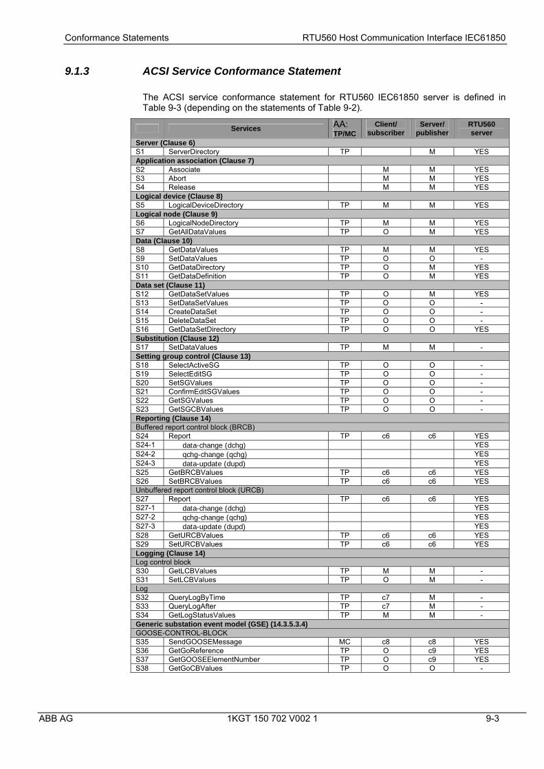
9.1.3 ACSI Service Conformance Statement
The ACSI service conformance statement for RTU560 IEC61850 server is defined in Table 9-3 (depending on the statements of Table 9-2).
Services AA: TP/MC
Client/ subscriber
Server/ publisher
RTU560 server
Server (Clause 6) S1 ServerDirectory TP M YES Application association (Clause 7) S2 Associate M M YES S3 Abort M M YES S4 Release M M YES Logical device (Clause 8) S5 LogicalDeviceDirectory TP M M YES Logical node (Clause 9) S6 LogicalNodeDirectory TP M M YES S7 GetAllDataValues TP O M YES Data (Clause 10) S8 GetDataValues TP M M YES S9 SetDataValues TP O O - S10 GetDataDirectory TP O M YES S11 GetDataDefinition TP O M YES Data set (Clause 11) S12 GetDataSetValues TP O M YES S13 SetDataSetValues TP O O - S14 CreateDataSet TP O O - S15 DeleteDataSet TP O O - S16 GetDataSetDirectory TP O O YES Substitution (Clause 12) S17 SetDataValues TP M M - Setting group control (Clause 13) S18 SelectActiveSG TP O O - S19 SelectEditSG TP O O - S20 SetSGValues TP O O - S21 ConfirmEditSGValues TP O O - S22 GetSGValues TP O O - S23 GetSGCBValues TP O O - Reporting (Clause 14) Buffered report control block (BRCB) S24 Report TP c6 c6 YES S24-1 data-change (dchg) YES S24-2 qchg-change (qchg) YES S24-3 data-update (dupd) YES S25 GetBRCBValues TP c6 c6 YES S26 SetBRCBValues TP c6 c6 YES Unbuffered report control block (URCB) S27 Report TP c6 c6 YES S27-1 data-change (dchg) YES S27-2 qchg-change (qchg) YES S27-3 data-update (dupd) YES S28 GetURCBValues TP c6 c6 YES S29 SetURCBValues TP c6 c6 YES Logging (Clause 14) Log control block S30 GetLCBValues TP M M - S31 SetLCBValues TP O M - Log S32 QueryLogByTime TP c7 M - S33 QueryLogAfter TP c7 M - S34 GetLogStatusValues TP M M - Generic substation event model (GSE) (14.3.5.3.4) GOOSE-CONTROL-BLOCK S35 SendGOOSEMessage MC c8 c8 YES S36 GetGoReference TP O c9 YES S37 GetGOOSEElementNumber TP O c9 YES S38 GetGoCBValues TP O O -

Conformance Statements RTU560 Host Communication Interface IEC61850
9-4 1KGT 150 702 V002 1 ABB AG
S39 SetGoCBValues TP O O - GSSE-CONTROL-BLOCK S40 SendGSSEMessage MC c8 c8 - S41 GetGsReference TP O c9 - S42 GetGSSEElementNumber TP O c9 - S43 GetGsCBValues TP O O - S44 SetGsCBValues TP O O - Transmission of sampled value model (SVC) (Clause 16) Multicast SVC S45 SendMSVMessage MC c10 c10 - S46 GetMSVCBValues TP O O - S47 SetMSVCBValues TP O O - Unicast SVC S48 SendUSVMessage TP c10 c10 - S49 GetUSVCBValues TP O O - S50 SetUSVCBValues TP O O - Control (17.5.1) S51 Select TP M O YES S52 SelectWithValue TP M O YES S53 Cancel TP O O YES S54 Operate TP M M YES S55 Command-Termination TP M O YES S56 TimeActivated-Operate TP O O - File transfer (Clause 20) S57 GetFile TP O M - S58 SetFile TP O O - S59 DeleteFile TP O O - S60 GetFileAttributeValues TP O M - Time (5.5) T1 Time resolution of internal clock Nearest
negative power of 2 in seconds
T2 Time accuracy of internal clock T1 T3 Supported TimeStamp resolution Nearest value
of 2**-n in seconds according to 5.5.3.7.3.3
c6 – shall declare support for at least one (BRCB or URCB) c7 – shall declare support for at least one (QueryLogByTime or QueryLogAfter) c8 – shall declare support for at least one (SendGOOSEMessage or SendGSSEMessage) c9 – shall declare support if TP association is available c10 – shall declare support for at least one (SendMSVMessage or SendUSVMessage) O – Optional
Table 9-3: ACSI service conformance statement
9.1.4 Specific Communication Service Mapping (SCSM)
See B21 Table 9-1 and [IEC61850-7-2].

Conformance Statements RTU560 Host Communication Interface IEC61850
ABB AG 1KGT 150 702 V002 1 9-5
9.2 Protocol Implementation Conformance Statement (PICS)
9.2.1 Basic Profile Conformance
9.2.1.1 PICS for A-Profile support
The PICS for A-Profile support for RTU560 IEC61850 server are defined in Table 9-4.
A-Profile shortcut
Profile Description Server RTU560 server
A1 Client/server A-Profile c1 YES A2 GOOSE/GSE management A-Profile c2 YES
(GOOSE only) A3 GSSE A-Profile c3 - A4 TimeSync A-Profile c4 -
c1 Shall be ‘m’ if support for any service specified in [IEC61850-8-1] Table 2 are declared within the ACSI basic conformance statement (see Table 5). c2 Shall be ‘m’ if support for any service specified in [IEC61850-8-1] Table 6 are declared within the ACSI basic conformance statement (see Table 5). c3 Shall be ‘m’ if support for any service specified in [IEC61850-8-1] Table 9 are declared within the ACSI basic conformance statement (see Table 5). c4 Support for at least one other A-Profile shall be declared (e.g. in A1-A3) in order to claim conformance to [IEC61850-8-1].
Table 9-4: PICS for A-Profile support
9.2.1.2 PICS for T-Profile support
The PICS for T-Profile support for RTU560 IEC61850 server are defined in Table 9-5.
T-Profile shortcut
Profile Description Server RTU560 server
T1 TCP/IP T-Profile c1 YES T2 OSI T-Profile c2 - T3 GOOSE/GSE T-Profile c3 YES
(GOOSE only) T4 GSSE T-Profile c4 - T5 TimeSync T-Profile O -
c1 Shall be ‘m’ if support for table 9-4 A1 is declared. Otherwise, shall be 'i'. c2 Shall be ‘o’ if support for table 9-4 A1 is declared. Otherwise, shall be 'i'. c3 Shall be ‘m’ if support for table 9-4 A2 is declared. Otherwise, shall be 'i'. c4 Shall be ‘m’ if support for table 9-4 A3 is declared. Otherwise, shall be 'i'. i – out-of-scope: The implementation of the item is not within the scope of this standard O – Optional
Table 9-5: PICS for T-Profile support
9.2.2 MMS Conformance
All needed services supporting the ACSI services stated to be supported in chapter ’9.1.3 ACSI Service Conformance Statement’ are supported by the MMS stack used.

Conformance Statements RTU560 Host Communication Interface IEC61850
9-6 1KGT 150 702 V002 1 ABB AG
9.3 Model Implementation Conformance Statement (MICS)
Table 9-5 defines the list of logical nodes supported by RTU560 IEC61850 server.
LN Group L: System logical nodes LPHD Physical device information LLN0 Logical node zero LN Group C: Logical nodes for control CSWI Switch controller CILO Interlocking CRSV Reservation CALH Alarm handling LN Group G: Logical nodes for generic references GAPC Generic automatic process control GGIO Generic process I/O LN Group M: Logical nodes for metering and measurement MMTR Metering MMXN Measurement MMXU Measurement LN Group P: Logical nodes for protection functions PTOC Time over current PDIS Distance PDIF Differential PTOF Over frequency PTUF Under frequency PTOV Over voltage PTUV Under voltage PSDE Sensitive directional earth fault PTEF Transient earth fault PSCH Protection scheme PTRC Protection trip conditioning LN Group R: Logical Nodes for protection related functions RBRF Breaker failure RREC Auto reclosing RSYN Synchronism-check or synchronising LN Group S: Logical Nodes for sensors and monitoring SIMG Insulation medium supervision (gas) SIML Insulation medium supervision (liquid) LN Group X: Logical Nodes for switchgear XCBR Circuit breaker XSWI Circuit switch LN Group Y: Logical Nodes for power transformer YLTC Tap changer YEFN Earth fault neutralizer (Petersen coil) LN Group Z: Logical Nodes for further power system equipment ZAXN Auxiliary network
Table 9-6: Logical nodes supported by the RTU560 IEC61850 server

Conformance Statements RTU560 Host Communication Interface IEC61850
ABB AG 1KGT 150 702 V002 1 9-7
9.3.1 LN Group L: System logical nodes
9.3.1.1 LN type: LPHD
LPHD Attribute Name Attribute Type Explanation LNName Shall be inherited from LN Class (see [IEC61850-7-2]) Data PhyNam DPL Physical device name plate PhyHealth INS Physical device health Proxy SPS Indicates if this LN is a proxy
Table 9-7: Logical node type LPHD
9.3.1.2 LN type: LLN0
LLN0 Attribute Name Attribute Type Explanation LNName Shall be inherited from LN Class (see [IEC61850-7-2]) Data
Common logical node information Mod INC Mode Beh INS Behaviour Health INS Health NamPlt LPL Name plate Loc SPS Local operation for complete logical device
Table 9-8: Logical node type LLN0

Conformance Statements RTU560 Host Communication Interface IEC61850
9-8 1KGT 150 702 V002 1 ABB AG
9.3.2 LN Group C: Logical nodes for control
9.3.2.1 LN type: CSWI
CSWI Attribute Name Attribute Type Explanation LNName Shall be inherited from LN Class (see [IEC61850-7-2]) Data
Common logical node information Mod INC Mode Beh INS Behaviour Health INS Health NamPlt LPL Name plate Loc SPS Local operation
Controls Pos DPC Double point controllable status output
Table 9-9: Logical node type CSWI
9.3.2.2 LN type: CILO
CILO Attribute Name Attribute Type Explanation LNName Shall be inherited from LN Class (see [IEC61850-7-2]) Data
Common logical node information Mod INC Mode Beh INS Behaviour Health INS Health NamPlt LPL Name plate
Status Information EnaOpn SPS Enable Open EnaCls SPS Enable Close
Table 9-10: Logical node type CILO
9.3.2.3 LN type: CALH
CALH Attribute Name Attribute Type Explanation LNName Shall be inherited from LN Class (see [IEC61850-7-2]) Data
Common logical node information Mod INC Mode Beh INS Behaviour Health INS Health NamPlt LPL Name plate
Status Information GrAlm SPS Group alarm
Table 9-11: Logical node type CALH

Conformance Statements RTU560 Host Communication Interface IEC61850
ABB AG 1KGT 150 702 V002 1 9-9
9.3.3 LN Group G: Logical nodes for generic references
9.3.3.1 LN type: GAPC
PTOC Attribute Name Attribute Type Explanation LNName Shall be inherited from LN Class (see [IEC61850-7-2]) Data
Common logical node information Mod INC Mode Beh INS Behaviour Health INS Health NamPlt LPL Name plate
Status information Str ACD Start Op ACT Operate
Table 9-12: Logical node type GAPC
Table 9-12 defines the specific logical nodes extensions for generic process I/O.
LN Group G: Logical nodes for generic references GGIO: Generic process I/O LN Prefix LN Class LN Type Description
Status information SP GGIO SPGGIO Generic single point status SP8 GGIO SP8GGIO Generic single point status (8 inputs) SP16 GGIO SP16GGIO Generic single point status (16 inputs) DP GGIO DPGGIO Generic double point status DP8 GGIO DP8GGIO Generic double point status (8 inputs) INS GGIO INSGGIO Generic integer status BCR GGIO BCRGGIO Generic binary counter reading
Measured information MV GGIO MVGGIO Generic measured value input MV8 GGIO MV8GGIO Generic measured value input (8 inputs) CMV GGIO CMVGGIO Generic complex measured value input
Controllable status information SC GGIO SCGGIO Generic single command SC8 GGIO SC8GGIO Generic single command (8 outputs) SC16 GGIO SC16GGIO Generic single command (16 outputs) DC GGIO DCGGIO Generic double command DC8 GGIO DC8GGIO Generic double command (8 outputs) INC GGIO INCGGIO Generic integer status output BSC GGIO BSCGGIO Generic binary controlled step position output
Table 9-13: Generic logical node supported by RTU560 server

Conformance Statements RTU560 Host Communication Interface IEC61850
9-10 1KGT 150 702 V002 1 ABB AG
9.3.4 Monitoring status information
9.3.4.1 LN type: SPGGIO
SPGGIO Attribute Name Attribute Type Explanation LNName Shall be inherited from LN Class (see [IEC61850-7-2]) Data
Common logical node information Mod INC Mode Beh INS Behaviour Health INS Health NamPlt LPL Name plate
Status information Ind SPS General indication (binary input)
Table 9-14: Logical node type SPGGIO
9.3.4.2 LN type: SP8GGIO
SP8GGIO Attribute Name Attribute Type Explanation LNName Shall be inherited from LN Class (see [IEC61850-7-2]) Data
Common logical node information Mod INC Mode Beh INS Behaviour Health INS Health NamPlt LPL Name plate
Status information Ind1 SPS General indication (binary input) Ind2 SPS General indication (binary input) Ind3 SPS General indication (binary input) Ind4 SPS General indication (binary input) Ind5 SPS General indication (binary input) Ind6 SPS General indication (binary input) Ind7 SPS General indication (binary input) Ind8 SPS General indication (binary input)
Table 9-15: Logical node type SP8GGIO
Conformance Statements RTU560 Host Communication Interface IEC61850
ABB AG 1KGT 150 702 V002 1 9-11
9.3.4.3 LN type: SP16GGIO
SP16GGIO Attribute Name Attribute Type Explanation LNName Shall be inherited from LN Class (see [IEC61850-7-2]) Data
Common logical node information Mod INC Mode Beh INS Behaviour Health INS Health NamPlt LPL Name plate
Status information Ind1 SPS General indication (binary input) Ind2 SPS General indication (binary input) Ind3 SPS General indication (binary input) Ind4 SPS General indication (binary input) Ind5 SPS General indication (binary input) Ind6 SPS General indication (binary input) Ind7 SPS General indication (binary input) Ind8 SPS General indication (binary input) Ind9 SPS General indication (binary input) Ind10 SPS General indication (binary input) Ind11 SPS General indication (binary input) Ind12 SPS General indication (binary input) Ind13 SPS General indication (binary input) Ind14 SPS General indication (binary input) Ind15 SPS General indication (binary input) Ind16 SPS General indication (binary input)
Table 9-16: Logical node type SP16GGIO
9.3.4.4 LN type: DPGGIO
DPGGIO Attribute Name Attribute Type Explanation LNName Shall be inherited from LN Class (see [IEC61850-7-2]) Data
Common logical node information Mod INC Mode Beh INS Behaviour Health INS Health NamPlt LPL Name plate
Status information DPI DPS Double point input
Table 9-17: Logical node type DPGGIO

Conformance Statements RTU560 Host Communication Interface IEC61850
9-12 1KGT 150 702 V002 1 ABB AG
9.3.4.5 LN type: DP8GGIO
DP8GGIO Attribute Name Attribute Type Explanation LNName Shall be inherited from LN Class (see [IEC61850-7-2]) Data
Common logical node information Mod INC Mode Beh INS Behaviour Health INS Health NamPlt LPL Name plate
Status information DPI1 DPS Double point input DPI2 DPS Double point input DPI3 DPS Double point input DPI4 DPS Double point input DPI5 DPS Double point input DPI6 DPS Double point input DPI7 DPS Double point input DPI8 DPS Double point input
Table 9-18: Logical node type DP8GGIO
9.3.4.6 LN type: INSGGIO
INSGGIO Attribute Name Attribute Type Explanation LNName Shall be inherited from LN Class (see [IEC61850-7-2]) Data
Common logical node information Mod INC Mode Beh INS Behaviour Health INS Health NamPlt LPL Name plate
Status information IntIn INS Integer status input
Table 9-19: Logical node type INSGGIO
9.3.4.7 LN type: BCRGGIO
BCRGGIO Attribute Name Attribute Type Explanation LNName Shall be inherited from LN Class (see [IEC61850-7-2]) Data
Common logical node information Mod INC Mode Beh INS Behaviour Health INS Health NamPlt LPL Name plate
Status information ITI BCR Integrated totals input
Table 9-20: Logical node type BCRGGIO

Conformance Statements RTU560 Host Communication Interface IEC61850
ABB AG 1KGT 150 702 V002 1 9-13
9.3.5 Measured information
9.3.5.1 LN type: MVGGIO
MVGGIO Attribute Name Attribute Type Explanation LNName Shall be inherited from LN Class (see [IEC61850-7-2]) Data
Common logical node information Mod INC Mode Beh INS Behaviour Health INS Health NamPlt LPL Name plate
Measured vlaues AnIn MV Analog input
Table 9-21: Logical node type MVGGIO
9.3.5.2 LN type: MV8GGIO
MV8GGIO Attribute Name Attribute Type Explanation LNName Shall be inherited from LN Class (see [IEC61850-7-2]) Data
Common logical node information Mod INC Mode Beh INS Behaviour Health INS Health NamPlt LPL Name plate
Measured vlaues AnIn1 MV Analog Input AnIn2 MV Analog Input AnIn3 MV Analog Input AnIn4 MV Analog Input AnIn5 MV Analog Input AnIn6 MV Analog Input AnIn7 MV Analog Input AnIn8 MV Analog Input
Table 9-22: Logical node type MV8GGIO
9.3.5.3 LN type: CMVGGIO
CMVGGIO Attribute Name Attribute Type Explanation LNName Shall be inherited from LN Class (see [IEC61850-7-2]) Data
Common logical node information Mod INC Mode Beh INS Behaviour Health INS Health NamPlt LPL Name plate
Measured vlaues CVIn CMV Complex analog value Input
Table 9-23: Logical node type CMVGGIO

Conformance Statements RTU560 Host Communication Interface IEC61850
9-14 1KGT 150 702 V002 1 ABB AG
9.3.6 Controllable status information
9.3.6.1 LN type: SCGGIO
SCGGIO Attribute Name Attribute Type Explanation LNName Shall be inherited from LN Class (see [IEC61850-7-2]) Data
Common logical node information Mod INC Mode Beh INS Behaviour Health INS Health NamPlt LPL Name plate
Controls SPCSO SPC Single point controllable status output
Table 9-24: Logical node type SCGGIO
9.3.6.2 LN type: SC8GGIO
SC8GGIO Attribute Name Attribute Type Explanation LNName Shall be inherited from LN Class (see [IEC61850-7-2]) Data
Common logical node information Mod INC Mode Beh INS Behaviour Health INS Health NamPlt LPL Name plate
Controls SPCSO1 SPC Single point controllable status output SPCSO2 SPC Single point controllable status output SPCSO3 SPC Single point controllable status output SPCSO4 SPC Single point controllable status output SPCSO5 SPC Single point controllable status output SPCSO6 SPC Single point controllable status output SPCSO7 SPC Single point controllable status output SPCSO8 SPC Single point controllable status output
Table 9-25: Logical node type SC8GGIO
9.3.6.3 LN type: SC16GGIO
SC16GGIO Attribute Name Attribute Type Explanation LNName Shall be inherited from LN Class (see [IEC61850-7-2]) Data
Common logical node information Mod INC Mode Beh INS Behaviour Health INS Health NamPlt LPL Name plate
Controls SPCSO1 SPC Single point controllable status output SPCSO2 SPC Single point controllable status output SPCSO3 SPC Single point controllable status output SPCSO4 SPC Single point controllable status output SPCSO5 SPC Single point controllable status output SPCSO6 SPC Single point controllable status output SPCSO7 SPC Single point controllable status output SPCSO8 SPC Single point controllable status output SPCSO9 SPC Single point controllable status output SPCSO10 SPC Single point controllable status output SPCSO11 SPC Single point controllable status output

Conformance Statements RTU560 Host Communication Interface IEC61850
ABB AG 1KGT 150 702 V002 1 9-15
SPCSO12 SPC Single point controllable status output SPCSO13 SPC Single point controllable status output SPCSO14 SPC Single point controllable status output SPCSO15 SPC Single point controllable status output SPCSO16 SPC Single point controllable status output
Table 9-26: Logical node type SC16GGIO
9.3.6.4 LN type: DCGGIO
DCGGIO Attribute Name Attribute Type Explanation LNName Shall be inherited from LN Class (see [IEC61850-7-2]) Data
Common logical node information Mod INC Mode Beh INS Behaviour Health INS Health NamPlt LPL Name plate
Controls DPCSO DPC Double point controllable status output
Table 9-27: Logical node type DCGGIO
9.3.6.5 LN type: DC8GGIO
DC8GGIO Attribute Name Attribute Type Explanation LNName Shall be inherited from LN Class (see [IEC61850-7-2]) Data
Common logical node information Mod INC Mode Beh INS Behaviour Health INS Health NamPlt LPL Name plate
Controls DPCSO1 DPC Double point controllable status output DPCSO2 DPC Double point controllable status output DPCSO3 DPC Double point controllable status output DPCSO4 DPC Double point controllable status output DPCSO5 DPC Double point controllable status output DPCSO6 DPC Double point controllable status output DPCSO7 DPC Double point controllable status output DPCSO8 DPC Double point controllable status output
Table 9-28: Logical node type DC8GGIO
9.3.6.6 LN type: INCGGIO
INCGGIO Attribute Name Attribute Type Explanation LNName Shall be inherited from LN Class (see [IEC61850-7-2]) Data
Common logical node information Mod INC Mode Beh INS Behaviour Health INS Health NamPlt LPL Name plate
Controls ISCSO INC Integer status controllable status output
Table 9-29: Logical node type INCGGIO

Conformance Statements RTU560 Host Communication Interface IEC61850
9-16 1KGT 150 702 V002 1 ABB AG
9.3.6.7 LN type: BSCGGIO
BSCGGIO Attribute Name Attribute Type Explanation LNName Shall be inherited from LN Class (see [IEC61850-7-2]) Data
Common logical node information Mod INC Mode Beh INS Behaviour Health INS Health NamPlt LPL Name plate
Controls RCO BSC Regulation step command output
Table 9-30: Logical node type BSCGGIO

Conformance Statements RTU560 Host Communication Interface IEC61850
ABB AG 1KGT 150 702 V002 1 9-17
9.3.7 LN Group M: Logical nodes for metering and measurement
9.3.7.1 LN type: MMTR
MMTR Attribute Name Attribute Type Explanation LNName Shall be inherited from LN Class (see [IEC61850-7-2]) Data
Common logical node information Mod INC Mode Beh INS Behaviour Health INS Health NamPlt LPL Name plate
Metered values TotVAh BCR Net apparent energy since last reset TotWh BCR Net Real energy since last reset TotVArh BCR Net Reactive energy since last reset
Table 9-31: Logical node type MMTR
9.3.7.2 LN type: MMXN
MMXN Attribute Name Attribute Type Explanation LNName Shall be inherited from LN Class (see [IEC61850-7-2]) Data
Common logical node information Mod INC Mode Beh INS Behaviour Health INS Health NamPlt LPL Name plate
Measured values Amp MV Current I (rms) not allocated to a phase Vol MV Voltage V (rms) not allocated to a phase Watt MV Power (P) not allocated to a phase VolAmpr MV Reactive Power (Q) not allocated to a phase VolAmp MV Apparent Power (S) not allocated to a phase PwrFact MV Power Factor not allocated to a phase Imp CMV Impedance Hz MV Frequency
Table 9-32: Logical node type MMXN

Conformance Statements RTU560 Host Communication Interface IEC61850
9-18 1KGT 150 702 V002 1 ABB AG
9.3.7.3 LN type: MMXU
MMXU Attribute Name Attribute Type Explanation LNName Shall be inherited from LN Class (see [IEC61850-7-2]) Data
Common logical node information Mod INC Mode Beh INS Behaviour Health INS Health NamPlt LPL Name plate
Measured values TotW MV Total Active Power (Total P) TotVAr MV Total Reactive Power (Total Q) TotVA MV Total Apparent Power (Total S) TotPF MV Average Power factor (Total PF) Hz MV Frequency PPV DEL Phase to phase voltages (VL1VL2, …) PhV WYE Phase to ground voltages (VL1ER, …) A WYE Phase currents (IL1, IL2, IL3) W WYE Phase active power (P) Var WYE Phase reactive power (Q) VA WYE Phase apparent power (S) PF WYE Phase power factor Z WYE Phase Impedance
Table 9-33: Logical node type MMXU

Conformance Statements RTU560 Host Communication Interface IEC61850
ABB AG 1KGT 150 702 V002 1 9-19
9.3.8 LN Group P: Logical nodes for protection functions
9.3.8.1 LN type: PTOC
PTOC Attribute Name Attribute Type Explanation LNName Shall be inherited from LN Class (see [IEC61850-7-2]) Data
Common logical node information Mod INC Mode Beh INS Behaviour Health INS Health NamPlt LPL Name plate
Status information Str ACD Start Op ACT Operate
Table 9-34: Logical node type PTOC
9.3.8.2 LN type: PDIS
PDIS Attribute Name Attribute Type Explanation LNName Shall be inherited from LN Class (see [IEC61850-7-2]) Data
Common logical node information Mod INC Mode Beh INS Behaviour Health INS Health NamPlt LPL Name plate
Status information Str ACD Start Op ACT Operate
Table 9-35: Logical node type PDIS
9.3.8.3 LN type: PDIF
PDIF Attribute Name Attribute Type Explanation LNName Shall be inherited from LN Class (see [IEC61850-7-2]) Data
Common logical node information Mod INC Mode Beh INS Behaviour Health INS Health NamPlt LPL Name plate
Status information Op ACT Operate
Table 9-36: Logical node type PDIF

Conformance Statements RTU560 Host Communication Interface IEC61850
9-20 1KGT 150 702 V002 1 ABB AG
9.3.8.4 LN type: PTOF
PTOF Attribute Name Attribute Type Explanation LNName Shall be inherited from LN Class (see [IEC61850-7-2]) Data
Common logical node information Mod INC Mode Beh INS Behaviour Health INS Health NamPlt LPL Name plate
Status information Str ACD Start Op ACT Operate
Table 9-37: Logical node type PTOF
9.3.8.5 LN type: PTUF
PTUF Attribute Name Attribute Type Explanation LNName Shall be inherited from LN Class (see [IEC61850-7-2]) Data
Common logical node information Mod INC Mode Beh INS Behaviour Health INS Health NamPlt LPL Name plate
Status information Str ACD Start Op ACT Operate
Table 9-38: Logical node type PTUF
9.3.8.6 LN type: PTOV
PTOV Attribute Name Attribute Type Explanation LNName Shall be inherited from LN Class (see [IEC61850-7-2]) Data
Common logical node information Mod INC Mode Beh INS Behaviour Health INS Health NamPlt LPL Name plate
Status information Str ACD Start Op ACT Operate
Table 9-39: Logical node type PTOV
Conformance Statements RTU560 Host Communication Interface IEC61850
ABB AG 1KGT 150 702 V002 1 9-21
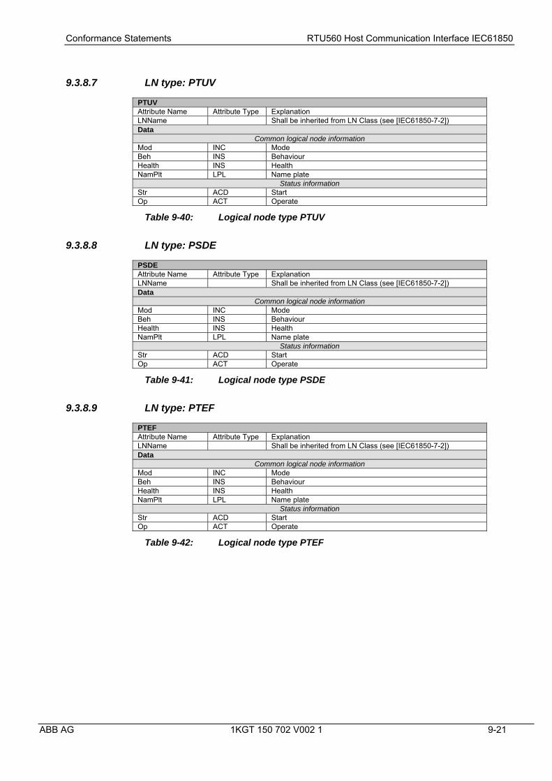
9.3.8.7 LN type: PTUV
PTUV Attribute Name Attribute Type Explanation LNName Shall be inherited from LN Class (see [IEC61850-7-2]) Data
Common logical node information Mod INC Mode Beh INS Behaviour Health INS Health NamPlt LPL Name plate
Status information Str ACD Start Op ACT Operate
Table 9-40: Logical node type PTUV
9.3.8.8 LN type: PSDE
PSDE Attribute Name Attribute Type Explanation LNName Shall be inherited from LN Class (see [IEC61850-7-2]) Data
Common logical node information Mod INC Mode Beh INS Behaviour Health INS Health NamPlt LPL Name plate
Status information Str ACD Start Op ACT Operate
Table 9-41: Logical node type PSDE
9.3.8.9 LN type: PTEF
PTEF Attribute Name Attribute Type Explanation LNName Shall be inherited from LN Class (see [IEC61850-7-2]) Data
Common logical node information Mod INC Mode Beh INS Behaviour Health INS Health NamPlt LPL Name plate
Status information Str ACD Start Op ACT Operate
Table 9-42: Logical node type PTEF

Conformance Statements RTU560 Host Communication Interface IEC61850
9-22 1KGT 150 702 V002 1 ABB AG
9.3.8.10 LN type: PSCH
PSCH Attribute Name Attribute Type Explanation LNName Shall be inherited from LN Class (see [IEC61850-7-2]) Data
Common logical node information Mod INC Mode Beh INS Behaviour Health INS Health NamPlt LPL Name plate
Status information ProTx SPS Teleprotection signal transmitted ProRx SPS Teleprotection signal received Str ACD Carrier Send Op ACT Operate
Table 9-43: Logical node type PSCH
9.3.8.11 LN type: PTRC
PTRC Attribute Name Attribute Type Explanation LNName Shall be inherited from LN Class (see [IEC61850-7-2]) Data
Common logical node information Mod INC Mode Beh INS Behaviour Health INS Health NamPlt LPL Name plate
Status information Op ACT Operate (combination of subscribed Op from protection
functions) Str ACD Sum of all starts of all connected Logical Nodes
Table 9-44: Logical node type PTRC

Conformance Statements RTU560 Host Communication Interface IEC61850
ABB AG 1KGT 150 702 V002 1 9-23
9.3.9 LN Group R: Logical nodes for protection related functions
9.3.9.1 LN type: RBRF
RBRF Attribute Name Attribute Type Explanation LNName Shall be inherited from LN Class (see [IEC61850-7-2]) Data
Common logical node information Mod INC Mode Beh INS Behaviour Health INS Health NamPlt LPL Name plate
Status information OpEx ACT Breaker failure trip (“external trip”) OpIn ACT Operate, retrip (“internal trip”)
Table 9-45: Logical node type RBRF
9.3.9.2 LN type: RREC
RREC Attribute Name Attribute Type Explanation LNName Shall be inherited from LN Class (see [IEC61850-7-2]) Data
Common logical node information Mod INC Mode Beh INS Behaviour Health INS Health NamPlt LPL Name plate
Status information Op ACT Operate (used here to provide close to XCBR) AutoRecSt INS Auto Reclosing Status
Table 9-46: Logical node type RREC
9.3.9.3 LN type: RSYN
RSYN Attribute Name Attribute Type Explanation LNName Shall be inherited from LN Class (see [IEC61850-7-2]) Data
Common logical node information Mod INC Mode Beh INS Behaviour Health INS Health NamPlt LPL Name plate
Status information Rel SPS Release
Table 9-47: Logical node type RSYN

Conformance Statements RTU560 Host Communication Interface IEC61850
9-24 1KGT 150 702 V002 1 ABB AG
9.3.10 LN Group S: Logical Nodes for sensors and monitoring
9.3.10.1 LN type: SIMG
SIMG Attribute Name Attribute Type Explanation LNName Shall be inherited from LN Class (see [IEC61850-7-2]) Data
Common logical node information Mod INC Mode Beh INS Behaviour Health INS Health NamPlt LPL Name plate
Status information InsAlm SPS Insulation gas critical (refill isolation medium) PresAlm SPS Isolation gas pressure alarm DenAlm SPS Isolation gas density alarm TmpAlm SPS Isolation gas temperature alarm
Table 9-48: Logical node type SIMG
9.3.10.2 LN type: SIML
SIML Attribute Name Attribute Type Explanation LNName Shall be inherited from LN Class (see [IEC61850-7-2]) Data
Common logical node information Mod INC Mode Beh INS Behaviour Health INS Health NamPlt LPL Name plate
Status information InsAlm SPS Insulation gas critical (refill isolation medium) TmpAlm SPS Insulation liquid temperature alarm PresTr SPS Insulation liquid pressure trip PresAlm SPS Insulation liquid pressure alarm
Table 9-49: Logical node type SIML

Conformance Statements RTU560 Host Communication Interface IEC61850
ABB AG 1KGT 150 702 V002 1 9-25
9.3.11 LN Group X: Logical nodes for switchgear
9.3.11.1 LN type: XCBR
XCBR Attribute Name Attribute Type Explanation LNName Shall be inherited from LN Class (see [IEC61850-7-2]) Data
Common logical node information Mod INC Mode Beh INS Behaviour Health INS Health NamPlt LPL Name plate Loc SPS Local operation (local means without substation automation
communication, hardwired direct control) EEHealth INS External equipment health OpCnt INS Operation counter
Controls Pos DPC Switch position BlkOpn SPC Block opening BlkCls SPC Block closing
Status information CBOpCap INS Circuit breaker operating capability
Table 9-50: Logical node type XCBR
9.3.11.2 LN type: XSWI
XSWI Attribute Name Attribute Type Explanation LNName Shall be inherited from LN Class (see [IEC61850-7-2]) Data
Common logical node information Mod INC Mode Beh INS Behaviour Health INS Health NamPlt LPL Name plate Loc SPS Local operation (local means without substation automation
communication, hardwired direct control) EEHealth INS External equipment health OpCnt INS Operation counter
Controls Pos DPC Switch position BlkOpn SPC Block opening BlkCls SPC Block closing
Status informaton SwTyp INS Switch type SwOpCap INS Switch operating capability
Table 9-51: Logical node type XSWI

Conformance Statements RTU560 Host Communication Interface IEC61850
9-26 1KGT 150 702 V002 1 ABB AG
9.3.12 LN Group Y: Logical nodes for power transformer
9.3.12.1 LN type: YLTC
YLTC Attribute Name Attribute Type Explanation LNName Shall be inherited from LN Class (see [IEC61850-7-2]) Data
Common logical node information Mod INC Mode Beh INS Behaviour Health INS Health NamPlt LPL Name plate EEHealth INS External equipment health
Controls TapChg BSC Change Tap Position (stop, higher, lower)
Status informaton EndPosR SPS End position raise reached EndPosL SPS End position lower reached
Table 9-52: Logical node type YLTC
9.3.12.2 LN type: YEFN
YEFN Attribute Name Attribute Type Explanation LNName Shall be inherited from LN Class (see [IEC61850-7-2]) Data
Common logical node information Mod INC Mode Beh INS Behaviour Health INS Health NamPlt LPL Name plate EEHealth INS External equipment health Loc SPS Local operation
Measured Values ECA MV Earth coil current
Controls ColTapPos ISC End position raise reached
Table 9-53: Logical node type YEFN

Conformance Statements RTU560 Host Communication Interface IEC61850
ABB AG 1KGT 150 702 V002 1 9-27
9.3.13 LN Group Z: Logical Nodes for further power system equipment
9.3.13.1 LN type: ZAXN
ZAXN Attribute Name Attribute Type Explanation LNName Shall be inherited from LN Class (see [IEC61850-7-2]) Data
Common logical node information Mod INC Mode Beh INS Behaviour Health INS Health NamPlt LPL Name plate EEHealth INS External equipment health
Table 9-54: Logical node type ZAXN


