Embed Size (px)
Citation preview
START-UP AND INSTALLATION MANUAL
DOCUMENT - TECO-E510IMVer 01: 2015.08
230V Class 1~ IP66/NEMA 4X 0.4 - 2.2 kW / 0.5 - 3 HP
230V Class 3~ IP66/NEMA 4X 0.4 - 15 kW / 0.75 - 20 HP
460V 460V Class 3~ IP66/NEMA 4X 0.45- 18.5 kW / 1 - 25 HP
Read all operating instructions before installing, connecting (wiring), operating, servicing, or inspectingthe inverter.
Ensure that this manual is made available to the end user ofthe inverter.
Store this manual in a safe, convenient location.
TThe manual is subject to change without prior notice.
Refer to the E510 Instruction Manual (www.tecowestinghouse.com).
E510INVERTER
**** STATEMENT ****
Si Desea descargar el manual en español diríjase a este Link: www.tecowestinghouse.com
Table of Contents
Preface ........................................................................................................................................................... 0-1
1 Safety Precautions ..................................................................................................................................... 1-1
1.1 Before Supplying Power to the Inverter .................................................................................................... 1-1
1.2 Wiring ........................................................................................................................................................ 1-2
1.3 Before Operation ....................................................................................................................................... 1-3
1.4 Parameters Setting ................................................................................................................................... 1-3
1.5 Operation .................................................................................................................................................. 1-4
1.6 Maintenance, Inspection and Replacement .............................................................................................. 1-5
1.7 Disposal of the Inverter ............................................................................................................................. 1-5
1 Consignes de sécurité (Français) ............................................................................................................ 1-6
1.1 Avant d'alimenter le disque dur ................................................................................................................. 1-6
1.2 Câblage ..................................................................................................................................................... 1-6
1.3 Avant l'opération........................................................................................................................................ 1-7
1.4 Configuration Paramètre ........................................................................................................................... 1-7
1.5 Opération .................................................................................................................................................. 1-8
1.6 Entretien, Inspection et remplacement ..................................................................................................... 1-8
1.7 Mise au rebut du variateur ........................................................................................................................ 1-9
2 Model Description ...................................................................................................................................... 2-1
2.1 Nameplate Data ........................................................................................................................................ 2-1
2.2 Inverter Models – Motor Power Rating ..................................................................................................... 2-2
3 Environment and Installation .................................................................................................................... 3-1
3.1 Environment .............................................................................................................................................. 3-1
3.2 Warning Labels ......................................................................................................................................... 3-2
3.3 Removing the Front Cover and Keypad.................................................................................................... 3-3
3.4 Inverter Exterior ......................................................................................................................................... 3-5
3.5 Wire Gauges, Tightening Torque and Short Circuit Rating ...................................................................... 3-8
3.6 Wiring Peripheral Power Devices ............................................................................................................. 3-9
3.7 General Wiring Diagram .......................................................................................................................... 3-11
3.8 User Terminals ........................................................................................................................................ 3-12
3.9 Power Terminals ..................................................................................................................................... 3-15
3.10 Inverter Wiring ....................................................................................................................................... 3-17
3.11 Input Power and Motor Cable Length ................................................................................................... 3-19
3.12 Cable Length vs, Carrier Frequency ..................................................................................................... 3-19
3.13 Installing an AC Line Reactor ............................................................................................................... 3-19
3.14 Power Input Wire Size and NFB ........................................................................................................... 3-20
3.15 Control Circuit Wiring ............................................................................................................................ 3-20
3.16 Inverter Specifications ........................................................................................................................... 3-21
3.17 General Specifications .......................................................................................................................... 3-24
3.18 Inverter De-rating Based on Carrier Frequency .................................................................................... 3-26
3.19 Inverter Dimensions .............................................................................................................................. 3-27
4. Keypad and Programming Functions ..................................................................................................... 4-1
4.1 LED Keypad .............................................................................................................................................. 4-1
4.2 Parameters ................................................................................................................................................ 4-8
4.3 Description of Parameters ...................................................................................................................... 4-27
5. Check Motor Rotation and Direction ....................................................................................................... 5-1
6. Speed Reference Command Configuration............................................................................................ 6-1
6.1 Reference from the Keypad ...................................................................................................................... 6-1
6.2 Reference from an Analog Signal (0-10V / 4-20mA) / Speed Pot ............................................................ 6-2
6.3 Reference from Serial Communication RS485 ......................................................................................... 6-4
6.4 Reference from Pulse Input ...................................................................................................................... 6-6
6.5 Change Frequency Unit from Hz to rpm ................................................................................................... 6-7
7. Operation Method Configuration (Run / Stop) ....................................................................................... 7-1
7.1 Run / Stop from the Keypad ...................................................................................................................... 7-1
7.2 Run / Stop from External Switch / Contact or Pushbutton ........................................................................ 7-2
7.3 Run / Stop from Serial Communication RS485 ........................................................................................ 7-4
8. Motor and Application Specific Settings ................................................................................................ 8-1
8.1 Set Motor Nameplate Data ....................................................................................................................... 8-1
8.2 Acceleration and Deceleration Time ......................................................................................................... 8-2
8.3 Volt/Hz Curve Modification (Torque Boost)............................................................................................... 8-3
8.4 Rapid Stop ................................................................................................................................................ 8-4
8.5 Forward and Reverse Jog ......................................................................................................................... 8-5
8.6 Analog Output Setup ................................................................................................................................. 8-6
9. Using PID Control for Constant Flow / Pressure Applications ............................................................ 9-1
9.1 What is PID Control ................................................................................................................................... 9-1
9.2 Connect Transducer Feedback Signal .................................................................................................... 9-3
9.3 Engineering Units ...................................................................................................................................... 9-4
9.4 Sleep / Wakeup Function .......................................................................................................................... 9-5
10 Troubleshooting, Fault Diagnostics and Maintenance ...................................................................... 10-1
10.1 General ................................................................................................................................................. 10-1
10.2 Fault Detection Function ....................................................................................................................... 10-1
10.3 General Troubleshooting ...................................................................................................................... 10-6
10.4 Routine and Periodic Inspection ........................................................................................................... 10-7
10.5 Routine Maintenance .......................................................................................................................... 10-10
14. Commonly Used Parameters ............................................................................................................... 11-1
00-02 Run command selection ..................................................................................................................... 11-1
00-05 Main Frequency Command Source Selection .................................................................................... 11-3
00-14 Acceleration time 1 ............................................................................................................................. 11-5
00-15 Deceleration time 1 ............................................................................................................................. 11-5
01-00 V/f curve selection ............................................................................................................................... 11-6
03-00 ~ 03-05 Multi-function terminal function .............................................................................................. 11-9
03-11 ~ 03-12 Relay (R1A-R1C / R2A-R2C) output ................................................................................... 11-18
03-13 Frequency detection level ................................................................................................................. 11-20
03-14 Frequency detection width ................................................................................................................ 11-20
04-11 Analog Voltage & Current Input Selections AI1/AI2 ......................................................................... 11-21
04-02 ~ 04-10 Analog Input Parameters ..................................................................................................... 11-22
04-11 Analog Output A01 Function Selection ............................................................................................. 11-25
07-00 Momentary Power Loss and Restart ................................................................................................ 11-26
07-01 Auto Restart Delay Time ................................................................................................................... 11-26
07-02 Number of Auto Restart Attempts ..................................................................................................... 11-26
08-00 Trip Prevention Selection .................................................................................................................. 11-27
08-01 ~ 08-05 Trip Prevention Parameters ................................................................................................ 11-27
12-00 Display Mode .................................................................................................................................... 11-28
12-01 ~ 12-05 Display Scaling and Custom Unit Parameters .................................................................... 11-28
13-02 Fault Log Display / Fault Log Clearance Function ............................................................................ 11-30
13-08 Reset Drive to Factory Settings ........................................................................................................ 11-30
Appendix A: UL Instructions........................................................................................................................ A1
1-1
1. Safety Precautions (English)
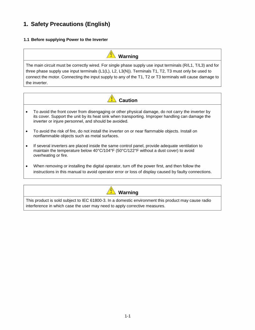
1.1 Before supplying Power to the Inverter
Warning
The main circuit must be correctly wired. For single phase supply use input terminals (R/L1, T/L3) and for
three phase supply use input terminals (L1(L), L2, L3(N)). Terminals T1, T2, T3 must only be used to
connect the motor. Connecting the input supply to any of the T1, T2 or T3 terminals will cause damage to
the inverter.
Caution
To avoid the front cover from disengaging or other physical damage, do not carry the inverter by its cover. Support the unit by its heat sink when transporting. Improper handling can damage the inverter or injure personnel, and should be avoided.
To avoid the risk of fire, do not install the inverter on or near flammable objects. Install on nonflammable objects such as metal surfaces.
If several inverters are placed inside the same control panel, provide adequate ventilation to maintain the temperature below 40°C/104°F (50°C/122°F without a dust cover) to avoid overheating or fire.
When removing or installing the digital operator, turn off the power first, and then follow the
instructions in this manual to avoid operator error or loss of display caused by faulty connections.
Warning
This product is sold subject to IEC 61800-3. In a domestic environment this product may cause radio
interference in which case the user may need to apply corrective measures.
1-2
1.2 Wiring
Warning
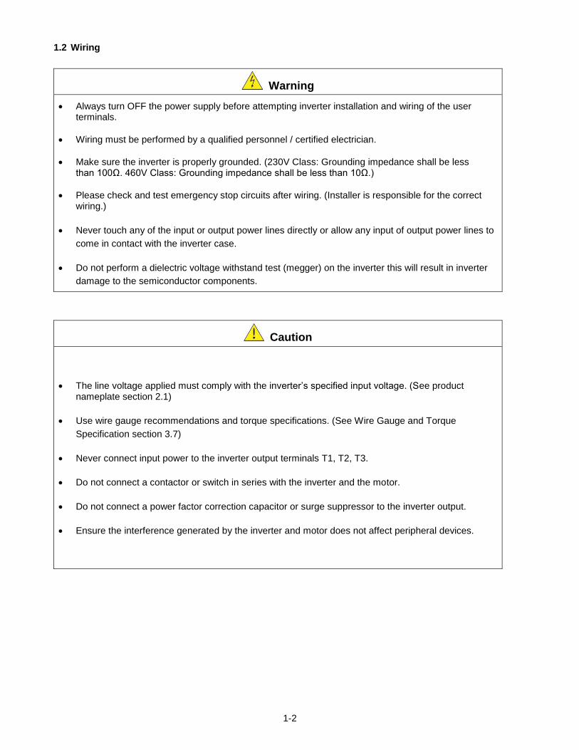
Always turn OFF the power supply before attempting inverter installation and wiring of the user terminals.
Wiring must be performed by a qualified personnel / certified electrician.
Make sure the inverter is properly grounded. (230V Class: Grounding impedance shall be less than 100Ω. 460V Class: Grounding impedance shall be less than 10Ω.)
Please check and test emergency stop circuits after wiring. (Installer is responsible for the correct wiring.)
Never touch any of the input or output power lines directly or allow any input of output power lines to
come in contact with the inverter case.
Do not perform a dielectric voltage withstand test (megger) on the inverter this will result in inverter
damage to the semiconductor components.
Caution
The line voltage applied must comply with the inverter’s specified input voltage. (See product nameplate section 2.1)
Use wire gauge recommendations and torque specifications. (See Wire Gauge and Torque
Specification section 3.7)
Never connect input power to the inverter output terminals T1, T2, T3.
Do not connect a contactor or switch in series with the inverter and the motor.
Do not connect a power factor correction capacitor or surge suppressor to the inverter output.
Ensure the interference generated by the inverter and motor does not affect peripheral devices.
1-3
1.3 Before Operation
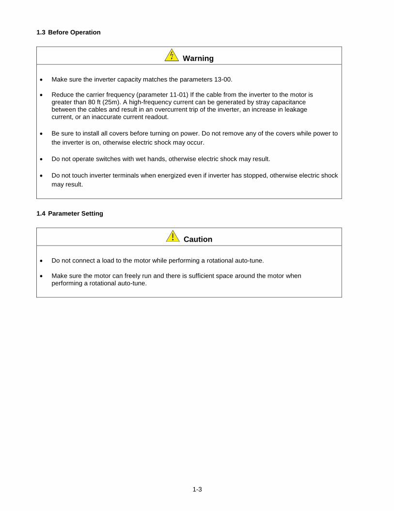
Warning
Make sure the inverter capacity matches the parameters 13-00.
Reduce the carrier frequency (parameter 11-01) If the cable from the inverter to the motor is greater than 80 ft (25m). A high-frequency current can be generated by stray capacitance between the cables and result in an overcurrent trip of the inverter, an increase in leakage current, or an inaccurate current readout.
Be sure to install all covers before turning on power. Do not remove any of the covers while power to
the inverter is on, otherwise electric shock may occur.
Do not operate switches with wet hands, otherwise electric shock may result.
Do not touch inverter terminals when energized even if inverter has stopped, otherwise electric shock
may result.
1.4 Parameter Setting
Caution
Do not connect a load to the motor while performing a rotational auto-tune.
Make sure the motor can freely run and there is sufficient space around the motor when performing a rotational auto-tune.
1-4
1.5 Operation
Warning
Be sure to install all covers before turning on power. Do not remove any of the covers while power to
the inverter is on, otherwise electric shock may occur.
Do not connect or disconnect the motor during operation. This will cause the inverter to trip and may cause damage to the inverter.
Operations may start suddenly if an alarm or fault is reset with a run command active. Confirm that no run command is active upon resetting the alarm or fault, otherwise accidents may occur.
Do not operate switches with wet hands, otherwise electric shock may result.
It provides an independent external hardware emergency switch, which emergently shuts down the
inverter output in the case of danger.
If automatic restart after power recovery (parameter 07-00) is enabled, the inverter will start
automatically after power is restored.
Make sure it is safe to operate the inverter and motor before performing a rotational auto-tune.
Do not touch inverter terminals when energized even if inverter has stopped, otherwise electric shock may result.
Do not check signals on circuit boards while the inverter is running.
After the power is turned off, the cooling fan may continue to run for some time.
Caution
Do not touch heat-generating components such as heat sinks and braking resistors.
Carefully check the performance of motor or machine before operating at high speed, otherwise Injury may result.
Note the parameter settings related to the braking unit when applicable.
Do not use the inverter braking function for mechanical holding, otherwise injury may result.
Do not check signals on circuit boards while the inverter is running.
1-5
1.6 Maintenance, Inspection and Replacement
Warning
Wait a minimum of five minutes after power has been turned OFF before starting an inspection. Also
confirm that the charge light is OFF and that the DC bus voltage has dropped below 25Vdc.
Never touch high voltage terminals in the inverter.
Make sure power to the inverter is disconnected before disassembling the inverter.
Only authorized personnel should perform maintenance, inspection, and replacement operations.
(Take off metal jewelry such as watches and rings and use insulated tools.)
Caution
The Inverter can be used in an environment with a temperature range from 14° -104°F (-10-40°C) and relative humidity of 95% non-condensing.
The inverter must be operated in a dust, gas, mist and moisture free environment.
1.7 Disposal of the Inverter
Caution
Please dispose of this unit with care as an industrial waste and according to your required local regulations.
The capacitors of inverter main circuit and printed circuit board are considered as hazardous waste and must not be burned.
The Plastic enclosure and parts of the inverter such as the top cover board will release harmful gases if burned.
1-6
1. Consignes de sécurité (Français)
1.1 Avant d'alimenter le disque dur
Avertissement
Le circuit principal doit être correctement câblée. Pour les terminaux monophasés d'approvisionnement
de l'utilisation des intrants (R/L1, T/L3) et de trois bornes d'entrée de l'utilisation de l'offre de phase (R/L1,
S/L2, T/L3). U/T1, V/T2, W/T3 ne doivent être utilisés pour connecter le moteur. Raccordement de
l'alimentation d'entrée à l'un des U/T1, V/T2 W/T3 ou bornes risque d'endommager le lecteur.
Attention
Pour éviter que le couvercle ne se désengage ou de tout autre dommage physique, ne portez pas le
lecteur par son couverture. Soutenir le groupe par son dissipateur de chaleur lors du transport. Une
mauvaise manipulation peut endommager le lecteur ou blesser le personnel, et doit être évitée.
Pour éviter que les risques d'incendie, ne pas installer le lecteur sur ou à proximité d'objets inflammables.
Installer sur des objets ininflammables comme les surfaces métalliques.
Si plusieurs disques sont placés dans le même panneau de contrôle, fournir une ventilation adéquate pour
maintenir la température en dessous de 40 ° C/104 ° F (50 ° C/122 ° F sans housse de protection) pour
éviter la surchauffe ou incendie.
Lors d'un retrait ou d'installation de l'opérateur numérique, éteignez-le d'abord, puis de suivre les
instructions de ce manuel pour éviter les erreurs de l'opérateur ou de la perte de l'affichage causé par des
connexions défectueuses.
Avertissement
Lors d'un retrait ou d'installation de l'opérateur numérique, éteignez-le d'abord, puis de suivre les
instructions de ce manuel pour éviter les erreurs de l'opérateur ou de la perte de l'affichage causé par des
connexions défectueuses....
1.2 Câblage
Avertissement
Coupez toujours l'alimentation électrique avant de procéder à l'installation d'entraînement et le câblage
des terminaux utilisateurs.
Le câblage doit être effectué par un personnel qualifié / électricien certifié.
Assurez-vous que le lecteur est correctement mis à la terre. (220V Classe: impédance de mise à la terre
doit être inférieure à 100Ω Classe 440V:. Impédance de mise à la terre doit être inférieure à 10Ω.)
vérifier et tester mes circuits d'arrêt d'urgence après le câblage. (L’Installateur est responsable du
câblage.)
Ne touchez jamais de l'entrée ou de lignes électriques de sortie permettant directement ou toute entrée ou
de lignes de puissance de sortie à venir en contact avec le boîtier d'entraînement.
Ne pas effectuer un test de tenue en tension diélectrique (mégohmmètre) sur le disque dur ou cela va
entraîner des dommages de lecture pour les composants semi-conducteurs.
1-7
Attention
La tension d'alimentation appliquée doit se conformer à la tension d'entrée spécifiée par le lecteur. (Voir la section signalétique du produit)
Raccorder la résistance de freinage et de l'unité de freinage sur les bornes assignées.
Ne pas brancher une résistance de freinage directement sur les bornes CC P (+) et N (-), sinon risque d'incendie.
Utilisez des recommandations de la jauge de fil et les spécifications de couple. (Voir Wire Gauge et la section de spécification de couple)。
Ne jamais brancher l'alimentation d'entrée aux bornes onduleur de sortie U/T1, V/T2, W/T3.
Ne pas brancher un contacteur ou interrupteur en série avec le variateur et le moteur.
Ne branchez pas un facteur condensateur de correction de puissance ou suppresseur de tension à la sortie du variateur。
S'assurer que l'interférence générée par l'entraînement et le moteur n'a pas d'incidence sur les périphériques.
1.3 Avant l'opération
Avertissement
Assurez-vous que la capacité du disque correspond aux paramètres de notation avant d'alimenter.
Réduire le paramètre de la fréquence porteuse si le câble du variateur au moteur est supérieure à 80 pi (25 m). Un courant de haute fréquence peut être générée par la capacité parasite entre les câbles et entraîner un déclenchement de surintensité du variateur, une augmentation du courant ou d'une lecture actuelle inexactes.
Veillez à installer tous les couvercles avant de l'allumer. Ne retirez pas les capots pendant que l'alimentation du lecteur est allumé, un choc électrique peut se produire autrement.
Ne pas actionner d'interrupteurs avec les mains mouillées, un choc électrique pourrait survenir autrement.
Ne touchez pas les bornes d'entraînement lorsqu'il est alimenté, même si le lecteur est arrêté, un choc électrique pourrait survenir autrement.
1.4 Configuration Paramètre
Attention
Ne branchez pas une charge pour le moteur tout en effectuant un auto-tune.
Assurez-vous que le moteur peut fonctionner librement et il y a suffisamment d'espace autour du moteur
lors de l'exécution d'un auto-tune rotation.
1-8
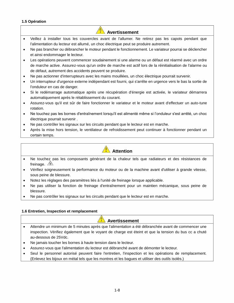
1.5 Opération
Avertissement
Veillez à installer tous les couvercles avant de l'allumer. Ne retirez pas les capots pendant que
l'alimentation du lecteur est allumé, un choc électrique peut se produire autrement.
Ne pas brancher ou débrancher le moteur pendant le fonctionnement. Le variateur pourrai se déclencher
et ainsi endommager le lecteur.
Les opérations peuvent commencer soudainement si une alarme ou un défaut est réarmé avec un ordre
de marche active. Assurez-vous qu'un ordre de marche est actif lors de la réinitialisation de l'alarme ou
de défaut, autrement des accidents peuvent se produire.
Ne pas actionner d'interrupteurs avec les mains mouillées, un choc électrique pourrait survenir.
Un interrupteur d'urgence externe indépendant est fourni, qui s'arrête en urgence vers le bas la sortie de
l'onduleur en cas de danger.
Si le redémarrage automatique après une récupération d'énergie est activée, le variateur démarrera
automatiquement après le rétablissement du courant.
Assurez-vous qu'il est sûr de faire fonctionner le variateur et le moteur avant d'effectuer un auto-tune
rotation.
Ne touchez pas les bornes d'entraînement lorsqu'il est alimenté même si l’onduleur s'est arrêté, un choc
électrique pourrait survenir .
Ne pas contrôler les signaux sur les circuits pendant que le lecteur est en marche.
Après la mise hors tension, le ventilateur de refroidissement peut continuer à fonctionner pendant un
certain temps.
Attention
Ne touchez pas les composants générant de la chaleur tels que radiateurs et des résistances de
freinage.
Vérifiez soigneusement la performance du moteur ou de la machine avant d'utiliser à grande vitesse,
sous peine de blessure.
Notez les réglages des paramètres liés à l'unité de freinage lorsque applicable.
Ne pas utiliser la fonction de freinage d'entraînement pour un maintien mécanique, sous peine de
blessure.
Ne pas contrôler les signaux sur les circuits pendant que le lecteur est en marche.
1.6 Entretien, Inspection et remplacement
Avertissement
Attendre un minimum de 5 minutes après que l'alimentation a été débranchée avant de commencer une
inspection. Vérifiez également que le voyant de charge est éteint et que la tension du bus cc a chuté
au-dessous de 25Vdc.
Ne jamais toucher les bornes à haute tension dans le lecteur.
Assurez-vous que l'alimentation du lecteur est débranché avant de démonter le lecteur.
Seul le personnel autorisé peuvent faire l'entretien, l'inspection et les opérations de remplacement.
(Enlevez les bijoux en métal tels que les montres et les bagues et utiliser des outils isolés.)
1-9
Attention
Le variateur peut être utilisé dans un environnement avec une gamme de température allant de
14 ° -104 ° F (10-40 ° C) et l'humidité relative de 95% sans condensation.
Le variateur doit être utilisé dans un environnement sans poussière, gaz, vapeur et humidité.
1.7 Mise au rebut du variateur
Attention
jeter cet appareil avec soin comme un déchet industriel et selon les réglementations locales nécessaires.
Les condensateurs du circuit principal d'entraînement et circuits imprimés sont considérés comme des
déchets dangereux et ne doivent pas être brûlés.
The Plastic enclosure and parts of the drive such as the top cover board will release harmful gases if
burned.
2-1
2. Model Description
2.1 Nameplate Data
It is essential to verify the E510 inverter nameplate and make sure that the E510 inverter has the correct rating so
it can be used in your application with the proper sized AC motor.
Unpack the E510 inverter and check the following:
(1) The E510 inverter and start-up and installation manual (this document) are contained in the package.
(2) The E510 inverter has not been damaged during transportation there should be no dents or parts missing.
(3) The E510 inverter is the type you ordered. You can check the type and specifications on the main nameplate.
(4) Check that the input voltage range meets the input power requirements.
(5) Ensure that the motor HP matches the motor rating of the inverter.
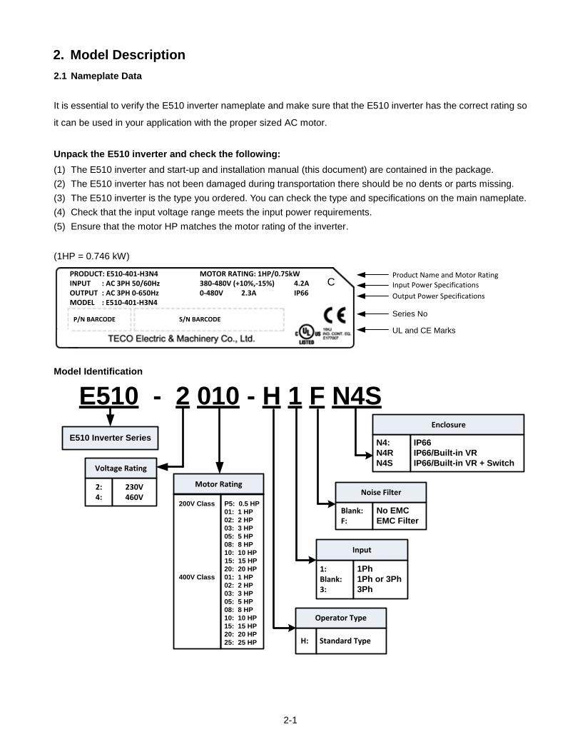
(1HP = 0.746 kW)
Product Name and Motor RatingInput Power Specifications
Output Power Specifications
Series No
UL and CE Marks
PRODUCT: E510-401-H3N4 MOTOR RATING: 1HP/0.75kWINPUT : AC 3PH 50/60Hz 380-480V (+10%,-15%) 4.2AOUTPUT : AC 3PH 0-650Hz 0-480V 2.3A IP66MODEL : E510-401-H3N4
P/N BARCODE S/N BARCODE
C
Model Identification
E510 Inverter Series
E510 - 2 010 - H 1 F N4S
2:4:
230V460V
Voltage Rating
Motor Rating
H: Standard Type
Operator Type
1: Blank:3:
1Ph
1Ph or 3Ph
3Ph
Input
Blank: F:
No EMC
EMC Filter
Noise Filter
200V Class P5: 0.5 HP
01: 1 HP
02: 2 HP
03: 3 HP
05: 5 HP
08: 8 HP
10: 10 HP
15: 15 HP
20: 20 HP
400V Class 01: 1 HP
02: 2 HP
03: 3 HP
05: 5 HP
08: 8 HP
10: 10 HP
15: 15 HP
20: 20 HP
25: 25 HP
N4:
N4R
N4S
IP66
IP66/Built-in VR
IP66/Built-in VR + Switch
Enclosure
2-2
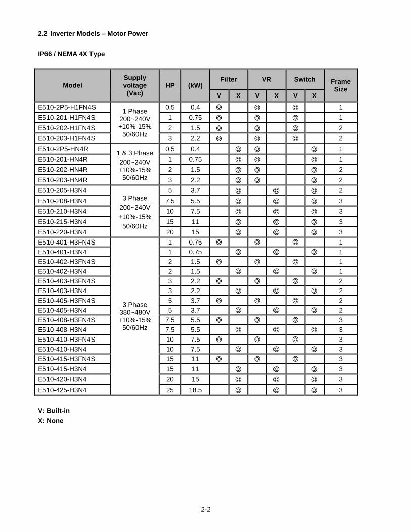
2.2 Inverter Models – Motor Power
IP66 / NEMA 4X Type
Model Supply voltage (Vac)
HP (kW) Filter VR Switch Frame
Size V X V X V X
E510-2P5-H1FN4S 1 Phase
200~240V +10%-15%
50/60Hz
0.5 0.4 1
E510-201-H1FN4S 1 0.75 1
E510-202-H1FN4S 2 1.5 2
E510-203-H1FN4S 3 2.2 2
E510-2P5-HN4R 1 & 3 Phase
200~240V +10%-15%
50/60Hz
0.5 0.4 1
E510-201-HN4R 1 0.75 1
E510-202-HN4R 2 1.5 2
E510-203-HN4R 3 2.2 2
E510-205-H3N4 3 Phase
200~240V
+10%-15%
50/60Hz
5 3.7 2
E510-208-H3N4 7.5 5.5 3
E510-210-H3N4 10 7.5 3
E510-215-H3N4 15 11 3
E510-220-H3N4 20 15 3
E510-401-H3FN4S
3 Phase 380~480V +10%-15%
50/60Hz
1 0.75 1
E510-401-H3N4 1 0.75 1
E510-402-H3FN4S 2 1.5 1
E510-402-H3N4 2 1.5 1
E510-403-H3FN4S 3 2.2 2
E510-403-H3N4 3 2.2 2
E510-405-H3FN4S 5 3.7 2
E510-405-H3N4 5 3.7 2
E510-408-H3FN4S 7.5 5.5 3
E510-408-H3N4 7.5 5.5 3
E510-410-H3FN4S 10 7.5 3
E510-410-H3N4 10 7.5 3
E510-415-H3FN4S 15 11 3
E510-415-H3N4 15 11 3
E510-420-H3N4 20 15 3
E510-425-H3N4 25 18.5 3
V: Built-in
X: None
3-1
3. Environment and Installation
3.1 Environment
The environment will directly affect the proper operation and the life span of the inverter. To ensure
that the inverter will give maximum service life, please comply with the following environmental
conditions:
Protection
Protection Class IP66 / NEMA 4X (Depending on models)
Operating
Temperature
IP66 / NEMA 4X type: -10°C - +50°C (14-122 °F)
If several inverters are placed in the same control panel, provide a heat
removal means to maintain ambient temperatures below 40°C
Storage
Temperature -20°C - +60°C (-4 -140 °F)
Humidity: 95% non-condensing
Relative humidity 5% to 95%, free of moisture.
(Follow IEC60068-2-78 standard)
Altitude: < 1000m (3,281 ft.)
Installation Site: Avoid exposure to rain or moisture.
Avoid direct sunlight.
Avoid oil mist and salinity.
Avoid corrosive liquid and gas.
Avoid dust, lint fibers, and small metal filings.
Keep away from radioactive and flammable materials.
Avoid electromagnetic interference (soldering machines, power machines).
Avoid vibration (stamping, punching machines etc.).
Add a vibration-proof pad if the situation cannot be avoided.
Shock Maximum acceleration: 1G (9.8m/s²), for <20Hz
Maximum acceleration: 0.6G (5.88m/s²), for 20 - 50Hz (IEC60068-2-6 standard)
3-2
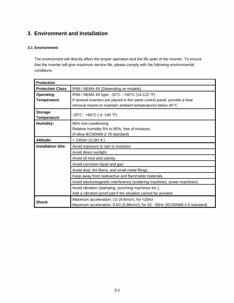
3.2 Warning Labels
Important: Warning information located on the front cover must be read upon installation of the inverter.
3-3
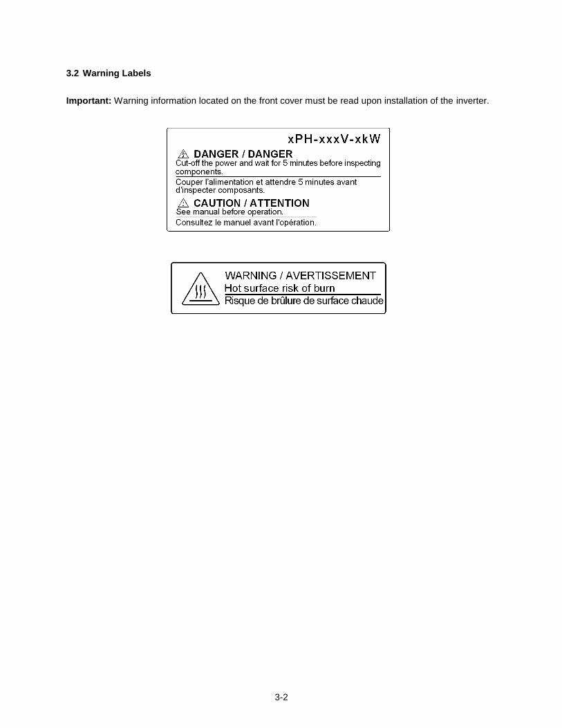
3.3 Removing the Front Cover and Keypad
Caution
Before making any wiring connections to the inverter the front cover needs to be removed.
IP66 / NEMA 4X
Step 1: Unscrew cover and place cover next to the inverter
3-4
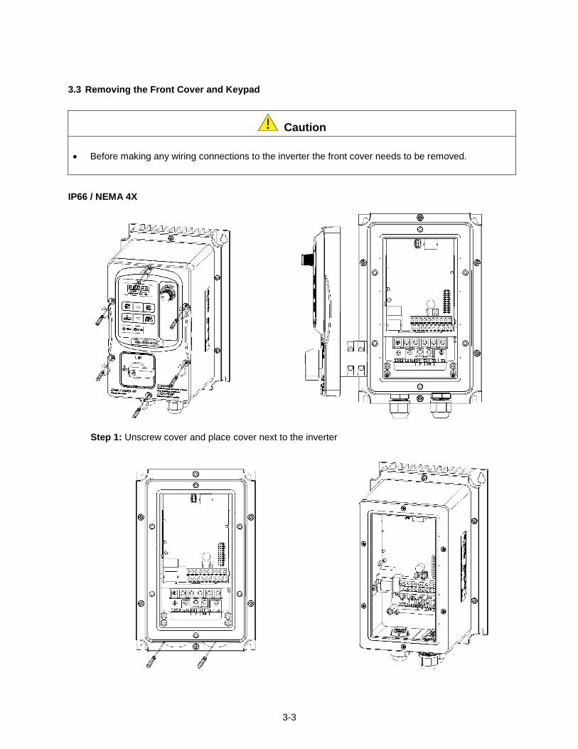
Step 2: Remove the rubber plugs and use the waterproof cable glands provided to connect cables.
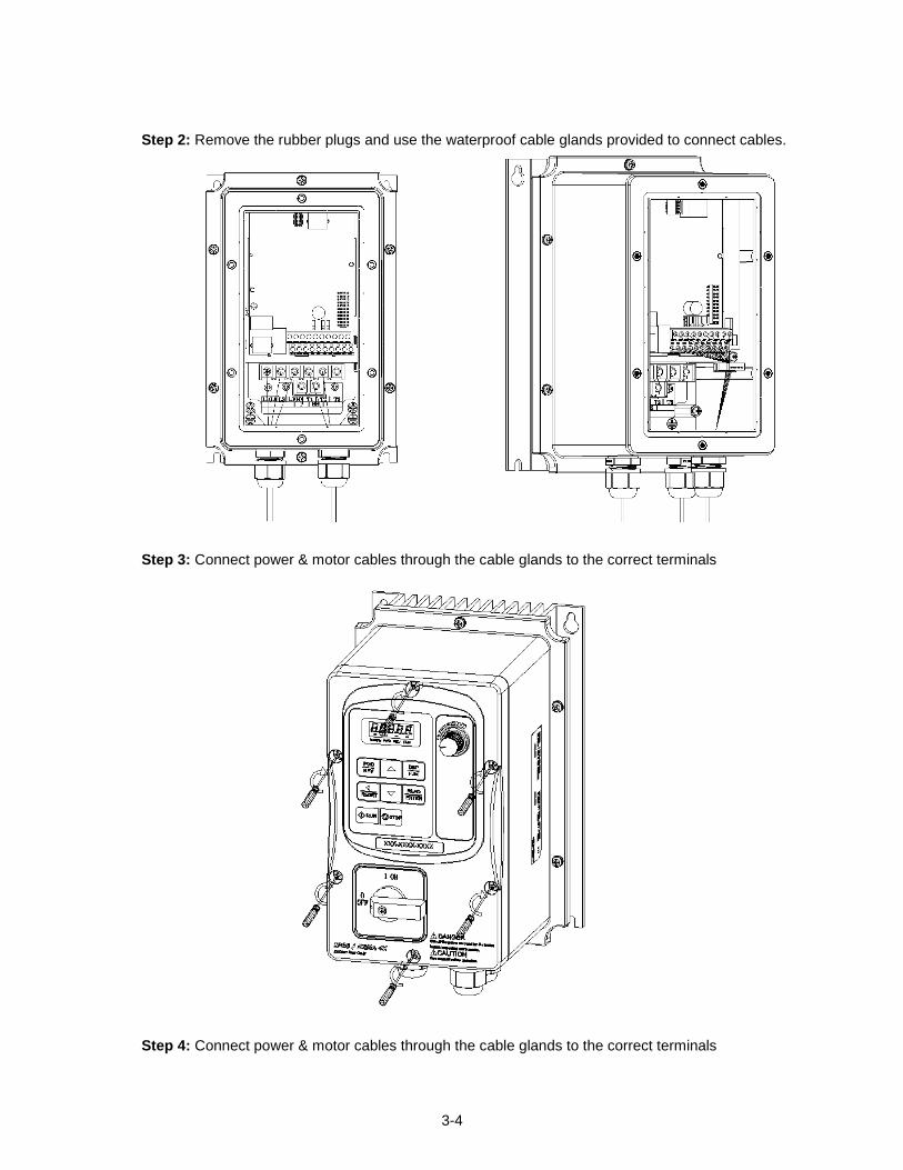
Step 3: Connect power & motor cables through the cable glands to the correct terminals
Step 4: Connect power & motor cables through the cable glands to the correct terminals
3-5
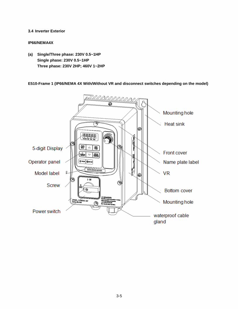
3.4 Inverter Exterior
IP66/NEMA4X
(a) Single/Three phase: 230V 0.5~1HP
Single phase: 230V 0.5~1HP
Three phase: 230V 2HP; 460V 1~2HP
E510-Frame 1 (IP66/NEMA 4X With/Without VR and disconnect switches depending on the model)
3-6
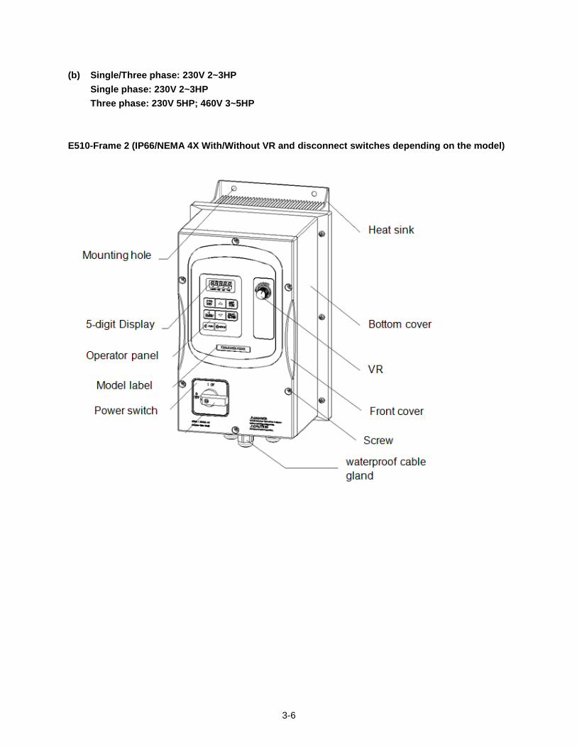
(b) Single/Three phase: 230V 2~3HP
Single phase: 230V 2~3HP
Three phase: 230V 5HP; 460V 3~5HP
E510-Frame 2 (IP66/NEMA 4X With/Without VR and disconnect switches depending on the model)
3-7
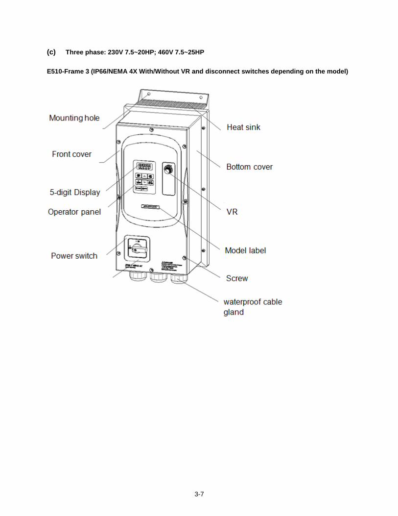
(c) Three phase: 230V 7.5~20HP; 460V 7.5~25HP
E510-Frame 3 (IP66/NEMA 4X With/Without VR and disconnect switches depending on the model)
3-8
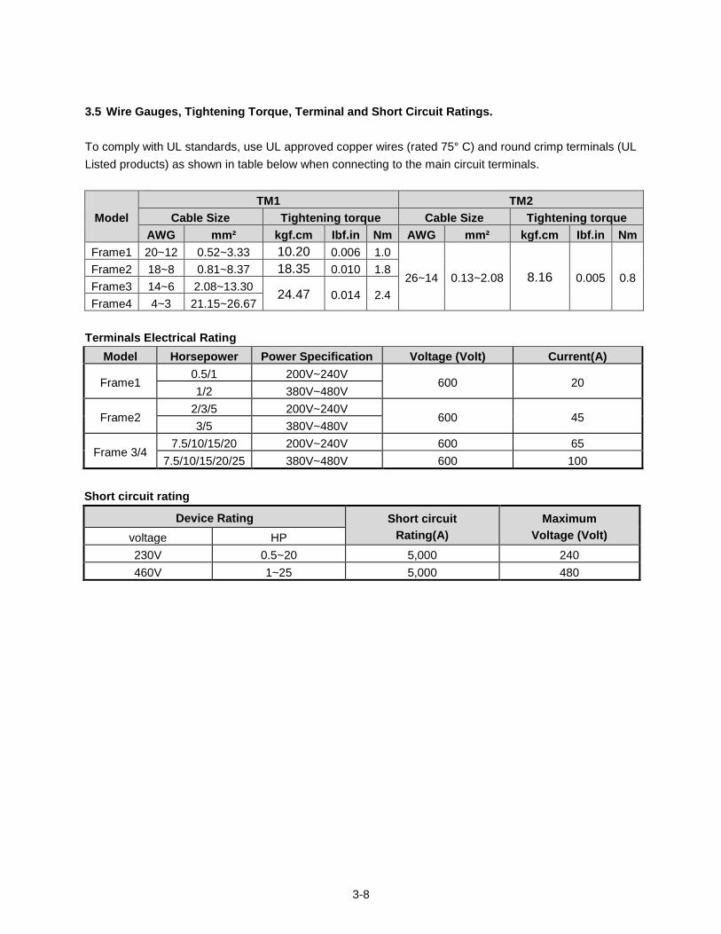
3.5 Wire Gauges, Tightening Torque, Terminal and Short Circuit Ratings.
To comply with UL standards, use UL approved copper wires (rated 75° C) and round crimp terminals (UL
Listed products) as shown in table below when connecting to the main circuit terminals.
Model
TM1 TM2
Cable Size Tightening torque Cable Size Tightening torque
AWG mm² kgf.cm Ibf.in Nm AWG mm² kgf.cm Ibf.in Nm
Frame1 20~12 0.52~3.33 10.20 0.006 1.0
26~14 0.13~2.08 8.16 0.005 0.8 Frame2 18~8 0.81~8.37 18.35 0.010 1.8
Frame3 14~6 2.08~13.30 24.47 0.014 2.4
Frame4 4~3 21.15~26.67
Terminals Electrical Rating
Model Horsepower Power Specification Voltage (Volt) Current(A)
Frame1 0.5/1 200V~240V
600 20 1/2 380V~480V
Frame2 2/3/5 200V~240V
600 45 3/5 380V~480V
Frame 3/4 7.5/10/15/20 200V~240V 600 65
7.5/10/15/20/25 380V~480V 600 100
Short circuit rating
Device Rating Short circuit
Rating(A)
Maximum
Voltage (Volt) voltage HP
230V 0.5~20 5,000 240
460V 1~25 5,000 480
3-9
3.6 Wiring Peripheral Power Devices
Caution
After power is shut off to the inverter the capacitors will slowly discharge. Do NOT touch and of the inverter circuitry or replace any components until the “CHARGE” indicator is off.
Do NOT wire or connect/disconnect internal connectors of the inverter when the inverter is powered up or when powered off and the “CHARGE”” indicator is on.
Do NOT connect inverter output U, V and W to the supply power. This will result in damage to the inverter.
The inverter must by properly grounded. Use terminal E to connect earth ground and comply with
local standards.
Do NOT perform a dielectric voltage withstand test (Megger) on the inverter this will result in inverter
damage to the semiconductor components.
Do NOT touch any of the components on the inverter control board to prevent damage to the inverter
by static electricity.
Caution
Refer to the recommended wire size table for the appropriate wire to use. The voltage between the power supply and the input of the inverter may not exceed 2%.
Phase-to-phase voltage drop (V) = 3 ×resistance of wire (Ω/km) × length of line m) × current×10-3
.
(km=3280 x feet) / (m=3.28 x feet )
Reduce the carrier frequency (parameter 11-01) If the cable from the inverter to the motor is greater than 25m (82ft). A high-frequency current can be generated by stray capacitance between the cables and result in an overcurrent trip of the inverter, an increase in leakage current, or an inaccurate current readout.
To protect peripheral equipment, install fast acting fuses on the input side of the inverter. Refer to
section 11.6 for additional information.
3-10
~~~Power Supply
MCCB
Molded
Circuit
Breaker
Magnetic
Contactor
AC
Reactor
Fast
Acting
Fuse
Input Noise
Filter
E510
Inverter
Ground
Induction
Motor
Ground
Output Noise
Filter
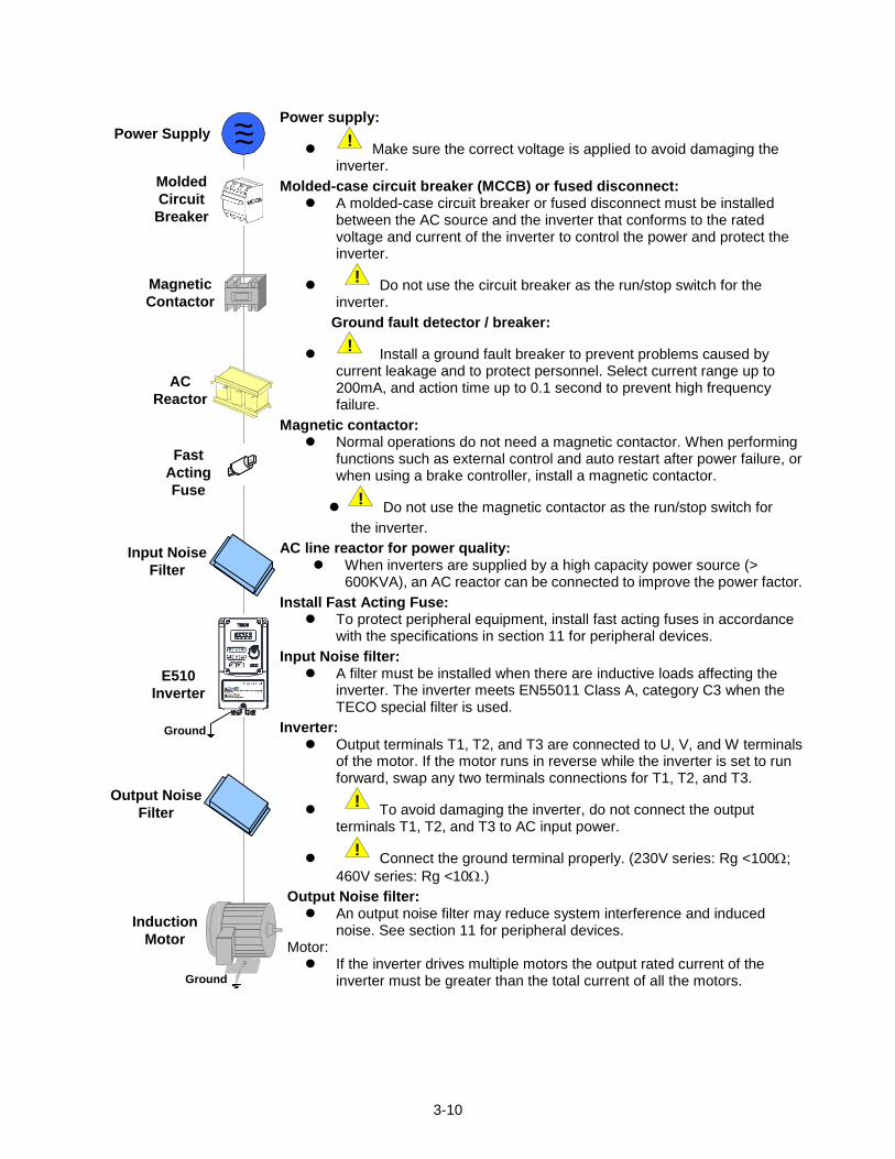
Power supply:
!
Make sure the correct voltage is applied to avoid damaging the inverter.
Molded-case circuit breaker (MCCB) or fused disconnect: A molded-case circuit breaker or fused disconnect must be installed
between the AC source and the inverter that conforms to the rated voltage and current of the inverter to control the power and protect the inverter.
!
Do not use the circuit breaker as the run/stop switch for the inverter.
Ground fault detector / breaker:
!
Install a ground fault breaker to prevent problems caused by current leakage and to protect personnel. Select current range up to 200mA, and action time up to 0.1 second to prevent high frequency failure.
Magnetic contactor: Normal operations do not need a magnetic contactor. When performing
functions such as external control and auto restart after power failure, or when using a brake controller, install a magnetic contactor.
!
Do not use the magnetic contactor as the run/stop switch for
the inverter.
AC line reactor for power quality: When inverters are supplied by a high capacity power source (>
600KVA), an AC reactor can be connected to improve the power factor.
Install Fast Acting Fuse: To protect peripheral equipment, install fast acting fuses in accordance
with the specifications in section 11 for peripheral devices.
Input Noise filter: A filter must be installed when there are inductive loads affecting the
inverter. The inverter meets EN55011 Class A, category C3 when the TECO special filter is used.
Inverter: Output terminals T1, T2, and T3 are connected to U, V, and W terminals
of the motor. If the motor runs in reverse while the inverter is set to run forward, swap any two terminals connections for T1, T2, and T3.
!
To avoid damaging the inverter, do not connect the output terminals T1, T2, and T3 to AC input power.
!
Connect the ground terminal properly. (230V series: Rg <100;
460V series: Rg <10.)
Output Noise filter: An output noise filter may reduce system interference and induced
noise. See section 11 for peripheral devices. Motor:
If the inverter drives multiple motors the output rated current of the inverter must be greater than the total current of all the motors.
3-11
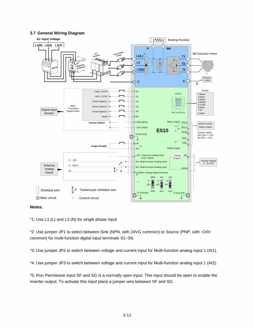
3.7 General Wiring Diagram
L1(L)
L2
L3(N)
T1
T2
T3
P BR
3Ø Induction motor
E
+10V: Power for Analog Input
(max. 20mA)
AI1: Multi-Function Analog Input
AI2: Multi-Function Analog Input
S1
External
Analog
Inputs
Digital Input
Section
+
-
Ground
< 100Ω
Analog
Output 1
AO
AGND
Analog Outputs
0 – 10 VDC
S2
S3
S4
S5
E510
Multi-
Functional
Digital Inputs Preset Speed 3
Preset Speed 2
Preset Speed 1
FWD / STOP
REV / STOP
Factory Default
L1(R) L2(S) L3(T)
Magnetic
ContactorMCCB
AC
Reactor
Fast Acting
Fuses
AC Input Voltage Braking Resistor
COM (NPN)
AGND: Analog Signal Common0V
0 ~ 20mA
0 ~ 10V
P
P
(R1A)
(R1C)
(R1B)NC
NO
Multi-Function
Relay Output
Contact rating:
250 VAC < 1.0A
30 VDC < 1.0AR2A
R2B
*2
S6Reset
+24V (PNP)
E (Ground)
E (Ground) E (Ground)
NO
Relay Output
Relay Output
SF
SG
E
Output Disable
NPN
PNP
JP1
AI1
AV1
JP2
AI2
AV2
JP3
*3 *4
*5
*1
RS485
CON 2
Pin 1 to Pin 8
1:Data+
2:Data-
3:Data+
4:RXD0
5:TXD0
6:Data-
7:5V
8:GND
Twisted-pair shielded wire P Shielded wire
Control circuitMain circuit
Notes:
*1: Use L1 (L) and L3 (N) for single phase input
*2: Use jumper JP1 to select between Sink (NPN, with 24VG common) or Source (PNP, with +24V
common) for multi-function digital input terminals S1~S6.
*3: Use jumper JP2 to switch between voltage and current input for Multi-function analog input 1 (AI1).
*4: Use jumper JP3 to switch between voltage and current input for Multi-function analog input 1 (AI2).
*5: Run Permissive input SF and SG is a normally open input. This input should be open to enable the
inverter output. To activate this input place a jumper wire between SF and SG.
3-12
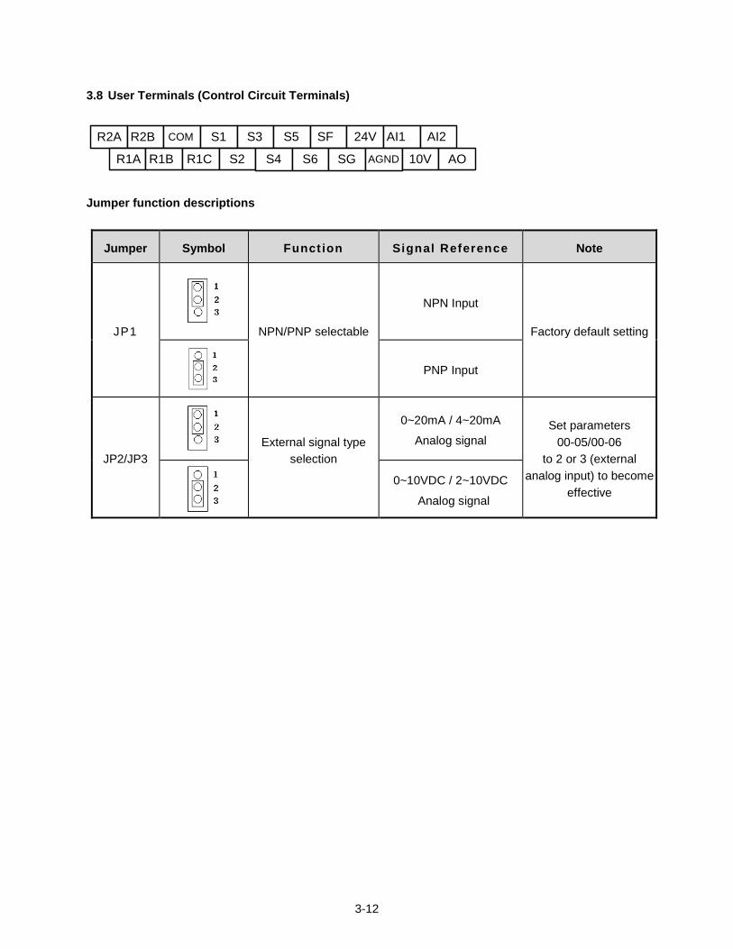
3.8 User Terminals (Control Circuit Terminals)
R2A R2B COM S1 S3 S5 SF 24V AI1 AI2
R1A R1B R1C S2 S4 S6 SG AGND 10V AO
Jumper function descriptions
Jumper Symbol Funct ion Signal Reference Note
JP1 NPN/PNP selectable
NPN Input
Factory default setting
PNP Input
JP2/JP3 External signal type
selection
0~20mA / 4~20mA
Analog signal
Set parameters
00-05/00-06
to 2 or 3 (external
analog input) to become
effective
0~10VDC / 2~10VDC
Analog signal
3-13
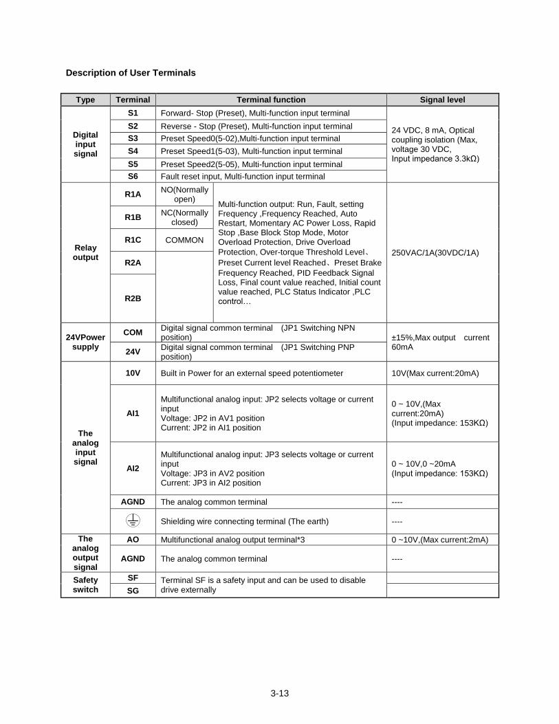
Description of User Terminals
Type Terminal Terminal function Signal level
Digital input signal
S1 Forward- Stop (Preset), Multi-function input terminal
24 VDC, 8 mA, Optical coupling isolation (Max, voltage 30 VDC, Input impedance 3.3kΩ)
S2 Reverse - Stop (Preset), Multi-function input terminal
S3 Preset Speed0(5-02),Multi-function input terminal
S4 Preset Speed1(5-03), Multi-function input terminal
S5 Preset Speed2(5-05), Multi-function input terminal
S6 Fault reset input, Multi-function input terminal
Relay output
R1A NO(Normally
open) Multi-function output: Run, Fault, setting Frequency ,Frequency Reached, Auto Restart, Momentary AC Power Loss, Rapid Stop ,Base Block Stop Mode, Motor Overload Protection, Drive Overload
Protection, Over-torque Threshold Level、
Preset Current level Reached、Preset Brake
Frequency Reached, PID Feedback Signal Loss, Final count value reached, Initial count value reached, PLC Status Indicator ,PLC control…
250VAC/1A(30VDC/1A)
R1B NC(Normally
closed)
R1C COMMON
R2A
R2B
24VPower supply
COM Digital signal common terminal (JP1 Switching NPN position) ±15%,Max output current
60mA 24V
Digital signal common terminal (JP1 Switching PNP position)
The analog input signal
10V Built in Power for an external speed potentiometer 10V(Max current:20mA)
AI1
Multifunctional analog input: JP2 selects voltage or current input Voltage: JP2 in AV1 position Current: JP2 in AI1 position
0 ~ 10V,(Max current:20mA) (Input impedance: 153KΩ)
AI2
Multifunctional analog input: JP3 selects voltage or current input Voltage: JP3 in AV2 position Current: JP3 in AI2 position
0 ~ 10V,0 ~20mA (Input impedance: 153KΩ)
AGND The analog common terminal ----
Shielding wire connecting terminal (The earth) ----
The analog output signal
AO Multifunctional analog output terminal*3 0 ~10V,(Max current:2mA)
AGND The analog common terminal ----
Safety switch
SF Terminal SF is a safety input and can be used to disable drive externally
SG
3-14
Notes:
*1:Multi-function digital input can be referred to in this manual.
- Group 03: External Terminals Digital Input / Output Function Group.
*2:Multi-function analog input can be referred to in this manual..
- Group 04 - External Terminal Analog Signal Input (Output) Function Group.
*3:Multi-function analog output can be referred to in this manual.
- Group 04 - External Terminal Analog Signal Input (Output) Function Group.
Caution
Maximum output current capacity for terminal 12V is 20mA.
Multi-function analog output AO1 and AO2 are for use for an analog output meter. Do not use these output for feedback control.
Control board’s 24V and ±12V are to be used for internal control only, Do not use the internal power-supply to power external devices.
3-15
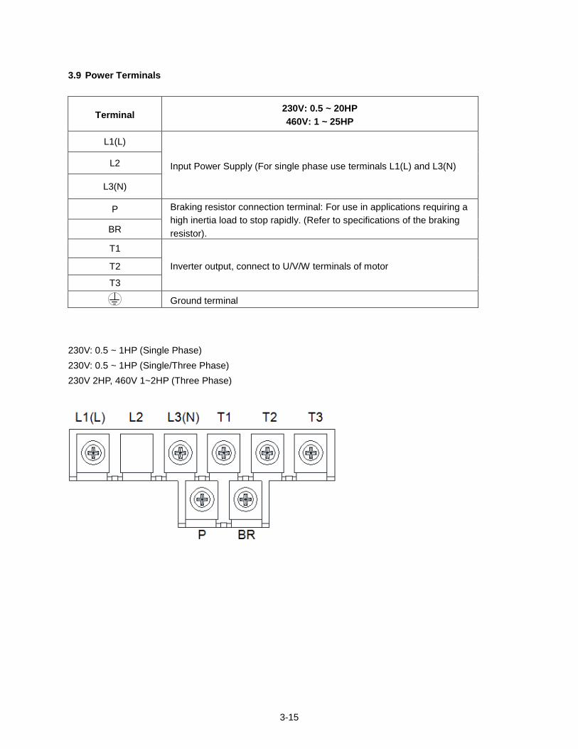
3.9 Power Terminals
Terminal 230V: 0.5 ~ 20HP
460V: 1 ~ 25HP
L1(L)
Input Power Supply (For single phase use terminals L1(L) and L3(N) L2
L3(N)
P Braking resistor connection terminal: For use in applications requiring a
high inertia load to stop rapidly. (Refer to specifications of the braking
resistor). BR
T1
Inverter output, connect to U/V/W terminals of motor T2
T3
Ground terminal
230V: 0.5 ~ 1HP (Single Phase)
230V: 0.5 ~ 1HP (Single/Three Phase)
230V 2HP, 460V 1~2HP (Three Phase)
3-16
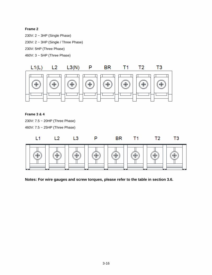
Frame 2
230V: 2 ~ 3HP (Single Phase)
230V: 2 ~ 3HP (Single / Three Phase)
230V: 5HP (Three Phase)
460V: 3 ~ 5HP (Three Phase)
Frame 3 & 4
230V: 7.5 ~ 20HP (Three Phase)
460V: 7.5 ~ 25HP (Three Phase)
Notes: For wire gauges and screw torques, please refer to the table in section 3.6.
3-17
3.10 Inverter Wiring
Wiring Precautions
Danger!
Do NOT remove any protective covers or attempt any wiring while input power is applied. Connect all wiring before applying input power. When making wiring changes after power up, remove input power and wait a minimum of five minutes after power has been turned off before starting. Also confirm that the charge lamp is off and that DC voltage between terminals B1/P or (+) and (-) does not exceed 25V, otherwise electric shock may result.
Only authorized personnel should work on the equipment. (Take off metal jewelry such as watches and rings and use insulated tools.), otherwise electric shock or injury may result.
(A) Power input terminals
1. The Input power supply voltage can be connected in any phase sequence to power input terminals
R/L1, S/L2, or T/L3 on the terminal block.
2. DO NOT connect the AC input power source to the output terminals U/T1, V/T2 and. W/T3.
3. Connect the output terminals U/T1, V/T2, W/T3 to motor lead wires U/T1, V/T2, and W/T3,
respectively.
4. Check that the motor rotates forward with the forward run source. If it does not, swap any 2 of the
output cables to change motor direction.
5. DO NOT connect phase correcting capacitors or LC/RC noise filter to the output circuit.
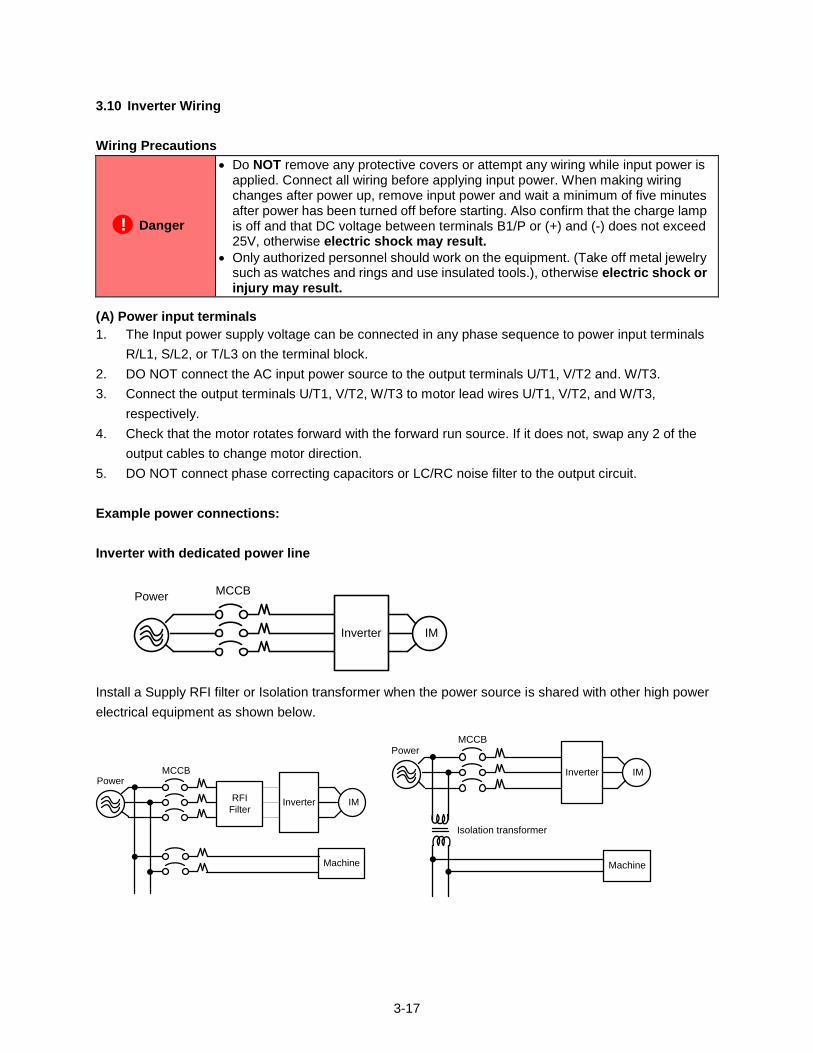
Example power connections:
Inverter with dedicated power line
Inverter IM
Power MCCB
Install a Supply RFI filter or Isolation transformer when the power source is shared with other high power
electrical equipment as shown below.
Inverter IM
Machine
RFI
Filter
Power MCCB
Inverter IM
Machine
Isolation transformer
Power MCCB
3-18
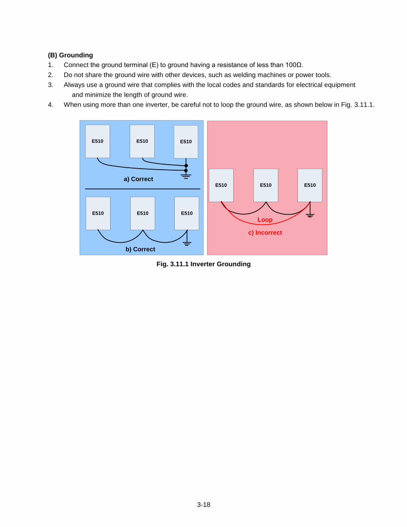
(B) Grounding
1. Connect the ground terminal (E) to ground having a resistance of less than 100Ω.
2. Do not share the ground wire with other devices, such as welding machines or power tools.
3. Always use a ground wire that complies with the local codes and standards for electrical equipment
and minimize the length of ground wire.
4. When using more than one inverter, be careful not to loop the ground wire, as shown below in Fig. 3.11.1.
E510 E510 E510
E510 E510 E510
a) Correct
b) Correct
E510 E510 E510
c) Incorrect
Loop
Fig. 3.11.1 Inverter Grounding
3-19
3.11 Input Power and Motor Cable Length
The length of the cables between the input power source and /or the motor and inverter can cause a
significant phase to phase voltage reduction due to the voltage drop across the cables. The wire size
shown in Tables 3.16.1 is based on a maximum voltage drop of 2%. If this value is exceeded, a wire size
having larger diameter may be needed. To calculate phase tot phase voltage drop, apply the following
formula:
Phase-to-phase voltage drop (V) = 3 ×resistance of wire (Ω/km) × length of line m) × current×10-3
.
(km=3280 x feet)
(m=3.28 x feet )
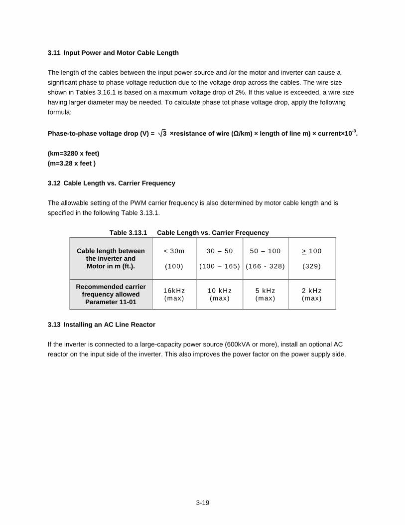
3.12 Cable Length vs. Carrier Frequency
The allowable setting of the PWM carrier frequency is also determined by motor cable length and is
specified in the following Table 3.13.1.
Table 3.13.1 Cable Length vs. Carrier Frequency
Cable length between the inverter and Motor in m (ft.).
< 30m
(100)
30 – 50
(100 – 165)
50 – 100
(166 - 328)
> 100
(329)
Recommended carrier frequency allowed Parameter 11-01
16kHz (max)
10 kHz (max)
5 kHz (max)
2 kHz (max)
3.13 Installing an AC Line Reactor
If the inverter is connected to a large-capacity power source (600kVA or more), install an optional AC
reactor on the input side of the inverter. This also improves the power factor on the power supply side.
3-20
3.14 Power Input Wire Size, and NFB
The following table shows the recommended wire size for each frame of the E510. It depends on the
application whether or not to install a circuit breaker. The NFB must be installed between the input power
supply and the inverter input (L1 (L), L2, L3 (N)).
Note: When using a ground protection make sure the current setting is above 200mA and trip delay time is
0.1 sec of higher.
Table 3.16.1 Wiring instrument for frame 1 ~ 4
Model
TM1 TM2
Cable Size Tightening torque Cable Size Tightening torque
AWG mm² kgf.cm Ibf.in Nm AWG mm² kgf.cm Ibf.in Nm
Frame1 20~12 0.52~3.33 10.20 0.006 1.0
26~14 0.13~2.08 8.16 0.005 0.8 Frame2 18~8 0.81~8.37 18.35 0.010 1.8
Frame3 14~6 2.08~13.30 24.47 0.014 2.4
Frame4 4~3 21.15~26.67
3.15 Control Circuit Wiring
(1) Separate the wiring for control circuit terminals from main circuit wiring for terminals (R/L1, S/L2,
T/L3, U/T1, V/T2, W/T3).
(2) Separate the wiring for control circuit terminals R1A-R1B-R1C or R2A, R2B (Relay outputs) from wiring for terminals S1 – S6, A0, AGND, +10V, AI1, AI2 and GND wiring.
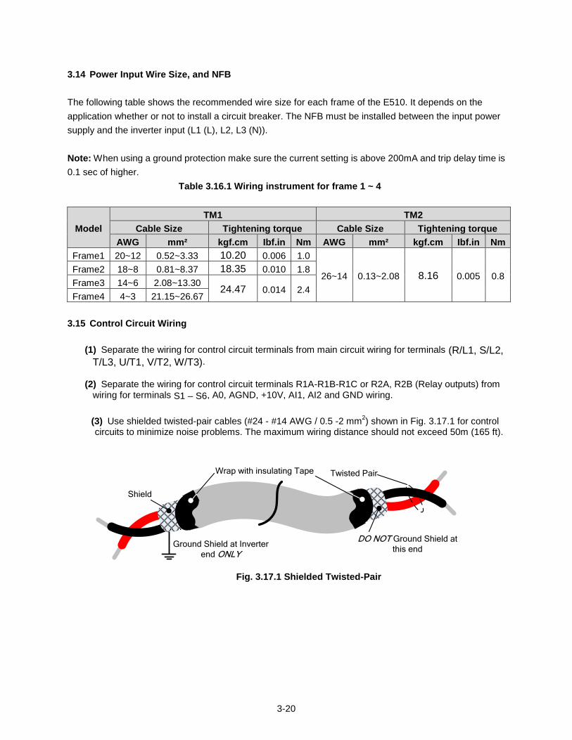
(3) Use shielded twisted-pair cables (#24 - #14 AWG / 0.5 -2 mm2) shown in Fig. 3.17.1 for control
circuits to minimize noise problems. The maximum wiring distance should not exceed 50m (165 ft).
Shield
Twisted PairWrap with insulating Tape
Ground Shield at Inverter
end ONLY
DO NOT Ground Shield at
this end
Fig. 3.17.1 Shielded Twisted-Pair
3-21
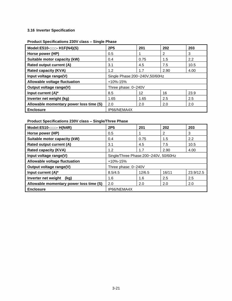
3.16 Inverter Specification
Product Specifications 230V class – Single Phase
Model:E510-- H1F(N4)(S) 2P5 201 202 203
Horse power (HP) 0.5 1 2 3
Suitable motor capacity (kW) 0.4 0.75 1.5 2.2
Rated output current (A) 3.1 4.5 7.5 10.5
Rated capacity (KVA) 1.2 1.7 2.90 4.00
Input voltage range(V) Single Phase:200~240V,50/60Hz
Allowable voltage fluctuation +10%-15%
Output voltage range(V) Three phase: 0~240V
Input current (A)* 8.5 12 16 23.9
Inverter net weight (kg) 1.65 1.65 2.5 2.5
Allowable momentary power loss time (S) 2.0 2.0 2.0 2.0
Enclosure IP66/NEMA4X
Product Specifications 230V class – Single/Three Phase
Model:E510-- H(N4R) 2P5 201 202 203
Horse power (HP) 0.5 1 2 3
Suitable motor capacity (kW) 0.4 0.75 1.5 2.2
Rated output current (A) 3.1 4.5 7.5 10.5
Rated capacity (KVA) 1.2 1.7 2.90 4.00
Input voltage range(V) Single/Three Phase:200~240V, 50/60Hz
Allowable voltage fluctuation +10%-15%
Output voltage range(V) Three phase: 0~240V
Input current (A)* 8.5/4.5 12/6.5 16/11 23.9/12.5
Inverter net weight (kg) 1.6 1.6 2.5 2.5
Allowable momentary power loss time (S) 2.0 2.0 2.0 2.0
Enclosure IP66/NEMA4X
3-22
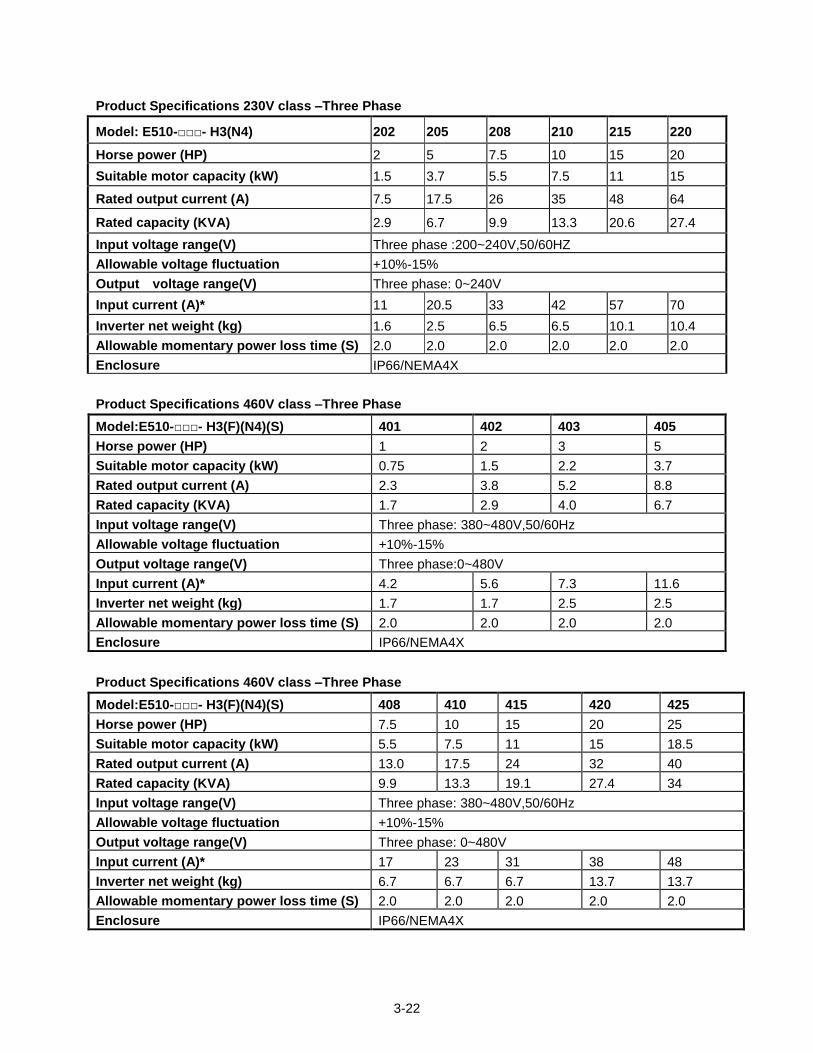
Product Specifications 230V class –Three Phase
Model: E510-- H3(N4) 202 205 208 210 215 220
Horse power (HP) 2 5 7.5 10 15 20
Suitable motor capacity (kW) 1.5 3.7 5.5 7.5 11 15
Rated output current (A) 7.5 17.5 26 35 48 64
Rated capacity (KVA) 2.9 6.7 9.9 13.3 20.6 27.4
Input voltage range(V) Three phase :200~240V,50/60HZ
Allowable voltage fluctuation +10%-15%
Output voltage range(V) Three phase: 0~240V
Input current (A)* 11 20.5 33 42 57 70
Inverter net weight (kg) 1.6 2.5 6.5 6.5 10.1 10.4
Allowable momentary power loss time (S) 2.0 2.0 2.0 2.0 2.0 2.0
Enclosure IP66/NEMA4X
Product Specifications 460V class –Three Phase
Model:E510-- H3(F)(N4)(S) 401 402 403 405
Horse power (HP) 1 2 3 5
Suitable motor capacity (kW) 0.75 1.5 2.2 3.7
Rated output current (A) 2.3 3.8 5.2 8.8
Rated capacity (KVA) 1.7 2.9 4.0 6.7
Input voltage range(V) Three phase: 380~480V,50/60Hz
Allowable voltage fluctuation +10%-15%
Output voltage range(V) Three phase:0~480V
Input current (A)* 4.2 5.6 7.3 11.6
Inverter net weight (kg) 1.7 1.7 2.5 2.5
Allowable momentary power loss time (S) 2.0 2.0 2.0 2.0
Enclosure IP66/NEMA4X
Product Specifications 460V class –Three Phase
Model:E510-- H3(F)(N4)(S) 408 410 415 420 425
Horse power (HP) 7.5 10 15 20 25
Suitable motor capacity (kW) 5.5 7.5 11 15 18.5
Rated output current (A) 13.0 17.5 24 32 40
Rated capacity (KVA) 9.9 13.3 19.1 27.4 34
Input voltage range(V) Three phase: 380~480V,50/60Hz
Allowable voltage fluctuation +10%-15%
Output voltage range(V) Three phase: 0~480V
Input current (A)* 17 23 31 38 48
Inverter net weight (kg) 6.7 6.7 6.7 13.7 13.7
Allowable momentary power loss time (S) 2.0 2.0 2.0 2.0 2.0
Enclosure IP66/NEMA4X
3-23
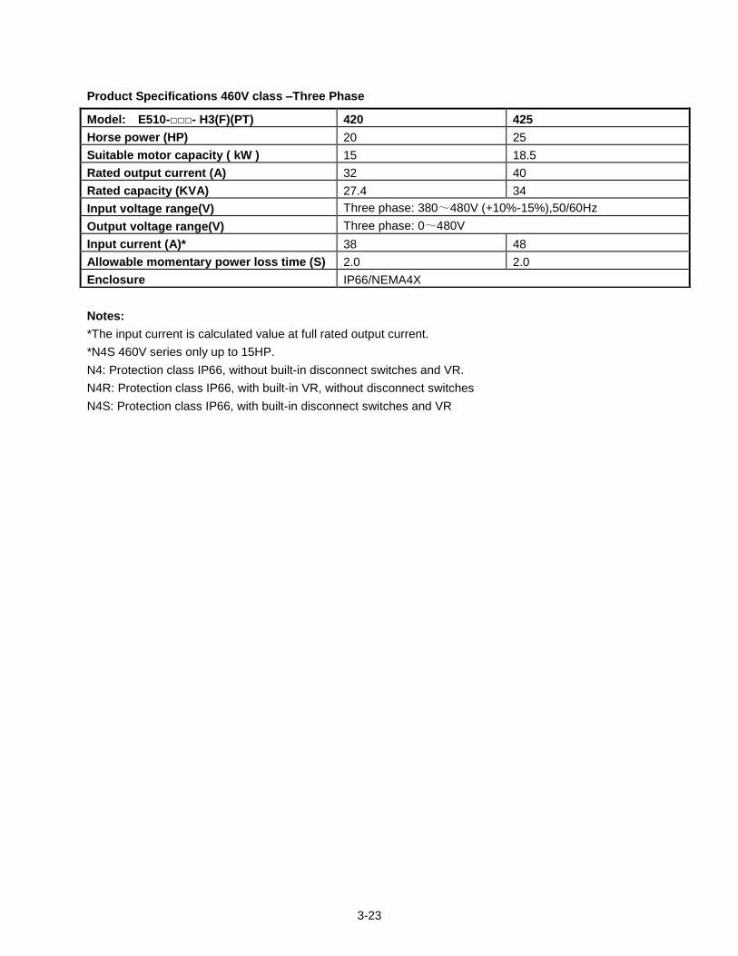
Product Specifications 460V class –Three Phase
Notes:
*The input current is calculated value at full rated output current.
*N4S 460V series only up to 15HP.
N4: Protection class IP66, without built-in disconnect switches and VR.
N4R: Protection class IP66, with built-in VR, without disconnect switches
N4S: Protection class IP66, with built-in disconnect switches and VR
Model: E510-- H3(F)(PT) 420 425
Horse power (HP) 20 25
Suitable motor capacity ( kW ) 15 18.5
Rated output current (A) 32 40
Rated capacity (KVA) 27.4 34
Input voltage range(V) Three phase: 380~480V (+10%-15%),50/60Hz
Output voltage range(V) Three phase: 0~480V
Input current (A)* 38 48
Allowable momentary power loss time (S) 2.0 2.0
Enclosure IP66/NEMA4X
3-24
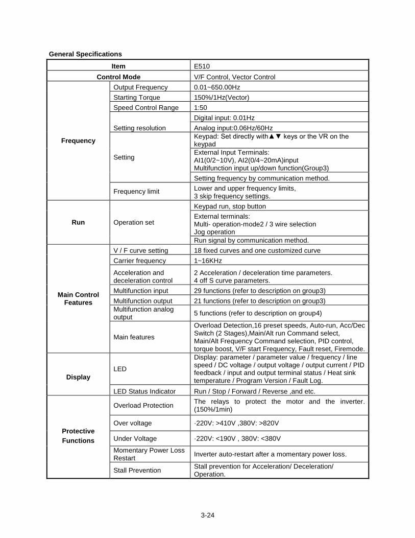
General Specifications
Item E510
Control Mode V/F Control, Vector Control
Frequency
Output Frequency 0.01~650.00Hz
Starting Torque 150%/1Hz(Vector)
Speed Control Range 1:50
Setting resolution
Digital input: 0.01Hz
Analog input:0.06Hz/60Hz
Setting
Keypad: Set directly with keys or the VR on the keypad
External Input Terminals: AI1(0/2~10V), AI2(0/4~20mA)input Multifunction input up/down function(Group3)
Setting frequency by communication method.
Frequency limit Lower and upper frequency limits, 3 skip frequency settings.
Run Operation set
Keypad run, stop button
External terminals: Multi- operation-mode2 / 3 wire selection Jog operation
Run signal by communication method.
Main Control Features
V / F curve setting 18 fixed curves and one customized curve
Carrier frequency 1~16KHz
Acceleration and deceleration control
2 Acceleration / deceleration time parameters. 4 off S curve parameters.
Multifunction input 29 functions (refer to description on group3)
Multifunction output 21 functions (refer to description on group3)
Multifunction analog output
5 functions (refer to description on group4)
Main features
Overload Detection,16 preset speeds, Auto-run, Acc/Dec Switch (2 Stages),Main/Alt run Command select, Main/Alt Frequency Command selection, PID control, torque boost, V/F start Frequency, Fault reset, Firemode.
Display
LED
Display: parameter / parameter value / frequency / line speed / DC voltage / output voltage / output current / PID feedback / input and output terminal status / Heat sink temperature / Program Version / Fault Log.
LED Status Indicator Run / Stop / Forward / Reverse ,and etc.
Protective
Functions
Overload Protection The relays to protect the motor and the inverter. (150%/1min)
Over voltage ·220V: >410V ,380V: >820V
Under Voltage ·220V: <190V , 380V: <380V
Momentary Power Loss Restart
Inverter auto-restart after a momentary power loss.
Stall Prevention Stall prevention for Acceleration/ Deceleration/ Operation.
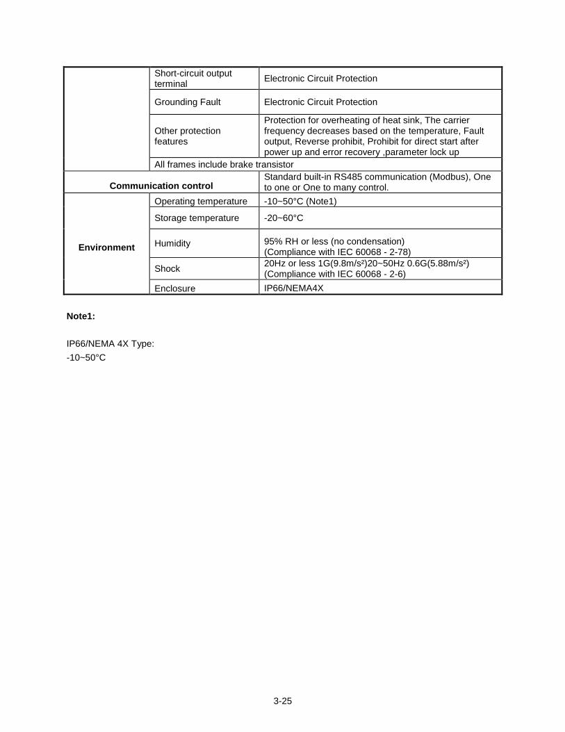
3-25
Short-circuit output terminal
Electronic Circuit Protection
Grounding Fault Electronic Circuit Protection
Other protection features
Protection for overheating of heat sink, The carrier frequency decreases based on the temperature, Fault output, Reverse prohibit, Prohibit for direct start after power up and error recovery ,parameter lock up
All frames include brake transistor
Communication control Standard built-in RS485 communication (Modbus), One to one or One to many control.
Environment
Operating temperature -10~50°C (Note1)
Storage temperature -20~60°C
Humidity 95% RH or less (no condensation) (Compliance with IEC 60068 - 2-78)
Shock 20Hz or less 1G(9.8m/s²)20~50Hz 0.6G(5.88m/s²) (Compliance with IEC 60068 - 2-6)
Enclosure IP66/NEMA4X
Note1:
IP66/NEMA 4X Type:
-10~50°C
3-26
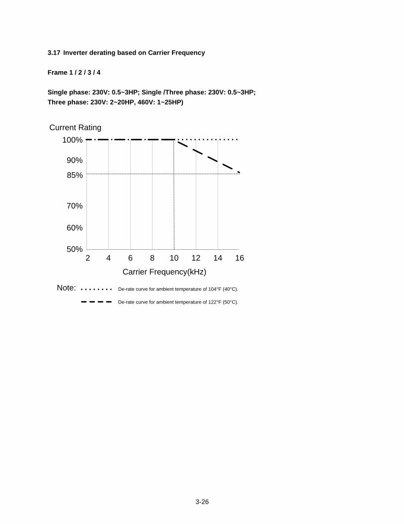
3.17 Inverter derating based on Carrier Frequency
Frame 1 / 2 / 3 / 4
Single phase: 230V: 0.5~3HP; Single /Three phase: 230V: 0.5~3HP;
Three phase: 230V: 2~20HP, 460V: 1~25HP)
100%
70%
85%
90%
50%
60%
2 4 6 8 10 12 14 16
Current Rating
Carrier Frequency(kHz)
Note:
De-rate curve for ambient temperature of 122°F (50°C).
De-rate curve for ambient temperature of 104°F (40°C).
3-27
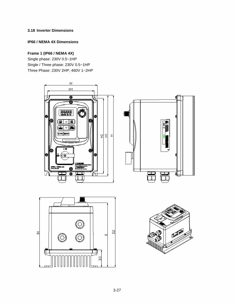
3.18 Inverter Dimensions
IP66 / NEMA 4X Dimensions
Frame 1 (IP66 / NEMA 4X)
Single phase: 230V 0.5~1HP
Single / Three phase: 230V 0.5~1HP
Three Phase: 230V 2HP; 460V 1~2HP
3-28
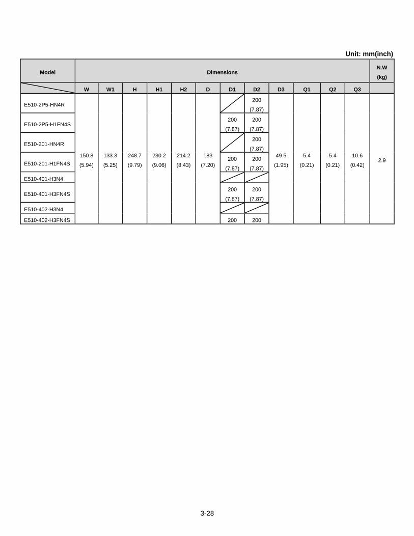
Unit: mm(inch)
Model Dimensions N.W
(kg)
W W1 H H1 H2 D D1 D2 D3 Q1 Q2 Q3
E510-2P5-HN4R
150.8
(5.94)
133.3
(5.25)
248.7
(9.79)
230.2
(9.06)
214.2
(8.43)
183
(7.20)
200
(7.87)
49.5
(1.95)
5.4
(0.21)
5.4
(0.21)
10.6
(0.42) 2.9
E510-2P5-H1FN4S 200
(7.87)
200
(7.87)
E510-201-HN4R 200
(7.87)
E510-201-H1FN4S 200
(7.87)
200
(7.87)
E510-401-H3N4
E510-401-H3FN4S 200
(7.87)
200
(7.87)
E510-402-H3N4
E510-402-H3FN4S 200 200
3-29
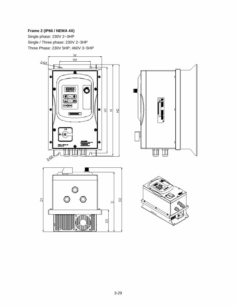
Frame 2 (IP66 / NEMA 4X)
Single phase: 230V 2~3HP
Single / Three phase: 230V 2~3HP
Three Phase: 230V 5HP; 460V 3~5HP
3-30
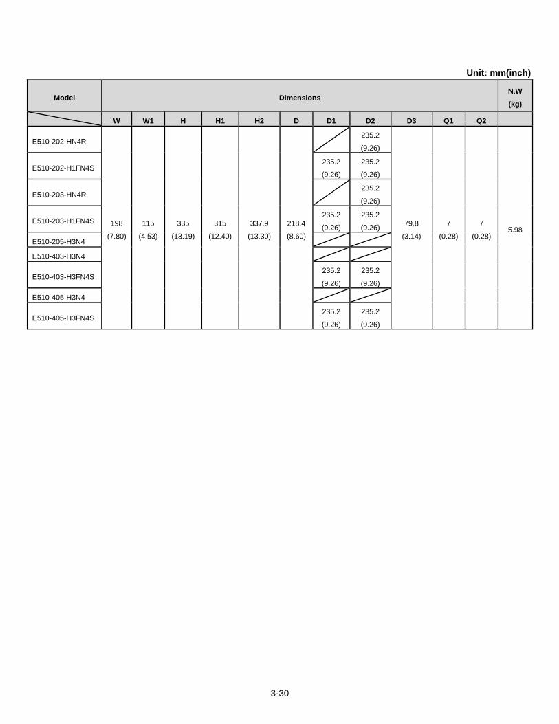
Unit: mm(inch)
Model Dimensions N.W
(kg)
W W1 H H1 H2 D D1 D2 D3 Q1 Q2
E510-202-HN4R
198
(7.80)
115
(4.53)
335
(13.19)
315
(12.40)
337.9
(13.30)
218.4
(8.60)
235.2
(9.26)
79.8
(3.14)
7
(0.28)
7
(0.28) 5.98
E510-202-H1FN4S 235.2
(9.26)
235.2
(9.26)
E510-203-HN4R 235.2
(9.26)
E510-203-H1FN4S 235.2
(9.26)
235.2
(9.26)
E510-205-H3N4
E510-403-H3N4
E510-403-H3FN4S 235.2
(9.26)
235.2
(9.26)
E510-405-H3N4
E510-405-H3FN4S 235.2
(9.26)
235.2
(9.26)
3-31
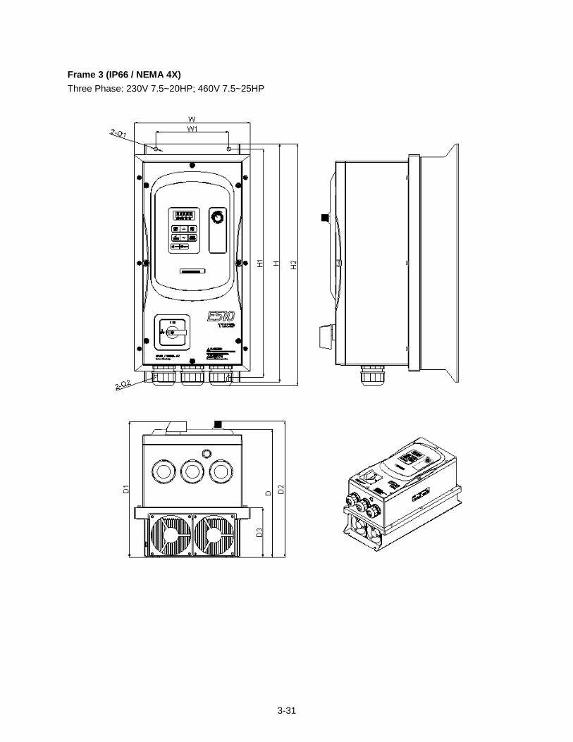
Frame 3 (IP66 / NEMA 4X)
Three Phase: 230V 7.5~20HP; 460V 7.5~25HP
3-32
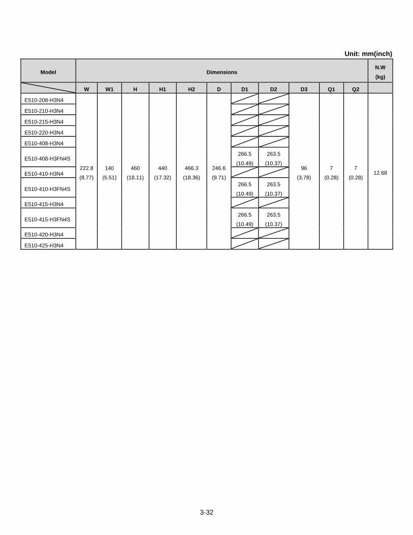
Unit: mm(inch)
Model Dimensions N.W
(kg)
W W1 H H1 H2 D D1 D2 D3 Q1 Q2
E510-208-H3N4
222.8
(8.77)
140
(5.51)
460
(18.11)
440
(17.32)
466.3
(18.36)
246.6
(9.71)
96
(3.78)
7
(0.28)
7
(0.28) 12.68
E510-210-H3N4
E510-215-H3N4
E510-220-H3N4
E510-408-H3N4
E510-408-H3FN4S 266.5
(10.49)
263.5
(10.37)
E510-410-H3N4
E510-410-H3FN4S 266.5
(10.49)
263.5
(10.37)
E510-415-H3N4
E510-415-H3FN4S 266.5
(10.49)
263.5
(10.37)
E510-420-H3N4
E510-425-H3N4
4-1
4. Keypad and Programming Functions
4.1 LED Keypad
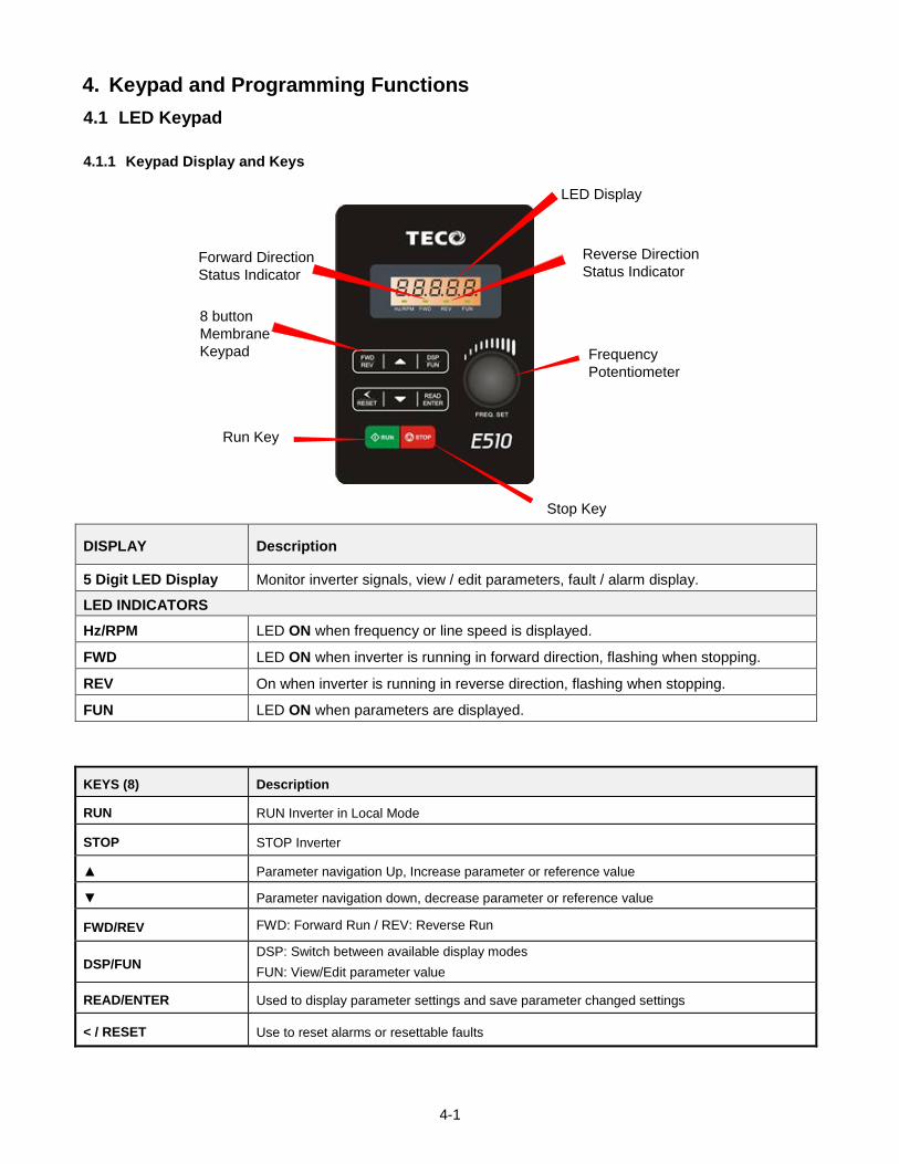
4.1.1 Keypad Display and Keys
LED Display
Run Key
8 button
Membrane
Keypad
Stop Key
Forward Direction
Status Indicator
Reverse Direction
Status Indicator
Frequency
Potentiometer
DISPLAY Description
5 Digit LED Display Monitor inverter signals, view / edit parameters, fault / alarm display.
LED INDICATORS
Hz/RPM LED ON when frequency or line speed is displayed.
FWD LED ON when inverter is running in forward direction, flashing when stopping.
REV On when inverter is running in reverse direction, flashing when stopping.
FUN LED ON when parameters are displayed.
KEYS (8) Description
RUN RUN Inverter in Local Mode
STOP STOP Inverter
Parameter navigation Up, Increase parameter or reference value
Parameter navigation down, decrease parameter or reference value
FWD/REV FWD: Forward Run / REV: Reverse Run
DSP/FUN DSP: Switch between available display modes
FUN: View/Edit parameter value
READ/ENTER Used to display parameter settings and save parameter changed settings
< / RESET Use to reset alarms or resettable faults
4-2
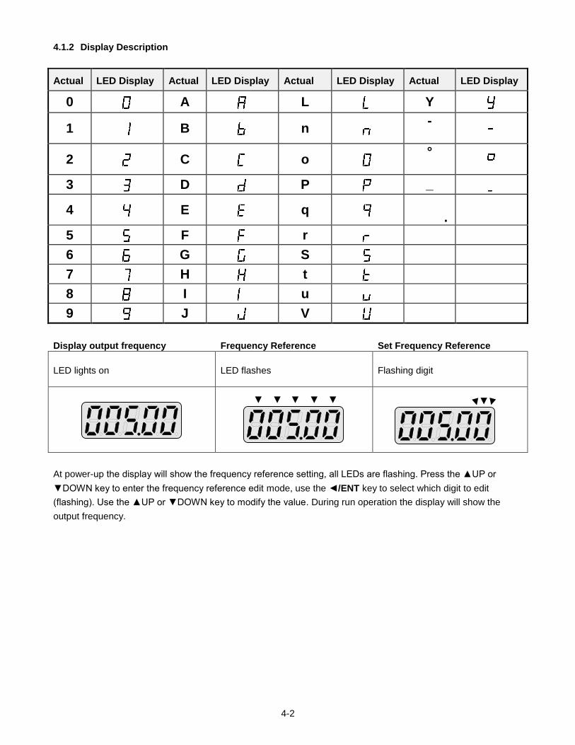
4.1.2 Display Description
Actual LED Display Actual LED Display Actual LED Display Actual LED Display
0 A L Y
1 B n -
2 C o °
3 D P _
4 E q
.
5 F r
6 G S
7 H t
8 I u
9 J V
Display output frequency Frequency Reference Set Frequency Reference
LED lights on LED flashes Flashing digit
At power-up the display will show the frequency reference setting, all LEDs are flashing. Press the UP or
DOWN key to enter the frequency reference edit mode, use the /ENT key to select which digit to edit
(flashing). Use the UP or DOWN key to modify the value. During run operation the display will show the
output frequency.
4-3
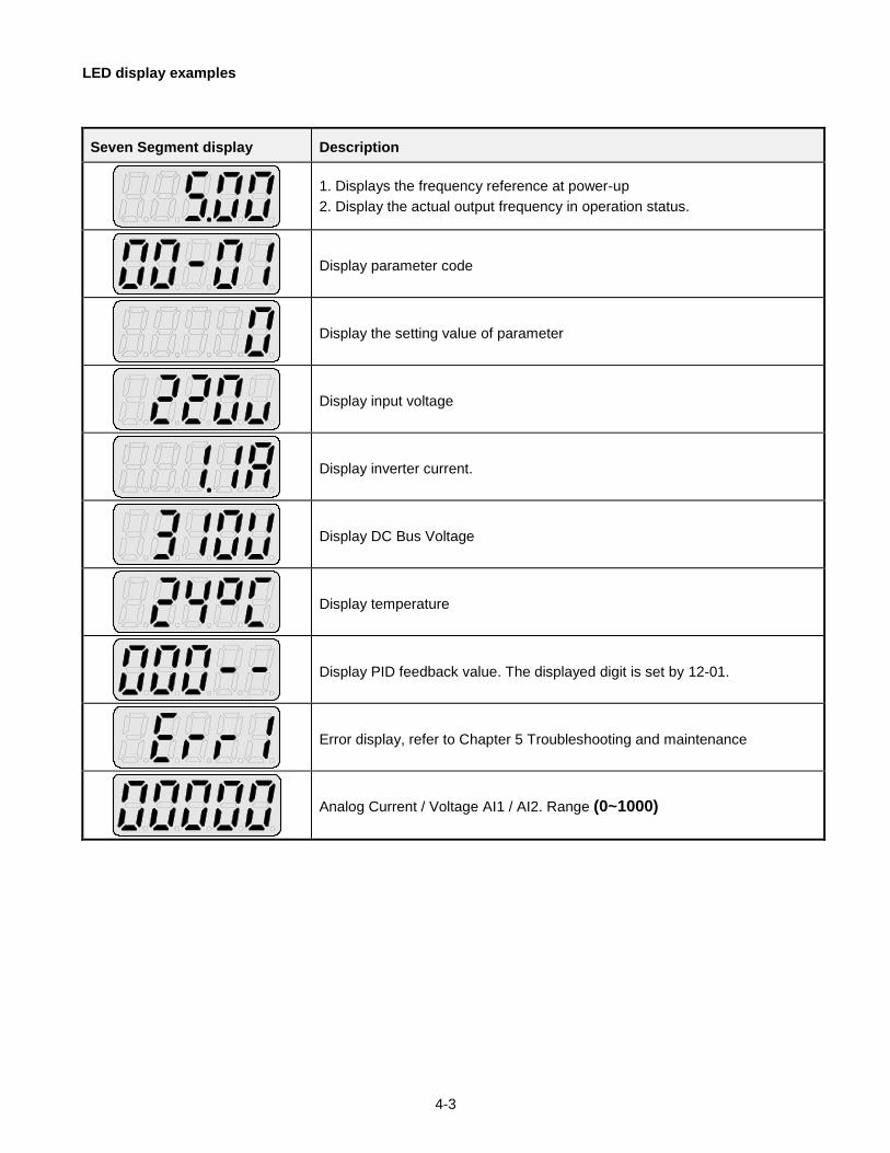
LED display examples
Seven Segment display Description
1. Displays the frequency reference at power-up
2. Display the actual output frequency in operation status.
Display parameter code
Display the setting value of parameter
Display input voltage
Display inverter current.
Display DC Bus Voltage
Display temperature
Display PID feedback value. The displayed digit is set by 12-01.
Error display, refer to Chapter 5 Troubleshooting and maintenance
Analog Current / Voltage AI1 / AI2. Range (0~1000)
4-4
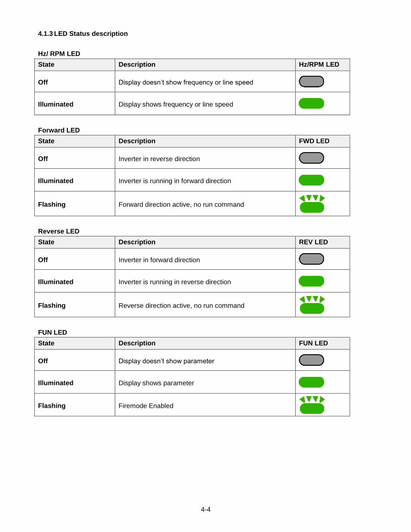
4.1.3 LED Status description
Hz/ RPM LED
State Description Hz/RPM LED
Off Display doesn’t show frequency or line speed
Illuminated Display shows frequency or line speed
Forward LED
State Description FWD LED
Off Inverter in reverse direction
Illuminated Inverter is running in forward direction
Flashing Forward direction active, no run command
Reverse LED
State Description REV LED
Off Inverter in forward direction
Illuminated Inverter is running in reverse direction
Flashing Reverse direction active, no run command
FUN LED
State Description FUN LED
Off Display doesn’t show parameter
Illuminated Display shows parameter
Flashing Firemode Enabled
4-5
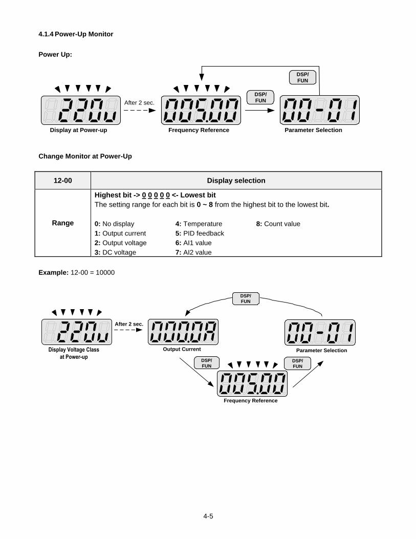
4.1.4 Power-Up Monitor
Power Up:
DSP/
FUN
DSP/
FUN
After 2 sec.
Display at Power-up Frequency Reference Parameter Selection
Change Monitor at Power-Up
12-00 Display selection
Range
Highest bit -> 0 0 0 0 0 <- Lowest bit
The setting range for each bit is 0 ~ 8 from the highest bit to the lowest bit.
0: No display 4: Temperature 8: Count value
1: Output current 5: PID feedback
2: Output voltage 6: AI1 value
3: DC voltage 7: AI2 value
Example: 12-00 = 10000
DSP/
FUN
DSP/
FUN
After 2 sec.
Parameter SelectionOutput Current
Frequency Reference
Display Voltage Class
at Power-upDSP/
FUN
4-6
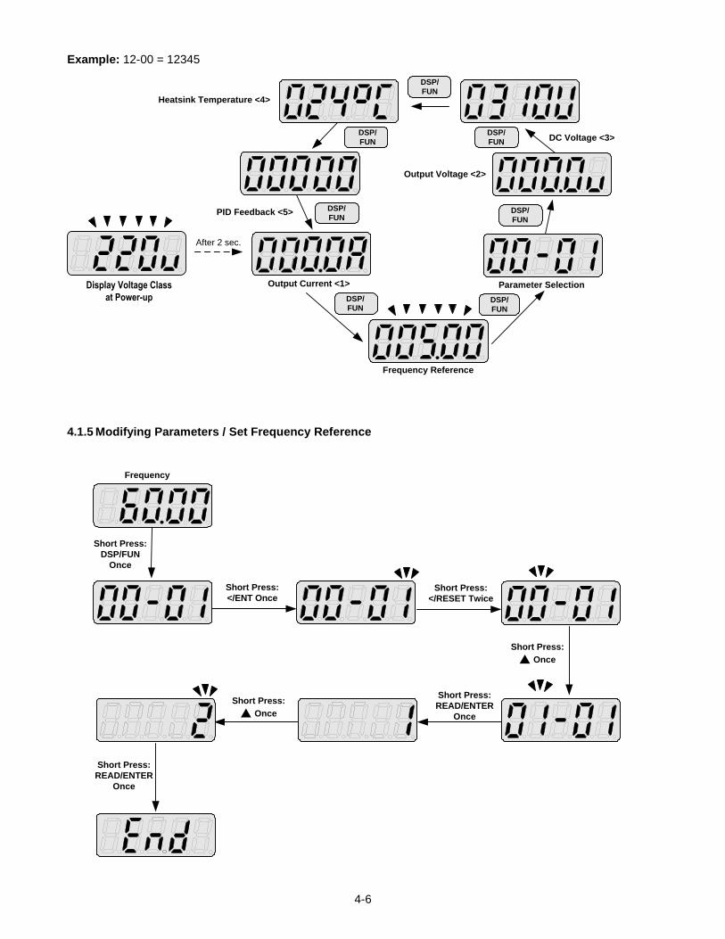
Example: 12-00 = 12345
DSP/
FUNDSP/
FUN
DSP/
FUN
DSP/
FUN
DSP/
FUN
DSP/
FUN
DSP/
FUN
After 2 sec.
Display Voltage Class
at Power-up
Output Current <1> Parameter Selection
Output Voltage <2>
DC Voltage <3>
Heatsink Temperature <4>
PID Feedback <5>
Frequency Reference
4.1.5 Modifying Parameters / Set Frequency Reference
Frequency
Short Press:
DSP/FUN
Once
Short Press:
</ENT OnceShort Press:
</RESET Twice
Short Press:
Once
Short Press:
READ/ENTER
Once
Short Press:
Once
Short Press:
READ/ENTER
Once
4-7
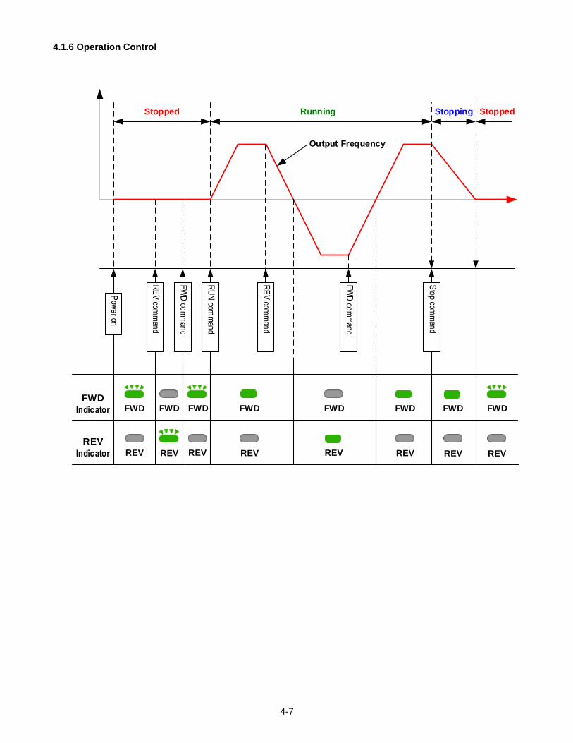
4.1.6 Operation Control
RE
V com
man
d
FW
D co
mm
and
RU
N com
man
d
RE
V com
man
d
Sto
p comm
and
FW
D co
mm
and
FWD
Indicator
REV
Indicator REVREV REV
FWDFWD FWD FWD FWD FWD FWD
REV REV REV REVP
owe
r on
Output Frequency
Running StoppingStopped
FWD
REV
Stopped
4-8
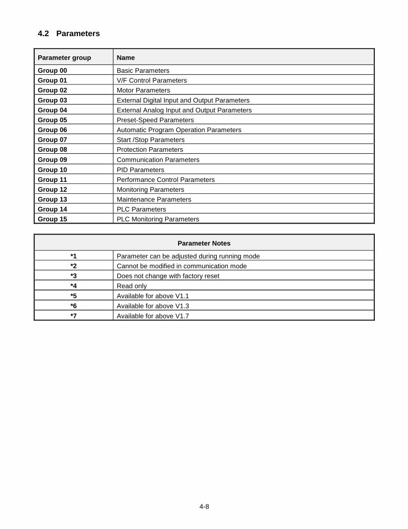
4.2 Parameters
Parameter group Name
Group 00 Basic Parameters
Group 01 V/F Control Parameters
Group 02 Motor Parameters
Group 03 External Digital Input and Output Parameters
Group 04 External Analog Input and Output Parameters
Group 05 Preset-Speed Parameters
Group 06 Automatic Program Operation Parameters
Group 07 Start /Stop Parameters
Group 08 Protection Parameters
Group 09 Communication Parameters
Group 10 PID Parameters
Group 11 Performance Control Parameters
Group 12 Monitoring Parameters
Group 13 Maintenance Parameters
Group 14 PLC Parameters
Group 15 PLC Monitoring Parameters
Parameter Notes
*1 Parameter can be adjusted during running mode
*2 Cannot be modified in communication mode
*3 Does not change with factory reset
*4 Read only
*5 Available for above V1.1
*6 Available for above V1.3
*7 Available for above V1.7
4-9
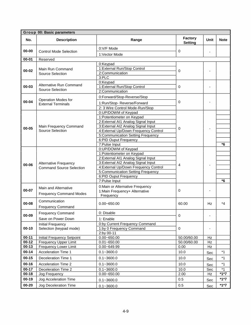
Group 00: Basic parameters
No. Description Range Factory
Setting Unit Note
00-00 Control Mode Selection 0:V/F Mode
0 - 1:Vector Mode
00-01 Reserved
00-02 Main Run Command
Source Selection
0:Keypad
0 - 1:External Run/Stop Control
2:Communication
3:PLC
00-03 Alternative Run Command
Source Selection
0:Keypad
0 - 1:External Run/Stop Control
2:Communication
00-04 Operation Modes for External Terminals
0:Forward/Stop-Reverse/Stop
0 - 1:Run/Stop- Reverse/Forward
2: 3 Wire Control Mode-Run/Stop
00-05 Main Frequency Command Source Selection
0:UP/DOWM of Keypad
0 -
1:Potentiometer on Keypad
2:External AI1 Analog Signal Input
3:External AI2 Analog Signal Input
4:External Up/Down Frequency Control
5:Communication Setting Frequency
6:PID Ouput Frequency
7:Pulse Input *6
00-06 Alternative Frequency
Command Source Selection
0:UP/DOWM of Keypad
4 -
1:Potentiometer on Keypad
2:External AI1 Analog Signal Input
3:External AI2 Analog Signal Input
4:External Up/Down Frequency Control
5:Communication Setting Frequency
6:PID Ouput Frequency
7:Pulse Input *6
00-07 Main and Alternative
Frequency Command Modes
0:Main or Alternative Frequency
1:Main Frequency+ Alternative Frequency
0 -
00-08 Communication
Frequency Command 0.00~650.00 60.00 Hz *4
00-09 Frequency Command
Save on Power Down
0: Disable 0 -
1: Enable
00-10 Initial Frequency Selection (keypad mode)
0:by Current Frequency Command
0 - 1:by 0 Frequency Command
2:by 00-11
00-11 Initial Frequency Setpoint 0.00~650.00 50.00/60.00 Hz
00-12 Frequency Upper Limit 0.01~650.00 50.00/60.00 Hz
00-13 Frequency Lower Limit 0.00~649.99 0.00 Hz
00-14 Acceleration Time 1 0.1~3600.0 10.0 Sec *1
00-15 Deceleration Time 1 0.1~3600.0 10.0 Sec *1
00-16 Acceleration Time 2 0.1~3600.0 10.0 Sec *1
00-17 Deceleration Time 2 0.1~3600.0 10.0 Sec *1
00-18 Jog Frequency 0.00~650.00 2.00 Hz *1*7
00-19 Jog Acceleration Time 0.1~3600.0 0.5 Sec *1*7
00-20 Jog Deceleration Time 0.1~3600.0 0.5 Sec *1*7
4-10
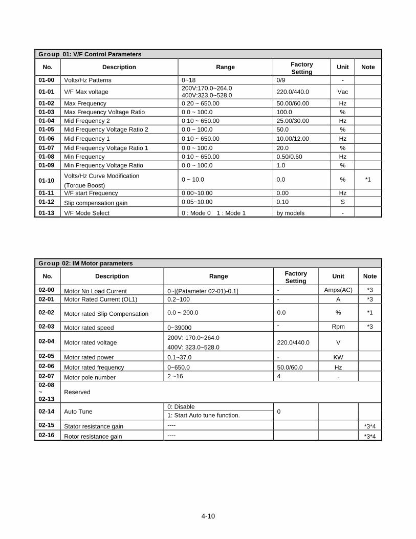
Group 01: V/F Control Parameters
No. Description Range Factory
Setting Unit Note
01-00 Volts/Hz Patterns 0~18 0/9 -
01-01 V/F Max voltage 200V:170.0~264.0 400V:323.0~528.0
220.0/440.0 Vac
01-02 Max Frequency 0.20 ~ 650.00 50.00/60.00 Hz
01-03 Max Frequency Voltage Ratio 0.0 ~ 100.0 100.0 %
01-04 Mid Frequency 2 0.10 ~ 650.00 25.00/30.00 Hz
01-05 Mid Frequency Voltage Ratio 2 0.0 ~ 100.0 50.0 %
01-06 Mid Frequency 1 0.10 ~ 650.00 10.00/12.00 Hz
01-07 Mid Frequency Voltage Ratio 1 0.0 ~ 100.0 20.0 %
01-08 Min Frequency 0.10 ~ 650.00 0.50/0.60 Hz
01-09 Min Frequency Voltage Ratio 0.0 ~ 100.0 1.0 %
01-10 Volts/Hz Curve Modification
(Torque Boost) 0 ~ 10.0 0.0 % *1
01-11 V/F start Frequency 0.00~10.00 0.00 Hz
01-12 Slip compensation gain 0.05~10.00 0.10 S
01-13 V/F Mode Select 0 : Mode 0 1 : Mode 1 by models -
Group 02: IM Motor parameters
No. Description Range Factory
Setting Unit Note
02-00 Motor No Load Current 0~[(Patameter 02-01)-0.1] - Amps(AC) *3
02-01 Motor Rated Current (OL1) 0.2~100 - A *3
02-02 Motor rated Slip Compensation 0.0 ~ 200.0 0.0 % *1
02-03 Motor rated speed 0~39000 - Rpm *3
02-04 Motor rated voltage 200V: 170.0~264.0
400V: 323.0~528.0 220.0/440.0 V
02-05 Motor rated power 0.1~37.0 - KW
02-06 Motor rated frequency 0~650.0 50.0/60.0 Hz
02-07 Motor pole number 2 ~16 4 -
02-08 ~ 02-13
Reserved
02-14 Auto Tune 0: Disable
0 1: Start Auto tune function.
02-15 Stator resistance gain ---- *3*4
02-16 Rotor resistance gain ---- *3*4
4-11
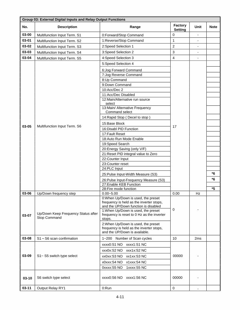
Group 03: External Digital Inputs and Relay Output Functions
No. Description Range Factory
Setting Unit Note
03-00 Multifunction Input Term. S1 0:Forward/Stop Command 0 -
03-01 Multifunction Input Term. S2 1:Reverse/Stop Command 1 -
03-02 Multifunction Input Term. S3 2:Speed Selection 1 2 -
03-03 Multifunction Input Term. S4 3:Speed Selection 2 3 -
03-04 Multifunction Input Term. S5 4:Speed Selection 3 4 -
03-05 Multifunction Input Term. S6
5:Speed Selection 4
17
6:Jog Forward Command
7:Jog Reverse Command
8:Up Command
9:Down Command
10:Acc/Dec 2
11:Acc/Dec Disabled
12:Main/Alternative run source select
13:Main/ Alternative Frequency Command select
14:Rapid Stop ( Decel to stop )
15:Base Block
16:Disabl PID Function
17:Fault Reset
18:Auto Run Mode Enable
19:Speed Search
20:Energy Saving (only V/F)
21:Reset PID integral value to Zero
22:Counter Input
23:Counter reset
24:PLC Input
25:Pulse Input-Width Measure (S3) *6
26:Pulse Input-Frequency Measure (S3) *6
27:Enable KEB Function
28:Fire mode function *5
03-06 Up/Down frequency step 0.00~5.00 0.00 Hz
03-07 Up/Down Keep Frequency Status after Stop Command
0:When Up/Down is used, the preset frequency is held as the inverter stops, and the UP/Down function is disabled
0
-
1:When Up/Down is used, the preset frequency is reset to 0 Hz as the inverter stops.
2:When Up/Down is used, the preset frequency is held as the inverter stops, and the UP/Down is available.
03-08 S1~S6 scan confirmation 1~200 Number of Scan cycles 10 2ms
03-09 S1~ S5 switch type select
xxxx0:S1 NO xxxx1:S1 NC
00000 -
xxx0x:S2 NO xxx1x:S2 NC
xx0xx:S3 NO xx1xx:S3 NC
x0xxx:S4 NO x1xxx:S4 NC
0xxxx:S5 NO 1xxxx:S5 NC
03-10 S6 switch type select xxxx0:S6 NO xxxx1:S6 NC 00000 -
03-11 Output Relay RY1 0:Run 0 -
4-12
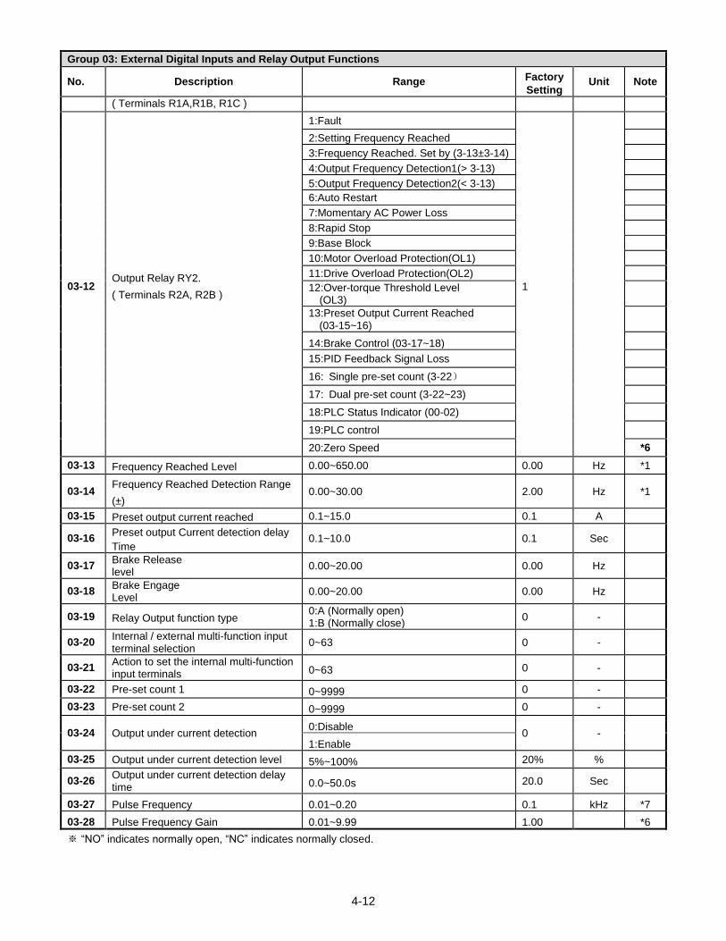
Group 03: External Digital Inputs and Relay Output Functions
No. Description Range Factory
Setting Unit Note
( Terminals R1A,R1B, R1C )
03-12 Output Relay RY2.
( Terminals R2A, R2B )
1:Fault
1
2:Setting Frequency Reached
3:Frequency Reached. Set by (3-13±3-14)
4:Output Frequency Detection1(> 3-13)
5:Output Frequency Detection2(< 3-13)
6:Auto Restart
7:Momentary AC Power Loss
8:Rapid Stop
9:Base Block
10:Motor Overload Protection(OL1)
11:Drive Overload Protection(OL2)
12:Over-torque Threshold Level (OL3)
13:Preset Output Current Reached (03-15~16)
14:Brake Control (03-17~18)
15:PID Feedback Signal Loss
16: Single pre-set count (3-22)
17: Dual pre-set count (3-22~23)
18:PLC Status Indicator (00-02)
19:PLC control
20:Zero Speed *6
03-13 Frequency Reached Level 0.00~650.00 0.00 Hz *1
03-14 Frequency Reached Detection Range
(±) 0.00~30.00 2.00 Hz *1
03-15 Preset output current reached 0.1~15.0 0.1 A
03-16 Preset output Current detection delay
Time 0.1~10.0 0.1 Sec
03-17 Brake Release level
0.00~20.00 0.00 Hz
03-18 Brake Engage Level
0.00~20.00 0.00 Hz
03-19 Relay Output function type 0:A (Normally open) 1:B (Normally close)
0 -
03-20 Internal / external multi-function input terminal selection
0~63 0 -
03-21 Action to set the internal multi-function input terminals 0~63 0 -
03-22 Pre-set count 1 0~9999 0 -
03-23 Pre-set count 2 0~9999 0 -
03-24 Output under current detection 0:Disable
0 - 1:Enable
03-25 Output under current detection level 5%~100% 20% %
03-26 Output under current detection delay time 0.0~50.0s 20.0 Sec
03-27 Pulse Frequency 0.01~0.20 0.1 kHz *7
03-28 Pulse Frequency Gain 0.01~9.99 1.00 *6
※ “NO” indicates normally open, “NC” indicates normally closed.
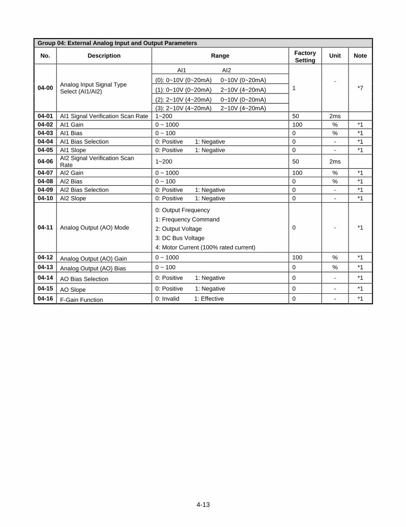
4-13
Group 04: External Analog Input and Output Parameters
No. Description Range Factory
Setting Unit Note
04-00 Analog Input Signal Type Select (AI1/AI2)
AI1 AI2
1 -
*7
(0): 0~10V (0~20mA) 0~10V (0~20mA)
(1): 0~10V (0~20mA) 2~10V (4~20mA)
(2): 2~10V (4~20mA) 0~10V (0~20mA)
(3): 2~10V (4~20mA) 2~10V (4~20mA)
04-01 AI1 Signal Verification Scan Rate 1~200 50 2ms
04-02 AI1 Gain 0 ~ 1000 100 % *1
04-03 AI1 Bias 0 ~ 100 0 % *1
04-04 AI1 Bias Selection 0: Positive 1: Negative 0 - *1
04-05 AI1 Slope 0: Positive 1: Negative 0 - *1
04-06 AI2 Signal Verification Scan Rate
1~200 50 2ms
04-07 AI2 Gain 0 ~ 1000 100 % *1
04-08 AI2 Bias 0 ~ 100 0 % *1
04-09 AI2 Bias Selection 0: Positive 1: Negative 0 - *1
04-10 AI2 Slope 0: Positive 1: Negative 0 - *1
04-11 Analog Output (AO) Mode
0: Output Frequency
1: Frequency Command
2: Output Voltage
3: DC Bus Voltage
4: Motor Current (100% rated current)
0 - *1
04-12 Analog Output (AO) Gain 0 ~ 1000 100 % *1
04-13 Analog Output (AO) Bias 0 ~ 100 0 % *1
04-14 AO Bias Selection 0: Positive 1: Negative 0 - *1
04-15 AO Slope 0: Positive 1: Negative 0 - *1
04-16 F-Gain Function 0: Invalid 1: Effective 0 - *1
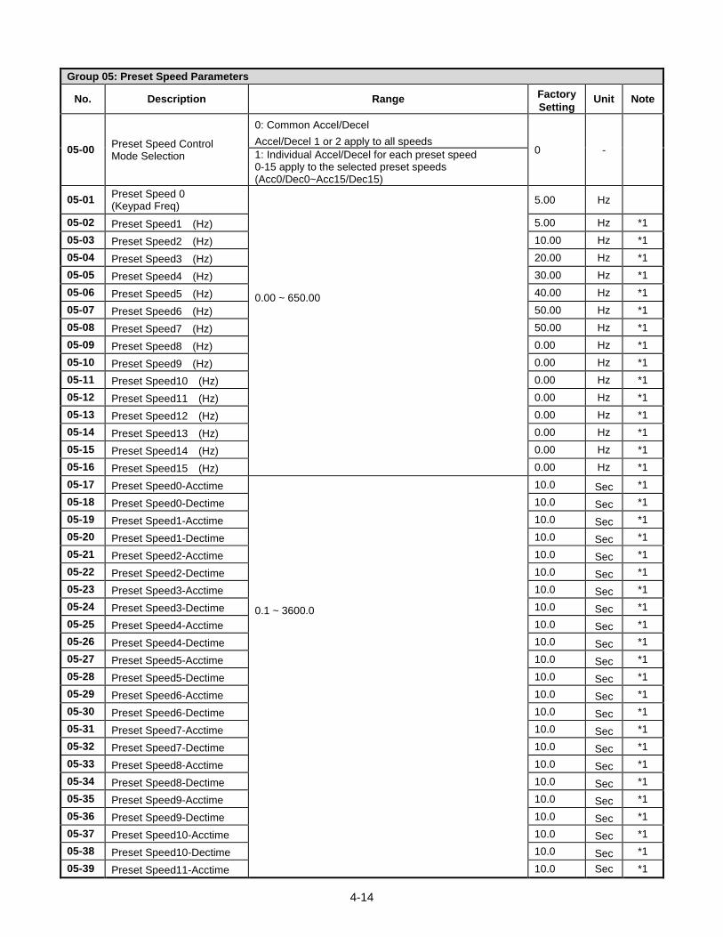
4-14
Group 05: Preset Speed Parameters
No. Description Range Factory
Setting Unit Note
05-00 Preset Speed Control Mode Selection
0: Common Accel/Decel
Accel/Decel 1 or 2 apply to all speeds 0 - 1: Individual Accel/Decel for each preset speed
0-15 apply to the selected preset speeds (Acc0/Dec0~Acc15/Dec15)
05-01 Preset Speed 0 (Keypad Freq)
0.00 ~ 650.00
5.00 Hz
05-02 Preset Speed1 (Hz) 5.00 Hz *1
05-03 Preset Speed2 (Hz) 10.00 Hz *1
05-04 Preset Speed3 (Hz) 20.00 Hz *1
05-05 Preset Speed4 (Hz) 30.00 Hz *1
05-06 Preset Speed5 (Hz) 40.00 Hz *1
05-07 Preset Speed6 (Hz) 50.00 Hz *1
05-08 Preset Speed7 (Hz) 50.00 Hz *1
05-09 Preset Speed8 (Hz) 0.00 Hz *1
05-10 Preset Speed9 (Hz) 0.00 Hz *1
05-11 Preset Speed10 (Hz) 0.00 Hz *1
05-12 Preset Speed11 (Hz) 0.00 Hz *1
05-13 Preset Speed12 (Hz) 0.00 Hz *1
05-14 Preset Speed13 (Hz) 0.00 Hz *1
05-15 Preset Speed14 (Hz) 0.00 Hz *1
05-16 Preset Speed15 (Hz) 0.00 Hz *1
05-17 Preset Speed0-Acctime
0.1 ~ 3600.0
10.0 Sec *1
05-18 Preset Speed0-Dectime 10.0 Sec *1
05-19 Preset Speed1-Acctime 10.0 Sec *1
05-20 Preset Speed1-Dectime 10.0 Sec *1
05-21 Preset Speed2-Acctime 10.0 Sec *1
05-22 Preset Speed2-Dectime 10.0 Sec *1
05-23 Preset Speed3-Acctime 10.0 Sec *1
05-24 Preset Speed3-Dectime 10.0 Sec *1
05-25 Preset Speed4-Acctime 10.0 Sec *1
05-26 Preset Speed4-Dectime 10.0 Sec *1
05-27 Preset Speed5-Acctime 10.0 Sec *1
05-28 Preset Speed5-Dectime 10.0 Sec *1
05-29 Preset Speed6-Acctime 10.0 Sec *1
05-30 Preset Speed6-Dectime 10.0 Sec *1
05-31 Preset Speed7-Acctime 10.0 Sec *1
05-32 Preset Speed7-Dectime 10.0 Sec *1
05-33 Preset Speed8-Acctime 10.0 Sec *1
05-34 Preset Speed8-Dectime 10.0 Sec *1
05-35 Preset Speed9-Acctime 10.0 Sec *1
05-36 Preset Speed9-Dectime 10.0 Sec *1
05-37 Preset Speed10-Acctime 10.0 Sec *1
05-38 Preset Speed10-Dectime 10.0 Sec *1
05-39 Preset Speed11-Acctime 10.0 Sec *1
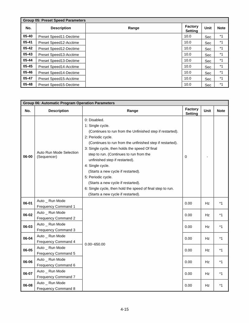
4-15
Group 05: Preset Speed Parameters
No. Description Range Factory
Setting Unit Note
05-40 Preset Speed11-Dectime 10.0 Sec *1
05-41 Preset Speed12-Acctime 10.0 Sec *1
05-42 Preset Speed12-Dectime 10.0 Sec *1
05-43 Preset Speed13-Acctime 10.0 Sec *1
05-44 Preset Speed13-Dectime 10.0 Sec *1
05-45 Preset Speed14-Acctime 10.0 Sec *1
05-46 Preset Speed14-Dectime 10.0 Sec *1
05-47 Preset Speed15-Acctime 10.0 Sec *1
05-48 Preset Speed15-Dectime 10.0 Sec *1
Group 06: Automatic Program Operation Parameters
No. Description Range Factory
Setting Unit Note
06-00 Auto Run Mode Selection (Sequencer)
0: Disabled.
1: Single cycle.
(Continues to run from the Unfinished step if restarted).
2: Periodic cycle.
(Continues to run from the unfinished step if restarted).
3: Single cycle, then holds the speed Of final
step to run. (Continues to run from the
unfinished step if restarted).
4: Single cycle.
(Starts a new cycle if restarted).
5: Periodic cycle.
(Starts a new cycle if restarted).
6: Single cycle, then hold the speed of final step to run.
(Starts a new cycle if restarted).
0 -
06-01 Auto _ Run Mode
Frequency Command 1
0.00~650.00
0.00 Hz *1
06-02 Auto _ Run Mode
Frequency Command 2 0.00 Hz *1
06-03 Auto _ Run Mode
Frequency Command 3 0.00 Hz *1
06-04 Auto _ Run Mode
Frequency Command 4 0.00 Hz *1
06-05 Auto _ Run Mode
Frequency Command 5 0.00 Hz *1
06-06 Auto _ Run Mode
Frequency Command 6 0.00 Hz *1
06-07 Auto _ Run Mode
Frequency Command 7 0.00 Hz *1
06-08 Auto _ Run Mode
Frequency Command 8 0.00 Hz *1
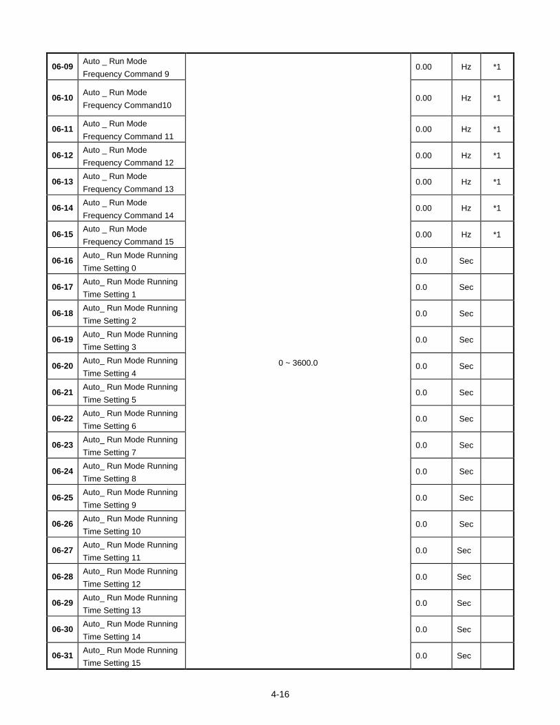
4-16
06-09 Auto _ Run Mode
Frequency Command 9
0 ~ 3600.0
0.00 Hz *1
06-10 Auto _ Run Mode
Frequency Command10 0.00 Hz *1
06-11 Auto _ Run Mode
Frequency Command 11 0.00 Hz *1
06-12 Auto _ Run Mode
Frequency Command 12 0.00 Hz *1
06-13 Auto _ Run Mode
Frequency Command 13 0.00 Hz *1
06-14 Auto _ Run Mode
Frequency Command 14 0.00 Hz *1
06-15 Auto _ Run Mode
Frequency Command 15 0.00 Hz *1
06-16 Auto_ Run Mode Running
Time Setting 0 0.0 Sec
06-17 Auto_ Run Mode Running
Time Setting 1 0.0 Sec
06-18 Auto_ Run Mode Running
Time Setting 2 0.0 Sec
06-19 Auto_ Run Mode Running
Time Setting 3 0.0 Sec
06-20 Auto_ Run Mode Running
Time Setting 4 0.0 Sec
06-21 Auto_ Run Mode Running
Time Setting 5 0.0 Sec
06-22 Auto_ Run Mode Running
Time Setting 6 0.0 Sec
06-23 Auto_ Run Mode Running
Time Setting 7 0.0 Sec
06-24 Auto_ Run Mode Running
Time Setting 8 0.0 Sec
06-25 Auto_ Run Mode Running
Time Setting 9 0.0 Sec
06-26 Auto_ Run Mode Running
Time Setting 10 0.0 Sec
06-27 Auto_ Run Mode Running
Time Setting 11 0.0 Sec
06-28 Auto_ Run Mode Running
Time Setting 12 0.0 Sec
06-29 Auto_ Run Mode Running
Time Setting 13 0.0 Sec
06-30 Auto_ Run Mode Running
Time Setting 14 0.0 Sec
06-31 Auto_ Run Mode Running
Time Setting 15 0.0 Sec
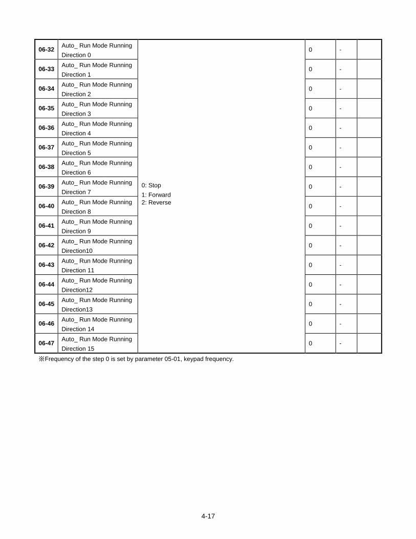
4-17
06-32 Auto_ Run Mode Running
Direction 0
0: Stop
1: Forward
2: Reverse
0 -
06-33 Auto_ Run Mode Running
Direction 1 0 -
06-34 Auto_ Run Mode Running
Direction 2 0 -
06-35 Auto_ Run Mode Running
Direction 3 0 -
06-36 Auto_ Run Mode Running
Direction 4 0 -
06-37 Auto_ Run Mode Running
Direction 5 0 -
06-38 Auto_ Run Mode Running
Direction 6 0 -
06-39 Auto_ Run Mode Running
Direction 7 0 -
06-40 Auto_ Run Mode Running
Direction 8 0 -
06-41 Auto_ Run Mode Running
Direction 9 0 -
06-42 Auto_ Run Mode Running
Direction10 0 -
06-43 Auto_ Run Mode Running
Direction 11 0 -
06-44 Auto_ Run Mode Running
Direction12 0 -
06-45 Auto_ Run Mode Running
Direction13 0 -
06-46 Auto_ Run Mode Running
Direction 14 0 -
06-47 Auto_ Run Mode Running
Direction 15 0 -
※ Frequency of the step 0 is set by parameter 05-01, keypad frequency.
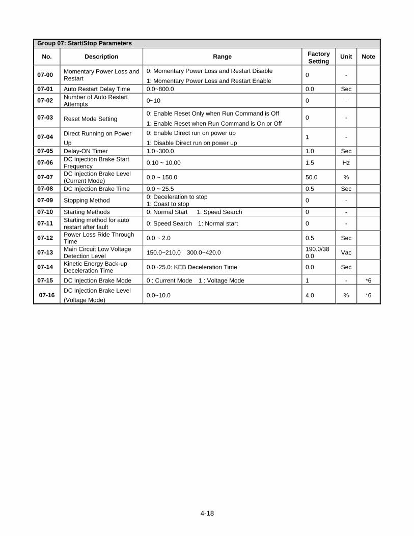
4-18
Group 07: Start/Stop Parameters
No. Description Range Factory
Setting Unit Note
07-00 Momentary Power Loss and Restart
0: Momentary Power Loss and Restart Disable
1: Momentary Power Loss and Restart Enable 0 -
07-01 Auto Restart Delay Time 0.0~800.0 0.0 Sec
07-02 Number of Auto Restart Attempts
0~10 0 -
07-03 Reset Mode Setting 0: Enable Reset Only when Run Command is Off
1: Enable Reset when Run Command is On or Off 0 -
07-04 Direct Running on Power
Up
0: Enable Direct run on power up
1: Disable Direct run on power up 1 -
07-05 Delay-ON Timer 1.0~300.0 1.0 Sec
07-06 DC Injection Brake Start Frequency
0.10 ~ 10.00 1.5 Hz
07-07 DC Injection Brake Level (Current Mode)
0.0 ~ 150.0 50.0 %
07-08 DC Injection Brake Time 0.0 ~ 25.5 0.5 Sec
07-09 Stopping Method 0: Deceleration to stop 1: Coast to stop
0 -
07-10 Starting Methods 0: Normal Start 1: Speed Search 0 -
07-11 Starting method for auto restart after fault
0: Speed Search 1: Normal start 0 -
07-12 Power Loss Ride Through Time
0.0 ~ 2.0 0.5 Sec
07-13 Main Circuit Low Voltage Detection Level
150.0~210.0 300.0~420.0 190.0/380.0
Vac
07-14 Kinetic Energy Back-up Deceleration Time
0.0~25.0: KEB Deceleration Time 0.0 Sec
07-15 DC Injection Brake Mode 0 : Current Mode 1 : Voltage Mode 1 - *6
07-16 DC Injection Brake Level
(Voltage Mode) 0.0~10.0 4.0 % *6
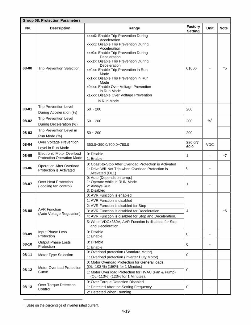
4-19
Group 08: Protection Parameters
No. Description Range Factory
Setting Unit Note
08-00 Trip Prevention Selection
xxxx0: Enable Trip Prevention During Acceleration
xxxx1: Disable Trip Prevention During Acceleration
xxx0x: Enable Trip Prevention During Deceleration
xxx1x: Disable Trip Prevention During Deceleration
xx0xx: Enable Trip Prevention in Run Mode
xx1xx: Disable Trip Prevention in Run Mode
x0xxx: Enable Over Voltage Prevention in Run Mode
x1xxx: Disable Over Voltage Prevention
in Run Mode
01000 - *5
08-01 Trip Prevention Level
During Acceleration (%) 50 ~ 200 200
%1
08-02 Trip Prevention Level
During Deceleration (%) 50 ~ 200 200
08-03 Trip Prevention Level in
Run Mode (%) 50 ~ 200 200
08-04 Over Voltage Prevention
Level in Run Mode 350.0~390.0/700.0~780.0
380.0/760.0
VDC
08-05 Electronic Motor Overload Protection Operation Mode
0: Disable
1: Enable 1 - *7
08-06 Operation After Overload Protection is Activated
0: Coast-to-Stop After Overload Protection is Activated
1: Drive Will Not Trip when Overload Protection is Activated (OL1)
0 -
08-07 Over Heat Protection ( cooling fan control)
0: Auto (Depends on temp.) 1: Operate while in RUN Mode 2: Always Run 3: Disabled
1 -
08-08 AVR Function (Auto Voltage Regulation)
0: AVR Function is enabled
4 - *5
1: AVR Function is disabled
2: AVR Function is disabled for Stop
3: AVR Function is disabled for Deceleration.
4: AVR Function is disabled for Stop and Deceleration.
5: When VDC>360V, AVR Function is disabled for Stop and Deceleration.
08-09 Input Phase Loss Protection
0: Disable 1: Enable
0 -
08-10 Output Phase Losts Protection
0: Disable 0 -
1: Enable
08-11 Motor Type Selection 0: Overload protection (Standard Motor)
0 - 1: Overload protection (Inverter Duty Motor)
08-12 Motor Overload Protection Curve
0: Motor Overload Protection for General loads (OL=103 %) (150% for 1 Minutes)
0 - 1: Motor Over load Protection for HVAC (Fan & Pump)
(OL=113%) (123% for 1 Minutes).
08-13 Over Torque Detection Control
0: Over Torque Detection Disabled
0 - 1: Detected After the Setting Frequency
2: Detected When Running
1 Base on the percentage of inverter rated current.
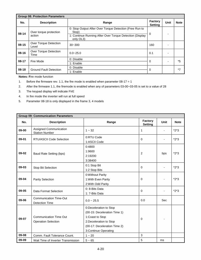
4-20
Group 08: Protection Parameters
No. Description Range Factory
Setting Unit Note
08-14 Over torque protection action
0: Stop Output After Over Torque Detection (Free Run to Stop)
0 - 1: Continue Running After Over Torque Detection (Display
only OL3)
08-15 Over Torque Detection Level
30~300 160 -
08-16 Over Torque Detection Time
0.0~25.0 0.1 -
08-17 Fire Mode 0: Disable
0 - *5 1: Enable
08-18 Ground Fault Detection 0: Disable
0 *7 1: Enable
Notes: Fire mode function
1. Before the firmware rev. 1.1, the fire mode is enabled when parameter 08-17 = 1
2. After the firmware 1.1, the firemode is enabled when any of parameters 03-00~03-05 is set to a value of 28
3. The keypad display will indicate FIrE
4. In fire mode the inverter will run at full speed
5. Parameter 08-18 is only displayed in the frame 3, 4 models
Group 09: Communication Parameters
No. Description Range Factory
Setting Unit Note
09-00 Assigned Communication
Station Number 1 ~ 32 1 - *2*3
09-01 RTU/ASCII Code Selection 0:RTU Code
1:ASCII Code 0 - *2*3
09-02 Baud Rate Setting (bps)
0:4800
1:9600
2:19200
3:38400
2 bps *2*3
09-03 Stop Bit Selection 0:1 Stop Bit
1:2 Stop Bits 0 - *2*3
09-04 Parity Selection
0:Without Parity
1:With Even Parity
2:With Odd Parity
0 - *2*3
09-05 Data Format Selection 0: 8-Bits Data
1: 7-Bits Data 0 - *2*3
09-06 Communication Time-Out
Detection Time 0.0 ~ 25.5 0.0 Sec
09-07 Communication Time Out
Operation Selection
0:Deceleration to Stop
(00-15: Deceleration Time 1)
1:Coast to Stop
2:Deceleration to Stop
(00-17: Deceleration Time 2)
3:Continue Operating
0 -
09-08 Comm. Fault Tolerance Count. 1 ~ 20 3
09-09 Wait Time of Inverter Transmission 5 ~ 65 5 ms
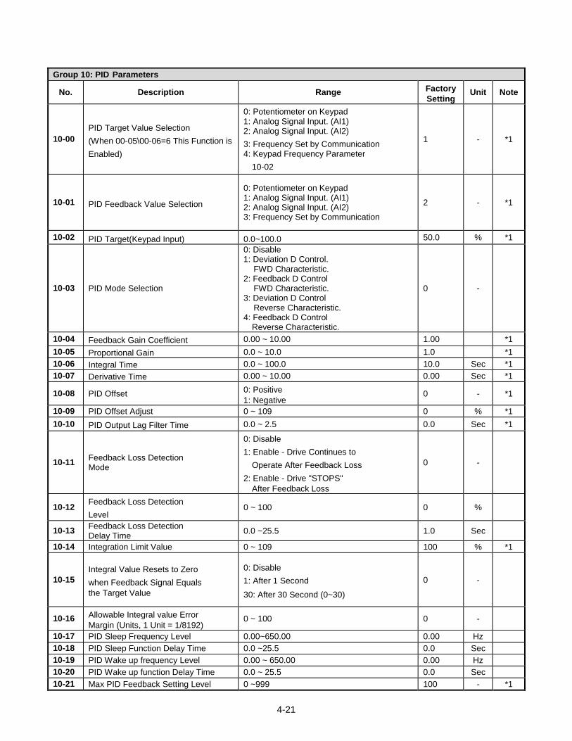
4-21
Group 10: PID Parameters
No. Description Range Factory
Setting Unit Note
10-00
PID Target Value Selection
(When 00-05\00-06=6 This Function is
Enabled)
0: Potentiometer on Keypad 1: Analog Signal Input. (AI1) 2: Analog Signal Input. (AI2)
3: Frequency Set by Communication 4: Keypad Frequency Parameter
10-02
1 - *1
10-01 PID Feedback Value Selection
0: Potentiometer on Keypad 1: Analog Signal Input. (AI1) 2: Analog Signal Input. (AI2) 3: Frequency Set by Communication
2 - *1
10-02 PID Target(Keypad Input) 0.0~100.0 50.0 % *1
10-03 PID Mode Selection
0: Disable 1: Deviation D Control.
FWD Characteristic. 2: Feedback D Control
FWD Characteristic. 3: Deviation D Control
Reverse Characteristic. 4: Feedback D Control
Reverse Characteristic.
0 -
10-04 Feedback Gain Coefficient 0.00 ~ 10.00 1.00 *1
10-05 Proportional Gain 0.0 ~ 10.0 1.0 *1
10-06 Integral Time 0.0 ~ 100.0 10.0 Sec *1
10-07 Derivative Time 0.00 ~ 10.00 0.00 Sec *1
10-08 PID Offset 0: Positive
1: Negative 0 - *1
10-09 PID Offset Adjust 0 ~ 109 0 % *1
10-10 PID Output Lag Filter Time 0.0 ~ 2.5 0.0 Sec *1
10-11 Feedback Loss Detection Mode
0: Disable
1: Enable - Drive Continues to
Operate After Feedback Loss
2: Enable - Drive "STOPS"
After Feedback Loss
0 -
10-12 Feedback Loss Detection
Level 0 ~ 100 0 %
10-13 Feedback Loss Detection Delay Time
0.0 ~25.5 1.0 Sec
10-14 Integration Limit Value 0 ~ 109 100 % *1
10-15
Integral Value Resets to Zero
when Feedback Signal Equals
the Target Value
0: Disable
1: After 1 Second
30: After 30 Second (0~30)
0 -
10-16 Allowable Integral value Error
Margin (Units, 1 Unit = 1/8192) 0 ~ 100 0 -
10-17 PID Sleep Frequency Level 0.00~650.00 0.00 Hz
10-18 PID Sleep Function Delay Time 0.0 ~25.5 0.0 Sec
10-19 PID Wake up frequency Level 0.00 ~ 650.00 0.00 Hz
10-20 PID Wake up function Delay Time 0.0 ~ 25.5 0.0 Sec
10-21 Max PID Feedback Setting Level 0 ~999 100 - *1
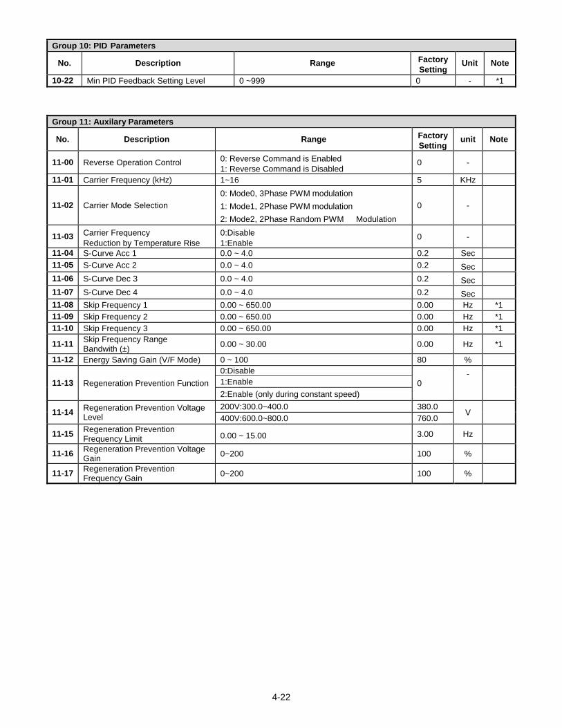
4-22
Group 10: PID Parameters
No. Description Range Factory
Setting Unit Note
10-22 Min PID Feedback Setting Level 0 ~999 0 - *1
Group 11: Auxilary Parameters
No. Description Range Factory
Setting unit Note
11-00 Reverse Operation Control 0: Reverse Command is Enabled
1: Reverse Command is Disabled 0 -
11-01 Carrier Frequency (kHz) 1~16 5 KHz
11-02 Carrier Mode Selection
0: Mode0, 3Phase PWM modulation
1: Mode1, 2Phase PWM modulation
2: Mode2, 2Phase Random PWM Modulation
0 -
11-03 Carrier Frequency
Reduction by Temperature Rise
0:Disable
1:Enable 0 -
11-04 S-Curve Acc 1 0.0 ~ 4.0 0.2 Sec
11-05 S-Curve Acc 2 0.0 ~ 4.0 0.2 Sec
11-06 S-Curve Dec 3 0.0 ~ 4.0 0.2 Sec
11-07 S-Curve Dec 4 0.0 ~ 4.0 0.2 Sec
11-08 Skip Frequency 1 0.00 ~ 650.00 0.00 Hz *1
11-09 Skip Frequency 2 0.00 ~ 650.00 0.00 Hz *1
11-10 Skip Frequency 3 0.00 ~ 650.00 0.00 Hz *1
11-11 Skip Frequency Range Bandwith (±)
0.00 ~ 30.00 0.00 Hz *1
11-12 Energy Saving Gain (V/F Mode) 0 ~ 100 80 %
11-13 Regeneration Prevention Function
0:Disable
0 -
1:Enable
2:Enable (only during constant speed)
11-14 Regeneration Prevention Voltage Level
200V:300.0~400.0 380.0 V
400V:600.0~800.0 760.0
11-15 Regeneration Prevention Frequency Limit 0.00 ~ 15.00 3.00 Hz
11-16 Regeneration Prevention Voltage Gain
0~200 100 %
11-17 Regeneration Prevention Frequency Gain
0~200 100 %
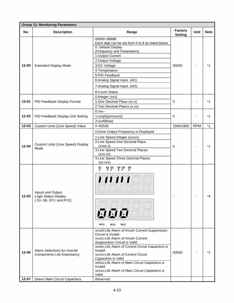
4-23
Group 12: Monitoring Parameters
No. Description Range Factory
Setting Unit Note
12-00 Extended Display Mode
00000~88888 Each digit can be set from 0 to 8 as listed below.
00000 - *1
0: Default Display (Frequency and Parameters)
1:Output Current
2:Output Voltage
3:DC Voltage
4:Temperature
5:PID Feedback
6:Analog Signal Input. (AI1)
7:Analog Signal Input. (AI2)
8:Count Status
12-01 PID Feedback Display Format
0:Integer (xxx)
0 - *1 1:One Decimal Place (xx.x)
2:Two Decimal Places (x.xx)
12-02 PID Feedback Display Unit Setting
0:xxx--
0 - *1 1:xxxpb(pressure)
2:xxxfl(flow)
12-03 Custom Units (Line Speed) Value 0~65535 1500/1800 RPM *1
12-04 Custom Units (Line Speed) Display Mode
0:Drive Output Frequency is Displayed
0 - *1
1:Line Speed.Integer.(xxxxx)
2:Line Speed.One Decimal Place. (xxxx.x)
3:Line Speed.Two Decimal Places (xxx.xx)
4:Line Speed.Three Decimal Places (xx.xxx)
12-05 Inputs and Output Logic Status Display ( S1~S6, RY1 and RY2)
S1 S2 S3 S4 S5 S6
RY1 RY2 PLC
- - *4
12-06
Alarm Selections for Inverter Components Life Expectancy
xxxx0:Life Alarm of Inrush Current Suppression Circuit is Invalid xxxx1:Life Alarm of Inrush Current Suppression Circuit is Valid
00000 - *1
xxx0x:Life Alarm of Control Circuit Capacitors is Invalid xxx1x:Life Alarm of Control Circuit Capacitors is Valid
xx0xx:Life Alarm of Main Circuit Capacitors is Invalid xx1xx:Life Alarm of Main Circuit Capacitors is Valid
12-07 Detect Main Circuit Capacitors Reserved
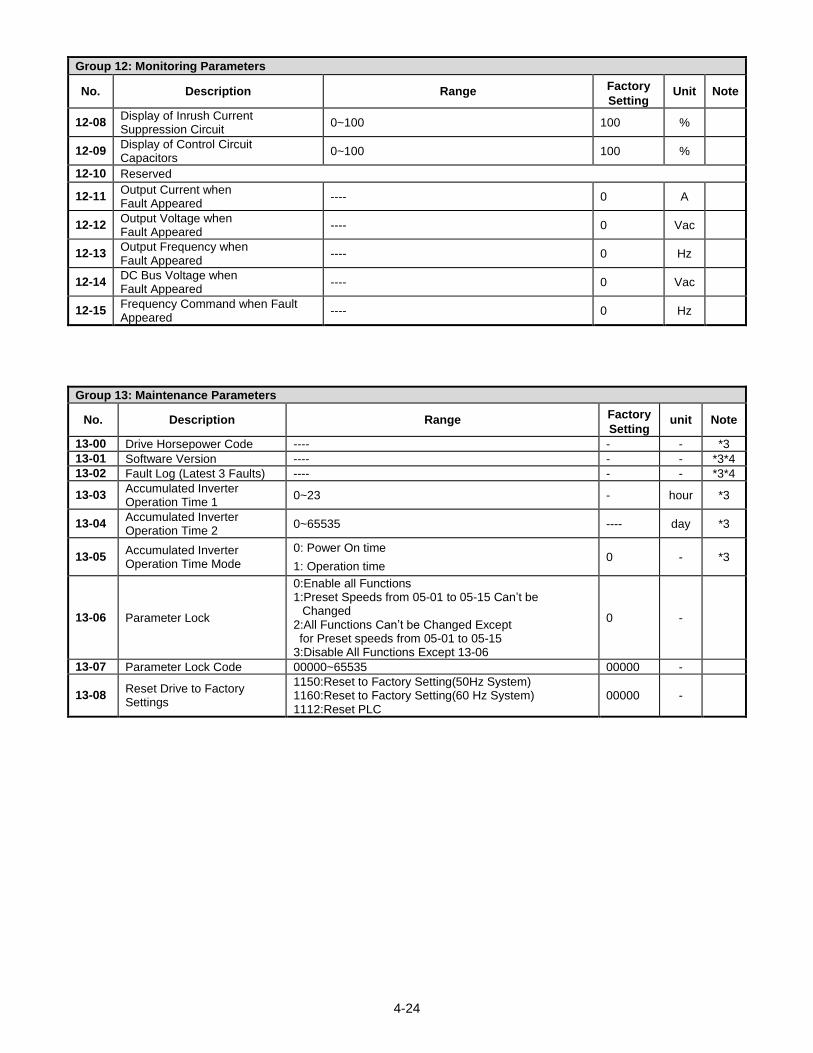
4-24
Group 12: Monitoring Parameters
No. Description Range Factory
Setting Unit Note
12-08 Display of Inrush Current Suppression Circuit
0~100 100 %
12-09 Display of Control Circuit Capacitors
0~100 100 %
12-10 Reserved
12-11 Output Current when Fault Appeared
---- 0 A
12-12 Output Voltage when Fault Appeared
---- 0 Vac
12-13 Output Frequency when Fault Appeared
---- 0 Hz
12-14 DC Bus Voltage when Fault Appeared
---- 0 Vac
12-15 Frequency Command when Fault Appeared
---- 0 Hz
Group 13: Maintenance Parameters
No. Description Range Factory
Setting unit Note
13-00 Drive Horsepower Code ---- - - *3
13-01 Software Version ---- - - *3*4
13-02 Fault Log (Latest 3 Faults) ---- - - *3*4
13-03 Accumulated Inverter Operation Time 1
0~23 - hour *3
13-04 Accumulated Inverter Operation Time 2
0~65535 ---- day *3
13-05 Accumulated Inverter Operation Time Mode
0: Power On time
1: Operation time 0 - *3
13-06 Parameter Lock
0:Enable all Functions 1:Preset Speeds from 05-01 to 05-15 Can’t be
Changed 2:All Functions Can’t be Changed Except for Preset speeds from 05-01 to 05-15 3:Disable All Functions Except 13-06
0 -
13-07 Parameter Lock Code 00000~65535 00000 -
13-08 Reset Drive to Factory Settings
1150:Reset to Factory Setting(50Hz System) 1160:Reset to Factory Setting(60 Hz System) 1112:Reset PLC
00000 -
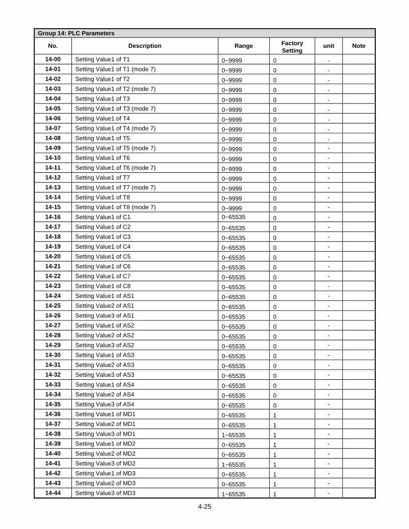
4-25
Group 14: PLC Parameters
No. Description Range Factory
Setting unit Note
14-00 Setting Value1 of T1 0~9999 0 -
14-01 Setting Value1 of T1 (mode 7) 0~9999 0 -
14-02 Setting Value1 of T2 0~9999 0 -
14-03 Setting Value1 of T2 (mode 7) 0~9999 0 -
14-04 Setting Value1 of T3 0~9999 0 -
14-05 Setting Value1 of T3 (mode 7) 0~9999 0 -
14-06 Setting Value1 of T4 0~9999 0 -
14-07 Setting Value1 of T4 (mode 7) 0~9999 0 -
14-08 Setting Value1 of T5 0~9999 0 -
14-09 Setting Value1 of T5 (mode 7) 0~9999 0 -
14-10 Setting Value1 of T6 0~9999 0 -
14-11 Setting Value1 of T6 (mode 7) 0~9999 0 -
14-12 Setting Value1 of T7 0~9999 0 -
14-13 Setting Value1 of T7 (mode 7) 0~9999 0 -
14-14 Setting Value1 of T8 0~9999 0 -
14-15 Setting Value1 of T8 (mode 7) 0~9999 0 -
14-16 Setting Value1 of C1 0~65535 0 -
14-17 Setting Value1 of C2 0~65535 0 -
14-18 Setting Value1 of C3 0~65535 0 -
14-19 Setting Value1 of C4 0~65535 0 -
14-20 Setting Value1 of C5 0~65535 0 -
14-21 Setting Value1 of C6 0~65535 0 -
14-22 Setting Value1 of C7 0~65535 0 -
14-23 Setting Value1 of C8 0~65535 0 -
14-24 Setting Value1 of AS1 0~65535 0 -
14-25 Setting Value2 of AS1 0~65535 0 -
14-26 Setting Value3 of AS1 0~65535 0 -
14-27 Setting Value1 of AS2 0~65535 0 -
14-28 Setting Value2 of AS2 0~65535 0 -
14-29 Setting Value3 of AS2 0~65535 0 -
14-30 Setting Value1 of AS3 0~65535 0 -
14-31 Setting Value2 of AS3 0~65535 0 -
14-32 Setting Value3 of AS3 0~65535 0 -
14-33 Setting Value1 of AS4 0~65535 0 -
14-34 Setting Value2 of AS4 0~65535 0 -
14-35 Setting Value3 of AS4 0~65535 0 -
14-36 Setting Value1 of MD1 0~65535 1 -
14-37 Setting Value2 of MD1 0~65535 1 -
14-38 Setting Value3 of MD1 1~65535 1 -
14-39 Setting Value1 of MD2 0~65535 1 -
14-40 Setting Value2 of MD2 0~65535 1 -
14-41 Setting Value3 of MD2 1~65535 1 -
14-42 Setting Value1 of MD3 0~65535 1 -
14-43 Setting Value2 of MD3 0~65535 1 -
14-44 Setting Value3 of MD3 1~65535 1 -
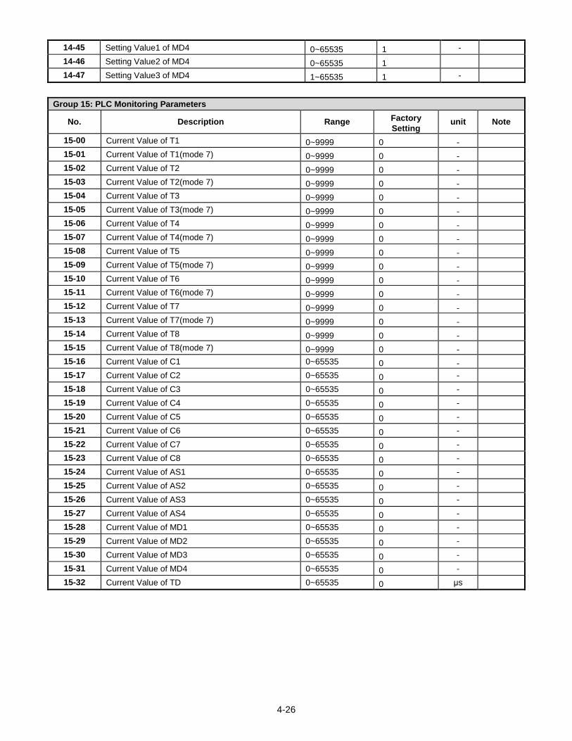
4-26
14-45 Setting Value1 of MD4 0~65535 1 -
14-46 Setting Value2 of MD4 0~65535 1
14-47 Setting Value3 of MD4 1~65535 1 -
Group 15: PLC Monitoring Parameters
No. Description Range Factory
Setting unit Note
15-00 Current Value of T1 0~9999 0 -
15-01 Current Value of T1(mode 7) 0~9999 0 -
15-02 Current Value of T2 0~9999 0 -
15-03 Current Value of T2(mode 7) 0~9999 0 -
15-04 Current Value of T3 0~9999 0 -
15-05 Current Value of T3(mode 7) 0~9999 0 -
15-06 Current Value of T4 0~9999 0 -
15-07 Current Value of T4(mode 7) 0~9999 0 -
15-08 Current Value of T5 0~9999 0 -
15-09 Current Value of T5(mode 7) 0~9999 0 -
15-10 Current Value of T6 0~9999 0 -
15-11 Current Value of T6(mode 7) 0~9999 0 -
15-12 Current Value of T7 0~9999 0 -
15-13 Current Value of T7(mode 7) 0~9999 0 -
15-14 Current Value of T8 0~9999 0 -
15-15 Current Value of T8(mode 7) 0~9999 0 -
15-16 Current Value of C1 0~65535 0 -
15-17 Current Value of C2 0~65535 0 -
15-18 Current Value of C3 0~65535 0 -
15-19 Current Value of C4 0~65535 0 -
15-20 Current Value of C5 0~65535 0 -
15-21 Current Value of C6 0~65535 0 -
15-22 Current Value of C7 0~65535 0 -
15-23 Current Value of C8 0~65535 0 -
15-24 Current Value of AS1 0~65535 0 -
15-25 Current Value of AS2 0~65535 0 -
15-26 Current Value of AS3 0~65535 0 -
15-27 Current Value of AS4 0~65535 0 -
15-28 Current Value of MD1 0~65535 0 -
15-29 Current Value of MD2 0~65535 0 -
15-30 Current Value of MD3 0~65535 0 -
15-31 Current Value of MD4 0~65535 0 -
15-32 Current Value of TD 0~65535 0 μs
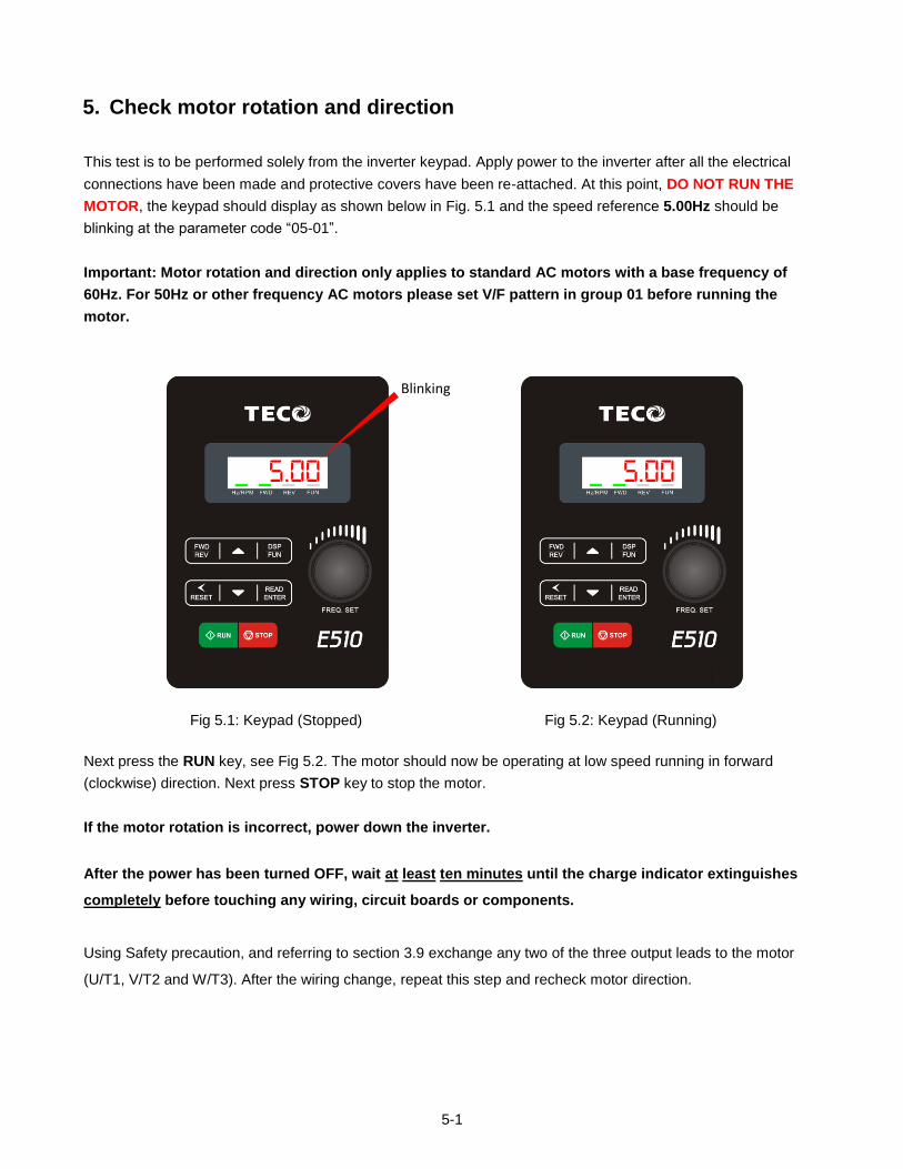
5-1
5. Check motor rotation and direction
This test is to be performed solely from the inverter keypad. Apply power to the inverter after all the electrical
connections have been made and protective covers have been re-attached. At this point, DO NOT RUN THE
MOTOR, the keypad should display as shown below in Fig. 5.1 and the speed reference 5.00Hz should be
blinking at the parameter code “05-01”.
Important: Motor rotation and direction only applies to standard AC motors with a base frequency of
60Hz. For 50Hz or other frequency AC motors please set V/F pattern in group 01 before running the
motor.
Blinking
5.00
5.00
Fig 5.1: Keypad (Stopped) Fig 5.2: Keypad (Running)
Next press the RUN key, see Fig 5.2. The motor should now be operating at low speed running in forward
(clockwise) direction. Next press STOP key to stop the motor.
If the motor rotation is incorrect, power down the inverter.
After the power has been turned OFF, wait at least ten minutes until the charge indicator extinguishes
completely before touching any wiring, circuit boards or components.
Using Safety precaution, and referring to section 3.9 exchange any two of the three output leads to the motor
(U/T1, V/T2 and W/T3). After the wiring change, repeat this step and recheck motor direction.
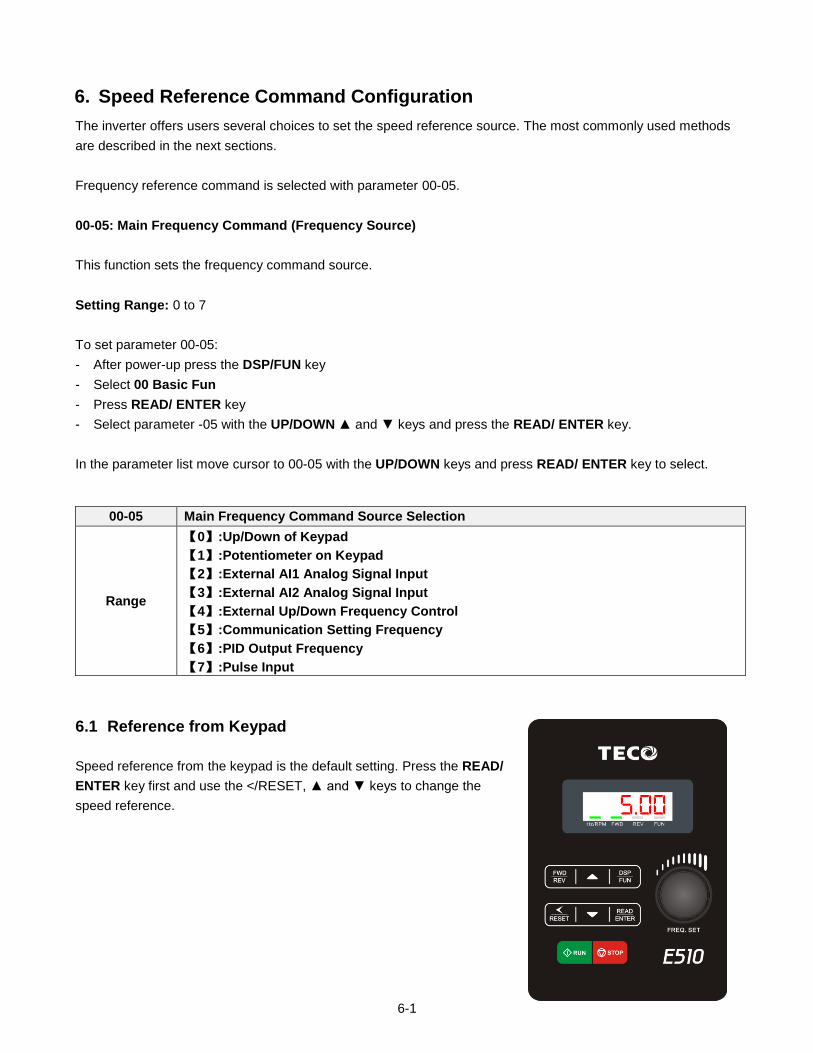
6-1
6. Speed Reference Command Configuration
The inverter offers users several choices to set the speed reference source. The most commonly used methods
are described in the next sections.
Frequency reference command is selected with parameter 00-05.
00-05: Main Frequency Command (Frequency Source)
This function sets the frequency command source.
Setting Range: 0 to 7
To set parameter 00-05:
- After power-up press the DSP/FUN key
- Select 00 Basic Fun
- Press READ/ ENTER key
- Select parameter -05 with the UP/DOWN and keys and press the READ/ ENTER key.
In the parameter list move cursor to 00-05 with the UP/DOWN keys and press READ/ ENTER key to select.
00-05 Main Frequency Command Source Selection
Range
【0】:Up/Down of Keypad
【1】:Potentiometer on Keypad
【2】:External AI1 Analog Signal Input
【3】:External AI2 Analog Signal Input
【4】:External Up/Down Frequency Control
【5】:Communication Setting Frequency
【6】:PID Output Frequency
【7】:Pulse Input
6.1 Reference from Keypad
Speed reference from the keypad is the default setting. Press the READ/
ENTER key first and use the </RESET, and keys to change the
speed reference. 5.00
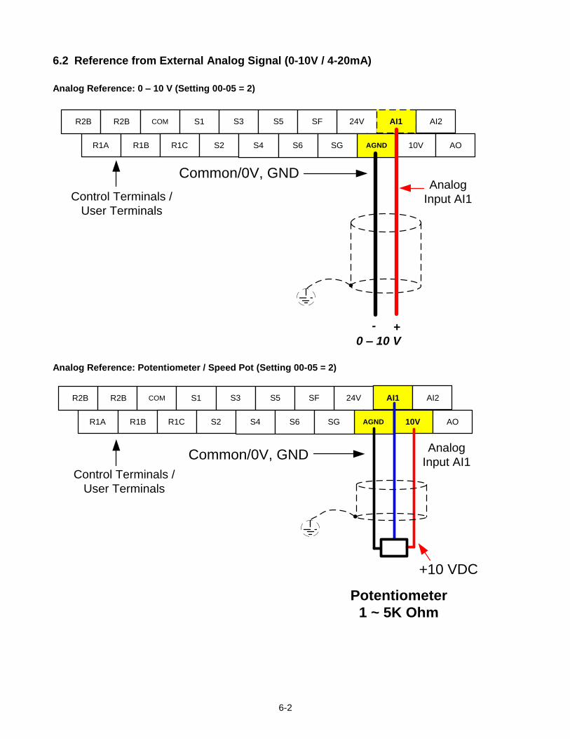
6-2
6.2 Reference from External Analog Signal (0-10V / 4-20mA)
Analog Reference: 0 – 10 V (Setting 00-05 = 2)
24V AI1
AGND
0 – 10 V+-
Analog
Input AI1
Common/0V, GND
Control Terminals /
User Terminals
R1A R1B 10V AO
R2B R2B COM S1 S3 S5 SF AI2
R1C S2 S4 S6 SG
Analog Reference: Potentiometer / Speed Pot (Setting 00-05 = 2)
24V AI1
AGNDR1A R1B 10V AO
R2B R2B COM S1 S3 S5 SF AI2
R1C S2 S4 S6 SG
Control Terminals /
User Terminals
Potentiometer
1 ~ 5K Ohm
+10 VDC
Common/0V, GNDAnalog
Input AI1
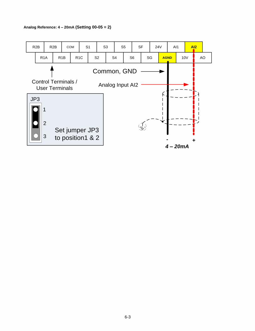
6-3
Analog Reference: 4 – 20mA (Setting 00-05 = 2)
24V AI1
AGNDR1A R1B 10V AO
R2B R2B COM S1 S3 S5 SF AI2
R1C S2 S4 S6 SG
4 – 20mA+-
Analog Input AI2
Common, GND
Control Terminals /
User Terminals
Set jumper JP3
to position1 & 2
JP3
1
2
3
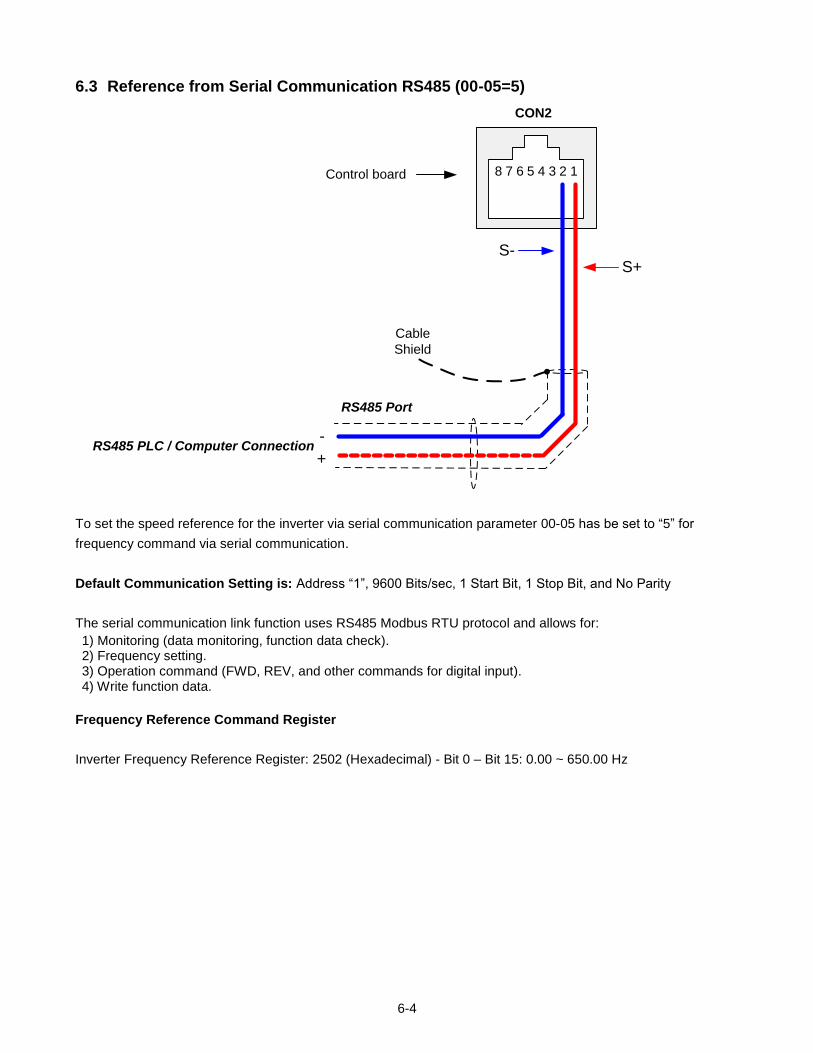
6-4
6.3 Reference from Serial Communication RS485 (00-05=5)
RS485 PLC / Computer Connection-
+
S-S+
Cable
Shield
RS485 Port
8 7 6 5 4 3 2 1
CON2
Control board
To set the speed reference for the inverter via serial communication parameter 00-05 has be set to “5” for
frequency command via serial communication.
Default Communication Setting is: Address “1”, 9600 Bits/sec, 1 Start Bit, 1 Stop Bit, and No Parity
The serial communication link function uses RS485 Modbus RTU protocol and allows for:
1) Monitoring (data monitoring, function data check). 2) Frequency setting. 3) Operation command (FWD, REV, and other commands for digital input). 4) Write function data.
Frequency Reference Command Register
Inverter Frequency Reference Register: 2502 (Hexadecimal) - Bit 0 – Bit 15: 0.00 ~ 650.00 Hz
6-5
Examples:
Frequency Reference Command: 10.00 Hz (Inverter Node Address: 01)
Command String (hexadecimal): 01 06 25 02 03 E8 23 B8
To set the frequency reference to 10.00, a value of ‘1000’ (03E8h) has to be send to the inverter.
Frequency Reference Command: 30.00 Hz (Inverter Node Address: 01)
Command String (hexadecimal): 01 06 25 02 0B B8 24 44
To set the frequency reference to 30.00, a value of ‘3000’ (0BB8h) has to be send to the inverter.
Frequency Reference Command: 60.00 Hz (Inverter Node Address: 01)
Command String (hexadecimal): 01 06 25 02 17 70 2D 12
To set the frequency reference to 60.00, a value of ‘6000’ (1770h) has to be send to the inverter
Note: The last 2 bytes of the command strings consist of a CRC16 checksum, please refer to section 4.5 of the
instruction manual for additional information.
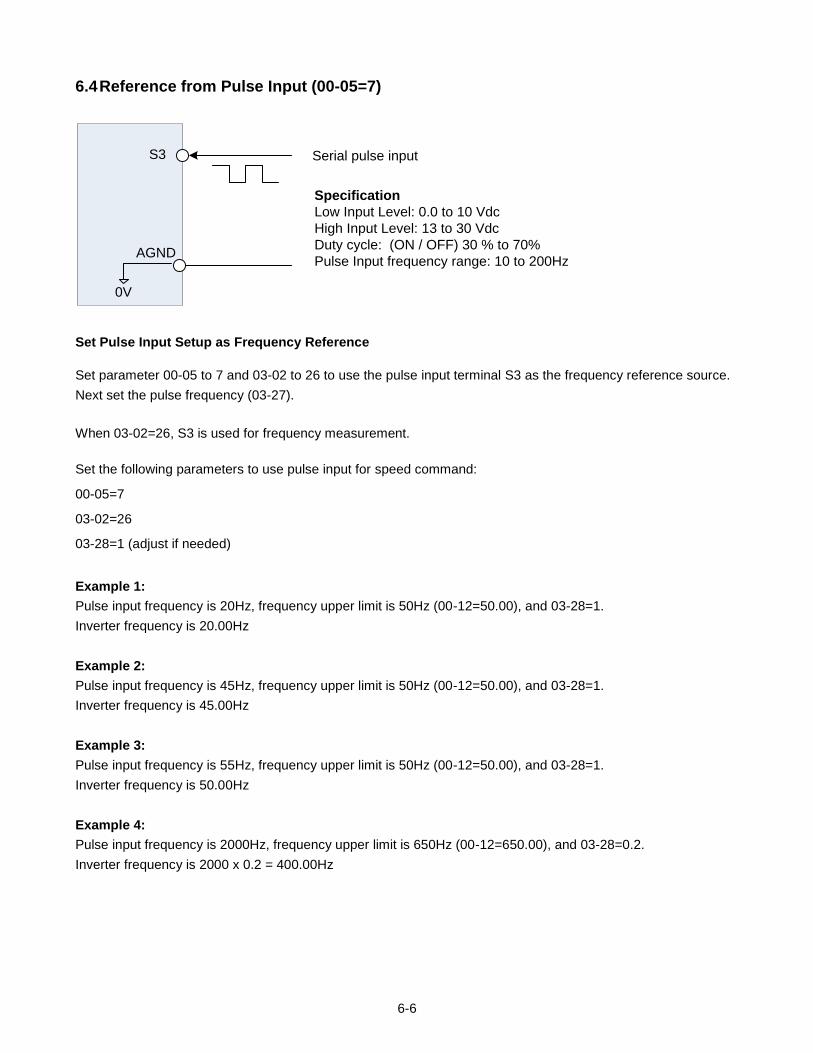
6-6
6.4 Reference from Pulse Input (00-05=7)
S3
AGND
0V
Serial pulse input
Specification
Low Input Level: 0.0 to 10 Vdc
High Input Level: 13 to 30 Vdc
Duty cycle: (ON / OFF) 30 % to 70%
Pulse Input frequency range: 10 to 200Hz
Set Pulse Input Setup as Frequency Reference
Set parameter 00-05 to 7 and 03-02 to 26 to use the pulse input terminal S3 as the frequency reference source.
Next set the pulse frequency (03-27).
When 03-02=26, S3 is used for frequency measurement.
Set the following parameters to use pulse input for speed command:
00-05=7
03-02=26
03-28=1 (adjust if needed)
Example 1:
Pulse input frequency is 20Hz, frequency upper limit is 50Hz (00-12=50.00), and 03-28=1.
Inverter frequency is 20.00Hz
Example 2:
Pulse input frequency is 45Hz, frequency upper limit is 50Hz (00-12=50.00), and 03-28=1.
Inverter frequency is 45.00Hz
Example 3:
Pulse input frequency is 55Hz, frequency upper limit is 50Hz (00-12=50.00), and 03-28=1.
Inverter frequency is 50.00Hz
Example 4:
Pulse input frequency is 2000Hz, frequency upper limit is 650Hz (00-12=650.00), and 03-28=0.2.
Inverter frequency is 2000 x 0.2 = 400.00Hz
6-7
6.5 Change Frequency Unit from Hz to rpm
12-03 Custom Units (Line Speed) Display Mode
Range 【0~65535】Rpm
Set motor rated RPM for the inverter to display the actual motor speed based on the output frequency.
Motor synchronous speed = 120 x Rated frequency ÷ Number of poles.
12- 04 Custom Units (Line Speed) Display Mode
Range
【0】:Drive Output Frequency is Displayed
【1】:Line Speed is Displayed in Integer (xxxxx)
【2】:Line Speed is Displayed with One Decimal Place (xxxx.x)
【3】:Line Speed is Displayed with Two Decimal Places (xxx.xx)
【4】:Line Speed is Displayed with Three Decimal Places (xx.xxx)
Set parameter 12-04 to a value greater than 0 to display motor speed.
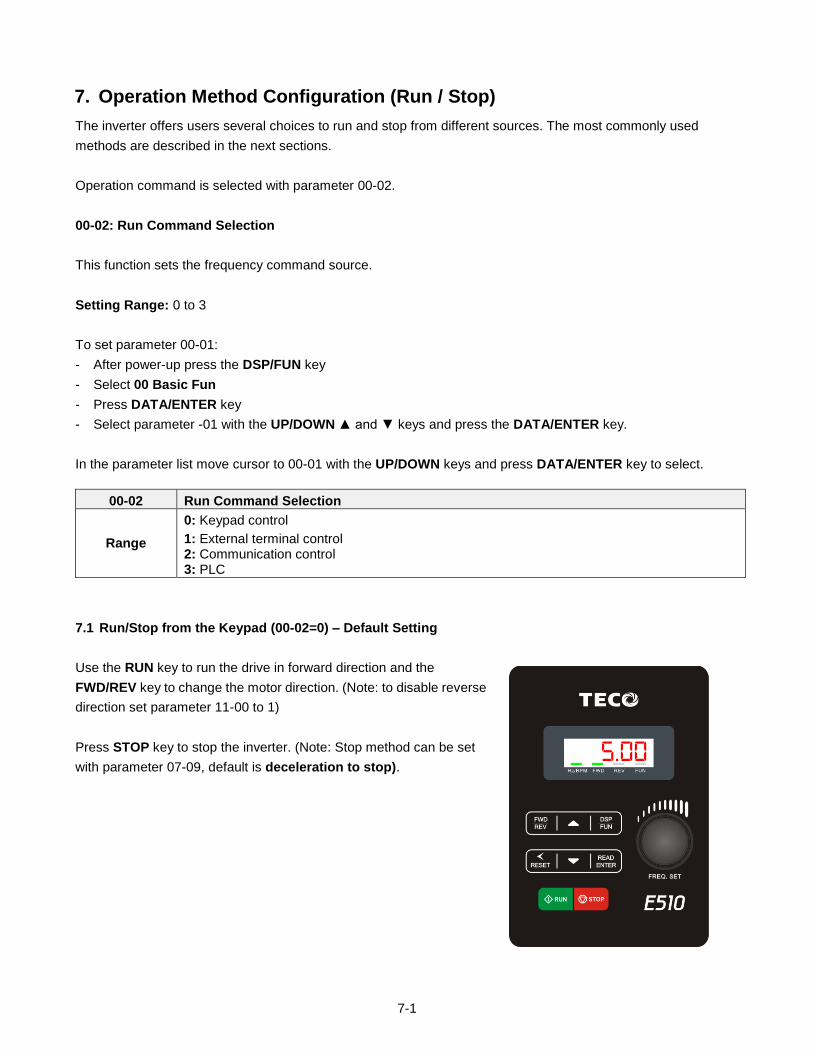
7-1
7. Operation Method Configuration (Run / Stop)
The inverter offers users several choices to run and stop from different sources. The most commonly used
methods are described in the next sections.
Operation command is selected with parameter 00-02.
00-02: Run Command Selection
This function sets the frequency command source.
Setting Range: 0 to 3
To set parameter 00-01:
- After power-up press the DSP/FUN key
- Select 00 Basic Fun
- Press DATA/ENTER key
- Select parameter -01 with the UP/DOWN and keys and press the DATA/ENTER key.
In the parameter list move cursor to 00-01 with the UP/DOWN keys and press DATA/ENTER key to select.
00-02 Run Command Selection
Range
0: Keypad control
1: External terminal control 2: Communication control 3: PLC
7.1 Run/Stop from the Keypad (00-02=0) – Default Setting
Use the RUN key to run the drive in forward direction and the
FWD/REV key to change the motor direction. (Note: to disable reverse
direction set parameter 11-00 to 1)
Press STOP key to stop the inverter. (Note: Stop method can be set
with parameter 07-09, default is deceleration to stop).
5.00
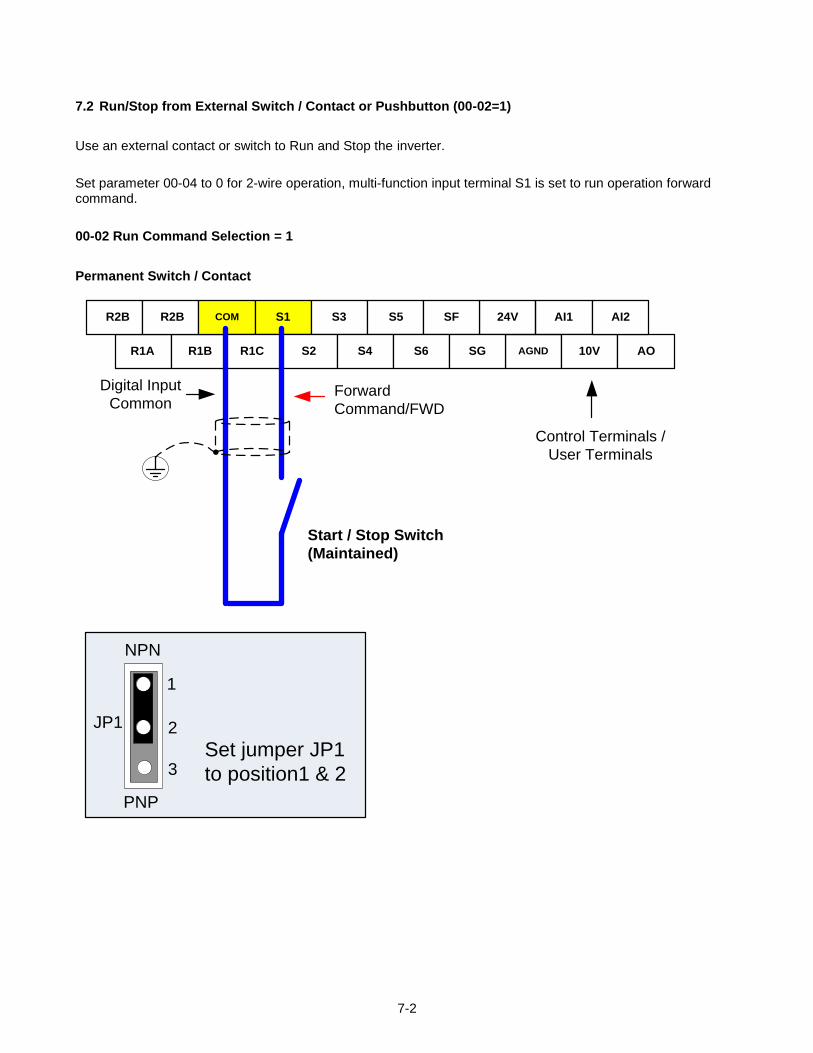
7-2
7.2 Run/Stop from External Switch / Contact or Pushbutton (00-02=1)
Use an external contact or switch to Run and Stop the inverter.
Set parameter 00-04 to 0 for 2-wire operation, multi-function input terminal S1 is set to run operation forward command.
00-02 Run Command Selection = 1
Permanent Switch / Contact
24V AI1
AGNDR1A R1B 10V AO
R2B R2B COM S1 S3 S5 SF AI2
R1C S2 S4 S6 SG
Start / Stop Switch
(Maintained)
Forward
Command/FWD
Digital Input
Common
Control Terminals /
User Terminals
Set jumper JP1
to position1 & 2
JP1
1
2
3
NPN
PNP
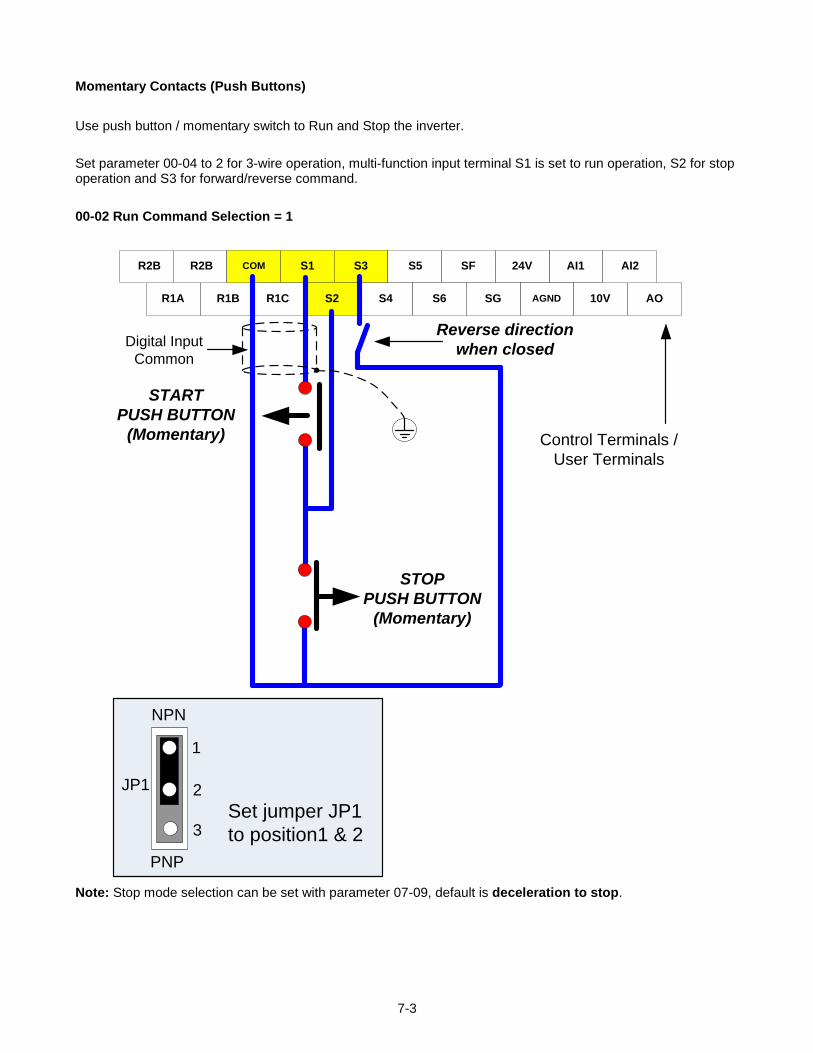
7-3
Momentary Contacts (Push Buttons)
Use push button / momentary switch to Run and Stop the inverter.
Set parameter 00-04 to 2 for 3-wire operation, multi-function input terminal S1 is set to run operation, S2 for stop operation and S3 for forward/reverse command.
00-02 Run Command Selection = 1
24V AI1
AGNDR1A R1B 10V AO
R2B R2B COM S1 S3 S5 SF AI2
R1C S2 S4 S6 SG
START
PUSH BUTTON
(Momentary)
STOP
PUSH BUTTON
(Momentary)
Control Terminals /
User Terminals
Reverse direction
when closed
Set jumper JP1
to position1 & 2
JP1
1
2
3
NPN
PNP
Digital Input
Common
Note: Stop mode selection can be set with parameter 07-09, default is deceleration to stop.
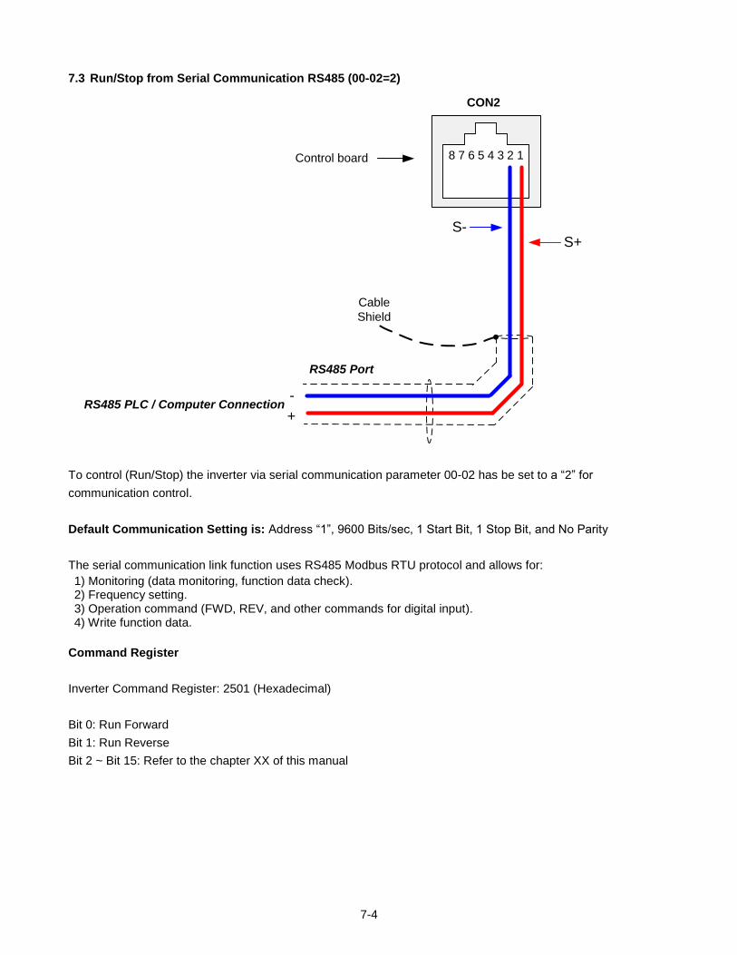
7-4
7.3 Run/Stop from Serial Communication RS485 (00-02=2)
RS485 PLC / Computer Connection-
+
S-S+
Cable
Shield
RS485 Port
8 7 6 5 4 3 2 1
CON2
Control board
To control (Run/Stop) the inverter via serial communication parameter 00-02 has be set to a “2” for
communication control.
Default Communication Setting is: Address “1”, 9600 Bits/sec, 1 Start Bit, 1 Stop Bit, and No Parity
The serial communication link function uses RS485 Modbus RTU protocol and allows for:
1) Monitoring (data monitoring, function data check). 2) Frequency setting. 3) Operation command (FWD, REV, and other commands for digital input). 4) Write function data.
Command Register
Inverter Command Register: 2501 (Hexadecimal)
Bit 0: Run Forward
Bit 1: Run Reverse
Bit 2 ~ Bit 15: Refer to the chapter XX of this manual
7-5
Examples:
Run Forward Command (Inverter Address: 01)
Command String (hexadecimal): 01 06 25 01 00 01 12 C6
Run Reverse Command (Inverter Address: 01)
Command String (hexadecimal): 01 06 25 01 00 03 93 07
Stop Command (Inverter Address: 01)
Command String (hexadecimal): 01 06 25 01 00 00 D3 06
Note: The last 2 bytes of the command strings consist of a CRC16 checksum, please refer to section 4.5 of the
instruction manual for additional information.
8-1
8. Motor and Application Specific Settings
It is essential that before running the motor, the motor nameplate data matches the motor data in the inverter.
8.1 Set Motor Nameplate Data (02-01, 02-05)
02-05 Motor Rated Power
The nominal motor rated capacity is set at the factory. Please verify that the motor name plate data matches the motor rated capacity shown in parameter 02-05. The setting should only be changed when driving a motor with a different capacity. Range: 0.1 to 37.0 kW (1HP = 0.746 kW)
To set parameter 02-05:
- After power-up press the DSP/FUN key
- Select 02 Motor Parameter
- Press READ/ ENTER key
- Select parameter -01 with the UP/DOWN and keys and press the READ/ ENTER key.
Default values vary based on the inverter model.
02-01 Motor Rated Current
The motor rated current is set at the factory based on the inverter model. Enter the motor rated current from the motor nameplate if it does not match the value shown in parameter 02-01.
Setting range: 0.2 to 100.00A
To set parameter 02-01:
- After power-up press the DSP/FUN key
- Select 02 Motor Parameter
- Press READ/ ENTER key
- Select parameter -01 with the UP/DOWN and keys and press the READ/ ENTER key.
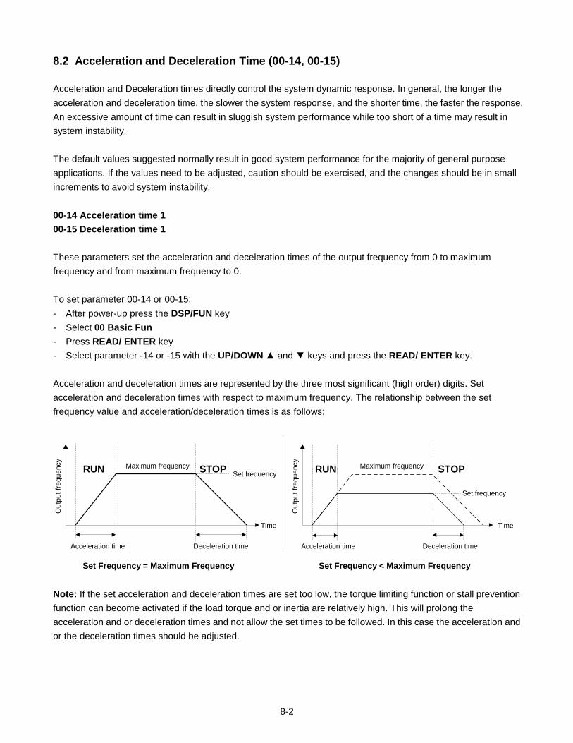
8-2
8.2 Acceleration and Deceleration Time (00-14, 00-15)
Acceleration and Deceleration times directly control the system dynamic response. In general, the longer the
acceleration and deceleration time, the slower the system response, and the shorter time, the faster the response.
An excessive amount of time can result in sluggish system performance while too short of a time may result in
system instability.
The default values suggested normally result in good system performance for the majority of general purpose
applications. If the values need to be adjusted, caution should be exercised, and the changes should be in small
increments to avoid system instability.
00-14 Acceleration time 1
00-15 Deceleration time 1
These parameters set the acceleration and deceleration times of the output frequency from 0 to maximum
frequency and from maximum frequency to 0.
To set parameter 00-14 or 00-15:
- After power-up press the DSP/FUN key
- Select 00 Basic Fun
- Press READ/ ENTER key
- Select parameter -14 or -15 with the UP/DOWN and keys and press the READ/ ENTER key.
Acceleration and deceleration times are represented by the three most significant (high order) digits. Set
acceleration and deceleration times with respect to maximum frequency. The relationship between the set
frequency value and acceleration/deceleration times is as follows:
Ou
tpu
t fr
eq
ue
ncy
Acceleration time
Set frequency
Time
Deceleration time
Maximum frequency
Ou
tpu
t fr
eq
ue
ncy
Acceleration time
Set frequency
Time
Deceleration time
Maximum frequency RUN STOPRUN STOP
Set Frequency = Maximum Frequency Set Frequency < Maximum Frequency
Note: If the set acceleration and deceleration times are set too low, the torque limiting function or stall prevention
function can become activated if the load torque and or inertia are relatively high. This will prolong the
acceleration and or deceleration times and not allow the set times to be followed. In this case the acceleration and
or the deceleration times should be adjusted.
8-3
8.3 Torque Boost (V/f Curve Modification) (01-10)
This parameter sets the relationship between output frequency and output voltage. Constant torque applications
have the same torque requirements at low speed as well as at high speed.
Initial Setup
For Variable Torque / Normal Duty applications set parameter 01-10 to an initial value of 0.5.
For Constant Torque / Heavy Duty applications set parameter 01-10 to an initial value of 1.0.
01-10 Torque compensation gain
This parameter sets the torque boost for motor 1.
Setting range: 0.0 to 10.0
To set parameter 01-10:
- After power-up press the DSP/FUN key
- Select 01 V/F Pattern
- Press READ/ ENTER key
- Select parameter -10 with the UP/DOWN and keys and press the READ/ ENTER key.
Increase value when:
The wiring between the inverter and the motor very too long
The motor size is smaller than the inverter size
Note: Gradually increase the torque compensation value and make sure the output current does not exceed inverter rated current.
Reduce value when:
Experiencing motor vibration
Over Current Fault
Overload Fault
Important: Confirm that the output current at low speed does not exceed the rated output current of the inverter.
Warning: A larger than required torque compensation gain value creates over-excitation at low
speeds, continued operation may cause the motor to overheat. Check the characteristics of the
motor for additional information.
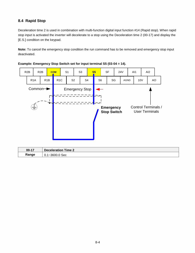
8-4
8.4 Rapid Stop
Deceleration time 2 is used in combination with multi-function digital input function #14 (Rapid stop). When rapid
stop input is activated the inverter will decelerate to a stop using the Deceleration time 2 (00-17) and display the
[E.S.] condition on the keypad.
Note: To cancel the emergency stop condition the run command has to be removed and emergency stop input
deactivated.
Example: Emergency Stop Switch set for input terminal S5 (03-04 = 14).
24V AI1
AGNDR1A R1B 10V AO
R2B R2B COM S1 S3 S5 SF AI2
R1C S2 S4 S6 SG
Emergency
Stop Switch
Emergency StopCommon
Control Terminals /
User Terminals
00-17 Deceleration Time 2
Range 0.1~3600.0 Sec
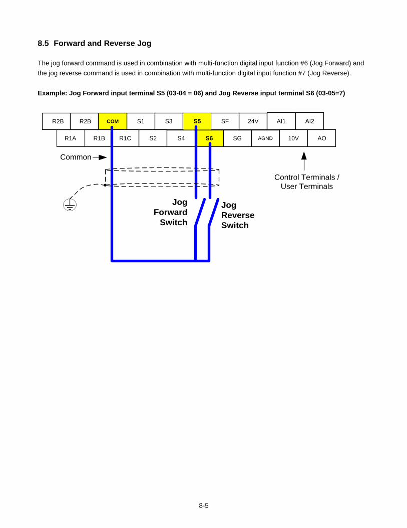
8-5
8.5 Forward and Reverse Jog
The jog forward command is used in combination with multi-function digital input function #6 (Jog Forward) and
the jog reverse command is used in combination with multi-function digital input function #7 (Jog Reverse).
Example: Jog Forward input terminal S5 (03-04 = 06) and Jog Reverse input terminal S6 (03-05=7)
24V AI1
AGNDR1A R1B 10V AO
R2B R2B COM S1 S3 S5 SF AI2
R1C S2 S4 S6 SG
Jog
Reverse
Switch
Common
Control Terminals /
User Terminals
Jog
Forward
Switch
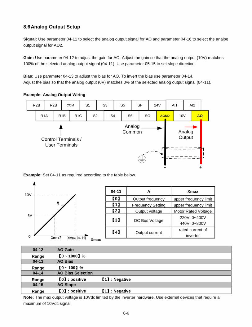
8-6
8.6 Analog Output Setup
Signal: Use parameter 04-11 to select the analog output signal for AO and parameter 04-16 to select the analog
output signal for AO2.
Gain: Use parameter 04-12 to adjust the gain for AO. Adjust the gain so that the analog output (10V) matches
100% of the selected analog output signal (04-11). Use parameter 05-15 to set slope direction.
Bias: Use parameter 04-13 to adjust the bias for AO. To invert the bias use parameter 04-14.
Adjust the bias so that the analog output (0V) matches 0% of the selected analog output signal (04-11).
Example: Analog Output Wiring
24V AI1
AGNDR1A R1B 10V AO
R2B R2B COM S1 S3 S5 SF AI2
R1C S2 S4 S6 SG
Analog
Common
Control Terminals /
User Terminals
Analog
Output
+-
Example: Set 04-11 as required according to the table below.
0
10V
Xmax
A
Xmax( 04-11)Xmax/2
5 V
04-12 AO Gain
Range 【0 ~ 1000】%
04-13 AO Bias
Range 【0 ~ 100】%
04-14 AO Bias Selection
Range 【0】: positive 【1】: Negative
04-15 AO Slope
Range 【0】: positive 【1】: Negative
Note: The max output voltage is 10Vdc limited by the inverter hardware. Use external devices that require a
maximum of 10Vdc signal.
04-11 A Xmax
【0】 Output frequency upper frequency limit
【1】 Frequency Setting upper frequency limit
【2】 Output voltage Motor Rated Voltage
【3】 DC Bus Voltage 220V: 0~400V
440V: 0~800V
【4】 Output current rated current of
inverter
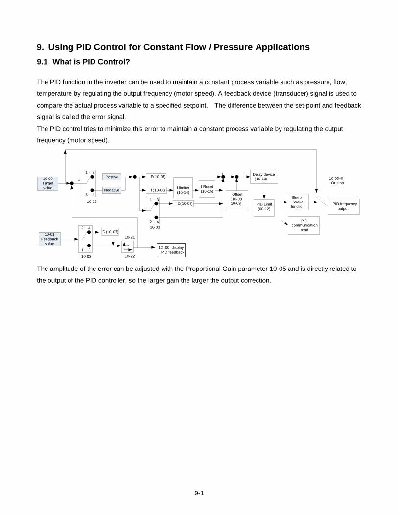
9-1
9. Using PID Control for Constant Flow / Pressure Applications
9.1 What is PID Control?
The PID function in the inverter can be used to maintain a constant process variable such as pressure, flow,
temperature by regulating the output frequency (motor speed). A feedback device (transducer) signal is used to
compare the actual process variable to a specified setpoint. The difference between the set-point and feedback
signal is called the error signal.
The PID control tries to minimize this error to maintain a constant process variable by regulating the output
frequency (motor speed).
1、 2
3、4
Postive
Negative
10-03
P(10-05)
I (10-06)
+
10-03
-
10-00
Target
value
10-01
Feedback
value
10-21
10-22
12 - 00 display
PID feedback
10-03=0
Or stop
I limiter
(10-14)
1、3
2、4
D(10-07)
+
+
Offset
(10-08
10-09)
+
Delay device
(10-10)
PID
communication
read
Sleep
Wake
functionPID frequency
output
2、4
1、3
10-03
I Reset
(10-15)
PID Limit
(00-12)
D (10-07)
The amplitude of the error can be adjusted with the Proportional Gain parameter 10-05 and is directly related to
the output of the PID controller, so the larger gain the larger the output correction.
9-2
Example 1: Example 2:
Gain = 1.0 Gain = 2.0
Set-Point = 80% Set-Point = 80%
Feedback = 78% Feedback = 78%
Error = Set-point - Feedback = 2% Error = Set-point - Feedback = 2%
Control Error = Gain x Error = 2% Control Error = Gain x Error = 4%
Please note that an excessive gain can make the system unstable and oscillation may occur.
The response time of the system can be adjusted with the Integral Gain set by parameter 10-06. Increasing the
Integral Time will make the system less responsive and decreasing the Integral Gain Time will increase response
but may result in instability of the total system.
Slowing the system down too much may be unsatisfactory for the process. The end result is that these two
parameters in conjunction with the acceleration (00-14) and deceleration (00-15) times are adjusted to achieve
optimum performance for a particular application.
For typical fan and pump applications a Proportional Gain (10-05) of 2.0 and an Integral Time (10-06) of 5.0
sec. is recommended.
10-03 PID control mode
PID control can be enabled by setting parameter 00-05 to 6 and parameter 10-03 to a value greater than 0.
10- 03 PID Mode Selection
Range
【0】:PID Function disabled
【1】:FWD Characteristic. Deviation is D-controlled
【2】:FWD Characteristic. Feedback is D-controlled
【3】:REV Characteristic. Deviation is D-controlled
【4】:REV Characteristic. Feedback is D-controlled
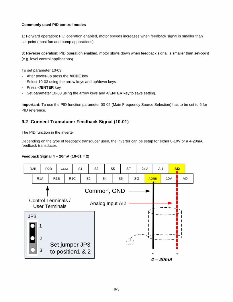
9-3
Commonly used PID control modes
1: Forward operation: PID operation enabled, motor speeds increases when feedback signal is smaller than
set-point (most fan and pump applications)
3: Reverse operation: PID operation enabled, motor slows down when feedback signal is smaller than set-point
(e.g. level control applications)
To set parameter 10-03:
- After power-up press the MODE key
- Select 10-03 using the arrow keys and up/down keys
- Press </ENTER key
- Set parameter 10-03 using the arrow keys and </ENTER key to save setting.
Important: To use the PID function parameter 00-05 (Main Frequency Source Selection) has to be set to 6 for
PID reference.
9.2 Connect Transducer Feedback Signal (10-01)
The PID function in the inverter
Depending on the type of feedback transducer used, the inverter can be setup for either 0-10V or a 4-20mA feedback transducer.
Feedback Signal 4 – 20mA (10-01 = 2)
24V AI1
AGNDR1A R1B 10V AO
R2B R2B COM S1 S3 S5 SF AI2
R1C S2 S4 S6 SG
4 – 20mA+-
Analog Input AI2
Common, GND
Control Terminals /
User Terminals
Set jumper JP3
to position1 & 2
JP3
1
2
3
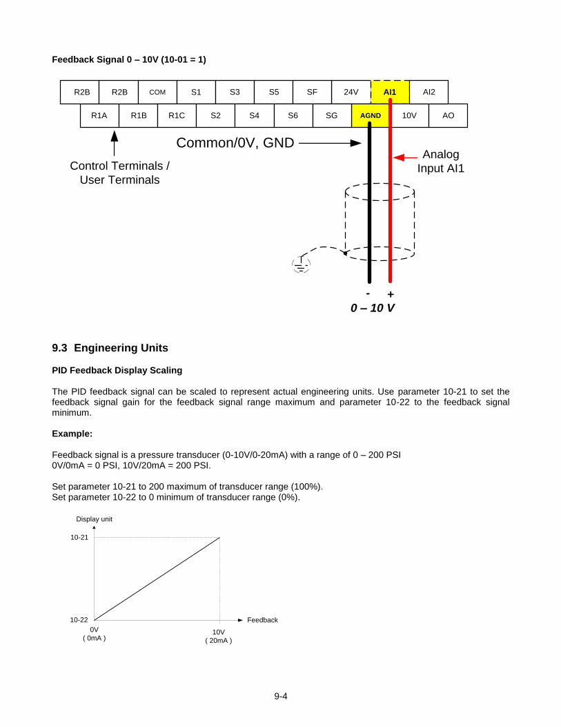
9-4
Feedback Signal 0 – 10V (10-01 = 1)
24V AI1
AGND
0 – 10 V+-
Analog
Input AI1
Common/0V, GND
Control Terminals /
User Terminals
R1A R1B 10V AO
R2B R2B COM S1 S3 S5 SF AI2
R1C S2 S4 S6 SG
9.3 Engineering Units PID Feedback Display Scaling
The PID feedback signal can be scaled to represent actual engineering units. Use parameter 10-21 to set the feedback signal gain for the feedback signal range maximum and parameter 10-22 to the feedback signal minimum. Example: Feedback signal is a pressure transducer (0-10V/0-20mA) with a range of 0 – 200 PSI 0V/0mA = 0 PSI, 10V/20mA = 200 PSI. Set parameter 10-21 to 200 maximum of transducer range (100%). Set parameter 10-22 to 0 minimum of transducer range (0%).
Feedback
10V
( 20mA )
0V
( 0mA )
10-21
10-22
Display unit
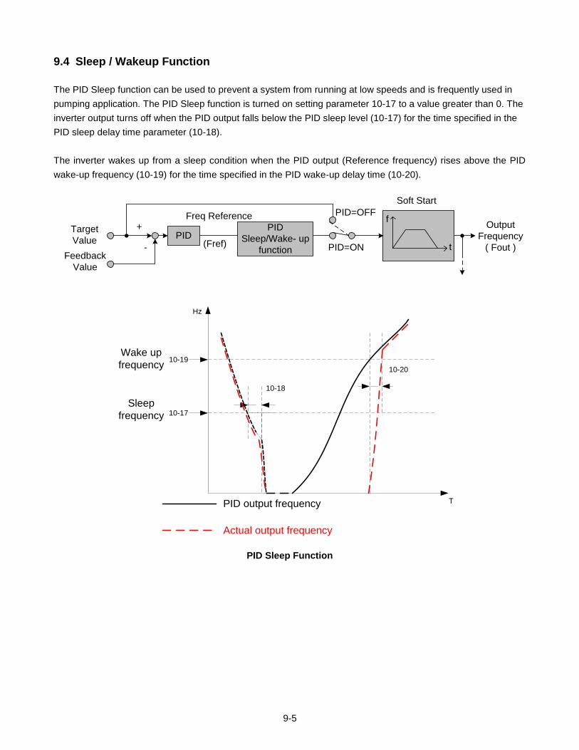
9-5
9.4 Sleep / Wakeup Function
The PID Sleep function can be used to prevent a system from running at low speeds and is frequently used in
pumping application. The PID Sleep function is turned on setting parameter 10-17 to a value greater than 0. The
inverter output turns off when the PID output falls below the PID sleep level (10-17) for the time specified in the
PID sleep delay time parameter (10-18).
The inverter wakes up from a sleep condition when the PID output (Reference frequency) rises above the PID
wake-up frequency (10-19) for the time specified in the PID wake-up delay time (10-20).
PID Target
Value
Feedback
Value
+
-
PID=OFF
PID=ON
f
Soft Start
Output
Frequency
( Fout )
PID
Sleep/Wake- up
function(Fref)
Freq Reference
t
10-18
Hz
T
10-19
10-17
10-20
Wake up
frequency
Sleep
frequency
PID output frequency
Actual output frequency
PID Sleep Function
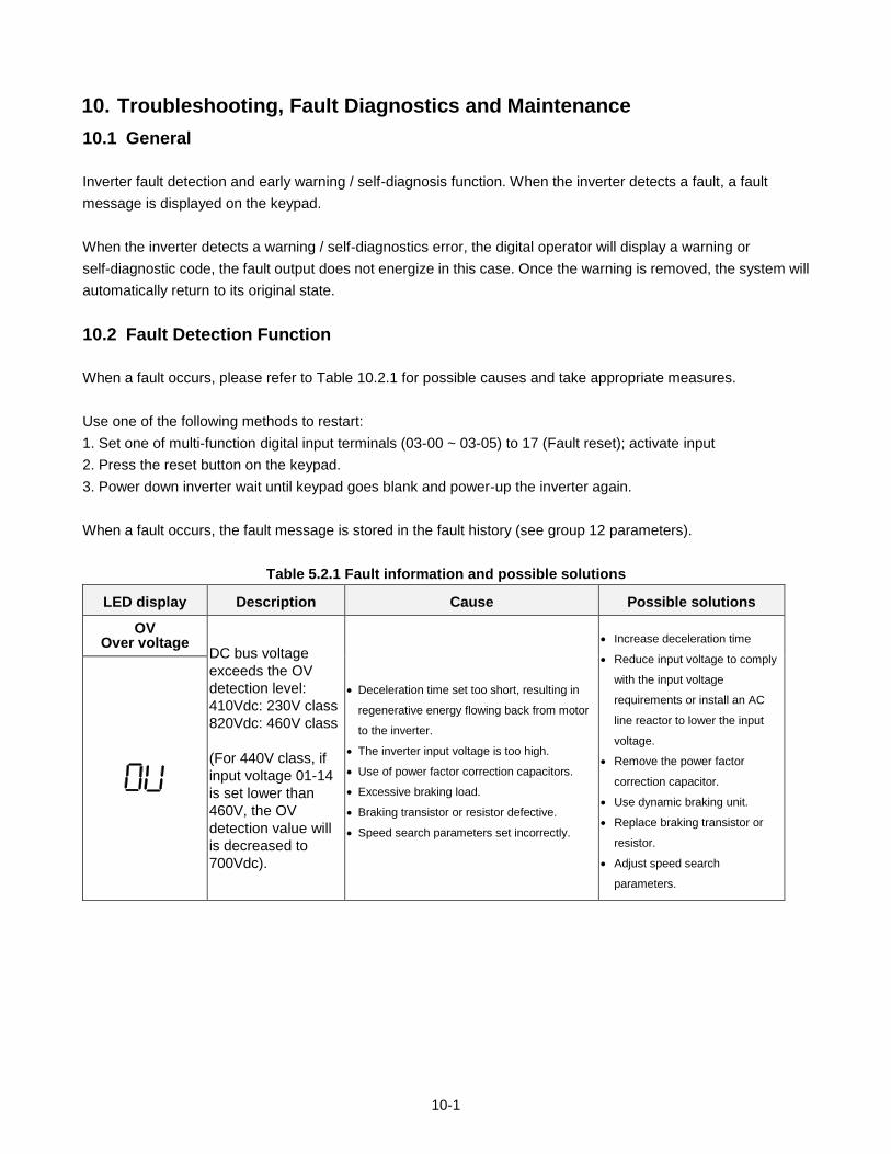
10-1
10. Troubleshooting, Fault Diagnostics and Maintenance
10.1 General
Inverter fault detection and early warning / self-diagnosis function. When the inverter detects a fault, a fault
message is displayed on the keypad.
When the inverter detects a warning / self-diagnostics error, the digital operator will display a warning or
self-diagnostic code, the fault output does not energize in this case. Once the warning is removed, the system will
automatically return to its original state.
10.2 Fault Detection Function
When a fault occurs, please refer to Table 10.2.1 for possible causes and take appropriate measures.
Use one of the following methods to restart:
1. Set one of multi-function digital input terminals (03-00 ~ 03-05) to 17 (Fault reset); activate input
2. Press the reset button on the keypad.
3. Power down inverter wait until keypad goes blank and power-up the inverter again.
When a fault occurs, the fault message is stored in the fault history (see group 12 parameters).
Table 5.2.1 Fault information and possible solutions
LED display Description Cause Possible solutions
OV Over voltage
DC bus voltage
exceeds the OV
detection level:
410Vdc: 230V class
820Vdc: 460V class
(For 440V class, if
input voltage 01-14
is set lower than
460V, the OV
detection value will
is decreased to
700Vdc).
Deceleration time set too short, resulting in
regenerative energy flowing back from motor
to the inverter.
The inverter input voltage is too high.
Use of power factor correction capacitors.
Excessive braking load.
Braking transistor or resistor defective.
Speed search parameters set incorrectly.
Increase deceleration time
Reduce input voltage to comply
with the input voltage
requirements or install an AC
line reactor to lower the input
voltage.
Remove the power factor
correction capacitor.
Use dynamic braking unit.
Replace braking transistor or
resistor.
Adjust speed search
parameters.
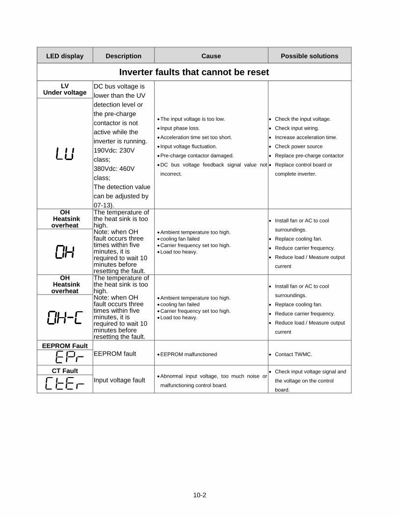
10-2
LED display Description Cause Possible solutions
Inverter faults that cannot be reset
LV Under voltage
DC bus voltage is
lower than the UV
detection level or
the pre-charge
contactor is not
active while the
inverter is running.
190Vdc: 230V
class;
380Vdc: 460V
class;
The detection value
can be adjusted by
07-13).
The input voltage is too low.
Input phase loss.
Acceleration time set too short.
Input voltage fluctuation.
Pre-charge contactor damaged.
DC bus voltage feedback signal value not
incorrect.
Check the input voltage.
Check input wiring.
Increase acceleration time.
Check power source
Replace pre-charge contactor
Replace control board or
complete inverter.
OH Heatsink overheat
The temperature of the heat sink is too high. Note: when OH fault occurs three times within five minutes, it is required to wait 10 minutes before resetting the fault.
Ambient temperature too high.
cooling fan failed
Carrier frequency set too high.
Load too heavy.
Install fan or AC to cool
surroundings.
Replace cooling fan.
Reduce carrier frequency.
Reduce load / Measure output
current
EEPROM Fault
EEPROM fault EEPROM malfunctioned Contact TWMC.
CT Fault
Input voltage fault Abnormal input voltage, too much noise or
malfunctioning control board.
Check input voltage signal and
the voltage on the control
board.
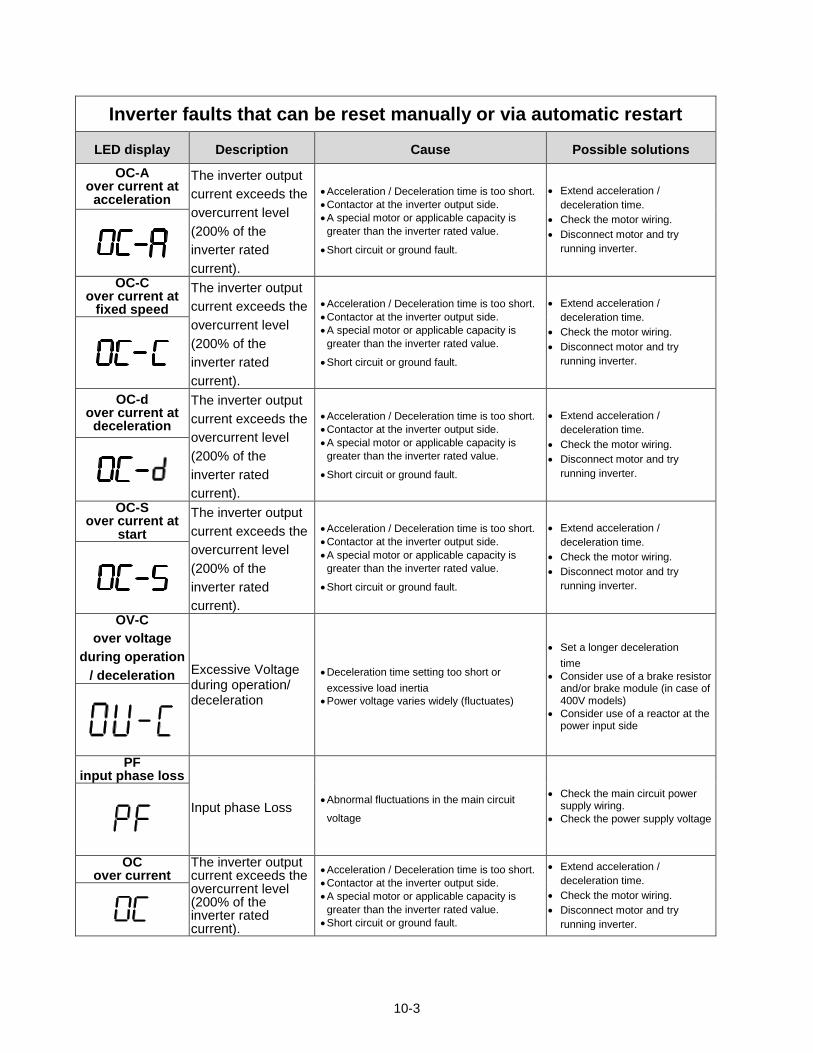
10-3
Inverter faults that can be reset manually or via automatic restart
LED display Description Cause Possible solutions
OC-A over current at
acceleration
The inverter output
current exceeds the
overcurrent level
(200% of the
inverter rated
current).
Acceleration / Deceleration time is too short.
Contactor at the inverter output side.
A special motor or applicable capacity is
greater than the inverter rated value.
Short circuit or ground fault.
Extend acceleration /
deceleration time.
Check the motor wiring.
Disconnect motor and try
running inverter.
OC-C over current at
fixed speed
The inverter output
current exceeds the
overcurrent level
(200% of the
inverter rated
current).
Acceleration / Deceleration time is too short.
Contactor at the inverter output side.
A special motor or applicable capacity is
greater than the inverter rated value.
Short circuit or ground fault.
Extend acceleration /
deceleration time.
Check the motor wiring.
Disconnect motor and try
running inverter.
OC-d over current at deceleration
The inverter output
current exceeds the
overcurrent level
(200% of the
inverter rated
current).
Acceleration / Deceleration time is too short.
Contactor at the inverter output side.
A special motor or applicable capacity is
greater than the inverter rated value.
Short circuit or ground fault.
Extend acceleration /
deceleration time.
Check the motor wiring.
Disconnect motor and try
running inverter.
OC-S over current at
start
The inverter output
current exceeds the
overcurrent level
(200% of the
inverter rated
current).
Acceleration / Deceleration time is too short.
Contactor at the inverter output side.
A special motor or applicable capacity is
greater than the inverter rated value.
Short circuit or ground fault.
Extend acceleration /
deceleration time.
Check the motor wiring.
Disconnect motor and try
running inverter.
OV-C
over voltage
during operation
/ deceleration Excessive Voltage during operation/ deceleration
Deceleration time setting too short or
excessive load inertia
Power voltage varies widely (fluctuates)
Set a longer deceleration
time
Consider use of a brake resistor and/or brake module (in case of 400V models)
Consider use of a reactor at the power input side
PF input phase loss
Input phase Loss Abnormal fluctuations in the main circuit
voltage
Check the main circuit power supply wiring.
Check the power supply voltage
OC over current
The inverter output current exceeds the overcurrent level (200% of the inverter rated current).
Acceleration / Deceleration time is too short.
Contactor at the inverter output side.
A special motor or applicable capacity is
greater than the inverter rated value.
Short circuit or ground fault.
Extend acceleration /
deceleration time.
Check the motor wiring.
Disconnect motor and try
running inverter.
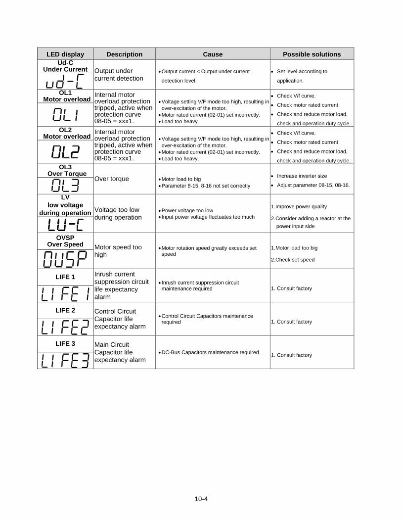
10-4
LED display Description Cause Possible solutions
Ud-C Under Current Output under
current detection Output current < Output under current
detection level.
Set level according to
application.
OL1
Motor overload Internal motor overload protection tripped, active when protection curve 08-05 = xxx1.
Voltage setting V/F mode too high, resulting in
over-excitation of the motor.
Motor rated current (02-01) set incorrectly.
Load too heavy.
Check V/f curve.
Check motor rated current
Check and reduce motor load,
check and operation duty cycle.
OL2 Motor overload
Internal motor overload protection tripped, active when protection curve 08-05 = xxx1.
Voltage setting V/F mode too high, resulting in
over-excitation of the motor.
Motor rated current (02-01) set incorrectly.
Load too heavy.
Check V/f curve.
Check motor rated current
Check and reduce motor load,
check and operation duty cycle.
OL3 Over Torque
Over torque
Motor load to big
Parameter 8-15, 8-16 not set correctly
Increase inverter size
Adjust parameter 08-15, 08-16.
LV
low voltage
during operation Voltage too low during operation
Power voltage too low
Input power voltage fluctuates too much
1.Improve power quality
2.Consider adding a reactor at the
power input side
OVSP Over Speed Motor speed too
high Motor rotation speed greatly exceeds set speed
1.Motor load too big
2.Check set speed
LIFE 1 Inrush current suppression circuit life expectancy alarm
Inrush current suppression circuit maintenance required 1. Consult factory
LIFE 2 Control Circuit Capacitor life expectancy alarm
Control Circuit Capacitors maintenance required 1. Consult factory
LIFE 3 Main Circuit Capacitor life expectancy alarm
DC-Bus Capacitors maintenance required 1. Consult factory
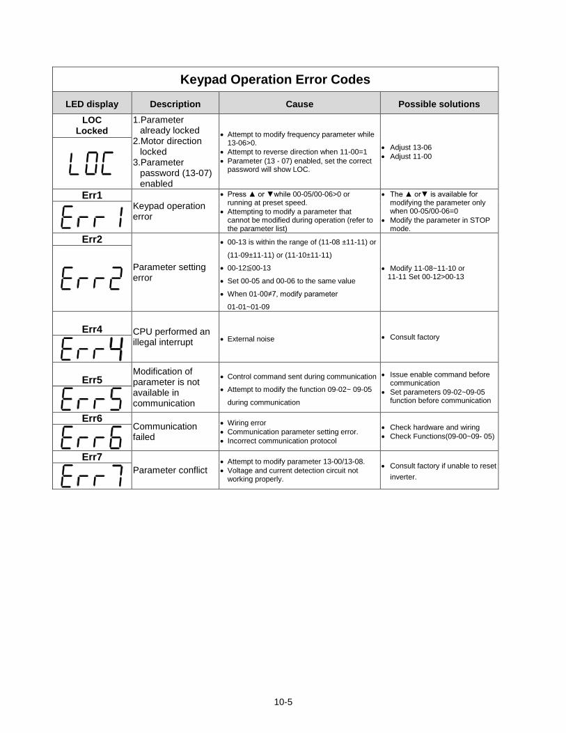
10-5
Keypad Operation Error Codes
LED display Description Cause Possible solutions
LOC Locked
1.Parameter already locked
2.Motor direction locked
3.Parameter password (13-07) enabled
Attempt to modify frequency parameter while 13-06>0.
Attempt to reverse direction when 11-00=1
Parameter (13 - 07) enabled, set the correct password will show LOC.
Adjust 13-06
Adjust 11-00
Err1 Keypad operation error
Press or while 00-05/00-06>0 or running at preset speed.
Attempting to modify a parameter that cannot be modified during operation (refer to the parameter list)
The or is available for modifying the parameter only when 00-05/00-06=0
Modify the parameter in STOP mode.
Err2
Parameter setting error
00-13 is within the range of (11-08 ±11-11) or
(11-09±11-11) or (11-10±11-11)
00-12≦00-13
Set 00-05 and 00-06 to the same value
When 01-00≠7, modify parameter
01-01~01-09
Modify 11-08~11-10 or 11-11 Set 00-12>00-13
Err4 CPU performed an
illegal interrupt External noise Consult factory
Err5 Modification of parameter is not available in communication
Control command sent during communication
Attempt to modify the function 09-02~ 09-05
during communication
Issue enable command before communication
Set parameters 09-02~09-05 function before communication
Err6
Communication failed
Wiring error
Communication parameter setting error.
Incorrect communication protocol
Check hardware and wiring
Check Functions(09-00~09- 05)
Err7
Parameter conflict Attempt to modify parameter 13-00/13-08.
Voltage and current detection circuit not working properly.
Consult factory if unable to reset
inverter.
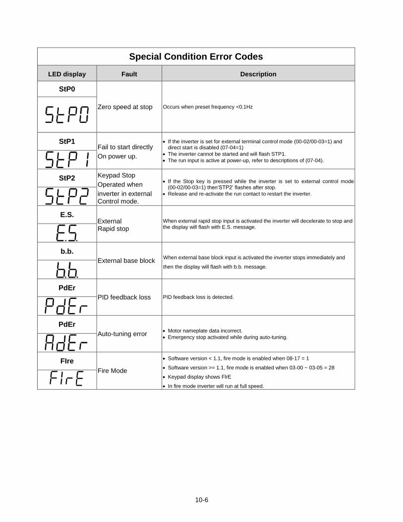
10-6
Special Condition Error Codes
LED display Fault Description
StP0
Zero speed at stop Occurs when preset frequency <0.1Hz
StP1 Fail to start directly
On power up.
If the inverter is set for external terminal control mode (00-02/00-03=1) and direct start is disabled (07-04=1)
The inverter cannot be started and will flash STP1.
The run input is active at power-up, refer to descriptions of (07-04).
StP2 Keypad Stop
Operated when
inverter in external Control mode.
If the Stop key is pressed while the inverter is set to external control mode (00-02/00-03=1) then‘STP2’ flashes after stop.
Release and re-activate the run contact to restart the inverter.
E.S. External Rapid stop
When external rapid stop input is activated the inverter will decelerate to stop and the display will flash with E.S. message.
b.b.
External base block When external base block input is activated the inverter stops immediately and
then the display will flash with b.b. message.
PdEr
PID feedback loss PID feedback loss is detected.
PdEr
Auto-tuning error Motor nameplate data incorrect.
Emergency stop activated while during auto-tuning.
FIre
Fire Mode
Software version < 1.1, fire mode is enabled when 08-17 = 1
Software version >= 1.1, fire mode is enabled when 03-00 ~ 03-05 = 28
Keypad display shows FlrE
In fire mode inverter will run at full speed.
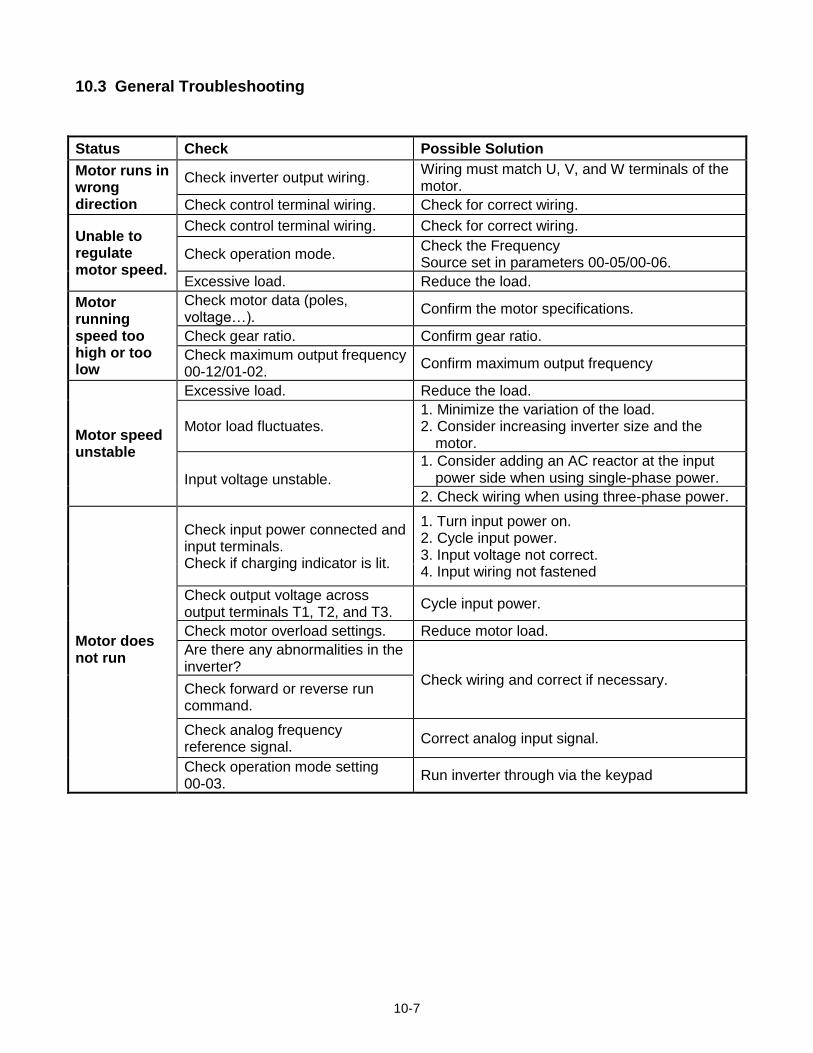
10-7
10.3 General Troubleshooting
Status Check Possible Solution
Motor runs in wrong direction
Check inverter output wiring. Wiring must match U, V, and W terminals of the motor.
Check control terminal wiring. Check for correct wiring.
Unable to regulate motor speed.
Check control terminal wiring. Check for correct wiring.
Check operation mode. Check the Frequency Source set in parameters 00-05/00-06.
Excessive load. Reduce the load.
Motor running speed too high or too low
Check motor data (poles, voltage…).
Confirm the motor specifications.
Check gear ratio. Confirm gear ratio.
Check maximum output frequency 00-12/01-02.
Confirm maximum output frequency
Motor speed unstable
Excessive load. Reduce the load.
Motor load fluctuates. 1. Minimize the variation of the load. 2. Consider increasing inverter size and the
motor.
Input voltage unstable.
1. Consider adding an AC reactor at the input power side when using single-phase power.
2. Check wiring when using three-phase power.
Motor does not run
Check input power connected and input terminals. Check if charging indicator is lit.
1. Turn input power on. 2. Cycle input power. 3. Input voltage not correct. 4. Input wiring not fastened
Check output voltage across output terminals T1, T2, and T3.
Cycle input power.
Check motor overload settings. Reduce motor load.
Are there any abnormalities in the inverter?
Check wiring and correct if necessary. Check forward or reverse run command.
Check analog frequency reference signal.
Correct analog input signal.
Check operation mode setting 00-03.
Run inverter through via the keypad
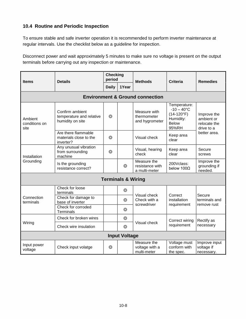
10-8
10.4 Routine and Periodic Inspection
To ensure stable and safe inverter operation it is recommended to perform inverter maintenance at
regular intervals. Use the checklist below as a guideline for inspection.
Disconnect power and wait approximately 5 minutes to make sure no voltage is present on the output
terminals before carrying out any inspection or maintenance.
Items Details
Checking period
Methods Criteria Remedies
Daily 1Year
Environment & Ground connection
Ambient conditions on site
Confirm ambient temperature and relative humidity on site
Measure with thermometer and hygrometer
Temperature: -10 – 40°C (14-120°F) Humidity: Below 95%RH
Improve the ambient or relocate the drive to a better area. Are there flammable
materials close to the inverter?
Visual check Keep area clear
Installation Grounding
Any unusual vibration from surrounding machine
Visual, hearing check
Keep area clear
Secure screws
Is the grounding resistance correct?
Measure the resistance with a multi-meter
200Vclass: below 100Ω
Improve the grounding if needed.
Terminals & Wiring
Connection terminals
Check for loose terminals
Visual check Check with a screwdriver
Correct installation requirement
Secure terminals and remove rust
Check for damage to base of inverter
Check for corroded Terminals
Wiring Check for broken wires
Visual check Correct wiring requirement
Rectify as necessary Check wire insulation
Input Voltage
Input power voltage
Check input volatge Measure the voltage with a multi-meter
Voltage must conform with the spec.
Improve input voltage if necessary.
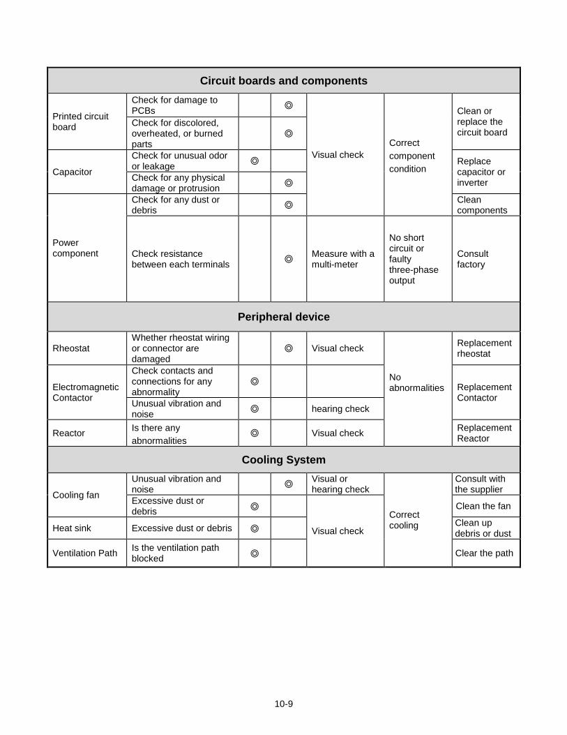
10-9
Circuit boards and components
Printed circuit board
Check for damage to PCBs
Visual check
Correct
component
condition
Clean or replace the circuit board
Check for discolored, overheated, or burned parts
Capacitor
Check for unusual odor or leakage
Replace capacitor or inverter
Check for any physical damage or protrusion
Power component
Check for any dust or debris
Clean components
Check resistance between each terminals
Measure with a multi-meter
No short circuit or faulty three-phase output
Consult factory
Peripheral device
Rheostat Whether rheostat wiring or connector are damaged
Visual check
No abnormalities
Replacement rheostat
Electromagnetic Contactor
Check contacts and connections for any abnormality
Replacement Contactor
Unusual vibration and noise
hearing check
Reactor Is there any
abnormalities Visual check
Replacement Reactor
Cooling System
Cooling fan
Unusual vibration and noise
Visual or hearing check
Correct cooling
Consult with the supplier
Excessive dust or debris
Visual check
Clean the fan
Heat sink Excessive dust or debris Clean up debris or dust
Ventilation Path Is the ventilation path blocked
Clear the path
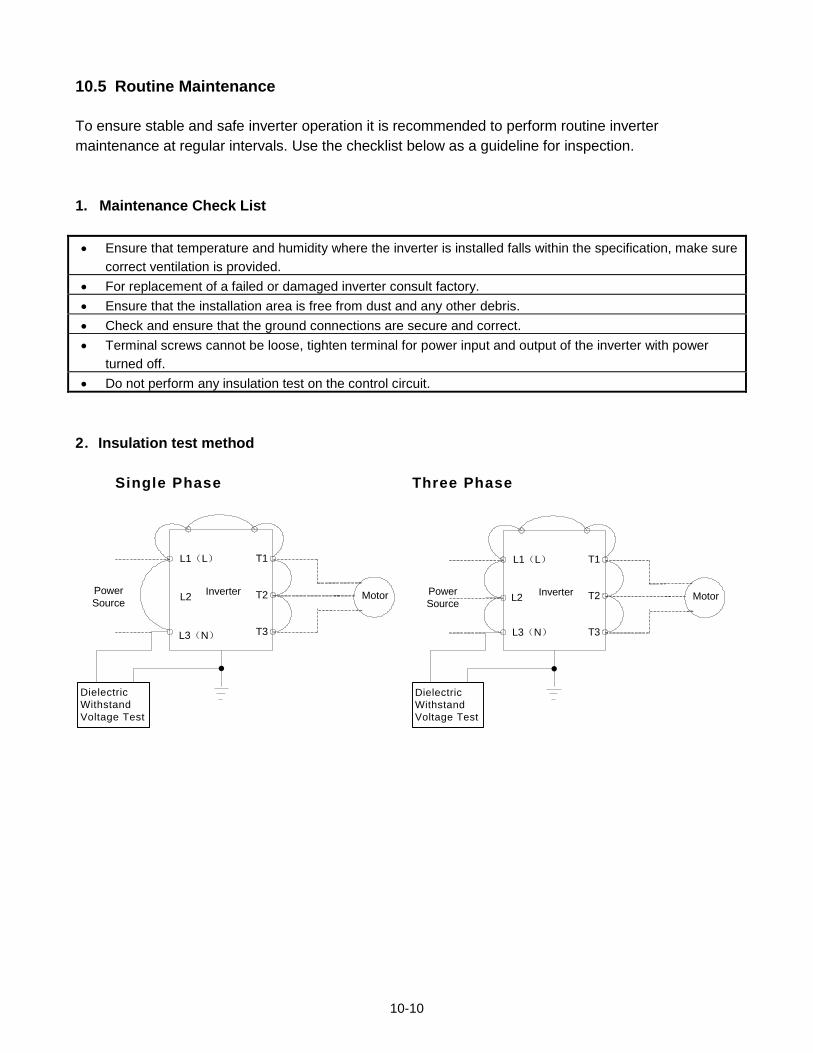
10-10
10.5 Routine Maintenance
To ensure stable and safe inverter operation it is recommended to perform routine inverter
maintenance at regular intervals. Use the checklist below as a guideline for inspection.
1. Maintenance Check List
Ensure that temperature and humidity where the inverter is installed falls within the specification, make sure
correct ventilation is provided.
For replacement of a failed or damaged inverter consult factory.
Ensure that the installation area is free from dust and any other debris.
Check and ensure that the ground connections are secure and correct.
Terminal screws cannot be loose, tighten terminal for power input and output of the inverter with power
turned off.
Do not perform any insulation test on the control circuit.
2.Insulation test method
Single Phase Three Phase
Inverter
L1(L)
L3(N)
T1
T2
T3
Dielectric
Withstand
Voltage Test
Power
SourceMotorL2
Inverter
L1(L)
L3(N)
T1
T2
T3
Dielectric
Withstand
Voltage Test
Power
SourceMotorL2
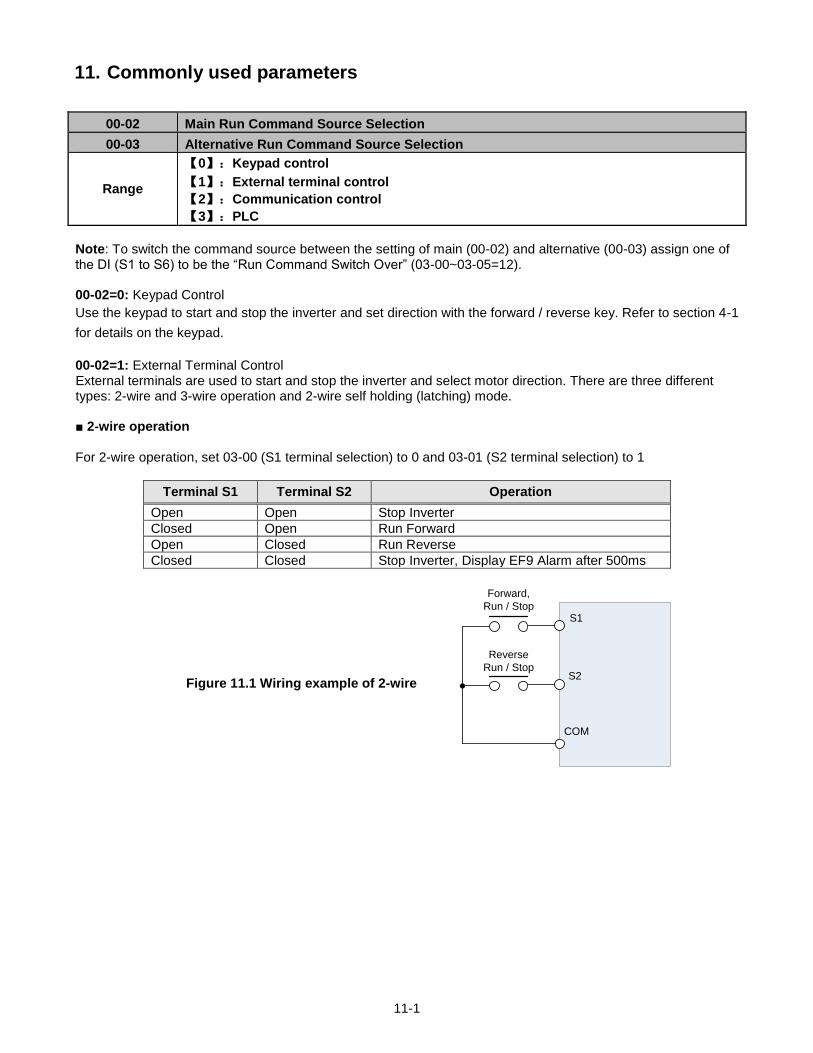
11-1
11. Commonly used parameters
00-02 Main Run Command Source Selection
00-03 Alternative Run Command Source Selection
Range
【0】:Keypad control
【1】:External terminal control
【2】:Communication control
【3】:PLC
Note: To switch the command source between the setting of main (00-02) and alternative (00-03) assign one of the DI (S1 to S6) to be the “Run Command Switch Over” (03-00~03-05=12). 00-02=0: Keypad Control
Use the keypad to start and stop the inverter and set direction with the forward / reverse key. Refer to section 4-1
for details on the keypad.
00-02=1: External Terminal Control External terminals are used to start and stop the inverter and select motor direction. There are three different types: 2-wire and 3-wire operation and 2-wire self holding (latching) mode. 2-wire operation For 2-wire operation, set 03-00 (S1 terminal selection) to 0 and 03-01 (S2 terminal selection) to 1
Terminal S1 Terminal S2 Operation
Open Open Stop Inverter
Closed Open Run Forward
Open Closed Run Reverse
Closed Closed Stop Inverter, Display EF9 Alarm after 500ms
Figure 11.1 Wiring example of 2-wire
S1
S2
COM
Forward,
Run / Stop
Reverse
Run / Stop
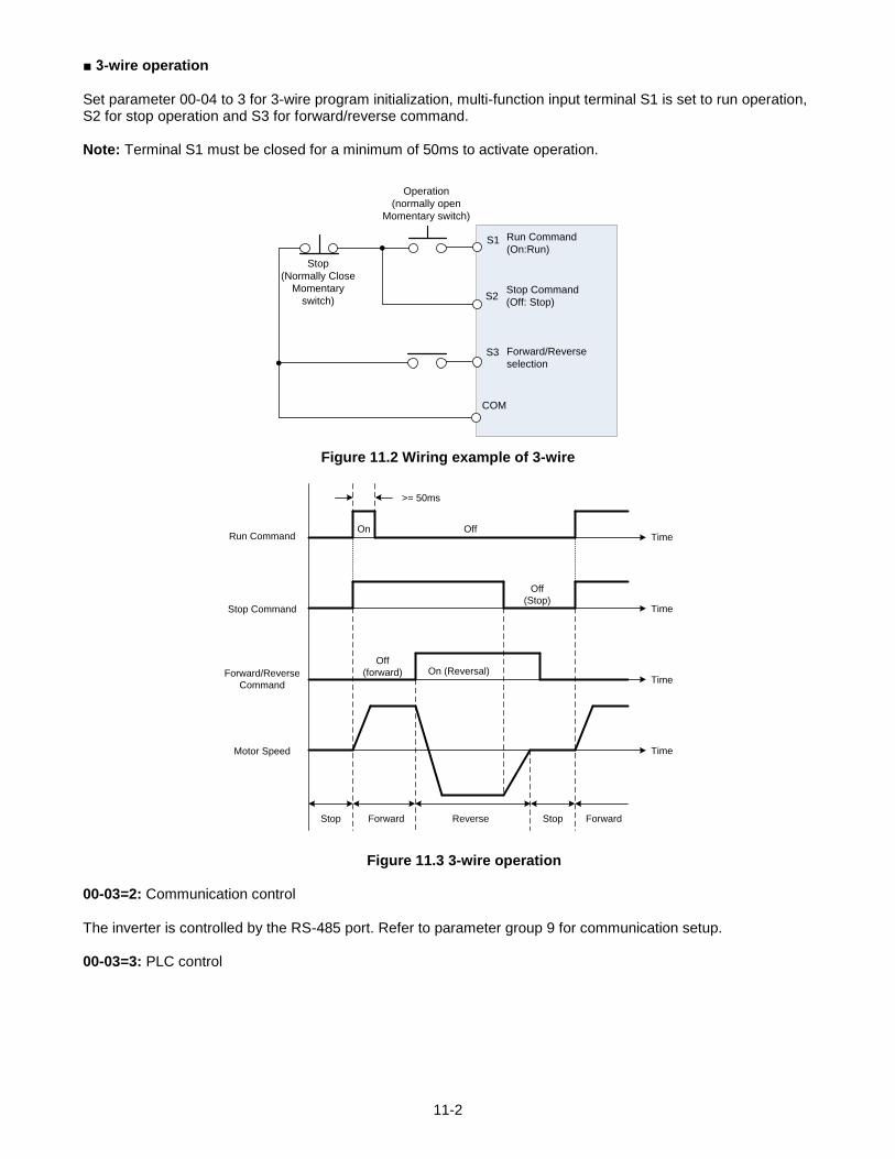
11-2
3-wire operation Set parameter 00-04 to 3 for 3-wire program initialization, multi-function input terminal S1 is set to run operation, S2 for stop operation and S3 for forward/reverse command. Note: Terminal S1 must be closed for a minimum of 50ms to activate operation.
S1
S2
S3 Forward/Reverse
selection
COM
Operation
(normally open
Momentary switch)
Stop
(Normally Close
Momentary
switch)Stop Command
(Off: Stop)
Run Command
(On:Run)
Figure 11.2 Wiring example of 3-wire
Time
Time
Time
Time
Run Command
Stop Command
Forward/Reverse
Command
Motor Speed
Off
Off
(Stop)
Off
(forward) On (Reversal)
Stop Forward Reverse Stop Forward
On
>= 50ms
Figure 11.3 3-wire operation 00-03=2: Communication control The inverter is controlled by the RS-485 port. Refer to parameter group 9 for communication setup. 00-03=3: PLC control
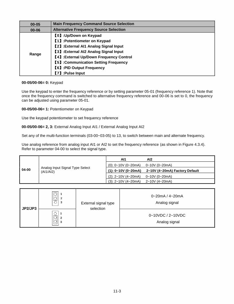
11-3
00-05 Main Frequency Command Source Selection
00-06 Alternative Frequency Source Selection
Range
【0】:Up/Down on Keypad
【1】:Potentiometer on Keypad
【2】:External AI1 Analog Signal Input
【3】:External AI2 Analog Signal Input
【4】:External Up/Down Frequency Control
【5】:Communication Setting Frequency
【6】:PID Output Frequency
【7】:Pulse Input
00-05/00-06= 0: Keypad Use the keypad to enter the frequency reference or by setting parameter 05-01 (frequency reference 1). Note that once the frequency command is switched to alternative frequency reference and 00-06 is set to 0, the frequency can be adjusted using parameter 05-01. 00-05/00-06= 1: Potentiometer on Keypad Use the keypad potentiometer to set frequency reference 00-05/00-06= 2, 3: External Analog Input AI1 / External Analog Input AI2 Set any of the multi-function terminals (03-00~03-05) to 13, to switch between main and alternate frequency. Use analog reference from analog input AI1 or AI2 to set the frequency reference (as shown in Figure 4.3.4). Refer to parameter 04-00 to select the signal type.
04-00 Analog Input Signal Type Select (AI1/AI2)
AI1 AI2
(0): 0~10V (0~20mA) 0~10V (0~20mA)
(1): 0~10V (0~20mA) 2~10V (4~20mA) Factory Default
(2): 2~10V (4~20mA) 0~10V (0~20mA)
(3): 2~10V (4~20mA) 2~10V (4~20mA)
JP2/JP3 External signal type
selection
0~20mA / 4~20mA
Analog signal
0~10VDC / 2~10VDC
Analog signal
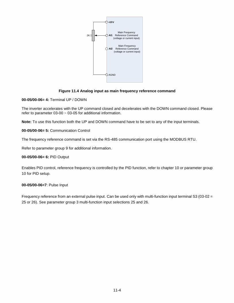
11-4
+ V
AGND
2KΩ AI1
AI2
Main Frequency
Reference Command
(voltage or current input)
10
Main Frequency
Reference Command
(voltage or current input)
Figure 11.4 Analog input as main frequency reference command
00-05/00-06= 4: Terminal UP / DOWN The inverter accelerates with the UP command closed and decelerates with the DOWN command closed. Please refer to parameter 03-00 ~ 03-05 for additional information. Note: To use this function both the UP and DOWN command have to be set to any of the input terminals.
00-05/00-06= 5: Communication Control The frequency reference command is set via the RS-485 communication port using the MODBUS RTU. Refer to parameter group 9 for additional information. 00-05/00-06= 6: PID Output
Enables PID control, reference frequency is controlled by the PID function, refer to chapter 10 or parameter group
10 for PID setup.
00-05/00-06=7: Pulse Input
Frequency reference from an external pulse input. Can be used only with multi-function input terminal S3 (03-02 =
25 or 26). See parameter group 3 multi-function input selections 25 and 26.
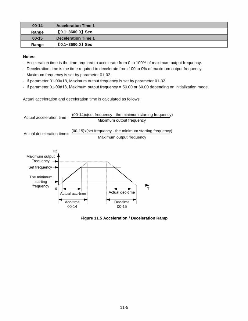
11-5
00-14 Acceleration Time 1
Range 【0.1~3600.0】Sec
00-15 Deceleration Time 1
Range 【0.1~3600.0】Sec
Notes:
- Acceleration time is the time required to accelerate from 0 to 100% of maximum output frequency.
- Deceleration time is the time required to decelerate from 100 to 0% of maximum output frequency.
- Maximum frequency is set by parameter 01-02.
- If parameter 01-00=18, Maximum output frequency is set by parameter 01-02.
- If parameter 01-00≠18, Maximum output frequency = 50.00 or 60.00 depending on initialization mode.
Actual acceleration and deceleration time is calculated as follows:
(00-15)x(set frequency - the minimum starting frequency)
Actual acceleration time=(00-14)x(set frequency - the minimum starting frequency)
Maximum output frequency
Actual deceleration time=Maximum output frequency
Maximum output
Frequency
Set frequency
Acc-time
00-14
Dec-time
00-15
Actual acc-time Actual dec-time
Hz
T0
The minimum
starting
frequency
Figure 11.5 Acceleration / Deceleration Ramp
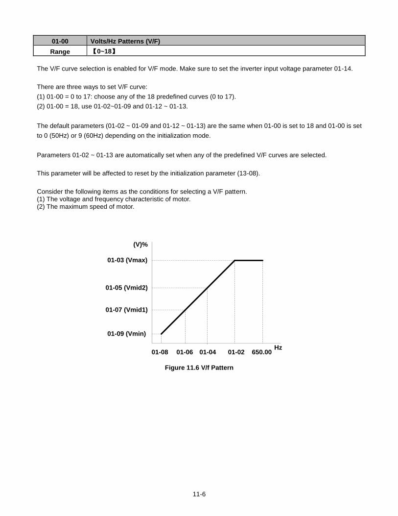
11-6
01-00 Volts/Hz Patterns (V/F)
Range 【0~18】
The V/F curve selection is enabled for V/F mode. Make sure to set the inverter input voltage parameter 01-14.
There are three ways to set V/F curve:
(1) 01-00 = 0 to 17: choose any of the 18 predefined curves (0 to 17).
(2) 01-00 = 18, use 01-02~01-09 and 01-12 ~ 01-13.
The default parameters (01-02 ~ 01-09 and 01-12 ~ 01-13) are the same when 01-00 is set to 18 and 01-00 is set
to 0 (50Hz) or 9 (60Hz) depending on the initialization mode.
Parameters 01-02 ~ 01-13 are automatically set when any of the predefined V/F curves are selected.
This parameter will be affected to reset by the initialization parameter (13-08).
Consider the following items as the conditions for selecting a V/F pattern. (1) The voltage and frequency characteristic of motor. (2) The maximum speed of motor.
01-03 (Vmax)
01-05 (Vmid2)
01-07 (Vmid1)
01-09 (Vmin)
01-08 01-06 01-04 01-02
(V)%
Hz650.00
Figure 11.6 V/f Pattern
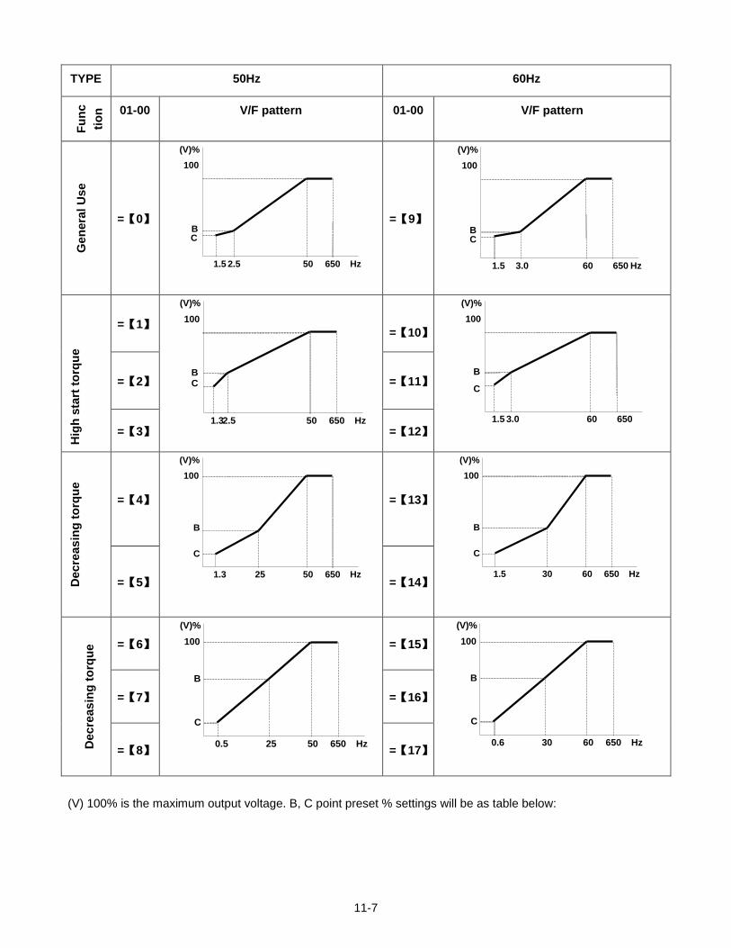
11-7
TYPE 50Hz 60Hz F
un
c
tio
n
01-00 V/F pattern
01-00 V/F pattern
Gen
era
l U
se
=【0】
100
BC
1.5 2.5 50
(V)%
Hz650
=【9】
100
BC
1.5 3.0 60
(V)%
Hz650
Hig
h s
tart
to
rqu
e
=【1】 100
BC
1.32.5 50
(V)%
Hz650
=【10】
100
B
C
1.5 3.0 60
(V)%
650
=【2】 =【11】
=【3】 =【12】
Decre
as
ing
to
rqu
e
=【4】
100
B
C
1.3 25 50
(V)%
Hz650
=【13】
100
B
C
1.5 30 60
(V)%
Hz650
=【5】 =【14】
Decre
as
ing
to
rqu
e
=【6】 100
B
C
0.5 25 50
(V)%
Hz650
=【15】 100
B
C
0.6 30 60
(V)%
Hz650
=【7】 =【16】
=【8】 =【17】
(V) 100% is the maximum output voltage. B, C point preset % settings will be as table below:
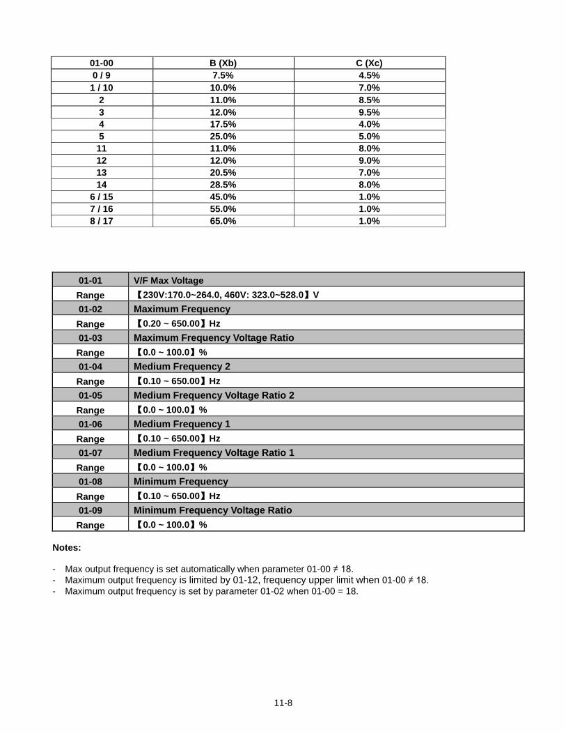
11-8
01-01 V/F Max Voltage
Range 【230V:170.0~264.0, 460V: 323.0~528.0】V
01-02 Maximum Frequency
Range 【0.20 ~ 650.00】Hz
01-03 Maximum Frequency Voltage Ratio
Range 【0.0 ~ 100.0】%
01-04 Medium Frequency 2
Range 【0.10 ~ 650.00】Hz
01-05 Medium Frequency Voltage Ratio 2
Range 【0.0 ~ 100.0】%
01-06 Medium Frequency 1
Range 【0.10 ~ 650.00】Hz
01-07 Medium Frequency Voltage Ratio 1
Range 【0.0 ~ 100.0】%
01-08 Minimum Frequency
Range 【0.10 ~ 650.00】Hz
01-09 Minimum Frequency Voltage Ratio
Range 【0.0 ~ 100.0】%
Notes:
- Max output frequency is set automatically when parameter 01-00 ≠ 18.
- Maximum output frequency is limited by 01-12, frequency upper limit when 01-00 ≠ 18.
- Maximum output frequency is set by parameter 01-02 when 01-00 = 18.
01-00 B (Xb) C (Xc)
0 / 9 7.5% 4.5%
1 / 10 10.0% 7.0%
2 11.0% 8.5%
3 12.0% 9.5%
4 17.5% 4.0%
5 25.0% 5.0%
11 11.0% 8.0%
12 12.0% 9.0%
13 20.5% 7.0%
14 28.5% 8.0%
6 / 15 45.0% 1.0%
7 / 16 55.0% 1.0%
8 / 17 65.0% 1.0%
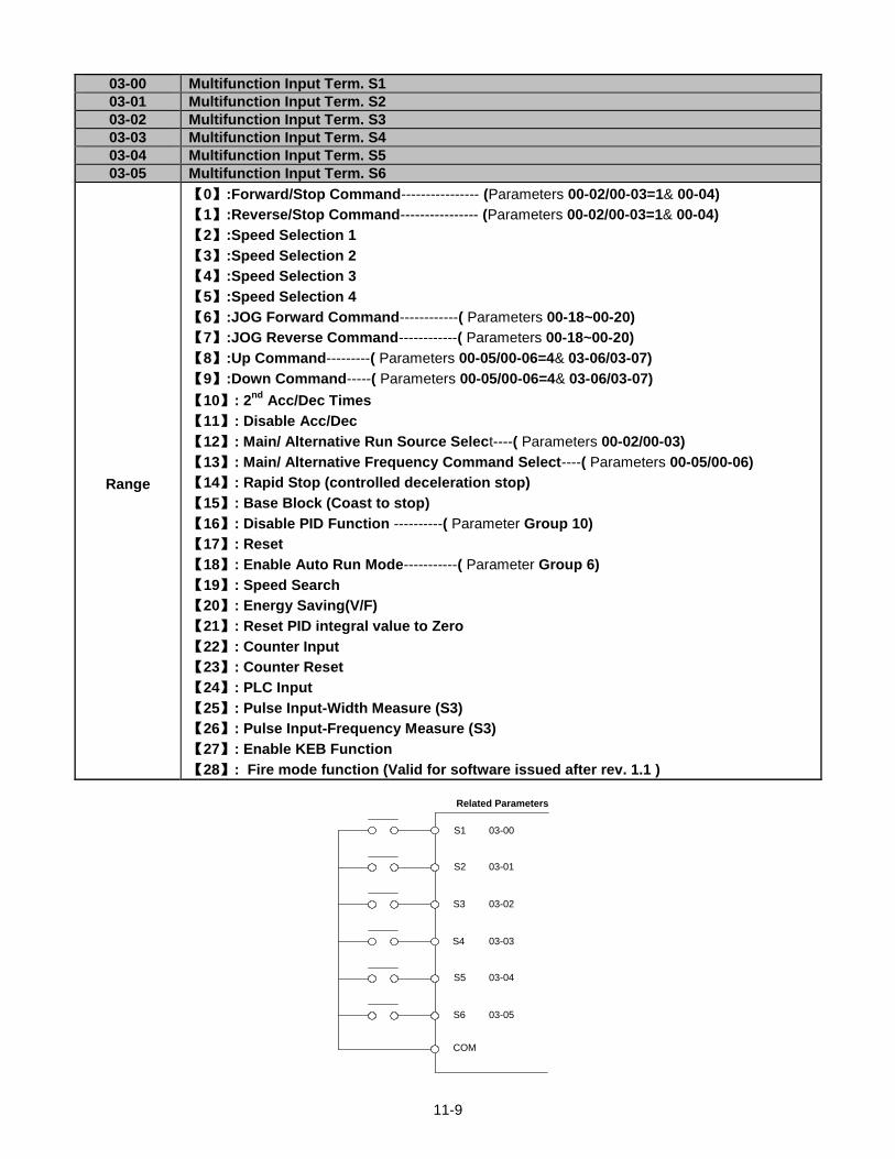
11-9
03-00 Multifunction Input Term. S1
03-01 Multifunction Input Term. S2
03-02 Multifunction Input Term. S3
03-03 Multifunction Input Term. S4
03-04 Multifunction Input Term. S5
03-05 Multifunction Input Term. S6
Range
【0】:Forward/Stop Command---------------- (Parameters 00-02/00-03=1& 00-04)
【1】:Reverse/Stop Command---------------- (Parameters 00-02/00-03=1& 00-04)
【2】:Speed Selection 1
【3】:Speed Selection 2
【4】:Speed Selection 3
【5】:Speed Selection 4
【6】:JOG Forward Command------------( Parameters 00-18~00-20)
【7】:JOG Reverse Command------------( Parameters 00-18~00-20)
【8】:Up Command---------( Parameters 00-05/00-06=4& 03-06/03-07)
【9】:Down Command-----( Parameters 00-05/00-06=4& 03-06/03-07)
【10】: 2nd
Acc/Dec Times
【11】: Disable Acc/Dec
【12】: Main/ Alternative Run Source Select----( Parameters 00-02/00-03)
【13】: Main/ Alternative Frequency Command Select----( Parameters 00-05/00-06)
【14】: Rapid Stop (controlled deceleration stop)
【15】: Base Block (Coast to stop)
【16】: Disable PID Function ----------( Parameter Group 10)
【17】: Reset
【18】: Enable Auto Run Mode-----------( Parameter Group 6)
【19】: Speed Search
【20】: Energy Saving(V/F)
【21】: Reset PID integral value to Zero
【22】: Counter Input
【23】: Counter Reset
【24】: PLC Input
【25】: Pulse Input-Width Measure (S3)
【26】: Pulse Input-Frequency Measure (S3)
【27】: Enable KEB Function
【28】: Fire mode function (Valid for software issued after rev. 1.1 )
S1
S2
S3
S4
S5
S6
Related Parameters
03-00
COM
03-01
03-02
03-03
03-04
03-05
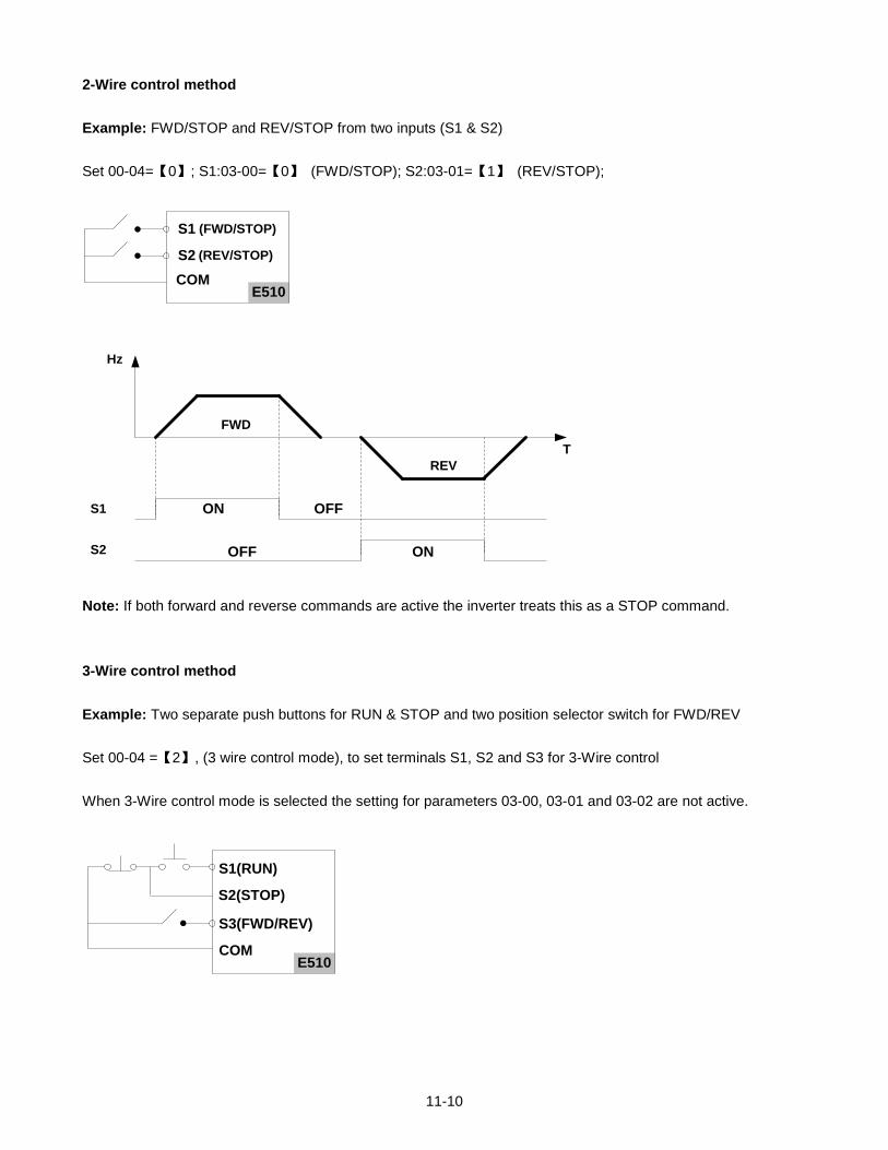
11-10
2-Wire control method
Example: FWD/STOP and REV/STOP from two inputs (S1 & S2)
Set 00-04=【0】; S1:03-00=【0】 (FWD/STOP); S2:03-01=【1】 (REV/STOP);
E510
S1
S2
COM
(FWD/STOP)
(REV/STOP)
S1 ON OFF
FWD
REV
ONOFFS2
Hz
T
Note: If both forward and reverse commands are active the inverter treats this as a STOP command.
3-Wire control method
Example: Two separate push buttons for RUN & STOP and two position selector switch for FWD/REV
Set 00-04 =【2】, (3 wire control mode), to set terminals S1, S2 and S3 for 3-Wire control
When 3-Wire control mode is selected the setting for parameters 03-00, 03-01 and 03-02 are not active.
E510
S1(RUN)
S2(STOP)
S3(FWD/REV)
COM
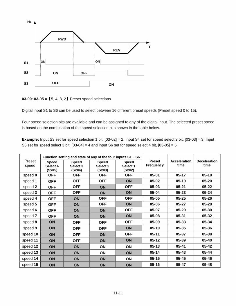
11-11
S1
OFF
FWD
REV
S2
S3
ON
ON ON
Hz
T
OFFON
03-00~03-05 =【5, 4, 3, 2】Preset speed selections
Digital input S1 to S6 can be used to select between 16 different preset speeds (Preset speed 0 to 15).
Four speed selection bits are available and can be assigned to any of the digital input. The selected preset speed
is based on the combination of the speed selection bits shown in the table below.
Example: Input S3 set for speed selection 1 bit, [03-02] = 2, Input S4 set for speed select 2 bit, [03-03] = 3, Input
S5 set for speed select 3 bit, [03-04] = 4 and input S6 set for speed select 4 bit, [03-05] = 5.
Preset speed
Function setting and state of any of the four inputs S1 ~ S6
Preset Frequency
Acceleration time
Deceleration time
Speed Select 4 (Sx=5)
Speed Select 3 (Sx=4)
Speed Select 2 (Sx=3)
Speed Select 1 (Sx=2)
speed 0 OFF OFF OFF OFF 05-01 05-17 05-18
speed 1 OFF OFF OFF ON 05-02 05-19 05-20
speed 2 OFF OFF ON OFF 05-03 05-21 05-22
speed 3 OFF OFF ON ON 05-04 05-23 05-24
speed 4 OFF ON OFF OFF 05-05 05-25 05-26
speed 5 OFF ON OFF ON 05-06 05-27 05-28
speed 6 OFF ON ON OFF 05-07 05-29 05-30
speed 7 OFF ON ON ON 05-08 05-31 05-32
speed 8 ON OFF OFF OFF 05-09 05-33 05-34
speed 9 ON OFF OFF ON 05-10 05-35 05-36
speed 10 ON OFF ON OFF 05-11 05-37 05-38
speed 11 ON OFF ON ON 05-12 05-39 05-40
speed 12 ON ON ON ON 05-13 05-41 05-42
speed 13 ON ON ON ON 05-14 05-43 05-44
speed 14 ON ON ON ON 05-15 05-45 05-46
speed 15 ON ON ON ON 05-16 05-47 05-48
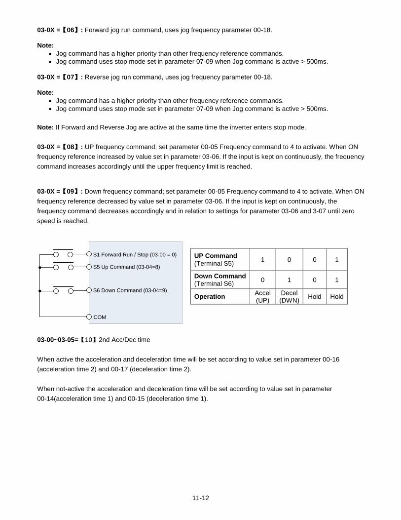
11-12
03-0X =【06】: Forward jog run command, uses jog frequency parameter 00-18.
Note:
Jog command has a higher priority than other frequency reference commands.
Jog command uses stop mode set in parameter 07-09 when Jog command is active > 500ms.
03-0X =【07】: Reverse jog run command, uses jog frequency parameter 00-18.
Note:
Jog command has a higher priority than other frequency reference commands.
Jog command uses stop mode set in parameter 07-09 when Jog command is active > 500ms.
Note: If Forward and Reverse Jog are active at the same time the inverter enters stop mode.
03-0X =【08】: UP frequency command; set parameter 00-05 Frequency command to 4 to activate. When ON
frequency reference increased by value set in parameter 03-06. If the input is kept on continuously, the frequency
command increases accordingly until the upper frequency limit is reached.
03-0X =【09】: Down frequency command; set parameter 00-05 Frequency command to 4 to activate. When ON
frequency reference decreased by value set in parameter 03-06. If the input is kept on continuously, the
frequency command decreases accordingly and in relation to settings for parameter 03-06 and 3-07 until zero
speed is reached.
UP Command (Terminal S5)
1 0 0 1
Down Command (Terminal S6)
0 1 0 1
Operation Accel (UP)
Decel (DWN)
Hold Hold
03-00~03-05=【10】2nd Acc/Dec time
When active the acceleration and deceleration time will be set according to value set in parameter 00-16
(acceleration time 2) and 00-17 (deceleration time 2).
When not-active the acceleration and deceleration time will be set according to value set in parameter
00-14(acceleration time 1) and 00-15 (deceleration time 1).
S1 Forward Run / Stop (03-00 = 0)
COM
S5 Up Command (03-04=8)
S6 Down Command (03-04=9)
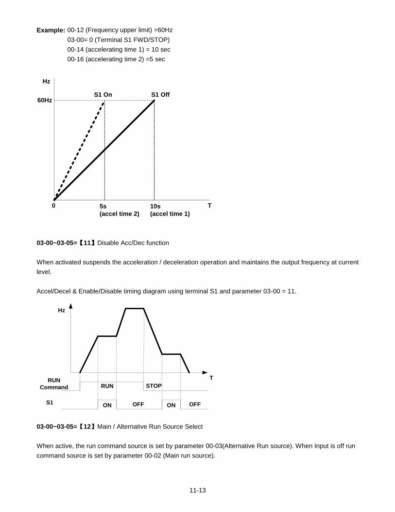
11-13
Example: 00-12 (Frequency upper limit) =60Hz
03-00= 0 (Terminal S1 FWD/STOP)
00-14 (accelerating time 1) = 10 sec
00-16 (accelerating time 2) =5 sec
60Hz
0 10s
(accel time 1)
Hz
T5s
(accel time 2)
S1 OffS1 On
03-00~03-05=【11】Disable Acc/Dec function
When activated suspends the acceleration / deceleration operation and maintains the output frequency at current
level.
Accel/Decel & Enable/Disable timing diagram using terminal S1 and parameter 03-00 = 11.
RUN
Command
S1
RUN STOP
ON OFF ON OFF
T
Hz
03-00~03-05=【12】Main / Alternative Run Source Select
When active, the run command source is set by parameter 00-03(Alternative Run source). When Input is off run
command source is set by parameter 00-02 (Main run source).
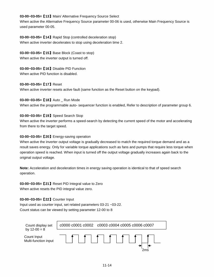
11-14
03-00~03-05=【13】Main/ Alternative Frequency Source Select
When active the Alternative Frequency Source parameter 00-06 is used, otherwise Main Frequency Source is
used parameter 00-05.
03-00~03-05=【14】Rapid Stop (controlled deceleration stop)
When active inverter decelerates to stop using deceleration time 2.
03-00~03-05=【15】Base Block (Coast to stop)
When active the inverter output is turned off.
03-00~03-05=【16】Disable PID Function
When active PID function is disabled.
03-00~03-05=【17】Reset
When active inverter resets active fault (same function as the Reset button on the keypad).
03-00~03-05=【18】Auto _ Run Mode
When active the programmable auto- sequencer function is enabled, Refer to description of parameter group 6.
03-00~03-05=【19】Speed Search Stop
When active the inverter performs a speed-search by detecting the current speed of the motor and accelerating
from there to the target speed.
03-00~03-05=【20】Energy-saving operation
When active the inverter output voltage is gradually decreased to match the required torque demand and as a
result saves energy. Only for variable torque applications such as fans and pumps that require less torque when
operation speed is reached. When input is turned off the output voltage gradually increases again back to the
original output voltage.
Note: Acceleration and deceleration times in energy saving operation is identical to that of speed search
operation.
03-00~03-05=【21】Reset PID Integral value to Zero
When active resets the PID integral value zero.
03-00~03-05=【22】Counter Input
Input used as counter input, set related parameters 03-21 ~03-22.
Count status can be viewed by setting parameter 12-00 to 8
Count Input Multi-function input
2ms
c0000 c0001 c0002 c0003 c0004 c0005 c0006 c0007 Count display set by 12-00 = 8
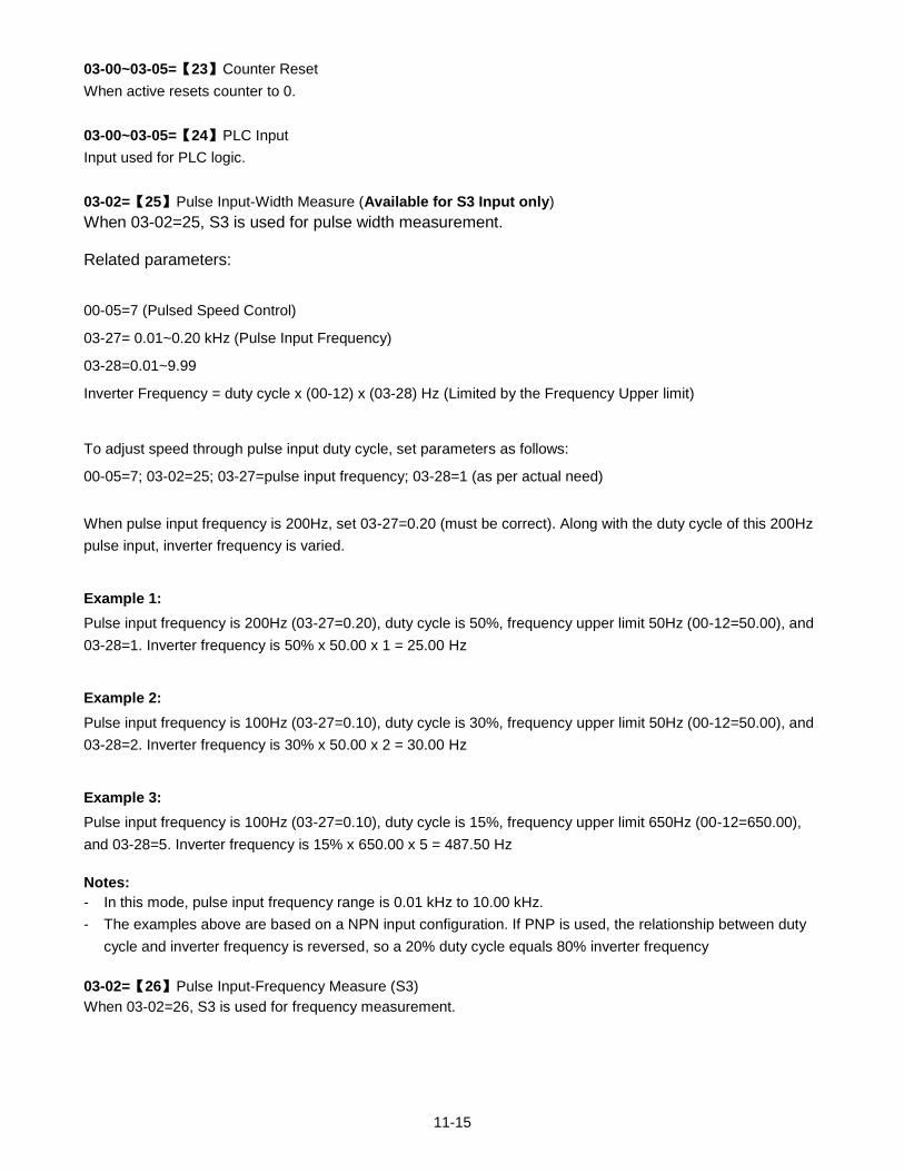
11-15
03-00~03-05=【23】Counter Reset
When active resets counter to 0.
03-00~03-05=【24】PLC Input
Input used for PLC logic.
03-02=【25】Pulse Input-Width Measure (Available for S3 Input only)
When 03-02=25, S3 is used for pulse width measurement. Related parameters:
00-05=7 (Pulsed Speed Control)
03-27= 0.01~0.20 kHz (Pulse Input Frequency)
03-28=0.01~9.99
Inverter Frequency = duty cycle x (00-12) x (03-28) Hz (Limited by the Frequency Upper limit)
To adjust speed through pulse input duty cycle, set parameters as follows:
00-05=7; 03-02=25; 03-27=pulse input frequency; 03-28=1 (as per actual need)
When pulse input frequency is 200Hz, set 03-27=0.20 (must be correct). Along with the duty cycle of this 200Hz
pulse input, inverter frequency is varied.
Example 1:
Pulse input frequency is 200Hz (03-27=0.20), duty cycle is 50%, frequency upper limit 50Hz (00-12=50.00), and
03-28=1. Inverter frequency is 50% x 50.00 x 1 = 25.00 Hz
Example 2:
Pulse input frequency is 100Hz (03-27=0.10), duty cycle is 30%, frequency upper limit 50Hz (00-12=50.00), and
03-28=2. Inverter frequency is 30% x 50.00 x 2 = 30.00 Hz
Example 3:
Pulse input frequency is 100Hz (03-27=0.10), duty cycle is 15%, frequency upper limit 650Hz (00-12=650.00),
and 03-28=5. Inverter frequency is 15% x 650.00 x 5 = 487.50 Hz
Notes:
- In this mode, pulse input frequency range is 0.01 kHz to 10.00 kHz.
- The examples above are based on a NPN input configuration. If PNP is used, the relationship between duty
cycle and inverter frequency is reversed, so a 20% duty cycle equals 80% inverter frequency
03-02=【26】Pulse Input-Frequency Measure (S3)
When 03-02=26, S3 is used for frequency measurement.
11-16
Related Parameters:
00-05=7 (Pulsed Speed Control)
03-02=26 (S3 is the pulse input- frequency measurement)
03-28=0.01~9.99
Inverter Frequency = f x (3-28) Hz, f: Pulse Input Frequency Hz (Limited by the Frequency Upper limit)
Set the following parameters to use pulse input for speed command:
00-05=7
03-02=26
03-28=1 (adjust if required)
03-27: Not used.
Example 1:
Pulse input frequency is 20Hz, frequency upper limit is 50Hz (00-12=50.00), and 03-28=1.
Inverter frequency is 20.00Hz
Example 2:
Pulse input frequency is 45Hz, frequency upper limit is 50Hz (00-12=50.00), and 03-28=1.
Inverter frequency is 45.00Hz
Example 3:
Pulse input frequency is 55Hz, frequency upper limit is 50Hz (00-12=50.00), and 03-28=1.
Inverter frequency is 50.00Hz
Example 4:
Pulse input frequency is 2000Hz, frequency upper limit is 650Hz (00-12=650.00), and 03-28=0.2.
Inverter frequency is 2000 x 0.2 = 400.00Hz
Notes:
- In this mode, pulse input frequency range is 0.01 kHz to 200Hz.
- Pulse input can only be selected for terminal S3
- PLC common is COM terminal on TM2
03-00~03-05=【27】 Enable KEB Function
When active enables KEB (Kinetic Energy Braking) during acceleration. Refer to the parameter description of
07-14.
11-17
03-00~03-05=【28】Fire Mode Function
When active inverter runs at maximum speed (parameter 00-12) ignoring any protective functions. Fire Mode
function can be used for applications following a fire where it is necessary for a motor to continue running without
interruption.
Example: Smoke exhaust fans used in buildings for fire evacuation.
Caution
The correct use of this function is the responsibility of the installer of the fire safety system. TWMC bares
no responsibility for direct or indirect damages or loss incurred as a result of using this function.
Warranty is void when inverter damage is caused by using Fire Mode.
Notes:
- To enable Fire Mode function set parameter 08-17 = 1
- The fire Mode function is activated by using one of the multifunction inputs S1 to S6 to a value of 28.
(Parameter 03-00~03-05).
- Fire mode can also be enabled by setting the functions of S1 to S6 via communication.
When Fire Mode is active:
- The keypad shows FIrE, and Fire Mode activation is recorded in the inverter fault log.
- The inverter will run up to the maximum frequency set in 00-12.
- The inverter will keep running unless main power is lost or the inverter breaks down.
- When Fire Mode is activated, all protection functions and alarms (e.g. ES, BB, OV, OC …), will be ignored.
- STOP key on the keypad is disabled during Fire Mode operation.
- To reset fire mode: turn power off, remove fire mode input signal, and power-up inverter.
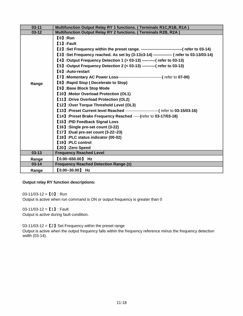
11-18
03-11 Multifunction Output Relay RY 1 functions. ( Terminals R1C,R1B, R1A )
03-12 Multifunction Output Relay RY 2 functions. ( Terminals R2B, R2A )
Range
【0】:Run
【1】:Fault
【2】:Set Frequency within the preset range. -------------------------------( refer to 03-14)
【3】:Set Frequency reached. As set by (3-13±3-14) -------------- ( refer to 03-13/03-14)
【4】:Output Frequency Detection 1 (> 03-13) ----------( refer to 03-13)
【5】:Output Frequency Detection 2 (< 03-13) ----------( refer to 03-13)
【6】:Auto-restart
【7】:Momentary AC Power Loss---------------------------------( refer to 07-00)
【8】:Rapid Stop ( Decelerate to Stop)
【9】:Base Block Stop Mode
【10】:Motor Overload Protection (OL1)
【11】:Drive Overload Protection (OL2)
【12】:Over Torque Threshold Level (OL3)
【13】:Preset Current level Reached -------------------------( refer to 03-15/03-16)
【14】:Preset Brake Frequency Reached -----(refer to 03-17/03-18)
【15】:PID Feedback Signal Loss
【16】:Single pre-set count (3-22)
【17】:Dual pre-set count (3-22~23)
【18】:PLC status indicator (00-02)
【19】:PLC control
【20】:Zero Speed
03-13 Frequency Reached Level
Range 【0.00~650.00】 Hz
03-14 Frequency Reached Detection Range (±)
Range 【0.00~30.00】 Hz
Output relay RY function descriptions:
03-11/03-12 =【0】: Run
Output is active when run command is ON or output frequency is greater than 0
03-11/03-12 =【1】: Fault
Output is active during fault condition.
03-11/03-12 =【2】Set Frequency within the preset range
Output is active when the output frequency falls within the frequency reference minus the frequency detection width (03-14).
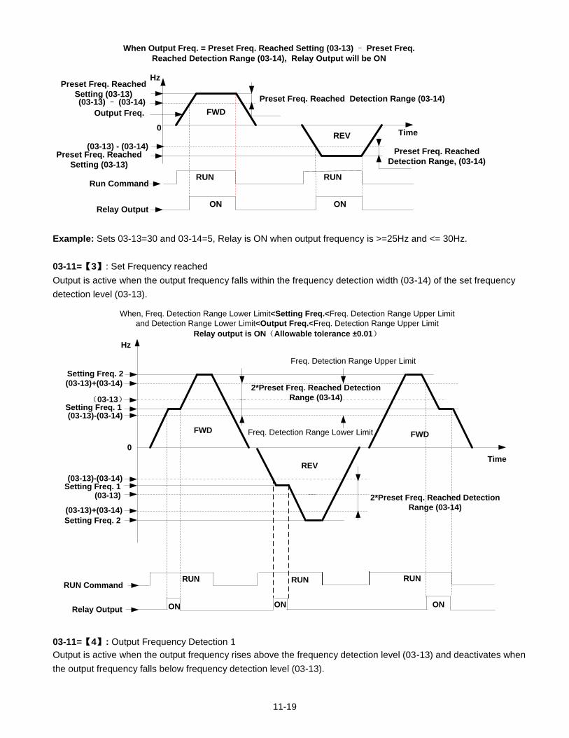
11-19
FWD
REV
Preset Freq. Reached
Setting (03-13)Preset Freq. Reached Detection Range (03-14)
When Output Freq. = Preset Freq. Reached Setting (03-13) – Preset Freq.
Reached Detection Range (03-14), Relay Output will be ON
Output Freq.
ON ONRelay Output
Hz
Time0
RUN RUNRun Command
(03-13) – (03-14)
Preset Freq. Reached
Detection Range, (03-14)
(03-13) - (03-14)Preset Freq. Reached
Setting (03-13)
Example: Sets 03-13=30 and 03-14=5, Relay is ON when output frequency is >=25Hz and <= 30Hz.
03-11=【3】: Set Frequency reached
Output is active when the output frequency falls within the frequency detection width (03-14) of the set frequency
detection level (03-13).
FWD
REV
Setting Freq. 2
Setting Freq. 1
Setting Freq. 1
Setting Freq. 2
2*Preset Freq. Reached Detection
Range (03-14)
Relay Output ON ON ON
RUN RUNRUNRUN Command
FWD
Hz
Time
0
When, Freq. Detection Range Lower Limit<Setting Freq.<Freq. Detection Range Upper Limit
and Detection Range Lower Limit<Output Freq.<Freq. Detection Range Upper Limit
Relay output is ON(Allowable tolerance ±0.01)
(03-13)
(03-13)+(03-14)
(03-13)-(03-14)
(03-13)
(03-13)-(03-14)
(03-13)+(03-14)
2*Preset Freq. Reached Detection
Range (03-14)
Freq. Detection Range Upper Limit
Freq. Detection Range Lower Limit
03-11=【4】: Output Frequency Detection 1
Output is active when the output frequency rises above the frequency detection level (03-13) and deactivates when
the output frequency falls below frequency detection level (03-13).
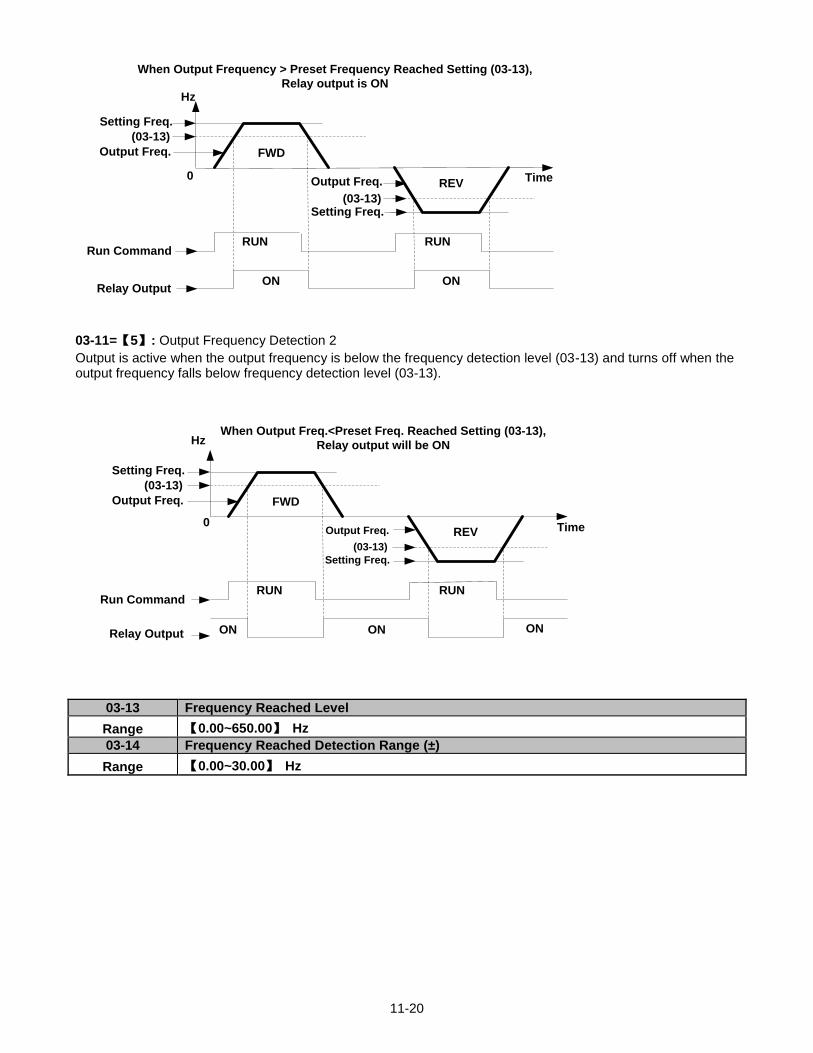
11-20
When Output Frequency > Preset Frequency Reached Setting (03-13),
Relay output is ON
FWD
REV
Setting Freq.
Setting Freq.
Output Freq.
Output Freq.
RUN RUN
ON ON
Run Command
Relay Output
(03-13)
(03-13)
Hz
Time0
03-11=【5】: Output Frequency Detection 2
Output is active when the output frequency is below the frequency detection level (03-13) and turns off when the output frequency falls below frequency detection level (03-13).
When Output Freq.<Preset Freq. Reached Setting (03-13),
Relay output will be ON
FWD
REV
Setting Freq.
Setting Freq.
Output Freq.
Output Freq.
RUN RUN
ON ON
Run Command
Relay Output
(03-13)
(03-13)
ON
Hz
Time0
03-13 Frequency Reached Level
Range 【0.00~650.00】 Hz
03-14 Frequency Reached Detection Range (±)
Range 【0.00~30.00】 Hz
T
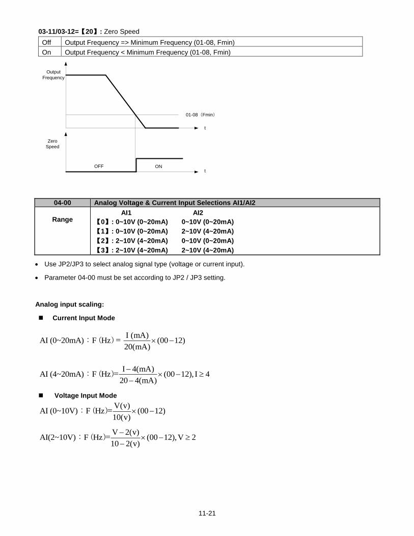
11-21
03-11/03-12=【20】: Zero Speed
Off Output Frequency => Minimum Frequency (01-08, Fmin)
On Output Frequency < Minimum Frequency (01-08, Fmin)
01-08(Fmin)
Output
Frequency
Zero
Speed
OFF ON
t
t
04-00 Analog Voltage & Current Input Selections AI1/AI2
Range
AI1 AI2
【0】: 0~10V (0~20mA) 0~10V (0~20mA)
【1】: 0~10V (0~20mA) 2~10V (4~20mA)
【2】: 2~10V (4~20mA) 0~10V (0~20mA)
【3】: 2~10V (4~20mA) 2~10V (4~20mA)
Use JP2/JP3 to select analog signal type (voltage or current input).
Parameter 04-00 must be set according to JP2 / JP3 setting.
Analog input scaling:
Current Input Mode
I (mA)AI (0~20mA) F Hz (00 12)
20(mA) : ( ) =
I 4(mA)AI (4~20mA) F Hz (00 12), I 4
20 4(mA)
: ( )=
Voltage Input Mode
V 2(v)AI(2~10V) F Hz (00 12),V 2
10 2(v)
: ( )=
V(v)AI (0~10V) F Hz (00 12)
10(v) : ( )=
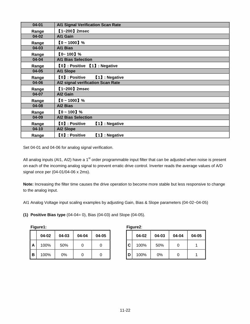
11-22
04-01 AI1 Signal Verification Scan Rate
Range 【1~200】2msec
04-02 AI1 Gain
Range 【0 ~ 1000】%
04-03 AI1 Bias
Range 【0~ 100】%
04-04 AI1 Bias Selection
Range 【0】: Positive 【1】: Negative
04-05 AI1 Slope
Range 【0】: Positive 【1】: Negative
04-06 AI2 signal verification Scan Rate
Range 【1~200】2msec
04-07 AI2 Gain
Range 【0 ~ 1000】%
04-08 AI2 Bias
Range 【0 ~ 100】%
04-09 AI2 Bias Selection
Range 【0】: Positive 【1】: Negative
04-10 AI2 Slope
Range 【0】: Positive 【1】: Negative
Set 04-01 and 04-06 for analog signal verification.
All analog inputs (AI1, AI2) have a 1st order programmable input filter that can be adjusted when noise is present
on each of the incoming analog signal to prevent erratic drive control. Inverter reads the average values of A/D
signal once per (04-01/04-06 x 2ms).
Note: Increasing the filter time causes the drive operation to become more stable but less responsive to change
to the analog input.
AI1 Analog Voltage input scaling examples by adjusting Gain, Bias & Slope parameters (04-02~04-05)
(1) Positive Bias type (04-04= 0), Bias (04-03) and Slope (04-05).
Figure1: Figure2:
04-02 04-03 04-04 04-05 04-02 04-03 04-04 04-05
A 100% 50% 0 0 C 100% 50% 0 1
B 100% 0% 0 0 D 100% 0% 0 1
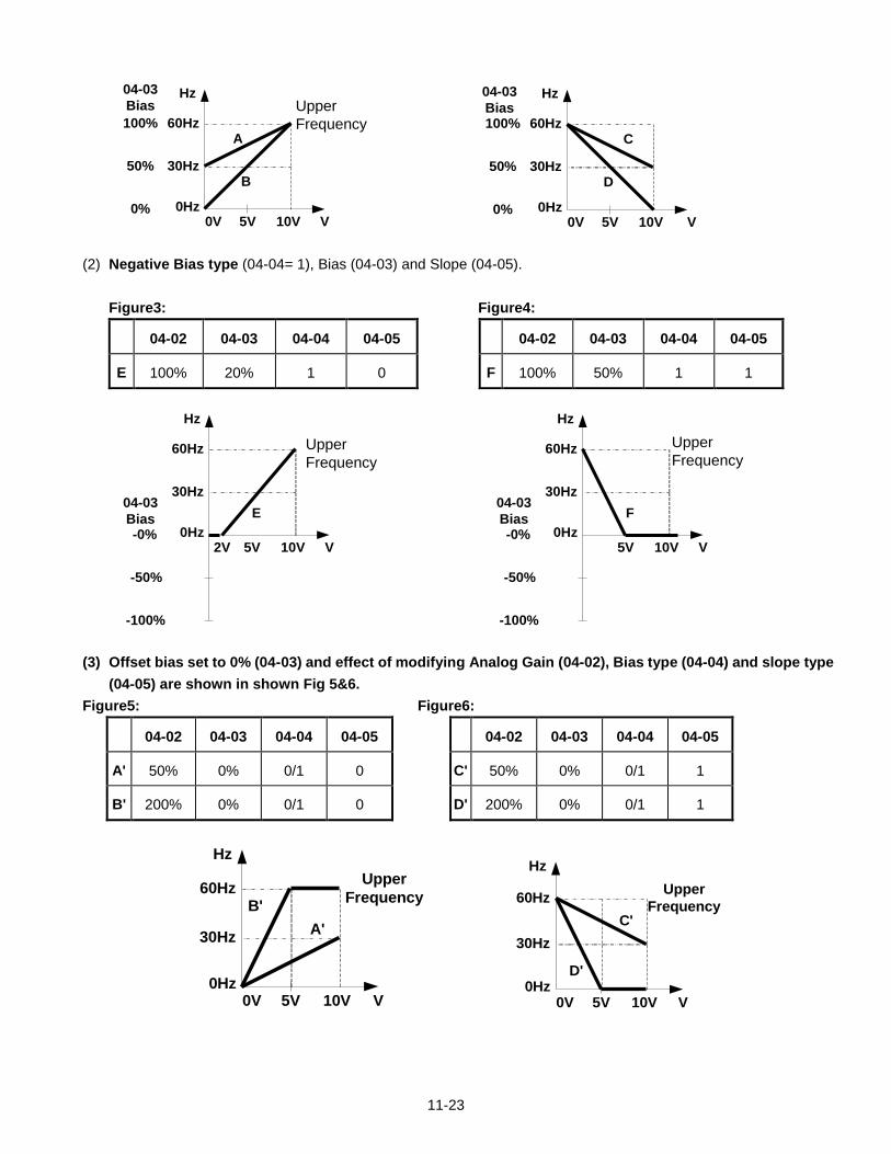
11-23
60Hz
30Hz
0Hz0V 5V 10V
Hz
V
04-03
Bias
100%
50%
0%
Upper
Frequency A
B
60Hz
30Hz
0Hz0V 5V 10V
Hz
V
100%
50%
0%
C
D
04-03
Bias
(2) Negative Bias type (04-04= 1), Bias (04-03) and Slope (04-05).
Figure3: Figure4:
04-02 04-03 04-04 04-05 04-02 04-03 04-04 04-05
E 100% 20% 1 0 F 100% 50% 1 1
60Hz
30Hz
0Hz2V 5V 10V
Hz
V
04-03
Bias
-100%
-50%
-0%
E
Upper
Frequency
60Hz
30Hz
0Hz5V 10V
Hz
V
04-03
Bias
-100%
-50%
-0%
F
Upper
Frequency
(3) Offset bias set to 0% (04-03) and effect of modifying Analog Gain (04-02), Bias type (04-04) and slope type
(04-05) are shown in shown Fig 5&6.
Figure5: Figure6:
04-02 04-03 04-04 04-05 04-02 04-03 04-04 04-05
A' 50% 0% 0/1 0 C' 50% 0% 0/1 1
B' 200% 0% 0/1 0 D' 200% 0% 0/1 1
60Hz
30Hz
0Hz0V 5V 10V
Hz
V
Upper
FrequencyB'
A'
60Hz
30Hz
0Hz0V 5V 10V
Hz
V
Upper
Frequency
D'
C'
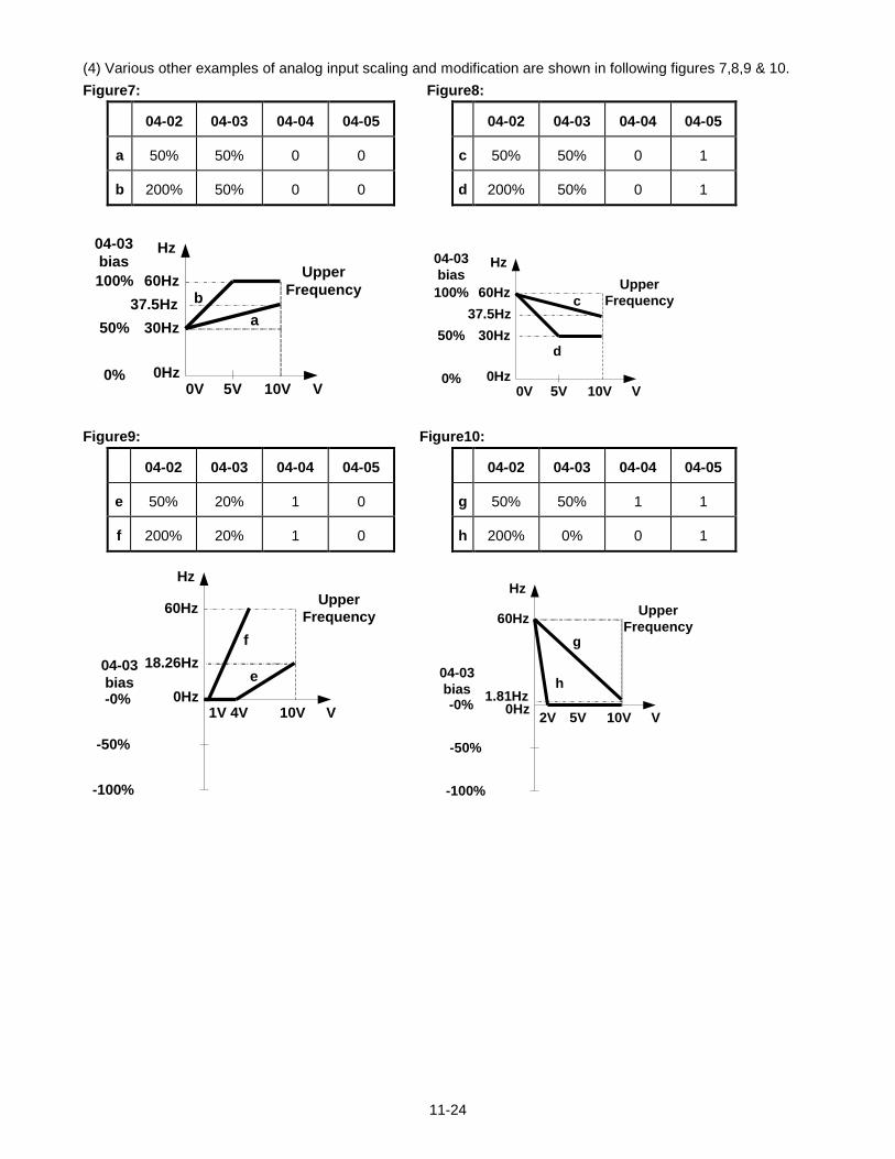
11-24
(4) Various other examples of analog input scaling and modification are shown in following figures 7,8,9 & 10.
Figure7: Figure8:
04-02 04-03 04-04 04-05 04-02 04-03 04-04 04-05
a 50% 50% 0 0 c 50% 50% 0 1
b 200% 50% 0 0 d 200% 50% 0 1
60Hz
30Hz
0Hz0V 5V 10V
Hz
V
04-03
bias
100%
50%
0%
Upper
Frequencyb
a37.5Hz
60Hz
30Hz
0Hz0V 5V 10V
Hz
V
04-03
bias
100%
50%
0%
Upper
Frequencyc
d
37.5Hz
Figure9: Figure10:
04-02 04-03 04-04 04-05 04-02 04-03 04-04 04-05
e 50% 20% 1 0 g 50% 50% 1 1
f 200% 20% 1 0 h 200% 0% 0 1
60Hz
18.26Hz
0Hz1V 4V 10V
Hz
V
04-03
bias
-100%
-50%
-0%
Upper
Frequency
e
f
60Hz
1.81Hz0Hz
2V 10V
Hz
V
04-03
bias
-100%
-50%
-0%
Upper
Frequency
h
5V
g
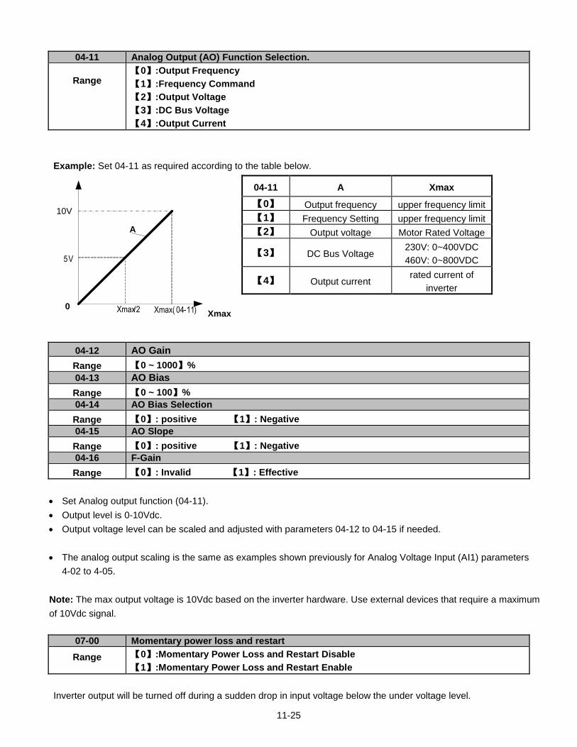
11-25
04-11 Analog Output (AO) Function Selection.
Range
【0】:Output Frequency
【1】:Frequency Command
【2】:Output Voltage
【3】:DC Bus Voltage
【4】:Output Current
Example: Set 04-11 as required according to the table below.
0
10V
Xmax
A
Xmax( 04-11)Xmax/2
5 V
04-12 AO Gain
Range 【0 ~ 1000】%
04-13 AO Bias
Range 【0 ~ 100】%
04-14 AO Bias Selection
Range 【0】: positive 【1】: Negative
04-15 AO Slope
Range 【0】: positive 【1】: Negative
04-16 F-Gain
Range 【0】: Invalid 【1】: Effective
Set Analog output function (04-11).
Output level is 0-10Vdc.
Output voltage level can be scaled and adjusted with parameters 04-12 to 04-15 if needed.
The analog output scaling is the same as examples shown previously for Analog Voltage Input (AI1) parameters
4-02 to 4-05.
Note: The max output voltage is 10Vdc based on the inverter hardware. Use external devices that require a maximum
of 10Vdc signal.
07-00 Momentary power loss and restart
Range
【0】:Momentary Power Loss and Restart Disable
【1】:Momentary Power Loss and Restart Enable
Inverter output will be turned off during a sudden drop in input voltage below the under voltage level.
04-11 A Xmax
【0】 Output frequency upper frequency limit
【1】 Frequency Setting upper frequency limit
【2】 Output voltage Motor Rated Voltage
【3】 DC Bus Voltage 230V: 0~400VDC
460V: 0~800VDC
【4】 Output current rated current of
inverter
11-26
07-00=0: Inverter trips on “UV” fault on power loss and will not restart.
07-00=1: Inverter resumes operation at half of the output frequency before power-loss after power has been
restored. There is no limitation on the number of restarts.
The momentary power loss function is enabled as long as the inverter CPU still has power and the inverter will
restart when power is restored based on the setting of parameters 00-02, 07-04 and status of External run
command.
Caution: After a power loss and Run mode is set to External Run (00-02=1) and Direct start on power up is
enabled (07-04=0) the inverter will automatically start when power is restored.
To ensure safety of operators and to avoid any damages to the machinery, all necessary safety measure must be
taken and an inverter input disconnect switch must be used.
07-01 Auto Restart Delay Time
Range 【0.0~800.0】 s
07-02 Number of Auto Restart Attempts
Range 【0~10】
Automatic restart operation:
07-02=【0】, the inverter will not perform an automatic restart
07-02>【0】, 07-01=【0】
Fault is detected. The inverter turns off the output, displays the fault on the keypad and waits 0.5 sec. before accepting another run / automatic restart command.
07-02>【0】, 07-01>【0】
Active fault is reset and a speed search operation is performed. The time between each fault restart attempt is set by parameter 07-01. When the total number of restart attempts has exceed the number of automatic restart attempts set in parameter 07-02, the inverter will turn off the output and the fault contact is activated.
When the automatic restart function is enabled the internal automatic restart attempt counter is reset based on the following actions:
1. No fault occurs in 10 minutes or longer after the automatic restart 2. Reset command to clear fault via input terminal or using the keypad 3. Power to the inverter is turned off and back on again
11-27
The automatic restart function can be used for the following faults. Please note that when the fault is not listed in
the table the inverter will not attempt an automatic restart.
OC-S Over current at start
OV-C Over voltage during operation / deceleration
PF Input phase loss
OC Over current
OL1 Motor overload
OL2 Motor overload
OL3 Over Torque
LV Low voltage during operation
OVSP Over Speed
LIFE 1 Maintenance required input surge protection circuit
LIFE 2 Maintenance required control Circuit main capacitors
LIFE 3 Maintenance required DC-bus capacitors
Note: Auto restart after a fault will not function during DC injection braking or decelerating to stop.
08-00 Trip Prevention Selection
Range
【xxxx0】:Enable Trip Prevention During Acceleration
【xxxx1】:Disable Trip Prevention During Acceleration
【xxx0x】:Enable Trip Prevention During Deceleration
【xxx1x】:Disable Trip Prevention During Deceleration
【xx0xx】:Enable Trip Prevention in Run Mode
【xx1xx】:Disable Trip Prevention in Run Mode
【x0xxx】:Enable over voltage Prevention in Run Mode
【x1xxx】:Disable over voltage Prevention in Run Mode
08-01 Trip Prevention Level During Acceleration
Range 【50 ~ 200】%
Trip prevention adjustment level during acceleration to prevent over current (OC-A) trips.
If trip prevention during acceleration is enabled and an over current condition occurs due to a heavy load, the
acceleration is put on hold until the output current drops below the setting of parameter 08-01 after which
acceleration resumes.
08-02 Trip Prevention Level During Deceleration
Range 【50 ~ 200】%
Trip prevention adjustment level during deceleration to prevent over Voltage (OV-C) trips.
If trip prevention during deceleration is enabled and an over voltage condition occurs during stopping due to the
load (regenerative energy), deceleration is put on hold until the output current level falls below the setting of
parameter 08-02 after which deceleration resumes.
08-03 Trip Prevention Level During Continuous Run Mode
Range 【50 ~ 200】%
Trip prevention adjustment level during continuous Run to prevent over current (OC-C) trips.
If trip prevention during continuous Run is enabled and an over current occurs due the load such as a sudden
transient load, the output frequency is reduced by decelerating to a lower speed until the over current level falls
11-28
below the setting of parameter 08-0301 after which acceleration resumes back to the target frequency.
08-04 Over Voltage Prevention Level During Run Mode
Range 【350.0VDC~390.0VDC】(230V class) 【700.0VDC~780.0VDC】(460V class)
Over voltage prevention level can be set by parameter 08-04 if needed.
When the DC bus voltage rises above level set in 08-04 an over voltage fault will occur.
08-05 Electronic Motor Overload Protection Operation Mode (OL1)
Range
【0】: Disable
【1】: Enable
The electronic motor overload protection function estimates the motor overload level based on the output current,
output frequency, motor characteristics and time. The motor overload trip time depends on the motor rated
current when the output current is greater than motor FLA.
12-00 Display Mode
Range
0 0 0 0 0
MSD LSD
00000~88888 Each digit can be set from 0 to 8 as listed below.
【0】:Disable display(frequency& parameters)
【1】:output Current
【2】:output Voltage
【3】:DC voltage
【4】:Temperature
【5】:PID feedback
【6】:AI1
【7】:AI2
【8】:Count Status
Note: The highest bit is used for power-up monitor. The 4 least significant bits can be used to customize the
display sequence see chapter 4.1.3.
12-01 PID Feedback Display format
Range
【0】:Displayed in Integer (xxx)
【1】:One Decimal Place (xx.x)
【2】:Two Decimal Places (x.xx)
12-02 PID Feedback Display Unit Setting
Range
【0】:xxx--
【1】:xxxpb(pressure)
【2】:xxxfl(flow)
12-03 Custom Units (Line Speed) Display Mode
Range 【0~65535】Rpm
Set motor rated RPM for the inverter to display the actual motor speed based on the output frequency.
Motor synchronous speed = 120 x Rated frequency ÷ Number of poles.
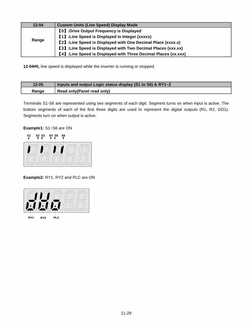
11-29
12-04 Custom Units (Line Speed) Display Mode
Range
【0】:Drive Output Frequency is Displayed
【1】:Line Speed is Displayed in Integer (xxxxx)
【2】:Line Speed is Displayed with One Decimal Place (xxxx.x)
【3】:Line Speed is Displayed with Two Decimal Places (xxx.xx)
【4】:Line Speed is Displayed with Three Decimal Places (xx.xxx)
12-04≠0, line speed is displayed while the inverter is running or stopped.
12-05 Inputs and output Logic status display (S1 to S6) & RY1~2
Range Read only(Panel read only)
Terminals S1-S6 are represented using two segments of each digit. Segment turns on when input is active. The
bottom segments of each of the first three digits are used to represent the digital outputs (R1, R2, DO1).
Segments turn on when output is active.
Example1: S1~S6 are ON
S1 S2 S3 S4 S5 S6
Example2: RY1, RY2 and PLC are ON
RY1 RY2 PLC
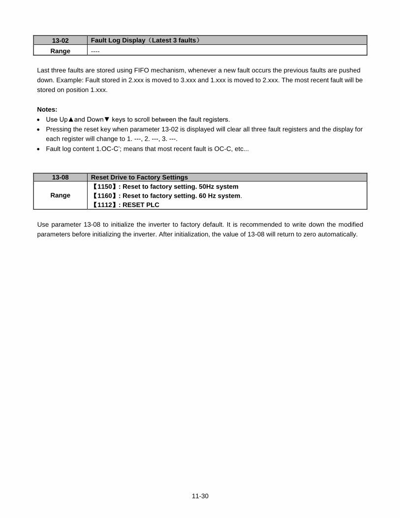
11-30
13-02 Fault Log Display(Latest 3 faults)
Range ----
Last three faults are stored using FIFO mechanism, whenever a new fault occurs the previous faults are pushed
down. Example: Fault stored in 2.xxx is moved to 3.xxx and 1.xxx is moved to 2.xxx. The most recent fault will be
stored on position 1.xxx.
Notes:
Use Upand Down keys to scroll between the fault registers.
Pressing the reset key when parameter 13-02 is displayed will clear all three fault registers and the display for
each register will change to 1. ---, 2. ---, 3. ---.
Fault log content 1.OC-C’; means that most recent fault is OC-C, etc...
13-08 Reset Drive to Factory Settings
Range
【1150】: Reset to factory setting. 50Hz system
【1160】: Reset to factory setting. 60 Hz system.
【1112】: RESET PLC
Use parameter 13-08 to initialize the inverter to factory default. It is recommended to write down the modified
parameters before initializing the inverter. After initialization, the value of 13-08 will return to zero automatically.
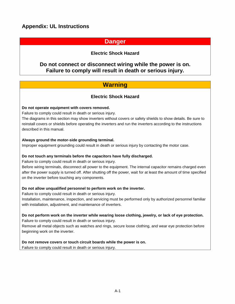
A-1
Appendix: UL Instructions
Danger
Electric Shock Hazard
Do not connect or disconnect wiring while the power is on. Failure to comply will result in death or serious injury.
Warning
Electric Shock Hazard
Do not operate equipment with covers removed.
Failure to comply could result in death or serious injury.
The diagrams in this section may show inverters without covers or safety shields to show details. Be sure to
reinstall covers or shields before operating the inverters and run the inverters according to the instructions
described in this manual.
Always ground the motor-side grounding terminal.
Improper equipment grounding could result in death or serious injury by contacting the motor case.
Do not touch any terminals before the capacitors have fully discharged.
Failure to comply could result in death or serious injury.
Before wiring terminals, disconnect all power to the equipment. The internal capacitor remains charged even
after the power supply is turned off. After shutting off the power, wait for at least the amount of time specified
on the inverter before touching any components.
Do not allow unqualified personnel to perform work on the inverter.
Failure to comply could result in death or serious injury.
Installation, maintenance, inspection, and servicing must be performed only by authorized personnel familiar
with installation, adjustment, and maintenance of inverters.
Do not perform work on the inverter while wearing loose clothing, jewelry, or lack of eye protection.
Failure to comply could result in death or serious injury.
Remove all metal objects such as watches and rings, secure loose clothing, and wear eye protection before
beginning work on the inverter.
Do not remove covers or touch circuit boards while the power is on.
Failure to comply could result in death or serious injury.
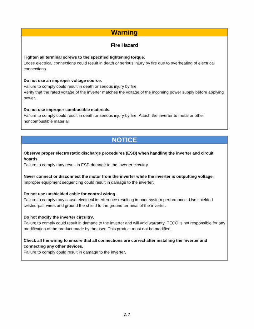
A-2
Warning
Fire Hazard
Tighten all terminal screws to the specified tightening torque.
Loose electrical connections could result in death or serious injury by fire due to overheating of electrical
connections.
Do not use an improper voltage source.
Failure to comply could result in death or serious injury by fire.
Verify that the rated voltage of the inverter matches the voltage of the incoming power supply before applying
power.
Do not use improper combustible materials.
Failure to comply could result in death or serious injury by fire. Attach the inverter to metal or other
noncombustible material.
NOTICE
Observe proper electrostatic discharge procedures (ESD) when handling the inverter and circuit
boards.
Failure to comply may result in ESD damage to the inverter circuitry.
Never connect or disconnect the motor from the inverter while the inverter is outputting voltage.
Improper equipment sequencing could result in damage to the inverter.
Do not use unshielded cable for control wiring.
Failure to comply may cause electrical interference resulting in poor system performance. Use shielded
twisted-pair wires and ground the shield to the ground terminal of the inverter.
Do not modify the inverter circuitry.
Failure to comply could result in damage to the inverter and will void warranty. TECO is not responsible for any
modification of the product made by the user. This product must not be modified.
Check all the wiring to ensure that all connections are correct after installing the inverter and
connecting any other devices.
Failure to comply could result in damage to the inverter.
A-3
UL Standards
The UL/cUL mark applies to products in the United States and Canada and it means that UL has performed
product testing and evaluation and determined that their stringent standards for product safety have been met.
For a product to receive UL certification, all components inside that product must also receive UL certification.
UL Standards Compliance
This inverter is tested in accordance with UL standard UL508C and complies with UL requirements. To ensure
continued compliance when using this inverter in combination with other equipment, meet the following
conditions:
Installation Area
Do not install the inverter to an area greater than pollution severity 2 (UL standard).
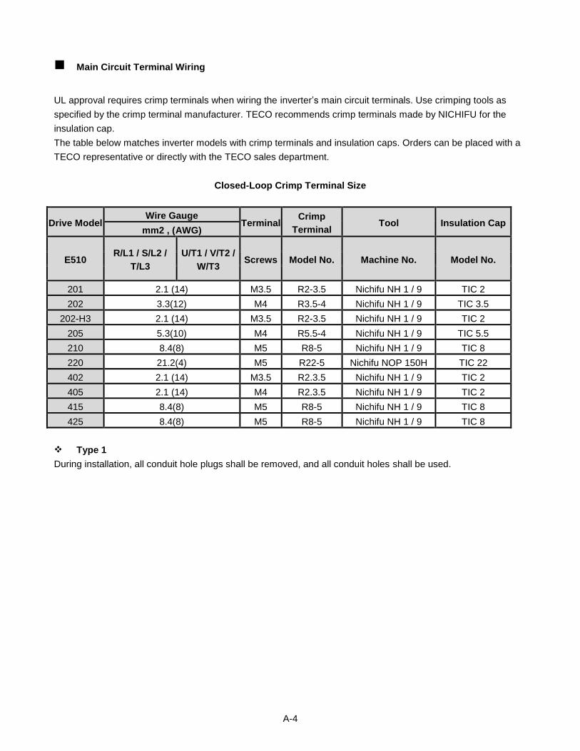
A-4
Main Circuit Terminal Wiring
UL approval requires crimp terminals when wiring the inverter’s main circuit terminals. Use crimping tools as
specified by the crimp terminal manufacturer. TECO recommends crimp terminals made by NICHIFU for the
insulation cap.
The table below matches inverter models with crimp terminals and insulation caps. Orders can be placed with a
TECO representative or directly with the TECO sales department.
Closed-Loop Crimp Terminal Size
Drive Model Wire Gauge
Terminal Crimp
Terminal Tool Insulation Cap
mm2 , (AWG)
E510 R/L1 / S/L2 /
T/L3
U/T1 / V/T2 /
W/T3 Screws Model No. Machine No. Model No.
201 2.1 (14) M3.5 R2-3.5 Nichifu NH 1 / 9 TIC 2
202 3.3(12) M4 R3.5-4 Nichifu NH 1 / 9 TIC 3.5
202-H3 2.1 (14) M3.5 R2-3.5 Nichifu NH 1 / 9 TIC 2
205 5.3(10) M4 R5.5-4 Nichifu NH 1 / 9 TIC 5.5
210 8.4(8) M5 R8-5 Nichifu NH 1 / 9 TIC 8
220 21.2(4) M5 R22-5 Nichifu NOP 150H TIC 22
402 2.1 (14) M3.5 R2.3.5 Nichifu NH 1 / 9 TIC 2
405 2.1 (14) M4 R2.3.5 Nichifu NH 1 / 9 TIC 2
415 8.4(8) M5 R8-5 Nichifu NH 1 / 9 TIC 8
425 8.4(8) M5 R8-5 Nichifu NH 1 / 9 TIC 8
Type 1
During installation, all conduit hole plugs shall be removed, and all conduit holes shall be used.
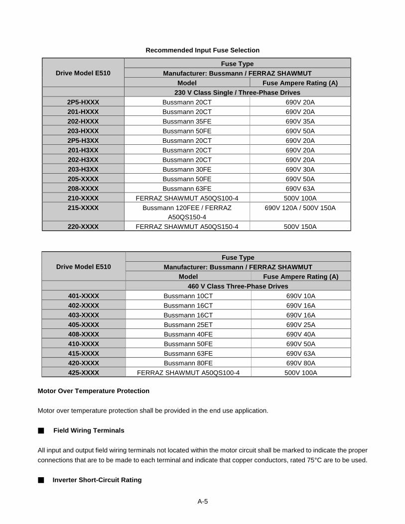
A-5
Recommended Input Fuse Selection
Drive Model E510
Fuse Type
Manufacturer: Bussmann / FERRAZ SHAWMUT
Model Fuse Ampere Rating (A)
230 V Class Single / Three-Phase Drives
2P5-HXXX Bussmann 20CT 690V 20A
201-HXXX Bussmann 20CT 690V 20A
202-HXXX Bussmann 35FE 690V 35A
203-HXXX Bussmann 50FE 690V 50A
2P5-H3XX Bussmann 20CT 690V 20A
201-H3XX Bussmann 20CT 690V 20A
202-H3XX Bussmann 20CT 690V 20A
203-H3XX Bussmann 30FE 690V 30A
205-XXXX Bussmann 50FE 690V 50A
208-XXXX Bussmann 63FE 690V 63A
210-XXXX FERRAZ SHAWMUT A50QS100-4 500V 100A
215-XXXX Bussmann 120FEE / FERRAZ
A50QS150-4
690V 120A / 500V 150A
220-XXXX FERRAZ SHAWMUT A50QS150-4 500V 150A
Drive Model E510
Fuse Type
Manufacturer: Bussmann / FERRAZ SHAWMUT
Model Fuse Ampere Rating (A)
460 V Class Three-Phase Drives
401-XXXX Bussmann 10CT 690V 10A
402-XXXX Bussmann 16CT 690V 16A
403-XXXX Bussmann 16CT 690V 16A
405-XXXX Bussmann 25ET 690V 25A
408-XXXX Bussmann 40FE 690V 40A
410-XXXX Bussmann 50FE 690V 50A
415-XXXX Bussmann 63FE 690V 63A
420-XXXX Bussmann 80FE 690V 80A
425-XXXX FERRAZ SHAWMUT A50QS100-4 500V 100A
Motor Over Temperature Protection
Motor over temperature protection shall be provided in the end use application.
Field Wiring Terminals
All input and output field wiring terminals not located within the motor circuit shall be marked to indicate the proper
connections that are to be made to each terminal and indicate that copper conductors, rated 75°C are to be used.
Inverter Short-Circuit Rating
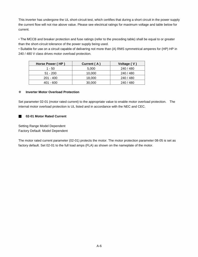
A-6
This inverter has undergone the UL short-circuit test, which certifies that during a short circuit in the power supply
the current flow will not rise above value. Please see electrical ratings for maximum voltage and table below for
current.
• The MCCB and breaker protection and fuse ratings (refer to the preceding table) shall be equal to or greater
than the short-circuit tolerance of the power supply being used.
• Suitable for use on a circuit capable of delivering not more than (A) RMS symmetrical amperes for (HP) HP in
240 / 480 V class drives motor overload protection.
Horse Power ( HP ) Current ( A ) Voltage ( V )
1 - 50 5,000 240 / 480
51 - 200 10,000 240 / 480
201 - 400 18,000 240 / 480
401 - 600 30,000 240 / 480
Inverter Motor Overload Protection
Set parameter 02-01 (motor rated current) to the appropriate value to enable motor overload protection. The
internal motor overload protection is UL listed and in accordance with the NEC and CEC.
02-01 Motor Rated Current
Setting Range Model Dependent
Factory Default: Model Dependent
The motor rated current parameter (02-01) protects the motor. The motor protection parameter 08-05 is set as
factory default. Set 02-01 to the full load amps (FLA) as shown on the nameplate of the motor.
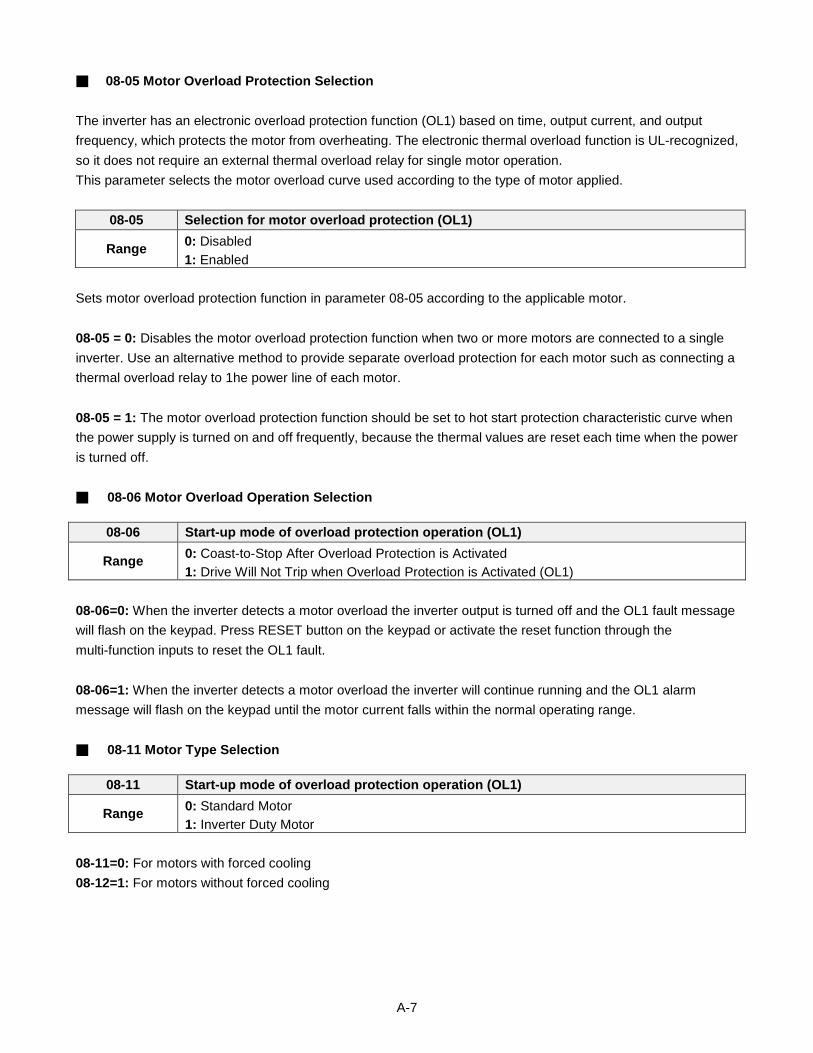
A-7
08-05 Motor Overload Protection Selection
The inverter has an electronic overload protection function (OL1) based on time, output current, and output
frequency, which protects the motor from overheating. The electronic thermal overload function is UL-recognized,
so it does not require an external thermal overload relay for single motor operation.
This parameter selects the motor overload curve used according to the type of motor applied.
08-05 Selection for motor overload protection (OL1)
Range 0: Disabled
1: Enabled
Sets motor overload protection function in parameter 08-05 according to the applicable motor.
08-05 = 0: Disables the motor overload protection function when two or more motors are connected to a single
inverter. Use an alternative method to provide separate overload protection for each motor such as connecting a
thermal overload relay to 1he power line of each motor.
08-05 = 1: The motor overload protection function should be set to hot start protection characteristic curve when
the power supply is turned on and off frequently, because the thermal values are reset each time when the power
is turned off.
08-06 Motor Overload Operation Selection
08-06 Start-up mode of overload protection operation (OL1)
Range 0: Coast-to-Stop After Overload Protection is Activated
1: Drive Will Not Trip when Overload Protection is Activated (OL1)
08-06=0: When the inverter detects a motor overload the inverter output is turned off and the OL1 fault message
will flash on the keypad. Press RESET button on the keypad or activate the reset function through the
multi-function inputs to reset the OL1 fault.
08-06=1: When the inverter detects a motor overload the inverter will continue running and the OL1 alarm
message will flash on the keypad until the motor current falls within the normal operating range.
08-11 Motor Type Selection
08-11 Start-up mode of overload protection operation (OL1)
Range 0: Standard Motor
1: Inverter Duty Motor
08-11=0: For motors with forced cooling
08-12=1: For motors without forced cooling
A-8
08-12 Motor Overload Protection Curve
08-12 Start-up mode of overload protection operation (OL1)
Range 0: Motor Overload Protection for General loads (OL=103 %) (150% for 1 Minute)
1: Motor Over load Protection for HVAC (Fan & Pump) (OL=113%) (123% for 1 Minute)
08-12=0: For constant torque applications with a load less than 103% of the motor rated current. If the load is
greater than 150% of the motor rated current, the motor will run for 1 minute before faulting on motor overload.
08-12=1: For variable torque applications (Fan, Pumps…) with a load less than 113% of the motor rated current.
If the load is greater than 123% of the motor rated current, the motor will run for 1 minute before faulting on motor
overload.
Teco-Westinghouse Motor Company5100 N. IH-35Round Rock, Texas 786811-800-279-4007www.tecowestinghouse.com Ver 01: 2015.08
Distributor
E510INVERTER