Embed Size (px)
Citation preview

----
----
DISCOVERY NM 530C
CPC
GE Healthcare
GE does not take responsibility for any damages resulting from changes on drawings made by others. Errors may occur by not referring to the completeset of final issue drawing. GE cannot accept responsibility for any damage due to the partial use of GE final issue drawings, however caused. Alldimensions are in millimeters unless otherwise specified. Do not scale from printed pdf files. GE accepts no responsibility or liability for defective work
due to scaling from these drawings. /14EN-NUC-TYP-DISCOVERY_NM_530C-WEB.DWG
----
----
PMM 5454095-1EN
----
1/4"=1'-0"
-
11/Feb/2022
Typical
A mandatory component of this drawing set is the GE Healthcare Pre Installation manual. Failure to reference the Pre Installation manual will result inincomplete documentation required for site design and preparation.
Pre Installation documents for GE Healthcare products can be accessed on the web at: www.gehealthcare.com/siteplanning -
Drawn by Verified by PIM Manual
SheetFormat
Concession
Scale DateFile Name
RevS.O. (GON)
A3
1
REV DATE MODIFICATIONS
FINAL STUDY
01
01 - C1 - Cover Sheet 02 - C2 - Disclaimer - Site Readiness 03 - A1 - General Notes 04 - A2 - Equipment Layout 05 - A3 - Equipment Details 06 - A4 - Delivery 07 - S1 - Structural Notes 08 - S2 - Structural Layout 09 - S3 - Structural Details
10 - M1 - HVAC 11 - E1 - Electrical Notes 12 - E2 - Electrical Layout 13 - E3 - Elevations-Interconnections 14 - E4 - Power Requirements

GLOBAL SITE READINESS CHECKLIST (DI)DOC1809666 Rev. 7
Site Ready Checks at Installation
EHS Site Requirements
Overall access route to the scan room free from obstruction / high hazards.Enough space to store tools, equipment, parts, install waste and the general area free from obstruction and trip hazards.
Enough necessary facilities for the GE employees available.
No 3rd parties working in the area that may affect the safety of the installation activity.
Area free from any chemical, gas, dust, welding fume exposure and has painting been completed and dry.
All emergency routes identified, signed and clear from obstruction.
Accessible single source lockable panel that LOTO can be applied to for GE equipment installation (MDP and/or PDU).There are no other conditions or hazards that you have observed or have been made aware of by the customer or contractors on site.
Required for Mechanical Install start
Room dimensions, including ceiling height, for all Exam, Equipment/Technical & Control rooms meets GE specifications.
Ceiling support structure, if indicated on the GE drawing, is in the correct location and at the correct height according to the OriginalEquipment Manufacturer specifications.
Levelness and spacing has been measured, and is ready for the installation of any GE supplied components.
Overhead support Structure (unistrut) has been confirmed with customer/contractor to meet required GE provided criteria.Finished ceiling is installed. If applicable ceiling tiles installed per PMI discretion.
Floor levelness/flatness is measured and within tolerance, and there are no visible defects per GEHC specifications.Entry door threshold meets PIM requirement
Floor Strength and thickness have been discussed with customer/contractor and they have confirmed GE requirements are met.
Rooms that will contain equipment, including staging areas if applicable, are construction debris free. Precautions must be taken to preventdebris from entering rooms containing equipment.
Cable ways (floor/wall/ceiling/Access Flooring) are available for installation of GE cables are of correct length and diameter.
Cable ways routes per GE Final drawings and cable access openings areas installed at a time determined by GEHC PM. Surface floor duct canbe installed at time of system installation.
Adequate room illumination installed and working.
Customer supplied countertops where GE equipment will be installed are in place.
Nuclear Medicine systems levelness measurement survey must be provided to GE prior the delivery.
Required for Calibration start
HVAC systems Installed, and the site meets minimum environmental operational system requirements.
System power & grounding (PDB/MDP) is available as per GE specifications.
System power & grounding (PDB/MDP) is installed at point of final connection and ready to use. Lock Out Tag Out is available.PMI to confirm all feeder wires and breaker are size appropriately. EPO installed if needed.
PMI to confirm with electrician all power and signal cables are well terminated ensuring there are no loose connections.
Network outlets installed.Computer network available and working.
Site has license for using/importing radioactive sources and a Hot Lab is available. Radioactive Sources should be available for systemcalibration during installation.
Lead doors and windows complete or scheduled to be installed. If applicable, radiation protection (shielding) finished & radioprotectionregulatory approval for installation obtained.
Note: The details shown here are only an extract from DOC1809666. For the complete document please contact your PMI.
GENERAL SPECIFICATIONS
· GE is not responsible for the installation of developers and associated equipment, lighting, cassette trays andprotective screens or derivatives not mentioned in the order.
· The final study contains recommendations for the location of GE equipment and associated devices, electricalwiring and room arrangements. When preparing the study, every effort has been made to consider everyaspect of the actual equipment expected to be installed.
· The layout of the equipment offered by GE, the dimensions given for the premises, the details provided forthe pre-installation work and electrical power supply are given according to the information noted duringon-site study and the wishes expressed by the customer.
· The room dimensions used to create the equipment layout may originate from a previous layout and may notbe accurate as they may not have been verified on site. GE cannot take any responsibility for errors due tolack of information.
· Dimensions apply to finished surfaces of the room.· Actual configuration may differ from options presented in some typical views or tables.· If this set of final drawings has been approved by the customer, any subsequent modification of the site must
be subject to further investigation by GE about the feasibility of installing the equipment. Any reservationsmust be noted.
· The equipment layout indicates the placement and interconnection of the indicated equipment components. There may be local requirements that could impact the placement of these components. It remains thecustomer's responsibility to ensure that the site and final equipment placement complies with all applicablelocal requirements.
· All work required to install GE equipment must be carried out in compliance with the building regulations andthe safety standards of legal force in the country concerned.
· These drawings are not to be used for actual construction purposes. The company cannot take responsibilityfor any damage resulting therefrom.
CUSTOMER RESPONSIBILITIES
· It is the responsibility of the customer to prepare the site in accordance with the specifications stated in thefinal study. A detailed site readiness checklist is provided by GE. It is the responsibility of the customer toensure all requirements are fulfilled and that the site conforms to all specifications defined in the checklist and final study. The GE Project Manager of Installation (PMI) will work in cooperation with the customer to followup and ensure that actions in the checklist are complete, and if necessary, will aid in the rescheduling of thedelivery and installation date.
· Prior to installation, a structrual engineer of record must ensure that the floor and ceiling is designed in such away that the loads of the installed system can be securely borne and transferred. The layout of additionalstructural elements, dimensioning and the selection of appropriate installation methods are the soleresponsibility of the structural engineer. Execution of load bearing structures supporting equipment on theceiling, floor or walls are the customer's responsibility.
RADIO-PROTECTION
· Suitable radiological protection must be determined by a qualified radiological physicist in conformation withlocal regulations. GE does not take responsibility for the specification or provision of radio-protection.
DISCLAIMER
THE UNDERSIGNED, HEREBY CERTIFIES THAT I HAVE READ AND APPROVED THE PLANS IN THIS DOCUMENT.
DATE NAME SIGNATURE
DateRev /14EN-NUC-TYP-DISCOVERY_NM_530C-WEB.DWG A 11/Feb/2022DISCOVERY NM 530CTypical C2 - Disclaimer - Site Readiness 02-

In order to avoid interference on the system, the static field limits from the surrounding environment must beless than 1 Gauss in both the scan and the operator rooms.
In order to avoid interference on the system, static field limits from the surrounding environment are specifiedbelow.· Static field must be less than 1 Gauss in Examination room, and in the Control Area.· Static field must be less than 3 Gauss in the Technical Room.
ENVIRONMENT
In order to reduce electrostatic discharge interference, install a charge dissipative floor material to avoidelectrostatic charge buildup.The relative humidity shall be at least 30 percent.The dissipative material shall be connected to the system ground reference, if applicable.
MAGNETIC FIELD SPECIFICATIONS
ELECTROSTATIC DISCHARGE ENVIRONMENT & RECOMMENDATIONS
This system complies with IEC60601-1-2 (2007-03) EMC standard for medical electrical equipment.
EMC COMPLIANCE
RADIOACTIVE ISOTOPES
Since this equipment involves the use of radioactive isotopes, compliance with Nuclear Regulatory Commissionregulations, or similar regulatory requirements (depending on the country), must be adhered to.In most situations, this must be done prior to acquiring any source materials. This includes calibration sourceswhich may have fairly long delivery lead times. These calibration sources may also have a short half life, and itmay not be advisable to store them over long periods of time.Regulatory compliance should be arranged early in the site planning process.
USING RADIOACTIVE ISOTOPES
RADIOACTIVE ISOTOPES FOR SYSTEM CALIBRATION
A Co57 Square Flood Source for QC and Maps creation, with an activity of 20 mCi, must be pre-ordered andavailable on site before installation commences.
· Any deviation from these drawings must be communicated in writing to and reviewed by your local GEhealthcare installation project manager prior to making changes.
· Make arrangements for any rigging, special handling, or facility modifications that must be made to deliverthe equipment to the installation site. If desired, your local GE healthcare installation project manager cansupply a reference list of rigging contractors.
· New construction requires the following;1. Secure area for equipment,2. Power for drills and other test equipment,3. Capability for image analysis,4. Restrooms.
· Provide for refuse removal and disposal (e.g. crates, cartons, packing)
· For CT, MR, PET/CT, and SPECT systems it is required to minimize vibrations within the scan room. It is thecustomer's responsibility to contract a vibration consultant/engineer to implement site design modificationsto meet the GE vibration specification. Refer to the system preinstallation manual for vibration specifications.
CUSTOMER SITE READINESS REQUIREMENTS
DateRev /14EN-NUC-TYP-DISCOVERY_NM_530C-WEB.DWG A 11/Feb/2022DISCOVERY NM 530CTypical A1 - General Notes 03

For Accessory Sales: (866) 281-7545 Options 1, 2, 1, 2 or mail to: [email protected]
Exam room height
Finished floor to slab height
Recommended finished ceiling heightTBD
8'-0"
BY ITEM DESCRIPTIONMAX HEAT
OUTPUT(btu)
WEIGHT(lbs)
MAXHEAT
OUTPUT(W)
WEIGHT(kg)
A 1 Gantry 2150 1433 630 650
A 2 Integrated Power Supply 205 172 60 78
A 3 Patient table 510 573 150 260
A 4 Operators console on cart 273 33 80 15
A 5 Acquisition computer 510 287 150 130
A 6 Patient Positioning Monitor 102 - 30 -
A 7 Patient Positioning Camera - - - -
D 8 UPS system 4436 33 1300 15
C 9 Main Disconnect
C 10 Minimum opening for equipment delivery is 36 in. w x 83 in. h, contingent on a 53 in.corridor width
DateRev /14EN-NUC-TYP-DISCOVERY_NM_530C-WEB.DWG A 11/Feb/2022DISCOVERY NM 530CTypical A2 - Equipment Layout 041/4"=1'-0"
EXAM ROOM
1
2
3
9 6
710
58 4
3'-7"
14'-1"4'
-6"
11'-1
1"
LEGEND
A GE Supplied D Available from GEB GE Supplied/contractor installed E Equipment existing in room
C Customer/contractor supplied and installed * Item to be reinstalled from another site

GANTRY AND PATIENT TABLE
SIDE VIEW
2650[104 in]
PATIENT TABLE
FRONT VIEWSIDE VIEW
914
[36
in]
416[16 in]
1600[63 in]
1980[78 in] 560
[22 in]
AQUISITION STATION ON CART (AC2)
TOP VIEWSIDE VIEWS
1720
[68
in]
700
[28
in]
IPS
SIDE VIEWREAR VIEWFRONT VIEW TOP VIEW
min
. 120
0[m
in. 4
7 in
]
500[20 in]
65[3 in]
610[24 in]
400 [16 in]
550 [22 in]
550
[22
in]
520[20 in]
500
[20
in]
DateRev /14EN-NUC-TYP-DISCOVERY_NM_530C-WEB.DWG A 11/Feb/2022DISCOVERY NM 530CTypical A3 - Equipment Details 05

DELIVERY
UNPACKED COMPONENT DIMESIONSEQUIPMENT DIMENSIONS WEIGHT
GANTRY WITHOUT TRIPLETS
LENGTH 735 mm [28.9 in]590 kg [1300 lb]WIDTH 1350 mm [53 in]
HEIGHT 1550 mm [61 in]
GANTRY-FULL CONFIGURATIONWITH TRIPLETS
LENGTH 735 mm [28.9 in]650 kg [1433 lb]WIDTH 1350 mm [53 in]
HEIGHT 1550 mm [61 in]
PATIENT TABLE
LENGTH 1400 mm [55 in]260 kg [573 lb]WIDTH 550 mm [21.6 in]
HEIGHT 550 mm [21.6 in]
THE CUSTOMER/CONTRACTOR SHOULD:
· Provide an area adjacent to the installation site for delivery and unloading of the GE equipment.· Ensure that the dimensions of all doors, corridors, ceiling heights are sufficient to accommodate the
movement of GE equipment from the delivery area into the definitive installation room.· Ensure that access routes for equipment will accommodate the weights of the equipment and any
transportation, lifting and rigging equipment.· Ensure that all necessary arrangements for stopping and unloading on public or private property not
belonging to the customer have been made.
DateRev /14EN-NUC-TYP-DISCOVERY_NM_530C-WEB.DWG A 11/Feb/2022DISCOVERY NM 530CTypical A4 - Delivery 06

STRUCTURAL NOTES
· All units that are wall mounted or wall supported are to be provided with supports where necessary. Wallsupports are to be supplied and installed by the customer or his contractors. See plan and detail sheets forsuggested locations and mounting hole locations.
· Floor slabs on which equipment is to be installed must be flat and level to specifications.
· Dimensions are to finished surfaces of room.
· For seismic regions ensure supports span three members.
· Customers contractor must provide all penetrations in post tension floors.
· Customers contractor must provide and install any non-standard anchoring. Documents for standard anchoringmethods are included with GE equipment drawings for geographic areas that require such documentation.
· Customers contractor must provide and install hardware for "through the floor" anchoring and/or any bracingunder access floors. This contractor must also provide floor drilling that cannot be completed because of anobstruction encountered while drilling by the GE installer such as rebar etc.
· It is the customer's responsibility to perform any floor or wall penetrations that may be required. The customeris also responsible for ensuring that no subsurface utilities (e.g., electrical or any other form of wiring, conduits,piping, duct work or structural supports (i.e. post tension cables or rebar)) will interfere or come in contact withsubsurface penetration operations (e.g. drilling and installation of anchors/screws) performed during theinstallation process. To ensure worker safety, GE installers will perform surface penetration operations onlyafter the customer's validation and completion of the "GE surface penetration permit"
DateRev /14EN-NUC-TYP-DISCOVERY_NM_530C-WEB.DWG A 11/Feb/2022DISCOVERY NM 530CTypical S1 - Structural Notes 07
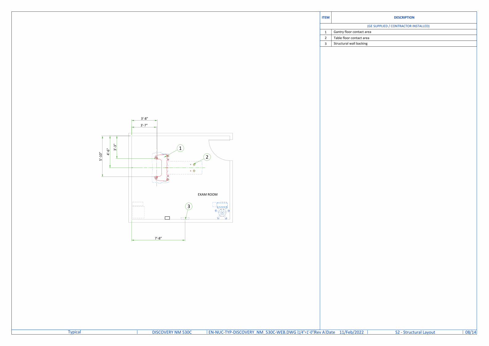
ITEM DESCRIPTION
(GE SUPPLIED / CONTRACTOR INSTALLED)
1 Gantry floor contact area
2 Table floor contact area3 Structural wall backing
DateRev /14EN-NUC-TYP-DISCOVERY_NM_530C-WEB.DWG A 11/Feb/2022DISCOVERY NM 530CTypical S2 - Structural Layout 081/4"=1'-0"
EXAM ROOM
1
2
3
3'-8"
4'-6
"
3'-7"
3'-3
"
5'-1
0"
7'-8"

FLOOR SPECIFICATIONS
· The floor must be capable of supporting the weight of the equipment and accessories.· When the floor does not meet level and flatness specifications, the floor will need to be corrected. The entire
area of the installation room should be leveled.· No fill material is allowed as a patch to compensate for surface deviations. Patches will eventually crack and
pop out.
FLOOR LOADING
FLOOR LEVELING SPECIFICATIONSSlope ±30 mm [±1 3/16 in] over 4300 mm [170 in]
Flatness
Surface should be smooth and have nomore than 5 mm [3/16 in] deviation in any1520 mm [60 in] throughout the room or
system installation area
Floor surface Floor should have one single poured surface
510[20 in]
1147[45 in]
Center of gravity
LOADING DISTRIBUTION TO THE FLOOR
54 [2 in]
510
[20
in]
510
[20
in]
135
[5 in
]13
5[5
in]
450
[18
in]
450
[18
in]
Table legs (Ø80 [Ø3.1 in])152.0 daN per padincluding 78.5 daN forpatient
Gantry-Table legs (Ø76 [Ø3 in])418.7 daN per pad including78.5 daN for patient
Gantry weight: 650 kg [1433 lb]Table weight: 320 kg [705 lb]
Gantry legs (Ø76 [Ø3 in])335.3 daN per pad including
127.4 daN for patient
DateRev /14EN-NUC-TYP-DISCOVERY_NM_530C-WEB.DWG A 11/Feb/2022DISCOVERY NM 530CTypical S3 - Structural Details 09

AIR RENEWALAccording to local standards.
EXAM/CONTROL ROOM
TemperatureMin Max
18 °C [64 °F] 25 °C [77 °F]
Temperature gradient ≤ 3 °C/h [≤ 5.4 °F/h]Relative humidity (1) 40% to 60%Humidity gradient ≤ 5%/h
NOTEIn case of using air conditioning systems that have a risk of water leakage it is recommended not to install it above electric equipment or totake measures to protect the equipment from dropping water.
TEMPERATURE AND HUMIDITY SPECIFICATIONS
STORAGE CONDITIONS
IN-USE CONDITIONS
System without Detector Triplets Detector TripletsTemperature -20°C to +60°C [-4°F to 140°F] +10°C to +30°C [50°F to 86°F]
Relative humidity (1) 15% to 90%Humidity gradient ≤ 5%/hAir pressure 700 hPA to 1060 hPa
(1) non condensing
ROOM DESCRIPTIONHEAT DISSIPATION
(kW)HEAT DISSIPATION
(BTU/hr)
MAX MAX
Exam Room
Gantry 0.63 2150
Chiller 0.30 1020
Patient table 0.15 510
IPS 0.06 205Acquisition station 0.15 510
Monitor 0.08 2732 kVA UPS (E4502K) 1.30 4436
TOTAL 2.67 9104
HEAT DISSIPATION
DateRev /14EN-NUC-TYP-DISCOVERY_NM_530C-WEB.DWG A 11/Feb/2022DISCOVERY NM 530CTypical M1 - HVAC 10

CONNECTIVITY REQUIREMENTS
Your new GE Healthcare imaging modality will require local and remote connectivity to enable our full range ofdigital support:
· Local connectivity - This allows your system to connect to local devices such as PACS and modality worklist.We will require network information to configure the system(s), and a live ethernet port(s) prior to thedelivery of the system(s).
· Remote connectivity - Your GE Healthcare service warranty includes InSite™ (applicable to InSite capableproducts), a powerful broadband-based service which enables digital tools that can help guard yourhospital against equipment downtime and revenue loss by quickly connecting you to a GE Healthcareexpert.
Depending on product family and software version, imaging systems can be connected in one of the followingmethods:
1. TLS over TCP Port 443 (Preferred method for new products) via:a. DNS resolutionb. Customer-provided Proxy orc. GE Proxy (Available in some regions)
2. Site-to-Site IPsec VPN tunnel Please provide the GE project manager with the contact information for the resource that can provide informationrequired to set up these connections. GEHC will send out communication to these contacts, which will include theproject's Connectivity requirements, and a Connectivity form. This form will need to be completed and returned toGEHC prior to delivery of the system to ensure the system is tested and connectivity is enabled prior to thecompletion of the installation.
ELECTRICAL NOTES
· All junction boxes, conduit, duct, duct dividers, switches, circuit breakers, cable tray, etc., are to be suppliedand installed by customers electrical contractor.
· Conduit and duct runs shall have sweep radius bends· Conduits and duct above ceiling or below finished floor must be installed as near to ceiling or floor as possible
to reduce run length.· Ceiling mounted junction boxes illustrated on this plan must be installed flush with finished ceiling.· All ductwork must meet the following requirements:
1.Ductwork shall be metal with dividers and have removable, accessible covers.2.Ductwork shall be certified/rated for electrical power purposes.3.Ductwork shall be electrically and mechanically bonded together in an approved manner.4.PVC as a substitute must be used in accordance with all local and national codes.
· All openings in raceway and access flooring are to be cut out and finished off with grommet material by thecustomers contractor.
· General contractor to insert pull cords for all cable run conduits between the equipment room and theoperators control room.
· 10 foot pigtails at all junction points.· Grounding is critical to equipment function and patient safety. Site must conform to wiring specifications
shown on this plan.
1. All wires specified shall be copper stranded, flexible, thermo-plastic, color coded, cut 10 foot long at outletboxes, duct termination points or stubbed conduit ends. All conductors, power, signal and ground, must berun in a conduit or duct system. Electrical contractor shall ring out and tag all wires at both ends. Wire runsmust be continuous copper stranded and free from splices.
1.1. Aluminum or solid wires are not allowed.2. Wire sizes given are for use of equipment. Larger sizes may be required by local codes.3. It is recommended that all wires be color coded, as required in accordance with national and local electrical
codes.4. Conduit sizes shall be verified by the architect, electrical engineer or contractor, in accordance with local or
national codes.5. Convenience outlets are not illustrated. Their number and location are to be specified by others. Locate at
least one convenience outlet close to the system control, the power distritbution unit and one on each wall ofthe procedure room. Use hospital approved outlet or equivalent.
6. General room illumination is not illustrated. Caution should be taken to avoid excessive heat from overheadspotlights. Damage can occur to ceiling mounting components and wiring if high wattage bulbs are used.Recommend low wattage bulbs no higher than 75 watts and use dimmer controls (except MR). Do not mountlights directly above areas where ceiling mounted accessories will be parked.
7. Routing of cable ductwork, conduits, etc., must run direct as possible otherwise may result in the need forgreater than standard cable lengths (refer to the interconnection diagram for maximum usable lengths pointto point).
8. Conduit turns to have large, sweeping bends with minimum radius in accordance with national and localelectrical codes.
9. A special grounding system is required in all procedure rooms by some national and local codes. It isrecommended in areas where patients might be examined or treated under present, future, or emergencyconditions. Consult the governing electrical code and confer with appropriate customer administrativepersonnel to determine the areas requiring this type of grounding system.
10. The maximum point to point distances illustrated on this drawing must not be exceeded.11. Physical connection of primary power to GE equipment is to be made by customers electrical contractor with
the supervision of a GE representative. The GE representative would be required to identify the physicalconnection location, and insure proper handling of GE equipment.
12. GEHC conducts power audits to verify quality of power being delivered to the system. The customer'selectrical contractor is required to be available to support this activity.
DateRev /14EN-NUC-TYP-DISCOVERY_NM_530C-WEB.DWG A 11/Feb/2022DISCOVERY NM 530CTypical E1 - Electrical Notes 11

20A
A
B
Duplex hospital grade, dedicated wall outlet 120-v, single phase power
Network outlet20 amp Duplex hospital grade receptacle, powered from system main disconnect
ITEM QTY ELECTRICAL LAYOUT ITEM LIST
1 20 Amp fused safety switch or circuit breaker
2 Single gang box & cover plate (Patient Positioning Camera)
3 Single gang box & cover plate (Patient Positioning Monitor)
DateRev /14EN-NUC-TYP-DISCOVERY_NM_530C-WEB.DWG A 11/Feb/2022DISCOVERY NM 530CTypical E2 - Electrical Layout 121/4"=1'-0"
EXAM ROOM
2
1
3'-7"
4'-6
"
5'-2"
7'-8"
20A
3
Additional Conduit Runs(Contractor Supplied and Installed)
From(Bubble # / Item)
To(Bubble # / Item) Qty
Size
In. mm1 Phase Power 1 Main Disconnect Panel 1 As req'd As req'd
2 Patient Positioning Camera 3 Patient PositioningMonitor 1 1 25

B
A
20A
INTERCONNECTIONS
CONSOLECART
ACQSTATIONIPS
MDP
GANTRY & TABLE
4 m[13.1 ft]
5 m[16.4 ft]
5 m[16.4 ft]
1.6 m[5.2 ft]
DateRev /14EN-NUC-TYP-DISCOVERY_NM_530C-WEB.DWG A 11/Feb/2022DISCOVERY NM 530CTypical E3 - Elevations-Interconnections 131/4"=1'-0"
± 0'-0"
+7'-4 1/2"
T.B.D.
± 0'-0"
+7'-4 1/2"
T.B.D.
5'-0
"
5'-0
"
5'-0
"
13
2

POWER DISTRIBUTION
16 A
Main supplySingle phase+GND
115/230 VAC
IPS
MDP
IPS Integrated Power SupplyMDP Main Disconnect PanelNCO Camera OutletUPS UPS Cabinet
Notes :(1) Cable with a usable length of 1.52m [5 ft] is delivered
with the system.(2) Cable with a usable length of 5m [16.4 ft] is delivered
with the system.
NCO UPS(1) (2)
Cable SUPPLIED BY CUSTOMER
Equipment SUPPLIED BY GE
Equipment SUPPLIED BYCUSTOMER
Cable SUPPLIED BY GE
POWER REQUIREMENTS
· Line supply should come into a Main Disconnect Panel (MDP) containing the protective units and controls. Thesection of the supply cable should be calculated in accordance with its length and the maximum permissiblevoltage drops.
· There must be discrimination between supply cable protective material at the beginning of the installation(main low-voltage transformer side) and the protective devices in the MDP.
SUPPLY CHARACTERISTICS· Power input must be separate from any others which may generate transients (elevators, air conditioning,
radiology rooms equipped with high speed film changers ...)· All equipment (lighting, power outlets, etc...) installed with GE system components must be powered
separately.· Transients must be less than 1200 V peak (on a 230 V line). A record of power input disturbances over a
continuous one-week period (prior to delivery) enables determination of the frequency and degree of thesedisturbances and can be used to ascertain the need to provide line conditioning equipment.
GROUND SYSTEM· Equipotential: The equipotential link will be by means of an equipotential bar. This equipotential bar should
be connected to the protective earth conductors in the ducts of the non GE cableways and to additionalequipotential connections linking up all the conducting units in the rooms where GE system units are located.
CABLES· Power and cable installation must comply with the distribution diagram below.· All cables must be isolated and flexible, cable color codes must comply with standardsfor electrical
installation.· The cables from signaling and remote control (Y, SEO, L ...) will go to MDP with a pigtail length of 1.5 m, and
will be connected during installation. Each conductor will be identified and isolated (screw connector).
CABLEWAYSThe general rules for laying cableways should meet the conditions laid down in current standards and regulations,with regard to :· Protecting cables against water (cableways should be waterproof)· Protecting cables against abnormal temperatures (proximity to heating pipes or ducts)· Protecting cables against temperature shocks· Replacing cables (cableways should be large enough for cables to be replaced)· Metal cableways should be grounded
POWER SUPPLY SINGLE PHASE+N+G 115/230 V +10% -5%FREQUENCIES 50/60 Hz ± 1 HzPOWER RATINGS 1.9 kVA
DateRev /14EN-NUC-TYP-DISCOVERY_NM_530C-WEB.DWG A 11/Feb/2022DISCOVERY NM 530CTypical E4 - Power Requirements 14
FEEDER TABLE
MIN. FEEDER WIRE SIZE,AWG OR MCM
(mm²)/VAC
MINIMUM FEEDER WIRE LENGTH - ft (m)
50 (15) 100 (30.5) 150 (46) 200 (61) 250 (76)
115 VAC 10 (6) 8 (8) 6 (17) 4 (26) 3 (34)
230 VAC 12 (3) 12 (3) 12 (3) 10 (6) 10 (6)
GENERAL NOTES
In all cases qualified personnel must verify that the feeder (at the point of take-off) and the run to the GE system meet all the requirementsstated in the PIM
Grounding conductor will run from the equipment back to the power source/main grounding point and always travel in the same conduitwith the feeders