Embed Size (px)
Citation preview
Burners
Long flame lateral burnersENM-NxT (E3400 rev. 02 - 11/11/2010)
ENM-NxT - E3400 rev. 02 - 11/11/10
www.esapyronics.com 2
GENERAL NOTES:
¾¾ In accordance to the internal policy of constant quali-ty improvement, ESA-PYRONICS reserves the right to
modify the technical characteristics of the present docu-
ment at any time and without warning.
¾¾ It is possible to download technical sheets whichhave been updated to the latest revision from the
www.esapyronics.com website.
¾¾ For ESA-PYRONICS, the NxT symbol has the follo-wing two meanings which are connected to each other:
NEXT GENERATION, or new generation burners that
maintain functionality, reliability and performance.
NOx TECHNOLOGY energy saving and low polluting
emissions.
GENERAL WARNINGS:
¾¾ All installation, maintenance, ignition and setting mustbe performed by qualified staff, respecting the norms
present at the time and place of the installation.
¾¾ To avoid damage to people and things, it is essentialto observe all the points indicated in this handbook. The
reported indications do not exonerate the Client/User
from observing general or specific laws concerning acci-
dents and environmental safeguarding.
¾¾ The operator must wear proper DPI clothing (shoes,helmets...) and respect the general safety, prevention
and precaution norms.
¾¾ To avoid the risks of burns or high voltage electrocu-tion, the operator must avoid all contact with the burner
and its control devices during the ignition phase and
while it is running at high temperatures.
¾¾ All ordinary and extraordinary maintenance must beperformed when the system is stopped.
¾¾ To assure correct and safe use of the combustionplant, it is of extreme importance that the contents of this
document be brought to the attention of and be meticu-
lously observed by all personnel in charge of controlling
and working the devices.
¾¾ The functioning of a combustion plant can be dange-rous and cause injuries to persons or damage to equip-
ment. Every burner must be provided with certified com-
bustion safety and supervision devices.
¾¾ The burner must be installed correctly to prevent anytype of accidental/undesired heat transmission from the
flame to the operator or the equipment.
¾¾ The perfomances indicated in this technical documentregarding the range of products are a result of experi-
mental tests carried out at ESA-PYRONICS. The tests
have been performed using ignition systems, flame
detectors and supervisors developed by ESA-PYRO-
NICS. The respect of the above mentioned functioning
conditions cannot be guaranteed if equipment, which is
not present in the ESA-PYRONICS catalogue, is used.
CERTIFICATIONS:
CONTACTS / SERVICE:
The products manufactured by ESA-PYRONICS have been
created in conformity to the UNI EN 746-2 Norms: Equipment
for industrial thermal process - Part 2: Safety requirements for
combustion and the movement and treatment of combustible
elements. This norm is in harmony with the Machine Directive
98/37/CE. It is certified that the products in question respect all
the requirements prescribed by the above mentioned Norms
and Directives. These have been designed, produced, control-
led and tested in accordance to the company’s internal proce-
dures for quality control, certified in conformity with the UNI EN
ISO 9001 Norm by DNV Italia s.r.l.
The products conform to the Russian market requirements
according to the GOST and GOSGORTEKHNADZOR certifi-
cation.
To dispose of the product, abide by the local legislations
regarding it.
DISPOSAL:
Headquarters:
Esa s.r.l.
Via Enrico Fermi 40
24035 Curno (BG) - Italy
Tel +39.035.6227411
Fax +39.035.6227499
International Sales:
Pyronics International s.a.
Zoning Industriel, 4ème rue
B-6040 Jumet - Belgium
Tel +32.71.256970
Fax +32.71.256979
www.esapyronics.com
EN746-2
ENM-NxT - E3400 rev. 02 - 11/11/10
www.esapyronics.com 3
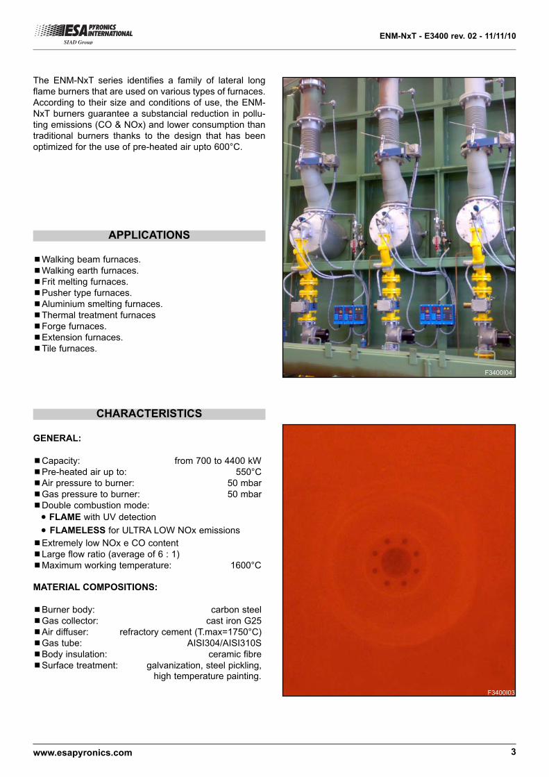
APPLICATIONS
The ENM-NxT series identifies a family of lateral long
flame burners that are used on various types of furnaces.
According to their size and conditions of use, the ENM-
NxT burners guarantee a substancial reduction in pollu-
ting emissions (CO & NOx) and lower consumption than
traditional burners thanks to the design that has been
optimized for the use of pre-heated air upto 600°C.
¾¾Walking beam furnaces.
¾¾Walking earth furnaces.
¾¾Frit melting furnaces.
¾¾Pusher type furnaces.
¾¾Aluminium smelting furnaces.
¾¾Thermal treatment furnaces
¾¾Forge furnaces.
¾¾Extension furnaces.
¾¾Tile furnaces.
CHARACTERISTICS
GENERAL:
¾¾Capacity: from 700 to 4400 kW
¾¾Pre-heated air up to: 550°C
¾¾Air pressure to burner: 50 mbar
¾¾Gas pressure to burner: 50 mbar
¾¾Double combustion mode:
• FLAME with UV detection
• FLAMELESS for ULTRA LOW NOx emissions
¾¾Extremely low NOx e CO content
¾¾Large flow ratio (average of 6 : 1)
¾¾Maximum working temperature: 1600°C
MATERIAL COMPOSITIONS:
¾¾Burner body: carbon steel
¾¾Gas collector: cast iron G25
¾¾Air diffuser: refractory cement (T.max=1750°C)
¾¾Gas tube: AISI304/AISI310S
¾¾Body insulation: ceramic fibre
¾¾Surface treatment: galvanization, steel pickling,high temperature painting.
F3400I03
F3400I04
ENM-NxT - E3400 rev. 02 - 11/11/10
www.esapyronics.com 4
CAPACITY PARAMETERS AND FLAME LENGTH
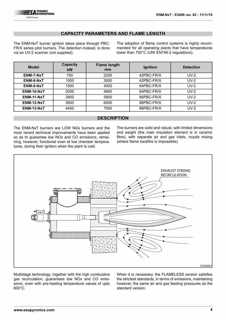
DESCRIPTION
The ENM-NxT burner ignition takes place through PBC-
FR/X series pilot burners. The detection instead, is done
via an UV-2 scanner (not supplied).
The ENM-NxT burners are LOW NOx burners and the
most recent technical improvements have been applied
so as to guarantee low NOx and CO emissions, remai-
ning, however, functional even at low chamber tempera-
tures, during their ignition when the plant is cold.
ModelCapacity
kW
Flame length
mmIgnition Detection
ENM-7-NxT 700 2200 42PBC-FR/X UV-2
ENM-8-NxT 1000 3000 42PBC-FR/X UV-2
ENM-9-NxT 1500 4000 64PBC-FR/X UV-2
ENM-10-NxT 2000 4800 64PBC-FR/X UV-2
ENM-11-NxT 2800 5800 86PBC-FR/X UV-2
ENM-12-NxT 3600 6500 86PBC-FR/X UV-2
ENM-13-NxT 4400 7500 86PBC-FR/X UV-2
The adoption of flame control systems is highly recom-
mended for all operating plants that have temperatures
lower than 750°C (UNI EN746-2 regulations).
EXHAUST STRONGRECIRCULATION
The burners are solid and robust, with limited dimensions
and weight (the main insulation element is in ceramic
fibre), with separate air and gas inlets, nozzle mixing
(where flame backfire is impossible).
Multistage technology, together with the high combustive
gas recirculation, guarantees low NOx and CO emis-
sions, even with pre-heating temperature values of upto
600°C.
When it is necessary, the FLAMELESS version satisfies
the strictest standards, in terms of emissions, maintaining
however, the same air and gas feeding pressures as the
standard version.
D3400I01
ENM-NxT - E3400 rev. 02 - 11/11/10
www.esapyronics.com 5
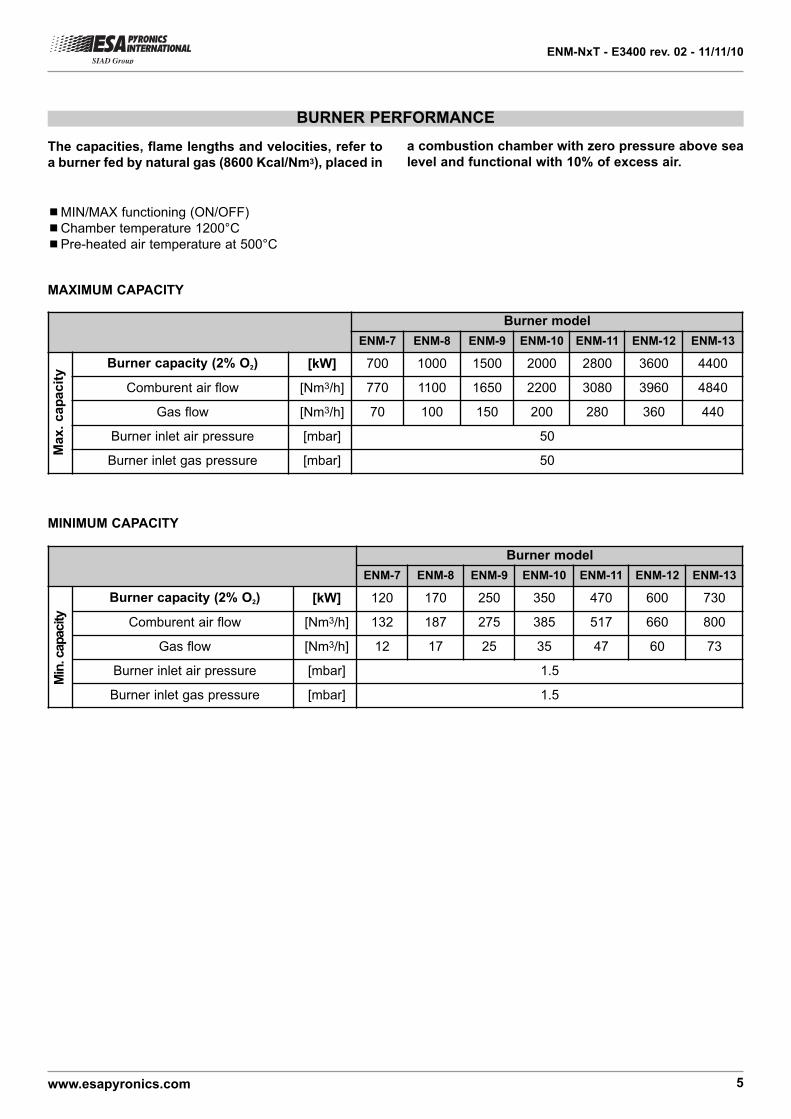
BURNER PERFORMANCE
¾¾MIN/MAX functioning (ON/OFF)
¾¾Chamber temperature 1200°C
¾¾Pre-heated air temperature at 500°C
MAXIMUM CAPACITY
MINIMUM CAPACITY
The capacities, flame lengths and velocities, refer to
a burner fed by natural gas (8600 Kcal/Nm3), placed in
a combustion chamber with zero pressure above sea
level and functional with 10% of excess air.
Burner model
ENM-7 ENM-8 ENM-9 ENM-10 ENM-11 ENM-12 ENM-13
Burner capacity (2% O2) [kW] 700 1000 1500 2000 2800 3600 4400
Comburent air flow [Nm3/h] 770 1100 1650 2200 3080 3960 4840
Gas flow [Nm3/h] 70 100 150 200 280 360 440
Burner inlet air pressure [mbar] 50
Burner inlet gas pressure [mbar] 50
Burner model
ENM-7 ENM-8 ENM-9 ENM-10 ENM-11 ENM-12 ENM-13
Burner capacity (2% O2) [kW] 120 170 250 350 470 600 730
Comburent air flow [Nm3/h] 132 187 275 385 517 660 800
Gas flow [Nm3/h] 12 17 25 35 47 60 73
Burner inlet air pressure [mbar] 1.5
Burner inlet gas pressure [mbar] 1.5
Ma
x.
cap
acit
y
Min
. capacity
ENM-NxT - E3400 rev. 02 - 11/11/10
www.esapyronics.com 6
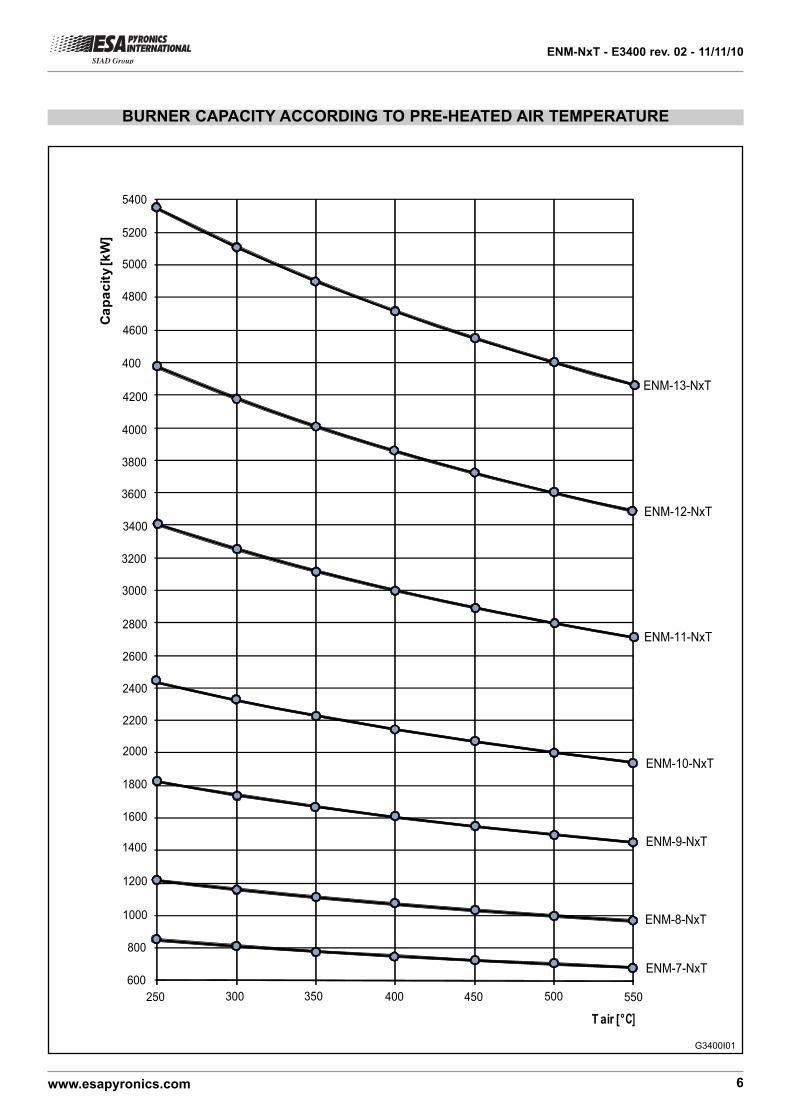
BURNER CAPACITY ACCORDING TO PRE-HEATED AIR TEMPERATURE
T air [°C]
ENM-8-NxT
ENM-7-NxT
ENM-9-NxT
ENM-10-NxT
ENM-11-NxT
ENM-12-NxT
250 300 350 400 450 500 550
Cap
acity
[kW
]
4200
4000
3800
3600
3400
3200
3000
2800
2600
2400
2200
2000
1800
1600
1400
1200
1000
800
600
5000
4800
5200
5400
4600
ENM-13-NxT
400
G3400I01
ENM-NxT - E3400 rev. 02 - 11/11/10
www.esapyronics.com 7
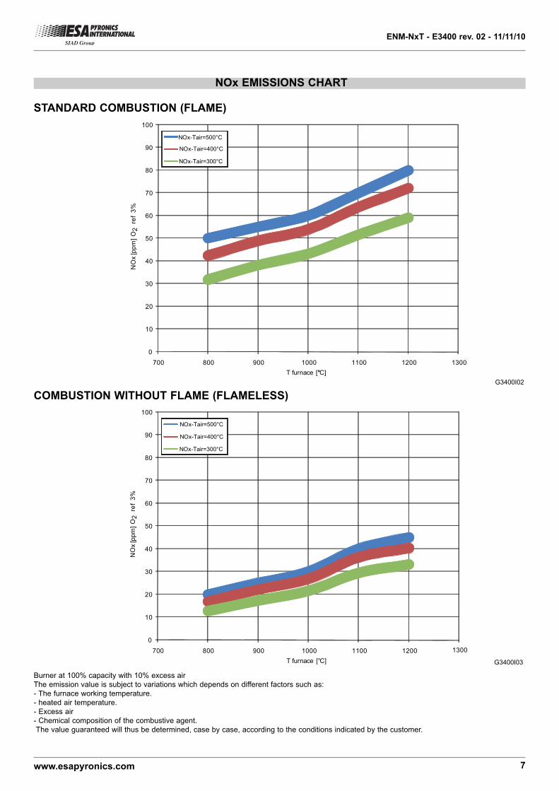
NOx EMISSIONS CHART
0
10
20
30
40
50
60
70
80
90
100
700 800 900 1000 1100 1200 1300
NO
x [p
pm] O
2 re
f 3%
T furnace [°C]
NOx-Tair=500°C
NOx-Tair=400°C
NOx-Tair=300°C
0
10
20
30
40
50
60
70
80
90
100
700 800 900 1000 1100 1200 1300
NO
x [p
pm] O
2 re
f 3%
T furnace [°C]
NOx-Tair=500°C
NOx-Tair=400°C
NOx-Tair=300°C
G3400I02
G3400I03
STANDARD COMBUSTION (FLAME)
COMBUSTION WITHOUT FLAME (FLAMELESS)
Burner at 100% capacity with 10% excess air
The emission value is subject to variations which depends on different factors such as:
- The furnace working temperature.
- heated air temperature.
- Excess air
- Chemical composition of the combustive agent.
The value guaranteed will thus be determined, case by case, according to the conditions indicated by the customer.
ENM
-7-N
xT
ENM
-8-N
xT
ENM
-9-N
xT
ENM
-10-
NxT
ENM
-11-
NxT
ENM
-12-
NxT
1
10
100
10 100 10000
ENM
-13-
NxT
ENM-NxT - E3400 rev. 02 - 11/11/10
www.esapyronics.com 8
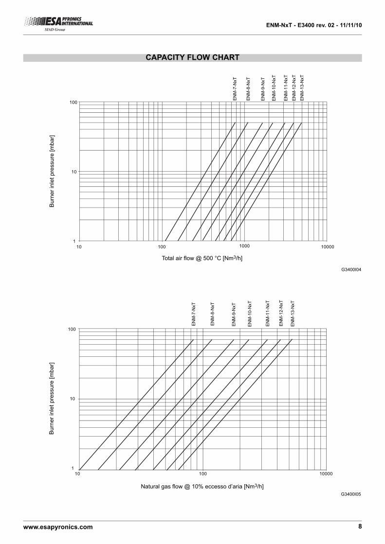
G3400I05
Natural gas flow @ 10% eccesso d’aria [Nm3/h]
Burn
er
inle
t pre
ssure
[m
bar]
CAPACITY FLOW CHART
ENM
-7-N
xT
10001
10
100
10 100 10000EN
M-8
-NxT
ENM
-9-N
xT
ENM
-10-
NxT
ENM
-11-
NxT
ENM
-12-
NxT
ENM
-13-
NxT
G3400I04
Total air flow @ 500 °C [Nm3/h]
Bu
rne
r in
let
pre
ssu
re [
mb
ar]
ENM-NxT - E3400 rev. 02 - 11/11/10
www.esapyronics.com 9
//
//
AIR INLET
GAS INLET
GAS LINE FOR PILOT BURNERS
AIR LINE FOR PILOT BURNERS
01
////
+
////
-
02
0405 08
03
09
10
11
13
1218
06
1715
14
16
07
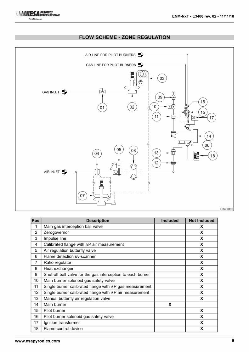
FLOW SCHEME - ZONE REGULATION
Pos. Description Included Not Included
1 Main gas interception ball valve X
2 Zerogovernor X
3 Impulse line X
4 Calibrated flange with ΔΔP air measurement X
5 Air regulation butterfly valve X
6 Flame detection uv-scanner X
7 Ratio regulator X
8 Heat exchanger X
9 Shut-off ball valve for the gas interception to each burner X
10 Main burner solenoid gas safety valve X
11 Single burner calibrated flange with ΔΔP gas measurement X
12 Single burner calibrated flange with ΔΔP air measurement X
13 Manual butterfly air regulation valve X
14 Main burner X
15 Pilot burner X
16 Pilot burner solenoid gas safety valve X
17 Ignition transformer X
18 Flame control device X
D3400I02
ENM-NxT - E3400 rev. 02 - 11/11/10
www.esapyronics.com 10
//
GAS LINE FOR PILOT BURNERS
AIR LINE FOR PILOT BURNERS
01
10
1118
17
1514
16
13
02 04
05
AIR INLET
07
06esa pt II Patented - Brev. I 1268539 esa pt II Patented - Brev. I 1268539
TC
GAS INLET
03
08 09
12
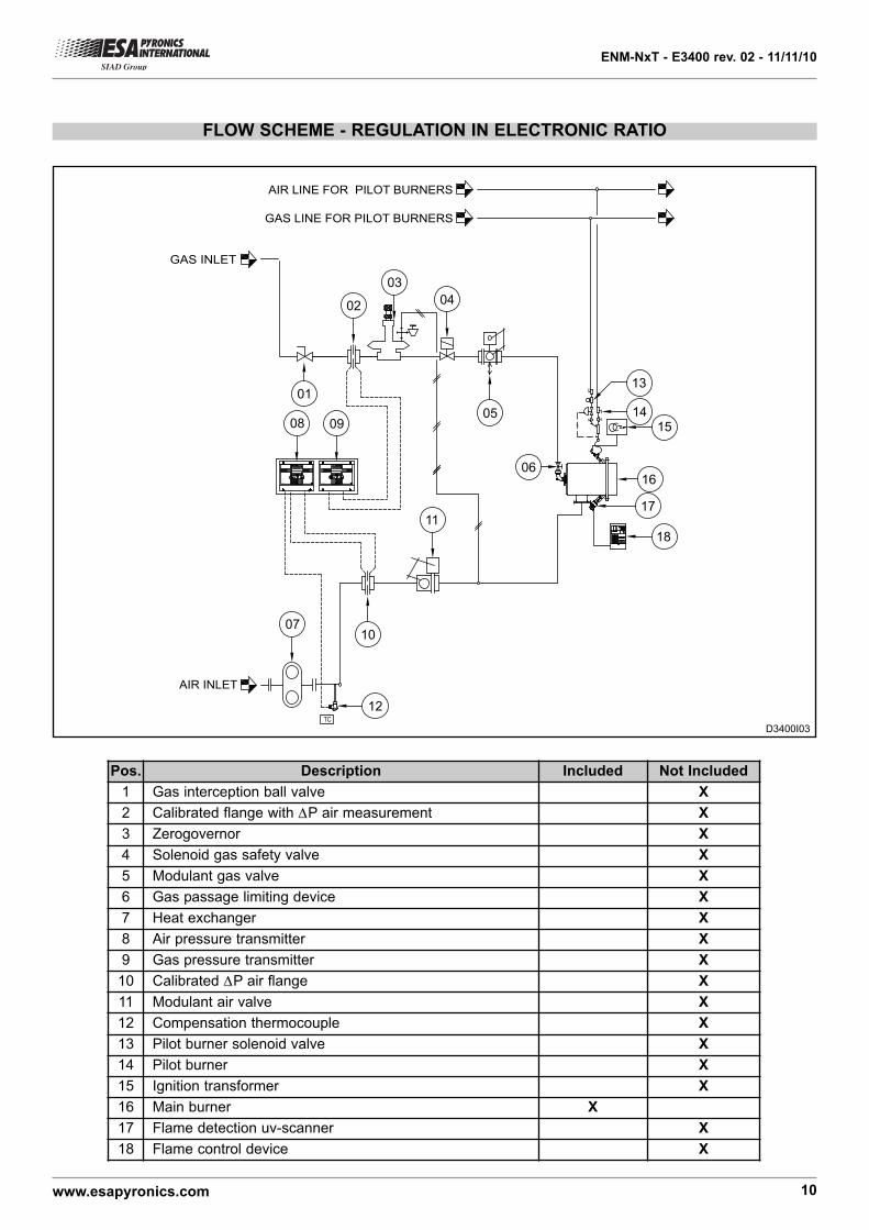
FLOW SCHEME - REGULATION IN ELECTRONIC RATIO
Pos. Description Included Not Included
1 Gas interception ball valve X
2 Calibrated flange with ΔΔP air measurement X
3 Zerogovernor X
4 Solenoid gas safety valve X
5 Modulant gas valve X
6 Gas passage limiting device X
7 Heat exchanger X
8 Air pressure transmitter X
9 Gas pressure transmitter X
10 Calibrated ΔΔP air flange X
11 Modulant air valve X
12 Compensation thermocouple X
13 Pilot burner solenoid valve X
14 Pilot burner X
15 Ignition transformer X
16 Main burner X
17 Flame detection uv-scanner X
18 Flame control device X
D3400I03
ENM-NxT - E3400 rev. 02 - 11/11/10
www.esapyronics.com 11
WARNINGS
¾¾ The ENM-NxT series burners are to be used in fixedinstallations. If mobile installations should be necessary
(bell furnaces, etc ...), take into consideration that possi-
ble damages could be caused due to the movement of
the actual furnace.
¾¾ Burner ignition must always be carried out at mini-mum power, to then modulate towards the maximum,
thus facilitating ignitions and reducing outlet overpressu-
res.
¾¾ The passing from the minimum to the maximumpower, and vice-versa, must be gradual and not imme-
diate.
¾¾ For all applications at low temperatures (upto 750°C),the burner ignition as well as the combustive gas sole-
noid valve command must be carried out using a certi-
fied burner control device.
¾¾ The use of flexible joints is always necessary in thepresence of pre-heated air.
¾¾ To avoid possible damage to the burners, make surethat the blower does not blow air which is fouled by com-
bustion products, oils solvents or other. To avoid these
phenomena from taking place, preferably install the blo-
wer or the suction duct outside the establishment and far
from exhaust pipes.
¾¾ Check the correct connection of the feeding lines afterinstallation. Before switching the burner on, check that
the comburent air pressure and combustive gas pressu-
re values are correct.
¾¾ The burner can only function within the indicatedpower range. Functioning with excessive power could
compromise burner perfomance and life span. In that
case the ESA PYRONICS general warranty conditions
will automatically expire and ESA PYRONICS will not be
held responsible for any damage caused to persons or
objects.
¾¾ In case there are problems with the other devicesduring the burner start-up phase, for the connection of
high tension cable to the ignition electrode, use the con-
nector with an antidisturbance filter.
¾¾ Avoid burner ignition close to each other so as not toheat the ignition command system devices (solenoid val-
ves and transformers). Prewash time lapse + first safety
time lapse + min. of 5 sec. = time lapse between one igni-
tion and another. (however, do not attempt more than 2
ignitions during a 30sec. time lapse).
¾¾ Make sure the power supply is TURNED OFF whenintervening on the burner and its devices. In case of bur-
ner malfunctioning, follow the indications in the
‘Maintenance’ chapter of the present manual or contact
ESA-PYRONICS assistance.
¾¾ Any modification or repair done by third parties cancompromise the application safety and automatically
cause the general warranty conditions to expire.
ENM-NxT - E3400 rev. 02 - 11/11/10
www.esapyronics.com 12
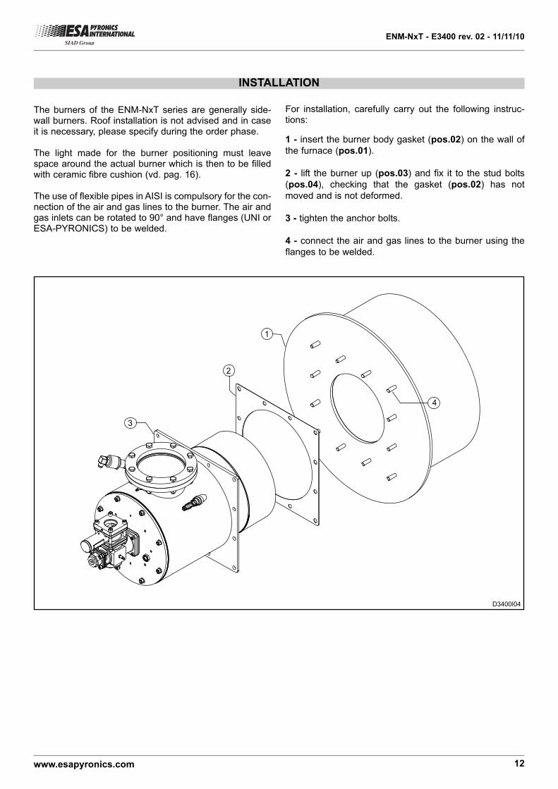
INSTALLATION
The burners of the ENM-NxT series are generally side-wall burners. Roof installation is not advised and in caseit is necessary, please specify during the order phase.
The light made for the burner positioning must leavespace around the actual burner which is then to be filledwith ceramic fibre cushion (vd. pag. 16).
The use of flexible pipes in AISI is compulsory for the con-nection of the air and gas lines to the burner. The air andgas inlets can be rotated to 90° and have flanges (UNI orESA-PYRONICS) to be welded.
1
2
3
4
D3400I04
For installation, carefully carry out the following instruc-tions:
1 - insert the burner body gasket (pos.02) on the wall of
the furnace (pos.01).
2 - lift the burner up (pos.03) and fix it to the stud bolts
(pos.04), checking that the gasket (pos.02) has not
moved and is not deformed.
3 - tighten the anchor bolts.
4 - connect the air and gas lines to the burner using the
flanges to be welded.
ENM-NxT - E3400 rev. 02 - 11/11/10
www.esapyronics.com 13
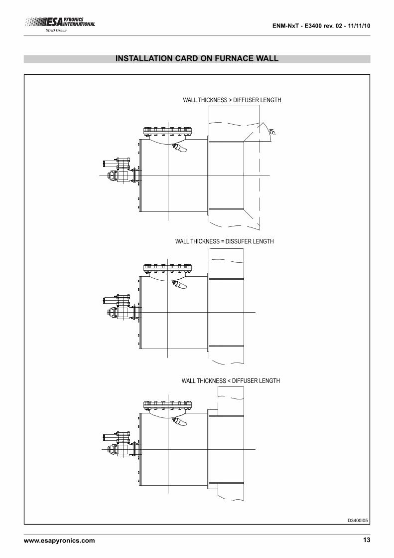
INSTALLATION CARD ON FURNACE WALL
WALL THICKNESS > DIFFUSER LENGTH
WALL THICKNESS = DISSUFER LENGTH
WALL THICKNESS < DIFFUSER LENGTH
45°
D3400I05
ENM-NxT - E3400 rev. 02 - 11/11/10
www.esapyronics.com 14
START-UP - SETTING
The procedures indicated in the following chapter must be
carried out by expert technicians. The non-observance of
the instructions given can provoke dangerous conditions.
1 - Check that the combustion air pressure exiting the blo-
wer and the combustive fuel pressure are both within the
allowed range.
2 - Adjust the working pressure and the safety device
pressure of the combustion plant, whether there is one
per burner or one for the whole plant i.e. gas pressure
reduction gear, block valve, relief valve, pressure swit-
ches etc. Simulate the intervention of all the safety devi-
ces including the intervention of the safety over tempera-
ture, checking that the fuel safety block devices react pro-
perly.
3 - Place the air regulation valve in the maximum opening
position and adjust the burner inlet pressure referring to
the values indicated in the ‘Burner Performances’ chapter.
4 - Place the air regulation valve in the minimum opening
position and adjust its opening to obtain (in burner inlet
and ejector) the relative minimum power pressure.
5 - Activate the burner control device and attempt the pilot
burner (*) ignition until it switches on. While attempting to
ignite the burner, act on the gas adjustment valve and,
starting from the totally closed position, open it gradually
until the main burner ignites.
6 - Fully open the air regulation valve and adjust, via the
gas adjustment valve, the maximum fuel capacity, chec-
king the differential pressure created on the calibrated
gas flange.
7 - Double check that, at minimum and maximum power,
the burner inlet pressures correspond to the values in the
in the ‘Burner Performances’ chapter. These values may
differ depending on whether the burner is on or off.
8 - If necessary, with both burners running at the same
power, analyse the combustion products in the chamber
(where possible).
9 - Repeatedly attempt ignition at minimum burner power,
with maximum amplitude, to check the ignition reliability
and flame stability during the adjustment.
(*) For pilot burner ignition and setting, please refer to n.
E3280 technical data sheet.
ENM-NxT - E3400 rev. 02 - 11/11/10
www.esapyronics.com 15
GENERAL MAINTENANCE PLAN
NOTES:
Key: O = ordinary / E = extraordinary
(*) it is suggested that the gaskets on the gas side be replaced after every dismantling of the gas feeding line and that
high temperature gaskets be used.
Operation Type Advised time Notes
Pilot burner high tension electrode
connectorO annual
check the integrity of the outer plastic
and oxidization of the internal connector
and of the electrode terminal
Pilot burner ignition electrode O annual replace if the kantal termial is worn
Air diffuser integrity E annual
at every maintenance check with furna-
ce turned off, from the inside, make sure
there are no cracks in the refractory
material. Any cracks must be filled with
special refractory material or liquid fibre.
Cleaning of uv-scanner watch glass O every semesterreduce to quaterly check in dusty envi-
ronments
Uv-scanner replacement O10.000 h.
of functioningin any case, every two years
Gas side gasket replacement (*) O every two years see note
Burner settings O annualrepeat all the steps in the
“START-UP AND SETTINGS" chapter
Oil lance check O annualcheck that the compressed air and oil
holes are not occluded
ENM-NxT - E3400 rev. 02 - 11/11/10
www.esapyronics.com 16
D3400I06
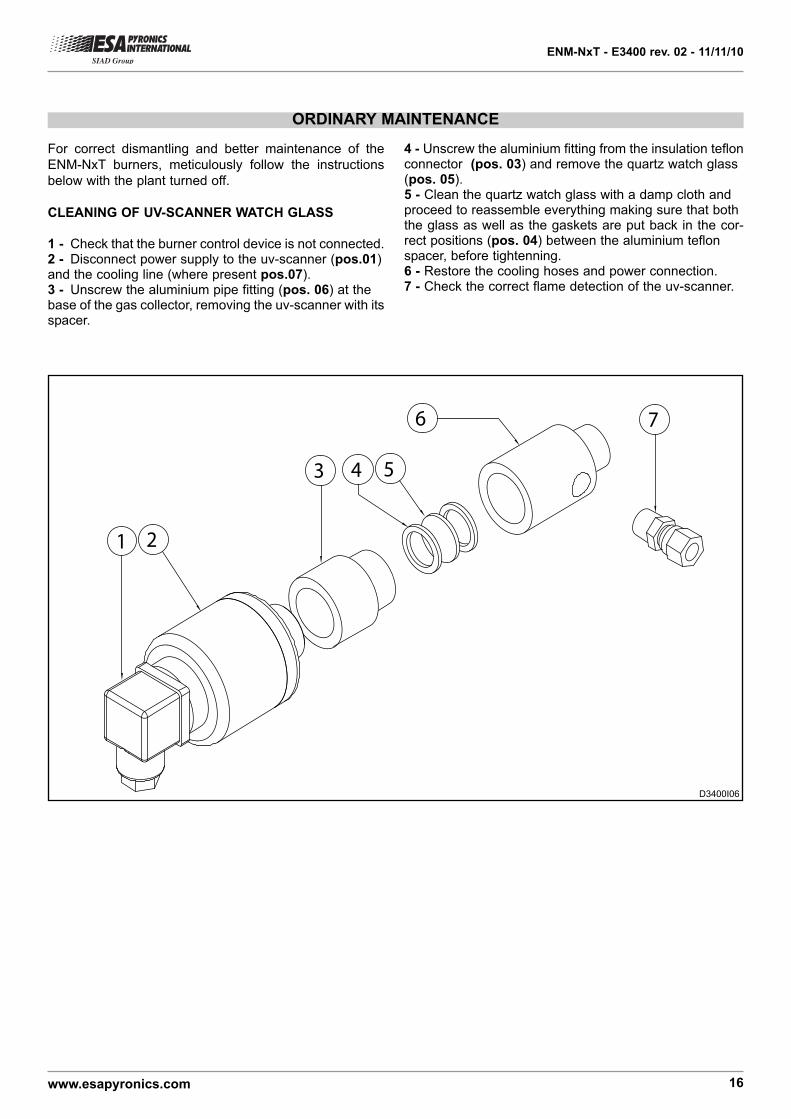
ORDINARY MAINTENANCE
For correct dismantling and better maintenance of the
ENM-NxT burners, meticulously follow the instructions
below with the plant turned off.
CLEANING OF UV-SCANNER WATCH GLASS
1 - Check that the burner control device is not connected.2 - Disconnect power supply to the uv-scanner (pos.01)and the cooling line (where present pos.07).3 - Unscrew the aluminium pipe fitting (pos. 06) at thebase of the gas collector, removing the uv-scanner with itsspacer.
1 2
3 4 5
6 7
4 - Unscrew the aluminium fitting from the insulation teflonconnector (pos. 03) and remove the quartz watch glass(pos. 05).5 - Clean the quartz watch glass with a damp cloth andproceed to reassemble everything making sure that boththe glass as well as the gaskets are put back in the cor-rect positions (pos. 04) between the aluminium teflonspacer, before tightenning.6 - Restore the cooling hoses and power connection.7 - Check the correct flame detection of the uv-scanner.
ENM-NxT - E3400 rev. 02 - 11/11/10
www.esapyronics.com 17
For correct dismantling and better maintenance of the
ENM-NxT burners, meticulously follow the instructions
below with the plant turned off.
BURNER IN LOCKOUT
In burner lockout conditions refer to the indications
of the burner control device as well as the relative
manual to identify the cause. After this, the main
cases have been indicated below:
¾¾Illegal flame detection: lockout due to illegal flame
signal detection during the phases that precede the igni-
tion or following the switching off. The causes could be
due to the detection system (broken sensor or presence
of humidity), or else in the gas drawn by the safety sole-
noid valve which allows the burner to remain on.
¾¾Ignition failure: lockout due to missing flame forma-
tion during start-up. The causes could be due to the igni-
stion system (missing spark, broken electrodes or elec-
trodes not in correct position), in bad regulation of the
flow fuel or combustive agents or in the detection system
(broken sensor or interrupted cables). Specifically, in the
first two cases the flame does not trigger off, whilst in the
last case, the flame forms but the burner control device
is unable to detect it.
¾¾Flame signal loss: lockout due to flame signal loss
during the normal functioning of the burner. The causes
may be found in the regulation of the fuel flow or combu-
stive agents (rapid flow variations, regulation out of allo-
wed range) or in the detection system (broken, dirty or
badly positioned sensors).
UV-SCANNER REPLACEMENT
1 - Check that the burner control device is not connected.2 - Disconnect the electrical flow to the uv-scanner (pos.01) and to the cooling line (where present).3 - Unscrew the aluminium pipe fitting at the base of thegas collector (pos. 02), removing the uv-scanner with itsspacer.4 - Screw the new component back on, in the same posi-tion, after having checked the correct position of thewatch glass insulation between the aluminium and teflonspacers.5 - Restore the cooling pipes and the electrical connec-tion.6 - Check the correct uv-scanner flame detection.
AIR DIFFUSER REPLACEMENT
1 - Disconnect all the air and gas lines to the burner.2 - Dismantle the burner from the furnace wall and placeit with the diffuser facing upwards, fixing it onto a special
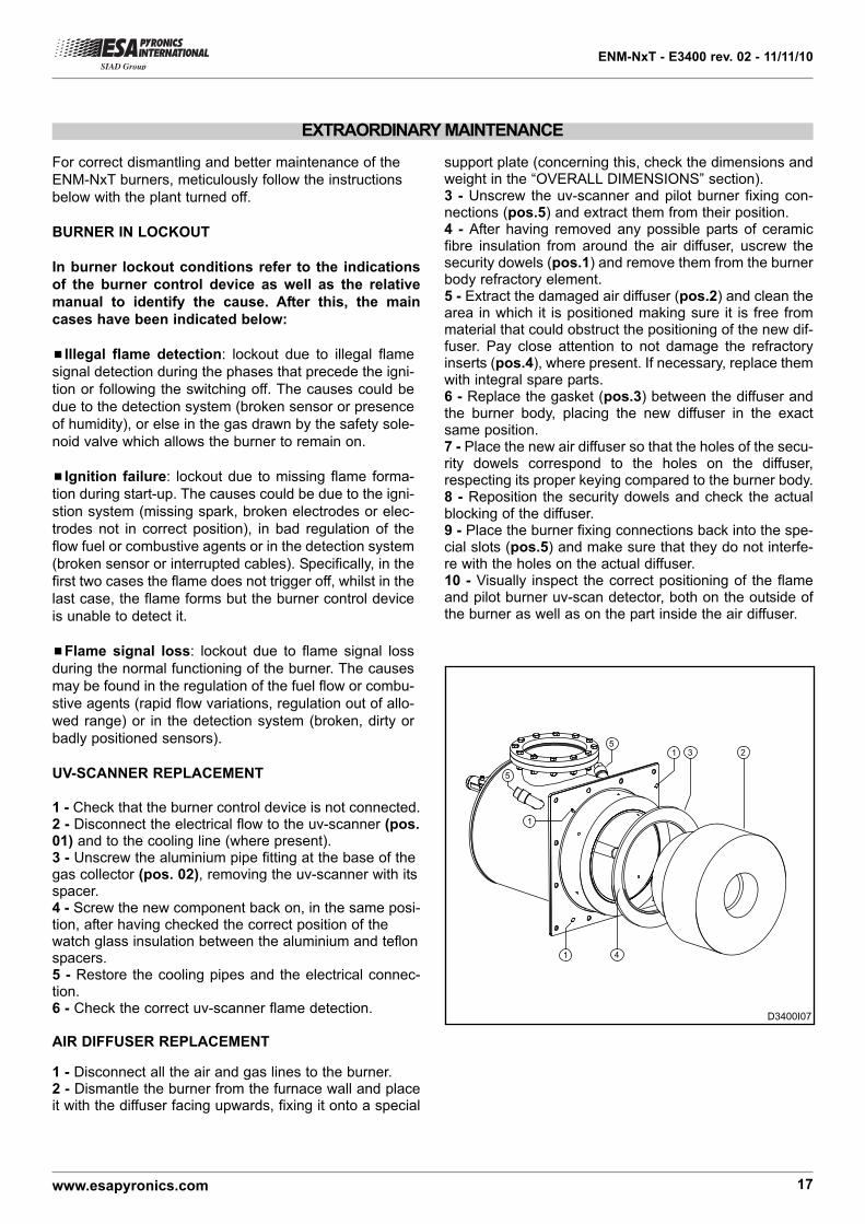
EXTRAORDINARY MAINTENANCE
support plate (concerning this, check the dimensions andweight in the “OVERALL DIMENSIONS” section).3 - Unscrew the uv-scanner and pilot burner fixing con-nections (pos.5) and extract them from their position. 4 - After having removed any possible parts of ceramicfibre insulation from around the air diffuser, uscrew thesecurity dowels (pos.1) and remove them from the burnerbody refractory element. 5 - Extract the damaged air diffuser (pos.2) and clean thearea in which it is positioned making sure it is free frommaterial that could obstruct the positioning of the new dif-fuser. Pay close attention to not damage the refractoryinserts (pos.4), where present. If necessary, replace themwith integral spare parts.6 - Replace the gasket (pos.3) between the diffuser andthe burner body, placing the new diffuser in the exactsame position.7 - Place the new air diffuser so that the holes of the secu-rity dowels correspond to the holes on the diffuser,respecting its proper keying compared to the burner body. 8 - Reposition the security dowels and check the actualblocking of the diffuser. 9 - Place the burner fixing connections back into the spe-cial slots (pos.5) and make sure that they do not interfe-re with the holes on the actual diffuser.10 - Visually inspect the correct positioning of the flameand pilot burner uv-scan detector, both on the outside ofthe burner as well as on the part inside the air diffuser.
1 3 2
1
1
4
5
5
D3400I07
ENM-NxT - E3400 rev. 02 - 11/11/10
www.esapyronics.com 18
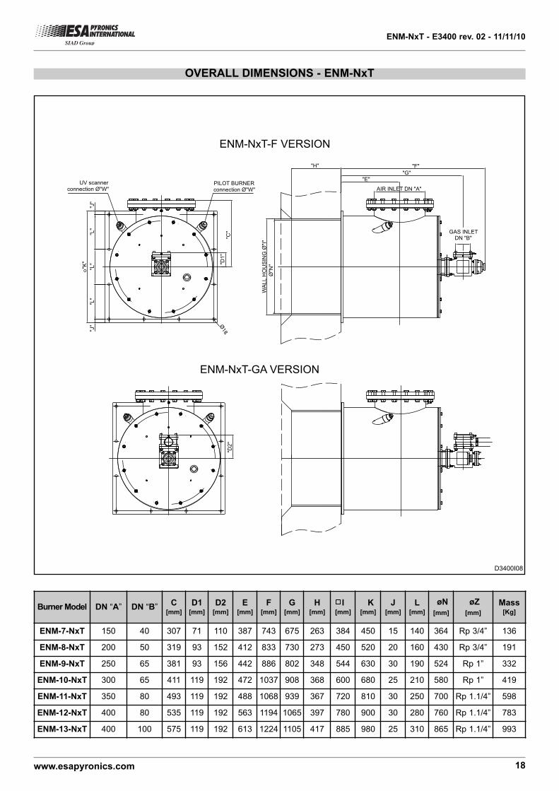
OVERALL DIMENSIONS - ENM-NxT
"E""G"
"F""H"
GAS INLETDN "B"
AIR INLET DN "A"
Ø"N
""D1"
"C"
"J"
"L"
"L"
"L"
"J"
o"K
"
UV scannerconnection Ø"W"
PILOT BURNERconnection Ø"W"
WAL
L H
OU
SIN
G Ø
"I"
"D2"
ENM-NxT-F VERSION
ENM-NxT-GA VERSION
Ø18
D3400I08
Burner Model DN “A” DN “B”C
[mm]
D1[mm]
D2[mm]
E[mm]
F[mm]
G[mm]
H[mm]
I[mm]
K[mm]
J[mm]
L[mm]
øN
[mm]
øZ
[mm]
Mass[Kg]
ENM-7-NxT 150 40 307 71 110 387 743 675 263 384 450 15 140 364 Rp 3/4” 136
ENM-8-NxT 200 50 319 93 152 412 833 730 273 450 520 20 160 430 Rp 3/4” 191
ENM-9-NxT 250 65 381 93 156 442 886 802 348 544 630 30 190 524 Rp 1” 332
ENM-10-NxT 300 65 411 119 192 472 1037 908 368 600 680 25 210 580 Rp 1” 419
ENM-11-NxT 350 80 493 119 192 488 1068 939 367 720 810 30 250 700 Rp 1.1/4” 598
ENM-12-NxT 400 80 535 119 192 563 1194 1065 397 780 900 30 280 760 Rp 1.1/4” 783
ENM-13-NxT 400 100 575 119 192 613 1224 1105 417 885 980 25 310 865 Rp 1.1/4” 993
ENM-NxT - E3400 rev. 02 - 11/11/10
www.esapyronics.com 19
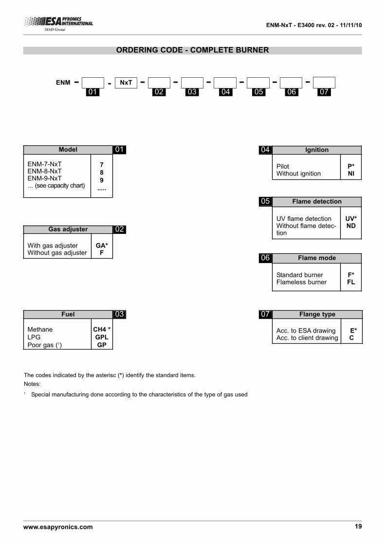
ORDERING CODE - COMPLETE BURNER
NxT - ---ENM - -- -
The codes indicated by the asterisc (*) identify the standard items.
Notes:
1 Special manufacturing done according to the characteristics of the type of gas used
Model
ENM-7-NxTENM-8-NxTENM-9-NxT... (see capacity chart)
7
8
9
.....
Fuel
Methane
LPG
Poor gas (1)
CH4 *
GPL
GP
Gas adjuster
With gas adjusterWithout gas adjuster
GA*F
Ignition
PilotWithout ignition
P* NI
Flange type
Acc. to ESA drawingAcc. to client drawing
E*C
Flame detection
UV flame detectionWithout flame detec-tion
UV*ND
01
01 02 03 04 05 06
02
03 07
04
05
Flame mode
Standard burnerFlameless burner
F*FL
06
07