Embed Size (px)
Citation preview
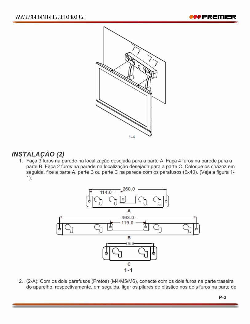
1-4
1-1
A
B
B
1-2
75.0 75.0
10.5
1-3
32 TV-5407LED
14
P-1 P-2
1-4
1-1
A
B
B
1-2
75.0 75.0
10.5
1-3
32 TV-5407LED
14
P-1 P-2
1-4
1-1
A
B
B
1-2
75.0 75.0
10.5
1-3
32 TV-5407LED
14
P-1 P-2
1-3
1-1 1-3
1-2
1-1
2-B2-A
SAEG00-S827
metal
260.0114.0
463.0119.0
A
B
C
P-3 P-4 P-5
A
A
A
A
A
B
C
1-3
1-1 1-3
1-2
1-1
2-B2-A
SAEG00-S827
metal
260.0114.0
463.0119.0
A
B
C
P-3 P-4 P-5
A
A
A
A
A
B
C
1-3
1-1 1-3
1-2
1-1
2-B2-A
SAEG00-S827
metal
260.0114.0
463.0119.0
A
B
C
P-3 P-4 P-5
A
A
A
A
A
B
C
MANUAL DO USUÁRIO MONTAGEM DE TV LED (32”)
TV-5407LED
PREZADO CLIENTE A fim de obter o melhor desempenho de seu produto, por favor, leia este manual do usuário cuidadosamente antes de começar a usá-lo, e mantê-lo para referência futura. Se você precisar de suporte adicional, por favor, escreva para: [email protected]

P-1
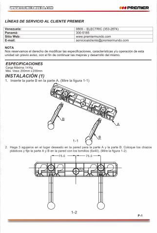
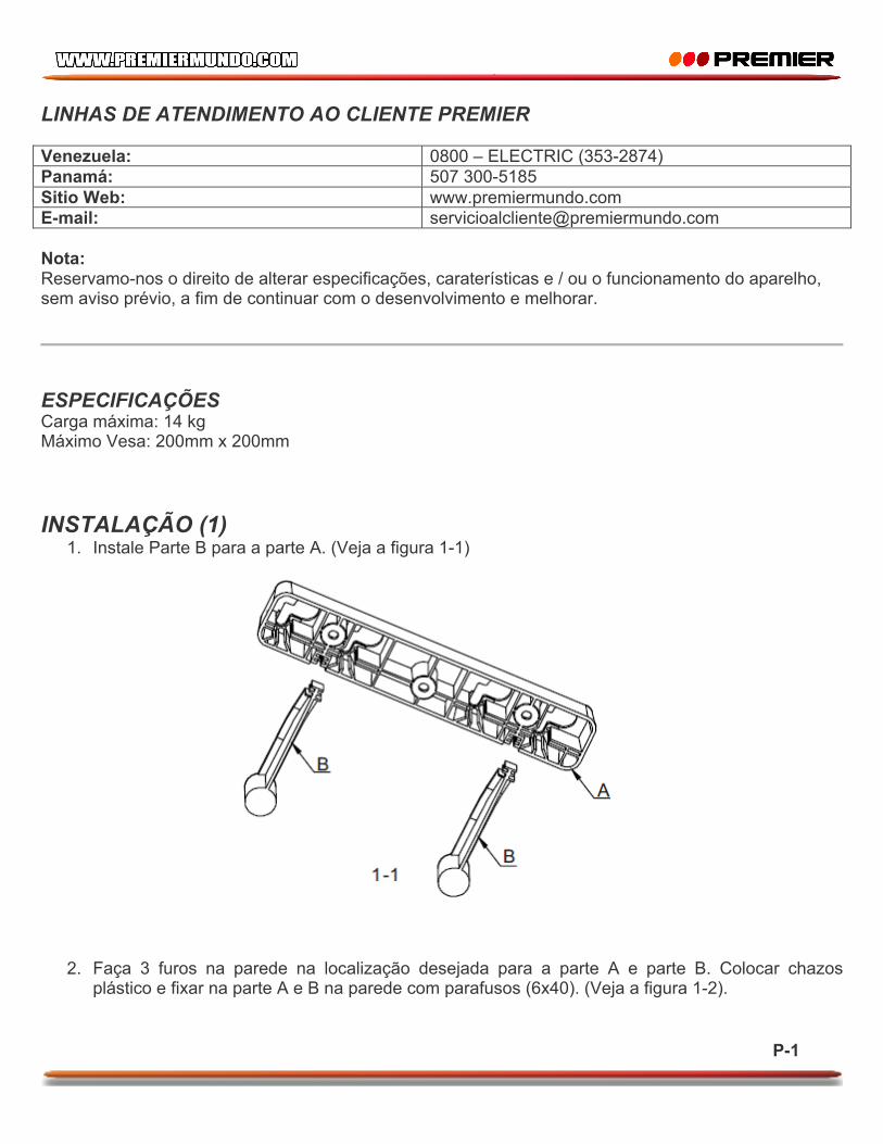
LINHAS DE ATENDIMENTO AO CLIENTE PREMIER Venezuela: 0800 – ELECTRIC (353-2874) Panamá: 507 300-5185 Sitio Web: www.premiermundo.com E-mail: [email protected] Nota: Reservamo-nos o direito de alterar especificações, caraterísticas e / ou o funcionamento do aparelho, sem aviso prévio, a fim de continuar com o desenvolvimento e melhorar.
ESPECIFICAÇÕES Carga máxima: 14 kg Máximo Vesa: 200mm x 200mm INSTALAÇÃO (1)
1. Instale Parte B para a parte A. (Veja a figura 1-1)
2. Faça 3 furos na parede na localização desejada para a parte A e parte B. Colocar chazos plástico e fixar na parte A e B na parede com parafusos (6x40). (Veja a figura 1-2).
P-2
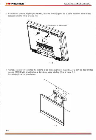
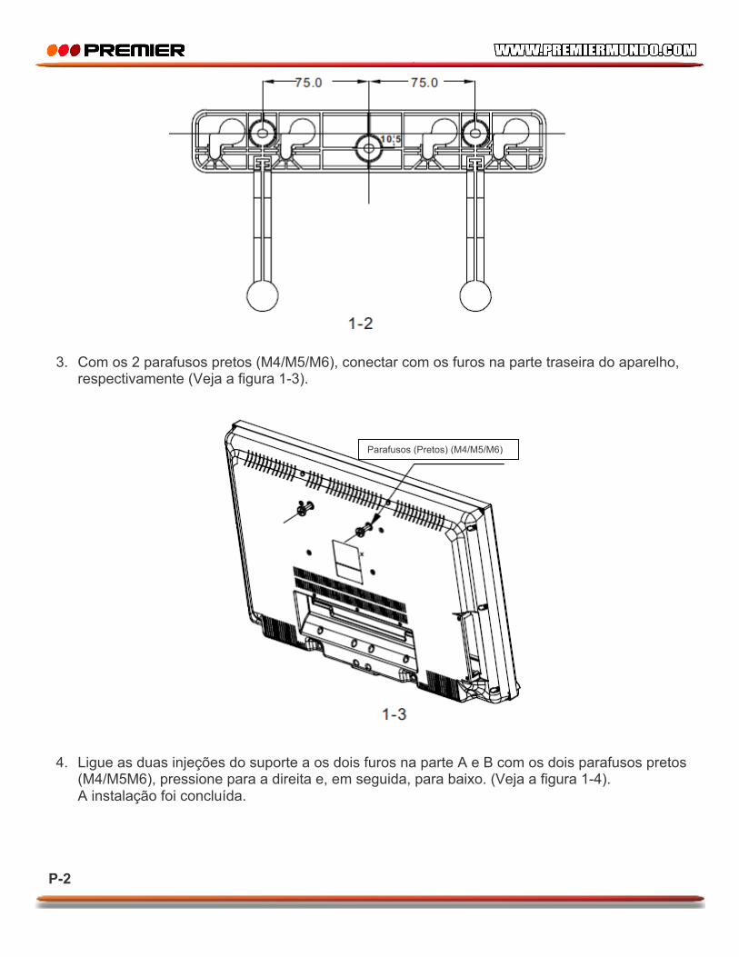
3. Com os 2 parafusos pretos (M4/M5/M6), conectar com os furos na parte traseira do aparelho, respectivamente (Veja a figura 1-3).
4. Ligue as duas injeções do suporte a os dois furos na parte A e B com os dois parafusos pretos (M4/M5M6), pressione para a direita e, em seguida, para baixo. (Veja a figura 1-4). A instalação foi concluída.
Parafusos (Pretos) (M4/M5/M6)

P-3
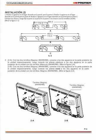
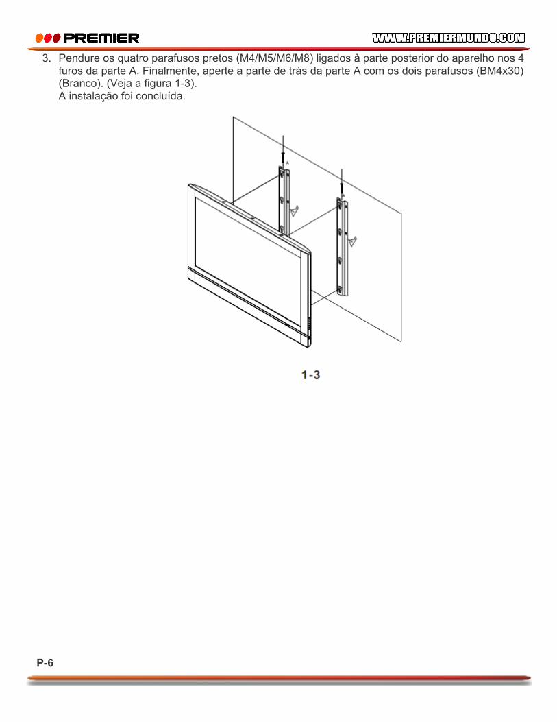
INSTALAÇÃO (2) 1. Faça 3 furos na parede na localização desejada para a parte A. Faça 4 furos na parede para a
parte B. Faça 2 furos na parede na localização desejada para a parte C. Coloque os chazoz em seguida, fixe a parte A, parte B ou parte C na parede com os parafusos (6x40). (Veja a figura 1-1).
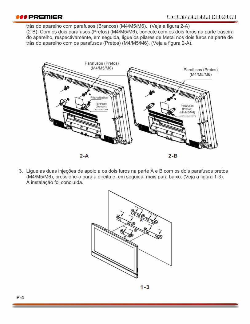
2. (2-A): Com os dois parafusos (Pretos) (M4/M5/M6), conecte com os dois furos na parte traseira do aparelho, respectivamente, em seguida, ligar os pilares de plástico nos dois furos na parte de
P-4
trás do aparelho com parafusos (Brancos) (M4/M5/M6). (Veja a figura 2-A) (2-B): Com os dois parafusos (Pretos) (M4/M5/M6), conecte com os dois furos na parte traseira do aparelho, respectivamente, em seguida, ligue os pilares de Metal nos dois furos na parte de trás do aparelho com os parafusos (Pretos) (M4/M5/M6). (Veja a figura 2-A).
3. Ligue as duas injeções de apoio a os dois furos na parte A e B com os dois parafusos pretos
(M4/M5/M6), pressione-o para a direita e, em seguida, mais para baixo. (Veja a figura 1-3). A instalação foi concluída.
Parafusos (Pretos) (M4/M5/M6) Parafusos (Pretos)
(M4/M5/M6)
Parafusos (Brancos)
(M4/M5/M6) Parafusos (Pretos)
(M4/M5/M6)
P-5
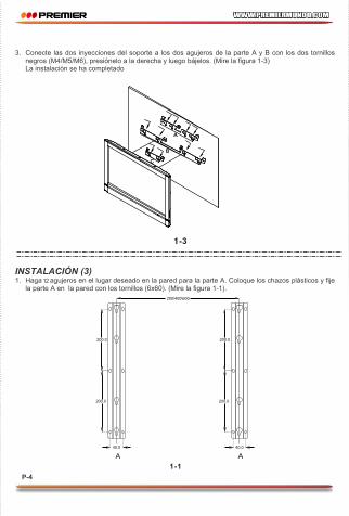
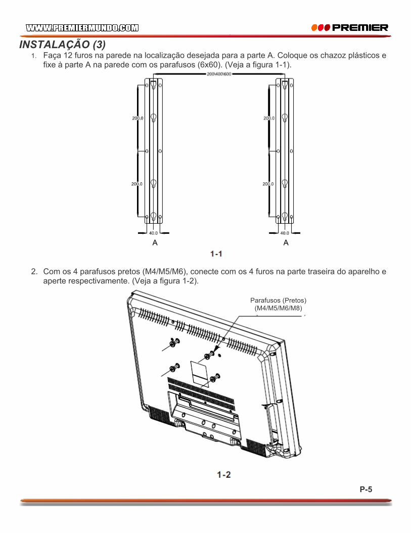
INSTALAÇÃO (3) 1. Faça 12 furos na parede na localização desejada para a parte A. Coloque os chazoz plásticos e
fixe à parte A na parede com os parafusos (6x60). (Veja a figura 1-1).
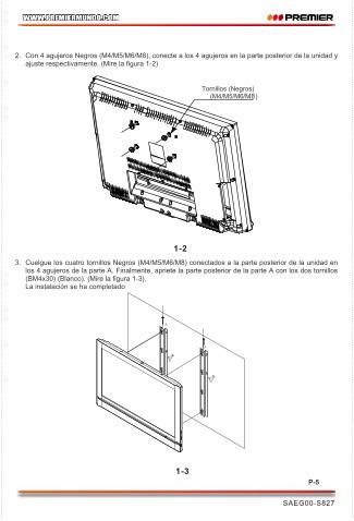
2. Com os 4 parafusos pretos (M4/M5/M6), conecte com os 4 furos na parte traseira do aparelho e aperte respectivamente. (Veja a figura 1-2).
Parafusos (Pretos) (M4/M5/M6/M8)

P-6
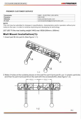
3. Pendure os quatro parafusos pretos (M4/M5/M6/M8) ligados à parte posterior do aparelho nos 4 furos da parte A. Finalmente, aperte a parte de trás da parte A com os dois parafusos (BM4x30) (Branco). (Veja a figura 1-3). A instalação foi concluída.
1-4
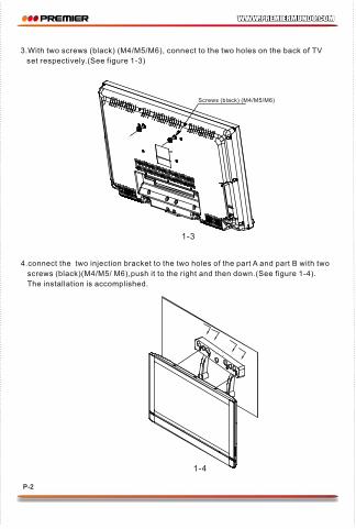
3.With two screws (black) (M4/M5/M6), connect to the two holes on the back of TV
set respectively.(See figure 1-3)
4.connect the two injection bracket to the two holes of the part A and part B with two
screws (black)(M4/M5/ M6),push it to the right and then down.(See figure 1-4).
The installation is accomplished.
1-1
A
B
B
1-2
75.0 75.0
10.5
1.Insert part B into part A.(See figure 1-1)
2.Make 3 holes at the suitable places on the wall for part A and part B, put in plastic particles and then fix part A and part B on the wall with the screws(6x40).(See figure 1-2)
Wall Mount Installation(1):
1-3
Screws (black) (M4/M5/M6)
(32 LED TV:the max loading weight:14KG,max VESA:200mm x 200mm)LED TV 32 TV-5407LED
P-1 P-2

MANUAL DO USUÁRIO MONTAGEM DE TV LED (32”)
TV-5407LED
PREZADO CLIENTE A fim de obter o melhor desempenho de seu produto, por favor, leia este manual do usuário cuidadosamente antes de começar a usá-lo, e mantê-lo para referência futura. Se você precisar de suporte adicional, por favor, escreva para: [email protected]
P-1
LINHAS DE ATENDIMENTO AO CLIENTE PREMIER Venezuela: 0800 – ELECTRIC (353-2874) Panamá: 507 300-5185 Sitio Web: www.premiermundo.com E-mail: [email protected] Nota: Reservamo-nos o direito de alterar especificações, caraterísticas e / ou o funcionamento do aparelho, sem aviso prévio, a fim de continuar com o desenvolvimento e melhorar.
ESPECIFICAÇÕES Carga máxima: 14 kg Máximo Vesa: 200mm x 200mm INSTALAÇÃO (1)
1. Instale Parte B para a parte A. (Veja a figura 1-1)
2. Faça 3 furos na parede na localização desejada para a parte A e parte B. Colocar chazos plástico e fixar na parte A e B na parede com parafusos (6x40). (Veja a figura 1-2).

P-2
3. Com os 2 parafusos pretos (M4/M5/M6), conectar com os furos na parte traseira do aparelho, respectivamente (Veja a figura 1-3).
4. Ligue as duas injeções do suporte a os dois furos na parte A e B com os dois parafusos pretos (M4/M5M6), pressione para a direita e, em seguida, para baixo. (Veja a figura 1-4). A instalação foi concluída.
Parafusos (Pretos) (M4/M5/M6)
P-3
INSTALAÇÃO (2) 1. Faça 3 furos na parede na localização desejada para a parte A. Faça 4 furos na parede para a
parte B. Faça 2 furos na parede na localização desejada para a parte C. Coloque os chazoz em seguida, fixe a parte A, parte B ou parte C na parede com os parafusos (6x40). (Veja a figura 1-1).
2. (2-A): Com os dois parafusos (Pretos) (M4/M5/M6), conecte com os dois furos na parte traseira do aparelho, respectivamente, em seguida, ligar os pilares de plástico nos dois furos na parte de

P-4
trás do aparelho com parafusos (Brancos) (M4/M5/M6). (Veja a figura 2-A) (2-B): Com os dois parafusos (Pretos) (M4/M5/M6), conecte com os dois furos na parte traseira do aparelho, respectivamente, em seguida, ligue os pilares de Metal nos dois furos na parte de trás do aparelho com os parafusos (Pretos) (M4/M5/M6). (Veja a figura 2-A).
3. Ligue as duas injeções de apoio a os dois furos na parte A e B com os dois parafusos pretos
(M4/M5/M6), pressione-o para a direita e, em seguida, mais para baixo. (Veja a figura 1-3). A instalação foi concluída.
Parafusos (Pretos) (M4/M5/M6) Parafusos (Pretos)
(M4/M5/M6)
Parafusos (Brancos)
(M4/M5/M6) Parafusos (Pretos)
(M4/M5/M6)

P-5
INSTALAÇÃO (3) 1. Faça 12 furos na parede na localização desejada para a parte A. Coloque os chazoz plásticos e
fixe à parte A na parede com os parafusos (6x60). (Veja a figura 1-1).
2. Com os 4 parafusos pretos (M4/M5/M6), conecte com os 4 furos na parte traseira do aparelho e aperte respectivamente. (Veja a figura 1-2).
Parafusos (Pretos) (M4/M5/M6/M8)
P-6
3. Pendure os quatro parafusos pretos (M4/M5/M6/M8) ligados à parte posterior do aparelho nos 4 furos da parte A. Finalmente, aperte a parte de trás da parte A com os dois parafusos (BM4x30) (Branco). (Veja a figura 1-3). A instalação foi concluída.
1-4
3.With two screws (black) (M4/M5/M6), connect to the two holes on the back of TV
set respectively.(See figure 1-3)
4.connect the two injection bracket to the two holes of the part A and part B with two
screws (black)(M4/M5/ M6),push it to the right and then down.(See figure 1-4).
The installation is accomplished.
1-1
A
B
B
1-2
75.0 75.0
10.5
1.Insert part B into part A.(See figure 1-1)
2.Make 3 holes at the suitable places on the wall for part A and part B, put in plastic particles and then fix part A and part B on the wall with the screws(6x40).(See figure 1-2)
Wall Mount Installation(1):
1-3
Screws (black) (M4/M5/M6)
(32 LED TV:the max loading weight:14KG,max VESA:200mm x 200mm)LED TV 32 TV-5407LED
P-1 P-2
1-3
3.connect the two injection bracket to the two holes of the part A or part B with two screws (black)(M4/M5/ M6),push it to the right and then down.(See figure 1-3). Now the installation is accomplished.
1-1
1.Make 12 holes at the suitable places on the wall for part A, put in plastic particles and then fix part A on the wall with the screws(6x40).(See figure 1-1)
Wall Mount Installation(3):
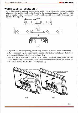
2.(2-A):With two screws (black) (M4/M5/M6), connect to the two holes on the back
of TV set respectively ,then connect the plastic pillar to the two holes on the bottom
with screws(white) (M4/M5/M6).(See figure 2-A)
(2-B):With two screws (black) (M4/M5/M6), connect to the two holes on the back of
TV set respectively ,then connect the metal pillar to the two holes on the downside
with screws (black) (M4/M5/M6).(See figure 2-B)
1-3
2.With four screws (black) (M4/M5/M6/M8), connect to the four holes on the back of TV
set respectively.(See figure 1-2)
1-2
Screws (black) (M4/M5/M6/M8)
3.Hang four screws (black)(M4/M5/ M6/M8) connected to the back of TV on the four
holes of part A;Finally fasten the top of part A with two screws (BM4*30)(white)
(See figure 1-3) The installation is accomplished.
1-1
2-B
Screws (black) (M4/M5/M6)
Screws (black) (M4/M5/M6)
Screws (white) (M4/M5/M6)
Screws (black) (M4/M5/M6)
Plastic pillar
2-A
1.Make 3 holes at the suitable places on the wall for part A, Make 4 holes at the suitable places on the wall for part B,Make 2 holes at the suitable places on the wall for part C, put in plastic particles and then fix part A,part Bor part C on the wall with the screws (6x40). (See figure 1-1)
Wall Mount Installation(2):
SAEG00-E827
260.0114.0
463.0119.0
A
B
C
P-3 P-4 P-5
A
A
A
A
A
B
C
1-3
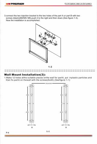
3.connect the two injection bracket to the two holes of the part A or part B with two screws (black)(M4/M5/ M6),push it to the right and then down.(See figure 1-3). Now the installation is accomplished.
1-1
1.Make 12 holes at the suitable places on the wall for part A, put in plastic particles and then fix part A on the wall with the screws(6x40).(See figure 1-1)
Wall Mount Installation(3):
2.(2-A):With two screws (black) (M4/M5/M6), connect to the two holes on the back
of TV set respectively ,then connect the plastic pillar to the two holes on the bottom
with screws(white) (M4/M5/M6).(See figure 2-A)
(2-B):With two screws (black) (M4/M5/M6), connect to the two holes on the back of
TV set respectively ,then connect the metal pillar to the two holes on the downside
with screws (black) (M4/M5/M6).(See figure 2-B)
1-3
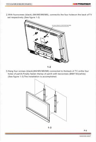
2.With four screws (black) (M4/M5/M6/M8), connect to the four holes on the back of TV
set respectively.(See figure 1-2)
1-2
Screws (black) (M4/M5/M6/M8)
3.Hang four screws (black)(M4/M5/ M6/M8) connected to the back of TV on the four
holes of part A;Finally fasten the top of part A with two screws (BM4*30)(white)
(See figure 1-3) The installation is accomplished.
1-1
2-B
Screws (black) (M4/M5/M6)
Screws (black) (M4/M5/M6)
Screws (white) (M4/M5/M6)
Screws (black) (M4/M5/M6)
Plastic pillar
2-A
1.Make 3 holes at the suitable places on the wall for part A, Make 4 holes at the suitable places on the wall for part B,Make 2 holes at the suitable places on the wall for part C, put in plastic particles and then fix part A,part Bor part C on the wall with the screws (6x40). (See figure 1-1)
Wall Mount Installation(2):
SAEG00-E827
260.0114.0
463.0119.0
A
B
C
P-3 P-4 P-5
A
A
A
A
A
B
C
1-3
3.connect the two injection bracket to the two holes of the part A or part B with two screws (black)(M4/M5/ M6),push it to the right and then down.(See figure 1-3). Now the installation is accomplished.
1-1
1.Make 12 holes at the suitable places on the wall for part A, put in plastic particles and then fix part A on the wall with the screws(6x40).(See figure 1-1)
Wall Mount Installation(3):
2.(2-A):With two screws (black) (M4/M5/M6), connect to the two holes on the back
of TV set respectively ,then connect the plastic pillar to the two holes on the bottom
with screws(white) (M4/M5/M6).(See figure 2-A)
(2-B):With two screws (black) (M4/M5/M6), connect to the two holes on the back of
TV set respectively ,then connect the metal pillar to the two holes on the downside
with screws (black) (M4/M5/M6).(See figure 2-B)
1-3
2.With four screws (black) (M4/M5/M6/M8), connect to the four holes on the back of TV
set respectively.(See figure 1-2)
1-2
Screws (black) (M4/M5/M6/M8)
3.Hang four screws (black)(M4/M5/ M6/M8) connected to the back of TV on the four
holes of part A;Finally fasten the top of part A with two screws (BM4*30)(white)
(See figure 1-3) The installation is accomplished.
1-1
2-B
Screws (black) (M4/M5/M6)
Screws (black) (M4/M5/M6)
Screws (white) (M4/M5/M6)
Screws (black) (M4/M5/M6)
Plastic pillar
2-A
1.Make 3 holes at the suitable places on the wall for part A, Make 4 holes at the suitable places on the wall for part B,Make 2 holes at the suitable places on the wall for part C, put in plastic particles and then fix part A,part Bor part C on the wall with the screws (6x40). (See figure 1-1)
Wall Mount Installation(2):
SAEG00-E827
260.0114.0
463.0119.0
A
B
C
P-3 P-4 P-5
A
A
A
A
A
B
C