Embed Size (px)
Citation preview
Last Updated November 2005
E.3.1 ELECTRICAL SERVICES - TABLE OF CONTENTS UNSW DESIGN & CONSTRUCTION REQUIREMENTS – WEB ENTRY PAGE SECTION A – INTRODUCTION SECTION B – DEVELOPMENT & PLANNING SECTION C – ARCHITECTURAL REQUIREMENTS SECTION D – EXTERNAL WORKS SECTION E.1 – HYDRAULIC SERVICES SECTION E.2 – MECHANICAL SERVICES
E.3.1 ELECTRICAL SERVICES – SCHEDULE OF CHANGES – REVISION 4.1.........4 E.3.1. ELECTRICAL SERVICES ................................................................................. 4
E.3.1.1. Main Switchboards ........................................................................................... 4 E.3.1.1.1. General...................................................................................................... 4 E.3.1.1.2. Operating Conditions .............................................................................. 5 E.3.1.1.3. Materials.................................................................................................... 6 E.3.1.1.4. Treatment Of Metal Surfaces................................................................. 7 E.3.1.1.5. Switchboard Configuration ..................................................................... 7 E.3.1.1.6. Terminations And Connections ............................................................. 8 E.3.1.1.7. Busbars ..................................................................................................... 9 E.3.1.1.8. Temperature Rise Limit ........................................................................ 10 E.3.1.1.9. Main Switches And Isolating Switches ............................................... 10 E.3.1.1.10. Switchboard Control Wiring................................................................ 10 E.3.1.1.11. Air Circuit Breakers ............................................................................. 11 E.3.1.1.12. Moulded Case Circuit Breakers......................................................... 11 E.3.1.1.13. Metering ................................................................................................ 12 E.3.1.1.14. Miscellaneous Switchboard Components ........................................ 13 E.3.1.1.15. Circuit Index.......................................................................................... 14 E.3.1.1.16. Motor Starters And Contactors .......................................................... 14 E.3.1.1.17. Relays.................................................................................................... 14 E.3.1.1.18. Switches ................................................................................................ 15 E.3.1.1.19. Circuit schedule ................................................................................... 15
E.3.1.2. Mechanical Control Centre Board (M.C.C) ................................................. 15 E.3.1.2.1. Construction ........................................................................................... 16 E.3.1.2.2. Material.................................................................................................... 17 E.3.1.2.3. Surface Treatement ............................................................................. 17 E.3.1.2.4. Termination And Connection ............................................................... 18 E.3.1.2.5. Busbars ................................................................................................... 18 E.3.1.2.6. Temperature Rise Limit ........................................................................ 19 E.3.1.2.7. Wiring....................................................................................................... 19 E.3.1.2.8. Moulded Circuit Breakers ..................................................................... 19 E.3.1.2.9. Residual Current Devices..................................................................... 20
UNSW
1/31
Design & Construction Requirements (Rev 4.1)
Last Updated November 2005
E.3.1.2.10. Load-break and switch fuses, motor isolators, fuses. .................... 21 E.3.1.2.11. Contactors & Overloads ..................................................................... 22 E.3.1.2.12. Contactor Coils..................................................................................... 23 E.3.1.2.13. Thermal Overloads .............................................................................. 23 E.3.1.2.14. Electronic Overloads ........................................................................... 23 E.3.1.2.15. Critical Motor Drives ............................................................................ 24 E.3.1.2.16. Electronic Motor Protection Unit........................................................ 24 E.3.1.2.17. Communications .................................................................................. 25 E.3.1.2.18. Thermal Magnetic Over-Current Relay ............................................ 26 E.3.1.2.19. Electronic/Microprocessor Over-Current Relay .............................. 26 E.3.1.2.20. Led Indication ....................................................................................... 26
E.3.1.3. Locking and Labelling .................................................................................... 26 E.3.1.3.1. Locking .................................................................................................... 26 E.3.1.3.2. Labelling .................................................................................................. 27 E.3.1.3.3. Locations of the Labels......................................................................... 27 E.3.1.3.4. Label Elements ...................................................................................... 28 E.3.1.3.5. Electrical Fixtures Circuit Labelling ..................................................... 28
E.3.1.4. General Purpose Outlets ............................................................................... 29 E.3.1.4.1. Types Of Outlet ...................................................................................... 29 E.3.1.4.2. General Purpose Outlets ...................................................................... 29 E.3.1.4.3. Accessories ............................................................................................ 30 E.3.1.4.4. Mounting Arrangements ....................................................................... 30 E.3.1.4.5. Labels, Signs And Notices ................................................................... 30 E.3.1.4.6. Distribution Boards ................................................................................ 30
E.3.1.5. Testing and Commissioning .......................................................................... 31
SECTION E.3.2 – LIGHTING SECTION E.3.3 – SPECIAL SYSTEMS SECTION E.3.4 – HIGH VOLTAGE SECTION E.4 – COMMUNICATIONS SECTION E.5 – LIFTS SECTION E.6 – FUME CUPBOARDS SECTION F – SPECIFIC AREA REQUIREMENTS APPENDIX 1 – BUILDING AUTOMATION AND CONTROL SYSTEMS SPECIFICATION APPENDIX 2 – CONCRETE FOR STRUCTURES APPENDIX 3 – UNSW CONTROL SYSTEM STANDARDS HVAC
UNSW
2/31
Design & Construction Requirements (Rev 4.1)
Last Updated November 2005
APPENDIX 4 – DOCUMENT REQUIREMENTS APPENDIX 5 – UNSW STANDARD PRELIMINARIES APPENDIX 6 – SECURITY SYSTEMS
UNSW
3/31
Design & Construction Requirements (Rev 4.1)
Last Updated November 2005
E.3.1 ELECTRICAL SERVICES – SCHEDULE OF CHANGES – REVISION 4.1 As a guide only, attention is drawn to changes that have been made in the following clauses since the last revision Clause Date General revision E.1.1.7 August 2004 E.3.1.2 MCC section reinstated November 2005
E.3.1. ELECTRICAL SERVICES
E.3.1.1. Main Switchboards
E.3.1.1.1. General The switchboard shall be segregated (as a minimum) into the following sections and circuits:
a) Non Essential Services
b) Lighting (internal and external)
c) General Power
d) Plant, Equipment and Process Heating
e) Essential Services
f) Lighting
g) General Power
h) Plant, Equipment and Process Heating Each circuit shall have a minimum of 25% minimum spare capacity for space and maximum demand. The switchboard shall be the product of a well-established switchboard manufacturer and shall be of the dead front, totally enclosed type. . The switchboard shall have a degree of protection of IP43, for interior use and IP 56 for external use. The switchboard is to be floor mounted on a galvanised steel plinth. The switchboard shall incorporate an earth bar and a neutral link. UNSW
4/31
Design & Construction Requirements (Rev 4.1)
Last Updated November 2005
Protective devices shall be interconnected by a three-phase busbar assembly that is independently supported off the switchboard enclosure. Pay particular attention to cabling space around the circuit breaker assembly, and Current Transformers Space around Current Transformers for any maintenance or replacement shall be included The switchboards shall be of a modular layout having sections of standard current rated functional units related to the main busbar and busbar dropper systems in a regular fashion. The design shall be the same as a type of switchboard that has been verified as complying with the type tests specified in Section 8 of AS3439.1 the switchboard be a TTA. Type test certificates shall be submitted with detailed particulars of the equipment tested by an approved Testing Authority. The manufacturer of the type-tested equipment shall be the manufacturer of the proposed equipment. Should the type test documents not be available, or be inappropriate to the actual design, submit the switchboards for type testing by a NATA approved Testing Authority at no cost to the Principal and within the construction program for the contract. The Project Officer shall be notified in writing of the name of the proposed manufacturer of switchboards before any work or drawings are commenced. The manufacturer shall provide the UNSW the Temperature rise requirement stated in AS3439 prior to any work being started.
E.3.1.1.2. Operating Conditions The switchboard shall comply with the requirements of AS3439.1 with the following specific Conditions Of Operation to appendix BB:
a) Supply is 415/240V, 3 phase, 4 wire, 50Hz, MEN solidly earthed.
b) Control circuit voltage is 240V.
c) Maximum fault level of the assembly shall be:
d) 63 kA r.m.s. symmetrical ,
e) 95 kA peak Minimum for
f) Space available: 25%.
g) Segregation required is form 3b. Preferred method of connection of equipment is Front connected (unless otherwise approved by FM Engineering).
UNSW
5/31
Design & Construction Requirements (Rev 4.1)
Last Updated November 2005
Automatic power factor correction brand shall be supplied, (Note: protection against capacitor damage by harmonics is required). Front connected provisions (unless otherwise approved by FM Engineering).
a) Provision for connection of stand-by generator.
b) Type tested design to AS 3439.1.
c) Preferred arrangement is in line.
d) Rated short time withstand current of bus-bars required is 63 kA r.m.s. for one second.
e) Diversity factor for load circuits is as per Table 1, AS3439.1.
f) Degree of protection is IP43for interior or IP56 for external usage.
g) Form of segregation required is Form 3.b
h) Possible future extensions are from one end.
i) Service and Installation Conditions Not exceeding the limits of clause 6.1, AS3439.1.
j) Switchboard safety measures shall be by mechanical means (AS3439.1 clause 7.4.2.2 Protection by barriers or enclosures) including mechanical interlocking of doors and access by tool rather than key.
k) Graded protection (upstream & downstream).
l) Full sized neutral.
m) The switchboard shall be insect and vermin proof.
n) The switchboard shall be finished Orange external; White internal.
o) The switchboard shall be mounted on or incorporate a 100 mm high galvanised steel plinth.
Submit detailed drawings, including single line diagram, of the main switchboard to the Supply Authority for approval prior to manufacture and co-ordinate the Supply Authority during the inspection of the completed switchboard to ensure compliance with their requirements.
E.3.1.1.3. Materials All sheet steel used in the manufacture of the switchboards shall be cold rolled, commercial, bright mild steel, free from rust and blemishes. All structural sections used for frameworks or supports shall be first grade mild steel, truly straight and shall be thoroughly descaled and degreased. All welds shall be full fillet welds ground smooth and free of weld spatter and wire brushed clean. Minimum thickness of steel sheets shall be as follows:
UNSW
6/31
Design & Construction Requirements (Rev 4.1)
Last Updated November 2005
For back and sides of cabinets, cubicles, etc. - 1.6 mm. For front and top - Diagonal not longer than 600 mm - 1.6 mm. Diagonal not longer than 900 mm - 2.5 mm.
Steel thickness less than 2.0 mm and 2.5 mm may be used provided the panels are stiffened by dishing, folding or bracing, but only after approval is obtained from the Superintendent. Interchange ability of parts and equipment shall be maintained wherever practicable. Metal parts shall be machined where necessary for accurate fit and good appearance. All bolts, screws, etc., whether used in assembling equipment or fixing it in place, shall be galvanised or made from corrosion resistant metal. Where visible on front of panels, they will be chromium plated, not cadmium plating. Door hinges shall be of a lift-off type and for outdoor applications shall be zinc coated and fitted with hinge pins of bronze or other corrosion resistant material. Door handles shall be chromium plated and shall incorporate a barrel type lock mechanism.
E.3.1.1.4. Treatment Of Metal Surfaces The surfaces of switchboard enclosures shall be painted. The colour of finishes shall be as follows: White enamel internally for both indoor and outdoor application. Orange enamel externally, colour number N42 to AS 2700 for indoor application.
E.3.1.1.5. Switchboard Configuration The items described herein shall be included in the design, manufacture and installation of all switchboards. UNSW FM Engineering must be given notice in writing of the name of the proposed manufacturer of the switchboard/s before any works and/or drawings are commenced. Conduits and ducts shall be securely attached to the switchboard/s utilising pre-punched conduit knockouts or removable gland plates. Where space is provided for future breakers, fuses, etc., the switchboard/s shall be fitted with the necessary bus-bars and connections to facilitate the future fitting of additional equipment without disturbance to the existing installation. Where this involves provision of unused lengths of bus-bar, this bus-bar shall be adequately supported. The
UNSW
7/31
Design & Construction Requirements (Rev 4.1)
Last Updated November 2005
escutcheon (if any) shall be cut for the future equipment and suitable filler pieces provided. Equipment shall be firmly supported, symmetrically and neatly mounted and all wiring shall be neatly run and supported. Connections between various pieces of equipment shall be copper bus- bar. Terminate all incoming and outgoing cables using crimp type cable lugs or tunnel type terminals. Doors shall be dust sealed by neoprene gaskets and ventilation openings shall be gauze screened to prevent dust and insect entry. Doors and escutcheon panels shall cover all front adjustable settings of circuit breakers, relays and contactors. Where multiple conduits and/or ducts, which would otherwise be visible, enter a wall-mounted switchboard they shall be covered by a removable sheetmetal panel folded and finished to match the switchboard. Alternatively, approved timber panels may be installed. Cables and conduits run from the top and bottom of the switchboards to the floor slab below and ceiling space above shall be enclosed in neat metal duct. Ductwork shall be not less than 1 mm thick in any case. Metal ducts shall be zincanneal of suitable thickness and painted. Pop rivets shall be used for all joints. Where conduits or ducts required to be concealed enter a wall-mounted switchboard they shall enter the switchboard through a metal box recessed into the wall and located behind the board. Wall mounted switchboards shall be mounted approximately 2 m from top of board to floor.
E.3.1.1.6. Terminations And Connections Switchboards shall be complete with cable terminating boxes/glands mounted to provide ample space for making off the cable terminations; install insulated tails from these terminations to the associated switchgear and fix the tails securely to prevent any displacement. Switchboards shall be complete with cable lugs mounted on the switchgear studs, bus-bars, extension flags etc. for all connections rated at 200A and above. Any incoming or existing cable running from the top of the switchboards to the floor slab above shall be enclosed within a ductwork. Type of ductwork shall be not less than 1mm thick and in any case shall be zinc annealed.
UNSW
8/31
Design & Construction Requirements (Rev 4.1)
Last Updated November 2005
E.3.1.1.7. Busbars Requirement: Busbar circuits within the switchboard, extend from the termination of the incoming unit to the line side of protective equipment for outgoing circuits. The whole busbars installation horizontal, vertical and dropper shall be fully insulated. Where dual incoming feeds are provided, the main busbar system shall be in two sections with each incoming feed supplying a corresponding bus section. The outgoing circuits distributed evenly between the two sections. A bus section circuit breaker or switch shall be provided so that it is possible to energise both bus sections through one feed only. Segregation: Where a switchboard requires “essential” and “non-essential” circuits divide the busbar system into separate ‘essential’ and ‘non-essential’ circuits, each segregated from the other by fixed and continuous barriers. Clearly label each segregated section of the busbar system. Standards: To As 3768, As 3865 And As 4388. Definitions: Busbars connecting incoming terminals to line side terminals of main. Busbars connecting incoming functional unit terminals, or incoming busbars where no main switches are included, to outgoing functional unit terminals or outgoing functional unit tee-offs. Tee-off busbars: Busbars connecting main busbars to incoming terminals of outgoing functional units. Material: Hard-drawn high-conductivity electrolytic tough pitched copper alloy bars. Busbar Insulation and Protection: The whole Busbar configuration layout shall be insulated and be in accordance with AS 3439.1. Full size neutral shall be installed. The whole busbars installation vertical and dropper shall be fully insulated.
a) Type of Insulation: shall be polythene at least 0.4 mm thick with dielectric strength of 2.5kV rms for I min, applied by fluid bed process in which the material is phase coloured and directly cured on to the bars. Close fitting moulding insulation mouldings at least 1mm thick. Use heat shrink material only around edges of the busbar.
b) Taped joints: Apply non-adhesive stop-off type tape, coloured to match adjacent insulation and half lapped to achieve a thickness at least that of the solid insulation.
Neutral busbars and joints: Select from the following:
UNSW
9/31
Design & Construction Requirements (Rev 4.1)

Last Updated November 2005
Polyethylene: At least 0.4mm thick with dielectric strength of 2.5 kV r.m.s. for 1 min, applied by a fluidised bed process in which the material is phase coloured and directly cured onto the bars. Close fitting busbar insulation mouldings at least 1mm thick. Heat shrink material: Use only on rounded edge busbars. Taped joints: Apply non-adhesive stop-off type tape, coloured to match adjacent insulation and half lapped to achieve a thickness at least that of the solid insulation.
E.3.1.1.8. Temperature Rise Limit The manufacturer shall provide all Temperature Rise test as designed. The Manufacture shall provide the Temperature Rise requirement stated in AS3439.1
E.3.1.1.9. Main Switches And Isolating Switches Main switches on main switchboards and isolating switches on distribution switchboards and in other locations shall comply with AS1775 and shall be suitable for fault making and load breaking duties. Switchgear and Control Gear Assembly incoming isolators shall have the same fault capacity as the assembly busbar system unless otherwise specified. Unless otherwise specified, the following requirements shall apply: Type of switching shall be independent manual operation. Rated duty shall be uninterrupted duty for non-ventilated enclosure. Indicated fault capacity refers to the rated short time withstand current. Utilisation category shall be AC-23. Incorporate a primary indication of the ON and OFF positions. Incorporate a secondary indication of the ON and OFF positions on the switch body where the operating handle is not a fixed part of the switch.
E.3.1.1.10. Switchboard Control Wiring Control wiring shall be stranded conductor of minimum size 7/0.50. TPI. Flexible connections to door mounted equipment shall be 30/.025 TPI flexible cord. (Wiring systems other than the above may be accepted -particularly for connection of solid-state components - however such departures will be by approval of the Superintendent only). Differentiate between ac. and dc. conductors by continuous colour coding of the insulation. Identify each end of every conductor by slip on ferrules (not clips) numbered to correspond with the circuit drawings.
UNSW
10/31
Design & Construction Requirements (Rev 4.1)
Last Updated November 2005
Install multiple runs of control cable in slotted plastic ducting that shall be complete with clip on covers. Terminate all incoming and outgoing control circuit cables using crimp lugs on numbered rail mounted clip-on terminal blocks.
E.3.1.1.11. Air Circuit Breakers Air circuit breakers shall be in accordance with AS1930; they shall be suitable for operation on 415V, 50 Hz systems and shall be rated for continuous operation as indicated on the drawings. Drawings are to be enclosed in the switchboard. The main incoming ACB shall be capable of withdrawal and interlocked so that withdrawal or reconnection can be done only with the circuit breaker in the open position. Air circuit breakers shall have the following monitoring system:
a) Single phase indication selectable for each phase
b) Earth fault current
c) Reverse power indication
d) Line voltage
e) Trip current and operating time
f) Availability of transmitting data to a PC
E.3.1.1.12. Moulded Case Circuit Breakers Specify current ratings for all moulded case circuit breakers. Moulded case circuit breakers shall be of one manufacture Circuit breakers having a current rating not exceeding 100A and current breaking capacity less than 10 kA, shall comply with AS3111. The manufacture shall demonstrate via calculation that of temperature use impact on each switchgear will not detriment the rating of the switchgear. The size and mounting arrangements shall be such as to permit interchange of single pole and three pole breakers of the same frame size.
UNSW
11/31
Design & Construction Requirements (Rev 4.1)
Last Updated November 2005
Circuit breakers with current breaking capacities of 10 kA and above shall comply with AS2184. Circuit breaker trip ratings shall be labelled or inscribed on the circuit breaker body and shall be clearly visible with the switchboard escutcheon cover in place. Shall be mounted in the card index holder in the cubical door for each board. Enclose the circuit index with a clear Perspex cover. Fuses or circuit breakers shall be numbered as shown on the circuit index. The board shall be clearly zoned by subscribing or neat painting or other approved means. Adhesive tapes are NOT acceptable. Each zone shall be clearly labelled using white lettering minimum 10mm high on black labels of same material.
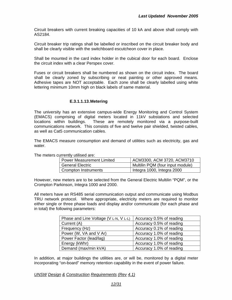
E.3.1.1.13. Metering The university has an extensive campus-wide Energy Monitoring and Control System (EMACS) comprising of digital meters located in 11kV substations and selected locations within buildings. These are remotely monitored via a purpose-built communications network. This consists of five and twelve pair shielded, twisted cables, as well as Cat5 communication cables. The EMACS measure consumption and demand of utilities such as electricity, gas and water. The meters currently utilised are:
Power Measurement Limited ACM3300, ACM 3720, ACM3710 General Electric Multilin PQM (four input module) Crompton Instruments Integra 1000, Integra 2000
However, new meters are to be selected from the General Electric Multilin “PQM”, or the Crompton Parkinson, Integra 1000 and 2000. All meters have an RS485 serial communication output and communicate using Modbus TRU network protocol. Where appropriate, electricity meters are required to monitor either single or three phase loads and display and/or communicate (for each phase and in total) the following parameters:
Phase and Line Voltage (V L-N, V L-L) Accuracy 0.5% of reading Current (A) Accuracy 0.5% of reading Frequency (Hz) Accuracy 0.1% of reading Power (W, VA and V Ar) Accuracy 1.0% of reading Power Factor (lead/lag) Accuracy 1.0% of reading Energy (kWhr) Accuracy 1.0% of reading Demand (max/min kVA) Accuracy 1.0% of reading
In addition, at major buildings the utilities are, or will be, monitored by a digital meter incorporating “on-board” memory retention capability in the event of power failure.
UNSW
12/31
Design & Construction Requirements (Rev 4.1)

Last Updated November 2005
For this purpose a meter such as the “GE” PQM meter is generally used, the version required incorporates the four input module, permitting pulse measurements.
a) Gas Consumption
b) Gas pressure
c) Water consumption
d) Electricity
e) Energy usage
f) Maximum Demand
g) Volts, amps, kVA, kW, kVAr, power factor The EMACS meter panels contain (where existing), or need to be provided with (where new metering is required) digital meters, together with approved terminal strips for data cables, CT wiring and shorting links, power supplies, fuses or circuit breakers. All meters have current inputs limited to 5A. Hence, current transformers (CTs) must be provided with 5A secondaries, with a rated classification of 0.5M. From each of the two CT secondary terminals, a cable shall be run to the EMACS metering panel shortening links, i.e. two cables from each CT. Each meter is required to be provided with an individual calibration certificate. NOTE: Tenderers and contractors are required to clearly demonstrate how they are able to incorporate the EMACS and these meters within their overall BACS operation, providing full functionality and remote monitoring. Details to be discussed with Engineering Servtheices Project Officer. Section Number and location of those meters shall be approved by UNSW Energy Manager prior construction.
E.3.1.1.14. Miscellaneous Switchboard Components Indicating Instruments The main switchboard and main distribution board shall be fitted with an electronic meter for current, voltage, watts & power factor. The meter shall be an IQ Data Plus from Email Westinghouse or similar. Indicating Lights Indicating lights shall be coloured in accordance with AS1431 and shall have a "Lamp Test" button facility. Push Buttons Push buttons shall be coloured in accordance with AS1431. Terminals Terminals shall be clip-in rail mounting and mounted not less than 400 mm from bottom of board.
UNSW
13/31
Design & Construction Requirements (Rev 4.1)
Last Updated November 2005
Surge Protection Devices Surge protection devices shall protect all phases and neutral. Surge protection devices shall be provided Critec Movtec MT-275V/120K connected between active conductors and earth and between neutral and earth. Power Factor Correction Equipment Power factor correction equipment is to be provided and capable of maintaining the power factor to 0.97 min.
E.3.1.1.15. Circuit Index The fuses or circuit breakers shall be numbered and correspond as shown on the as installed drawings. A neatly typed circuit list giving number, rating and circuit function shall be mounted in the card index holder in the cubicle door for each board. Enclose the circuit index with a clear perspex cover. Fuses or circuit breakers shall be numbered as shown on the circuit index. The board shall be clearly zoned by scribing or neat painting or other approved means. Adhesive tapes are NOT acceptable. Each zone shall be clearly labelled using white lettering minimum 10 mm high on black labels of same material.
E.3.1.1.16. Motor Starters And Contactors Motor starters shall be of the magnetic contactor type, fitted with triple pole double break contacts and thermal overload protection on each pole. Overload protection shall be of the differential single-phase protection type. Overload protection shall be sized suitable for adjusting the set point sufficiently low enough to test operation. Under no circumstances will relays be accepted as motor starters or power duty of any kind. Motor starting and other contactors shall comply with AS 1029 and AS 1202 or the equivalent local standard. Selection of motor starters and contactors shall be according to the duty required. All contactors shall be noise-free when energised
E.3.1.1.17. Relays All relays shall be plug-in type. Fit relays with clear plastic dustproof covers that enclose the complete relay. Use contactors for switching current in excess of 6A. Contactors used as relays shall have clear plastic dustproof covers that enclose the complete assembly. Provide twin contact spring sets for relays used for light duty switching (under 1A).
UNSW
14/31
Design & Construction Requirements (Rev 4.1)
Last Updated November 2005
Use the constant resistance contact type, eg. gold contact or reed relays for where relay contacts are to be used for mixed voltages, contacts shall be adequately isolated from each other. Clearly mark voltage type on each contactor, eg. 24 V.D.C, 240 V.A.C.
E.3.1.1.18. Switches For Mechanical Services and Hydraulic Services control systems, all manual switches except main switches shall be the rotary type suitable for the voltage and current controlled.
E.3.1.1.19. Circuit schedule The outgoing circuits shall be numbered sequentially on each distribution board. The UNSW will supply a floppy disk in Microsoft Excel format for the Contarctor to fill in and return ti the UNSW. The Contractor shall also supply a hard copy of each Circuit Schedule fitted in a Perspex covered holder in each distribution board.
E.3.1.2. Mechanical Control Centre Board (M.C.C) The switchboard shall be the product of a well-established switchboard manufacturer and shall be of the dead front, totally enclosed type. (See also clause "Switchboards Generally"). Modular switchboard configuration will not be accepted. The switchboard shall have a degree of protection of IP43, for interior use and IP 56 for external use. Protective devices shall be interconnected by a three-phase busbar assembly that is independently supported off the switchboard enclosure. Pay particular attention to cabling space around the circuit breaker assembly, and Current Transformers Space around Current Transformers for any maintenance or replacement shall be included The switchboards shall be of a modular layout having sections of standard current rated functional units related to the main busbar and busbar dropper systems in a regular fashion. The design shall be the same as a type of switchboard that has been verified as complying with the type tests specified in Section 8 of AS3439.1 UNSW FM Engineering must be given notice in writing of the name of the proposed manufacturer of the switchboard/s before any works and/or drawings are commenced.
UNSW
15/31
Design & Construction Requirements (Rev 4.1)

Last Updated November 2005
The Manufacturer shall provide the Temperature Rise requirement stated in AS3439.1To FM Engineering prior any work start The switchboard shall comply with the requirements of AS3439.1 with the following specific Conditions Of Operation to appendix BB: All MCCB should have true RMS monitoring and will be unaffected by harmonics in the system, up to including the 19th harmonic
E.3.1.2.1. Construction Supply is 415/240V, 3 phase, 4 wire, 50Hz, MEN solidly earthed. Control circuit voltage is 240V. Maximum fault level of the assembly shall be a minimum: 20kA r.m.s. symmetrical. Space available: 25%. Segregation required is form 2 The contractor/ shall provide to UNSW FM Engineering all calculation in relation to fault level prior any design, or construction. Any design/construction of MCC board which has not been accepted in writing by UNSW FM Engineering will be rejected. Preferred method of connection of equipment is Front connected (unless otherwise approved by FM Engineering Section). Preferred arrangement is in line. Rated short time withstand current of bus-bars required is 20kA r.m.s. for one second. minimum Diversity factor for load circuits is as per Table 1, AS3439.1. Degree of protection is IP42for interior or IP56 for external usage. Form of segregation required is Form 2 Possible future extensions shall be considered when MCC board is designed M.C.C board shall have physical barrier between the isolating unit/ circuit protection and the main busbar arrangement. Segregation shall by means of approved sheet metal Physical barrier shall be installed between all. isolating unit/circuit protection/busbar arrangement with control units/stop/start switches and indicting lights All equipment mounting cubicles shall be by means of hinged lockable doors. Full sized neutral. The switchboard shall be insect and vermin proof. The switchboard shall be finished Orange external; White internal. The switchboard shall be mounted on or incorporate a 100 mm high galvanised steel plinth. Submit detailed drawings, including single line diagram, of the main switchboard to the Supply Authority for approval prior to manufacture and co-ordinate the Supply Authority during the inspection of the completed switchboard to ensure compliance with their requirements.
UNSW
16/31
Design & Construction Requirements (Rev 4.1)

Last Updated November 2005
E.3.1.2.2. Material All sheet steel used in the manufacture of the switchboards shall be cold rolled, commercial, bright mild steel, free from rust and blemishes. All structural sections used for frameworks or supports shall be first grade mild steel, truly straight and shall be thoroughly descaled and degreased. All welds shall be full fillet welds ground smooth and free of weld spatter and wire brushed clean. Minimum thickness of steel sheets shall be as follows: For back and sides of cabinets, cubicles, etc. - 1.6 mm. For front and top - Diagonal not longer than 600 mm - 1.6 mm. Diagonal not longer than 900 mm - 2.5 mm.
Steel thickness less than 2.0 mm and 2.5 mm may be used provided the panels are stiffened by dishing, folding or bracing, but only after approval is obtained from the Superintendent. Interchange ability of parts and equipment shall be maintained wherever practicable. Metal parts shall be machined where necessary for accurate fit and good appearance. All bolts, screws, etc., whether used in assembling equipment or fixing it in place, shall be galvanised or made from corrosion resistant metal. Where visible on front of panels, they will be chromium plated, not cadmium plating. Door hinges shall be of a lift-off type and for outdoor applications shall be zinc coated and fitted with hinge pins of bronze or other corrosion resistant material. Door handles shall be chromium plated and shall incorporate a barrel type lock mechanism
E.3.1.2.3. Surface Treatement The surfaces of switchboard enclosures shall be painted. The colour of finishes shall be as follows: White enamel internally for both indoor and outdoor application. Orange enamel externally, colour number N42 to AS 2700 for indoor Doors shall be dust sealed by neoprene gaskets and ventilation openings shall be gauze screened to prevent dust and insect entry. Doors and escutcheon panels shall cover all front adjustable settings of circuit breakers, relays and contactors.
UNSW
17/31
Design & Construction Requirements (Rev 4.1)
Last Updated November 2005
E.3.1.2.4. Termination And Connection Switchboards shall be complete with cable terminating boxes/glands mounted to provide ample space for making off the cable terminations; install insulated tails from these terminations to the associated switchgear and fix the tails securely to prevent any displacement. Switchboards shall be complete with cable lugs mounted on the switchgear studs, bus-bars, extension flags etc. for all connections rated at 200A and above. Equipment shall be firmly supported, symmetrically and neatly mounted and all wiring shall be neatly run and supported. Connections between various pieces of equipment shall be copper bus- bar. Terminate all incoming and outgoing cables using crimp type cable lugs or tunnel type terminals. Any incoming existing or new cables running from the top of the switchboards to the floor slab above shall be enclosed within a Ductwork. Type of Ductwork shall be not less than 1 mm thick in any case and shall be zinc anneal type.
E.3.1.2.5. Busbars Requirement: Busbar circuits within the switchboard, extend from the termination of the incoming unit to the line side of protective equipment for outgoing circuits. The whole busbars installation horizontal, vertical and dropper shall be fully insulated Standards: To As 3768, As 3865 And As 4388. Definitions: Busbars connecting incoming terminals to line side terminals of main. Busbars connecting incoming functional unit terminals, or incoming busbars where no main switches are included, to outgoing functional unit terminals or outgoing functional unit tee-offs. Tee-off busbars: Busbars connecting main busbars to incoming terminals of outgoing functional units. Material: Hard-drawn high-conductivity electrolytic tough pitched copper alloy bars. Busbar Insulation and Protection: The whole Busbar configuration layout shall be insulated and be in accordance with AS 3439.1, including the earth busbar configuration. The whole busbars installation vertical and dropper shall be fully insulated. Type of insulation: Polyethylene: At least 0.4mm thick with dielectric strength of 2.5 kV r.m.s. for 1 min, applied by a fluidised bed process in which the material is phase coloured and directly cured onto the bars.
UNSW
18/31
Design & Construction Requirements (Rev 4.1)
Last Updated November 2005
Close fitting busbar insulation mouldings at least 1mm thick. Heat shrink material: Use only on rounded edge busbars. Taped joints: Apply non-adhesive stop-off type tape, coloured to match adjacent insulation and half lapped to achieve a thickness at least that of the solid insulation. Neutral busbar: Full size neutral shall be installed. Select and shall be fully insulated
E.3.1.2.6. Temperature Rise Limit The manufacturer shall provide all Temperature Rise test as designed. The Manufacture shall provide the Temperature Rise requirement stated in AS3439.1
E.3.1.2.7. Wiring Control wiring shall be stranded conductor of minimum size 7/0.50. TPI. Flexible connections to door mounted equipment shall be 30/.025 TPI flexible cord. (Wiring systems other than the above may be accepted -particularly for connection of solid-state components - however such departures will be by approval of the Superintendent only). Differentiate between ac. and dc. conductors by continuous colour coding of the insulation. Identify each end of every conductor by slip on ferrules (not clips) numbered to correspond with the circuit drawings. Install multiple runs of control cable in slotted plastic ducting that shall be complete with clip on covers. Terminate all incoming and outgoing control circuit cables using crimp lugs on numbered rail mounted clip-on terminal blocks.
E.3.1.2.8. Moulded Circuit Breakers Specify current ratings for all moulded case circuit breakers. Moulded case circuit breakers shall be of one manufacture Circuit breakers having a current rating not exceeding 100A and current breaking capacity less than 10 kA, shall comply with AS3111. The manufacture shall demonstrate via calculation that of temperature use impact on each switchgear will not detriment the rating of the switchgear.
UNSW
19/31
Design & Construction Requirements (Rev 4.1)
Last Updated November 2005
The size and mounting arrangements shall be such as to permit interchange of single pole and three pole breakers of the same frame size. Circuit breakers with current breaking capacities of 10 kA and above shall comply with AS2184. Circuit breaker trip ratings shall be labelled or inscribed on the circuit breaker body and shall be clearly visible with the switchboard escutcheon cover in place. All miniature circuit breakers (MCB’s) shall be NHP Terasaki Din T or approved equal. 10 and 15kA devices shall comply with IEC 947-2 (AS 3947) Standard. Where applicable they should be distinguished with one of the following instantaneous magnetic trip type characteristics. Type C - Usual loads such as: - Lighting - GPO’s - Small motors Type D - Control and protection of circuit having important transient inrush currents (large motors) Miniature circuit breakers shall be capable of field installation of clip-on accessories such as shunt trip, auxiliary / alarm switches, RCD blocks. Earth Leakage Relays All earth leakage relays shall be NHP Terasaki Din-Safe-R Delta (DSR…DEL) or approved equal. Relays will be suitable for use with an independent ring current transformer (toroid) of the same manufacturer. Relays shall have adjustable sensitivity IΔn and trip delay, selectable via selector switches accessible via the front face of the relay. Mounting method will be Din rail or panel mount to suit the application. LED’s will indicate power on, trip status of relay and leakage current as % of the IΔn set point. Relays shall include a test function to check the combined integrity of the relay and toroid connections. Ring Current Transformer (toroid) Selection of the correct toroid shall be in accordance with published tables in Manufacturer technical literature and shall consider IΔn minimum, I maximum and toroid window diameter.
E.3.1.2.9. Residual Current Devices RCCB – Residual Current Operated Circuit Breaker Without Integral Overcurrent Protection
UNSW
20/31
Design & Construction Requirements (Rev 4.1)
Last Updated November 2005
All RCCBs shall comply with IEC 1008 (AS 3190) Standard and carry an appropriate state regulatory prescribed approval No. The RCCB shall have a current rating capable of interrupting the connected load between 40 – 100 A, 2 or 4 Pole. All RCCBs will have an integral test button to test the functioning of the earth leakage detection circuit. RCCB shall accept Din T side mounted auxiliary / alarm contacts. RCBOs - Residual current operated circuit breaker with integral over current protection. RCBOs Din T All RCBO’s shall comply with IEC 1009 (AS 3898 AS 3190) Standard and carry on an appropriate state regulatory prescribed approval No. RCBO’s shall be of the fixed thermal magnetic type with fixed earth leakage sensitivity (IΔn) and trip time characteristics. RCBOs should be capable of field installation of clip on accessories such as shunt trip and auxiliary and alarm switches. They shall meet the back-up and selectivity criteria when used downstream with moulded case circuit breakers (MCCB) in accordance with published tables from manufacturer technical literature.
E.3.1.2.10. Load-break and switch fuses, motor isolators, fuses. General All load-break & combination switch fuses should be of robust quality design and construction and be tested according to IEC947-3. They should be designed to perform as switch disconnectors, motor circuit switches with AC ratings up to 1000 volt, main switches, local safety isolators and bus ties. They should be padlockable in the off position and when in this position, both sides of the fuse link (in the case of switch fuse units) shall be isolated. Switch fuse 32 A and greater, and load-break switches 45 A and greater shall have positive drive contact position indication and quick-make/quick-break mechanisms, independent of the operator’s speed. All switches must provide a high standard of shrouding preferably as standard. Fuse shrouds on switch fuses shall be integral and hinged to avoid misplacing when fuses are changed. All line and load terminals shall be able to be shrouded to avoid accidental touch to a protection rating of IP 20. Unshrouded conductors on the front of the switch are unacceptable. They shall be Stromberg OT, OETL or OS, OESA Series or approved equal. Operational Durability UNSW
21/31
Design & Construction Requirements (Rev 4.1)
Last Updated November 2005
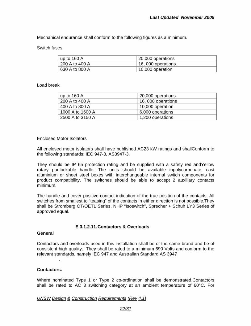
Mechanical endurance shall conform to the following figures as a minimum. Switch fuses
up to 160 A 20,000 operations 200 A to 400 A 16, 000 operations 630 A to 800 A 10,000 operation
Load break
up to 160 A 20,000 operations 200 A to 400 A 16, 000 operations 400 A to 800 A 10,000 operation 1000 A to 1600 A 6,000 operations 2500 A to 3150 A 1,200 operations
Enclosed Motor Isolators All enclosed motor isolators shall have published AC23 kW ratings and shallConform to the following standards; IEC 947-3, AS3947-3. They should be IP 65 protection rating and be supplied with a safety red andYellow rotary padlockable handle. The units should be available inpolycarbonate, cast aluminium or sheet steel boxes with interchangeable internal switch components for product compatibility. The switches should be able to accept 2 auxiliary contacts minimum. The handle and cover positive contact indication of the true position of the contacts. All switches from smallest to “teasing” of the contacts in either direction is not possible.They shall be Stromberg OT/OETL Series, NHP “Isoswitch”, Sprecher + Schuh LY3 Series of approved equal.
E.3.1.2.11. Contactors & Overloads General Contactors and overloads used in this installation shall be of the same brand and be of consistent high quality. They shall be rated to a minimum 690 Volts and conform to the relevant standards, namely IEC 947 and Australian Standard AS 3947
. Contactors. Where nominated Type 1 or Type 2 co-ordination shall be demonstrated.Contactors shall be rated to AC 3 switching category at an ambient temperature of 60°C. For
UNSW
22/31
Design & Construction Requirements (Rev 4.1)
Last Updated November 2005
contactors above 250 kW, AC 3 ratings at 55 °C will be allowed providing operation at 60 °C is acceptable with a de-rating of no more than 15% applied.
E.3.1.2.12. Contactor Coils For contactors up to 55 kW standard AC coils are preferred. For contactors above 55kW AC controlled, contactors with DC coil mechanisms shall be used. The DC coilsshall be controlled via an electronic circuit to precisely control the pick up and dropout voltages of the contactor coil. It must not be possible for the contactors to“chatter”. Maximum pick up power for these contactors shall not exceed 700 VA to minimise burden on the supply. Contactor coils above 250 kW shall have facilities for adjusting the drop out times on loss of supply. The pick up power shall not exceed 2500 VA. All contactor coils must be accessible from the front of the contactor. Contactors shall be Sprecher + Schuh type or an approved equal.
E.3.1.2.13. Thermal Overloads Thermal and electronic overloads must be of the same brand as the contactors. For currents up to 90 amps, directly heated thermals or electronics can be used. Above 90 amps the thermal overloads must be current transformer operated. Electronic overloads can be used providing they comply with clause 5.4 Thermal overloads must be of the ambient temperature compensated type and for motors above 7.5 kW, must have a differential mechanism for phase loss protection. They shall be provided with a test facility and a N/C and N/O auxiliary contact. They shall be Sprecher + Schuh type CT 3 or CT 3 K, CT 7 or approved equal.
E.3.1.2.14. Electronic Overloads Electronic overloads must be used above 110 kW but can be additionally be used on all drives, where nominated, in place of standard thermal overloads. Electronic overloads must also be the same brand and manufacture as the contactors for mechanical compatibility. Whenever possible, electronic overloads must be fitted directly to the contactors. Electronic overloads for drives above 11 kW shall include the following functions andcan be constructed with integral current transformers.
15 selectable trip curves
Test button
Current adjustment in 1 amp steps
Optional thermistor relay function
UNSW
23/31
Design & Construction Requirements (Rev 4.1)
Last Updated November 2005
Trip cause indication retained on power loss less than 30 minutes
Remote electrical reset facility
Phase asymmetry detection
E.3.1.2.15. Critical Motor Drives High level electronic relays shall be used on critical motors and shall be standard on all drives above 350 kW. Such drives must comply with a separate specification written for that purpose and forming part of this set of specifications.
E.3.1.2.16. Electronic Motor Protection Unit. The motor protection units will be required to comply with the following standards and tests:
Impulse Voltage Withstand to IEC 255.4 Appendix E
High Frequency Disturbance to IEC 225.4 Appendix E
Noise Emission to EMC Standard EN 50082-1/2
Noiseproof to EMC Standard EN 50082-1/2
Electrical Test
Motor Circuit to IEC 947-1 Uimp 6 kV
Control Circuit to IEC 947-1 Uimp 4 kV
Dielectric to IEC 255.5
Insulation Resistance to IEC 255.5
Operating Temperature Range –5 ºC to +60 ºC
Degree of Protection IP 65 All programmable set points shall be adjusted via a sealed keypad on the front of theunit. Adjustment of the set points via potentiometers or dip switches will not Be accepted. The motor protection set points shall be user selectable and shall have the facility to prevent the operator from changing any set point data. Motor protection for the following shall be incorporated as standard and shall be user adjustable.
l2t thermal
Overcurrent/stall
Undercurrent (to start over-ride timer)
UNSW
24/31
Design & Construction Requirements (Rev 4.1)
Last Updated November 2005
Current Unbalance (asymmetry )
Earth Fault
Run-up time protection
Number of starts per hour protection
Adjustable cooling constant ratio The motor protection shall be fitted with trip and alarm relays where nominated. Each alarm relay shall be independent of the other and each relay must have programmable set points for the modes of protection. A digital display shall be incorporated as standard for trip indication, alarm indication, read out of set point values, read out of measured values and pre-trip conditions. The alpha /numeric display shall be of English text read-out. Short form code will not be acceptable. Indication of the following functions shall be provided via the digital display; (i) I2t thermal capacity (ii) Motor current in % of full load setting (iii) Phase current in % for each phase (iv) Current asymmetry (v) Earth fault current (vi) Temperature (PT100) for each sensor input where fitted (vii) Time to trip and reset after a thermal trip When a trip occurs the conditions which caused the trip should be displayed. Otherconditions that occurred just prior to the trip should be stored in a non-volatile memory for recall to allow fault analysis, including the last 5 starts and the last 5 trips and their causes. The set point data, stored and running data and trip indication shall be retained in the event of a loss of power to the motor protection unit, including loss of power elapsed time recorder. Indication available following a trip shall include;
Motor current prior to the most recent trip
Current imbalance prior to the last trip (asymmetry)
RTD temperature prior to the last trip
RTD temperature during the most recent emergency thermal reset
Earth leakage prior to the most recent trip
E.3.1.2.17. Communications Serial communications shall be available via optional plug-in cards for one of the following protocols : • Modbus
UNSW
25/31
Design & Construction Requirements (Rev 4.1)
Last Updated November 2005
E.3.1.2.18. Thermal Magnetic Over-Current Relay Thermal Magnetic types of MCCB shall be available up to 800 A rating. All thermal-magnetic MCCBs will have an adjustable rating (Ir) between 63% and 100% of the MCCB nominal rated current (In). Adjustable magnetic (Instantaneous) will be standard on all 400 A MCCBs and above, with a setting range of 5 – 10 x In
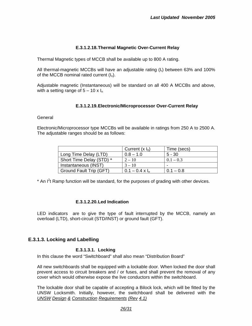
E.3.1.2.19. Electronic/Microprocessor Over-Current Relay General Electronic/Microprocessor type MCCBs will be available in ratings from 250 A to 2500 A. The adjustable ranges should be as follows:
Current (x I0) Time (secs) Long Time Delay (LTD) 0.8 – 1.0 5 - 30 Short Time Delay (STD) * 2 – 10 0.1 – 0.3 Instantaneous (INST) 3 – 10 - Ground Fault Trip (GFT) 0.1 – 0.4 x In 0.1 – 0.8
* An I2t Ramp function will be standard, for the purposes of grading with other devices.
E.3.1.2.20. Led Indication LED indicators are to give the type of fault interrupted by the MCCB, namely an overload (LTD), short-circuit (STD/INST) or ground fault (GFT).
E.3.1.3. Locking and Labelling
E.3.1.3.1. Locking
UNSW Design & Construction Requirements (Rev 4.1)
In this clause the word “Switchboard” shall also mean “Distribution Board” All new switchboards shall be equipped with a lockable door. When locked the door shall prevent access to circuit breakers and / or fuses, and shall prevent the removal of any cover which would otherwise expose the live conductors within the switchboard. The lockable door shall be capable of accepting a Bilock lock, which will be fitted by the UNSW Locksmith. Initially, however, the switchboard shall be delivered with the
26/31

Last Updated November 2005
supplier’s lock and the UNSW Locksmith will subsequently change this lock to the Bilock lock.
The following locking mechanisms are suitable for conversion to the Bilock system:
Standard Lockwood 100 Nightlatch with 60mm Backset and 32mm hole in door
Standard “Double D” hole for a L&F cam lock 19.5mm diameter (Various backsets are available, approx 40mm cam preferred.
Standard cut out for L&F padlockable L-handle to accept padlock.
Abus hasp & staple part no 110/155 to accept a padlock Where a contractor is required to work on an existing switchboard which has been fitted with a Bilock lock, the contractor will be required to apply to the Zone Manager for a key. In these circumstances the contractor may be required to sign an undertaking to return the key by a specified date or to meet the cost of re keying should the key be lost or stolen. Other conditions may be imposed in the undertaking depending on the circumstances.
E.3.1.3.2. Labelling In this clause the word “Switchboard” shall also mean “Distribution Board” A labelling system has been adopted for the campus to meet the following objectives:
To have a uniform switchboards Labelling System across the campus.
To uniquely identify each switchboard.
To identify the location of the switchboard.
To be adaptable to change of location name (i.e. room number)
E.3.1.3.3. Locations of the Labels
UNSW Design & Construction Requirements (Rev 4.1)
The Switchboard label wording will appear in the following places:
On the door of the cupboard, or the door of the switchboard if not mounted in a cupboard.
On the switchboard circuit schedule.
In all other references to the switchboard.
On the door of the room containing the switchboard. This will be determined by UNSW on a case by case basis.
On the door of the room leading to the room containing the switchboard. This will be determined by UNSW on a case by case basis.
27/31
Last Updated November 2005
On the Electrical Fixtures circuit labels (but without the building reference number, see later) which are affixed either to each fixture or in the vicinity thereof. The exception to this is where the switchboard and fixture are in different buildings, in which case the building reference number shall be included.
E.3.1.3.4. Label Elements The switchboard labels shall be of the following format and by way of example the label shall contain the following elements
A particular label is “D26 DB-G.01 (G21)” The elements of this label are as follows:
“D26” – Building reference number
“DB” – Distribution board. Other possibilities are “DBR” – Riser board, “MSB” – Main Switchboard, “MCC” – Mechanical Services Board
“G” – Location of the board is on Ground level. Other possibilities are “LG” – Lower ground, “01” Level 1, “02” – Level 2 etc.
“01” – A sequential number for that type of board starting with 01.
“(G21)” – Room number of the room in which the board is located All numbers less that 10 shall have a leading zero.
E.3.1.3.5. Electrical Fixtures Circuit Labelling The fixtures circuit labelling shall follow the main number with an end qualifier denoting the circuit breaker number. The building grid reference is not included unless the switchboard and fixture are in different buildings, in which case the building reference number shall be included. Therefore the circuits connected to circuit breakers 1,2,3, and 4 etc. in the distribution board “D26 DB-G.01 (G21)” will carry the following labels: DB-G.01 CB01 DB-G.01 CB02 DB-G.01 CB03 DB-G.01 CB04 Etc.
In the case of light fittings controlled by a wall switch, it shall be sufficient to label the wall switch rather than each light fitting.
UNSW
28/31
Design & Construction Requirements (Rev 4.1)
Last Updated November 2005
E.3.1.4. General Purpose Outlets
E.3.1.4.1. Types Of Outlet Generally power outlets will fall within the following four categories: 10 Amps Single Phase Outlets for connection of general electrical equipment to which any interruption or any interference of the supply will not create a loss of data information or damage to the equipment such as photocopy machines, desk-lamps, general laboratory equipment. 10 Amps Single Phase Outlets for the connection of electrical equipment to which any interruption or any interference of the supply will create a gloss of data information and/or damage to equipment. Examples include computer equipment, server high tech monitoring, and laboratory equipment. 10/15 Amps Single Phase Outlets for the connection of electrical equipment powered by electric motors. Examples include vacuum cleaners and other cleaning equipment. 15/20 Amps Three Phase Outlets For the connection of industrial electrical equipment. For example workshop machinery. Power outlet circuits in any design for new buildings or upgrading of existing facilities are to reflect the above requirements.
E.3.1.4.2. General Purpose Outlets Power Outlets are to be flush combination type, 10A, Single pole switch 3 flat pin receptacle unless specified otherwise. The General Purpose Outlets shall comply with the following standard: AS 1428 Design for Access and Mobility The height of the GPO above floor level shall be 1000 mm nominally The layout drawings shall indicate clearly the purpose and colour of the outlets Outlets shall be impact resistant plastic mouldings unless otherwise specified. Flush plates shall be coloured as follows: (To be noted: Painted plates are not acceptable) WHITE for outlets where electrical equipment for general purposes any interruption or any interference of the supply will not create a loss of information or damage to the equipment. (e.g. photocopy machines, desk-lamps and general laboratory equipment) RED for outlets where the connection of electrical equipment to which any interruption or any interference of the supply will create a loss of information and some damage to the equipment. (e.g. computers)
UNSW
29/31
Design & Construction Requirements (Rev 4.1)

Last Updated November 2005
BLUE for cleaning equipment Colour for any 3 Phase outlets is not critical. Mounting height of general-purpose outlets shall be determined in relation to the type, application and usage. Any weatherproof type outlets shall be heavy duty, high impact resistant polycarbonate or metal-clad construction with degree of protection IP 56. Different types of GPO's shall not be ganged under a common flush plate.
E.3.1.4.3. Accessories Accessories shall conform to the following Standards:
Generally: to AS 3000.
Plugs and Socket outlets: to AS 3112.
Socket outlet: to AS 3133.
E.3.1.4.4. Mounting Arrangements The outlet shall always be mounted with the earth pin at the 6 o'clock position.
E.3.1.4.5. Labels, Signs And Notices Unless otherwise stated by the FM Engineering Project Officer, the construction and application of labels, signs and notices shall be as follows: Multi-layered plastic laminates with the core a contrasting colour to the faces; lettering shall be engraved to reveal the contrasting coloured core; edges shall be bevelled. Use for interior or internal applications within office and teaching areas. Labelling on final subcircuits may be of durable stick on type affixed to either the fixture or in the immediate vicinity of the fixture. Fibreglass or rigid vinyl products with embedded legends or graphics and resistant to abrasion or impact, corners shall be rounded edges smoothed and with reinforced fixing holes. Use for safety signs for the laboratory. Brass or bronze plates with engraved painted filled lettering. Use in exterior applications.
E.3.1.4.6. Distribution Boards
UNSW
30/31
Design & Construction Requirements (Rev 4.1)

Last Updated November 2005
All circuit breakers protecting “Blue (Cleaning) GPO” circuits shall have Earth Leakage Protection. Residual Current Protection shall be provided as follows: All circuit breakers protecting “Blue” cleaning GPO’s All circuit breakers protecting “White” GPO’s in laboratories and workshop areas All circuit breakers protecting any outlets which are located in wet areas All circuit breakers connecting sensitive equipment shall be equipped with surge diverter protection. The designer shall coordinate with UNSW to asses if any surge diverter protection is required. Dedicated circuits shall be used for each different types of GPO. Connection of dissimilar types of GPO to the same circuit shall not be allowed. Where possible circuit breakers protecting “Red GPO” circuits shall be positioned at the bottom end of the Distribution board. Where a new Distribution Board is installed for connection of new power outlet circuits, a space of 150mm shall be provided between “White GPO” circuits and “Red GPO” circuits.
E.3.1.5. Testing and Commissioning The electrical installation shall be fully tested
UNSW
31/31
Design & Construction Requirements (Rev 4.1)


![3.1 - Electrical System, Instruments [OCR]](https://img.pdfslide.us/doc/110x75/577cc3b21a28aba71196e387/31-electrical-system-instruments-ocr.jpg)