Embed Size (px)
Citation preview
A2P/N 9021-60764:A2
Document 9021-6076403/23/2016 Rev:
E3 Series® and S3 Series
Building Blocks Reference Guide
Fire Alarm & Emergency Communication System LimitationsWhile a life safety system may lower insurance rates, it is not a substitute for life and property insurance!An automatic fire alarm system—typically made up of smoke detectors, heat detectors, manual pull stations, audible warning devices, and a fire alarm control panel (FACP) with remote notifi-cation capability—can provide early warning of a developing fire. Such a system, however, does not assure protection against property damage or loss of life resulting from a fire.
An emergency communication system—typically made up of an automatic fire alarm system (as described above) and a life safety communication system that may include an autonomous control unit (ACU), local operating console (LOC), voice commu-nication, and other various interoperable communication meth-ods—can broadcast a mass notification message. Such a system, however, does not assure protection against property damage or loss of life resulting from a fire or life safety event.
The Manufacturer recommends that smoke and/or heat detectors be located throughout a protected premises following the recommendations of the current edition of the National Fire Protection Association Standard 72 (NFPA 72), manufacturer's recommendations, State and local codes, and the recommendations contained in the Guide for Proper Use of System Smoke Detectors, which is made available at no charge to all installing dealers. This document can be found at http://www.systemsensor.com/appguides/. A study by the Federal Emergency Management Agency (an agency of the United States government) indicated that smoke detectors may not go off in as many as 35% of all fires. While fire alarm systems are designed to provide early warning against fire, they do not guarantee warning or protection against fire. A fire alarm system may not provide timely or adequate warning, or simply may not function, for a variety of reasons:
Smoke detectors may not sense fire where smoke cannot reach the detectors such as in chimneys, in or behind walls, on roofs, or on the other side of closed doors. Smoke detectors also may not sense a fire on another level or floor of a building. A sec-ond-floor detector, for example, may not sense a first-floor or basement fire.
Particles of combustion or “smoke” from a developing fire may not reach the sensing chambers of smoke detectors because:
• Barriers such as closed or partially closed doors, walls, chim-neys, even wet or humid areas may inhibit particle or smoke flow.
• Smoke particles may become “cold,” stratify, and not reach the ceiling or upper walls where detectors are located.
• Smoke particles may be blown away from detectors by air outlets, such as air conditioning vents.
• Smoke particles may be drawn into air returns before reach-ing the detector.
The amount of “smoke” present may be insufficient to alarm smoke detectors. Smoke detectors are designed to alarm at var-ious levels of smoke density. If such density levels are not cre-ated by a developing fire at the location of detectors, the detectors will not go into alarm.
Smoke detectors, even when working properly, have sensing limitations. Detectors that have photoelectronic sensing cham-bers tend to detect smoldering fires better than flaming fires, which have little visible smoke. Detectors that have ionizing-type sensing chambers tend to detect fast-flaming fires better than smoldering fires. Because fires develop in different ways and are often unpredictable in their growth, neither type of detector is necessarily best and a given type of detector may not provide adequate warning of a fire.
Smoke detectors cannot be expected to provide adequate warn-ing of fires caused by arson, children playing with matches (especially in bedrooms), smoking in bed, and violent explosions
(caused by escaping gas, improper storage of flammable materi-als, etc.).
Heat detectors do not sense particles of combustion and alarm only when heat on their sensors increases at a predetermined rate or reaches a predetermined level. Rate-of-rise heat detec-tors may be subject to reduced sensitivity over time. For this rea-son, the rate-of-rise feature of each detector should be tested at least once per year by a qualified fire protection specialist. Heat detectors are designed to protect property, not life.
IMPORTANT! Smoke detectors must be installed in the same room as the control panel and in rooms used by the system for the connection of alarm transmission wiring, communications, signaling, and/or power. If detectors are not so located, a devel-oping fire may damage the alarm system, compromising its abil-ity to report a fire.
Audible warning devices such as bells, horns, strobes, speakers and displays may not alert people if these devices are located on the other side of closed or partly open doors or are located on another floor of a building. Any warning device may fail to alert people with a disability or those who have recently consumed drugs, alcohol, or medication. Please note that:
• An emergency communication system may take priority over a fire alarm system in the event of a life safety emergency.
• Voice messaging systems must be designed to meet intelligi-bility requirements as defined by NFPA, local codes, and Authorities Having Jurisdiction (AHJ).
• Language and instructional requirements must be clearly dis-seminated on any local displays.
• Strobes can, under certain circumstances, cause seizures in people with conditions such as epilepsy.
• Studies have shown that certain people, even when they hear a fire alarm signal, do not respond to or comprehend the meaning of the signal. Audible devices, such as horns and bells, can have different tonal patterns and frequencies. It is the property owner's responsibility to conduct fire drills and other training exercises to make people aware of fire alarm signals and instruct them on the proper reaction to alarm sig-nals.
• In rare instances, the sounding of a warning device can cause temporary or permanent hearing loss.
A life safety system will not operate without any electrical power. If AC power fails, the system will operate from standby batteries only for a specified time and only if the batteries have been properly maintained and replaced regularly.
Equipment used in the system may not be technically compat-ible with the control panel. It is essential to use only equipment listed for service with your control panel.
Telephone lines needed to transmit alarm signals from a prem-ises to a central monitoring station may be out of service or tem-porarily disabled. For added protection against telephone line failure, backup radio transmission systems are recommended.
The most common cause of life safety system malfunction is inadequate maintenance. To keep the entire life safety system in excellent working order, ongoing maintenance is required per the manufacturer's recommendations, and UL and NFPA standards. At a minimum, the requirements of NFPA 72 shall be followed. Environments with large amounts of dust, dirt, or high air velocity require more frequent maintenance. A maintenance agreement should be arranged through the local manufacturer's representa-tive. Maintenance should be scheduled as required by National and/or local fire codes and should be performed by authorized professional life safety system installers only. Adequate written records of all inspections should be kept.
Limit-D2-2016
2 E3 Series and S3 Series Building Blocks Reference Guide — P/N 9021-60764:A2 03/23/2016
Installation PrecautionsAdherence to the following will aid in problem-free installation with long-term reliability:WARNING - Several different sources of power can be connected to the fire alarm control panel. Disconnect all sources of power before servicing. Control unit and associ-ated equipment may be damaged by removing and/or insert-ing cards, modules, or interconnecting cables while the unit is energized. Do not attempt to install, service, or operate this unit until manuals are read and understood.
CAUTION - System Re-acceptance Test after Software Changes: To ensure proper system operation, this product must be tested in accordance with NFPA 72 after any pro-gramming operation or change in site-specific software. Re-acceptance testing is required after any change, addition or deletion of system components, or after any modification, repair or adjustment to system hardware or wiring. All compo-nents, circuits, system operations, or software functions known to be affected by a change must be 100% tested. In addition, to ensure that other operations are not inadvertently affected, at least 10% of initiating devices that are not directly affected by the change, up to a maximum of 50 devices, must also be tested and proper system operation verified.
This system meets NFPA requirements for operation at 0-49º C/32-120º F and at a relative humidity 93% ± 2% RH (non-condensing) at 32°C ± 2°C (90°F ± 3°F). However, the useful life of the system's standby batteries and the electronic com-ponents may be adversely affected by extreme temperature ranges and humidity. Therefore, it is recommended that this system and its peripherals be installed in an environment with a normal room temperature of 15-27º C/60-80º F.
Verify that wire sizes are adequate for all initiating and indi-cating device loops. Most devices cannot tolerate more than a 10% I.R. drop from the specified device voltage.
Like all solid state electronic devices, this system may operate erratically or can be damaged when subjected to light-ning induced transients. Although no system is completely immune from lightning transients and interference, proper grounding will reduce susceptibility. Overhead or outside aerial wiring is not recommended, due to an increased susceptibility to nearby lightning strikes. Consult with the Technical Ser-vices Department if any problems are anticipated or encoun-tered.
Disconnect AC power and batteries prior to removing or inserting circuit boards. Failure to do so can damage circuits.
Remove all electronic assemblies prior to any drilling, filing, reaming, or punching of the enclosure. When possible, make all cable entries from the sides or rear. Before making modifi-cations, verify that they will not interfere with battery, trans-former, or printed circuit board location.
Do not tighten screw terminals more than 9 in-lbs. Over-tightening may damage threads, resulting in reduced terminal contact pressure and difficulty with screw terminal removal.
This system contains static-sensitive components. Always ground yourself with a proper wrist strap before han-dling any circuits so that static charges are removed from the body. Use static suppressive packaging to protect electronic assemblies removed from the unit.
Follow the instructions in the installation, operating, and pro-gramming manuals. These instructions must be followed to avoid damage to the control panel and associated equipment. FACP operation and reliability depend upon proper installation.
Precau-D1-9-2005
FCC WarningWARNING: This equipment generates, uses, and can radiate radio frequency energy and if not installed and used in accordance with the instruction manual may cause interference to radio communications. It has been tested and found to comply with the limits for class A computing devices pursuant to Subpart B of Part 15 of FCC Rules, which is designed to provide reasonable protection against such interference when devices are operated in a commercial environment. Operation of this equipment in a residential area is likely to cause interfer-ence, in which case the user will be required to correct the interference at his or her own expense.
Canadian Requirements
This digital apparatus does not exceed the Class A limits for radiation noise emissions from digital apparatus set out in the Radio Interference Regulations of the Cana-dian Department of Communications.
Le present appareil numerique n'emet pas de bruits radi-oelectriques depassant les limites applicables aux appa-reils numeriques de la classe A prescrites dans le Reglement sur le brouillage radioelectrique edicte par le ministere des Communications du Canada.
eVance™ is a trademark; and Acclimate®, FocalPoint®, Gamewell-FCI®, FAAST Fire Alarm Aspiration Sensing Technology®, Intelligent FAAST®,SmartScan®, SWIFT®, Velociti®, and E3 Series® are registered trademarks of Honeywell International Inc. Microsoft® and Windows® are registeredtrademarks of the Microsoft Corporation. Chrome™ and Google™ are trademarks of Google Inc.
©2016 by Honeywell International Inc. All rights reserved. Unauthorized use of this document is strictly prohibited.
E3 Series and S3 Series Building Blocks Reference Guide — P/N 9021-60764:A2 03/23/2016 3
Software DownloadsIn order to supply the latest features and functionality in fire alarm and life safety technology to our customers, we make frequent upgrades to the embedded software in our products. To ensure that you are installing and programming the latest features, we strongly recommend that you download the most current version of software for each product prior to commissioning any system. Contact Technical Support with any questions about software and the appropriate version for a specific application.
Documentation FeedbackYour feedback helps us keep our documentation up-to-date and accurate. If you have any comments or suggestions about our online Help or printed manuals, you can email us.
Please include the following information:
•Product name and version number (if applicable)
•Printed manual or online Help
•Topic Title (for online Help)
•Page number (for printed manual)
•Brief description of content you think should be improved or corrected
•Your suggestion for how to correct/improve documentation
Send email messages to:
Please note this email address is for documentation feedback only. If you have any technical issues, please contact Technical Services.
4 E3 Series and S3 Series Building Blocks Reference Guide — P/N 9021-60764:A2 03/23/2016
E3 Series and S3 Series Building Blocks Reference Guide — P/N 9021-60764:A2 03/23/2016 5
Table of Contents
Section 1: Basic E3 Series Remote Configurations ..............................................................61.1: E3 Series Remote Annunciator, E3BB-BAA1 Cabinet Ordering Information .............................................71.2: E3 Series Remote Annunciator, E3BB-BA2 Cabinet Ordering Information ................................................81.3: E3 Series Remote Annunciator, E3BB-FLUSH-LCD Cabinet Ordering Information..................................91.4: E3 Remote Annunciator, E3BB-NGA-FLUSH Cabinet Ordering Information..........................................101.5: E3 Series Remote Annunciator, E3BB-BAA with E3ID2-A Inner Door Cabinet Ordering Information...111.6: E3 Series Remote Annunciator, RAN-7100 Cabinet Ordering Information ...............................................121.7: KDU-Retrofit Cabinet Ordering Information ..............................................................................................13
Section 2: E3/S3 Series FACP Panel Configurations .......................................................... 142.1: E3 Series B-Slim Cabinet Ordering Information.........................................................................................152.2: E3 Series “B” Size Cabinet Ordering Information ......................................................................................162.3: E3 Series “C” Size Cabinet Ordering Information ......................................................................................172.4: E3 Series Fire/Audio “C” Size Cabinet Ordering Information ...................................................................182.5: E3 Series “D” Size Cabinet Ordering Information......................................................................................192.6: S3-Slim Cabinet Ordering Information .......................................................................................................20
Section 3: Basic E3 Series In-Building Mass Notification Cabinet Configurations.......... 213.1: E3 Series ACU “C” Size Cabinet used for Combination Fire/MNS System (NGA Display) Ordering Information .........................................................................................................................................................223.2: E3 Series ACU “D” Size Cabinet used for Combination Fire/MNS System (NGA Display) Ordering Information .........................................................................................................................................................23
Section 4: Basic E3 Series In-Building Mass Notification LOC Configurations ............... 244.1: E3 Series LOC Local Operating Console Ordering Information ................................................................254.2: E3 Series LOC-TEL Local Operating Console Ordering Information........................................................26
Section 5: Basic E3 Series Audio Transponder Cabinet Configurations .......................... 275.1: E3 Series INX CAB-B Cabinet Ordering Information................................................................................285.2: E3 Series INX CAB-C Cabinet Ordering Information................................................................................295.3: E3 Series INX CAB-D Cabinet Ordering Information................................................................................30
Section 6: E3 Series Classic Bulk Audio Cabinet Configurations ..................................... 316.1: E3 Series Classic, SBB-C4 Cabinet Ordering Information .........................................................................326.2: E3 Series Classic SBB-D4 Ordering Information .......................................................................................33
Section 7: Retrofit Kit Cabinets .............................................................................................347.1: IF600-Retrofit Backbox Ordering Information ...........................................................................................357.2: 600XL Retrofit Backbox Ordering Information..........................................................................................367.3: 7200 Retrofit Kit “B” Size Backbox Ordering Information ........................................................................377.4: 7200 Retrofit Kit “C” Size Backbox Ordering Information ........................................................................38
Basic E3 Series Remote Configurations
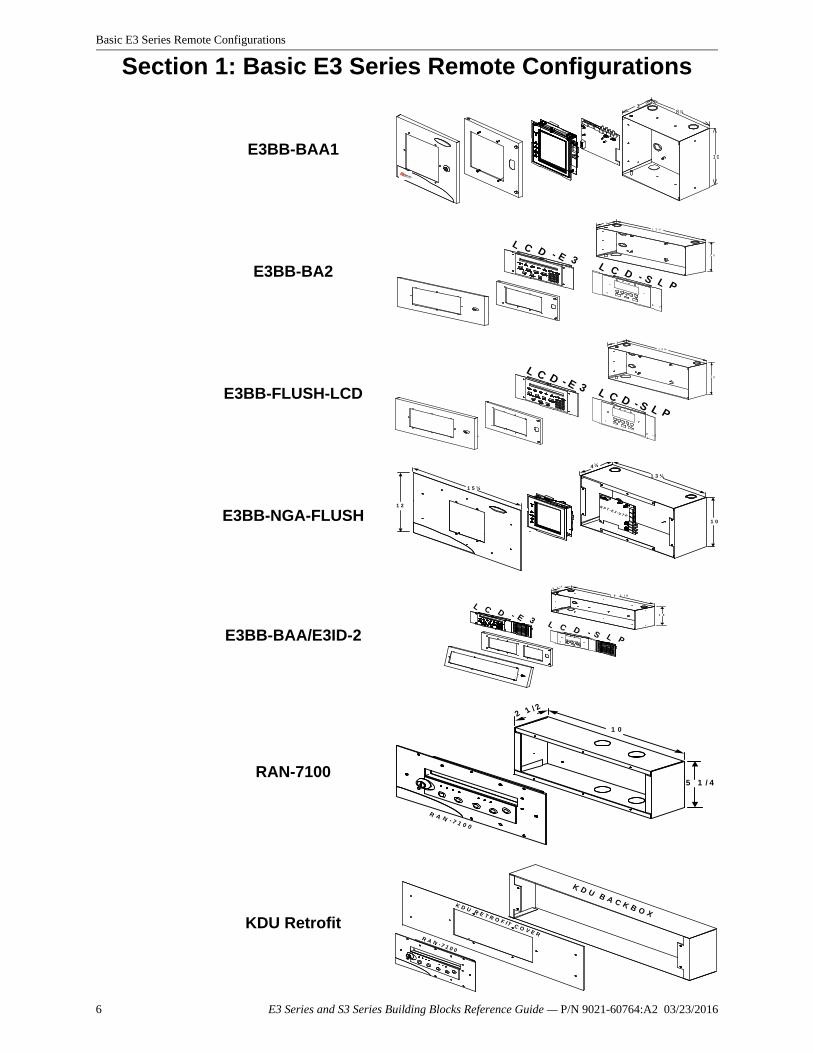
Section 1: Basic E3 Series Remote Configurations
E3BB-BAA1
E3BB-BA2
E3BB-FLUSH-LCD
E3BB-NGA-FLUSH
E3BB-BAA/E3ID-2
RAN-7100
KDU Retrofit
38 ¾
1 0
3
1 0
1 3 ¼
L C D - E 3L C D - S L P
3
1 0
1 3 ¼
L C D - E 3 L C D - S L P
1 0
1 3 ¼
4 ½
1 5 ¼
1 2 R P T - E 3 - U T P
L C D - S L P
L C D - E 31 0
1 9 1 / 4
4 1 / 2
1 0
R A N - 7 1 0 0
5 1 / 4
2 1 / 2
K D U B A C K B O XK D U R E T R O F IT C O V E R
R A N - 7 1 0 0
6 E3 Series and S3 Series Building Blocks Reference Guide — P/N 9021-60764:A2 03/23/2016
E3 Series Remote Annunciator, E3BB-BAA1 Cabinet Ordering Information Basic E3 Series Remote Configurations
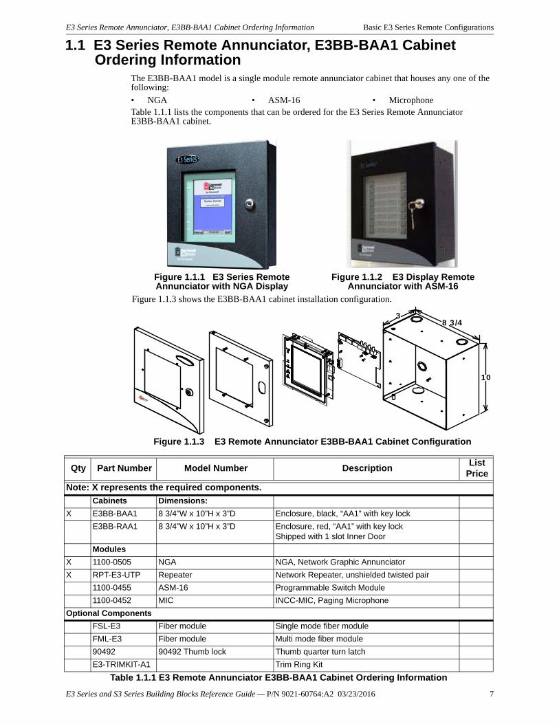
1.1 E3 Series Remote Annunciator, E3BB-BAA1 Cabinet Ordering Information
The E3BB-BAA1 model is a single module remote annunciator cabinet that houses any one of the following:
Table 1.1.1 lists the components that can be ordered for the E3 Series Remote Annunciator E3BB-BAA1 cabinet.
• NGA • ASM-16 • Microphone
Figure 1.1.1 E3 Series Remote Annunciator with NGA Display
Figure 1.1.2 E3 Display Remote Annunciator with ASM-16
Figure 1.1.3 shows the E3BB-BAA1 cabinet installation configuration.
Figure 1.1.3 E3 Remote Annunciator E3BB-BAA1 Cabinet Configuration
3
10
8 3/4
Qty Part Number Model Number DescriptionList
Price
Note: X represents the required components.
Cabinets Dimensions:
X E3BB-BAA1 8 3/4”W x 10”H x 3”D Enclosure, black, “AA1” with key lock
E3BB-RAA1 8 3/4”W x 10”H x 3”D Enclosure, red, “AA1” with key lockShipped with 1 slot Inner Door
Modules
X 1100-0505 NGA NGA, Network Graphic Annunciator
X RPT-E3-UTP Repeater Network Repeater, unshielded twisted pair
1100-0455 ASM-16 Programmable Switch Module
1100-0452 MIC INCC-MIC, Paging Microphone
Optional Components
FSL-E3 Fiber module Single mode fiber module
FML-E3 Fiber module Multi mode fiber module
90492 90492 Thumb lock Thumb quarter turn latch
E3-TRIMKIT-A1 Trim Ring Kit
Table 1.1.1 E3 Remote Annunciator E3BB-BAA1 Cabinet Ordering Information
E3 Series and S3 Series Building Blocks Reference Guide — P/N 9021-60764:A2 03/23/2016 7
Basic E3 Series Remote Configurations E3 Series Remote Annunciator, E3BB-BA2 Cabinet Ordering Information
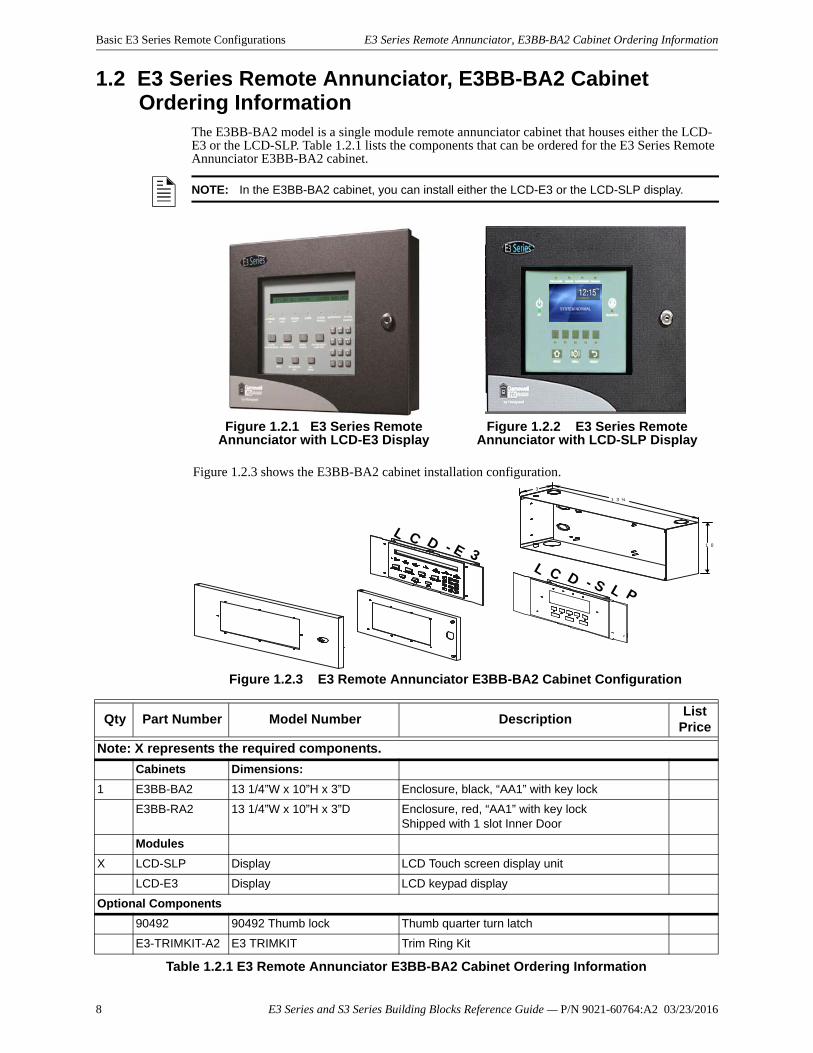
1.2 E3 Series Remote Annunciator, E3BB-BA2 Cabinet Ordering Information
The E3BB-BA2 model is a single module remote annunciator cabinet that houses either the LCD-E3 or the LCD-SLP. Table 1.2.1 lists the components that can be ordered for the E3 Series Remote Annunciator E3BB-BA2 cabinet.
NOTE: In the E3BB-BA2 cabinet, you can install either the LCD-E3 or the LCD-SLP display.
Figure 1.2.1 E3 Series Remote Annunciator with LCD-E3 Display
Figure 1.2.2 E3 Series Remote Annunciator with LCD-SLP Display
Figure 1.2.3 shows the E3BB-BA2 cabinet installation configuration.
Figure 1.2.3 E3 Remote Annunciator E3BB-BA2 Cabinet Configuration
3
1 0
1 3 ¼
L C D - E 3L C D - S L P
Qty Part Number Model Number DescriptionList
Price
Note: X represents the required components.
Cabinets Dimensions:
1 E3BB-BA2 13 1/4”W x 10”H x 3”D Enclosure, black, “AA1” with key lock
E3BB-RA2 13 1/4”W x 10”H x 3”D Enclosure, red, “AA1” with key lockShipped with 1 slot Inner Door
Modules
X LCD-SLP Display LCD Touch screen display unit
LCD-E3 Display LCD keypad display
Optional Components
90492 90492 Thumb lock Thumb quarter turn latch
E3-TRIMKIT-A2 E3 TRIMKIT Trim Ring Kit
Table 1.2.1 E3 Remote Annunciator E3BB-BA2 Cabinet Ordering Information
8 E3 Series and S3 Series Building Blocks Reference Guide — P/N 9021-60764:A2 03/23/2016
E3 Series Remote Annunciator, E3BB-FLUSH-LCD Cabinet Ordering Information Basic E3 Series Remote Configurations
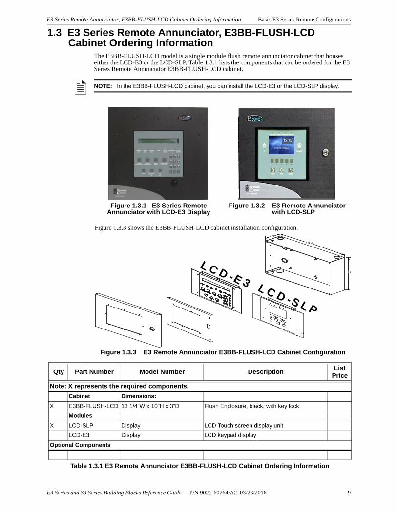
1.3 E3 Series Remote Annunciator, E3BB-FLUSH-LCD Cabinet Ordering Information
The E3BB-FLUSH-LCD model is a single module flush remote annunciator cabinet that houses either the LCD-E3 or the LCD-SLP. Table 1.3.1 lists the components that can be ordered for the E3 Series Remote Annunciator E3BB-FLUSH-LCD cabinet.
NOTE: In the E3BB-FLUSH-LCD cabinet, you can install the LCD-E3 or the LCD-SLP display.
Figure 1.3.1 E3 Series Remote Annunciator with LCD-E3 Display
Figure 1.3.2 E3 Remote Annunciator with LCD-SLP
Figure 1.3.3 shows the E3BB-FLUSH-LCD cabinet installation configuration.
Figure 1.3.3 E3 Remote Annunciator E3BB-FLUSH-LCD Cabinet Configuration
3
1 0
1 3 ¼
L C D -E 3 L C D -S L P
Qty Part Number Model Number DescriptionList
Price
Note: X represents the required components.
Cabinet Dimensions:
X E3BB-FLUSH-LCD 13 1/4”W x 10”H x 3”D Flush Enclosure, black, with key lock
Modules
X LCD-SLP Display LCD Touch screen display unit
LCD-E3 Display LCD keypad display
Optional Components
Table 1.3.1 E3 Remote Annunciator E3BB-FLUSH-LCD Cabinet Ordering Information
E3 Series and S3 Series Building Blocks Reference Guide — P/N 9021-60764:A2 03/23/2016 9
Basic E3 Series Remote Configurations E3 Remote Annunciator, E3BB-NGA-FLUSH Cabinet Ordering Information
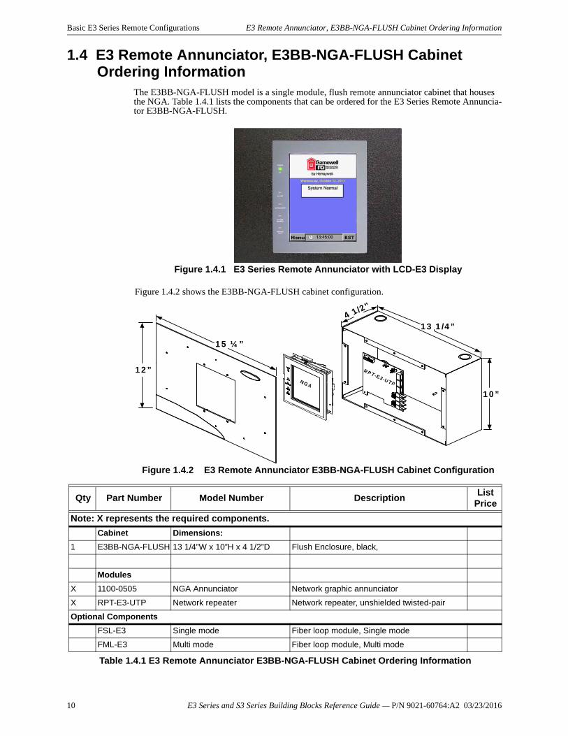
1.4 E3 Remote Annunciator, E3BB-NGA-FLUSH Cabinet Ordering Information
The E3BB-NGA-FLUSH model is a single module, flush remote annunciator cabinet that houses the NGA. Table 1.4.1 lists the components that can be ordered for the E3 Series Remote Annuncia-tor E3BB-NGA-FLUSH.
Figure 1.4.1 E3 Series Remote Annunciator with LCD-E3 Display
Figure 1.4.2 shows the E3BB-NGA-FLUSH cabinet configuration.
Figure 1.4.2 E3 Remote Annunciator E3BB-NGA-FLUSH Cabinet Configuration
R P T-E 3 -U TP
1 5 ¼ ”
1 2 ”
1 0 ”
1 3 1 /4 ”4 1 /2 ”
N G A
Qty Part Number Model Number DescriptionList
Price
Note: X represents the required components.
Cabinet Dimensions:
1 E3BB-NGA-FLUSH 13 1/4”W x 10”H x 4 1/2”D Flush Enclosure, black,
Modules
X 1100-0505 NGA Annunciator Network graphic annunciator
X RPT-E3-UTP Network repeater Network repeater, unshielded twisted-pair
Optional Components
FSL-E3 Single mode Fiber loop module, Single mode
FML-E3 Multi mode Fiber loop module, Multi mode
Table 1.4.1 E3 Remote Annunciator E3BB-NGA-FLUSH Cabinet Ordering Information
10 E3 Series and S3 Series Building Blocks Reference Guide — P/N 9021-60764:A2 03/23/2016
E3 Series Remote Annunciator, E3BB-BAA with E3ID2-A Inner Door Cabinet Ordering Information Basic E3 Series Remote
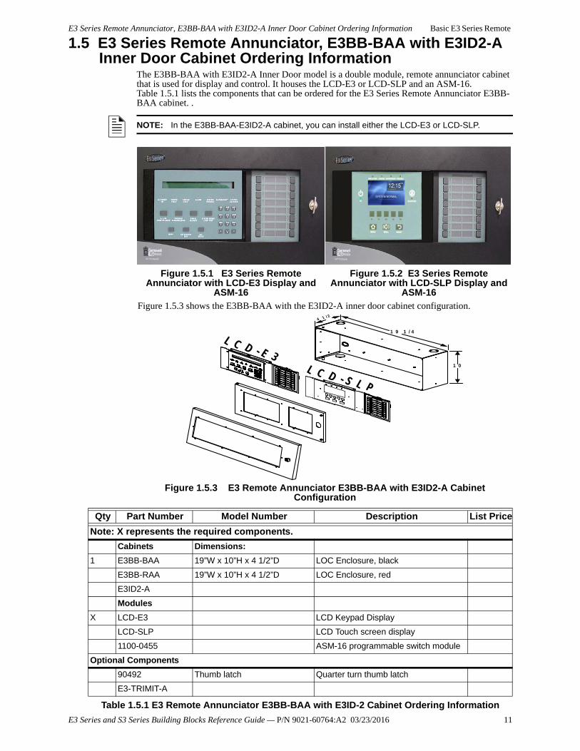
1.5 E3 Series Remote Annunciator, E3BB-BAA with E3ID2-A Inner Door Cabinet Ordering Information
The E3BB-BAA with E3ID2-A Inner Door model is a double module, remote annunciator cabinet that is used for display and control. It houses the LCD-E3 or LCD-SLP and an ASM-16. Table 1.5.1 lists the components that can be ordered for the E3 Series Remote Annunciator E3BB-BAA cabinet. .
NOTE: In the E3BB-BAA-E3ID2-A cabinet, you can install either the LCD-E3 or LCD-SLP.
Figure 1.5.1 E3 Series Remote Annunciator with LCD-E3 Display and
ASM-16
Figure 1.5.2 E3 Series Remote Annunciator with LCD-SLP Display and
ASM-16
Figure 1.5.3 shows the E3BB-BAA with the E3ID2-A inner door cabinet configuration.
Figure 1.5.3 E3 Remote Annunciator E3BB-BAA with E3ID2-A Cabinet Configuration
1 0
1 9 1 / 4
4 1 / 2
L C D - S L P
L C D - E 3
Qty Part Number Model Number Description List Price
Note: X represents the required components.
Cabinets Dimensions:
1 E3BB-BAA 19”W x 10”H x 4 1/2”D LOC Enclosure, black
E3BB-RAA 19”W x 10”H x 4 1/2”D LOC Enclosure, red
E3ID2-A
Modules
X LCD-E3 LCD Keypad Display
LCD-SLP LCD Touch screen display
1100-0455 ASM-16 programmable switch module
Optional Components
90492 Thumb latch Quarter turn thumb latch
E3-TRIMIT-A
Table 1.5.1 E3 Remote Annunciator E3BB-BAA with E3ID-2 Cabinet Ordering Information
E3 Series and S3 Series Building Blocks Reference Guide — P/N 9021-60764:A2 03/23/2016 11
Basic E3 Series Remote Configurations E3 Series Remote Annunciator, RAN-7100 Cabinet Ordering Information
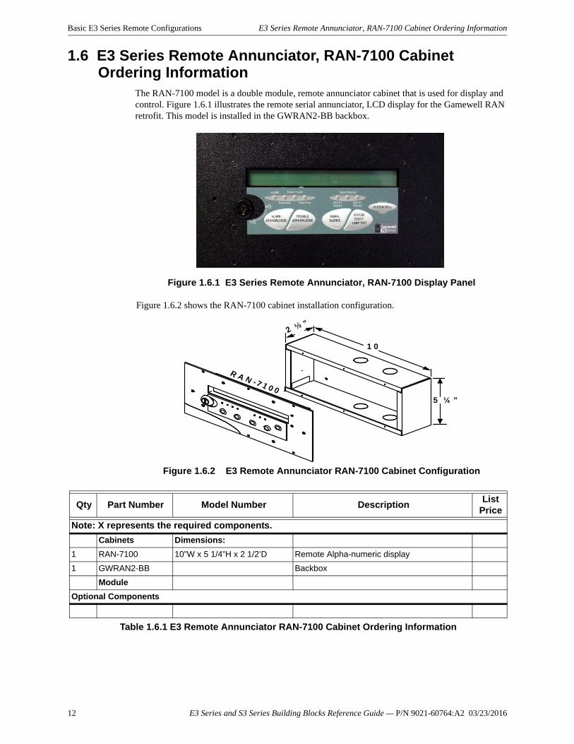
1.6 E3 Series Remote Annunciator, RAN-7100 Cabinet Ordering Information
The RAN-7100 model is a double module, remote annunciator cabinet that is used for display and control. Figure 1.6.1 illustrates the remote serial annunciator, LCD display for the Gamewell RAN retrofit. This model is installed in the GWRAN2-BB backbox.
Figure 1.6.1 E3 Series Remote Annunciator, RAN-7100 Display Panel
Figure 1.6.2 shows the RAN-7100 cabinet installation configuration.
Figure 1.6.2 E3 Remote Annunciator RAN-7100 Cabinet Configuration
1 0
5 ¼ ”
R A N - 7 1 0 0
2 ½ ”
Qty Part Number Model Number DescriptionList
Price
Note: X represents the required components.
Cabinets Dimensions:
1 RAN-7100 10”W x 5 1/4”H x 2 1/2’D Remote Alpha-numeric display
1 GWRAN2-BB Backbox
Module
Optional Components
Table 1.6.1 E3 Remote Annunciator RAN-7100 Cabinet Ordering Information
12 E3 Series and S3 Series Building Blocks Reference Guide — P/N 9021-60764:A2 03/23/2016
KDU-Retrofit Cabinet Ordering Information Basic E3 Series Remote Configurations
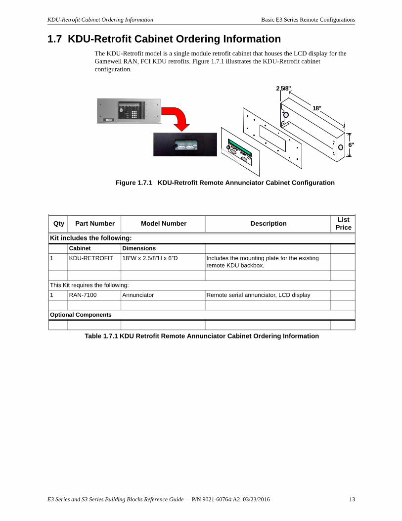
1.7 KDU-Retrofit Cabinet Ordering InformationThe KDU-Retrofit model is a single module retrofit cabinet that houses the LCD display for the Gamewell RAN, FCI KDU retrofits. Figure 1.7.1 illustrates the KDU-Retrofit cabinet configuration.
Figure 1.7.1 KDU-Retrofit Remote Annunciator Cabinet Configuration
2 5/8"
18"
6"
Qty Part Number Model Number DescriptionList
Price
Kit includes the following:
Cabinet Dimensions
1 KDU-RETROFIT 18”W x 2.5/8”H x 6”D Includes the mounting plate for the existing remote KDU backbox.
This Kit requires the following:
1 RAN-7100 Annunciator Remote serial annunciator, LCD display
Optional Components
Table 1.7.1 KDU Retrofit Remote Annunciator Cabinet Ordering Information
E3 Series and S3 Series Building Blocks Reference Guide — P/N 9021-60764:A2 03/23/2016 13
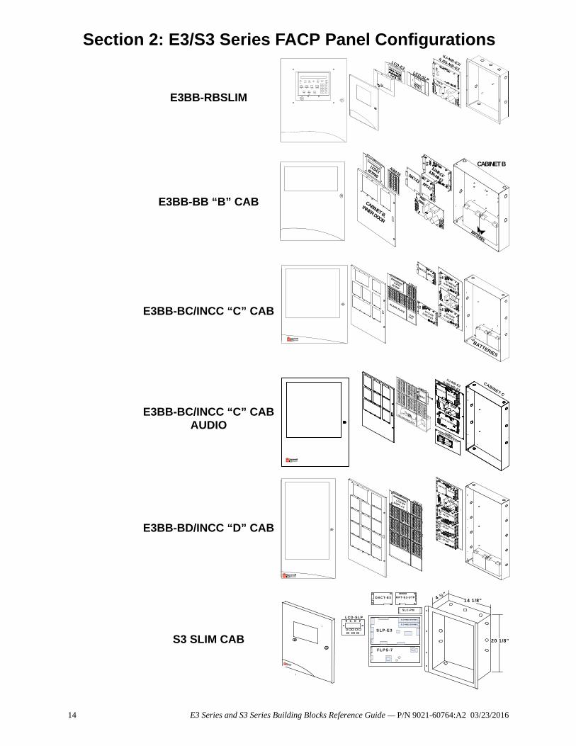
Section 2: E3/S3 Series FACP Panel Configurations
E3BB-RBSLIM
E3BB-BB “B” CAB
E3BB-BC/INCC “C” CAB
E3BB-BC/INCC “C” CABAUDIO
E3BB-BD/INCC “D” CAB
S3 SLIM CAB
-
AC POWE
RON
POWER
FAULT
GROUND
FAULT
ALARM
SYSTEM
TROUBLE
SUPERVISORY
SYSTEM
SILENCED
ALARMACKNOWLED
GE
TROUBLEACKNOWLED
GESIGNALSILENCE
SYSTEM RESET/
LAMP TEST
MENU
BACKSPACE/
EDIT
OK/ENTER
LCD-E3LCD-SLP
ILI-MB-E3/
ILI95-MB-E3
PM-9/PM-9G
CABINET BASM-16 DACT-E3
RPT-E3
PM-9/PM-9GCABINET B,
INNER DOOR
LCD-E3KEYPAD
ILI-MB-E3/ILI95-MB-E3
BATTERIES
LCD-E3KEYPAD
DACT-E3RPT-E3
BLANK PLATEBLANK PLATE
ASM-16
ILI-S-E3/ILI95-S-E3
ILI-MB-E3/
ILI95-MB-E3
ILI-S-E3/ILI95-S-E3
PM-9/PM-9G
BATTERIES
-
NGA
CABINET C
TELEPHONE BOX
INI-VG SERIES
CABINET C
AM-50 EXTENDER PLATEAM-50SERIES
ILI-MB-E3ILI95-MB-E3
PM-9/PM-9G
DACT-E3RPT-E3
-
- -
-
LCD-E3DISPLAY
IL I-S-E3/ILI95-S-E3
OR ANX
ILI-S-E3/ILI95-S-E3
OR ANX
ILI-S -E3/ILI95-S -E3
OR ANX
PM-9/PM-9G
RPT-E3
D ACT-E3
ASM-16
DAC T-E3 R PT-E 3-U TP 4 ½”
14 1/8"
20 1/8"
LCD-SLP
SLP-E3
SLC -PM /SL C95-PM #1
SLC -PM /SL C95-PM #2
FLPS-7
S LC-P M
14 E3 Series and S3 Series Building Blocks Reference Guide — P/N 9021-60764:A2 03/23/2016
E3 Series B-Slim Cabinet Ordering Information E3/S3 Series FACP Panel Configurations
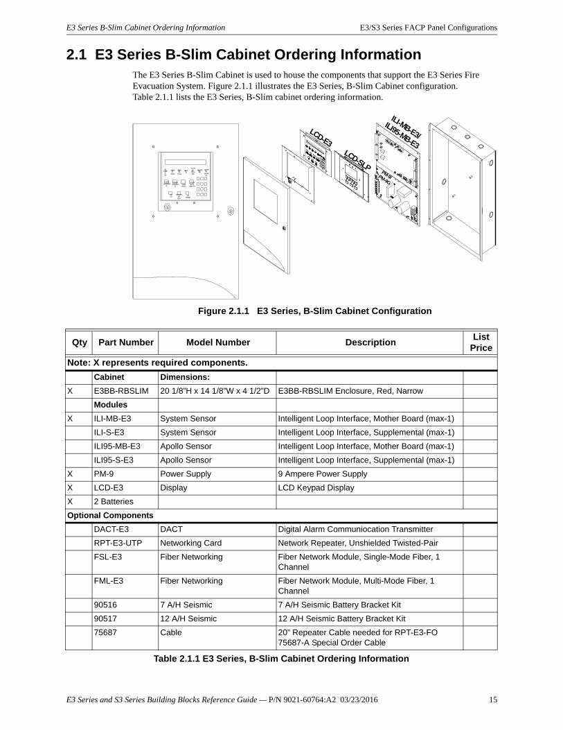
2.1 E3 Series B-Slim Cabinet Ordering InformationThe E3 Series B-Slim Cabinet is used to house the components that support the E3 Series Fire Evacuation System. Figure 2.1.1 illustrates the E3 Series, B-Slim Cabinet configuration. Table 2.1.1 lists the E3 Series, B-Slim cabinet ordering information.
Figure 2.1.1 E3 Series, B-Slim Cabinet Configuration
-
AC POWE
RON
POWER
FAULT
GROUND
FAULT
ALARM
SYSTEM
TROUBLE
SUPERVISORY
SYSTEM
SILENCED
ALARMACKNOWLED
GE
TROUBLEACKNOWLED
GESIGNALSILENCE
SYSTEM RESET/
LAMP TEST
MENU
BACKSPACE/EDIT
OK/ENTER
LCD-E3LCD-SLP
ILI-MB-E3/
ILI95-MB-E3
PM-9/PM-9G
Qty Part Number Model Number DescriptionList
Price
Note: X represents required components.
Cabinet Dimensions:
X E3BB-RBSLIM 20 1/8”H x 14 1/8”W x 4 1/2”D E3BB-RBSLIM Enclosure, Red, Narrow
Modules
X ILI-MB-E3 System Sensor Intelligent Loop Interface, Mother Board (max-1)
ILI-S-E3 System Sensor Intelligent Loop Interface, Supplemental (max-1)
ILI95-MB-E3 Apollo Sensor Intelligent Loop Interface, Mother Board (max-1)
ILI95-S-E3 Apollo Sensor Intelligent Loop Interface, Supplemental (max-1)
X PM-9 Power Supply 9 Ampere Power Supply
X LCD-E3 Display LCD Keypad Display
X 2 Batteries
Optional Components
DACT-E3 DACT Digital Alarm Communiocation Transmitter
RPT-E3-UTP Networking Card Network Repeater, Unshielded Twisted-Pair
FSL-E3 Fiber Networking Fiber Network Module, Single-Mode Fiber, 1 Channel
FML-E3 Fiber Networking Fiber Network Module, Multi-Mode Fiber, 1 Channel
90516 7 A/H Seismic 7 A/H Seismic Battery Bracket Kit
90517 12 A/H Seismic 12 A/H Seismic Battery Bracket Kit
75687 Cable 20” Repeater Cable needed for RPT-E3-FO75687-A Special Order Cable
Table 2.1.1 E3 Series, B-Slim Cabinet Ordering Information
E3 Series and S3 Series Building Blocks Reference Guide — P/N 9021-60764:A2 03/23/2016 15
E3/S3 Series FACP Panel Configurations E3 Series “B” Size Cabinet Ordering Information
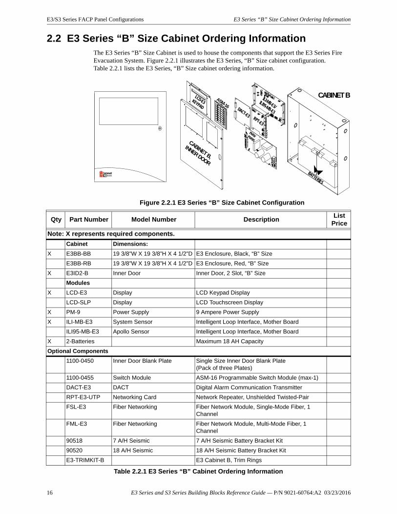
2.2 E3 Series “B” Size Cabinet Ordering InformationThe E3 Series “B” Size Cabinet is used to house the components that support the E3 Series Fire Evacuation System. Figure 2.2.1 illustrates the E3 Series, “B” Size cabinet configuration. Table 2.2.1 lists the E3 Series, “B” Size cabinet ordering information.
Figure 2.2.1 E3 Series “B” Size Cabinet Configuration
CABINET B
BATTERIES
CABINET B,
INNER DOOR
ASM-16
LCD-E3KEYPAD DACT-E3 RPT-E3
PM-9/PM-9G
ILI-MB-E3/ILI95-MB-E3
Qty Part Number Model Number DescriptionList
Price
Note: X represents required components.
Cabinet Dimensions:
X E3BB-BB 19 3/8”W X 19 3/8”H X 4 1/2”D E3 Enclosure, Black, “B” Size
E3BB-RB 19 3/8”W X 19 3/8”H X 4 1/2”D E3 Enclosure, Red, “B” Size
X E3ID2-B Inner Door Inner Door, 2 Slot, “B” Size
Modules
X LCD-E3 Display LCD Keypad Display
LCD-SLP Display LCD Touchscreen Display
X PM-9 Power Supply 9 Ampere Power Supply
X ILI-MB-E3 System Sensor Intelligent Loop Interface, Mother Board
ILI95-MB-E3 Apollo Sensor Intelligent Loop Interface, Mother Board
X 2-Batteries Maximum 18 AH Capacity
Optional Components
1100-0450 Inner Door Blank Plate Single Size Inner Door Blank Plate (Pack of three Plates)
1100-0455 Switch Module ASM-16 Programmable Switch Module (max-1)
DACT-E3 DACT Digital Alarm Communication Transmitter
RPT-E3-UTP Networking Card Network Repeater, Unshielded Twisted-Pair
FSL-E3 Fiber Networking Fiber Network Module, Single-Mode Fiber, 1 Channel
FML-E3 Fiber Networking Fiber Network Module, Multi-Mode Fiber, 1 Channel
90518 7 A/H Seismic 7 A/H Seismic Battery Bracket Kit
90520 18 A/H Seismic 18 A/H Seismic Battery Bracket Kit
E3-TRIMKIT-B E3 Cabinet B, Trim Rings
Table 2.2.1 E3 Series “B” Cabinet Ordering Information
16 E3 Series and S3 Series Building Blocks Reference Guide — P/N 9021-60764:A2 03/23/2016
E3 Series “C” Size Cabinet Ordering Information E3/S3 Series FACP Panel Configurations
E3 Series and S3 Series Building Blocks Reference Guide — P/N 9021-60764:A2 03/23/2016 17
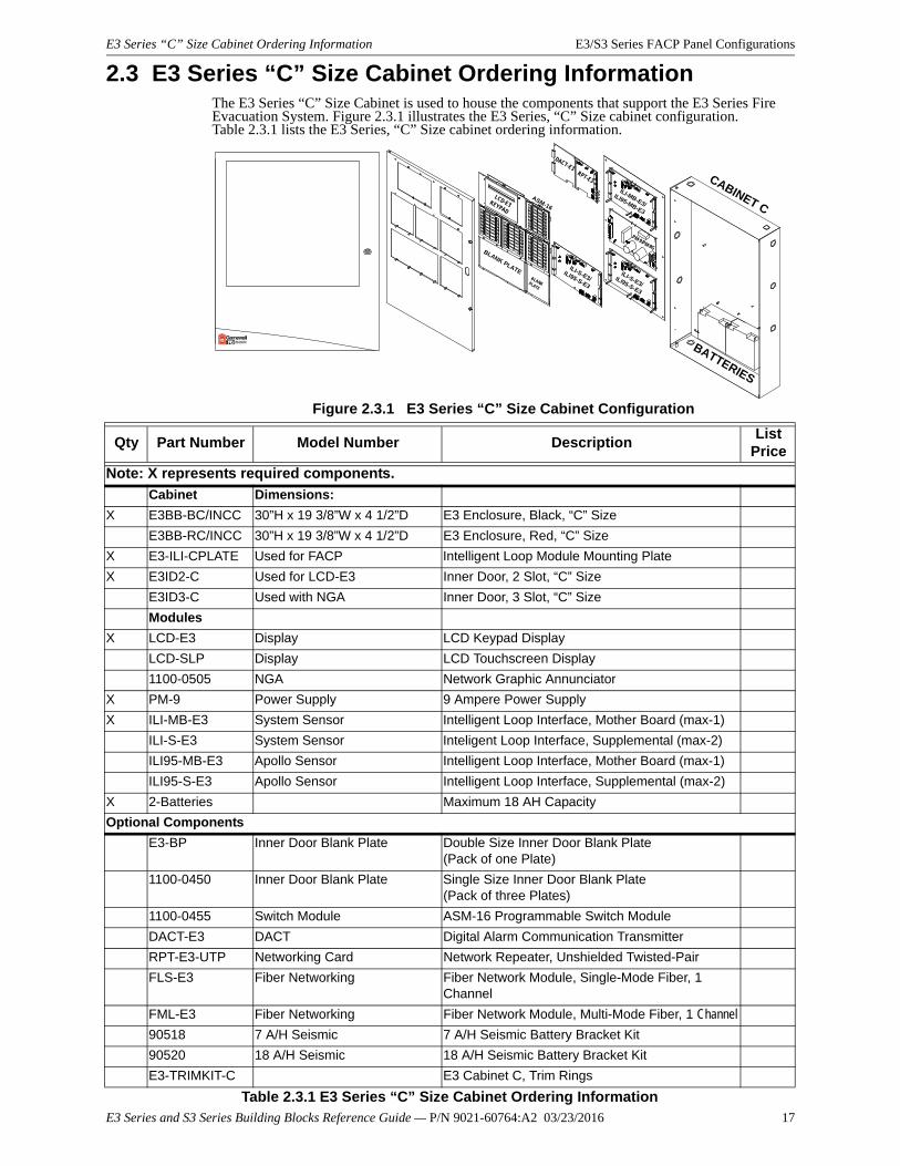
2.3 E3 Series “C” Size Cabinet Ordering InformationThe E3 Series “C” Size Cabinet is used to house the components that support the E3 Series Fire Evacuation System. Figure 2.3.1 illustrates the E3 Series, “C” Size cabinet configuration. Table 2.3.1 lists the E3 Series, “C” Size cabinet ordering information.
Figure 2.3.1 E3 Series “C” Size Cabinet Configuration
ILI-S-E3/ILI95-S-E3
ILI-MB-E3/
ILI95-MB-E3
ILI-S-E3/ILI95-S-E3
PM-9/PM-9G
BATTERIES
LCD-E3KEYPAD
DACT-E3RPT-E3
BLANK PLATEBLANK PLATE
ASM-16
CABINET C
Qty Part Number Model Number DescriptionList
Price
Note: X represents required components.
Cabinet Dimensions:
X E3BB-BC/INCC 30”H x 19 3/8”W x 4 1/2”D E3 Enclosure, Black, “C” Size
E3BB-RC/INCC 30”H x 19 3/8”W x 4 1/2”D E3 Enclosure, Red, “C” Size
X E3-ILI-CPLATE Used for FACP Intelligent Loop Module Mounting Plate
X E3ID2-C Used for LCD-E3 Inner Door, 2 Slot, “C” Size
E3ID3-C Used with NGA Inner Door, 3 Slot, “C” Size
Modules
X LCD-E3 Display LCD Keypad Display
LCD-SLP Display LCD Touchscreen Display
1100-0505 NGA Network Graphic Annunciator
X PM-9 Power Supply 9 Ampere Power Supply
X ILI-MB-E3 System Sensor Intelligent Loop Interface, Mother Board (max-1)
ILI-S-E3 System Sensor Inteligent Loop Interface, Supplemental (max-2)
ILI95-MB-E3 Apollo Sensor Intelligent Loop Interface, Mother Board (max-1)
ILI95-S-E3 Apollo Sensor Intelligent Loop Interface, Supplemental (max-2)
X 2-Batteries Maximum 18 AH Capacity
Optional Components
E3-BP Inner Door Blank Plate Double Size Inner Door Blank Plate (Pack of one Plate)
1100-0450 Inner Door Blank Plate Single Size Inner Door Blank Plate (Pack of three Plates)
1100-0455 Switch Module ASM-16 Programmable Switch Module
DACT-E3 DACT Digital Alarm Communication Transmitter
RPT-E3-UTP Networking Card Network Repeater, Unshielded Twisted-Pair
FLS-E3 Fiber Networking Fiber Network Module, Single-Mode Fiber, 1 Channel
FML-E3 Fiber Networking Fiber Network Module, Multi-Mode Fiber, 1 Channel
90518 7 A/H Seismic 7 A/H Seismic Battery Bracket Kit
90520 18 A/H Seismic 18 A/H Seismic Battery Bracket Kit
E3-TRIMKIT-C E3 Cabinet C, Trim Rings
Table 2.3.1 E3 Series “C” Size Cabinet Ordering Information
E3/S3 Series FACP Panel Configurations E3 Series Fire/Audio “C” Size Cabinet Ordering Information
2.4 E3 Series Fire/Audio “C” Size Cabinet Ordering Information
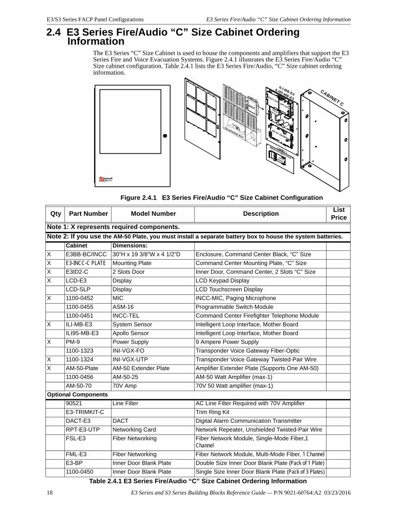
The E3 Series “C” Size Cabinet is used to house the components and amplifiers that support the E3 Series Fire and Voice Evacuation Systems. Figure 2.4.1 illustrates the E3 Series Fire/Audio “C” Size cabinet configuration. Table 2.4.1 lists the E3 Series Fire/Audio, “C” Size cabinet ordering information.
Figure 2.4.1 E3 Series Fire/Audio “C” Size Cabinet Configuration
-
NGA
CABINET C
TELEPHONE BOX
INI-VG SERIES
CABINET C
AM-50 EXTENDER PLATEAM-50SERIES
ILI-MB-E3ILI95-MB-E3
PM-9/PM-9G
DACT-E3RPT-E3
Qty Part Number Model Number DescriptionList
Price
Note 1: X represents required components.
Note 2: If you use the AM-50 Plate, you must install a separate battery box to house the system batteries.
Cabinet Dimensions:
X E3BB-BC/INCC 30”H x 19 3/8”W x 4 1/2”D Enclosure, Command Center Black, “C” Size
X E3-INCC-C PLATE Mounting Plate Command Center Mounting Plate, “C” Size
X E3ID2-C 2 Slots Door Inner Door, Command Center, 2 Slots “C” Size
X LCD-E3 Display LCD Keypad Display
LCD-SLP Display LCD Touchscreen Display
X 1100-0452 MIC INCC-MIC, Paging Microphone
1100-0455 ASM-16 Programmable Switch Module
1100-0451 INCC-TEL Command Center Firefighter Telephone Module
X ILI-MB-E3 System Sensor Intelligent Loop Interface, Mother Board
ILI95-MB-E3 Apollo Sensor Intelligent Loop Interface, Mother Board
X PM-9 Power Supply 9 Ampere Power Supply
1100-1323 INI-VGX-FO Transponder Voice Gateway Fiber-Optic
X 1100-1324 INI-VGX-UTP Transponder Voice Gateway Twisted-Pair Wire
X AM-50-Plate AM-50 Extender Plate Amplifier Extender Plate (Supports One AM-50)
1100-0456 AM-50-25 AM-50 Watt Amplifier (max-1)
AM-50-70 70V Amp 70V 50 Watt amplifier (max-1)
Optional Components
90521 Line Filter AC Line Filter Required with 70V Amplifier
E3-TRIMKIT-C Trim Ring Kit
DACT-E3 DACT Digital Alarm Communication Transmitter
RPT-E3-UTP Networking Card Network Repeater, Unshielded Twisted-Pair Wire
FSL-E3 Fiber Networking Fiber Network Module, Single-Mode Fiber,1 Channel
FML-E3 Fiber Networking Fiber Network Module, Multi-Mode Fiber, 1 Channel
E3-BP Inner Door Blank Plate Double Size Inner Door Blank Plate (Pack of 1 Plate)
1100-0450 Inner Door Blank Plate Single Size Inner Door Blank Plate (Pack of 3 Plates)
Table 2.4.1 E3 Series Fire/Audio “C” Size Cabinet Ordering Information
18 E3 Series and S3 Series Building Blocks Reference Guide — P/N 9021-60764:A2 03/23/2016
E3 Series “D” Size Cabinet Ordering Information E3/S3 Series FACP Panel Configurations
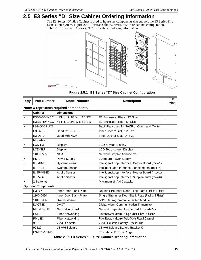
2.5 E3 Series “D” Size Cabinet Ordering InformationThe E3 Series “D” Size Cabinet is used to house the components that support the E3 Series Fire Evacuation System. Figure 2.5.1 illustrates the E3 Series, “D” Size cabinet configuration. Table 2.5.1 lists the E3 Series, “D” Size cabinet ordering information.
Figure 2.5.1 E3 Series “D” Size Cabinet Configuration
DACT-E3RPT-E3
PM-9/PM-9G
ILI-S-E3,ILI95-S-E3SERIESOR ANX
ILI-S-E3,ILI95-S-E3SERIESOR ANX
ILI-S-E3,ILI95-S-E3SERIESOR ANX
LCD-E3DISPLAY
Qty Part Number Model Number DescriptionList
Price
Note: X represents required components.
Cabinet Dimensions:
X E3BB-BD/INCC 41”H x 19 3/8”W x 4 1/2”D E3 Enclosure, Black, “D” Size
E3BB-RD/INCC 41”H x 19 3/8”W x 4 1/2”D E3 Enclosure, Red, “D” Size
X E3-INCC-D PLATE Back Plate used for FACP or Command Center
X E3ID2-D Used for LCD-E3 Inner Door, 2 Slot, “D” Size
E3ID3-D Used with NGA Inner Door, 3 Slot, “D” Size
Modules
X LCD-E3 Display LCD Keypad Display
LCD-SLP Display LCD Touchscreen Display
1100-0505 NGA Network Graphic Annunciator
X PM-9 Power Supply 9 Ampere Power Supply
X ILI-MB-E3 System Sensor Intelligent Loop Interface, Mother Board (max-1)
ILI-S-E3 System Sensor Inteligent Loop Interface, Supplemental (max-6)
ILI95-MB-E3 Apollo Sensor Intelligent Loop Interface, Mother Board (max-1)
ILI95-S-E3 Apollo Sensor Intelligent Loop Interface, Supplemental (max-6)
X 2-Batteries Maximum 18 AH Capacity
Optional Components
E3-BP Inner Door Blank Plate Double Size Inner Door Blank Plate (Pack of 1 Plate)
1100-0450 Inner Door Blank Plate Single Size Inner Door Blank Plate (Pack of 3 Plates)
1100-0455 Switch Module ASM-16 Programmable Switch Module
DACT-E3 DACT Digital Alarm Communication Transmitter
RPT-E3-UTP Networking Card Network Repeater, Unshielded Twisted-Pair
FSL-E3 Fiber Networking Fiber Network Module, Single-Mode Fiber,1 Channel
FML-E3 Fiber Networking Fiber Network Module, Multi-Mode Fiber,1 Channel
90518 7 A/H Seismic 7 A/H Seismic Battery Bracket Kit
90520 18 A/H Seismic 18 A/H Seismic Battery Bracket Kit
E3-TRIMKIT-D E3 Cabinet D, Trim Rings
Table 2.5.1 E3 Series “D” Size Cabinet Ordering Information
E3 Series and S3 Series Building Blocks Reference Guide — P/N 9021-60764:A2 03/23/2016 19
E3/S3 Series FACP Panel Configurations S3-Slim Cabinet Ordering Information
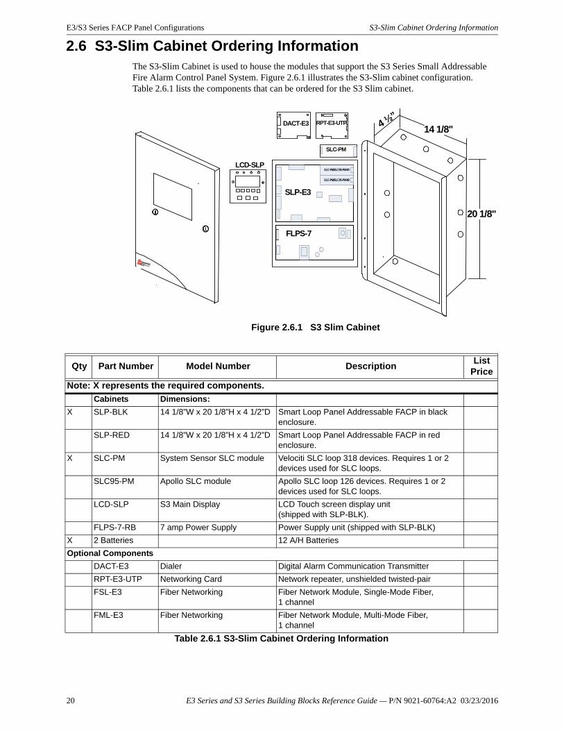
2.6 S3-Slim Cabinet Ordering InformationThe S3-Slim Cabinet is used to house the modules that support the S3 Series Small Addressable Fire Alarm Control Panel System. Figure 2.6.1 illustrates the S3-Slim cabinet configuration. Table 2.6.1 lists the components that can be ordered for the S3 Slim cabinet.
Figure 2.6.1 S3 Slim Cabinet
DACT-E3 RPT-E3-UTP 4 ½”14 1/8"
20 1/8"
LCD-SLP
SLP-E3
SLC-PM/SLC95-PM #1
SLC-PM/SLC95-PM #2
FLPS-7
SLC-PM
Qty Part Number Model Number DescriptionList
Price
Note: X represents the required components.
Cabinets Dimensions:
X SLP-BLK 14 1/8”W x 20 1/8”H x 4 1/2”D Smart Loop Panel Addressable FACP in black enclosure.
SLP-RED 14 1/8”W x 20 1/8”H x 4 1/2”D Smart Loop Panel Addressable FACP in red enclosure.
X SLC-PM System Sensor SLC module Velociti SLC loop 318 devices. Requires 1 or 2 devices used for SLC loops.
SLC95-PM Apollo SLC module Apollo SLC loop 126 devices. Requires 1 or 2 devices used for SLC loops.
LCD-SLP S3 Main Display LCD Touch screen display unit (shipped with SLP-BLK).
FLPS-7-RB 7 amp Power Supply Power Supply unit (shipped with SLP-BLK)
X 2 Batteries 12 A/H Batteries
Optional Components
DACT-E3 Dialer Digital Alarm Communication Transmitter
RPT-E3-UTP Networking Card Network repeater, unshielded twisted-pair
FSL-E3 Fiber Networking Fiber Network Module, Single-Mode Fiber, 1 channel
FML-E3 Fiber Networking Fiber Network Module, Multi-Mode Fiber, 1 channel
Table 2.6.1 S3-Slim Cabinet Ordering Information
20 E3 Series and S3 Series Building Blocks Reference Guide — P/N 9021-60764:A2 03/23/2016
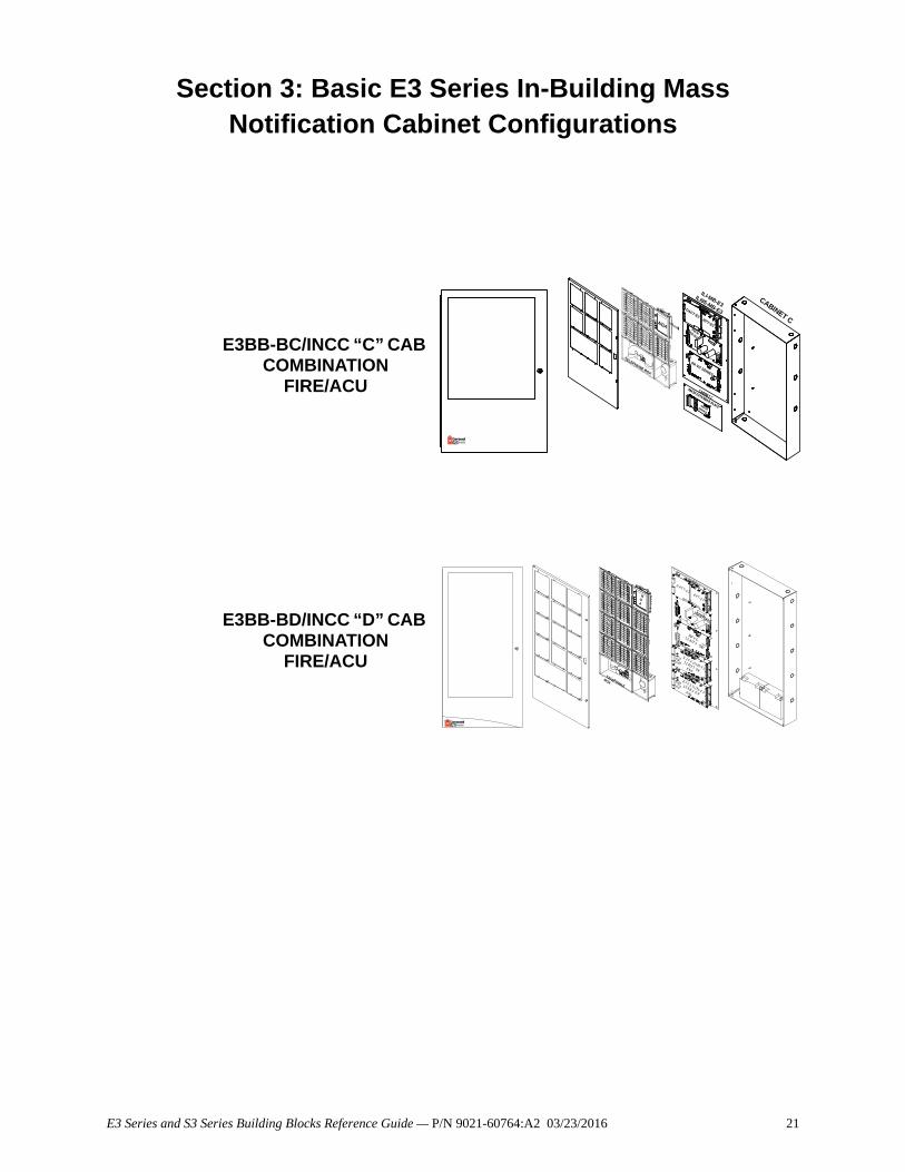
Section 3: Basic E3 Series In-Building Mass Notification Cabinet Configurations
E3BB-BC/INCC “C” CAB COMBINATION
FIRE/ACU
E3BB-BD/INCC “D” CAB COMBINATION
FIRE/ACU
-
NGA
CABINET C
TELEPHONE BOX
INI-VG SERIES
CABINET C
AM-50 EXTENDER PLATEAM-50SERIES
ILI-MB-E3ILI95-MB-E3
PM-9/PM-9G
DACT-E3RPT-E3
TELEPHON E
BOX
NGA
D A CT- E 3RP T- E 3
PM-9/PM-9G
IN I- V GS E RI E S
IL I- E 3, I LI 95- E 3
S E RI E SOR
A N X
IL I- E 3, I LI 95- E 3
S E RIE S O RA NX
E3 Series and S3 Series Building Blocks Reference Guide — P/N 9021-60764:A2 03/23/2016 21
22 E3 Series and S3 Series Building Blocks Reference Guide — P/N 9021-60764:A2 03/23/2016
Basic E3 Series In-Building Mass Notification Cabinet Configurations E3 Series ACU “C” Size Cabinet used for Combination
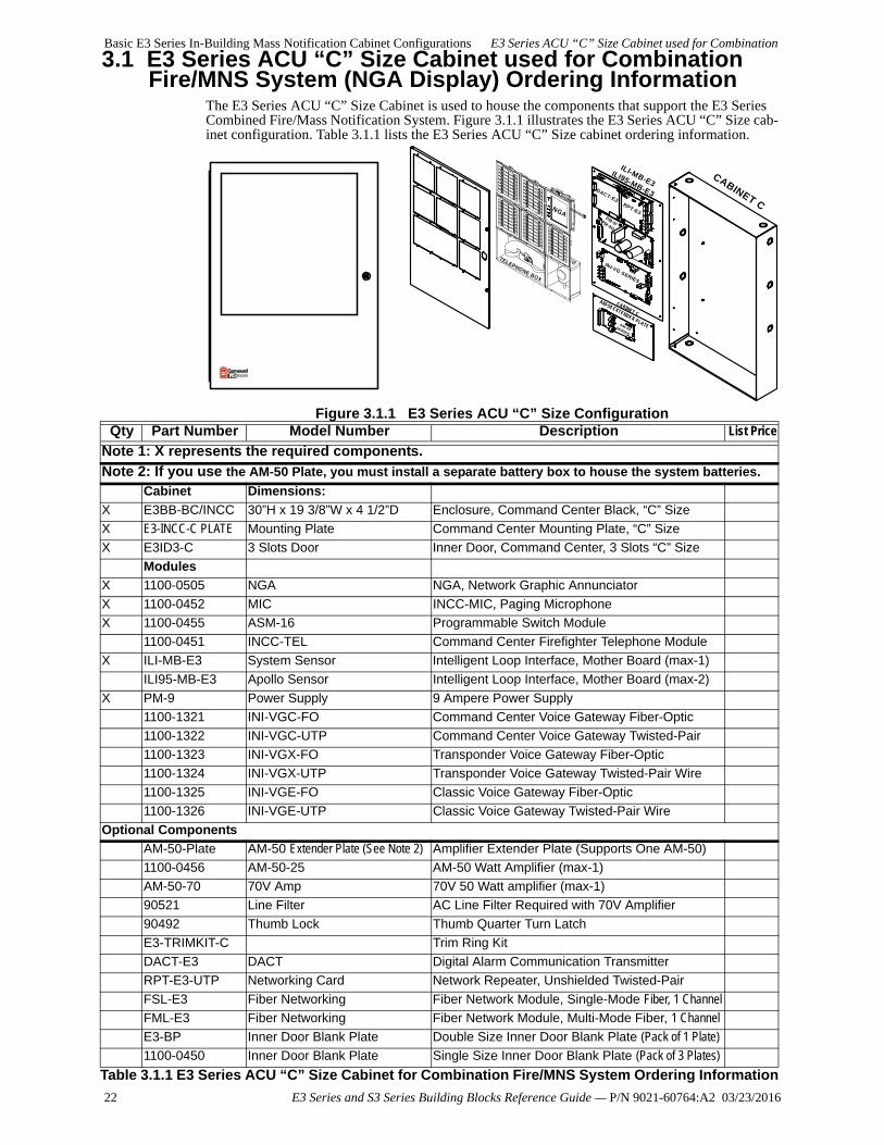
3.1 E3 Series ACU “C” Size Cabinet used for Combination Fire/MNS System (NGA Display) Ordering Information
The E3 Series ACU “C” Size Cabinet is used to house the components that support the E3 Series Combined Fire/Mass Notification System. Figure 3.1.1 illustrates the E3 Series ACU “C” Size cab-inet configuration. Table 3.1.1 lists the E3 Series ACU “C” Size cabinet ordering information.
Figure 3.1.1 E3 Series ACU “C” Size Configuration
-
NGA
CABINET C
TELEPHONE BOX
INI-VG SERIES
CABINET C
AM-50 EXTENDER PLATEAM-50SERIES
ILI-MB-E3ILI95-MB-E3
PM-9/PM-9G
DACT-E3RPT-E3
Qty Part Number Model Number Description List Price
Note 1: X represents the required components.
Note 2: If you use the AM-50 Plate, you must install a separate battery box to house the system batteries.
Cabinet Dimensions:
X E3BB-BC/INCC 30”H x 19 3/8”W x 4 1/2”D Enclosure, Command Center Black, “C” Size
X E3-INCC-C PLATE Mounting Plate Command Center Mounting Plate, “C” Size
X E3ID3-C 3 Slots Door Inner Door, Command Center, 3 Slots “C” Size
Modules
X 1100-0505 NGA NGA, Network Graphic Annunciator
X 1100-0452 MIC INCC-MIC, Paging Microphone
X 1100-0455 ASM-16 Programmable Switch Module
1100-0451 INCC-TEL Command Center Firefighter Telephone Module
X ILI-MB-E3 System Sensor Intelligent Loop Interface, Mother Board (max-1)
ILI95-MB-E3 Apollo Sensor Intelligent Loop Interface, Mother Board (max-2)
X PM-9 Power Supply 9 Ampere Power Supply
1100-1321 INI-VGC-FO Command Center Voice Gateway Fiber-Optic
1100-1322 INI-VGC-UTP Command Center Voice Gateway Twisted-Pair
1100-1323 INI-VGX-FO Transponder Voice Gateway Fiber-Optic
1100-1324 INI-VGX-UTP Transponder Voice Gateway Twisted-Pair Wire
1100-1325 INI-VGE-FO Classic Voice Gateway Fiber-Optic
1100-1326 INI-VGE-UTP Classic Voice Gateway Twisted-Pair Wire
Optional Components
AM-50-Plate AM-50 Extender Plate (See Note 2) Amplifier Extender Plate (Supports One AM-50)
1100-0456 AM-50-25 AM-50 Watt Amplifier (max-1)
AM-50-70 70V Amp 70V 50 Watt amplifier (max-1)
90521 Line Filter AC Line Filter Required with 70V Amplifier
90492 Thumb Lock Thumb Quarter Turn Latch
E3-TRIMKIT-C Trim Ring Kit
DACT-E3 DACT Digital Alarm Communication Transmitter
RPT-E3-UTP Networking Card Network Repeater, Unshielded Twisted-Pair
FSL-E3 Fiber Networking Fiber Network Module, Single-Mode Fiber, 1 Channel
FML-E3 Fiber Networking Fiber Network Module, Multi-Mode Fiber, 1 Channel
E3-BP Inner Door Blank Plate Double Size Inner Door Blank Plate (Pack of 1 Plate)
1100-0450 Inner Door Blank Plate Single Size Inner Door Blank Plate (Pack of 3 Plates)
Table 3.1.1 E3 Series ACU “C” Size Cabinet for Combination Fire/MNS System Ordering Information
E3 Series ACU “D” Size Cabinet used for Combination Fire/MNS System (NGA Display) Ordering Information Basic E3 Series
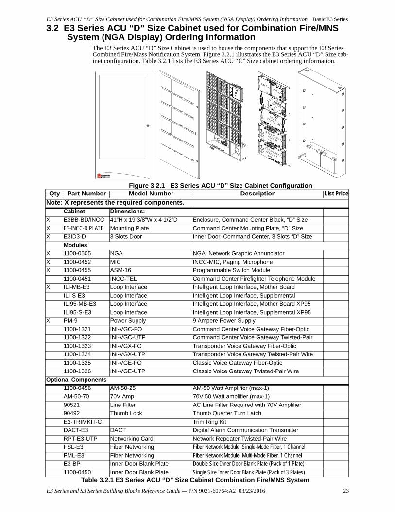
3.2 E3 Series ACU “D” Size Cabinet used for Combination Fire/MNS System (NGA Display) Ordering Information
The E3 Series ACU “D” Size Cabinet is used to house the components that support the E3 Series Combined Fire/Mass Notification System. Figure 3.2.1 illustrates the E3 Series ACU “D” Size cab-inet configuration. Table 3.2.1 lists the E3 Series ACU “C” Size cabinet ordering information.
Figure 3.2.1 E3 Series ACU “D” Size Cabinet Configuration
TELEPHON E
BOX
NGA
D A C T- E 3R P T- E 3
PM-9/PM-9G
IN I- V GS E R I E S
IL I- E 3, I LI 95- E 3
S E RI E SOR
A N X
IL I- E 3, I LI 95- E 3
S E R IE S O RA N X
Qty Part Number Model Number Description List PriceNote: X represents the required components.
Cabinet Dimensions:
X E3BB-BD/INCC 41”H x 19 3/8”W x 4 1/2”D Enclosure, Command Center Black, “D” Size
X E3-INCC-D PLATE Mounting Plate Command Center Mounting Plate, “D” Size
X E3ID3-D 3 Slots Door Inner Door, Command Center, 3 Slots “D” Size
Modules
X 1100-0505 NGA NGA, Network Graphic Annunciator
X 1100-0452 MIC INCC-MIC, Paging Microphone
X 1100-0455 ASM-16 Programmable Switch Module
1100-0451 INCC-TEL Command Center Firefighter Telephone Module
X ILI-MB-E3 Loop Interface Intelligent Loop Interface, Mother Board
ILI-S-E3 Loop Interface Intelligent Loop Interface, Supplemental
ILI95-MB-E3 Loop Interface Intelligent Loop Interface, Mother Board XP95
ILI95-S-E3 Loop Interface Intelligent Loop Interface, Supplemental XP95
X PM-9 Power Supply 9 Ampere Power Supply
1100-1321 INI-VGC-FO Command Center Voice Gateway Fiber-Optic
1100-1322 INI-VGC-UTP Command Center Voice Gateway Twisted-Pair
1100-1323 INI-VGX-FO Transponder Voice Gateway Fiber-Optic
1100-1324 INI-VGX-UTP Transponder Voice Gateway Twisted-Pair Wire
1100-1325 INI-VGE-FO Classic Voice Gateway Fiber-Optic
1100-1326 INI-VGE-UTP Classic Voice Gateway Twisted-Pair Wire
Optional Components
1100-0456 AM-50-25 AM-50 Watt Amplifier (max-1)
AM-50-70 70V Amp 70V 50 Watt amplifier (max-1)
90521 Line Filter AC Line Filter Required with 70V Amplifier
90492 Thumb Lock Thumb Quarter Turn Latch
E3-TRIMKIT-C Trim Ring Kit
DACT-E3 DACT Digital Alarm Communication Transmitter
RPT-E3-UTP Networking Card Network Repeater Twisted-Pair Wire
FSL-E3 Fiber Networking Fiber Network Module, Single-Mode Fiber, 1 Channel
FML-E3 Fiber Networking Fiber Network Module, Multi-Mode Fiber, 1 Channel
E3-BP Inner Door Blank Plate Double Size Inner Door Blank Plate (Pack of 1 Plate)
1100-0450 Inner Door Blank Plate Single Size Inner Door Blank Plate (Pack of 3 Plates)Table 3.2.1 E3 Series ACU “D” Size Cabinet Combination Fire/MNS System
E3 Series and S3 Series Building Blocks Reference Guide — P/N 9021-60764:A2 03/23/2016 23
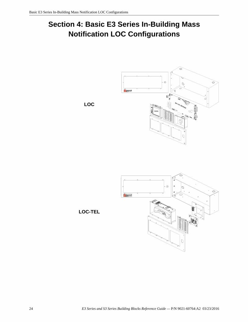
Basic E3 Series In-Building Mass Notification LOC Configurations
Section 4: Basic E3 Series In-Building Mass Notification LOC Configurations
LOC
LOC-TEL
IN I-VG SERIES
N GA
24 E3 Series and S3 Series Building Blocks Reference Guide — P/N 9021-60764:A2 03/23/2016
E3 Series LOC Local Operating Console Ordering Information Basic E3 Series In-Building Mass Notification LOC
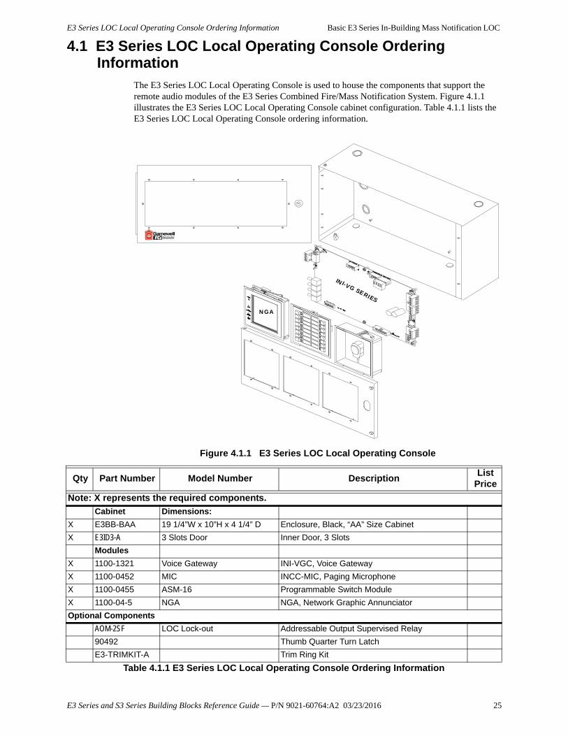
4.1 E3 Series LOC Local Operating Console Ordering Information
The E3 Series LOC Local Operating Console is used to house the components that support the remote audio modules of the E3 Series Combined Fire/Mass Notification System. Figure 4.1.1 illustrates the E3 Series LOC Local Operating Console cabinet configuration. Table 4.1.1 lists the E3 Series LOC Local Operating Console ordering information.
Figure 4.1.1 E3 Series LOC Local Operating Console
IN I-VG SERIES
N GA
Qty Part Number Model Number DescriptionList
Price
Note: X represents the required components.
Cabinet Dimensions:
X E3BB-BAA 19 1/4”W x 10”H x 4 1/4” D Enclosure, Black, “AA” Size Cabinet
X E3ID3-A 3 Slots Door Inner Door, 3 Slots
Modules
X 1100-1321 Voice Gateway INI-VGC, Voice Gateway
X 1100-0452 MIC INCC-MIC, Paging Microphone
X 1100-0455 ASM-16 Programmable Switch Module
X 1100-04-5 NGA NGA, Network Graphic Annunciator
Optional Components
AOM-2SF LOC Lock-out Addressable Output Supervised Relay
90492 Thumb Quarter Turn Latch
E3-TRIMKIT-A Trim Ring Kit
Table 4.1.1 E3 Series LOC Local Operating Console Ordering Information
E3 Series and S3 Series Building Blocks Reference Guide — P/N 9021-60764:A2 03/23/2016 25
Basic E3 Series In-Building Mass Notification LOC Configurations E3 Series LOC-TEL Local Operating Console Ordering
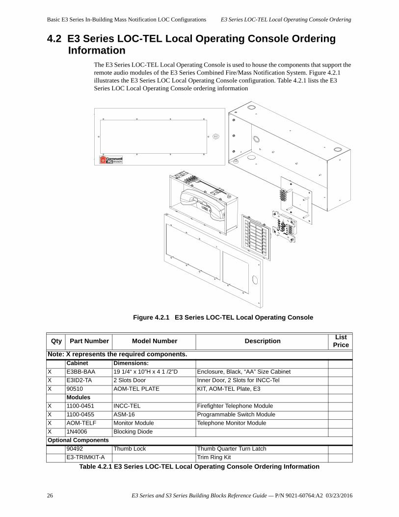
4.2 E3 Series LOC-TEL Local Operating Console Ordering Information
The E3 Series LOC-TEL Local Operating Console is used to house the components that support the remote audio modules of the E3 Series Combined Fire/Mass Notification System. Figure 4.2.1 illustrates the E3 Series LOC Local Operating Console configuration. Table 4.2.1 lists the E3 Series LOC Local Operating Console ordering information
Figure 4.2.1 E3 Series LOC-TEL Local Operating Console
Qty Part Number Model Number DescriptionList
Price
Note: X represents the required components.Cabinet Dimensions:
X E3BB-BAA 19 1/4“ x 10”H x 4 1 /2”D Enclosure, Black, “AA” Size Cabinet
X E3ID2-TA 2 Slots Door Inner Door, 2 Slots for INCC-Tel
X 90510 AOM-TEL PLATE KIT, AOM-TEL Plate, E3
Modules
X 1100-0451 INCC-TEL Firefighter Telephone Module
X 1100-0455 ASM-16 Programmable Switch Module
X AOM-TELF Monitor Module Telephone Monitor Module
X 1N4006 Blocking Diode
Optional Components
90492 Thumb Lock Thumb Quarter Turn Latch
E3-TRIMKIT-A Trim Ring Kit
Table 4.2.1 E3 Series LOC-TEL Local Operating Console Ordering Information
26 E3 Series and S3 Series Building Blocks Reference Guide — P/N 9021-60764:A2 03/23/2016
Basic E3 Series Audio Transponder Cabinet Configurations
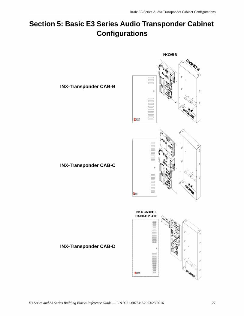
Section 5: Basic E3 Series Audio Transponder Cabinet Configurations
INX-Transponder CAB-B
INX-Transponder CAB-C
INX-Transponder CAB-D
INX CAB-B
CABINET B
BATTERIES
INI-VGX
AM-50SERIES
AM-50SERIES
BATTERIES
DACT-E3RPT-E3
INI-VG SERIES
AM-50SERIES
AM-50SERIES
PM-9/PM-9G
BATTERIES
DACT-E3RPT-E3
ILI-MB-E3/ILI95-MB-E3
INI-VGSERIES
AM-50SERIES
AM-50SERIES
INX D CABINET,E3-INX-D PLATE
E3 Series and S3 Series Building Blocks Reference Guide — P/N 9021-60764:A2 03/23/2016 27
Basic E3 Series Audio Transponder Cabinet Configurations E3 Series INX CAB-B Cabinet Ordering Information
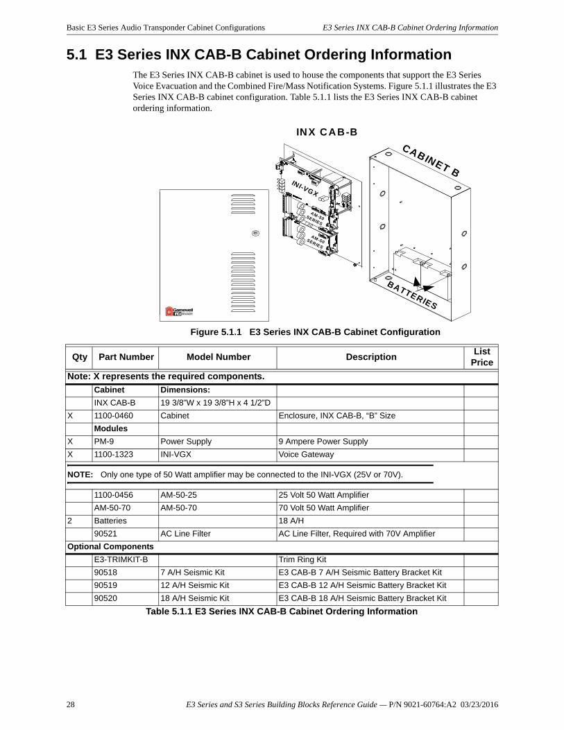
5.1 E3 Series INX CAB-B Cabinet Ordering InformationThe E3 Series INX CAB-B cabinet is used to house the components that support the E3 Series Voice Evacuation and the Combined Fire/Mass Notification Systems. Figure 5.1.1 illustrates the E3 Series INX CAB-B cabinet configuration. Table 5.1.1 lists the E3 Series INX CAB-B cabinet ordering information.
Figure 5.1.1 E3 Series INX CAB-B Cabinet Configuration
INX CAB-B
CABINET B
BATTERIES
INI-VGX
AM-50SER IES
AM-50SERIES
Qty Part Number Model Number DescriptionList
Price
Note: X represents the required components.
Cabinet Dimensions:
INX CAB-B 19 3/8”W x 19 3/8”H x 4 1/2”D
X 1100-0460 Cabinet Enclosure, INX CAB-B, “B” Size
Modules
X PM-9 Power Supply 9 Ampere Power Supply
X 1100-1323 INI-VGX Voice Gateway
NOTE: Only one type of 50 Watt amplifier may be connected to the INI-VGX (25V or 70V).
1100-0456 AM-50-25 25 Volt 50 Watt Amplifier
AM-50-70 AM-50-70 70 Volt 50 Watt Amplifier
2 Batteries 18 A/H
90521 AC Line Filter AC Line Filter, Required with 70V Amplifier
Optional Components
E3-TRIMKIT-B Trim Ring Kit
90518 7 A/H Seismic Kit E3 CAB-B 7 A/H Seismic Battery Bracket Kit
90519 12 A/H Seismic Kit E3 CAB-B 12 A/H Seismic Battery Bracket Kit
90520 18 A/H Seismic Kit E3 CAB-B 18 A/H Seismic Battery Bracket Kit
Table 5.1.1 E3 Series INX CAB-B Cabinet Ordering Information
28 E3 Series and S3 Series Building Blocks Reference Guide — P/N 9021-60764:A2 03/23/2016
E3 Series INX CAB-C Cabinet Ordering Information Basic E3 Series Audio Transponder Cabinet Configurations
E3 Series and S3 Series Building Blocks Reference Guide — P/N 9021-60764:A2 03/23/2016 29
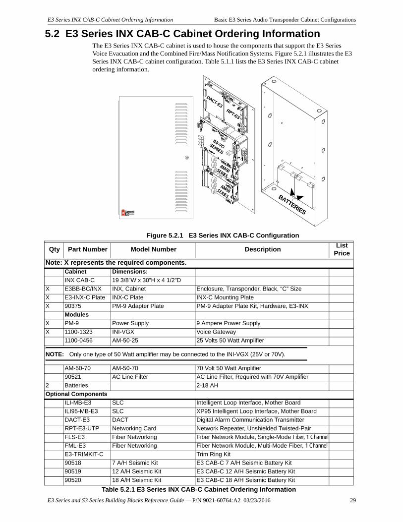
5.2 E3 Series INX CAB-C Cabinet Ordering InformationThe E3 Series INX CAB-C cabinet is used to house the components that support the E3 Series Voice Evacuation and the Combined Fire/Mass Notification Systems. Figure 5.2.1 illustrates the E3 Series INX CAB-C cabinet configuration. Table 5.1.1 lists the E3 Series INX CAB-C cabinet ordering information.
Figure 5.2.1 E3 Series INX CAB-C Configuration
BATTERIES
DACT-E3RPT-E3
INI-VG SERIES
AM-50SERIES
AM-50SERIES
Qty Part Number Model Number DescriptionList
Price
Note: X represents the required components.Cabinet Dimensions:
INX CAB-C 19 3/8”W x 30”H x 4 1/2”D
X E3BB-BC/INX INX, Cabinet Enclosure, Transponder, Black, “C” Size
X E3-INX-C Plate INX-C Plate INX-C Mounting Plate
X 90375 PM-9 Adapter Plate PM-9 Adapter Plate Kit, Hardware, E3-INX
Modules
X PM-9 Power Supply 9 Ampere Power Supply
X 1100-1323 INI-VGX Voice Gateway
1100-0456 AM-50-25 25 Volts 50 Watt Amplifier
NOTE: Only one type of 50 Watt amplifier may be connected to the INI-VGX (25V or 70V).
AM-50-70 AM-50-70 70 Volt 50 Watt Amplifier
90521 AC Line Filter AC Line Filter, Required with 70V Amplifier
2 Batteries 2-18 AH
Optional Components
ILI-MB-E3 SLC Intelligent Loop Interface, Mother Board
ILI95-MB-E3 SLC XP95 Intelligent Loop Interface, Mother Board
DACT-E3 DACT Digital Alarm Communication Transmitter
RPT-E3-UTP Networking Card Network Repeater, Unshielded Twisted-Pair
FLS-E3 Fiber Networking Fiber Network Module, Single-Mode Fiber, 1 Channel
FML-E3 Fiber Networking Fiber Network Module, Multi-Mode Fiber, 1 Channel
E3-TRIMKIT-C Trim Ring Kit
90518 7 A/H Seismic Kit E3 CAB-C 7 A/H Seismic Battery Kit
90519 12 A/H Seismic Kit E3 CAB-C 12 A/H Seismic Battery Kit
90520 18 A/H Seismic Kit E3 CAB-C 18 A/H Seismic Battery Kit
Table 5.2.1 E3 Series INX CAB-C Cabinet Ordering Information
Basic E3 Series Audio Transponder Cabinet Configurations E3 Series INX CAB-D Cabinet Ordering Information
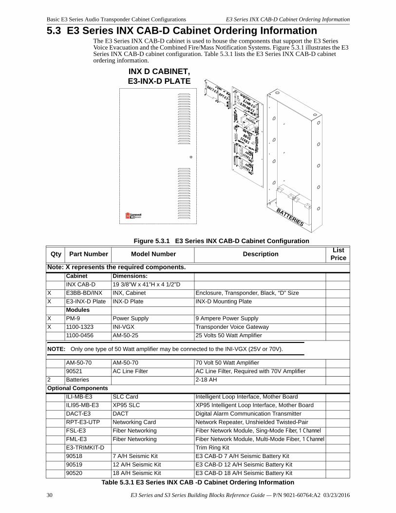
5.3 E3 Series INX CAB-D Cabinet Ordering InformationThe E3 Series INX CAB-D cabinet is used to house the components that support the E3 Series Voice Evacuation and the Combined Fire/Mass Notification Systems. Figure 5.3.1 illustrates the E3 Series INX CAB-D cabinet configuration. Table 5.3.1 lists the E3 Series INX CAB-D cabinet ordering information.
Figure 5.3.1 E3 Series INX CAB-D Cabinet Configuration
PM-9/PM-9G
BATTERIES
DACT-E3RPT-E3
ILI-MB-E3/ILI95-MB-E3
INI-VGSERIES
AM-50SERIES
AM-50SERIES
INX D CABINET,E3-INX-D PLATE
Qty Part Number Model Number DescriptionList
Price
Note: X represents the required components.Cabinet Dimensions:
INX CAB-D 19 3/8”W x 41”H x 4 1/2”D
X E3BB-BD/INX INX, Cabinet Enclosure, Transponder, Black, “D” Size
X E3-INX-D Plate INX-D Plate INX-D Mounting Plate
Modules
X PM-9 Power Supply 9 Ampere Power Supply
X 1100-1323 INI-VGX Transponder Voice Gateway
1100-0456 AM-50-25 25 Volts 50 Watt Amplifier
NOTE: Only one type of 50 Watt amplifier may be connected to the INI-VGX (25V or 70V).
AM-50-70 AM-50-70 70 Volt 50 Watt Amplifier
90521 AC Line Filter AC Line Filter, Required with 70V Amplifier
2 Batteries 2-18 AH
Optional Components
ILI-MB-E3 SLC Card Intelligent Loop Interface, Mother Board
ILI95-MB-E3 XP95 SLC XP95 Intelligent Loop Interface, Mother Board
DACT-E3 DACT Digital Alarm Communication Transmitter
RPT-E3-UTP Networking Card Network Repeater, Unshielded Twisted-Pair
FSL-E3 Fiber Networking Fiber Network Module, Sing-Mode Fiber, 1 Channel
FML-E3 Fiber Networking Fiber Network Module, Multi-Mode Fiber, 1 Channel
E3-TRIMKIT-D Trim Ring Kit
90518 7 A/H Seismic Kit E3 CAB-D 7 A/H Seismic Battery Kit
90519 12 A/H Seismic Kit E3 CAB-D 12 A/H Seismic Battery Kit
90520 18 A/H Seismic Kit E3 CAB-D 18 A/H Seismic Battery Kit
Table 5.3.1 E3 Series INX CAB -D Cabinet Ordering Information
30 E3 Series and S3 Series Building Blocks Reference Guide — P/N 9021-60764:A2 03/23/2016
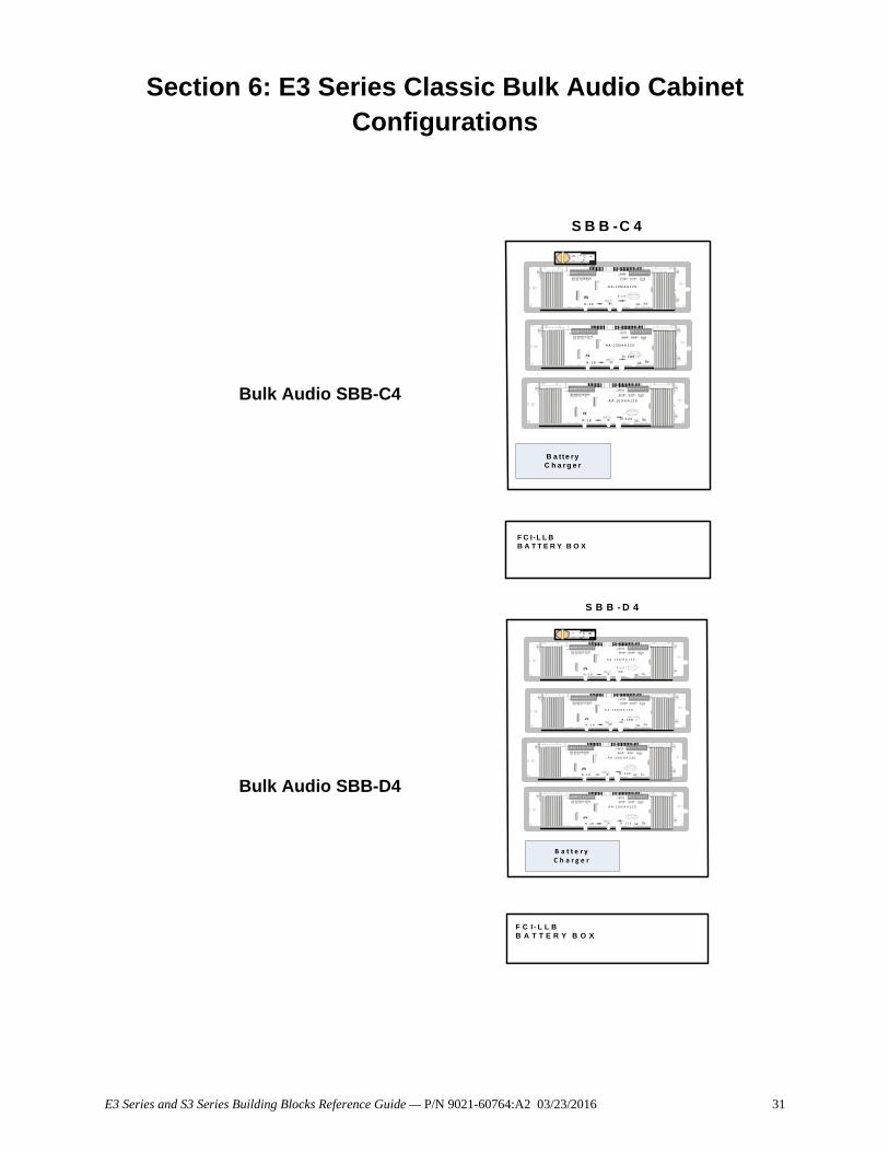
Section 6: E3 Series Classic Bulk Audio Cabinet Configurations
Bulk Audio SBB-C4
Bulk Audio SBB-D4
R - 1 8
R - 1 2 5
R - 1 8
R - 1 2 5
R - 1 8 R - 1 2 5
A A- 1 0 0/ A A 1 2 0
A A- 1 0 0/ A A 1 2 0
A A- 1 0 0/ A A 1 2 0
ACT -1
B a tte r y C h a r g e r
S B B -C 4
F C I-L L BB A T T E R Y B O X
R - 1 8
R - 1 2 5
R - 1 8
R - 1 2 5
R - 1 8 R - 1 2 5
R - 1 8 R - 1 2 5
A A - 1 0 0 / A A 1 2 0
A A - 1 0 0 / A A 1 2 0
A A - 1 0 0 / A A 1 2 0
A A - 1 0 0 / A A 1 2 0
ACT -1
B a t t e r y C h a r g e r
S B B - D 4
F C I - L L BB A T T E R Y B O X
E3 Series and S3 Series Building Blocks Reference Guide — P/N 9021-60764:A2 03/23/2016 31
E3 Series Classic Bulk Audio Cabinet Configurations E3 Series Classic, SBB-C4 Cabinet Ordering Information
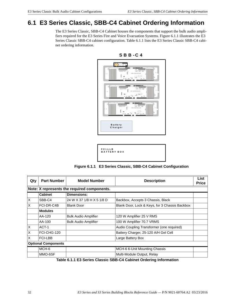
6.1 E3 Series Classic, SBB-C4 Cabinet Ordering InformationThe E3 Series Classic, SBB-C4 Cabinet houses the components that support the bulk audio ampli-fiers required for the E3 Series Fire and Voice Evacuation Systems. Figure 6.1.1 illustrates the E3 Series Classic SBB-C4 cabinet configuration. Table 6.1.1 lists the E3 Series Classic SBB-C4 cabi-net ordering information.
Figure 6.1.1 E3 Series Classic, SBB-C4 Cabinet Configuration
R - 1 8
R - 1 2 5
R - 1 8
R - 1 2 5
R - 1 8 R - 1 2 5
A A - 1 0 0/ A A 1 2 0
A A - 1 0 0/ A A 1 2 0
A A - 1 0 0/ A A 1 2 0
ACT -1
B a t t e r y C h a r g e r
S B B - C 4
F C I - L L BB A T T E R Y B O X
Qty Part Number Model Number DescriptionList
Price
Note: X represents the required components.
Cabinet Dimensions:
X SBB-C4 24 W X 37 1/8 H X 5 1/8 D Backbox, Accepts 3 Chassis, Black
X FCI-DR-C4B Blank Door Blank Door, Lock & Keys, for 3 Chassis Backbox
Modules
AA-120 Bulk Audio Amplifier 120 W Amplifier 25 V RMS
AA-100 Bulk Audio Amplifier 100 W Amplifier 70.7 VRMS
X ACT-1 Audio Coupling Transformer (one required)
X FCI-CHG-120 Battery Charger, 25-120 A/H Gel Cell
X FCI-LBB Large Battery Box
Optional Components
MCH-6 MCH-6 6-Unit Mounting Chassis
MMO-6SF Multi-Module Output, Relay
Table 6.1.1 E3 Series Classic SBB-C4 Cabinet Ordering Information
32 E3 Series and S3 Series Building Blocks Reference Guide — P/N 9021-60764:A2 03/23/2016
E3 Series Classic SBB-D4 Ordering Information E3 Series Classic Bulk Audio Cabinet Configurations
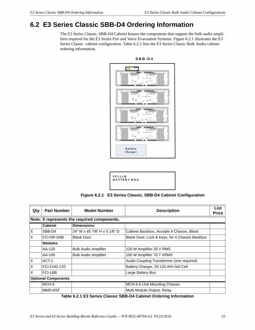
6.2 E3 Series Classic SBB-D4 Ordering InformationThe E3 Series Classic, SBB-D4 Cabinet houses the components that support the bulk audio ampli-fiers required for the E3 Series Fire and Voice Evacuation Systems. Figure 6.2.1 illustrates the E3 Series Classic cabinet configuration. Table 6.2.1 lists the E3 Series Classic Bulk Audio cabinet ordering information.
Figure 6.2.1 E3 Series Classic, SBB-D4 Cabinet Configuration
R - 1 8
R - 1 2 5
R - 1 8
R - 1 2 5
R - 1 8 R - 1 2 5
R - 1 8 R - 1 2 5
A A - 1 0 0/ A A 1 2 0
A A - 1 0 0/ A A 1 2 0
A A- 1 0 0/ A A 1 2 0
A A- 1 0 0/ A A 1 2 0
ACT -1
B a t t e r y C h a r g e r
S B B -D 4
F C I-L L BB A T T E R Y B O X
Qty Part Number Model Number DescriptionList
Price
Note: X represents the required components.
Cabinet Dimensions:
X SBB-D4 24” W x 45 7/8” H x 5 1/8” D Cabinet Backbox, Accepts 4 Chassis, Black
X FCI-DR-D4B Blank Door Blank Door, Lock & Keys, for 4 Chassis Backbox
Modules
AA-120 Bulk Audio Amplifier 120 W Amplifier 25 V RMS
AA-100 Bulk Audio Amplifier 100 W Amplifier 70.7 VRMS
X ACT-1 Audio Coupling Transformer (one required)
X FCI-CHG-120 Battery Charger, 25-120 A/H Gel Cell
X FCI-LBB Large Battery Box
Optional Components
MCH-6 MCH-6 6-Unit Mounting Chassis
MMO-6SF Multi-Module Output, Relay
Table 6.2.1 E3 Series Classic SBB-D4 Cabinet Ordering Information
E3 Series and S3 Series Building Blocks Reference Guide — P/N 9021-60764:A2 03/23/2016 33
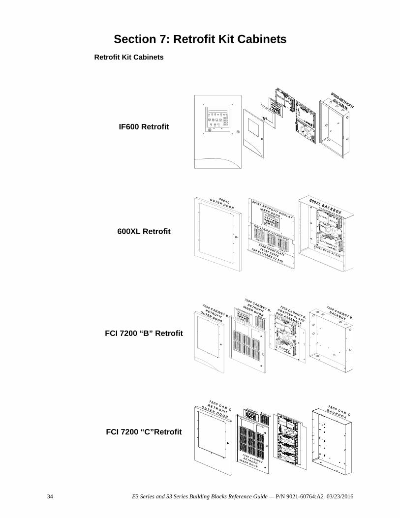
Section 7: Retrofit Kit Cabinets
Retrofit Kit Cabinets
IF600 Retrofit
600XL Retrofit
FCI 7200 “B” Retrofit
FCI 7200 “C”Retrofit
AC POWERON
POWER
FAULT
GROUNDFAUL
T
ALARM
SYSTEMTROUBLE
SUPERVISORY
SYSTEM
SILENCED
ALARMACKNOWL
EDGE
TROUBLEACKNOWL
EDGESIGNALSILENCE
SYSTEM RESET/
LAMP TEST
MENU
BACKSPACE/EDIT
OK/ENTER
LCD-E3
DACT-E3RPT-E3 ILI-MB-E3/ILI95-MB-E3
PM-9/PM-9G
IF600-RETROFIT
BACKBOX
-
-
6 0 0 X LO U T E R D O O R
L C D -E 3
R P T -E 3
D A C T -E 3
IL I -E 3 / IL I9 5 -E 3 S E R IE S
P M -9 /P M -9 G
6 0 0 X L R E T R O F IT D IS P L A Y
IN N E R D O O R
6 0 0 X L R E T R O F IT 3 -B A Y IN N E R D O O R
D E A D F R O N T P L A T E
F R O N T C O V E R
F O R B A T T E R IE S (1 2 A /H )
A S M -1 6
A S M -1 6
A S M -1 6
6 0 0 X L B A C K B O X
IL I- S -E 3 / IL I9 5 -S -E 3 6 0 0 X L B A C K P L A T E
72 00 C A B IN E T B ,
R E T R O F IT
IN N E R D O O R
720 0 C A B IN E T B ,
R E T R O F IT
O U T E R D O O R
720 0 C A B IN E T B ,
A D A P T E R P L A T E
S U B -A S S E M B L Y
7 200 C A B IN E T B ,
B A C K B O XA S M -1 6
IL I-S -E 3
P M -9 /P M -9 G
D A C T -E 3 R P T -E 3
7 2 0 0 C A B -CR E T R O F IT
O U T E R D O O R
7 2 0 0 C A B -CB A C K B O X
7 2 0 0 C A B IN E T
R E T R O F IT
IN N E R D O O R
L C D - E 3 A S M -1 6
D A C T -E 3R P T - E 3
P M -9 /P M - 9 G
IL I -S - E 3 /
IL I9 5 -S - E 3 S E R IE S
O R A N X
IL I -S -E 3 /
IL I 9 5 -S -E 3 S E R IE S
O R A N X
IL I -S -E 3 /
IL I 9 5 -S -E 3 S E R IE S
O R A N X
34 E3 Series and S3 Series Building Blocks Reference Guide — P/N 9021-60764:A2 03/23/2016
IF600-Retrofit Backbox Ordering Information Retrofit Kit Cabinets
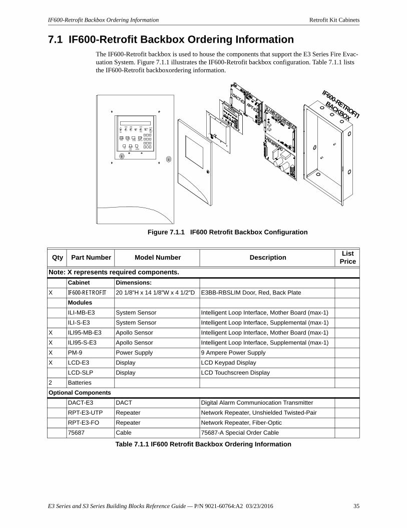
7.1 IF600-Retrofit Backbox Ordering InformationThe IF600-Retrofit backbox is used to house the components that support the E3 Series Fire Evac-uation System. Figure 7.1.1 illustrates the IF600-Retrofit backbox configuration. Table 7.1.1 lists the IF600-Retrofit backboxordering information.
Figure 7.1.1 IF600 Retrofit Backbox Configuration
AC POWERON
POWER
FAULT
GROUNDFAUL
T
ALARM
SYSTEMTROUBLE
SUPERVISORY
SYSTEM
SILENCED
ALARMACKNOWL
EDGE
TROUBLEACKNOWL
EDGESIGNALSILENCE
SYSTEM RESET/
LAMP TEST
MENU
BACKSPACE/EDIT
OK/ENTER
LCD-E3
DACT-E3RPT-E3 ILI-MB-E3/ILI95-MB-E3
PM-9/PM-9G
IF600-RETROFIT
BACKBOX
Qty Part Number Model Number DescriptionList
Price
Note: X represents required components.
Cabinet Dimensions:
X IF600-RETROFIT 20 1/8”H x 14 1/8”W x 4 1/2”D E3BB-RBSLIM Door, Red, Back Plate
Modules
ILI-MB-E3 System Sensor Intelligent Loop Interface, Mother Board (max-1)
ILI-S-E3 System Sensor Intelligent Loop Interface, Supplemental (max-1)
X ILI95-MB-E3 Apollo Sensor Intelligent Loop Interface, Mother Board (max-1)
X ILI95-S-E3 Apollo Sensor Intelligent Loop Interface, Supplemental (max-1)
X PM-9 Power Supply 9 Ampere Power Supply
X LCD-E3 Display LCD Keypad Display
LCD-SLP Display LCD Touchscreen Display
2 Batteries
Optional Components
DACT-E3 DACT Digital Alarm Communiocation Transmitter
RPT-E3-UTP Repeater Network Repeater, Unshielded Twisted-Pair
RPT-E3-FO Repeater Network Repeater, Fiber-Optic
75687 Cable 75687-A Special Order Cable
Table 7.1.1 IF600 Retrofit Backbox Ordering Information
E3 Series and S3 Series Building Blocks Reference Guide — P/N 9021-60764:A2 03/23/2016 35
Retrofit Kit Cabinets 600XL Retrofit Backbox Ordering Information
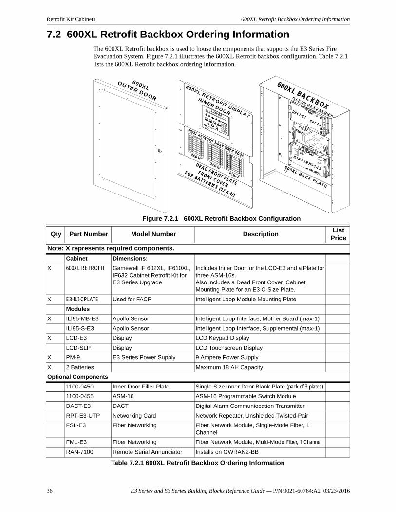
7.2 600XL Retrofit Backbox Ordering InformationThe 600XL Retrofit backbox is used to house the components that supports the E3 Series Fire Evacuation System. Figure 7.2.1 illustrates the 600XL Retrofit backbox configuration. Table 7.2.1 lists the 600XL Retrofit backbox ordering information.
Figure 7.2.1 600XL Retrofit Backbox Configuration
-
-
600X LO U TE R D O O R
LC D -E 3
R PT-E 3
D A CT -E3
IL I-E3 /IL I95 -E 3 S E R IES
PM -9 /P M -9G
600XL R ETR O FIT D ISP LA Y
IN N ER D O O R
600XL R ETR O FIT 3 -BA Y IN N ER DO O R
D E A D FR O N T P LA TE
FR O N T C O VE R
FO R B A TTE R IE S (12 A /H )
A SM -16
A SM -16
AS M-16
600XL B A C KB O X
ILI-S -E 3/IL I95 -S -E3 600X L BA C K P LA TE
Qty Part Number Model Number DescriptionList
Price
Note: X represents required components.
Cabinet Dimensions:
X 600XL RETROFIT Gamewell IF 602XL, IF610XL, IF632 Cabinet Retrofit Kit for E3 Series Upgrade
Includes Inner Door for the LCD-E3 and a Plate for three ASM-16s.Also includes a Dead Front Cover, Cabinet Mounting Plate for an E3 C-Size Plate.
X E3-ILI-CPLATE Used for FACP Intelligent Loop Module Mounting Plate
Modules
X ILI95-MB-E3 Apollo Sensor Intelligent Loop Interface, Mother Board (max-1)
ILI95-S-E3 Apollo Sensor Intelligent Loop Interface, Supplemental (max-1)
X LCD-E3 Display LCD Keypad Display
LCD-SLP Display LCD Touchscreen Display
X PM-9 E3 Series Power Supply 9 Ampere Power Supply
X 2 Batteries Maximum 18 AH Capacity
Optional Components
1100-0450 Inner Door Filler Plate Single Size Inner Door Blank Plate (pack of 3 plates)
1100-0455 ASM-16 ASM-16 Programmable Switch Module
DACT-E3 DACT Digital Alarm Communiocation Transmitter
RPT-E3-UTP Networking Card Network Repeater, Unshielded Twisted-Pair
FSL-E3 Fiber Networking Fiber Network Module, Single-Mode Fiber, 1 Channel
FML-E3 Fiber Networking Fiber Network Module, Multi-Mode Fiber, 1 Channel
RAN-7100 Remote Serial Annunciator Installs on GWRAN2-BB
Table 7.2.1 600XL Retrofit Backbox Ordering Information
36 E3 Series and S3 Series Building Blocks Reference Guide — P/N 9021-60764:A2 03/23/2016
7200 Retrofit Kit “B” Size Backbox Ordering Information Retrofit Kit Cabinets
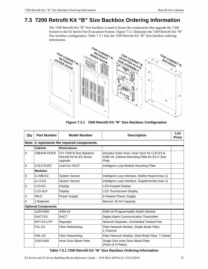
7.3 7200 Retrofit Kit “B” Size Backbox Ordering InformationThe 7200 Retrofit Kit “B” Size backbox is used to house the components that upgrade the 7200 System to the E3 Series Fire Evacuation System. Figure 7.3.1 illustrates the 7200 Retrofit Kit “B” Size backbox configuration. Table 7.3.1 lists the 7200 Retrofit Kit “B” Size backbox ordering information.
Figure 7.3.1 7200 Retrofit Kit “B” Size Backbox Configuration
7200 CABINET B,
RETROFIT
INNER DOOR
7200 CABINET B,
RETROFIT
OUTER DOOR
7200 CABINET B,
ADAPTER PLATE
SUB-ASSEMBLY
7200 CABINET B,
BACKBOXASM-16
ILI-S-E3
PM-9/PM-9G
DACT-E3 RPT-E3
Qty Part Number Model Number DescriptionList
Price
Note: X represents the required components.
Cabinet Dimensions:
X 7200-B-RETROFIT FCI 7200 B Size Backbox Retrofit Kit for E3 Series upgrade
Includes Outer Door, Inner Door for LCD-E3 & ASM-16, Cabinet Mounting Plate for E3 C-Size Plate
X E3-ILI-CPLATE Used for FACP Intelligent Loop Module Mounting Plate
Modules
X ILI-MB-E3 System Sensor Intelligent Loop Interface, Mother Board (max-1)
ILI-S-E3 System Sensor Intelligent Loop Interface, Supplemental (max-1)
X LCD-E3 Display LCD Keypad Display
LCD-SLP Display LCD Touchscreen Display
X PM-9 Power Supply 9 Ampere Power Supply
X 2 Batteries Maxium 18 AH Capacity
Optional Components
1100-0455 ASM-16 ASM-16 Programmable Switch Module
DACT-E3 DACT Digital Alarm Communication Transmitter
RPT-E3-UTP Repeater Network Repeater, Unshielded Twisted-Pair
FSL-E3 Fiber Networking Fiber Network Module, Single-Mode Fiber, 1 Channel
FML-E3 Fiber Networking Fiber Network Module, Multi-Mode Fiber, 1 Channel
1100-0450 Inner Door Blank Plate Single Size Inner Door Blank Plate (Pack of 3 Plates)
Table 7.3.1 7200 Retrofit Kit “B” Size Backbox Ordering Information
E3 Series and S3 Series Building Blocks Reference Guide — P/N 9021-60764:A2 03/23/2016 37
Retrofit Kit Cabinets 7200 Retrofit Kit “C” Size Backbox Ordering Information
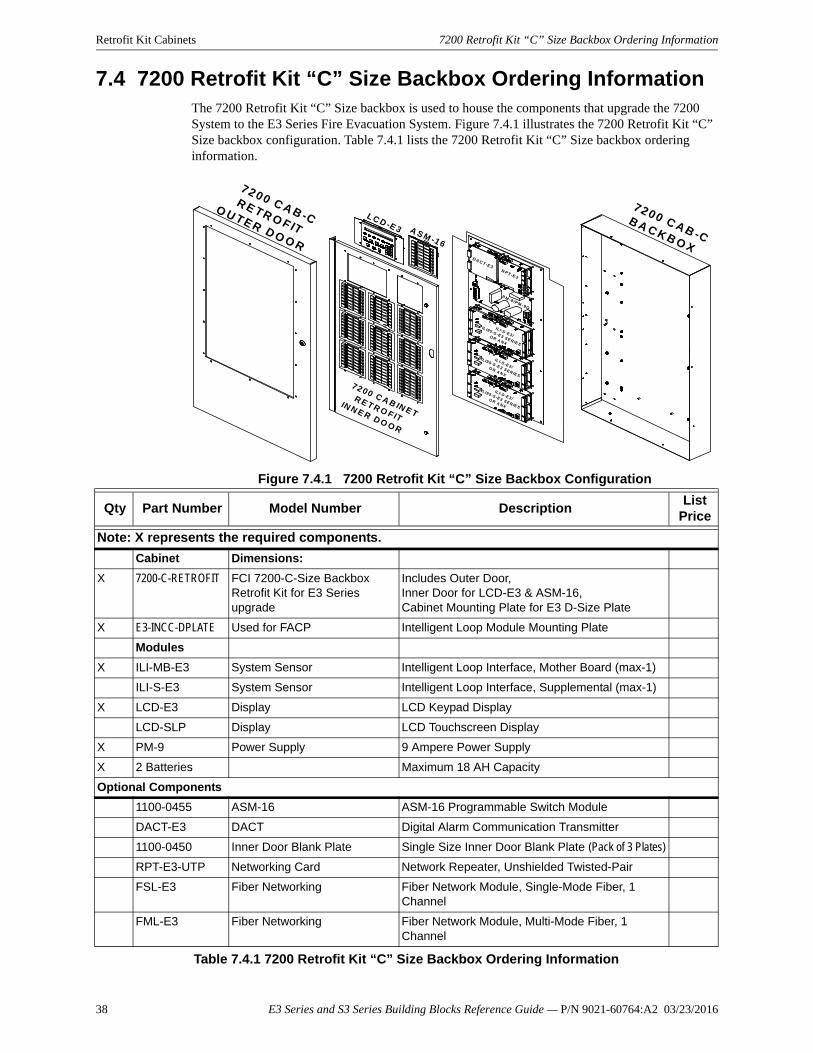
7.4 7200 Retrofit Kit “C” Size Backbox Ordering InformationThe 7200 Retrofit Kit “C” Size backbox is used to house the components that upgrade the 7200 System to the E3 Series Fire Evacuation System. Figure 7.4.1 illustrates the 7200 Retrofit Kit “C” Size backbox configuration. Table 7.4.1 lists the 7200 Retrofit Kit “C” Size backbox ordering information.
Figure 7.4.1 7200 Retrofit Kit “C” Size Backbox Configuration
7 2 0 0 C A B -CR E T R O F IT
O U T E R D O O R
7 2 0 0 C A B -CB A C K B O X
72 00 C A B IN E T
R E T R O F IT
IN N E R D O O R
L C D -E 3 A S M -1 6
D A C T -E 3R P T -E 3
P M -9 /P M -9G
IL I-S -E 3 /
IL I9 5 -S -E 3 S E R IE S
O R A N X
IL I-S -E 3 /
IL I9 5 -S -E 3 S E R IE S
O R A N X
IL I-S -E 3 /
IL I9 5 -S -E 3 S E R IE S
O R A N X
Qty Part Number Model Number DescriptionList
Price
Note: X represents the required components.
Cabinet Dimensions:
X 7200-C-RETROFIT FCI 7200-C-Size Backbox Retrofit Kit for E3 Series upgrade
Includes Outer Door, Inner Door for LCD-E3 & ASM-16, Cabinet Mounting Plate for E3 D-Size Plate
X E3-INCC-DPLATE Used for FACP Intelligent Loop Module Mounting Plate
Modules
X ILI-MB-E3 System Sensor Intelligent Loop Interface, Mother Board (max-1)
ILI-S-E3 System Sensor Intelligent Loop Interface, Supplemental (max-1)
X LCD-E3 Display LCD Keypad Display
LCD-SLP Display LCD Touchscreen Display
X PM-9 Power Supply 9 Ampere Power Supply
X 2 Batteries Maximum 18 AH Capacity
Optional Components
1100-0455 ASM-16 ASM-16 Programmable Switch Module
DACT-E3 DACT Digital Alarm Communication Transmitter
1100-0450 Inner Door Blank Plate Single Size Inner Door Blank Plate (Pack of 3 Plates)
RPT-E3-UTP Networking Card Network Repeater, Unshielded Twisted-Pair
FSL-E3 Fiber Networking Fiber Network Module, Single-Mode Fiber, 1 Channel
FML-E3 Fiber Networking Fiber Network Module, Multi-Mode Fiber, 1 Channel
Table 7.4.1 7200 Retrofit Kit “C” Size Backbox Ordering Information
38 E3 Series and S3 Series Building Blocks Reference Guide — P/N 9021-60764:A2 03/23/2016
Manufacturer Warranties and Limitation of LiabilityManufacturer Warranties. Subject to the limitations set forth herein,Manufacturer warrants that the Products manufactured by it in itsNorthford, Connecticut facility and sold by it to its authorizedDistributors shall be free, under normal use and service, from defectsin material and workmanship for a period of thirty six months (36)months from the date of manufacture (effective Jan. 1, 2009). TheProducts manufactured and sold by Manufacturer are date stamped atthe time of production. Manufacturer does not warrant Products thatare not manufactured by it in its Northford, Connecticut facility butassigns to its Distributor, to the extent possible, any warranty offeredby the manufacturer of such product. This warranty shall be void if aProduct is altered, serviced or repaired by anyone other thanManufacturer or its authorized Distributors. This warranty shall alsobe void if there is a failure to maintain the Products and the systems inwhich they operate in proper working conditions.
MANUFACTURER MAKES NO FURTHER WARRANTIES, ANDDISCLAIMS ANY AND ALL OTHER WARRANTIES, EITHEREXPRESSED OR IMPLIED, WITH RESPECT TO THE PRODUCTS,TRADEMARKS, PROGRAMS AND SERVICES RENDERED BYMANUFACTURER INCLUDING WITHOUT LIMITATION,INFRINGEMENT, TITLE, MERCHANTABILITY, OR FITNESS FORANY PARTICULAR PURPOSE. MANUFACTURER SHALL NOT BELIABLE FOR ANY PERSONAL INJURY OR DEATH WHICH MAYARISE IN THE COURSE OF, OR AS A RESULT OF, PERSONAL,COMMERCIAL OR INDUSTRIAL USES OF ITS PRODUCTS.
This document constitutes the only warranty made by Manufacturerwith respect to its products and replaces all previous warranties and isthe only warranty made by Manufacturer. No increase or alteration,written or verbal, of the obligation of this warranty is authorized.Manufacturer does not represent that its products will prevent any lossby fire or otherwise.
Warranty Claims. Manufacturer shall replace or repair, atManufacturer's discretion, each part returned by its authorizedDistributor and acknowledged by Manufacturer to be defective,provided that such part shall have been returned to Manufacturer with
all charges prepaid and the authorized Distributor has completedManufacturer's Return Material Authorization form. The replacementpart shall come from Manufacturer's stock and may be new orrefurbished. THE FOREGOING IS DISTRIBUTOR'S SOLE ANDEXCLUSIVE REMEDY IN THE EVENT OF A WARRANTY CLAIM.Warn-HL-08-2009.fm
E3 Series and S3 Series Building Blocks Reference Guide — P/N 9021-60764:A2 03/23/2016 39

Gamewell-FCI12 Clintonville Road
Northford, CT 06472-1610 USA203-484-7161
fax 203-484-7118
www.gamewell-fci.com