Embed Size (px)
Citation preview

Producing Solutions
E2000 CHEMICAL METERING PUMP
MODEL: _______________ CAPACITY: _______________ PRESSURE: _______________ SERIAL #: _______________
Enchlor Inc. 130 West Main Street, Silverdale, PA 18962 Phone: 215-453-2533 Fax: 215-453-1101
www.enchlor.com
1. SAFETY .....................................................................................................1 1.1 General................................................................................................................. 1 1.2 Mechanical Precautions .......................................................................................... 1 1.3 Electrical Precautions ............................................................................................. 1
2. INTRODUCTION ........................................................................................2
3. INSTALLATION .........................................................................................2
4. PIPING .......................................................................................................2 4.1 General................................................................................................................. 2 4.2 Suction ................................................................................................................. 3 4.3 Discharge.............................................................................................................. 4 4.4 Piping Arrangement ............................................................................................... 1
5. OPERATION ..............................................................................................2 5.1 Before Starting ...................................................................................................... 2 5.2 After Starting ........................................................................................................ 2
6. CAPACITY ADJUSTMENT........................................................................2
7. MAINTENANCE .........................................................................................3 7.1 Pre Maintenance Cleaning....................................................................................... 3 7.2 Lubrication ............................................................................................................ 3 7.3 Suction & Discharge Valves .................................................................................... 3 7.4 Diaphragm ............................................................................................................ 4
8. TROUBLESHOOTING ...............................................................................5
9. 2000 SERIES METERING PUMP ..............................................................8 9.1 Drive End – Side Elevation ..................................................................................... 8 9.2 Drive End - Front Elevation and Adjustment Knob Locking Device.............................. 9 9.3 Drive End – Parts List........................................................................................... 10 9.4 Solution End 2000-001 - PVC ............................................................................. 11 9.5 Solution End 2000-001 - PVC Parts List ............................................................... 12 9.6 Solution End 2000-001 - SS ............................................................................... 13 9.7 Solution End 2000-001 - SS Parts List ................................................................. 14 9.8 Solution End 2000-002 - PVC ............................................................................. 15 9.9 Solution End 2000-002 - PVC Parts List ............................................................... 16 9.10 Solution End 2000-002 - SS ............................................................................... 17 9.11 Solution End 2000-002 - Stainless Steel Parts List ............................................... 18 9.12 Solution End 2000-005 - PVC ............................................................................. 19 9.13 Solution End 2000-005 - PVC Parts List ............................................................... 20 9.14 Solution End 2000-005 - SS ............................................................................... 21 9.15 Solution End 2000-005 - Stainless Steel Parts List ............................................... 22 9.16 Solution End 2000-015 - PVC ............................................................................. 23 9.17 Solution End 2000-015 - PVC Parts List ............................................................... 24 9.18 Solution End 2000-015 - SS ............................................................................... 25 9.19 Solution End 2000-015 - Stainless Steel Parts List ............................................... 26
10. CALIBRATION OF A METERING PUMP ................................................27 CALIBRATION CYLINDER – INSTALLATION GUIDE.................................................. 28
11. SERIES 500 VALVE INSTRUCTIONS.....................................................29
APPENDIX..................................................ERROR! BOOKMARK NOT DEFINED.
MP2000 Updated May 2004
METERING PUMPS 2000 SERIES
1. SAFETY
1.1 General
Please read and familiarise yourself with all sections of this and other equipment manuals before proceeding with installation.
Observe all standard precautions which apply to moving machinery.
Observe all standard precautions which apply to electrical equipment, drives and controls.
Pay particular attention to special safety 'cautions' and 'notes' in this manual.
1.2 Mechanical Precautions
Prior to undertaking any mechanical maintenance repair, installation, etc.
SWITH OFF, and disconnect power before proceeding.
Personnel must wear the appropriate protective safety attire and remove loose clothing, jewellery etc.
1.3 Electrical Precautions
Before undertaking work on the electrical controls or drives, disconnect power
and place a notice to advise others of the type of work in process.
Ensure all necessary grounds are in place and solid.
Do not disconnect or disable ground connections
CAUTION Follow all electrical regulations where required by electrical engineering trades.

2. INTRODUCTION Enchlor metering pumps are designed and manufactured for long, low maintenance service life and when properly applied, will give many years of consistent accurate metering and trouble free operation. The following instructions should be read and followed to correctly install and operate the pump and ensure optimum pump life and performance. Sectional arrangement drawings and Part Lists are enclosed at the end of this manual.
3. INSTALLATION 3.1 It is desirable to locate the pump as close as possible to the supply source (eg tank)
in order to minimise friction losses in the suction line. 3.2 The pump should be located with sufficient free space provided around the pump to
allow access for:
Adjustment of the manual capacity adjustment advice;
To facilitate ease of routine and breakdown maintenance. 3.3 The mounting surface should be even and level. The pump base (mounting plate) is
provided with four (4) holes for mounting bolts.
4. PIPING
4.1 General
4.1.1 The pump suction valve is located at the bottom of the pump head and the
discharge vale on top. The pump cannot operate without these valves and for correct operation, valves must be vertical.
4.1.2 Discharge pressure should be more than 20 kPa greater than suction
pressure to prevent over feeding or syphoning and to maintain metering accuracy.
NOTE: When the difference is less than 20 kPa, a back pressure valve and pulsation dampener should be installed in the discharge line. The pulsation dampener should be located between pump and valve, as close to the pump as possible.
4.1.3 A characteristic of reciprocating pump performance is pulsating flow. Piping
should be sized for flow rates at least 3.5 times greater than maximum capacity of pumps.
NOTE: Small diameter piping will produce unpredictable flow rates and system pressures.

MP2000 Updated May 2004
4.1.4 Piping should be as short and straight as possible and arranged to avoid
loops or pockets where gas may accumulate.
4.1.5 All piping should be separately supported close to the pump to avoid imposing pipe loads on the pump. When handling high or low temperature liquids, measures should be taken to prevent distortion of piping imposing loads on the pump.
4.1.6 All pipe work should be flushed clean of any solids, which may be present in
the pipe work (i.e. weld slag, dirt following construction or repair) before final connection to the pump and start-up.
4.1.7 Make provision in discharge piping where necessary to facilitate initial
priming of pumps against reduced pressure.
4.1.8 Capacity adjustment range for accuracy of metering, avoid over sizing of metering pumps. Flow rates of less than 10% of pump maximum capacity may produce unacceptable accuracy.
4.1.9 Where lengthy suction and discharge pipelines are involved or there is
limitation on size, install pulsation dampeners close to the pump to:
Avoid cavitation – maintain metering accuracy.
Reduce amplitude of pulsations
4.1.10 Ensure that the drain line from any pressure relief valve in the system is:
Suitably sized to ensure correct operation of the relief valve.
Returns to the suction tank.
Is fitted with a sight glass for visual indication.
4.2 Suction
4.2.1 Piping must be air tight. 4.2.2 For ease of maintenance an isolating valve should be located near the pump
inlet.
4.2.3 Solids should be prevented from entering low volume pumps or pumps used for high accuracy metering. A strainer of 150-200 mesh is recommended and should be of adequate size to prevent restriction of flow.
4.2.4 Suction pipe entrance should be at least 75 mm from the bottom of solution
tank to allow settlement of larger solids in the tank.
4.2.5 Make provision in suction piping where necessary to facilitate automatic venting of any gases likely to accumulate.

4.3 Discharge
4.3.1 Should it be necessary to install an isolating valve in the discharge line, a
relief valve must be installed between the pump and isolating valve. 4.3.2 The 2000 Series Metering Pump, being a positive displacement pump, will be
damaged if operated against a closed valve.
NOTE: The relief valve should be set to operate at the maximum rated pump discharge pressure or maximum system operating pressure, whichever is lower.
CAUTION: When pumping hazardous liquids the relief valve discharge should be piped
back to the supply source. NOTE: Where relief valve is likely to operate frequently, to ensure correct operation
and maximise valve life, a pulsation dampener should be installed between valve and pump
4.3.3 A pressure gauge with gauge protector should be installed to check if the
pump is not operating at too great a discharge pressure. Gauge should be provided with petcock for isolation from system when not required.
4.3.4 When pumping into a high pressure system, a non return valve should be
installed as a safety precaution at the injection point.
4.3.5 Make provision in pipe work to facilitate priming against reduced pressure.

MP2000 Updated May 2004
4.4 Piping Arrangement
Should it be necessary to install an isolating valve in the discharge line, a relief valve must be installed in the line between the pump and isolating valve.
WRONG CORRECT
Metering pumps are positive displacement pumps and produce pulsating flow. Consequently there is considerable line pressure loss and suction piping should be sized to ensure adequate NPSHA. If piping extends for a considerable distance a suitable break tank or pulsation dampener should be installed near pump. the pump.
Avoid pockets or loops in piping where gas may accumulate.
WRONG CORRECT
Where the pump discharge line connects with a high pressure line, install a non return valve as a safety precaution.
The presence of solids in the pumped liquid can cause incorrect pump valve operation and affect metering accuracy. If solids are present install a strainer with 150 to 200 mesh
and large mesh surface in order to keep pressure drop as small as possible and ensure that strainer does not become
quickly clogged.
CORRECT

5. OPERATION
5.1 Before Starting
5.1.1 Ensure the pump will be operated within its specification. 5.1.2 Check gearbox oil level. Prior to leaving factory, each pump is filled to the
correct level with the recommended grade of oil (see maintenance section). 5.1.3 Check direction of rotation. Correct direction is clockwise when viewing
pump from top of motor.
5.1.4 Ensure system control of isolating valves in discharge line is open.
5.2 After Starting
5.2.1 Pump will normally prime automatically. However, it may be necessary to
run the pump at maximum capacity to clear air. If this is unsuccessful install a return line from discharge pipe to supply tank with valve to facilitate priming at reduced pressure and/or air release.
CAUTION: If pumped liquid is hazardous do not disconnect discharge pipe work.
5.2.2 Check that pump is operating correctly against discharge pressure. 5.2.3 Ensure that any problems are noted and appropriate corrective or
preventative action is taken.
6. CAPACITY ADJUSTMENT 6.1 Standard manual capacity adjustment is by means of a control knob located on the
side of the pump. 6.2 Adjustment should be made whilst the pump is running. To adjust whilst stopped
will cause damage to the pump mechanism.

MP2000 Updated May 2004
7. MAINTENANCE
7.1 Pre Maintenance Cleaning
Flush pump liquid head internals to remove all chemical residue.
Clean the pump's exterior to ensure chemical free surface.
Check that appropriate chemical handling and cleaning standards have been met.
CAUTION: Enchlor (AUST) PTY LTD IS UNABLE TO ACCEPT ANY METERING PUMP RETURNED
FOR MAINTENANCE THAT HAS NOT BEEN SUITABLY CLEANED.
It is an Enchlor Quality Assurance policy that all equipment returned for repair or service be supplied with a completed copy of the 'Equipment Decontamination Advice' form, as shown on page 39 of this manual.
7.2 Lubrication
7.2.1 Change oil after 750 hours of operation and at 4,500 hours intervals
thereafter. The following are recommended grades: SHELL : OMALA 320 BP : GR-XP-320 ISO MOBIL : MOBIL GEAR 632 CASTROL : ALPHA SP 320 7.2.2 Fill oil until oil starts to overflow from the filler port. Oil volume : 450 ml
7.3 Suction & Discharge Valves
7.3.1 During routine maintenance, valves should be dismantled and checked.
Replace worn ball checks and valve seats. When pumping clean liquids of moderate viscosity, valves will give many years of trouble free service. However, valve life can be reduced in applications where discharge pressure is high, liquid viscosity low or solids are present.
NOTE: Should it be necessary to service the valves, cleanliness is essential and care should be taken to avoid damaging components.
Refer to valve drawing at end of manual prior to dismantling.
7.3.2 When reassembling, ensure that all O-Rings, ball checks and ball stops are in
the correct position. Failure to fit ball stops can result in closed head situation and severe pump damage.
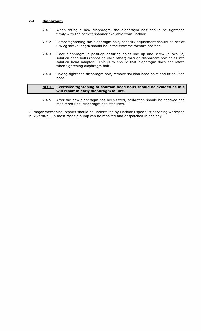
7.4 Diaphragm
7.4.1 When fitting a new diaphragm, the diaphragm bolt should be tightened
firmly with the correct spanner available from Enchlor.
7.4.2 Before tightening the diaphragm bolt, capacity adjustment should be set at 0% eg stroke length should be in the extreme forward position.
7.4.3 Place diaphragm in position ensuring holes line up and screw in two (2)
solution head bolts (opposing each other) through diaphragm bolt holes into solution head adaptor. This is to ensure that diaphragm does not rotate when tightening diaphragm bolt.
7.4.4 Having tightened diaphragm bolt, remove solution head bolts and fit solution
head.
NOTE: Excessive tightening of solution head bolts should be avoided as this will result in early diaphragm failure.
7.4.5 After the new diaphragm has been fitted, calibration should be checked and
monitored until diaphragm has stabilised. All major mechanical repairs should be undertaken by Enchlor's specialist servicing workshop in Silverdale. In most cases a pump can be repaired and despatched in one day.

MP2000 Updated May 2004
8. TROUBLESHOOTING
Trouble Cause Corrections
Blown electrical. Fuse. Check cause and change to suitable capacity fuse
Electrical overload relay trips.
Change relay capacity to correct value.
Electrical wiring breakdown or defective contact.
Change or reconnect.
Low voltage. Difference in supply voltage and rated voltage of motor.
Find cause and correct.
Defective motor. Check and replace.
Excessive pressure in discharge line.
Reduce pressure.
Valve in discharge line closed.
Open valve
(A) Pump does not start.
Pump discharge valve incorrectly reassembled during maintenance. Ball stop cushion missing
Reassemble correctly.
Air in liquid end. Relieve pressure in discharge line.
Valve in discharge line closed.
Open valve.
(B) No Flow
Pump discharge valve incorrectly reassembled during maintenance. Ball stop cushion missing.
Reassemble correctly.
Overload relay Reset the switch after checking the cause and correcting.
Discharge pipe clogged. Clear the pipe.
Valve in discharge line closed.
Open valve.
(C) Pump does not work after operating normally
Pump discharge valve incorrectly reassembled during maintenance. Ball stop cushion missing.
Reassemble correctly

Trouble Cause Corrections
Valve clogged. Clean.
Worn valve seat. Replace seat or valve.
Flow meter incorrect. Inspect meter, repair or change.
Leakage from relief valve. Inspect, repair or change.
Air leaking into suction piping
Check for leak source and repair.
Air lock in suction line. Review suction pipework layout to eradicate air pockets.
(D) Reduced pump flow rate or unstable rate.
Change in pump rpm Correct electric power sources, speed control etc.
Insufficient NPSH available: (a) Suction pipe diameter
too small. (b) Suction lift too great.
Enlarge suction pipe, or install accumulator in the line close to pump or raise level of tank. Raise liquid level.
Viscosity of liquid too high. 1. Heat or lower viscosity by other means.
2. Increase suction pipe diameter.
3. Increase suction pressure.
Vapour pressure high. 1. Lower liquid
temperature at inlet port.
2. Raise liquid level.
Suction piping and/or valve clogged
Clean
(E) Reduced pump flow rate. Unstable flow rate. Flow rate does not increase as stroke length is increased. Cavitation noise may be apparent.
Suction strainer clogged or too small
Clean or replace with larger unit.

MP2000 Updated May 2004
Trouble Cause Correction
Pressure difference across pump less than 20 KPa
Increase pressure difference (ie install back pressure valve).
(F) Excessive pump flow rate.
Flow continues after pump has stopped.
Discharge line too long or diameter too small
Reduce length and/or increase diameter. Install accumulator in discharge line.
(G) Liquid leakage from pump adaptor drain
Ruptured diaphragm. Check/replace diaphragm.
(H) Knocking sound in gearbox
Excessive discharge pressure
Check discharge pressure.
Rhythmic noise of pump valves
Normal (I) Liquid end noise
Clogged discharge or suction valve
Clean
Improper voltage Adjust voltage to motor specification.
Overload (Refer to Section K).
(J) Overheating of motor
Inadequate ventilation Change motor or relocate
Improper Oil Change
Discharge pressure too high
Lower to permissible pressure
(K) Overload
Erratic noise of pump valves
1. Clean valves. 2. Increase pressure
difference (ie install back pressure valve).

9. 2000 SERIES METERING PUMP
9.1 Drive End – Side Elevation
MP2000 Updated May 2004
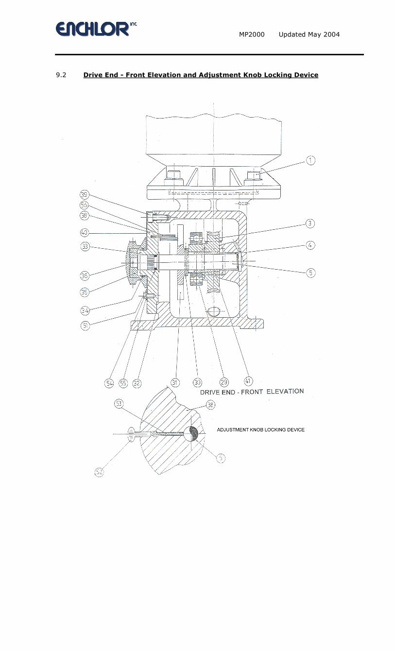
9.2 Drive End - Front Elevation and Adjustment Knob Locking Device

9.3 Drive End – Parts List
ITEM PART NO DESCRIPTION QTY NOTES
1 08/01/114 SCREW (MOTOR) 4 3 10312 WORM WHEEL 1 ◊⊗ 4 06/04/07 BUSH (MAIN SHAFT) 1 5 10301 MAIN SHAFT 1 6 08/12/02 DRAIN PLUG 1 7 E-42 WORM 1 ◊⊗ 8 10/01/11 PIN (DRIVE MOTOR) 2 9 08/12/03 OIL FILL PLUG 1 10 10261-063 WORM EXTENSION SHAFT 1 □ 11 SPECIFICATION DRIVE MOTOR 1 12 10302 PRIMARY PISTON 1 13 11/01/21 CIRCLIP (STRIKER SHAFT) 1 26 10311 SPRING RETURN 2 27 10303 STRIKER SHAFT 1 28A 10304 (- 015) PUMP BODY 1 28B 10321 (1-5) PUMP BODY 1 29 06/01/33 BEARING ECCENTRIC 1 30 10/01/19 PIN (MAIN SHAFT) 1 31 10305 CAM 1 ◊ 32 10306 GASKET (END COVER) 1 33 11/01/21 CIRCLIP (MAIN SHAFT) 2 34 07/03/47 'O'-RING (ADJUSTMENT KNOB) 1 35 A10307 KNOB – ADJUSTMENT 1 36 10/01/17 PIN (ADJUSTMENT KNOB) 1 38 10308 END COVER 1 39 08/01/87 SCREW (END COVER) 4 40 10309 DIAL PLATE 1 41 06/05/03 INNER RING 1 48 10314 GASKET (MOTOR FLANGE) 1 50 08/13/16 GRUB SCREW 2 51 07/03/46 'O'-RING 1 52 08/08/10 THUMB SCREW 1 53 10323 COMPRESSION PAD 1 54 08/05/25 SCREW (DIAL PLATE) 1 55 09/01/30 WASHER (DIAL PLATE) 1 56 10/01/22 SELOC PIN 2
Notes: ⊗ State Head Size
◊ State Stroking Rate (SPM)
□ State Drive Motor Frame Size

MP2000 Updated May 2004
9.4 Solution End 2000-001 - PVC
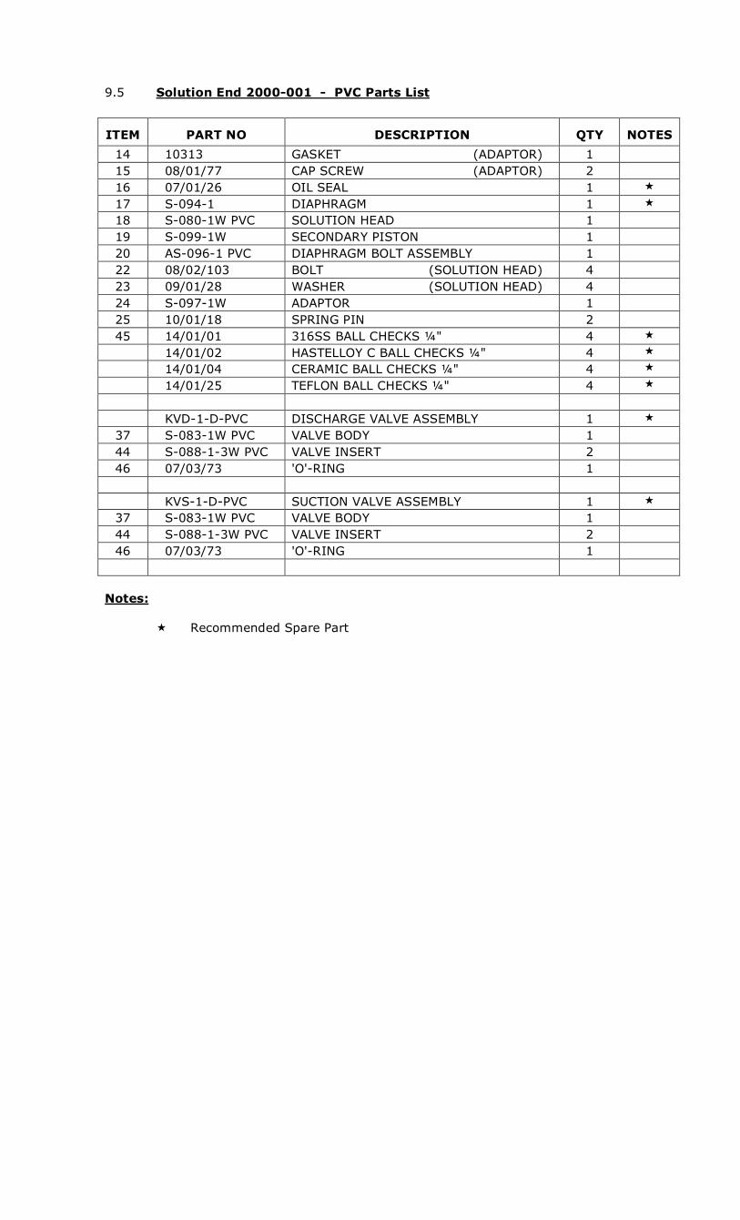
9.5 Solution End 2000-001 - PVC Parts List
ITEM PART NO DESCRIPTION QTY NOTES
14 10313 GASKET (ADAPTOR) 1 15 08/01/77 CAP SCREW (ADAPTOR) 2 16 07/01/26 OIL SEAL 1 17 S-094-1 DIAPHRAGM 1 18 S-080-1W PVC SOLUTION HEAD 1 19 S-099-1W SECONDARY PISTON 1 20 AS-096-1 PVC DIAPHRAGM BOLT ASSEMBLY 1 22 08/02/103 BOLT (SOLUTION HEAD) 4 23 09/01/28 WASHER (SOLUTION HEAD) 4 24 S-097-1W ADAPTOR 1 25 10/01/18 SPRING PIN 2 45 14/01/01 316SS BALL CHECKS ¼" 4 14/01/02 HASTELLOY C BALL CHECKS ¼" 4
14/01/04 CERAMIC BALL CHECKS ¼" 4
14/01/25 TEFLON BALL CHECKS ¼" 4
KVD-1-D-PVC DISCHARGE VALVE ASSEMBLY 1
37 S-083-1W PVC VALVE BODY 1 44 S-088-1-3W PVC VALVE INSERT 2 46 07/03/73 'O'-RING 1 KVS-1-D-PVC SUCTION VALVE ASSEMBLY 1
37 S-083-1W PVC VALVE BODY 1 44 S-088-1-3W PVC VALVE INSERT 2 46 07/03/73 'O'-RING 1
Notes: Recommended Spare Part

MP2000 Updated May 2004
9.6 Solution End 2000-001 - SS

9.7 Solution End 2000-001 - Stainless Steel Parts List
ITEM PART NO DESCRIPTION QTY NOTES
14 10313 GASKET (ADAPTOR) 1 15 08/01/77 CAP SCREW (ADAPTOR) 2 16 07/01/26 OIL SEAL 1 17 S-094-1 DIAPHRAGM 1 18 S-080-1W SS SOLUTION HEAD 1 19 S-099-1W SECONDARY PISTON 1 20 AS-096-1 SS DIAPHRAGM BOLT ASSEMBLY 1 22 08/02/103 BOLT (SOLUTION HEAD) 4 23 09/01/28 WASHER (SOLUTION HEAD) 4 24 S-097-1W ADAPTOR 1 25 10/01/18 SPRING PIN 2 45 14/01/01 316SS BALL CHECKS ¼" 4 KVD-1-D-SS DISCHARGE VALVE ASSEMBLY 1
37 S-083-1-3W SS VALVE BODY 1 44 S-088-1W PTFE VALVE INSERT 2 46 07/03/73 'O'-RING 1 KVS-1-D-SS SUCTION VALVE ASSEMBLY 1
37 S-083-1-3W SS VALVE BODY 1 44 S-088-1-3W PTFE VALVE INSERT 2 46 07/03/73 'O'-RING 1
Notes:
Recommended Spare Part

MP2000 Updated May 2004
9.8 Solution End 2000-002 - PVC

9.9 Solution End 2000-002 - PVC Parts List
ITEM PART NO DESCRIPTION QTY NOTES
14 10313 GASKET (ADAPTOR) 1 15 08/01/77 CAP SCREW (ADAPTOR) 2 16 07/01/26 OIL SEAL 1 17 S-094-2-3 DIAPHRAGM 1 18 S-080-2 PVC SOLUTION HEAD 1 19 S-099-2W SECONDARY PISTON 1 20 AS-096-2 PVC DIAPHRAGM BOLT ASSEMBLY 1 22 08/02/103 BOLT (SOLUTION HEAD) 4 23 09/01/28 WASHER (SOLUTION HEAD) 4 24 S-097-2W ADAPTOR 1 25 10/01/18 SPRING PIN 2 45 14/01/01 316SS BALL CHECKS ¼" 2 14/01/02 HASTELLOY C BALL CHECKS ¼" 2
14/01/04 CERAMIC BALL CHECKS ¼" 2
14/01/25 TEFLON BALL CHECKS ¼" 2
KVD-2-3-S-PVC DISCHARGE VALVE ASSEMBLY 1
37 S-084-2-3W PVC VALVE BODY 1 44 E-16 PVC STOP BALL CHECK (DISCHARGE) 1 46 07/03/03 'O'-RING 1 KVS-2-3-S-PVC SUCTION VALVE ASSEMBLY 1
37 S-083-2-3W PVC VALVE BODY 1 44 E-16 PVC STOP BALL CHECK (SUCTION) 1 46 07/03/03 'O'-RING 1
Notes:
Recommended Spare Part

MP2000 Updated May 2004
9.10 Solution End 2000-002 SS

9.11 Solution End 2000-002 - Stainless Steel Parts List
ITEM PART NO DESCRIPTION QTY NOTES
14 10313 GASKET (ADAPTOR) 1 15 08/01/77 CAP SCREW (ADAPTOR) 2 16 07/01/26 OIL SEAL 1 17 S-094-2-3 DIAPHRAGM 1 18 S-080-2W SS SOLUTION HEAD 1 19 S-099-2W SECONDARY PISTON 1 20 AS-096-2 SS DIAPHRAGM BOLT ASSEMBLY 1 22 08/02/103 BOLT (SOLUTION HEAD) 4 23 09/01/28 WASHER (SOLUTION HEAD) 4 24 S-097-2W ADAPTOR 1 25 10/01/18 SPRING PIN 2 45 14/01/01 316SS BALL CHECKS ¼" 2 KVD-2-3-S-SS DISCHARGE VALVE ASSEMBLY 1
37 S-083-1-3W SS VALVE BODY 1 44 S-088-1-3W PTFE VALVE INSERT 1 46 07/03/03 'O'-RING 1 47 S-089-2-3W PTFE SPACER – VALVE INSERT 1 KVS-2-3-S-SS SUCTION VALVE ASSEMBLY 1
37 S-083-1-3W SS VALVE BODY 1 44 S-088-1-3W PTFE VALVE INSERT 1 46 07/03/03 'O'-RING 1 47 S-089-2-3W PTFE SPACER – VALVE INSERT 1
Notes:
Recommended Spare Part

MP2000 Updated May 2004
9.12 Solution End 2000-005 PVC

9.13 Solution End 2000-005 - PVC Parts List
ITEM PART NO DESCRIPTION QTY NOTES
14 10313 GASKET (ADAPTOR) 1 15 08/01/77 CAP SCREW (ADAPTOR) 2 16 07/01/26 OIL SEAL 1 17 S-094-2-3 DIAPHRAGM 1 18 S-080-3 PVC SOLUTION HEAD 1 19 S-099-3W SECONDARY PISTON 1 20 AS-096-3 PVC DIAPHRAGM BOLT ASSEMBLY 1 22 08/02/103 BOLT (SOLUTION HEAD) 4 23 09/01/28 WASHER (SOLUTION HEAD) 4 24 S-097-3W ADAPTOR 1 25 10/01/18 SPRING PIN 2 45 14/01/01 316SS BALL CHECKS ¼" 2
14/01/02 HASTELLOY C BALL CHECKS ¼" 2
14/01/04 CERAMIC BALL CHECKS ¼" 2
14/01/25 TEFLON BALL CHECKS ¼" 2
KVD-2-3-S-PVC DISCHARGE VALVE ASSEMBLY 1
37 S-084-2-3W PVC VALVE BODY 1 44 E-16 PVC STOP BALL CHECK (DISCHARGE) 1 46 07/03/03 'O'-RING 1 KVS-2-3-S-PVC SUCTION VALVE ASSEMBLY 1
37 S-083-2-3W PVC VALVE BODY 1 44 E-16 PVC STOP BALL CHECK (SUCTION) 1 46 07/03/03 'O'-RING 1
Notes:
Recommended Spare Part

MP2000 Updated May 2004
9.14 Solution End 2000-005 SS

9.15 Solution End 2000-005 - Stainless Steel Parts List
ITEM PART NO DESCRIPTION QTY NOTES
14 10313 GASKET (ADAPTOR) 1 15 08/01/77 CAP SCREW (ADAPTOR) 2 16 07/01/26 OIL SEAL 1 17 S-094-2-3 DIAPHRAGM 1 18 S-080-2W SS SOLUTION HEAD 1 19 S-099-3W SECONDARY PISTON 1 20 AS-096-3 SS DIAPHRAGM BOLT ASSEMBLY 1 22 AS-096-3 SS BOLT (SOLUTION HEAD) 4 23 09/01/28 WASHER (SOLUTION HEAD) 4 24 S-097-3W ADAPTOR 1 25 10/01/18 SPRING PIN 2 45 14/01/01 316SS BALL CHECKS ¼" 2 KVD-2-3-S-SS DISCHARGE VALVE ASSEMBLY 1
37 S-083-1-3W SS VALVE BODY 1 44 S-088-1-3W PTFE VALVE INSERT 1 46 07/03/03 'O'-RING 1 47 S-089-2-3W PTFE SPACER – VALVE INSERT 1 KVS-2-3-S-SS SUCTION VALVE ASSEMBLY 1
37 S-083-1-3W SS VALVE BODY 1 44 S-088-1-3W PTFE VALVE INSERT 1 46 07/03/03 'O'-RING 1 47 S-089-2-3W PTFE SPACER – VALVE INSERT 1
Notes:
Recommended Spare Part
MP2000 Updated May 2004
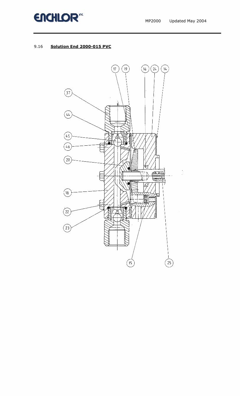
9.16 Solution End 2000-015 PVC

9.17 Solution End 2000-015 - PVC Parts List
ITEM PART NO DESCRIPTION QTY NOTES
14 10310 GASKET (ADAPTOR) 1 15 08/01/77 CAP SCREW (ADAPTOR) 4 16 07/01/26 OIL SEAL 1 17 S-094-4 DIAPHRAGM 1 18 S-080-4W PVC SOLUTION HEAD 1 19 S-099-4W SECONDARY PISTON 1 20 AS-096-4 PVC DIAPHRAGM BOLT ASSEMBLY 1 22 08/02/103 BOLT (SOLUTION HEAD) 6 23 09/01/28 WASHER (SOLUTION HEAD) 6 24 S-097-4W ADAPTOR 1 25 10/01/18 SPRING PIN 2 45 14/01/18 316SS BALL CHECKS 3/8" 2 14/01/19 HASTELLOY C BALL CHECKS 3/8" 2
14/01/21 CERAMIC BALL CHECKS 3/8" 2
KVD-4-S-PVC DISCHARGE VALVE ASSEMBLY 1
37 S-083-4W PVC VALVE BODY 1 44 S-088-4W PVC VALVE INSERT 1 46 07/03/44 'O'-RING 1 KVS-4-S-PVC SUCTION VALVE ASSEMBLY 1
37 S-083-4W PVC VALVE BODY 1 44 S-088-4W PVC VALVE INSERT 1 46 07/03/44 'O'-RING 1
Notes:
Recommended Spare Part
MP2000 Updated May 2004
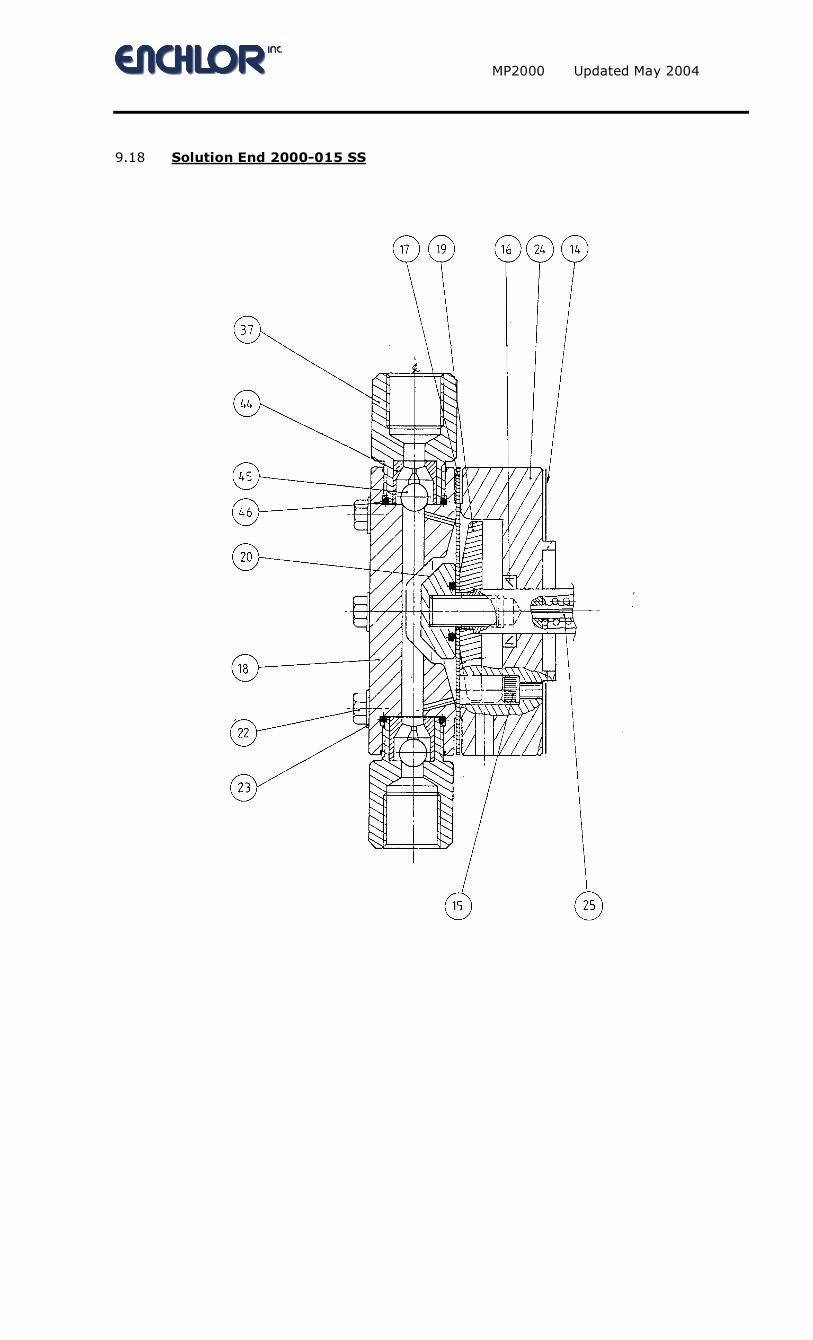
9.18 Solution End 2000-015 SS

9.19 Solution End 2000-015 - Stainless Steel Parts List
ITEM PART NO DESCRIPTION QTY NOTES
14 10310 GASKET (ADAPTOR) 1 15 08/01/77 CAP SCREW (ADAPTOR) 4 16 07/01/26 OIL SEAL 1 17 S-094-4 DIAPHRAGM 1 18 S-080-4W SS SOLUTION HEAD 1 19 S-099-4W SECONDARY PISTON 1 20 AS-096-4 SS DIAPHRAGM BOLT ASSEMBLY 1 22 08/02/103 BOLT (SOLUTION HEAD) 6 23 09/01/28 WASHER (SOLUTION HEAD) 6 24 S-097-4W ADAPTOR 1 25 10/01/18 SPRING PIN 2 45 14/01/18 316SS BALL CHECKS 3/8" 2 14/01/19 HASTELLOY C BALL CHECKS 3/8" 2
14/01/21 CERAMIC BALL CHECKS 3/8" 2
KVD-4-S-SS DISCHARGE VALVE ASSEMBLY 1
37 S-083-4W SS VALVE BODY 1 44 S-088-4W PTFE VALVE INSERT 1 46 07/03/44 'O'-RING 1 KVS-4-S-SS SUCTION VALVE ASSEMBLY 1
37 S-083-4W SS VALVE BODY 1 44 S-088-4W PTFE VALVE INSERT 1 46 07/03/44 'O'-RING 1
Notes:
Recommended Spare Part

MP2000 Updated May 2004
10. CALIBRATION OF A METERING PUMP To perform a calibration test on the delivery rate you will require a stop watch and materials necessary to perform a series of simple calculations. To utilise this system efficiently, the following procedure should be followed whilst the pump is operating.
1. Valve V1 must remain open except when the user is testing the deliver rate.
2. To test the delivery rate, open valve V2 and flood the calibration cylinder well above the top graduation mark.
3. Close valve V1.
4. At the moment when the fluid level reaches the top graduation mark, begin
timing the test.
5. When the liquid reaches the desired lower graduation, stop your watch and note down the time and calibration discharge quantity. Open valve V1 quickly and close V2 to avoid air being drawn into the system via the calibration cylinder.
6. Should another calibration test be required, then proceed to Item 2.
FIG. 1
EXAMPLE OF TYPICAL CALIBRATION TEST:
Test volume recorded : 1190 millilitres Test time taken : 63 seconds Flow Rate (L/H) = volume recorded (ml) x 3.6 time taken (sec) = 1190 x 3.6 = 68 litre/hour

CALIBRATION CYLINDER – INSTALLATION GUIDE
LOCATION: Install the calibration cylinder as shown in Figure 1. The cylinders must be installed in the suction piping in a vertical position and as close as possible to the suction tank. Remember the location should make allowance for sufficient free space around the calibration cylinder for easy reading of graduations. PIPING: It is essential that the size of the pipe to the calibration cylinder be the same size as the suction piping and cylinder inlet connection. Under-sized pipe work will cause suction losses and, hence, affect calibration accuracy. We strongly recommend that the use of full-flow ball valves to give consistent system throughput and rapid open and shut operation – an important feature when checking calibrations. Piping should be air-tight and suitably supported at regular intervals. An overflow/venting line should be connected between the top of the calibration cylinder and the supply tank.
CAUTION: NEVER USE THE CYLINDER ON THE DISCHARGE SIDE OF ANY PUMP.

MP2000 Updated May 2004
11. PULSATION VALVE INSTRUCTIONS INSTALLATION: We recommend installation of a pulsation dampener between valve and pump for both applications to provide smoother, more accurate valve operation and maximise valve life. Coat pipe fittings with suitable thread sealant such as PTFE tape before connecting to prevent leakage.
CAUTION: Do not over-tighten screwed connection. Should leakage occur during operation, unfasten connection and recoat threads with sealant.
ADJUSTMENT: Valve operating pressure is controlled by the spring (8) and can be increased or decreased by varying the spring preload. At date of purchase, Enchlor will adjust the valve to meet customer's requirements. To alter or set operating pressure at site, it is necessary for a pressure gauge with snubber to be installed in the line between the valve and the pump and with pump operating:- For Back Pressure: Unfasten locknut (5). Unscrew adjustment screw (4) to
decrease pressure or screw in to increase pressure. When required pressure is achieved, retighten locknut.
For Pressure Relief: Unfasten locknut. Unscrew adjustment screw to decrease
pressure or screw in to increase pressure. When full flow through valve at required relief pressure is achieved, retighten locknut.
MAINTENANCE: The valve and its components should be inspected annually or when incorrect operation is suspected. Disassembly is relatively simple. Unfasten locknut and unscrew adjustment screw to remove spring preload. Unfasten the three main bolts (3). These bolts hold the upper and lower halves together. Separate body halves and remove internals. Carefully inspect and clean all components. Worn or damaged parts should be replaced. Smear the outer surface of the plunger and the bore of the upper body with grease to prevent plunger sticking in bore during operation. Assembly procedure is reverse of disassembly. After reinstalling, adjust valve operating pressure as previously described.

INSTALLATION LAYOUT

MP2000 Updated May 2004