Embed Size (px)
Citation preview
E024S

WARNINGS• Important!Forthesafetyofpeople,itisimportantthatalltheinstructionsbecarefullyobserved.• Incorrectinstallationorincorrectuseoftheproductcouldcauseseriousharmtopeople.• Carefully read the instructions before beginning to install the product and keep them for future
reference.• Thesymbol indicatesnotesthatareimportantforthesafetyofpersonsandforthegoodcondition
oftheautomatedsystem.• Thesymbol drawsyourattentiontothenotesonthecharacteristicsandoperationoftheproduct.
CE DECLARATION OF CONFORMITY Manufacturer: FAACS.p.A.Address: ViaBenini,1-40069ZolaPredosaBOLOGNA-ITALYDeclares that: Controlboardmod.E024S,
•conformstotheessentialsafetyrequirementsofthefollowingEECdirectives:
2006/95/ECLowVoltageDirective 2004/108/ECElectromagneticCompatibilityDirective
Additionalinformation: Thisproductunderwentatestinatypical,uniformconfiguration. (allproductsmadebyFAACS.p.A)
Bologna01-03-2009. TheManagingDirector A.Marcellan
INDEX0 BOXLAYOUT.....................................................................................................................................2
1 WARNINGS.......................................................................................................................................3
2 LAYOUTANDCONNECTIONS............................................................................................................3
3 TECHNICALSPECIFICATIONS...........................................................................................................43.1 DESCRIPTIONOFCOMPONENTS........................................................................................................ 4
3.2 DESCRIPTIONOFTERMINAL-BOARDS................................................................................................. 4
4 PROGRAMMINGTHELOGIC.............................................................................................................4
5 PROGRAMMINGTHESPEED..............................................................................................................4
6. START-UP...........................................................................................................................................56.1 LEDSCHECK...................................................................................................................................... 5
6.2 PROGRAMMINGTHEDIPS-SWITCH..................................................................................................... 5
6.3 TIME-SETUPLEARNING..................................................................................................................... 5
6.3.1 AUTOMATICSET-UP................................................................................................................................................56.3.2 MANUALSET-UP.....................................................................................................................................................56.3.3 PROGRAMMINGOFTHELOGIC............................................................................................................................66.3.4 SECONDLEvELPROGRAMMING-ADvANCEDFUNCTIONS....................................................................................6
7 INSTALLATIONOFBUSACCESSORIES................................................................................................77.1 ADDRESSINGTHEBUSPHOTOCELLS.................................................................................................. 7
7.2 MEMORYSTORAGEOFBUSACCESSORIES....................................................................................... 8
8 MEMORYSTORINGTHERADIOCODE...............................................................................................88.1 MEMORYSTORAGEOFDSRADIOCONTROLS................................................................................... 8
8.2 MEMORYSTORAGEOFSLHRADIOCONTROLS.................................................................................. 8
8.3 MEMORYSTORAGEOFLCRADIOCONTROLS................................................................................... 9
8.3.1REMOTEMEMORYSTORAGEOFLCRADIOCONTROLS..................................................98.4 RADIOCONTROLSDELETIONPROCEDURE........................................................................................ 9
9 CONNECTIONOFBUFFERBATTERIES(OPTIONAL)..............................................................................9
10 AUTOMATEDSYSTEMTEST.................................................................................................................9
11 S700HADDRESSINGBUSENCODER...............................................................................................10
12 LOGICTABLES.................................................................................................................................10
EN
GLIS
H
�
a
a cb
c
306
225
Fig.B Fig.F
Fig.C
Fig.D
Fig.E
230v->2,5A-250v115v->4A-120v
Fig.A
130
64
0 BOXLAYOUT
Fig.Bshowsthefour5mmdiam.holesforsecuringthebox(ref.a)tothewall,thethreefittingsM16/M20/M25forinstallingthecablegrippers(ref.b)andthetwolidhinges(ref.c).
THE bOX CONTAINS THE E024S ELECTRONIC uNIT AND THE DEvICES TO pOWER IT. IT MuST THEREFORE bE HAN-DLED WITH CARE DuRING ALL INSTALLATION STAGES, TO AvOID DAMAGING ITS COMpONENTS.
ThedimensionsoftheboxareshowninFig.A:
Thelidhingescanbemovedupwardtoallowopeningtheboxhousing(Fig.C);theycanalsoberemovedandre-positionedinordertoenablethelidtoopentotherightorleft.
Whenyouhavesecuredtheboxintheselectedposition,coverthesecuringholes(ref.a Fig.B)andthescrewswiththesuppliedplugsasshowninFig.D.
Afteryouhavefinishedtheoperationstoconnectthecontrolboardwiththevariouspartsoftheautomatedsystem,closethebox,positioningthelidinitsseatwithseal.ConnectthesupplyasshowninFig.E.
Dimensions in mm
ELECTRICAL bOX E024S
Next,tightenthefoursuppliedscrewstoguaranteethedegreeofprotectionagainstexternalagents(Fig.F).
EN
GLIS
H
2

2
Fig. 1Fig. 1
1 WARNINGS
before attempting any work on the control unit (connections, maintenance), always turn off power.- Install, upstream of the system, a differential thermal breaker with adequate tripping threshold,- Always separate power cables from control and safety cables (push-button, receiver, photocells, etc.).- To avoid any electrical disturbance, use separate sheaths or a screened cable (with the screen earthed).
CONTROL uNIT E024S
2 LAYOUTANDCONNECTIONS
(PARTIALOPENING)
(TOTALOPENING)
230 vAC 50Hzor
��5 vac 60Hz *�
*� THE pOWER SuppLY IS RELATED TO THE E024S puRCHASED vERSION.
EN
GLIS
H
3

3 TECHNICALSPECIFICATIONS
power supply voltage *2 230Vac(+6%-10%)-50Hzor
115Vac(+6%-10%)-60Hz
Absorbed power 4W
Motor max. load 150Wx2
Accessories max. current (+24v)
250mA
buS Accessories max.current 400mA
Operating ambient tempera-ture
-20°C...+55°C
Fuses *2 F1=self-resetting;F2=T2A-250VorT4A-120V
Function logics A,E,AP,EP,A1,B,C
Work time (time-out) 5minute(fixed)
pause timeVariesaccordingtolearning
(max.10min.)
Terminal board inputsOpenA,OpenB,Stop,BUS
(I/O)
Connector inputsPowersupply,battery
moduleXF433orXF868
Terminal board outputs
Motors,flashinglamp,powersupplytoaccessories,
electriclock,servicelightcontact(90secfixed)
programmable functionsLogic(A,E,AP,EP,A1,B,C),
Speed(High-Low)
Learning functions Pausetime,leafclosingdelay
Integrated radio channels type
DS,SLH(max250channels)LC(max250channels-
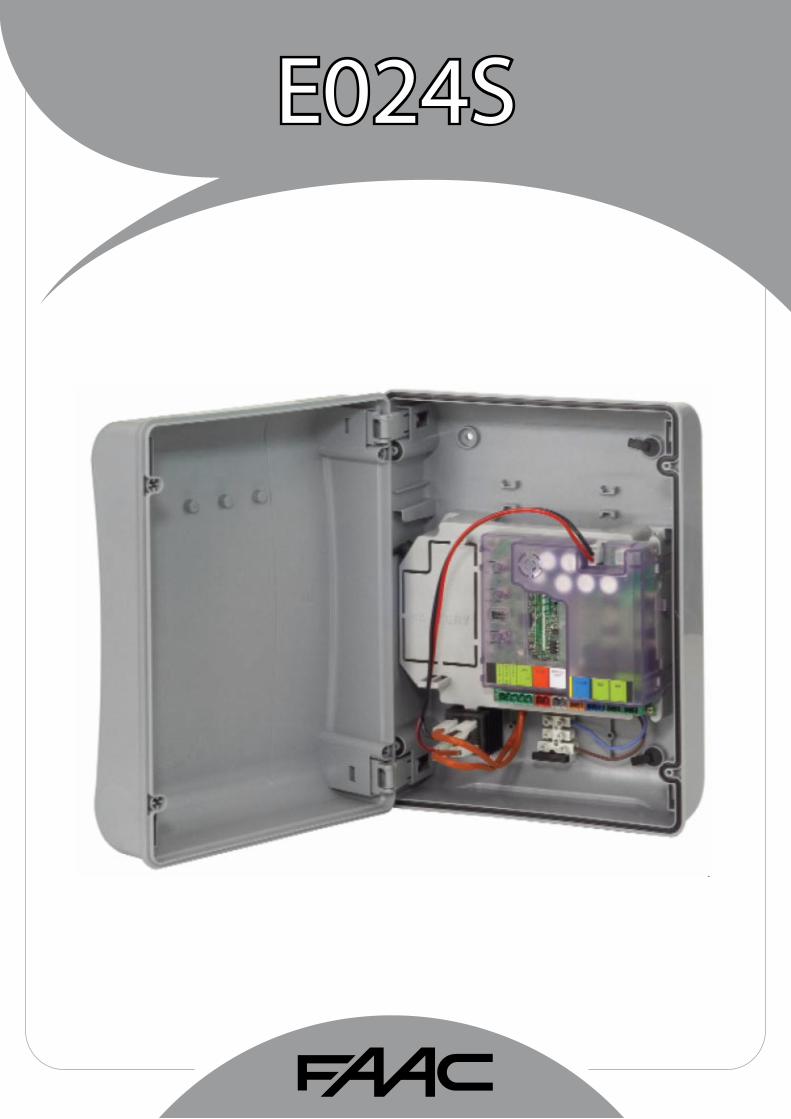
J1 POWERSUPPLYconnector
J2 SERVICELIGHTcommandterminal-board
J3 FLASHINGLAMPterminal-board
J4 ELECTRICLOCKterminal-board
J5 COMMANDSterminal-board
J7 MOTOR1terminal-board
J8 MOTOR2terminal-board
J9 RapidconnectionforXFMODULE
J10 BUSterminal-board
J11 BATTERYconnector
SW1 SETUPpush-button
SW2 SPEEDpush-button
SW3 LOGICpush-button
DS1 ProgrammingDip-switch
F1 Accessoriesprotectivefuse
F2 Fusesprotectingtransformersandmotors
LED SignallingLEDs
3.1 DESCRIPTIONOFCOMPONENTS
Terminal and/or terminal-board Description Device connected
1
J5
+24V Powersupplyforaccessories
2 GND Negative
3 STOPDevicewithNCcontactwhichcausestheautomatedsystemtoshutdown
4 OPENB DevicewithN.Ocontact(seechap.FUNCTIONLOGICS)5 OPENA
J10REDterminal
BUS SafetydeviceswithBUStechnology
J2GREYterminal
SERVICELIGHT
ServiceLightcontroloutput(connectarelaycoilat24Vdc-100mAmax)
J3ORANGEterminal LAMP Flashinglamp24Vdc
-15W
J4BLUEterminal LOCK
Electriclock12Vacor24Vdc(tobeinstalledonleaf1)
J7 MOT1 Motor1(leaf1)
J8 MOT2 Motor2(leaf2)
3.2 DESCRIPTIONOFTERMINAL-BOARDS
5 PROGRAMMINGTHESPEEDThefunctionSPEEDcanbeadjustedatanytimebypressingpush-buttonSW2.TheselectedspeedisthendisplayedonLEDLD8:
LEDon =HIGHspeed LEDoff =LOWspeed
Leaf1meanstheleafwhichopensfirstduringtheopeningoperation.
The service light control is active during theentiregateopeningorclosingmovementandforthesuccessive90seconds.
*2 Thepowersupplyandthefusearerelatedtothepurchasedversion.
3.3 ANTI-CRUSHINGFUNCTIONTheelectronicanti-crushingfunctionisobtainedbycontrollingthecurrentconsumptionortheencoderofthemotorscon-nectedtotheE024Sequipment.Ifthegatedetectsanobstacleduringtheopeningorclosingmovement,theanti-crushingfunctionactivatesandreversesthesenseofdirectionoftheoperator,thusincreasingthesafetydegreeoftheautomatedsystem.
4 PROGRAMMINGOFTHELOGICRepeatedlypresstheSW3LOGICpush-buttontoselectoneofthe7programminglogicsavailable.TheselectedlogicissignaledbytheLD7LED:thenumberofblinkingscorrespondstothenumberoftheselectedlogic.See paragraph 6.3.3.
EN
GLIS
H
4

6.3 TIME-SETUPLEARNING
Before any manoeuvre is executed, a SETUPcyclemustfirstberun.
IfthemotortypeischangedwiththeDS3andDS4dip-switchesaftertheSETUP,anewSETUPisrequested.
WhentheboardispoweredupandaSETUPcyclehasneverbeenexecuted,LEDsLD4andLD5begintoflashslowlytosignalthataSETUPcyclemustbeexecuted.There are two possible types of SETUP: AUTOMATIC andMANUAL
LED ON (closed contact) OFF (open contact)
STOP Command disabled Commandenabled
OPENA Commandenabled Command disabled
OPENB Commandenabled Command disabled
BUS Seepar.7.2
6 START-UP6.1 LEDSCHECK
ThefollowingtableshowsthatstatusoftheLEDsinrelationtothestatusoftheinputs(theclosedatrestautomatedsystemconditionisshowninbold).CheckthestatusofthesignallingLEDsaspertablebelow:
Tab.1–OperationofinputsstatusLEDs
6.2 PROGRAMMINGTHEDIPS-SWITCH
DS� DS2 DS3 DS4 Description
OFF OFF LOW FORCE
OFF ON MEDIUM-LOWFORCE
ON OFF MEDIUM-HIGHFORCE
ON ON HIGHFORCE
OFF OFF MOTOR 39�
OFF ON MOTOR418
ON OFF MOTOR413-415-390-770
ON ON HYDRAULICMOTOR(*)S450H/S700H
ThesettingsoftheDS1dip-switchforprogrammingtheforceandthetypeofmotorareshowninthefollowingtable.
Tab. 2 - DS� programming
(default settings in bold)
(*)IfDS3-DS4aresettoON,duringthesetupphasetheEncS700orEncS450encoderauto-maticallyrecognizestheS700HorS450Hcon-nectedoperator.
BeforeperformingtheSetup,selecttheopera-torconnectedtotheE024SequipmentwiththeDS1(DS3-DS4)DIPswitches.
6.2.1PRELIMINARYPHASEOFAUTOMATICORMANUALSETUP
TheAutomaticorManualSETUPphaseisprecededbyaninitiali-sationphase:bypressingtheSETUPpush-buttonforautomaticormanualsetup,theleavesopen,oneatatimeandfromanyposition,untilanobstacleoranOpenimpulseisdetected.Thentheleavesstartclosing,oneatatime,untilanobstacleoranOpenimpulseisdetected.Thentheproceduredescribedinparagraph6.3.1orparagraph6.3.2starts.At theendofasuccessfulSETUPprocedure theLEDsswitchoff.Otherwise,theprocedureendswiththerequestofanewSETUPsignaledbyblinkingLEDs.
6.3.1 AUTOMATICSETUP
ToenterinAutomaticsetup,presstheSETUPpush-buttonuntilthetwoLD4andLD5LEDsarepermanentlylit.ThenreleasetheSETUPpush-button.
DuringtheSetupphasebothLEDsblink.
TheSetupphase isprecededbyapreliminaryphase,6.2.1.
Thentheleavesstartmoving,oneatatime,fromtheclosedposition.
Onceanopeningstoporan"open"impulseisdetected,theyreachtheopenpositionandthesetupisended.
Slow-downscannotbeset.
Thepausetimeisfixedat30s.
OncetheSETUPprocedureisstarted,switchthemotorsupplycablesiftheleavescloseinsteadofopening.
With the AUTOMATIC SETUP, the slow-downspaces,theclosingleafdelaysandthepausetime(30s,withA logic)aredefinedduringtheSetupphase.Tochangetheopening/clos-ingleafdelayandthepausetime,usethesecondlevelmenu.
1.
6.3.2 MANUALSETUP
ToenterinManualsetup,presstheSETUPpush-buttonuntilthetwoLD4andLD5LEDsarepermanentlylit.Keepitpresseduntiltheautomatedsystemstartsmovingautomatically.
DuringtheSetupphasebothLEDsblink.
The Setup phase is preceded by a preliminary phase,6.2.1.
Thentheleavesstartmoving,oneatatime,fromtheclosedpositionwithan"open"commandorautomatically.
Open impulse ---> slowdown from leaf opening 1. If astopisdetected,anopeningstopsearchisset.IfOpenisdetected,astopinthestoredopenpositionisset.Startingfromleafopening2.
1.
2.
EN
GLIS
H
5

6.3.4 SECONDLEvELPROGRAMMING-ADvANCEDFUNCTIONS
Toenterthesecondlevelmenu,keeptheSW2SPEEDpush-buttonpressedformorethe2.5seconds.ThetwoSETUPLEDsarepermanentlylit.Inthismode,theSPEEDpush-buttonisusedtoscrollthemenus.Thedifferentmenusareidentifiedbythenumberofblinkings.Theparametervalue issetwith theLOGICpush-button.Themenu is scrolled sequentially. Keep the SPEED push-buttonpressedfor2.5secondstoexitthesecondlevelmenu.
Menu1Wind-prooffacility1SW2pressedonce LD8blinkingonce
Wind-prooffacilityNOLD7LEDOFF
Wind-prooffacilityYESLD7LEDON
Menu2Reverse StrokeSW2pressedtwice LD8blinkingtwice
ReverseStrokeNOLD7LEDOFF
ReverseStrokeYES LD7LEDON
Menu3Soft-touch SW2pressedthreetimes LD8blinkingthreetimes
Soft-touchNOLD7LEDOFF
Soft-touchYESLD7LEDON
Menu4PreliminaryblinkingSW2pressedfourtimes LD8blinkingfourtimes
PreliminaryblinkingNOLD7LEDOFF PreliminaryblinkingYESLD7LEDON
Menu5Leaf opening delaySW2pressedfivetimes LD8blinkingfivetimes LeafopeningdelayNOLD7 LEDOFF LeafopeningdelayYESLD7 LEDON
Menu6Leaf closing delaySW2pressedsixtimes LD8blinkingsixtimes Leafclosingdelay-- LD7LEDOFF Leafclosingdelay,count LD7LEDON
Menu7PausetimeSW2pressedseventimes LD8blinkingseventimes Pausetime-- LD7LEDOFF Pausetime,countLD7LEDON
With menus 6 and 7, keep the LOGIC push-buttonpresseduntilreachingthetimetobeset.The t ime can be set between 0 and4.25minutes.
6.3.3PROGRAMMINGOFTHELOGIC
RepeatedlypresstheSW3push-buttontoselectoneofthe7programminglogicsavailable.TheselectedlogicissignaledbytheLD7LED.Thenumberofblinkingscorrespondstothenumberoftheselectedlogic:
Logic A (Automatic)SW3pressedonce-LD7blinkingonceLogic E (Semi-automatic)SW3pressedtwice-LD7blinkingtwiceLogic Ap ("Stepped" automatic)SW3pressedthreetimes-LD7blinkingthreetimesLogic Ep ("Stepped" semi-automatic)SW3pressedfourtimes-LD7blinkingfourtimesLogic A�(Automatic �) SW3pressedfivetimes-LD7blinkingfivetimesLogic b (Semi-automatic “b”) SW3pressedsixtimes-LD7blinkingsixtimesLogic C (Dead man)SW3pressedseventimes-LD7blinkingseventimes
3.Openimpulse--->slowdownfromleafopening2.Ifastopisdetected,anopeningstopsearchisset.IfOpenisdetected,astopinthestoredopenpositionisset.
4.Fromnowuntil thenextOpen impulse, thepause time iscounted.
5.Open impulse --->Pause timeacquisitionandstart fromleafclosing2.
6.Openimpulse--->Slowdownfromleafclosing2.Ifastopisdetected,anclosingstopsearchisset.IfOpenisdetected,a stop in closed position is set (only with absolute encoderEnc450).
7.Startingfromleafclosing1.
8.Openimpulse--->slowdownfromleafclosing1.Ifastopisdetected,anclosingstopsearchisset.IfOpenisdetected,a stop in closed position is set (only with absolute encoderEnc450).
OncetheSETUPprocedureisstarted,switchthemotorsupplycablesiftheleavescloseinsteadofopening.
WiththeMANUALSETUPtheslow-downspacesand the leafclosingdelaysareset fromtheboardduringtheSetupphase.Asanalterna-tive, the leaf opening/closing delay and thepausetimecanbechangedinthesecondlevelprogrammingwithoutrepeatingtheSetup.
EN
GLIS
H
6

Fig.2
7 INSTALLATIONOFBUSACCESSORIES
Thisboard is suppliedwithaBUScircuitenablingeasycon-nectionofahighnumberofBUSaccessories (e.g.upto16photocellspairs),appropriatelyprogrammed,usingonlytwocablewithoutpolarity.Belowwedescribe theaddressingandmemory storageoftheBUSphotocells.Forotherfutureaccessories,refertothespecificinstructions.
7.1 ADDRESSINGTHEBUSPHOTOCELLS
Important:thesameaddressmustbegiventobothtransmitterandreceiver.
Make sure that there are no two or morephotocellspairswiththesameaddress.
IfnoBUSaccessoryisused,leavetheBUScon-nectorfree(J10-fig.1).
Amaximumof16BUSphotocellpairscanbeconnectedtotheboard.Thephotocellsaresplitintogroups:
Openingphotocells: max6Closingphotocells: max7Opening/Closingphotocells: max2PhotocellusedasanOPENpulse: max1
Dip1 Dip2 Dip3 Dip4 Ref. Type
OFF OFF OFF OFF
B-C OPENING
OFF OFF OFF ON
OFF OFF ON OFF
OFF OFF ON ON
OFF ON ON OFF
OFF ON ON ON
ON OFF OFF OFF
D CLOSING
ON OFF OFF ON
ON OFF ON OFF
ON OFF ON ON
ON ON OFF OFF
ON ON OFF ON
ON ON ON OFF
OFF ON OFF OFFA OPENINGand
CLOSINGOFF ON OFF ON
ON ON ON ON / OPENPULSE
Tab. 3 - Addressing of buS photocells
Table3showstheprogrammingoperationsofthedip-switchinsidethetransmitterandoftheBUSPhotocellsreceiver.
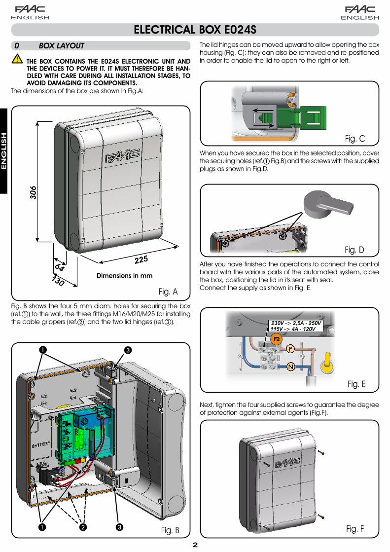
Fig.2showsa2-swingleafautomatedsystemindicatingthecoveragebeamsofthephotocells:
A: PhotocellswithOPENINGandCLOSINGaction.
B: PhotocellswithOPENINGaction
C: PhotocellswithOPENINGaction
D: PhotocellswithCLOSINGaction
6.3.5 RETURNTODEFAULTSETTINGS
Restorethedefaultsettingsasfollows:KeeptheSETUPpush-buttonpressedtoswitchtheboardON.The two SETUP LEDs are alternately lit ("level crossing"mode).Theboardresetstheparameters.Until the SETUP push-button is pressed, movements areinhibited.WhentheSETUPpush-buttonisreleased,thetwoLD4andLD5LEDsblink.ThedefaultconfigurationisresetandthenewSetupcanbestarted.
1.
2.
3.4.
5.
6.
6.3.6 DEFAULTPARAMETERS
Herethedefaultparameters:
-Logic:A-Wind-prooffacility:NO-ReverseStroke:NO-Soft-touch:NO-Preliminaryblinking:NO-Leafopeningdelay:YES-Leafclosingdelay:10s-Pausetime:30s
EN
GLIS
H
�

Fig.3
a
8 MEMORYSTORINGTHERADIOCODE
The control board has an integrated 2-channel decodingsystem(DS,SLH,LC)namedOMNIDEC.Thissystemmakes itpossible tomemory-storeboth totalopening (OPENA)andpartialopeningOPENB)oftheautomatedsystem-thisismadepossiblebyanadditionalreceivermodule(fig.3ref.a)andradiocontrolsonthesamefrequency.
The3typesofradiocodes(DS,LSH,LC)cannotcoexist.
Onlyoneradiocodecanbeusedatatime.Tochangeoverfromonecodetoanother,youmustdeletetheexistingone(seeparagraphondeletion),andrepeatthememory-storageprocedure.
8.1 MEMORYSTORAGEOFDSRADIOCONTROLS
Amaximumoftwocodescanbestored.OneontheOPENAchannelandoneontheOPENBchannel.
On the DS radio control, select the required ON-OFFcombinationforthe12dip-switches.Press the LOGIC (SW3) or SPEED (SW2) push-button, tomemorystorerespectivelytotalopening(OPENA)orpartialopening(OPENB),andasyouholditdown,alsopresstheSETUP (SW1)push-button. The relevant LED starts to flashslowlyfor5sec..Releasebothpush-buttons.Withinthese5sec.,presstheappropriatepush-buttonontheradiocontrol.TherelevantLEDlightsuponsteadybeamfor1secondandthengoesOFF,indicatingthatstoragewasexecuted.To add other radio controls, set the same ON - OFFcombinationusedinpoint1.
8.2 MEMORYSTORAGEOFSLHRADIOCONTROLS
A maximum of 250 codes can be memorystored,splitbetweenOPENAandOPENB.
OntheSLH radiocontrol, simultaneouslypressandholddownpush-buttonsP1andP2.TheradiocontrolLEDbeginstoflash.Releasebothpush-buttons.Press the LOGIC (SW3) or SPEED (SW2) push-button, tomemorystorerespectivelytotalopening(OPENA)orpartialopening(OPENB),andasyouholditdown,alsopresstheSETUP (SW1)push-button. The relevant LED starts to flashslowlyfor5sec.Releasebothpush-buttons.Withinthese5sec.,whiletheradiocontrolLEDisstillflashing,pressandholddowntherequiredpush-buttonontheradiocontrol(theradiocontrolLEDlightsuponsteadybeam).The LED on the board lights up on steady beam for 1secondandthengoesOFF, indicatingthatstoragewasexecuted.Releasetheradiocontrolpush-button.
1.
2.
3.4.
5.
6.
1.
2.3.4.
5.6.
7.
8.
7.2 MEMORYSTORAGEOFBUSACCESSORIES
Youcanadd theBUSphotocells to thesystematany time,simplybymemory-storingthemontheboard,observingthefollowingprocedure:
Install and program the accessories using the requiredaddress(seeparagraph7.1)Cutpowertotheboard.Connectthetwoaccessoriescablestotheredterminal-boardJ10(anypolaritywilldo).Power up the board, taking care to first connect themain power supply (transformer output) and then anybatteries.Quicklypressonceonly theSW1 (SETUP)push-button, toexecutelearning.TheBUSLEDflashes.Give an OPEN impulse, leaves will move and the BUSlearningprocedureisover.
TheboardhasmemorystoredtheBUSaccessories.FollowtheinstructionsinthetablebelowtocheckiftheBUSconnectioniscorrect.
Tab. 4 - Description of buS LED
Steady lightNormal operation (LED ON even in theabsenceofphotocells)
Slow flashing lamp (flashevery0.5sec)
At least one input engaged: photocellengagedornotaligned,OpenAorOpenBorStopinputengaged
Light OFF(flashevery2.5sec)
BUSlineshortcircuited
Fast flashing lamp (flashevery0.2sec)
If you have detected a BUS connectionerror,repeattheacquisitionprocedure.Iftheerrorisrepeated,makesurethatthereisnotmorethanoneaccessorywiththesameaddressinthesystem(alsoseetheaccessoriesinstructions)
1.
2.3.
4.
5.
6.
EN
GLIS
H
�

a
Fig.10
Fig.11
10MM
16MM +16MM
10 AUTOMATEDSYSTEMTESTWhenyouhavefinishedprogramming,checkifthesystemisoperatingcorrectly. Inparticular,checkifthesafetydevicesareoperatingcorrectly.
8.3.1 REMOTEMEMORYSTORAGEOFRCRADIOCONTROLS
OtherradiocontrolscanberemotelystoredonlywiththeRCradiocontrols,i.e.withoutusingtheLOGIC-SPEED-SETUPpush-buttons,butusingapreviouslystoredradiocontrol.
Getaradiocontrolalreadystoredononeofthe2channels(OPENAorOPENB).Pressandholddownpush-buttonsP1andP2simultaneouslyuntilboththeLEDsflashslowlyfor5sec.Within 5 sec. press the push-button of the radio controlthathadbeenmemorystoredtoenablelearningontheselectedchannel.
1.
2.
3.
Quicklypresstwicethememorystoredradiocontrolpush-button.
Theautomatedsystemperformsoneopeningoperation. Make sure that the automatedsystem is free of any obstacle created bypersonsorthings.
Toaddotherradiocontrols,transferthecodeofthememory-storedpush-buttonoftheradiocontroltotherelevantpush-button of the radio controls to be added, observing thefollowingprocedure.
Onthememorystoredradiocontrol,simultaneouslypressandholddownpush-buttonsP1andP2.TheradiocontrolLEDbeginstoflash.Releasebothpush-buttons.Pressthememorystoredpush-buttonandholditdown(theradiocontrolLEDlightsuponsteadybeam).Bringtheradiocontrolsnear,pressandholddownthepush-buttonoftheradiocontroltobeadded,releasingitonlyafter thedouble flashof the radiocontrol LED,whichindicatesmemorystorageexecuted.Quicklypresstwicethepush-buttonofthememorystoredradiocontrol.
Theautomatedsystemperformsoneopeningoperation. Make sure that the automatedsystem is free of any obstacle created bypersonsorthings.
8.3MEMORYSTORAGEOFRCRADIOCONTROLS
A maximum of 250 codes can be memorystored,splitbetweenOPENAandOPENB.
UseRCremotecontrolsonlywithreceivermoduleat433MHz.Press the LOGIC (SW3) or SPEED (SW2) push-button, tomemorystorerespectivelytotalopening(OPENA)orpartialopening(OPENB),andasyouholditdown,alsopresstheSETUP (SW1)push-button. The relevant LED starts to flashslowlyfor5sec.Releasebothpush-buttons.Withinthese5sec.,presstheappropriatepush-buttonontheRCremotecontrol.TheLEDlightsuponsteadybeamfor1second,indicatingmemorystorageexecuted,andthenresumesflashingforanother5sec.,duringwhichanotherradiocontrol(point4)canbememorystored.Whenthe5sec.haveelapsed,theLEDgoesOFFindicatingtheendoftheprocedure.Toaddotherradiocontrols,repeattheoperationatpoint1.
9.
•
•••
•
•
1.
2.
3.
4.
5.
6.
TheLEDontheboardrelatingtothechannelbeinglearnedflashesfor5sec.,withinwhichtimethecodeofanotherradiocontrolmustbetransmitted.TheLEDlightsuponsteadybeamfor2seconds,indicatingmemorystorageexecuted,andthenresumesflashingfor5sec.,duringwhichotherradiocontrolscanbememorystored,andthengoesOFF.
8.4 RADIOCONTROLSDELETIONPROCEDURE
TodeleteALL the input radiocontrolcodes,presspush-buttonLOGIC(SW3)orSPEED(SW2)and,whileholding itdown,alsopresspush-buttonSETUP(SW1)for10sec.The LED relating to the pressed push-button flashes forthefirst5sec,andthenflashesmorequicklyforthenext5sec.BothLEDslightuponsteadybeamfor2secandthengoOFF(deletioncompleted).Releasebothpush-buttons.
This operation is NOT reversible. All codes ofradiocontrolsstoredasOPENAandOPENBwillbedeleted.
4.
5.
1.
2.
3.
4.
9 BATTERYKIT(OPZIONAL)Thebufferbatterykitwasbuilt for insertion inside thecontrolboardsupport.This support (Fig.10 ref.a) was pre-moulded to permit thebatteryhousingtobeopened.
Remove the board support material covering thebatteryhousing,cutting thematerialconnectionsalongtheperimeter.
1.
Insertthebatteryinthehousingyouhavejustcreated,andsecureitontheanchoringsupports(Fig.11).
2.
To correctly fasten and connect the kit to the controlunit, consult the inst ruct ions enclosed with thebatterykit.
3.
EN
GLIS
H
9

LOGIC “A” puLSES
AuTOMATED SYSTEM STATuS OpEN A OpEN b STOp FSW Op FSW CL FSW CL/Op
CLOSED opensandclosesafterpausetime
opensreleasedleafandclosesafterpausetime
noeffect(OPENdisabled)
noeffect(OPENdisabled) noeffect noeffect
(OPENdisabled)
OpENING noeffect(1) noeffect stopsoperation reversesatclo-sure noeffect
stopsandopensatrelease(saves
CLOSE)
OpEN IN pAuSE rechargespausetime(1)
rechargespausetimeofreleasedleaf
stopsoperation noeffectrechargespausetime
(CLOSEdisabled)
rechargespausetime
(CLOSEdisabled)
CLOSING reopensleavesimmediately
reopensleavesimmediately stopsoperation noeffect reversesatopening
stopsandopensatrelease(saves
CLOSE)
bLOCKED closesleaves closesleavesnoeffect
(OPEN/CLOSEdisabled)
noeffect(OPENdisabled)
noeffect(CLOSEdisabled)
noeffect(OPEN/CLOSE
disabled)
Tab. 5
(1)ifthecyclebeganwithOPEN-B(releasedleaf),bothleavesareactivatedatopening
12 FUNCTIONLOGICS
Connectionof theBUS input to thecontrolboard is via thebipolarcableswhichcomeoutoftheencoders.unlike the case of the photocell devices, the polarity of the buS line connection determines whether the encoder belongs to one leaf rather then the other.ThisiswhyyoumustpaygreatattentiontotheindicationsofthestatusLEDsonthebodyofeachencoder(Fig.1).
BelowwelistthefunctionsofLEDsLD1,DL2,andDL3,andtheirstatuses:TAb. � - Encoder connection and LED status
LED LIGHTED FLASHING OFF
DL1
PowerONandBUS
communicatingwithboard
PowerONbutBUSnot
communicating
NoPowerorBUScommunication
DL2 Leaf1encoder / Leaf2encoder
DL3 Leafnotmoving
Pulsesreadwhileleafmoving
Leafnotmoving
11S700H:ADDRESSINGBUSENCODER
DL � mustalwaysbelightedtoguaranteecorrectconnectionbetweenencoderandboard.DL 2 determinestheleafonwhichtheencoderisinstalled.Providingtheconfigurationiscorrect,theautomatedsystemwillshow:anencoderwithDL2lightedintheleaf1,andanencoderwithDL2OFFintheleaf2.Ifthereisanincorrectconnection, i.e. indicating twoencoderswith the samestatusoftheDL2LEDs,duringthelearningprocedureoftheBUSaccessories,theDL1LEDsofbothencodersshowtheFLASHINGstatus.Inthissituation,refertotheconfigurationinTAB.3todefinewhichencoderconnectiontorotate.DL 3 indicates,onasteadyflashingbeam,thereadingof the pulses while the leaf is moving. When the leaf ismotionless,DL3canbeeitherlightedorOFF.
N.B.inparticularmotionlessleafpositions,DL3mayflutterconsiderably.Thissignalmustnotbeconsideredafault.
•
•
•
•
LEAF1 LEAF2
LEAF2 LEAF1
OFF
ON
DL1
DL3DL2
Fig.�
DL1
DL3DL2DL1
DL1
DL3DL2
DL3 DL2
ON
OFF
EN
GLIS
H
�0

Tab. �
(1)ifthecyclebeganwithOPEN-B(releasedleaf),bothleavesareactivatedatopening
LOGIC “Ep” puLSES
AuTOMATED SYSTEM STATuS OpEN A OpEN b STOp FSW Op FSW CL FSW CL/Op
CLOSED openstheleaves opensreleasedleaf
noeffect(OPENdisabled)
noeffect(OPENdisabled) noeffect noeffect
(OPENdisabled)
OpENING stopsoperation(1) stopsoperation stopsoperation
immediatelyreversesatclo-
surenoeffect
stopsandopensatrelease
(OPENstops-savesCLOSE)
OpEN reclosesleavesimmediately(1)
reclosesleavesimmediately
noeffect(OPEN/CLOSE
disabled)noeffect noeffect
(CLOSEdisabled)
noeffect(OPEN/CLOSE
disabled)
CLOSING stopsoperation stopsoperation stopsoperation noeffect reversesatopening
stopsandopensatrelease
(OPENstops-savesCLOSE)
bLOCKED
restartsmovinginoppositedirection.Alwaysclosesafter
STOP
restartsmovinginoppositedirection.Alwaysclosesafter
STOP
noeffect(OPEN/CLOSE
disabled)
noeffect(OPENdisabled)
noeffect(CLOSEdisabled)
noeffect(OPENstops-savesCLOSE)
Tab. 6
Tab. �
LOGIC “E” puLSES
AuTOMATED SYSTEM STATuS OpEN A OpEN b STOp FSW Op FSW CL FSW CL/Op
CLOSED openstheleaves opensreleasedleaf
noeffect(OPENdisabled)
noeffect(OPENdisabled) noeffect noeffect
(OPENdisabled)
OpENING stopsoperation(1) stopsoperation stopsoperation
immediatelyreversesatclo-
surenoeffect
stopsandopensatrelease(OPENstops
-savesCLOSE)
OpENrerecloses
leaves immediately(1)
rereclosesleavesimmediately
noeffect(OPEN/CLOSE
disabled)noeffect noeffect
(CLOSEdisabled)
noeffect(OPEN/CLOSE
disabled)
CLOSING reopensleavesimmediately
reopensleavesimmediately stopsoperation noeffect reversesatopening
stopsandopensatrelease(OPENstops
-savesCLOSE)
bLOCKED closesleaves closesleavesnoeffect
(OPEN/CLOSEdisabled)
noeffect(OPENdisabled)
noeffect(CLOSEdisabled)
noeffect(OPENstops-savesCLOSE)
(1)ifthecyclebeganwithOPEN-B(releasedleaf),bothleavesareactivatedatopening
(1)ifthecyclebeganwithOPEN-B(releasedleaf),bothleavesareactivatedatopening
LOGIC “Ap” puLSES
AuTOMATED SYSTEM STATuS OpEN A OpEN b STOp FSW Op FSW CL FSW CL/Op
CLOSED opensandclosesafterpausetime
opensreleasedleafandclosesafterpausetime
noeffect(OPENdisabled)
noeffect(OPENdisabled) noeffect noeffect
(OPENdisabled)
OpENING stopsoperation(1) stopsoperation stopsoperation
reversesatclosure(saves
OPEN)noeffect
stopsandopensatrelease
(OPENstops-savesCLOSE)
OpEN IN pAuSE stopsoperation(1) stopsoperation stopsoperation noeffect
rechargespausetime
(CLOSEdisabled)
rechargespausetime
(CLOSEdisabled)
CLOSING reopensleavesimmediately
reopensleavesimmediately stopsoperation noeffect reversesatopening
stopsandopensatrelease
(OPENstops-savesCLOSE)
bLOCKED closesleaves closesleavesnoeffect
(OPEN/CLOSEdisabled)
noeffect(OPENdisabled)
noeffect(CLOSEdisabled)
noeffect(OPEN/CLOSE
disabled)
EN
GLIS
H
��

Tab. ��
LOGIC “C” MAINTAINED COMMANDS puLSES
AuTOMATED SYSTEM STATuS OpEN A OpEN b STOp FSW Op FSW CL FSW CL/Op
CLOSED openstheleaves noeffect noeffect(OPENdisabled)
noeffect(OPENdisabled) noeffect noeffect
(OPENdisabled)
OpENING noeffect closesleaves stopsoperation locksoperation noeffect locksoperation
OpEN noeffect closesleavesnoeffect
(OPEN/CLOSEdisabled)
noeffect noeffect(CLOSEdisabled)
noeffect(OPEN/CLOSE
disabled)
CLOSING openstheleaves noeffect stopsoperation noeffect locksoperation locksoperation
bLOCKED openstheleaves closesleavesnoeffect
(OPEN/CLOSEdisabled)
noeffect(OPENdisabled)
noeffect(CLOSEdisabled)
noeffect(OPEN/CLOSE
disabled)
(1)ifthecyclebeganwithOPEN-B(releasedleaf),bothleavesareactivatedatopening
Tab. 9
LOGIC “A�” puLSES
AuTOMATED SYSTEM STATuS OpEN A OpEN b STOp FSW Op FSW CL FSW CL/Op
CLOSED opensandclosesafterpausetime
opensreleasedleafandclosesafterpausetime
noeffect(OPENdisabled)
noeffect(OPENdisabled) noeffect noeffect
(OPENdisabled)
OpENING noeffect(1) noeffect stopsoperation reversescontinuestoopenandre-
closesafter5s
stopsandopensatrelease(saves
CLOSE)
OpEN IN pAuSE restorespausetime(1)
restorespausetime(1) stopsoperation noeffect
locksandclosesondisengage-mentafter5s
rechargespausetime
(CLOSEdisabled)
CLOSING reopensleavesimmediately
reopensleavesimmediately stopsoperation noeffect reversesatopening
stopsandopensatrelease(saves
CLOSE)
bLOCKED closesleaves closesleavesnoeffect
(OPEN/CLOSEdisabled)
noeffect(OPENdisabled)
noeffect(CLOSEdisabled)
noeffect(OPEN/CLOSE
disabled)
Tab. �0
LOGIC “b” puLSES
AuTOMATED SYSTEM STATuS OpEN A OpEN b STOp FSW Op FSW CL FSW CL/Op
CLOSED openstheleaves noeffect noeffect(OPENdisabled)
noeffect(OPENdisabled) noeffect noeffect
(OPENdisabled)
OpENING noeffect locksoperation stopsoperation locksoperation noeffect locksoperation
OpEN noeffect closesleavesnoeffect
(OPEN/CLOSEdisabled)
noeffect noeffect(CLOSEdisabled)
noeffect(OPEN/CLOSE
disabled)
CLOSING openstheleaves noeffect stopsoperation noeffect locksoperation locksoperation
bLOCKED openstheleaves closesleavesnoeffect
(OPEN/CLOSEdisabled)
noeffect(OPENdisabled)
noeffect(CLOSEdisabled)
noeffect(OPEN/CLOSE
disabled)
(1)ifthecyclebeganwithOPEN-B(releasedleaf),bothleavesareactivatedatopening
(1)ifthecyclebeganwithOPEN-B(releasedleaf),bothleavesareactivatedatopening
EN
GLIS
H
�2

Le descrizioni e le illustrazioni del presente manuale non sono impegnative. La FAAC si riserva il diritto, lasciando inalterate le caratteristiche essenziali dell’apparecchiatura, di apportare in qualunque momento e senza impegnarsi ad aggiornare la presente pubblicazione, le modifiche che essa ritiene convenienti per miglioramenti tecnici o per qualsiasi altra esigenza di carattere costruttivo o commerciale.
The descriptions and illustrations contained in the present manual are not binding. FAAC reserves the right, whilst leaving the main features of the equipments unaltered, to undertake any modifications it holds necessary for either technical or commer-cial reasons, at any time and without revising the present publication.
Les descriptions et les illustrations du présent manuel sont fournies à titre indicatif. FAAC se réserve le droit d’apporter à tout moment les modifications qu’elle jugera utiles sur ce produit tout en conservant les caractéristiques essentielles, sans devoir pour autant mettre à jour cette publication.
Die Beschreibungen und Abbildungen in vorliegendem Handbuch sind unverbindlich. FAAC behält sich das Recht vor, ohne die wesentlichen Eigenschaften dieses Gerätes zu verändern und ohne Verbindlichkeiten in Bezug auf die Neufassung der vorliegenden Anleitungen, technisch bzw. konstruktiv/kommerziell bedingte Verbesserungen vorzunehmen.
Las descripciones y las ilustraciones de este manual no comportan compromiso alguno. FAAC se reserva el derecho, dejando inmutadas las características esenciales de los aparatos, de aportar, en cualquier momento y sin comprometerse a poner al día la presente publicación, todas las modificaciones que considere oportunas para el perfeccionamiento técnico o para cualquier otro tipo de exigencia de carácter constructivo o comercial.
De beschrijvingen in deze handleiding zijn niet bindend. FAAC behoudt zich het recht voor op elk willekeurig moment de veranderingen aan te brengen die het bedrijf nuttig acht met het oog op technische verbeteringen of alle mogelijke andere productie- of commerciële eisen, waarbij de fundamentele eigenschappen van de apparaat gehandhaafd blijven, zonder zich daardoor te verplichten deze publicatie bij te werken.
FAAC S.p.A.Via Benini, 140069 Zola Predosa (BO) - ITALIATel. 0039.051.61724 - Fax. 0039.051.758518www.faac.itwww.faacgroup.com
732642 - Rev. B