Embed Size (px)
Citation preview
E-Yantra Robotics Competition – 2014
E-Yantra robotics competition is organized by IIT –Mumbai and it’s supported by MHRD. This year over 3400 teams registered out of which 260 teams were qualified for next level. Clearing and completing different tasks and challenges 6 teams per theme are selected for the finale which is to be held at IIT- Mumbai.
Theme: Waste Segregation
Team Members:
Name Branch Year Henna Gilotra EC 3
rd Anshul Malhotra EC 3
rd Gautam Jain EC 3
rd Nikhil Maurya EC 3
rd
www.e-yantra.org
EE ERTS LAB IIT-Bombay
WASTE SEGREGATING ROBOT
1. Introduction
Solid waste management is one of the most important urban services provided by local
government bodies. Waste is an inevitable end product of the various human activities.
Proper collection, storage, transportation and disposal are imperative to ensure cleanliness
and sanitation in our cities. For effective management of waste, segregation of the waste is
the first crucial step.
Typically waste comprises biodegradable waste (wet waste) such as vegetable waste, food
waste etc., and recyclables (dry waste) such as paper, plastic etc. The recyclables comprising
metal, paper, plastic, and glass must be further segregated, to recover material that can be
reused or disposed. Segregation of waste typically should happen at the source where it is
generated. However, despite sensitizing citizens about segregation of waste, it is disposed as
mixed waste and transported to the disposal site. Here, waste scavengers work manually to
segregate waste that has value, such as metal, plastic, glass etc.
e-Yantra Robotics Competition has designed a theme to bring our awareness to this issue of
segregation of mixed waste. In this theme, the mixed waste comprising four types of solid
waste -- glass, plastic, paper, and metal represented by blocks of different colors and sizes --
will be segregated without manual handling using a robot.
In this theme design, the arena illustrates one area of a disposal site. The mixed waste is
placed in the center of the arena. The robot will traverse the arena and pick up each
type of waste and place it in a deposition box designated for that type.
www.e-yantra.org
EE ERTS LAB IIT-Bombay
2. Theme description
Make an autonomous robot that performs the following tasks:
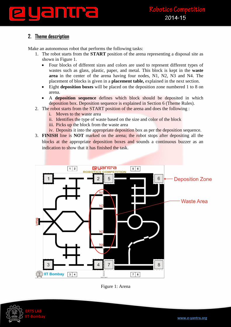
1. The robot starts from the START position of the arena representing a disposal site as
shown in Figure 1.
Four blocks of different sizes and colors are used to represent different types of
wastes such as glass, plastic, paper, and metal. This block is kept in the waste
area in the center of the arena having four nodes, N1, N2, N3 and N4. The
placement of blocks is given in a placement table, explained in the next section.
Eight deposition boxes will be placed on the deposition zone numbered 1 to 8 on
arena.
A deposition sequence defines which block should be deposited in which
deposition box. Deposition sequence is explained in Section 6 (Theme Rules).
2. The robot starts from the START position of the arena and does the following :
i. Moves to the waste area
ii. Identifies the type of waste based on the size and color of the block
iii. Picks up the block from the waste area
iv. Deposits it into the appropriate deposition box as per the deposition sequence.
3. FINISH line is NOT marked on the arena; the robot stops after depositing all the
blocks at the appropriate deposition boxes and sounds a continuous buzzer as an
indication to show that it has finished the task.
Figure 1: Arena
www.e-yantra.org
EE ERTS LAB IIT-Bombay
3. Arena
The arena for this theme is a simplified abstraction of a waste disposal site. One side of the
arena contains black lines on a white surface with four deposition boxes marked 1 to 4 as
shown in Figure 1. The other side contains white lines on a black surface with four deposition
boxes marked 5 to 8 as shown in Figure 1.
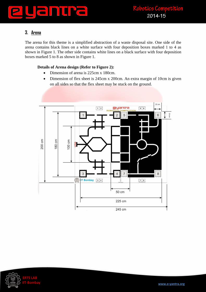
Details of Arena design (Refer to Figure 2):
Dimension of arena is 225cm x 180cm.
Dimension of flex sheet is 245cm x 200cm. An extra margin of 10cm is given
on all sides so that the flex sheet may be stuck on the ground.
Figure 2: Flex design
www.e-yantra.org
EE ERTS LAB IIT-Bombay
The width of black and white lines is 3cm.
The waste area is represented by a rectangular box of dimension 100cm x
50cm in the middle of the arena as shown in Figure 2. The rectangular box has
lines of thickness 3cm.
Four square nodes N1, N2, N3 and N4 of dimension 5cm x 5cm are provided
in the middle of the rectangular box.
The deposition zones are represented by squares of dimension 20cm x 20cm
along the sides of the arena as shown in Figure 2.
Teams are not allowed to make any changes to the arena design. Any team
making any unauthorized modifications will be disqualified from the
competition.
3. 2. Preparing and placing the blocks:
Materials required for preparing the blocks:
Thermocol sheet for making blocks.
Black color chart paper.
Preparing blocks:
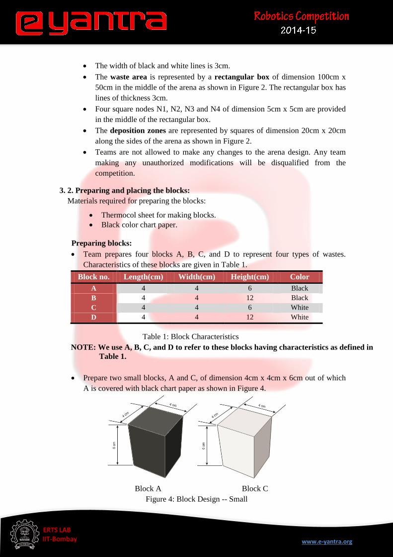
Team prepares four blocks A, B, C, and D to represent four types of wastes.
Characteristics of these blocks are given in Table 1.
Block no. Length(cm) Width(cm) Height(cm) Color
A 4 4 6 Black
B 4 4 12 Black
C 4 4 6 White
D 4 4 12 White
Table 1: Block Characteristics
NOTE: We use A, B, C, and D to refer to these blocks having characteristics as defined in
Table 1.
Prepare two small blocks, A and C, of dimension 4cm x 4cm x 6cm out of which
A is covered with black chart paper as shown in Figure 4.
Block A Block C
Figure 4: Block Design -- Small
www.e-yantra.org
EE ERTS LAB IIT-Bombay
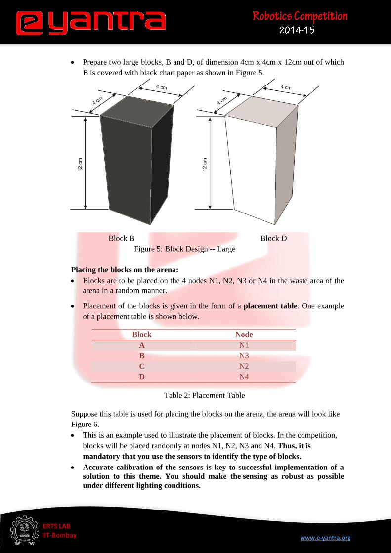
Prepare two large blocks, B and D, of dimension 4cm x 4cm x 12cm out of which
B is covered with black chart paper as shown in Figure 5.
Block B Block D
Figure 5: Block Design -- Large
Placing the blocks on the arena:
Blocks are to be placed on the 4 nodes N1, N2, N3 or N4 in the waste area of the
arena in a random manner.
Placement of the blocks is given in the form of a placement table. One example
of a placement table is shown below.
Block Node
A N1
B N3
C N2
D N4
Table 2: Placement Table
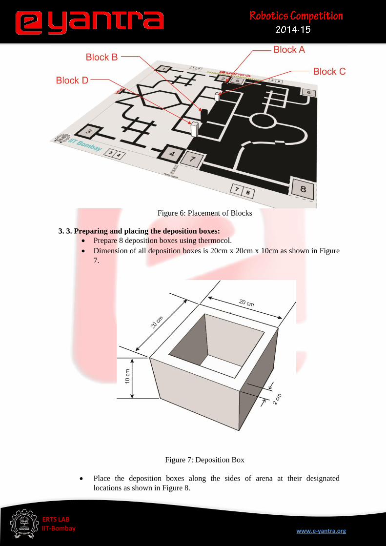
Suppose this table is used for placing the blocks on the arena, the arena will look like
Figure 6.
This is an example used to illustrate the placement of blocks. In the competition,
blocks will be placed randomly at nodes N1, N2, N3 and N4. Thus, it is
mandatory that you use the sensors to identify the type of blocks.
Accurate calibration of the sensors is key to successful implementation of a
solution to this theme. You should make the sensing as robust as possible
under different lighting conditions.
www.e-yantra.org
EE ERTS LAB IIT-Bombay
Figure 6: Placement of Blocks
3. 3. Preparing and placing the deposition boxes:
Prepare 8 deposition boxes using thermocol.
Dimension of all deposition boxes is 20cm x 20cm x 10cm as shown in Figure
7.
Figure 7: Deposition Box
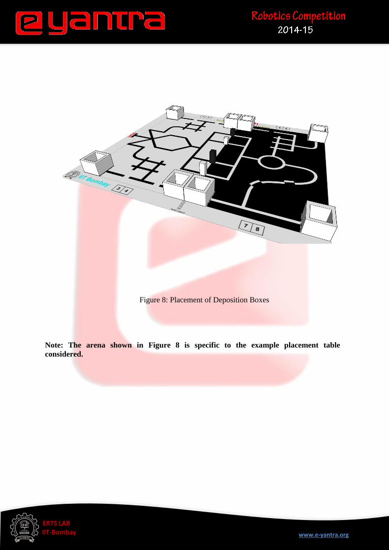
Place the deposition boxes along the sides of arena at their designated
locations as shown in Figure 8.
www.e-yantra.org
EE ERTS LAB IIT-Bombay
Figure 8: Placement of Deposition Boxes
Note: The arena shown in Figure 8 is specific to the example placement table
considered.
www.e-yantra.org
EE ERTS LAB IIT-Bombay
4. Theme Rules
The maximum time allotted to complete the task is 10 minutes. A maximum of two runs
will be given to a team (the better score from the two runs will be considered as the
team’s score). A maximum of two repositions (explained below) will be allowed in each
run.
The team should switch ON the robot when told to do so by reviewer. This is the start
of a run. The timer will start at the same time.
A deposition sequence that defines which block should be deposited in which
deposition box will be given before start of a run. The format for the deposition
sequence is as follows:
START (S) – (deposition box numbers in which the blocks are to be deposited) –FINISH (F)
One example of a deposition sequence is:
S - (2, 1, 7, 8) –F
This deposition sequence requires the team to do the following:
Deposit Block A in deposition box 2.
Deposit Block B in deposition box 1.
Deposit Block C in deposition box 7.
Deposit Block D in deposition box 8.
Note that blocks A, B, C, and D can be picked up and deposited in any
order. But they have to be placed at the appropriate deposition box as given
in the deposition sequence.
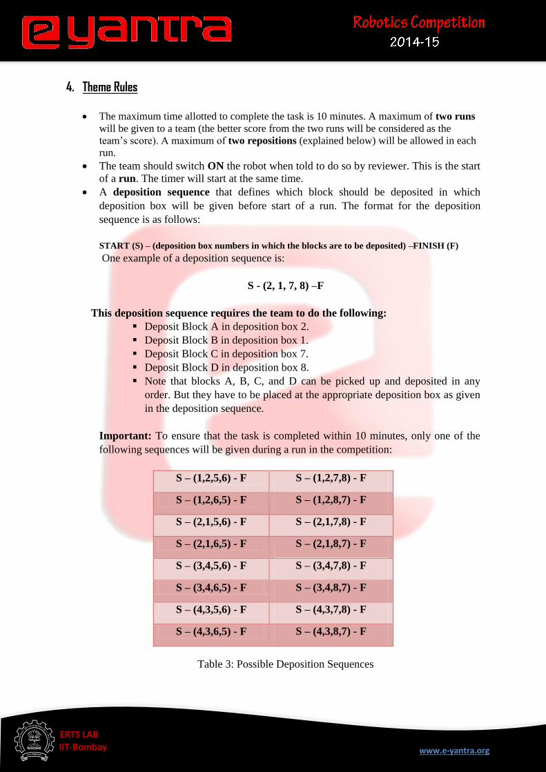
Important: To ensure that the task is completed within 10 minutes, only one of the
following sequences will be given during a run in the competition:
S – (1,2,5,6) - F S – (1,2,7,8) - F
S – (1,2,6,5) - F S – (1,2,8,7) - F
S – (2,1,5,6) - F S – (2,1,7,8) - F
S – (2,1,6,5) - F S – (2,1,8,7) - F
S – (3,4,5,6) - F S – (3,4,7,8) - F
S – (3,4,6,5) - F S – (3,4,8,7) - F
S – (4,3,5,6) - F S – (4,3,7,8) - F
S – (4,3,6,5) - F S – (4,3,8,7) - F
Table 3: Possible Deposition Sequences
www.e-yantra.org
EE ERTS LAB IIT-Bombay
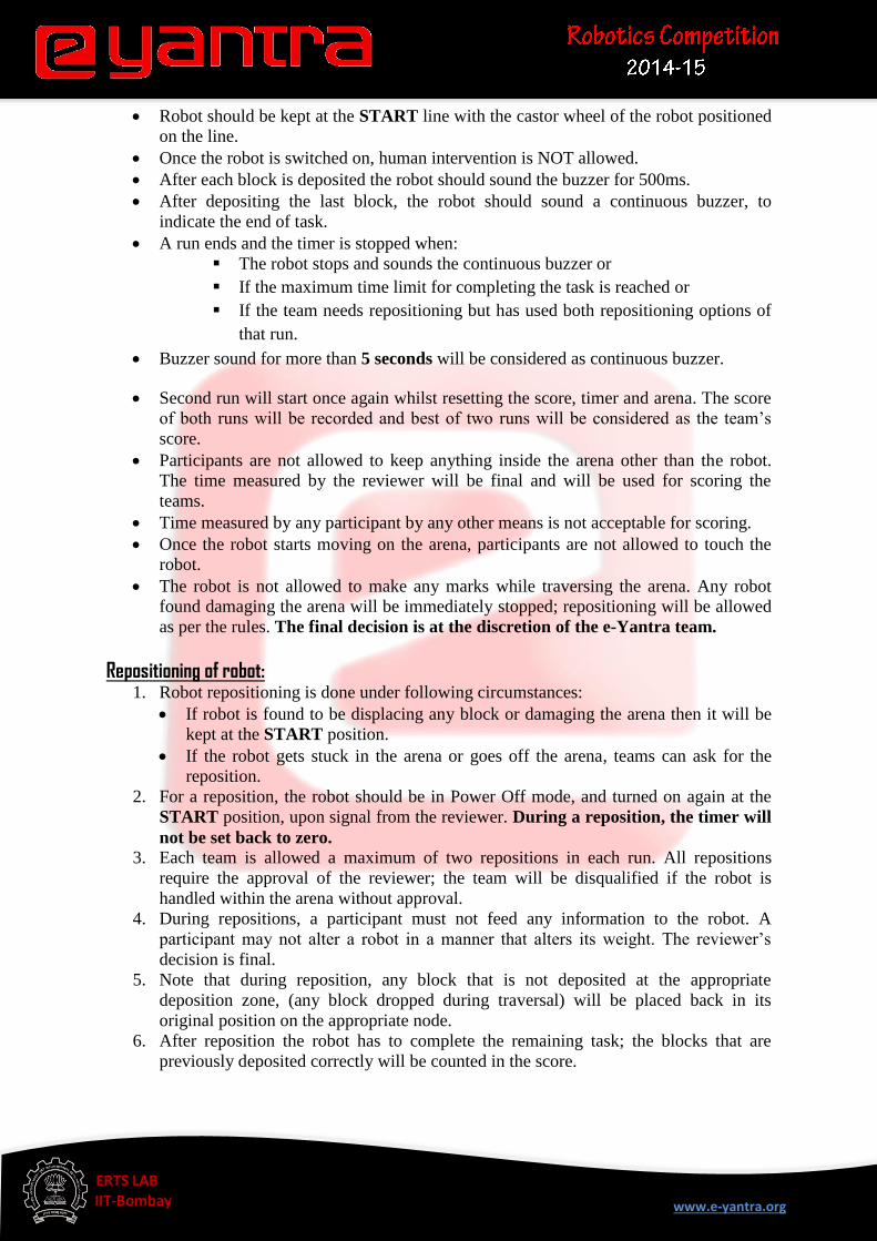
Robot should be kept at the START line with the castor wheel of the robot positioned
on the line.
Once the robot is switched on, human intervention is NOT allowed.
After each block is deposited the robot should sound the buzzer for 500ms.
After depositing the last block, the robot should sound a continuous buzzer, to
indicate the end of task.
A run ends and the timer is stopped when:
The robot stops and sounds the continuous buzzer or
If the maximum time limit for completing the task is reached or
If the team needs repositioning but has used both repositioning options of
that run.
Buzzer sound for more than 5 seconds will be considered as continuous buzzer.
Second run will start once again whilst resetting the score, timer and arena. The score
of both runs will be recorded and best of two runs will be considered as the team’s
score.
Participants are not allowed to keep anything inside the arena other than the robot.
The time measured by the reviewer will be final and will be used for scoring the
teams.
Time measured by any participant by any other means is not acceptable for scoring.
Once the robot starts moving on the arena, participants are not allowed to touch the
robot.
The robot is not allowed to make any marks while traversing the arena. Any robot
found damaging the arena will be immediately stopped; repositioning will be allowed
as per the rules. The final decision is at the discretion of the e-Yantra team.
Repositioning of robot: 1. Robot repositioning is done under following circumstances:
If robot is found to be displacing any block or damaging the arena then it will be
kept at the START position.
If the robot gets stuck in the arena or goes off the arena, teams can ask for the
reposition.
2. For a reposition, the robot should be in Power Off mode, and turned on again at the
START position, upon signal from the reviewer. During a reposition, the timer will
not be set back to zero.
3. Each team is allowed a maximum of two repositions in each run. All repositions
require the approval of the reviewer; the team will be disqualified if the robot is
handled within the arena without approval.
4. During repositions, a participant must not feed any information to the robot. A
participant may not alter a robot in a manner that alters its weight. The reviewer’s
decision is final.
5. Note that during reposition, any block that is not deposited at the appropriate
deposition zone, (any block dropped during traversal) will be placed back in its
original position on the appropriate node.
6. After reposition the robot has to complete the remaining task; the blocks that are
previously deposited correctly will be counted in the score.
www.e-yantra.org
EE ERTS LAB IIT-Bombay
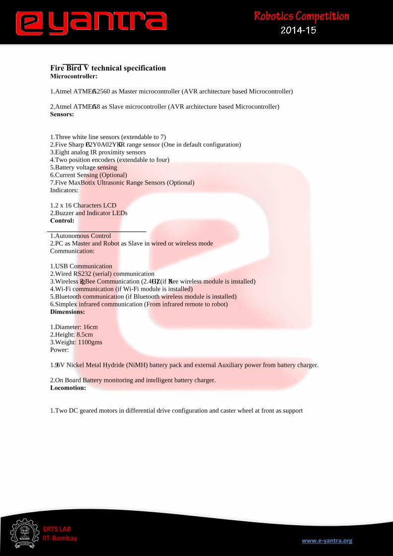
Fire Bird V technical specificationMicrocontroller:
1.Atmel ATMEGA2560 as Master microcontroller (AVR architecture based Microcontroller)
2.Atmel ATMEGA8 as Slave microcontroller (AVR architecture based Microcontroller)
Sensors:
1.Three white line sensors (extendable to 7)
2.Five Sharp GP2Y0A02YK IR range sensor (One in default configuration)
3.Eight analog IR proximity sensors
4.Two position encoders (extendable to four)
5.Battery voltage sensing
6.Current Sensing (Optional)
7.Five MaxBotix Ultrasonic Range Sensors (Optional)
Indicators:
1.2 x 16 Characters LCD
2.Buzzer and Indicator LEDs
Control:
1.Autonomous Control
2.PC as Master and Robot as Slave in wired or wireless mode
Communication:
1.USB Communication
2.Wired RS232 (serial) communication
3.Wireless ZigBee Communication (2.4GHZ) (if XBee wireless module is installed)
4.Wi-Fi communication (if Wi-Fi module is installed)
5.Bluetooth communication (if Bluetooth wireless module is installed)
6.Simplex infrared communication (From infrared remote to robot)
Dimensions:
1.Diameter: 16cm
2.Height: 8.5cm
3.Weight: 1100gms
Power:
1.9.6V Nickel Metal Hydride (NiMH) battery pack and external Auxiliary power from battery charger.
2.On Board Battery monitoring and intelligent battery charger.
Locomotion:
1.Two DC geared motors in differential drive configuration and caster wheel at front as support
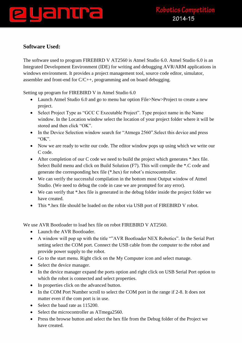
Software Used: The software used to program FIREBIRD V AT2560 is Atmel Studio 6.0. Atmel Studio 6.0 is an
Integrated Development Environment (IDE) for writing and debugging AVR/ARM applications in
windows environment. It provides a project management tool, source code editor, simulator,
assembler and front-end for C/C++, programming and on board debugging.
Setting up program for FIREBIRD V in Atmel Studio 6.0
Launch Atmel Studio 6.0 and go to menu bar option File>New>Project to create a new
project.
Select Project Type as “GCC C Executable Project”. Type project name in the Name
window. In the Location window select the location of your project folder where it will be
stored and then click “OK”.
In the Device Selection window search for “Atmega 2560”.Select this device and press
“OK”.
Now we are ready to write our code. The editor window pops up using which we write our
C code.
After completion of our C code we need to build the project which generates *.hex file.
Select Build menu and click on Build Solution (F7). This will compile the *.C code and
generate the corresponding hex file (*.hex) for robot’s microcontroller.
We can verify the successful compilation in the bottom most Output window of Atmel
Studio. (We need to debug the code in case we are prompted for any error).
We can verify that *.hex file is generated in the debug folder inside the project folder we
have created.
This *.hex file should be loaded on the robot via USB port of FIREBIRD V robot.
We use AVR Bootloader to load hex file on robot FIREBIRD V AT2560.
Launch the AVR Bootloader.
A window will pop up with the title “”AVR Bootloader NEX Robotics”. In the Serial Port
setting select the COM port. Connect the USB cable from the computer to the robot and
provide power supply to the robot.
Go to the start menu. Right click on the My Computer icon and select manage.
Select the device manager.
In the device manager expand the ports option and right click on USB Serial Port option to
which the robot is connected and select properties.
In properties click on the advanced button.
In the COM Port Number scroll to select the COM port in the range if 2-8. It does not
matter even if the com port is in use.
Select the baud rate as 115200.
Select the microcontroller as ATmega2560.
Press the browse button and select the hex file from the Debug folder of the Project we
have created.

Put the robot in the boot mode(By first pressing and holding boot switch then press reset
button and finally release reset button followed by boot switch ) and click on the
“Program” button. In case of any error, unplug the USB cable and put it back again. Put
robot in boot mode and then click on “Program” button again.
We will get a window when burnt successful.