Embed Size (px)
Citation preview
Chapter 30
Architectural DraftingUsing AutoCAD
Copyright by Goodheart-Willcox Co., Inc. Chapter30Exercises �
E x E r C I s E s
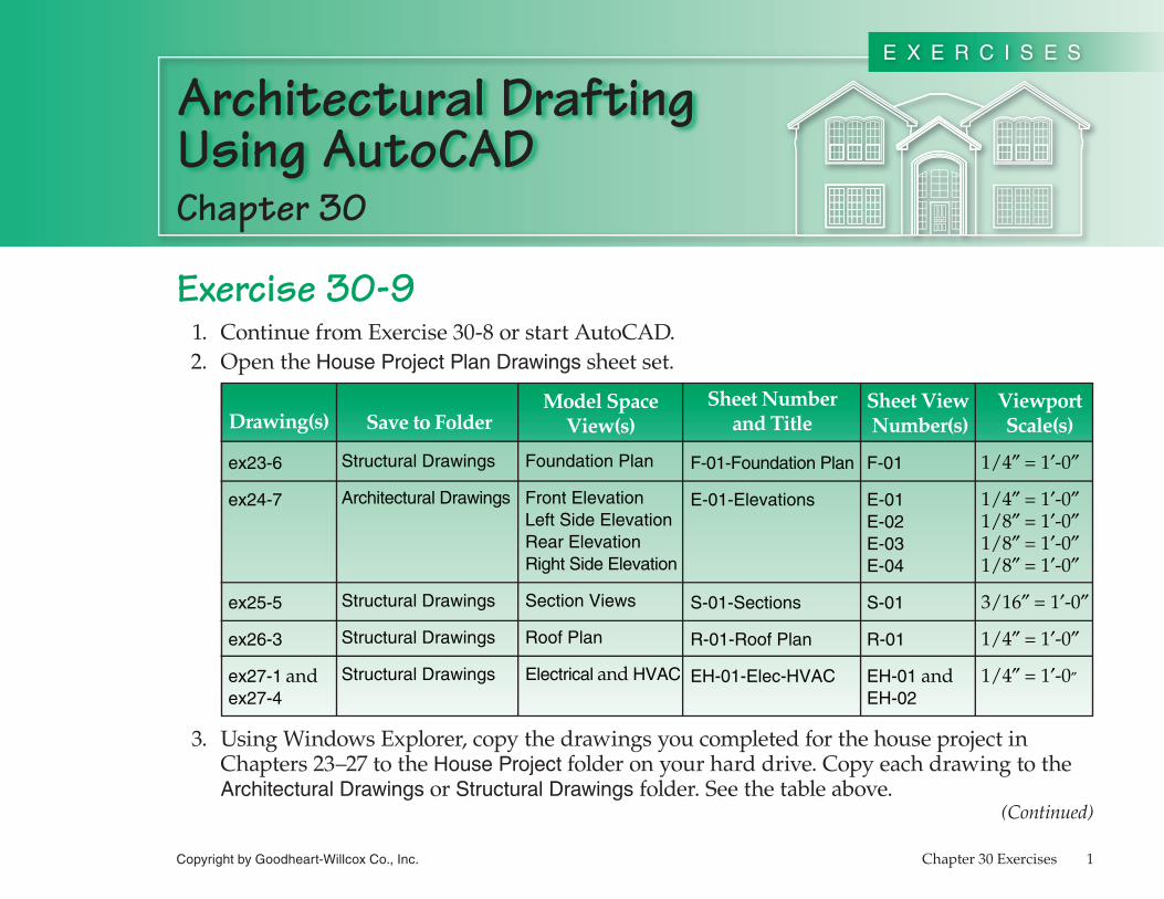
Exercise 30-9 �. ContinuefromExercise30-8orstartAutoCAD. 2. OpentheHouse Project Plan Drawingssheetset.
Drawing(s) Save to FolderModel Space
View(s)Sheet Number
and TitleSheet View Number(s)
ViewportScale(s)
ex23-6
ex24-7
ex25-5
ex26-3
ex27-1 andex27-4
Structural Drawings
Architectural Drawings
Structural Drawings
Structural Drawings
Structural Drawings
Foundation Plan
Front ElevationLeft Side ElevationRear ElevationRight Side Elevation
Section Views
Roof Plan
Electrical and HVAC
F-01-Foundation Plan
E-01-Elevations
S-01-Sections
R-01-Roof Plan
EH-01-Elec-HVAC
F-01
E-01E-02E-03E-04
S-01
R-01
EH-01 andEH-02
1/4″ = 1′-0″
1/4″ = 1′-0″1/8″ = 1′-0″1/8″ = 1′-0″1/8″ = 1′-0″
3/16″ = 1′-0″
1/4″ = 1′-0″
1/4″ = 1′-0″
3. UsingWindowsExplorer,copythedrawingsyoucompletedforthehouseprojectinChapters23–27totheHouse Projectfolderonyourharddrive.CopyeachdrawingtotheArchitectural Drawingsorstructural Drawings folder.Seethetableabove.
(Continued)
Chapter 30
Architectural DraftingUsing AutoCAD
Copyright by Goodheart-Willcox Co., Inc. Chapter30Exercises 2
E x E r C I s E s
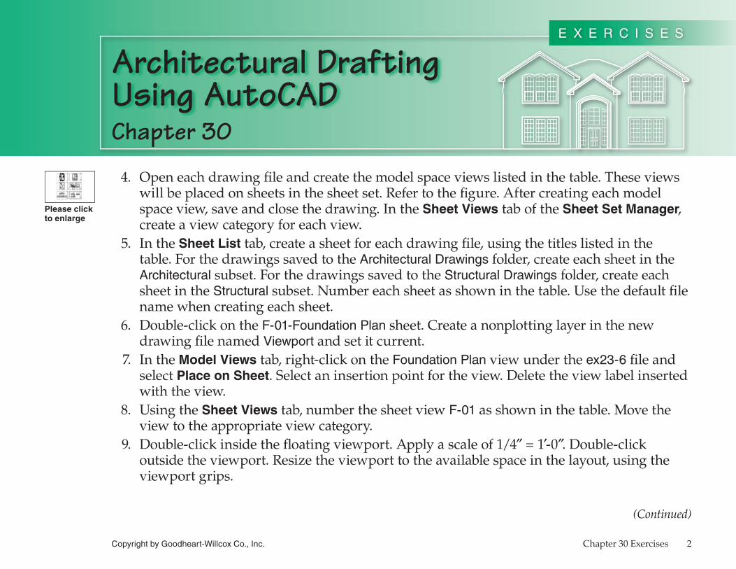
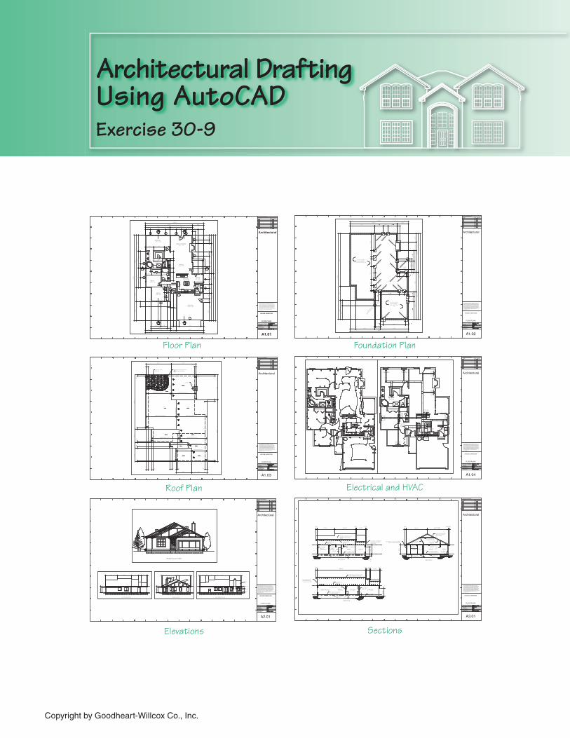
4. Openeachdrawingfileandcreatethemodelspaceviewslistedinthetable.Theseviewswillbeplacedonsheetsinthesheetset.Refertothefigure.Aftercreatingeachmodelspaceview,saveandclosethedrawing.IntheSheet ViewstaboftheSheet Set Manager,createaviewcategoryforeachview.
5. IntheSheet Listtab,createasheetforeachdrawingfile,usingthetitleslistedinthetable.ForthedrawingssavedtotheArchitectural Drawingsfolder,createeachsheetintheArchitecturalsubset.Forthedrawingssavedtothestructural Drawings folder,createeachsheetinthestructuralsubset.Numbereachsheetasshowninthetable.Usethedefaultfilenamewhencreatingeachsheet.
6. Double-clickontheF-01-Foundation Plansheet.CreateanonplottinglayerinthenewdrawingfilenamedViewportandsetitcurrent.
7. IntheModel Viewstab,right-clickontheFoundation Planviewundertheex23-6fileandselectPlace on Sheet.Selectaninsertionpointfortheview.Deletetheviewlabelinsertedwiththeview.
8. UsingtheSheet Viewstab,numberthesheetviewF-01asshowninthetable.Movetheviewtotheappropriateviewcategory.
9. Double-clickinsidethefloatingviewport.Applyascaleof�/4″=�′-0″.Double-clickoutsidetheviewport.Resizetheviewporttotheavailablespaceinthelayout,usingtheviewportgrips.
(Continued)
Please click to enlarge
FOYER
3'-6" 11'-0" 3'-2" 4'-6" 3'-6" 4'-10" 4'-0"
17'-8" 16'-4"
34'-0" 8'-0"
42'-0"
9'-2"
3'-2"
6'-11"
7'-3"
11'-6"
12'-4"
14'-2"
38'-0"
10'-0"
14'-0"
62'-0"
7'-0" 4'-4" 2'-0" 2'-0" 2'-0" 16'-0" 2'-0"
11'-4" 2'-8"
4'-0" 14'-0" 4'-0" 20'-0"
42'-0"
3'-6"
2'-9"
6'-0"
2'-9"
8'-0"
5'-0"
4'-0"
3'-2"
4'-0"
13'-0"
3'-0"
3'-6"
3'-4"
6'-3"
15'-9"
34'-0"
6'-8"
20'-0"
7'-4"
28'-0"
62'-0"
4'-0"
2'-0"
5'-8" 7'-8" 4'-2"
4'-4" 7'-0"
4'-0" 2'-4" 4'-6"
2'-4"
5'-4"
1'-8"
5'-4"
3'-0"
6'-4"
6'-5" 3'-6"
4'-0"
6'-4"
6'-10"
3'-6"
UTILDW SINK OVEN
RANGEREFER
DESK PANTRY
WASHER
DRYER
4'-0"
9'-9"
AA3.01 BA3.01
AA3.01 BA3.01
CA3.01 CA3.01
01
0203
04
05
06
07
08
09
10
11
12
13
14
15
16
17
XMASTER17/0 10/10
XGREAT ROOM15/8 17/6
XDINING15/8 10/2
XMBATH11/4 12/0
XBED210/8 13/6
XBATH6/0 9/0
XBED310/8 9/8
XKITCHEN12/0 13/0 XNOOK8/0 6/8
XGARAGE19/0 19/6
01
02
03
04 05 06 07
08
09
10
11
Chapter 30
Architectural DraftingUsing AutoCAD
Copyright by Goodheart-Willcox Co., Inc. Chapter30Exercises 3
E x E r C I s E s
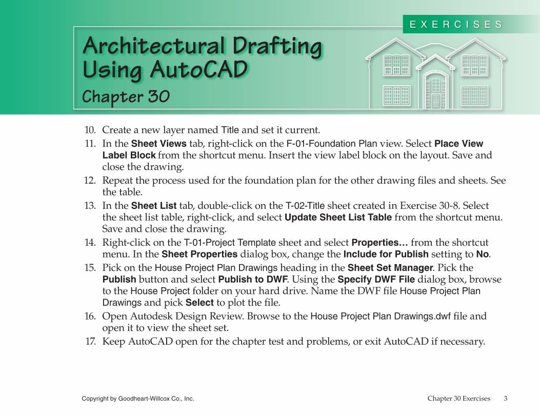
�0. CreateanewlayernamedTitleandsetitcurrent.��. IntheSheet Viewstab,right-clickontheF-01-Foundation Planview.SelectPlace View
Label Block fromtheshortcutmenu.Inserttheviewlabelblockonthelayout.Saveandclosethedrawing.
�2. Repeattheprocessusedforthefoundationplanfortheotherdrawingfilesandsheets.Seethetable.
�3. IntheSheet Listtab,double-clickontheT-02-TitlesheetcreatedinExercise30-8.Selectthesheetlisttable,right-click,andselectUpdate Sheet List Tablefromtheshortcutmenu.Saveandclosethedrawing.
�4. Right-clickontheT-01-Project TemplatesheetandselectProperties…fromtheshortcutmenu.IntheSheet Propertiesdialogbox,changetheInclude for PublishsettingtoNo.
�5. PickontheHouse Project Plan DrawingsheadingintheSheet Set Manager.PickthePublishbuttonandselectPublish to DWF.UsingtheSpecify DWF Filedialogbox,browsetotheHouse Projectfolderonyourharddrive.NametheDWFfileHouse Project Plan DrawingsandpickSelecttoplotthefile.
�6. OpenAutodeskDesignReview.BrowsetotheHouse Project Plan Drawings.dwffileandopenittoviewthesheetset.
�7. KeepAutoCADopenforthechaptertestandproblems,orexitAutoCADifnecessary.
Architectural DraftingUsing AutoCAD
Copyright by Goodheart-Willcox Co., Inc.
Exercise 30-9
FOYER
3'-6" 11'-0" 3'-2" 4'-6" 3'-6" 4'-10" 4'-0"
17'-8" 16'-4"
34'-0" 8'-0"
42'-0"
9'-2
"3
'-2"
6'-1
1"
7'-3
"
11
'-6"
12
'-4"
14
'-2"
38
'-0"
10
'-0"
14
'-0"
62
'-0"
7'-0" 4'-4" 2'-0" 2'-0" 2'-0" 16'-0" 2'-0"
11'-4" 2'-8"
4'-0" 14'-0" 4'-0" 20'-0"
42'-0"
3'-6
"2
'-9"
6'-0
"
2'-9
"8
'-0"
5'-0
"4
'-0"
3'-2
"4
'-0"
13
'-0"
3'-0
"3
'-6"
3'-4
"
6'-3
"1
5'-9
"
34
'-0"
6'-8
"2
0'-0
"7
'-4"
28
'-0"
62
'-0"
4'-0"
2'-0"
5'-8" 7'-8" 4'-2"
4'-4" 7'-0"
4'-0" 2'-4" 4'-6"
2'-4
"
5'-4
"1
'-8"
5'-4
"3
'-0"
6'-4
"
6'-5" 3'-6"
4'-0
"6
'-4"
6'-10"
3'-6"
UTILDW SINK OVEN
RANGE
REF
ER
DESK PANTRY
WAS
HER
DRYE
R
4'-0
"
9'-9
"
AA3.01
BA3.01
AA3.01
BA3.01
CA3.01
CA3.01
01
0203
04
05
06
07
08
09
10
11
12
13
14
15
16
17
XMASTER17/0 10/10
XGREAT ROOM
15/8 17/6
XDINING
15/8 10/2
XMBATH
11/4 12/0
XBED2
10/8 13/6
XBATH
6/0 9/0
XBED3
10/8 9/8
XKITCHEN12/0 13/0
XNOOK8/0 6/8
XGARAGE19/0 19/6
01
02
03
04 05 06 07
08
09
10
11