Embed Size (px)
Citation preview
E-VECTOORC, A Model of CooperationPhil Barber
Automotive Electronic Systems Innovation Network (AESIN)
UK Automotive Electronics Conference
October 2014
Contents
• Who
• What
• When
• (Details)
• Dissemination
Electric Vehicle Control of Individual Wheel Torque for On- and Off-Road Conditions
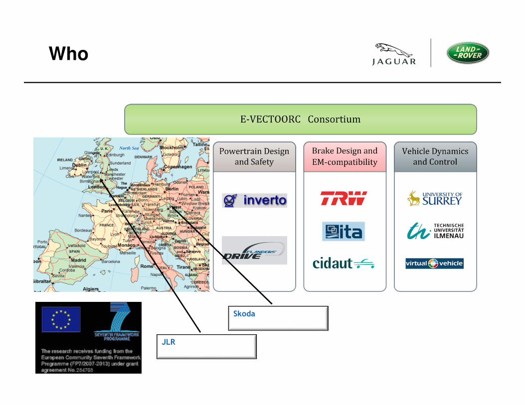
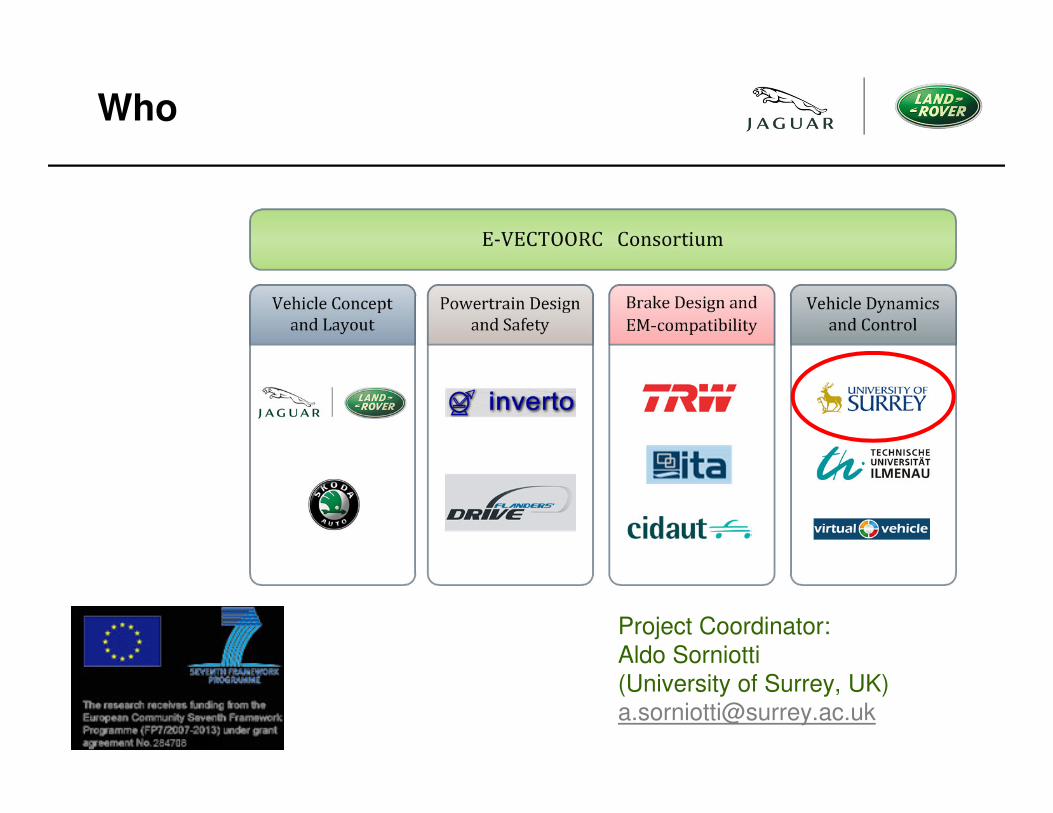
Who
Skoda
JLR
Who
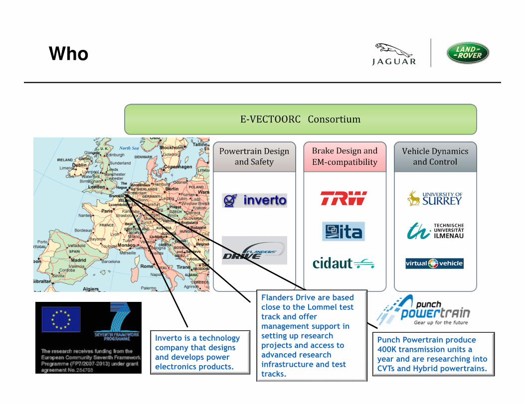
Inverto is a technology company that designs and develops power electronics products.
Punch Powertrain produce 400K transmission units a year and are researching into CVTs and Hybrid powertrains.
Flanders Drive are based close to the Lommel test track and offer management support in setting up research projects and access to advanced research infrastructure and test tracks.
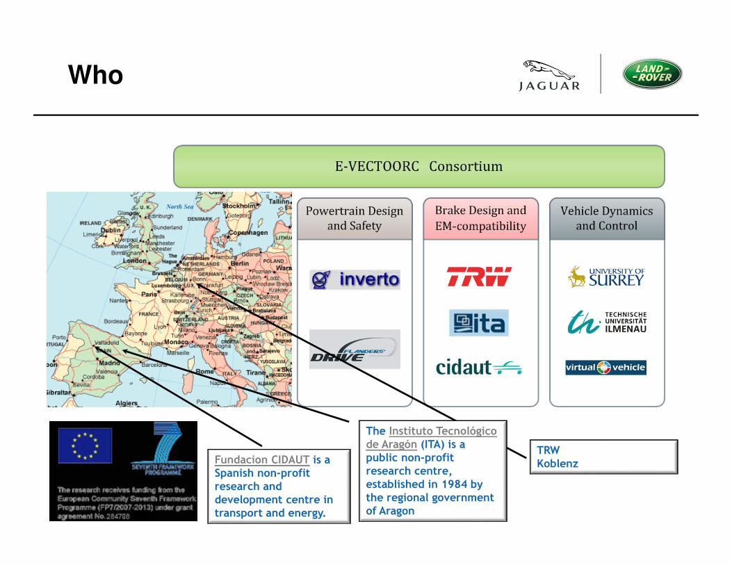
Who
The Instituto Tecnológicode Aragón (ITA) is a public non-profit research centre, established in 1984 by the regional government of Aragon
Fundacion CIDAUT is a Spanish non-profit research and development centre in transport and energy.
TRWKoblenz
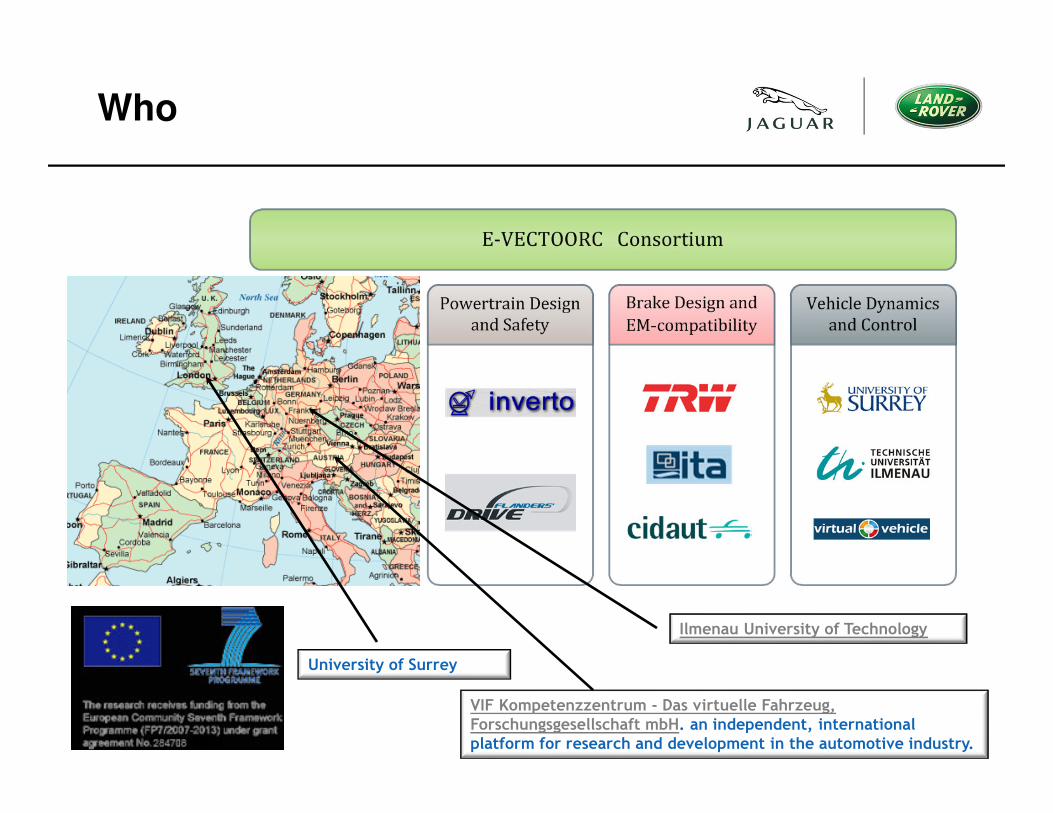
Who
University of Surrey
Ilmenau University of Technology
VIF Kompetenzzentrum - Das virtuelle Fahrzeug, Forschungsgesellschaft mbH. an independent, international platform for research and development in the automotive industry.
What
• (for video see www.e-vectoorc.eu)
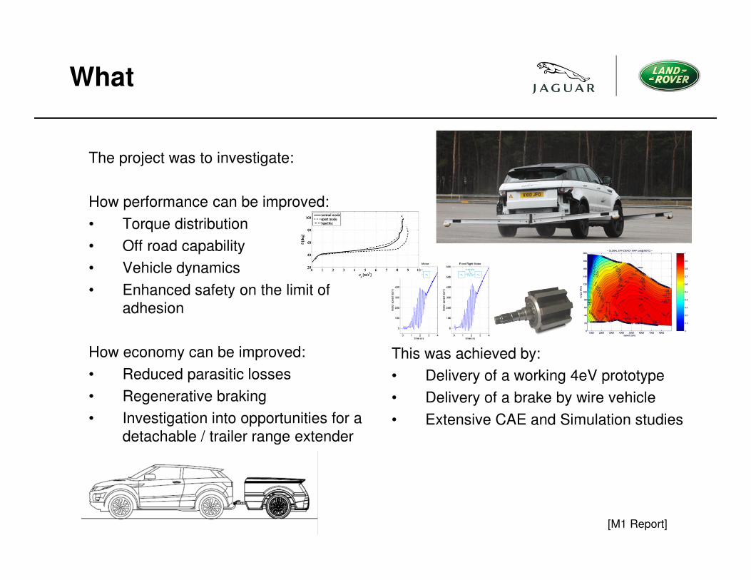
What
This was achieved by:
• Delivery of a working 4eV prototype
• Delivery of a brake by wire vehicle
• Extensive CAE and Simulation studies
[M1 Report]
The project was to investigate:
How performance can be improved:
• Torque distribution
• Off road capability
• Vehicle dynamics
• Enhanced safety on the limit of
adhesion
How economy can be improved:
• Reduced parasitic losses
• Regenerative braking
• Investigation into opportunities for a
detachable / trailer range extender
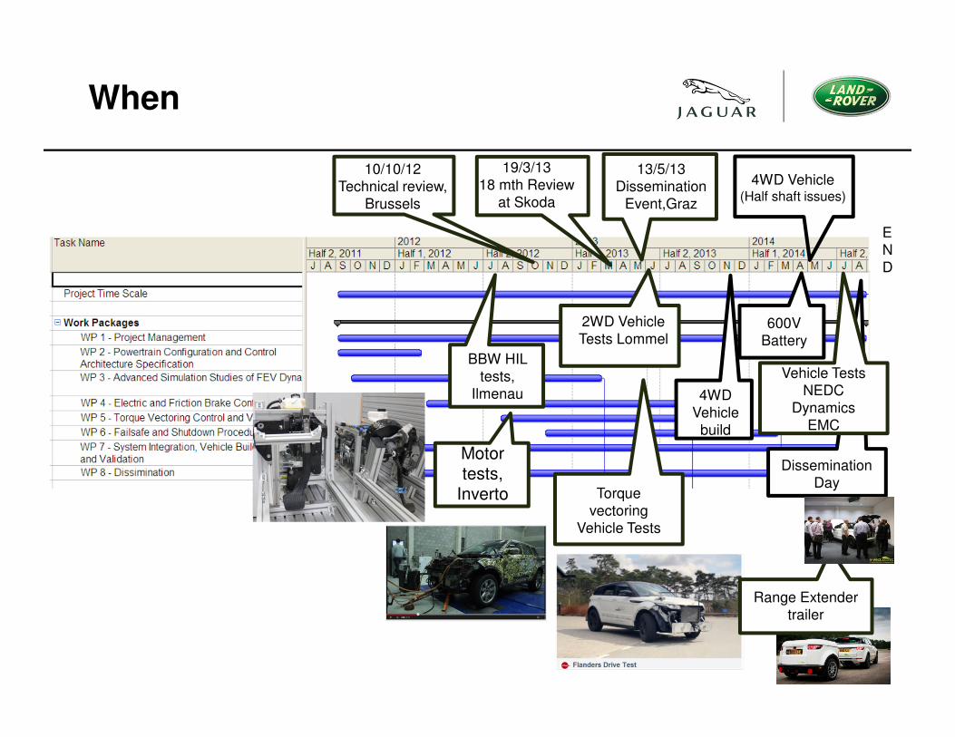
When
19/3/13
18 mth Review
at Skoda
2WD Vehicle
Tests Lommel
13/5/13
Dissemination
Event,Graz
BBW HIL
tests,
Ilmenau
10/10/12
Technical review,
Brussels
Motor tests,
Inverto Torque
vectoring
Vehicle Tests
600V
Battery
4WD Vehicle(Half shaft issues)
4WD
Vehicle
build
Range Extender
trailer
Dissemination
Day
Vehicle Tests
NEDC
Dynamics
EMC
E
N
D
Details
• 4WD, 4 x Electric SR, inboard motor Evoque
• 600V, 9KWh battery pack
• TRW Brake by wire system + HIL rig at Ilmenau University
• Brake Blending and eABS
• Torque apportionment algorithms for understeer gradient
compensation.
• Active (torsional) vibration control (electric anti shunt)
• Range extender trailer
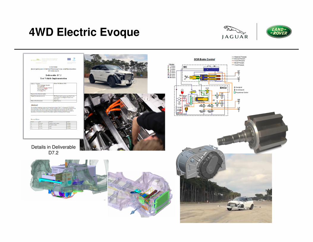
4WD Electric Evoque
Details in Deliverable
D7.2
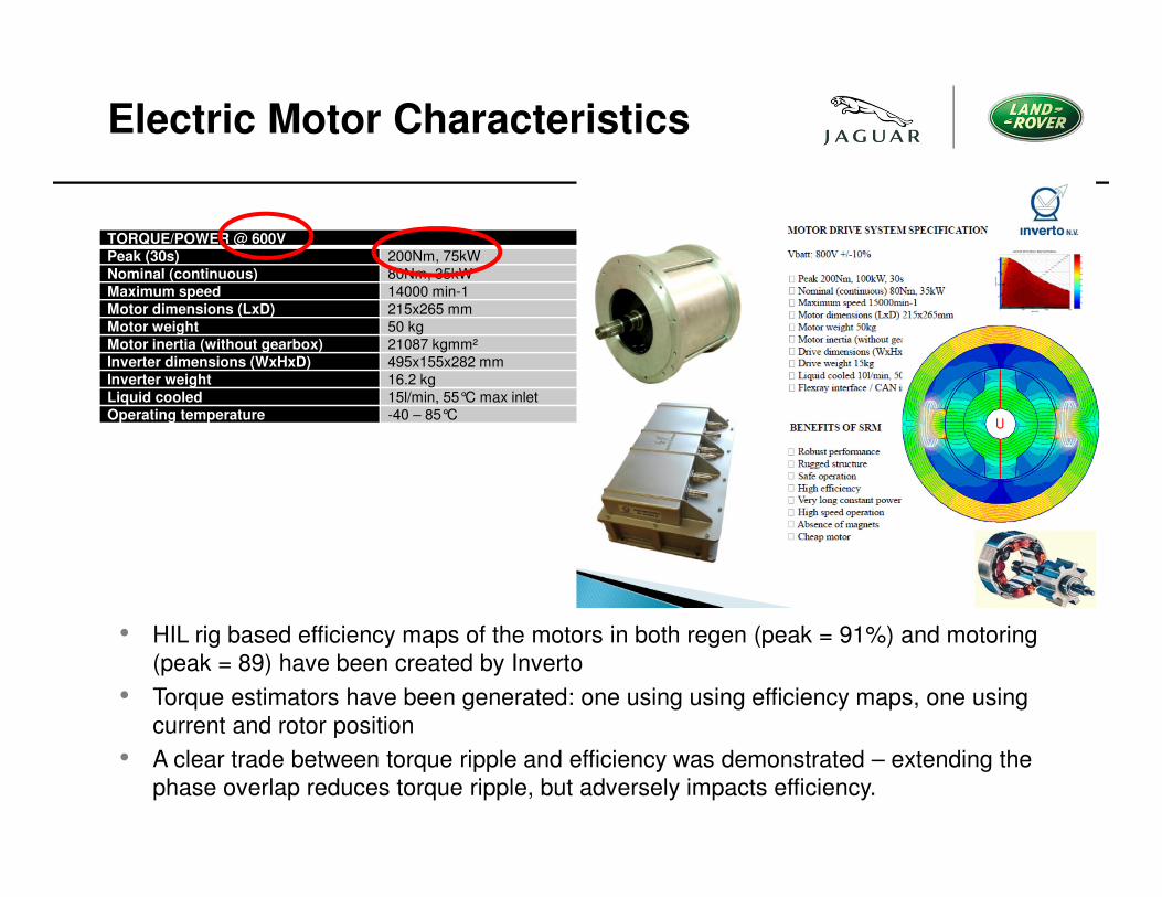
TORQUE/POWER @ 600VPeak (30s) 200Nm, 75kW
Nominal (continuous) 80Nm, 35kW
Maximum speed 14000 min-1
Motor dimensions (LxD) 215x265 mm
Motor weight 50 kg
Motor inertia (without gearbox) 21087 kgmm²
Inverter dimensions (WxHxD) 495x155x282 mm
Inverter weight 16.2 kg
Liquid cooled 15l/min, 55°C max inlet
Operating temperature -40 – 85°C
Electric Motor Characteristics
• HIL rig based efficiency maps of the motors in both regen (peak = 91%) and motoring
(peak = 89) have been created by Inverto
• Torque estimators have been generated: one using using efficiency maps, one using
current and rotor position
• A clear trade between torque ripple and efficiency was demonstrated – extending the
phase overlap reduces torque ripple, but adversely impacts efficiency.
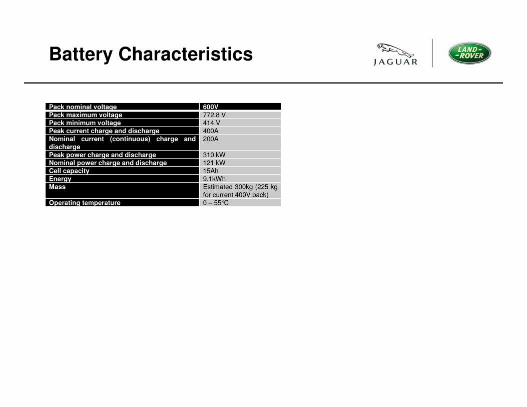
Battery Characteristics
Pack nominal voltage 600VPack maximum voltage 772.8 V
Pack minimum voltage 414 V
Peak current charge and discharge 400A
Nominal current (continuous) charge anddischarge
200A
Peak power charge and discharge 310 kW
Nominal power charge and discharge 121 kW
Cell capacity 15Ah
Energy 9.1kWh
Mass Estimated 300kg (225 kg
for current 400V pack)
Operating temperature 0 – 55°C
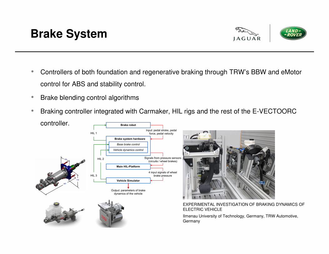
Brake System
• Controllers of both foundation and regenerative braking through TRW’s BBW and eMotor
control for ABS and stability control.
• Brake blending control algorithms
• Braking controller integrated with Carmaker, HIL rigs and the rest of the E-VECTOORC
controller.
EXPERIMENTAL INVESTIGATION OF BRAKING DYNAMICS OF
ELECTRIC VEHICLE
Ilmenau University of Technology, Germany, TRW Automotive,
Germany
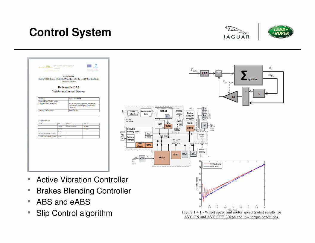
Control System
Figure 1.4.1.- Wheel speed and motor speed (rad/s) results for
AVC ON and AVC OFF. 30kph and low torque conditions.
• Active Vibration Controller
• Brakes Blending Controller
• ABS and eABS
• Slip Control algorithm
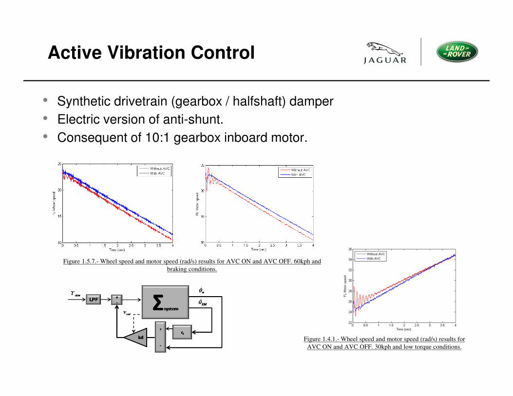
Active Vibration Control
Figure 1.4.1.- Wheel speed and motor speed (rad/s) results for
AVC ON and AVC OFF. 30kph and low torque conditions.
• Synthetic drivetrain (gearbox / halfshaft) damper
• Electric version of anti-shunt.
• Consequent of 10:1 gearbox inboard motor.
Figure 1.5.7.- Wheel speed and motor speed (rad/s) results for AVC ON and AVC OFF. 60kph and
braking conditions.
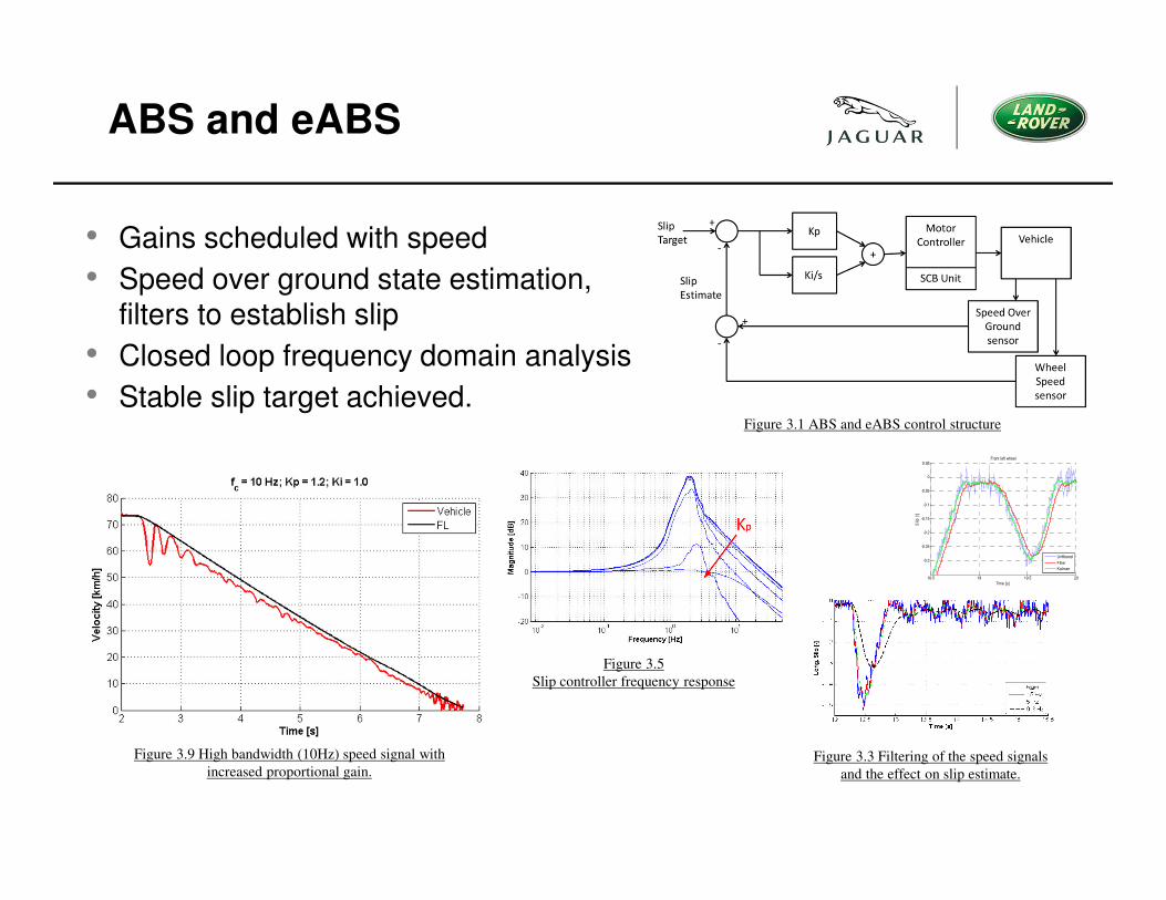
ABS and eABS
Figure 3.1 ABS and eABS control structure
• Gains scheduled with speed
• Speed over ground state estimation, filters to establish slip
• Closed loop frequency domain analysis
• Stable slip target achieved.
Figure 3.5
Slip controller frequency response
Figure 3.3 Filtering of the speed signals
and the effect on slip estimate.
Figure 3.9 High bandwidth (10Hz) speed signal with
increased proportional gain.
18.5 19 19.5 20
-0.3
-0.25
-0.2
-0.15
-0.1
-0.05
0
0.05
Time [s]
Slip
[/]
Front left wheel
Unfiltered
Filter
Kalman
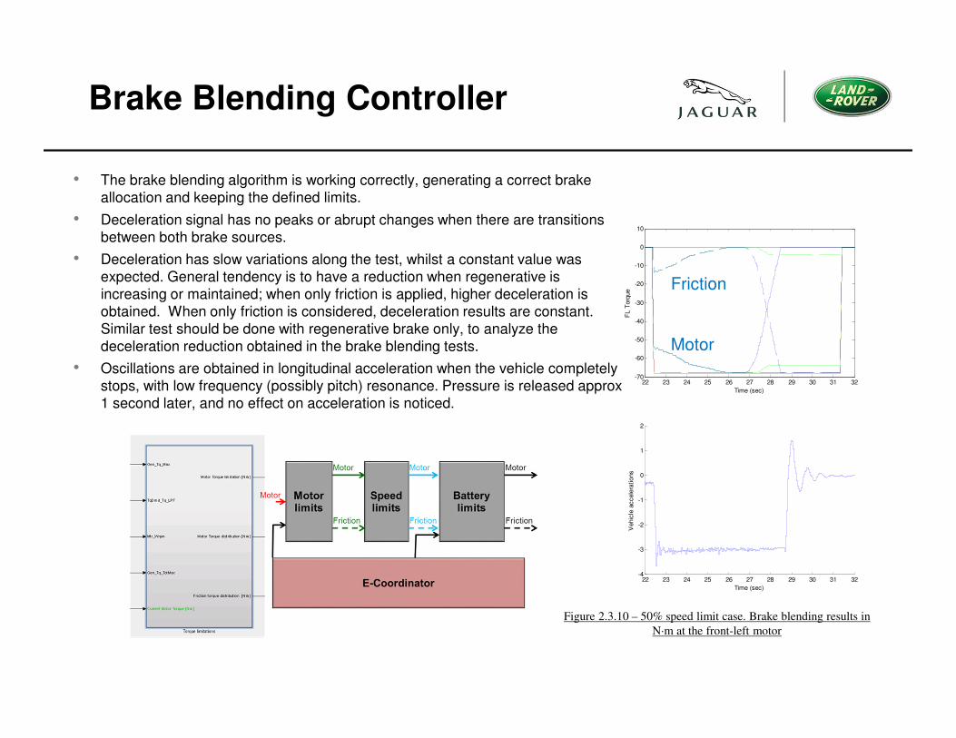
Brake Blending Controller
• The brake blending algorithm is working correctly, generating a correct brake
allocation and keeping the defined limits.
• Deceleration signal has no peaks or abrupt changes when there are transitions
between both brake sources.
• Deceleration has slow variations along the test, whilst a constant value was
expected. General tendency is to have a reduction when regenerative is
increasing or maintained; when only friction is applied, higher deceleration is
obtained. When only friction is considered, deceleration results are constant.
Similar test should be done with regenerative brake only, to analyze the
deceleration reduction obtained in the brake blending tests.
• Oscillations are obtained in longitudinal acceleration when the vehicle completely
stops, with low frequency (possibly pitch) resonance. Pressure is released approx
1 second later, and no effect on acceleration is noticed.
22 23 24 25 26 27 28 29 30 31 32-4
-3
-2
-1
0
1
2
Time (sec)
Vehic
le a
ccele
rations
22 23 24 25 26 27 28 29 30 31 32-70
-60
-50
-40
-30
-20
-10
0
10
Time (sec)
FL T
orq
ue
Figure 2.3.10 – 50% speed limit case. Brake blending results in
N·m at the front-left motor
Motor
Friction
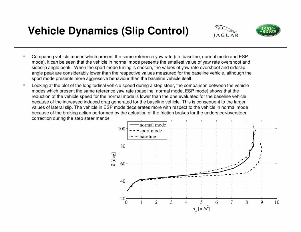
Vehicle Dynamics (Slip Control)
• Comparing vehicle modes which present the same reference yaw rate (i.e. baseline, normal mode and ESP
mode), it can be seen that the vehicle in normal mode presents the smallest value of yaw rate overshoot and
sideslip angle peak. When the sport mode tuning is chosen, the values of yaw rate overshoot and sideslip
angle peak are considerably lower than the respective values measured for the baseline vehicle, although the
sport mode presents more aggressive behaviour than the baseline vehicle itself.
• Looking at the plot of the longitudinal vehicle speed during a step steer, the comparison between the vehicle
modes which present the same reference yaw rate (baseline, normal mode, ESP mode) shows that the
reduction of the vehicle speed for the normal mode is lower than the one evaluated for the baseline vehicle
because of the increased induced drag generated for the baseline vehicle. This is consequent to the larger
values of lateral slip. The vehicle in ESP mode decelerates more with respect to the vehicle in normal mode
because of the braking action performed by the actuation of the friction brakes for the understeer/oversteer
correction during the step steer manoeuvre.
Figure 4.3.3 – Skid pad tests carried out at radius R = 60 m for the 2WD version of the vehicle
demonstrator.
Baseline vehicle (dot-dashed line),
torque-vectoring vehicle in normal mode (solid line)
and torque-vectoring vehicle in sport mode (dashed line
0 1 2 3 4 5 6 7 8 9 1020
40
60
80
100
ay [m/s
2]
δ [
deg
]
normal mode
sport mode
baseline
Trailer Range Extender
Requirements
• 20kW installed, 4-600V delivered
• To support 2hrs continuous usage of vehicle
It was resolved by the consortia that this range extender market is very fast
moving. Direct competition in this market was not of primary interest to the
development of the project aims, however a new concept of a demountable range
extender was to be investigated.
This would both support the track testing and investigate the utility and
acceptability of this concept for inter-city hybrid mobility.
The target mass of the developed trailer was to be close to the 750Kg threshold
for trailers where there is a breakpoint in the driver licencing requirements.
The trailer had to be aesthetically appealing to the market.
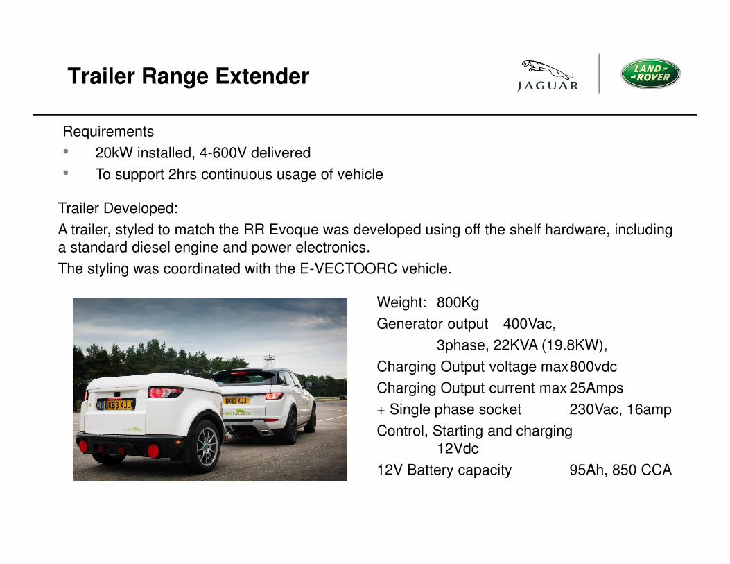
Trailer Range Extender
Weight: 800Kg
Generator output 400Vac,
3phase, 22KVA (19.8KW),
Charging Output voltage max800vdc
Charging Output current max 25Amps
+ Single phase socket 230Vac, 16amp
Control, Starting and charging
12Vdc
12V Battery capacity 95Ah, 850 CCA
Requirements
• 20kW installed, 4-600V delivered
• To support 2hrs continuous usage of vehicle
Trailer Developed:
A trailer, styled to match the RR Evoque was developed using off the shelf hardware, including
a standard diesel engine and power electronics.
The styling was coordinated with the E-VECTOORC vehicle.
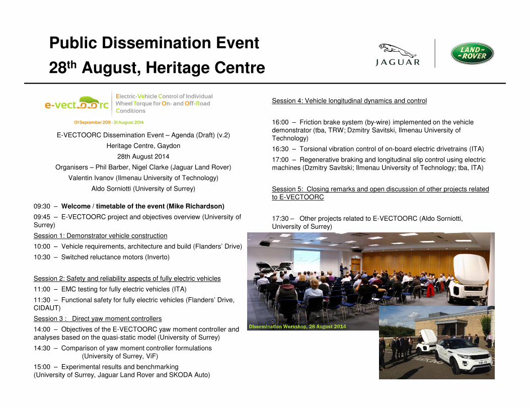
Public Dissemination Event
28th August, Heritage Centre
09:30 – Welcome / timetable of the event (Mike Richardson)
09:45 – E-VECTOORC project and objectives overview (University of
Surrey)
Session 1: Demonstrator vehicle construction
10:00 – Vehicle requirements, architecture and build (Flanders’ Drive)
10:30 – Switched reluctance motors (Inverto)
Session 2: Safety and reliability aspects of fully electric vehicles
11:00 – EMC testing for fully electric vehicles (ITA)
11:30 – Functional safety for fully electric vehicles (Flanders’ Drive,
CIDAUT)
Session 3 : Direct yaw moment controllers
14:00 – Objectives of the E-VECTOORC yaw moment controller and
analyses based on the quasi-static model (University of Surrey)
14:30 – Comparison of yaw moment controller formulations
(University of Surrey, ViF)
15:00 – Experimental results and benchmarking
(University of Surrey, Jaguar Land Rover and SKODA Auto)
Session 4: Vehicle longitudinal dynamics and control
16:00 – Friction brake system (by-wire) implemented on the vehicle
demonstrator (tba, TRW; Dzmitry Savitski, Ilmenau University of
Technology)
16:30 – Torsional vibration control of on-board electric drivetrains (ITA)
17:00 – Regenerative braking and longitudinal slip control using electric
machines (Dzmitry Savitski; Ilmenau University of Technology; tba, ITA)
Session 5: Closing remarks and open discussion of other projects related
to E-VECTOORC
17:30 – Other projects related to E-VECTOORC (Aldo Sorniotti,
University of Surrey)
E-VECTOORC Dissemination Event – Agenda (Draft) (v.2)
Heritage Centre, Gaydon
28th August 2014
Organisers – Phil Barber, Nigel Clarke (Jaguar Land Rover)
Valentin Ivanov (Ilmenau University of Technology)
Aldo Sorniotti (University of Surrey)
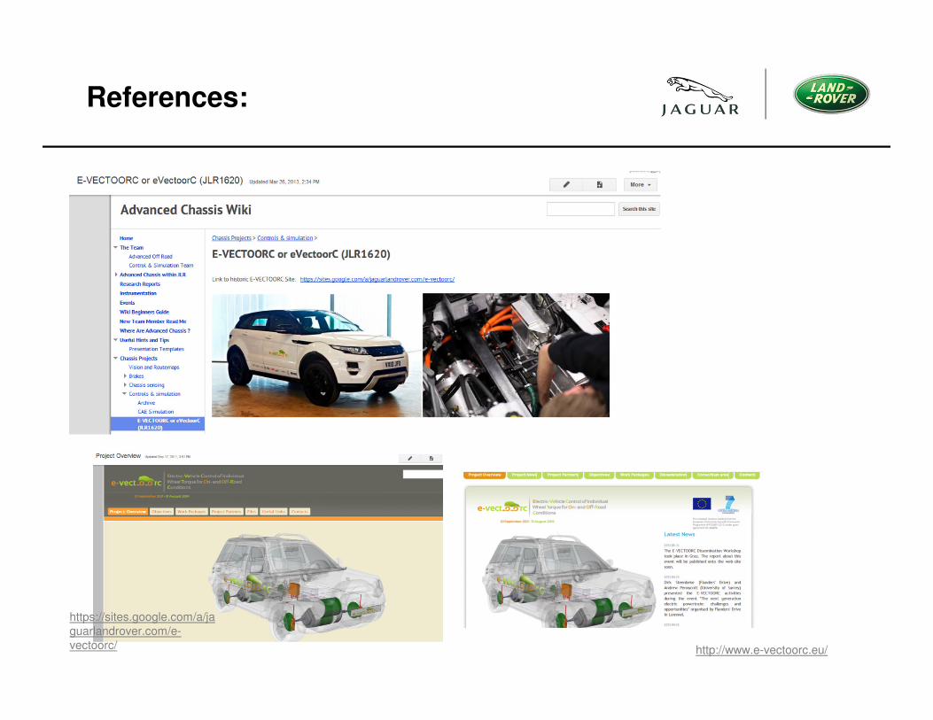
References:
https://sites.google.com/a/ja
guarlandrover.com/e-
vectoorc/ http://www.e-vectoorc.eu/
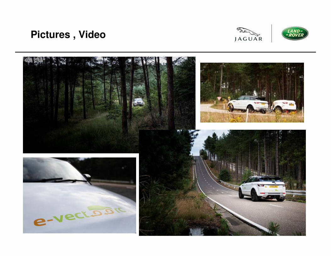
Pictures , Video
Next:
• Feed of results into other research and delivery programs
• Further research inside JLR...
• Further EC research, this time JLR as 'Assisting Partner'
Conclusions:
• Strong consortia (mix) led by capable and proactive project manager reporting to
Project Officer at EC.
• Vehicle was pivotal to motivation and to validation.. It had to work.
• Physically remote, but good team building events due to nature of travel (extra
mural events).
• Expense of travel.
• Time out of office (or away from the family) travelling.
• Budget management overhead not to be underestimated, financial support by EC
(and ratio rules). Deadlines imposed by EC to meet and deliver by (e.g.
dissemination activities).
• Significant commitment is required. 'Why contribute', the secondary agendas are
sometimes the most important. Relationship building for the consultative partners
or potential start up suppliers.
Questions?