Embed Size (px)
Citation preview
e-university online system
an e-university for an e-world
A Graduate Project2nd Semester 2003-2004
Supervisor:Dr. Nabeel Bani Hani
Team Member:
•Ahmad Mohammed Ghunaim 2000 11 068
•Mohammed Ziad Alnobani 2000 20 408
•Ahmad Ismail Ali-Saleh 2000 10 909
Contents
• Objectives• Introduction• Theoretical Background - (Vision)• System Requirement• System Analysis• System Design• System Implementation and Testing• Result Discussion - (Conclusion & Future Work)• Glossary • References
Objectives
• After completing this presentation, you should be able to:
– Understand e-university online systems capabilities.– Get closer to the steps we followed in developing this
system.
Introductionincluding Contribution & Literature Review
• The emerging of e-technology is having a major impact across many sectors of the economy.
• That enforces us to respond quickly and imaginatively to these e-technologies, where a traditional ways of doing things will evaporate.
• E-University Online System can provide many services, not only the same frames that know by people but also more useful features that provided by this new System capability, that satisfies large number of users and their needs.
Introduction [cont.]
The aims of the e-university are
- To improve, diversify and extend university's services
- To be more effective and efficient
- To be more attraction and competitive in a local and global marketplace
Theoretical Background - (Vision)
• The purpose is to collect analyze and define high level needs features of the e-university online system.
• Business Opportunity: This project will be replacing the existing traditional
learning in universities with an e-university on-line system that allows admin, manager, tutor and student access via Internet capability.
Theoretical Background - (Vision) [cont.]
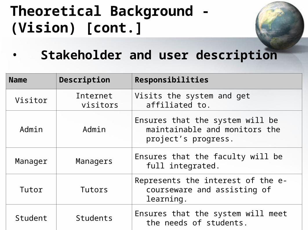
Name Description Responsibilities
Visitor Internet visitors Visits the system and get affiliated to.
Admin AdminEnsures that the system will be maintainable
and monitors the project’s progress.
Manager Managers Ensures that the faculty will be full integrated.
Tutor TutorsRepresents the interest of the e-courseware
and assisting of learning.
Student StudentsEnsures that the system will meet the needs of
students.
• Stakeholder and user description
Theoretical Background - (Vision) [cont.]
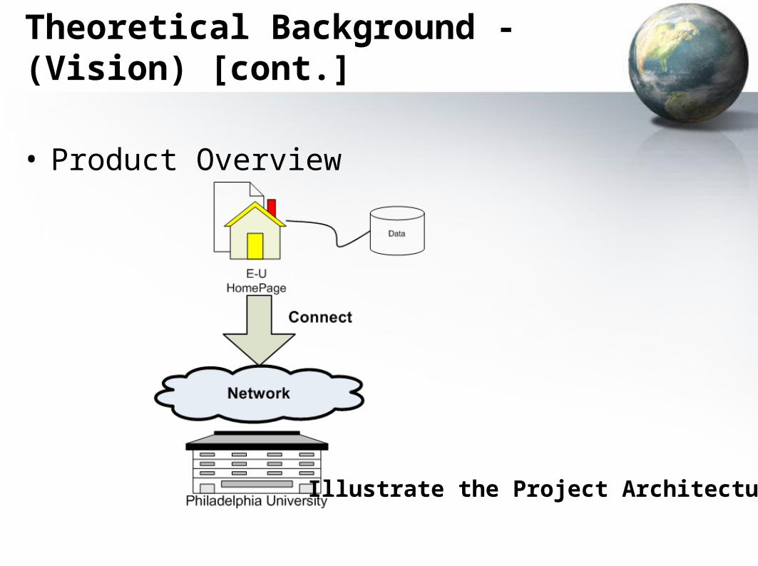
• Product Overview
Illustrate the Project Architecture
Theoretical Background - (Vision) [cont.]
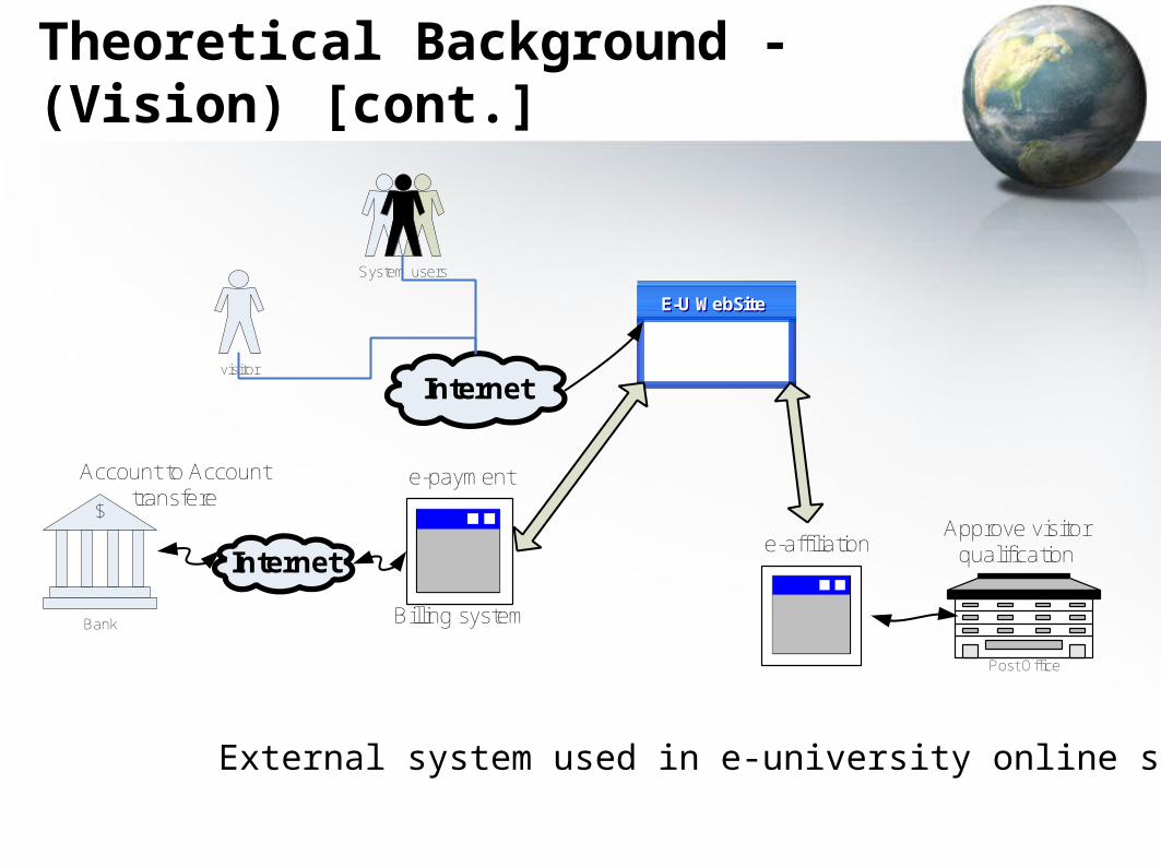
$
Bank
visitor
System users
Internet
Account to Account transfere
e-payment
Billing system
e-affiliation
E-U WebSiteE-U WebSite
Post Office
Approve visitor qualificationInternet
External system used in e-university online system
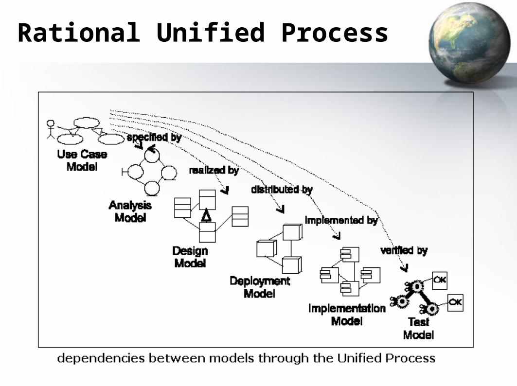
Rational Unified Process
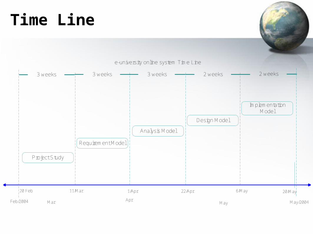
Time Line
Project Study
20 Feb 11/Mar
Feb/2004 Mar May May/2004
e-university online system Time Line
1/Apr 22/Apr 6/May
3 weeks
20/May
Implementation Model
Design Model
Analysis Model
Requirement Model
3 weeks3 weeks 2 weeks2 weeks
Apr
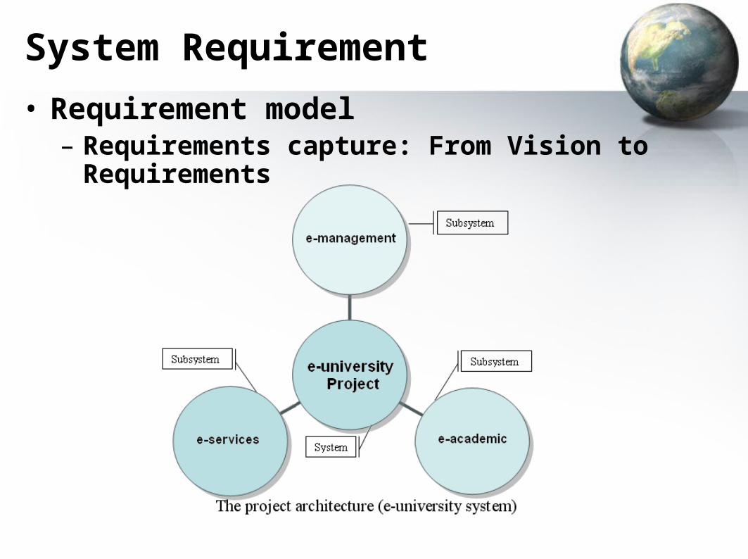
System Requirement
• Requirement model– Requirements capture: From Vision to
Requirements
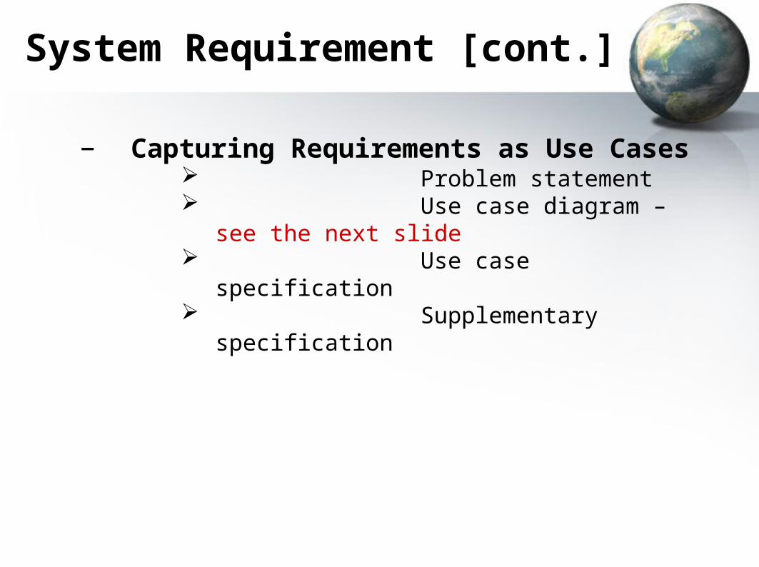
System Requirement [cont.]
– Capturing Requirements as Use Cases Problem statement Use case diagram – see the
next slide Use case specification Supplementary specification
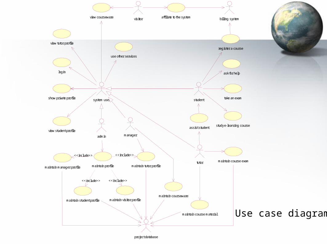
maintain manager profile
maintain student profile maintain visitor profile
project database
maintain courseware
maintain tutor profile
manager
maintain profile
admin
<<include>>
<<include>> <<include>>
<<include>>
maintain course exam
maintain course material
affiliate to the systemvisitor
tutor
billing system
assist student
ask for help
take an exam
register a course
student
study e-leanring course
use other services
login
show private profile
view tutor profile
view courseware
view student profile
system user
Use case diagram
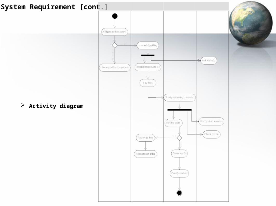
System Requirement [cont.]
Activity diagram
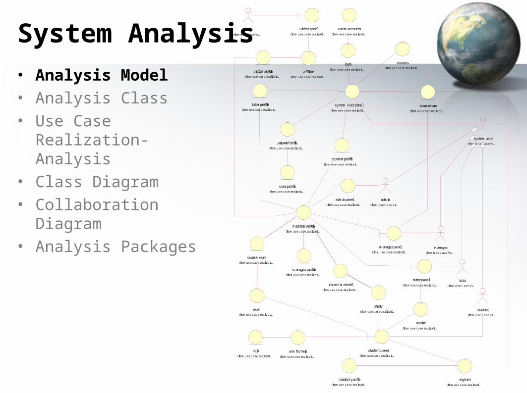
System Analysis
• Analysis Model • Analysis Class• Use Case Realization-
Analysis• Class Diagram• Collaboration Diagram• Analysis Packages
visitor
(from Use Case Vi...
visitor panel
(from use case realizati...
admin
(from Use Case Vi...
affiliate
(from use case realizati...
tutor
(from Use Case Vi...
users accounts
(from use case realizati...
user profile
(from use case realizati...
manager profile
(from use case realizati...
admin panel
(from use case realizati...
visitor profile
(from use case realizati...
help
(from use case realizati...
tutor panel
(from use case realizati...
course exam
(from use case realizati...
course material
(from use case realizati...
system user
(from Use Case Vi...
login
(from use case realizati...
tutor profile
(from use case realizati...
student profile
(from use case realizati...
privateProfile
(from use case realizati...
services
(from use case realizati...
manager
(from Use Case Vi...
maintain profile
(from use case realizati...
ask for help
(from use case realizati...
student
(from Use Case Vi...
assist
(from use case realizati...
exam
(from use case realizati...
study
(from use case realizati...
system user panel
(from use case realizati...
manager panel
(from use case realizati...
student profile
(from use case realizati...
student panel
(from use case realizati...
courseware
(from use case realizati...
register
(from use case realizati...
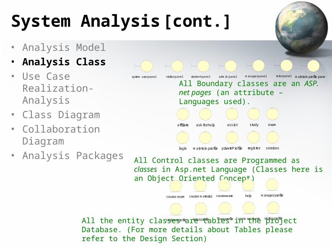
System Analysis [cont.]
• Analysis Model • Analysis Class• Use Case Realization-
Analysis• Class Diagram• Collaboration Diagram• Analysis Packages
admin panel manager panelstudent panelsystem user panel visitor panel tutor panel maintain profile panel
All Boundary classes are an ASP. net pages (an attribute – Languages used).
affiliate ask for help assist exam
login maintain profile privateProfile register services
study
All Control classes are Programmed as classes in Asp.net Language (Classes here is an Object Oriented Concept)
course exam course material courseware help manager profile
student profile tutor profile user profile users accounts visitor profile
All the entity classes are tables in the project Database. (For more details about Tables please refer to the Design Section)
System Analysis [cont.]
• Analysis Model • Analysis Class• Use Case Realization-
Analysis• Class Diagram• Collaboration Diagram• Analysis Packages
affiliate to the system
(from Use Case View)
affiliatevisitor panel visitor profile
ask for help
(from Use Case View)
ask for help helpstudent panel
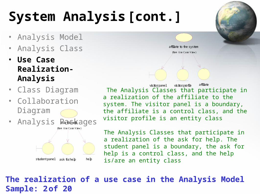
The Analysis Classes that participate in a realization of the affiliate to the system. The visitor panel is a boundary, the affiliate is a control class, and the visitor profile is an entity class
The Analysis Classes that participate in a realization of the ask for help. The student panel is a boundary, the ask for help is a control class, and the help is/are an entity class
The realization of a use case in the Analysis Model Sample: 2 of 20
System Analysis [cont.]
• Analysis Model • Analysis Class• Use Case Realization-
Analysis• Class Diagram• Collaboration Diagram• Analysis Packages
affiliate to the system use case
visitor profile
(f rom use case realization)
visitor
(f rom Use Case View)
affiliate
(f rom use case realization)
visitor panel
(f rom use case realization)
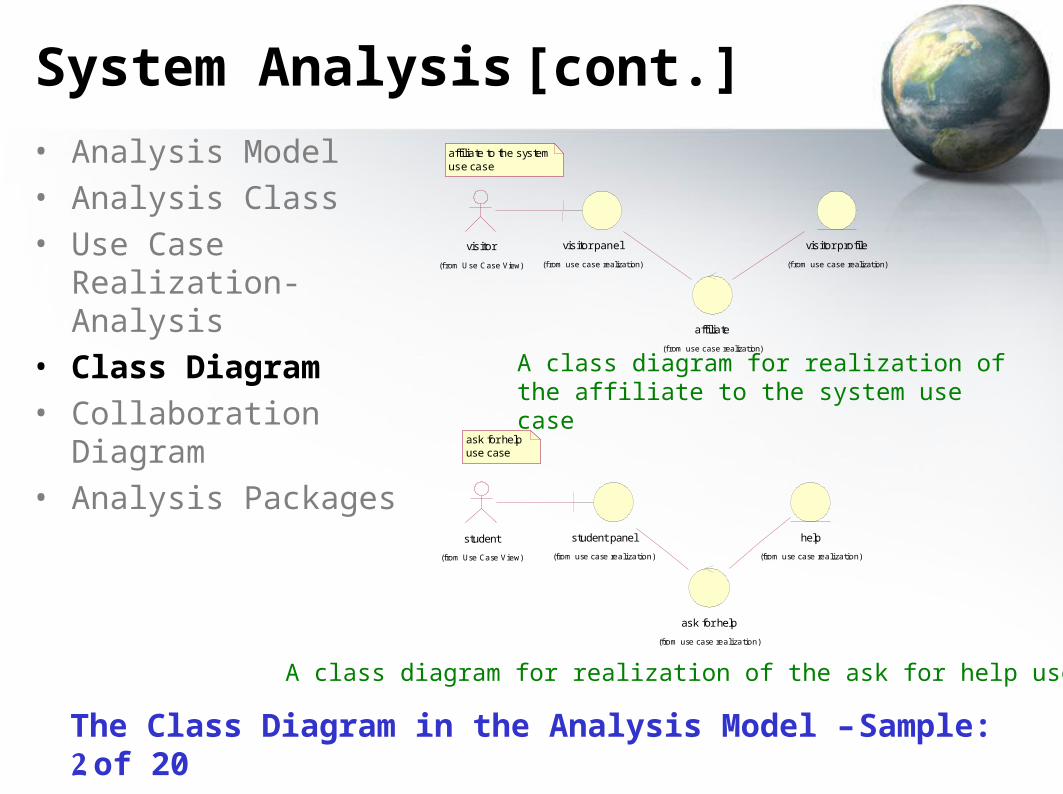
A class diagram for realization of the affiliate to the system use case
student
(from Use Case View)
student panel
(from use case realization)
help
(from use case realization)
ask for help
(from use case realization)
ask for help use case
A class diagram for realization of the ask for help use case
The Class Diagram in the Analysis Model – Sample: 2 of 20
System Analysis [cont.]
• Analysis Model • Analysis Class• Use Case Realization-
Analysis• Class Diagram• Collaboration Diagram• Analysis Packages
affiliate to the system
: visitor panel : visitor profile
: affiliate
: visitor
: student profile
: admin panel : admin
3: validate form info
5: send confirm email9: approve or disapprove affiliation
4: save info
10: create new student profile
1: browse2: complete form6: reply with email
8: decide affiliation
7: check affiliation
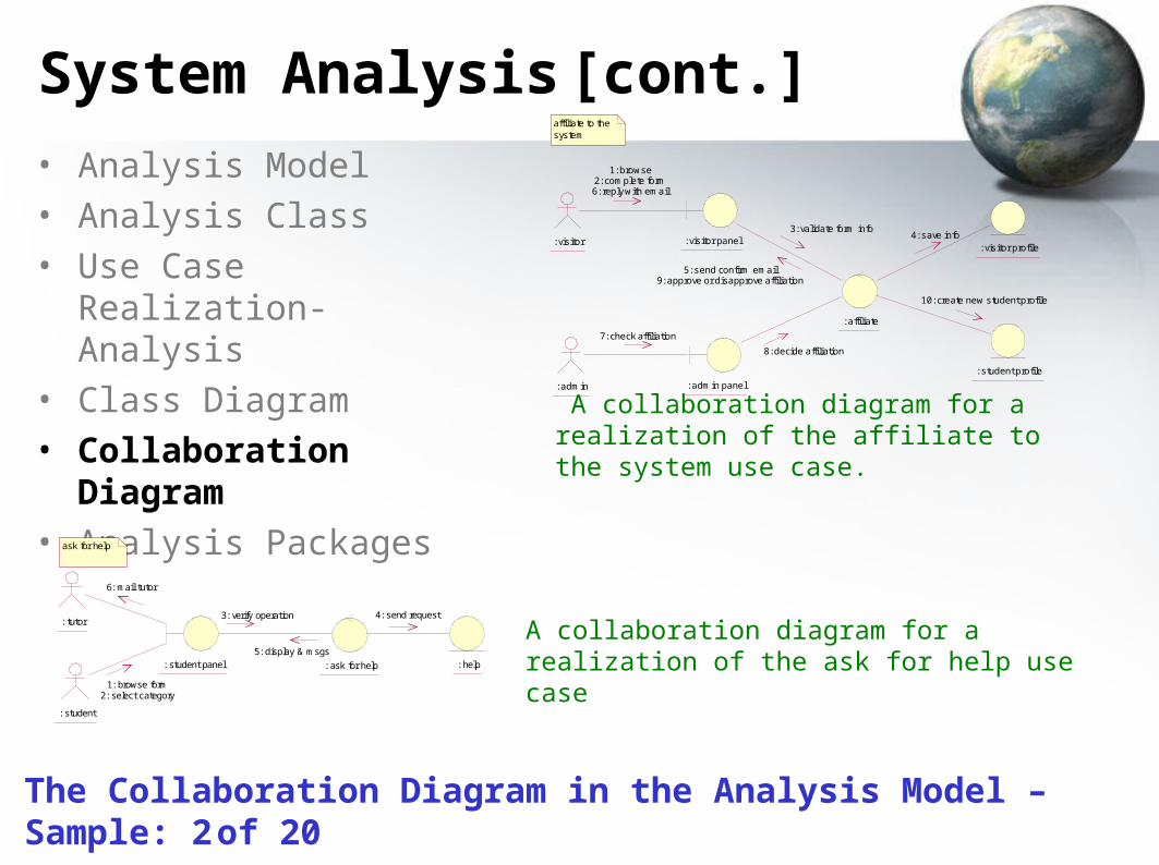
A collaboration diagram for a realization of the affiliate to the system use case.
ask for help
: student panel : ask for help : help
: student
: tutor3: verify operation
5: display & msgs
4: send request
1: browse form2: select category
6: mail tutor
A collaboration diagram for a realization of the ask for help use case
The Collaboration Diagram in the Analysis Model – Sample: 2 of 20
System Analysis [cont.]
• Analysis Model • Analysis Class• Use Case Realization-
Analysis• Class Diagram• Collaboration Diagram• Analysis Packages
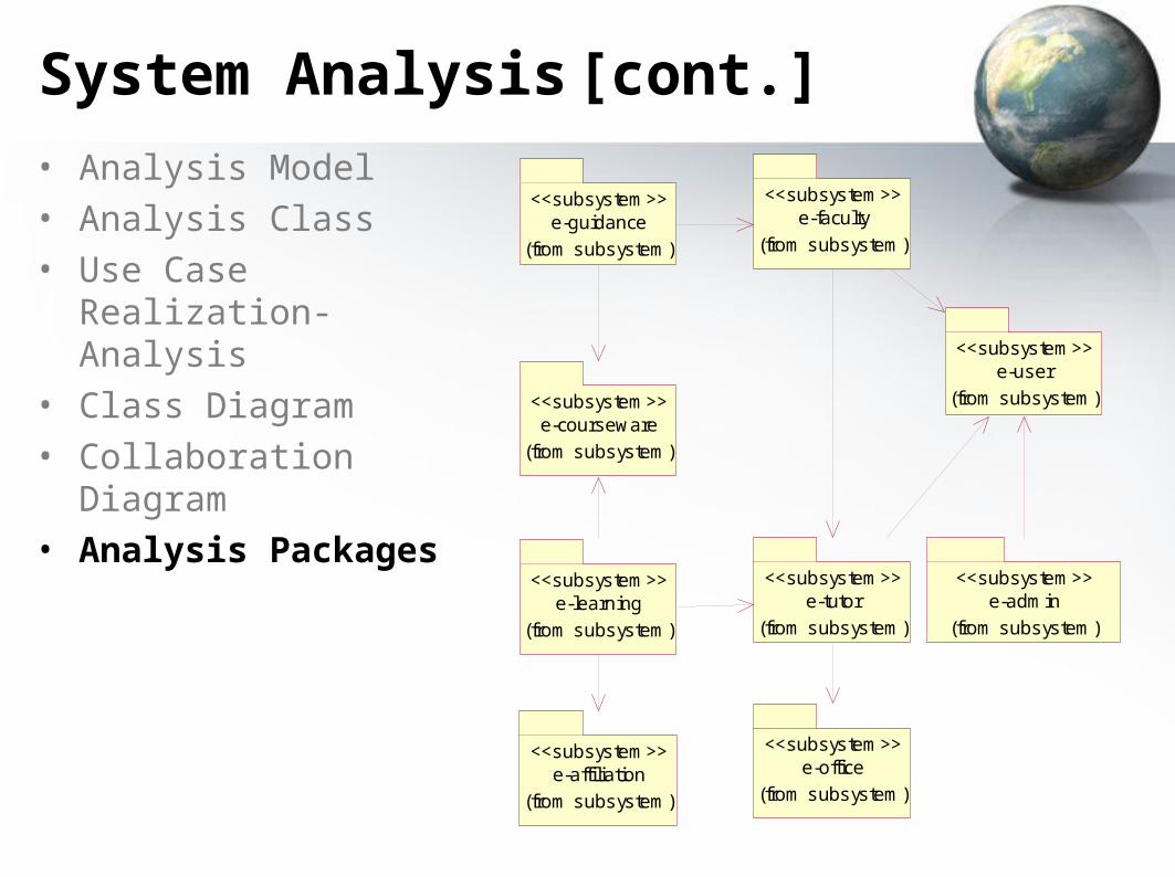
e-affiliation<<subsystem>>
(from subsystem)
e-courseware<<subsystem>>
(from subsystem)
e-faculty<<subsystem>>
(from subsystem)e-guidance
<<subsystem>>
(from subsystem)
e-tutor<<subsystem>>
(from subsystem)e-learning
<<subsystem>>
(from subsystem)
e-office<<subsystem>>
(from subsystem)
e-admin<<subsystem>>
(from subsystem)
e-user
(from subsystem)
<<subsystem>>
System Design
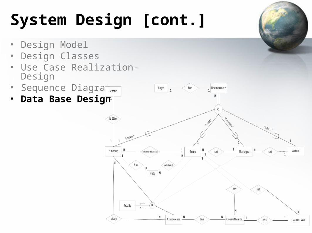
• Design Model • Design Classes• Use Case Realization- Design• Sequence Diagram• Data Base Design
The design model is an object model describing the realization of use cases,
and serves as an abstraction of the implementation model and its source
code. The design model is used as essential input to activities in
implementation and test.
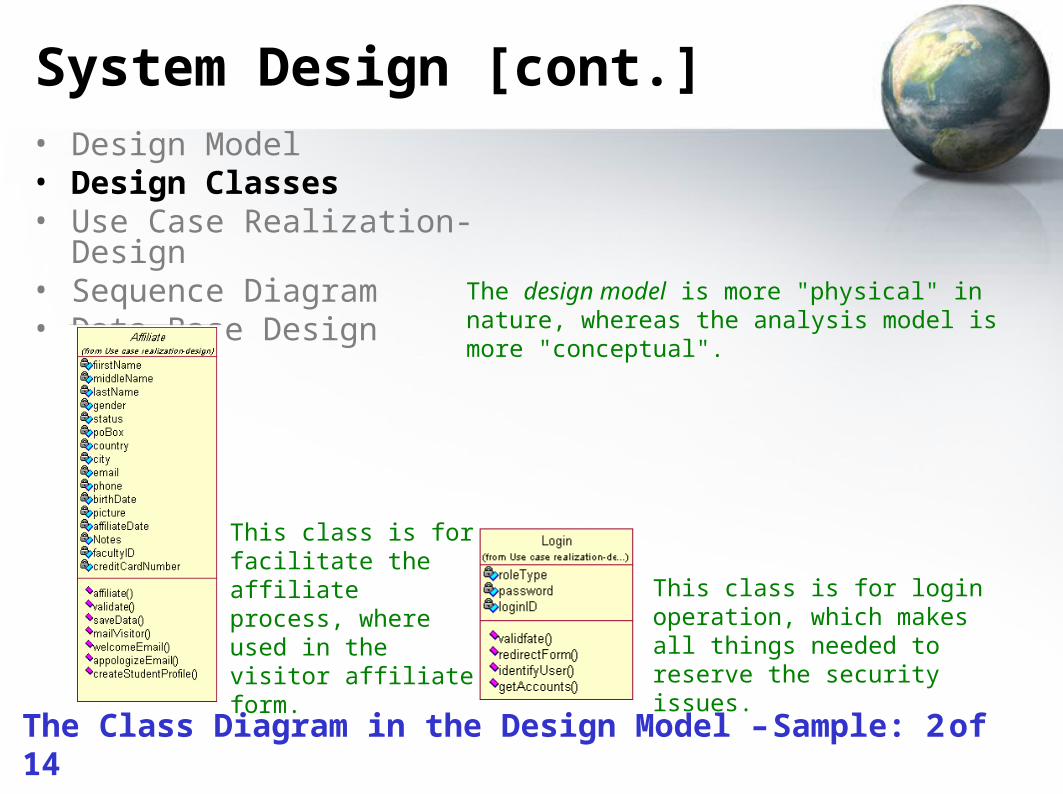
System Design [cont.]• Design Model • Design Classes• Use Case Realization- Design• Sequence Diagram• Data Base Design The design model is more "physical" in nature,
whereas the analysis model is more "conceptual".
This class is for facilitate the affiliate process, where used in the visitor affiliate form.
This class is for login operation, which makes all things needed to reserve the security issues.
The Class Diagram in the Design Model – Sample: 2 of 14

System Design [cont.]• Design Model • Design Classes• Use Case Realization- Design• Sequence Diagram• Data Base Design
managerProfi leUI
visitorProfileUI
studentProfileUI
tutorProfileUI
manager profile
(from use case realization)
student profi le
(from use case realization)
tutor profi le
(from use case realization)
maintain profile
(from use case realization)
admin panel
(from use case realization)
visitorProfile tutorProfilestudentProfilemanagerProfi lemaintainManagerProfi le
maintainVisitorProfi le
maintainStudentProfi le
maintainTutorProfi le
visitor profi le
(from use case realization)
e-admin subsystem
The Use Case Realization- Design in the Design Model – Sample: 2 of 8 subsystem
System Design [cont.]
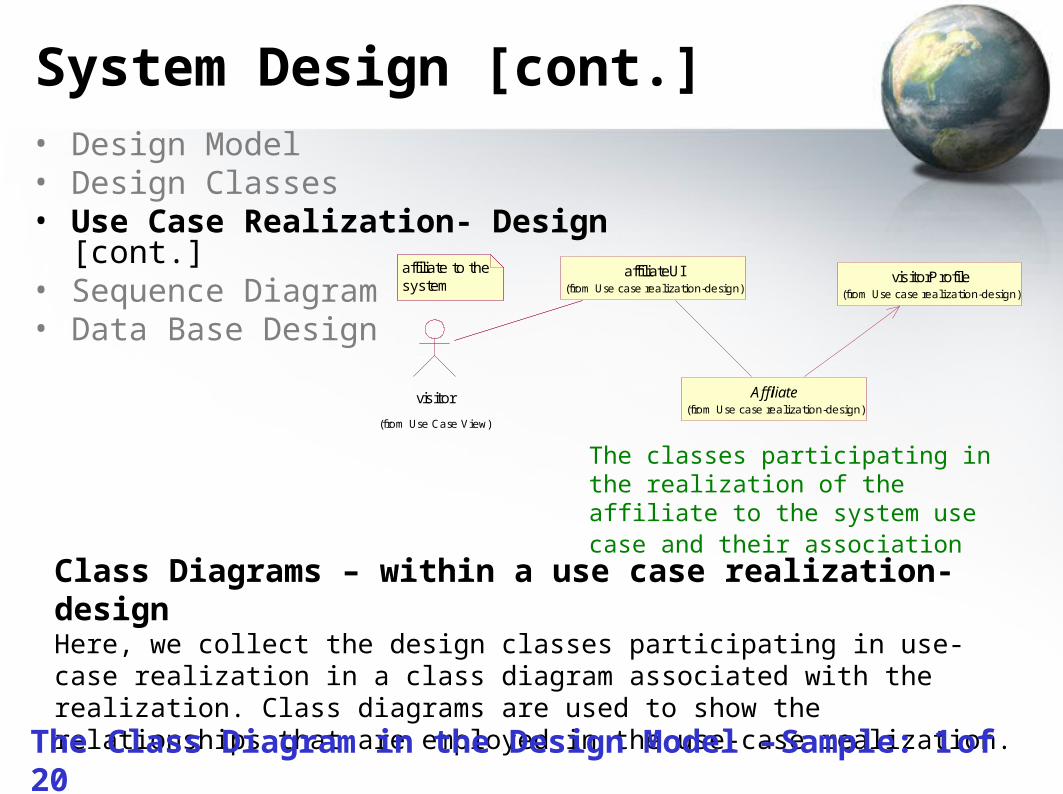
Class Diagrams – within a use case realization-designHere, we collect the design classes participating in use-case realization in a class diagram associated with the realization. Class diagrams are used to show the relationships that are employed in the use-case realization.
affiliate to the system
visitor
(from Use Case View)
visitorProfile(from Use case realization-design)
Affiliate(from Use case realization-design)
affiliateUI(from Use case realization-design)
The classes participating in the realization of the affiliate to the system use case and their association
The Class Diagram in the Design Model – Sample: 1 of 20
• Design Model • Design Classes• Use Case Realization- Design [cont.]• Sequence Diagram• Data Base Design
System Design [cont.]• Design Model • Design Classes• Use Case Realization- Design• Sequence Diagram• Data Base Design
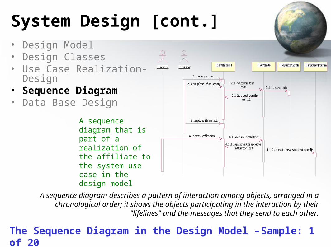
A sequence diagram describes a pattern of interaction among objects, arranged in a chronological order; it shows the objects participating in the interaction by their "lifelines"
and the messages that they send to each other.
: admin : visitor : affiliateUI : Affiliate : visitorProfile : studentProfile
1. browse form
2. complete form entry 2.1. validate form info 2.1.1. save info
2.1.2. send confirm email
3. reply with email
4. check affiliation 4.1. decide affiliation
4.1.1. approve/disapprove affiliation list 4.1.2. create bew student peofile
A sequence diagram that is part of a realization of the affiliate to the system use case in the design model
The Sequence Diagram in the Design Model – Sample: 1 of 20
System Design [cont.]
• Design Model • Design Classes• Use Case Realization- Design• Sequence Diagram• Data Base Design
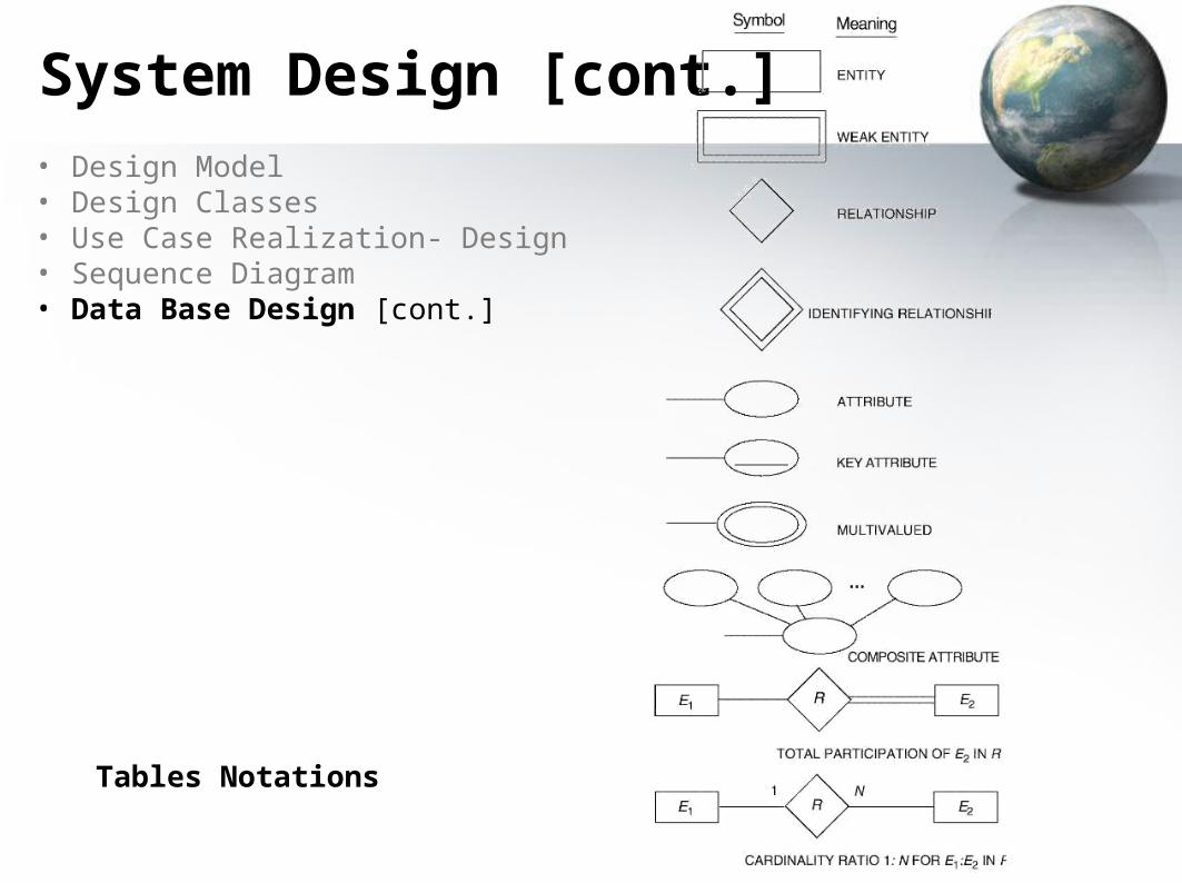
System Design [cont.]• Design Model • Design Classes• Use Case Realization- Design• Sequence Diagram• Data Base Design [cont.]
Tables Notations
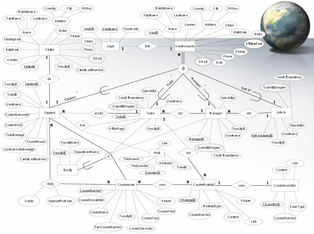
Login UserAccounts
Student
Visitor
Tutor Admin
faculty
Manager
Courseware CourseMaterial
d
setset
study
be
assist
set
uses
U
CourseQuestionuses
Into
UserID
FirstName LastName
MiddleName Country City
Gender
BirthDate
Picture
Phone
Name
Address
Notes
AffiliateDate
Role
PassWordLoginID UserName
VisitorID
FirstName LastName
MiddleNameCountry City
Gender
BirthDate
Picture
Phone
Name
Address
Notes
StartingDate
FacultyID StudentID
TutorID
UserName
CurrentSemester
CurrentYear
LastSemesterAverage
TotalAverage
Grade AppeardForExam
CourseNumber
CourseName
Pre-CourseNumber
FacultyIDCourseYear
CourseSemester
CourseYear
Picture CMaterialID
CourseNumberContent
MaterialType
Link
Picture
Content
Link
CQuestionID
CourseNumber
ExamType
FacultyID
FacultyName
DepartmentName
AdministratorID
FacultyID
ScientificDegree
YearOfExperience
Specialize
UserName
TutorID
FacultyID
ScientificDegree
YearOfExperience
Specialize
UserName
OfficePage
ManagerID
ScientificDegree
YearOfExperience
UserName
Specialize
FacultyID
1 1
M
1 1 1 1
1MM 11M
1
1
M
N M N
1
M
1 1
“Student”
“Manager” “Admin"
“Tut
or”
Status
POBoxPOBox
FacultyID
Status
CreditCardNumber
CreditCardNumber
PassedHours
CourseDescription
Help
Ask
TheAnswer
TheQuestion
Link
TutorID
QuestionID
Achieved
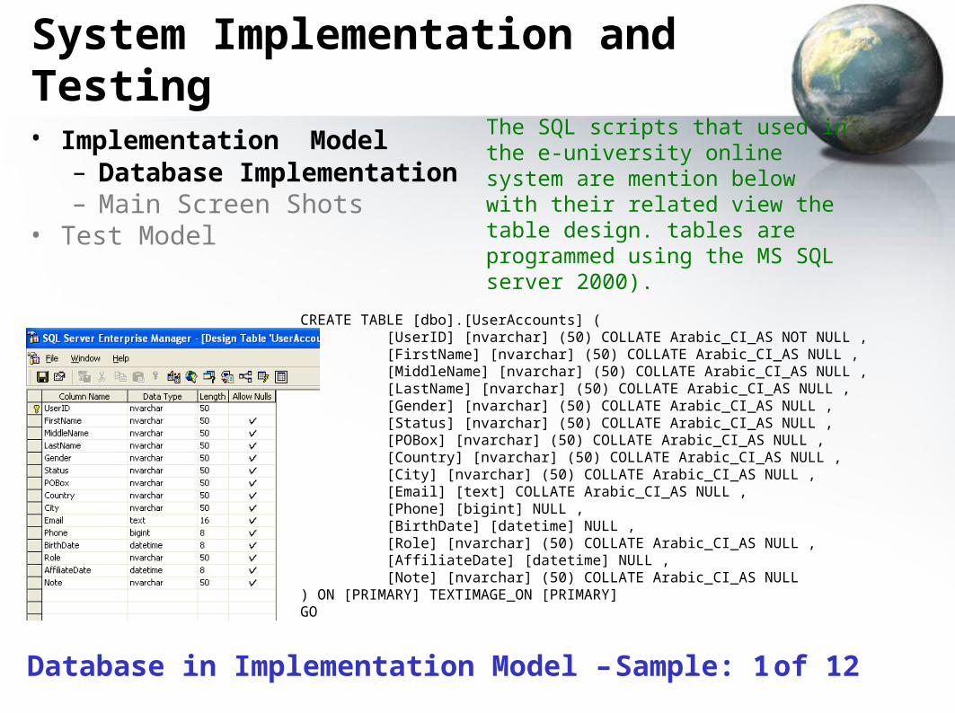
System Implementation and Testing
• Implementation Model – Database Implementation– Main Screen Shots
• Test Model
The SQL scripts that used in the e-university online system are mention below with their related view the table design. tables are programmed using the MS SQL server 2000).
CREATE TABLE [dbo].[UserAccounts] ([UserID] [nvarchar] (50) COLLATE Arabic_CI_AS NOT NULL ,[FirstName] [nvarchar] (50) COLLATE Arabic_CI_AS NULL ,[MiddleName] [nvarchar] (50) COLLATE Arabic_CI_AS NULL ,[LastName] [nvarchar] (50) COLLATE Arabic_CI_AS NULL ,[Gender] [nvarchar] (50) COLLATE Arabic_CI_AS NULL ,[Status] [nvarchar] (50) COLLATE Arabic_CI_AS NULL ,[POBox] [nvarchar] (50) COLLATE Arabic_CI_AS NULL ,[Country] [nvarchar] (50) COLLATE Arabic_CI_AS NULL ,[City] [nvarchar] (50) COLLATE Arabic_CI_AS NULL ,[Email] [text] COLLATE Arabic_CI_AS NULL ,[Phone] [bigint] NULL ,[BirthDate] [datetime] NULL ,[Role] [nvarchar] (50) COLLATE Arabic_CI_AS NULL ,[AffiliateDate] [datetime] NULL ,[Note] [nvarchar] (50) COLLATE Arabic_CI_AS NULL
) ON [PRIMARY] TEXTIMAGE_ON [PRIMARY]GO
Database in Implementation Model – Sample: 1 of 12
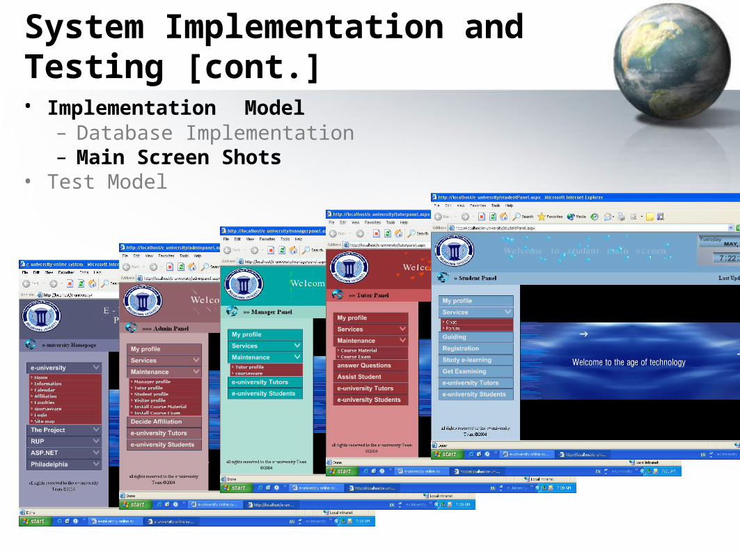
System Implementation and Testing [cont.]• Implementation Model
– Database Implementation– Main Screen Shots
• Test Model
System Implementation and Testing [cont.]• Implementation Model
– Database Implementation– Main Screen Shots
• Test Model
This project has been verified and validated to all measurement testing successfully
Result Discussion - (Conclusion & Future Work)
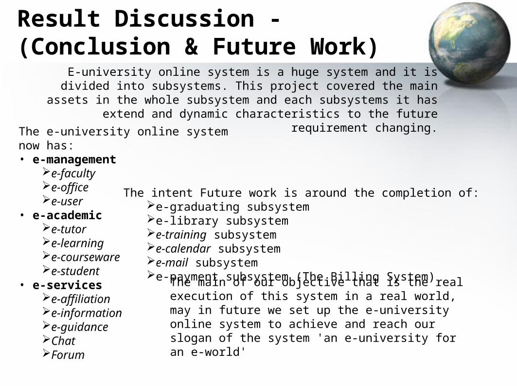
E-university online system is a huge system and it is divided into subsystems. This project covered the main assets in the whole subsystem and each
subsystems it has extend and dynamic characteristics to the future requirement changing.
The e-university online system now has:• e-management
e-facultye-office e-user
• e-academice-tutore-learninge-coursewaree-student
• e-servicese-affiliatione-informatione-guidanceChatForum
The intent Future work is around the completion of:e-graduating subsysteme-library subsysteme-training subsysteme-calendar subsysteme-mail subsysteme-payment subsystem (The Billing System)
The main of our objective that is the real execution of this system in a real world, may in future we set up the e-university online system to achieve and reach our slogan of the system 'an e-university for an e-world'
Glossary
• EUOS : E-University Online System
• V.S.NET : Visual Studio .Net
• RUP : Rational Unified Process
• ASP : Active Server Pages
• DB : Database
References
• [REF: 1] I.Jacobson, G.Booch, J.Rumbaugh, Rational Software corporation "The Unified Software development Process", AddisonWesley 1999.
• [REF: 2] Elmasri, Navathe, "Fundamentals of Database Systems", 3rd Edition 2000,
• [REF: 3] Ian Sommerville, "Software Engineering", AddisonWesley
• 6th Edition 2001.• [REF: 4] MSDN Library for Visual Studio .NET 2003, a soft copy.• [REF: 5] Rational Unified Process, Soft Copy , installed with
Rational Suite Enterprise 2000.Electronic References• [REF: 6] http://www.dlcoursefinder.com• [REF: 7] http://www.asp.net
Special Thanks to:Chairman & Member of Approval
Committee Spirit of the team unitySupervisor Dr. Nabeel M. Bani
HaniPhiladelphia University – Jordan
e-university online system
an e-university for an e-world
http://E-University.cjb.net