Embed Size (px)
Citation preview
E. U. Rafailov
Optoelectronics and Biomedical Photonics Group School of Engineering and Applied Science
Aston University Aston Triangle Birmingham
UK

Quantum Dot materials
InAs/GaAs Quantum Dot edge-emitting lasers
Continuous wave regime
Mode-locked regime
Second-harmonic generation of QD edge-emitting
lasers
VECSELs
Second-harmonic generation of VECSELs
Biophotonics applications
Conclusions
Outline

Quantum-dots structures
E
D(E)
EC
D(E)
E EC
D(E)
E EC
Bulk Quantum Well Quantum Dot
Density of states
Schematic morphology
3 / 41

Quantum-dots for ultrafast devices
D(E)
E EC
Quantum Dot
Broad gain bandwidth
Ultrafast carrier dynamics
Low threshold current
Low temperature sensitivity
Lower absorption saturation fluence
QD-SESAMs
Great potential in THz radiation
4 / 41

InAs/GaAs Quantum Dot lasers
Figure courtesy of
E.U. Rafailov et al., Nature Photonics, 1, p. 395, 2007 5 / 41
Ultra-broad electroluminescence spectra of
a specially designed QD device
Low light absorption and minimal scattering
in human tissue in 1 – 1.3 µm range

InAs/GaAs QD tunable laser
• 4 mm length, 5 µm wide waveguide
• 10 layers InAs QDs, grown on GaAs substrate
• waveguide angled at 5o
• facets AR coated: Rangled < 10-5
Rfront ~ 2 ·10-3
High-power CW external cavity InAs/GaAs quantum-dot diode laser
with a tuning range of 202 nm (between 1122 nm and 1324 nm)
K.A. Fedorova et al., Opt. Express, 18(18), p. 19438, 2010 6 / 41

Spectral characteristics
A tuning range of 202nm was achieved with the QD laser.
Max Output Power @10oC, 1700mA:
W/O OC 500 mW (λ=1220nm)
20%OC 140 mW (λ=1150nm) 1210 1215 1220 1225 1230
-60
-50
-40
-30
-20
-10
0
Inte
nsit
y,
dB
m
Wavelength, nm
50 dB
0.13 nm
The results obtained show that the tuning range is mostly enhanced on the blue side of the
spectrum for lower temperatures and higher pump currents, whereas reducing the cavity losses
assists in the enhancement of the tuning range on the red side of the spectrum.
K.A. Fedorova et al., Opt. Express, 18(18), p. 19438, 2010 7 / 41

1160 1180 1200 1220 1240 1260 1280 1300
0
1000
2000
3000
4000
5000
6000
7000
8000
9000
10000
Offse
t Y
va
lue
s
Wavelength (nm)
36 mW, 16.32 THz
75 mW, 12.98 THz
98 mW, 8.96 THz
105 mW, 6.2 THz
107 mW, 2.9 THz
115 mW, 0.55 THz
Broadly tunable CW LD
Spectral characteristics
1170 1180 1190 1200 1210 1220 1230 1240 1250 1260
0
100
200
300
400
500
600
700
800
900
1000
Optical Spectrum BBQDLD Double littrow
Inte
nsity (
a.u
.)
Wavelength (nm)
Tunable QD Diode Laser, 30 mW
0 5 10 15 20 25 30 35 40 45 50
20
25
30
35
40
45
50
55
60
65
70
75
80
85
90
95
100
105
110
115
120
THz Output Trend, 25-layer QD Structure with 5um Gap Antenna
Pumped by Tunable InAs:GaAs QD Laser Diode
LIA
Sig
(u
V)
PCA Bias (V)
30 mW Tunable QDLD Pump
Polynomial Fit of LIA Sig

SHG in a periodically poled KTP waveguide
PPKTP crystal used in this work
• 16 mm length
• facets not AR coated
• waveguide with cross-sectional area of ~4×4 μm2
• periodically poled for SHG at ~1183 nm
(poling period ~12.47 µm)
• refractive index step Δn≈0.01
Both the pump laser and the crystal
were operating at room temperature
K.A. Fedorova et al., Laser Physics Letters, 9(11), p. 790, 2012 9 / 41

Blue-to-Red tunable SHG
Dependence of SHG and launched pump power on
wavelength over 478 nm – 652 nm wavelength range
K.A. Fedorova et al., CLEO/Europe-EQEC, CD-6.3, 2013 10 / 41
567 nm
K.A. Fedorova et al., Laser Physics Letters, 9(11), p. 790, 2012

SHG at 561 nm from a PPLN waveguide
Figure courtesy of
5% MgO-doped Y-cut congruent lithium niobate
• Dimensions: 10 mm (L) x 0.5 mm (W) x 1.5 mm (T)
• Facets optically polished at ~5.4o
• AR coating at 1122 nm (R<0.5%) & at 561 nm
(R<1%) on both input/output facets
• Cross-sectional area of the waveguide is ~ 4 x 5 µm2
K.A. Fedorova et al., CLEO/Europe-EQEC, CD-P.21, 2013 11 / 41
Max SHG Power 90 mW
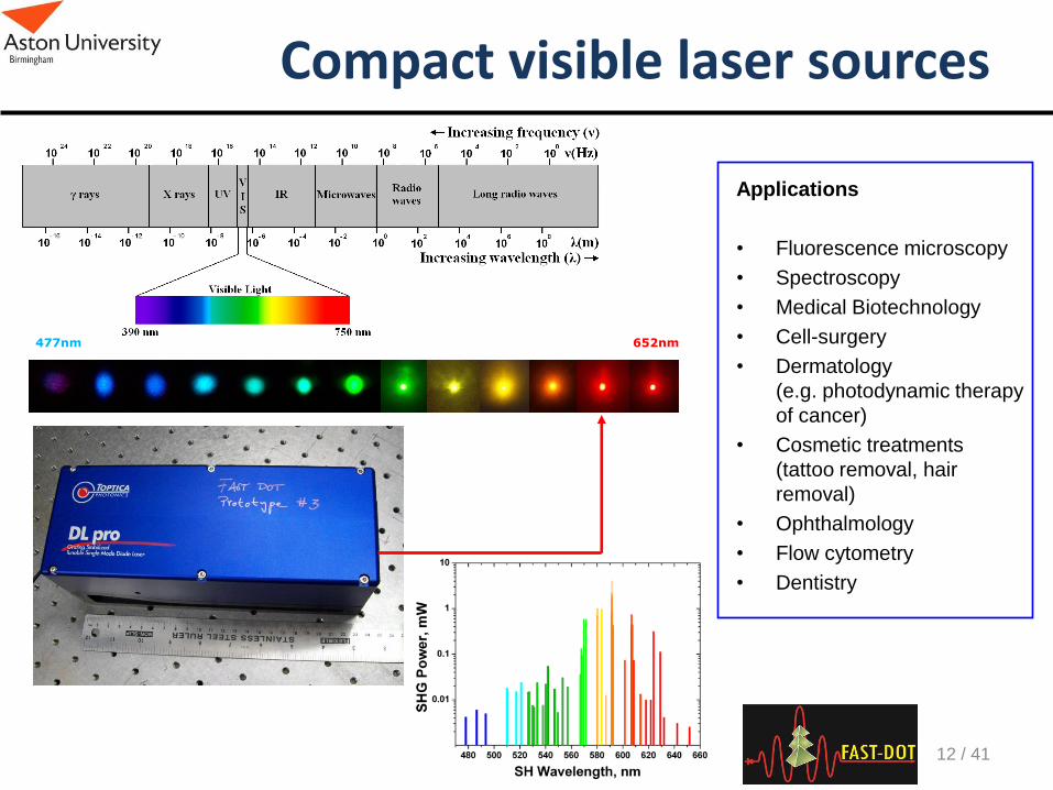
Compact visible laser sources
477nm 652nm
Applications
• Fluorescence microscopy
• Spectroscopy
• Medical Biotechnology
• Cell-surgery
• Dermatology
(e.g. photodynamic therapy
of cancer)
• Cosmetic treatments
(tattoo removal, hair
removal)
• Ophthalmology
• Flow cytometry
• Dentistry
12 / 41
Mode-locked QD laser
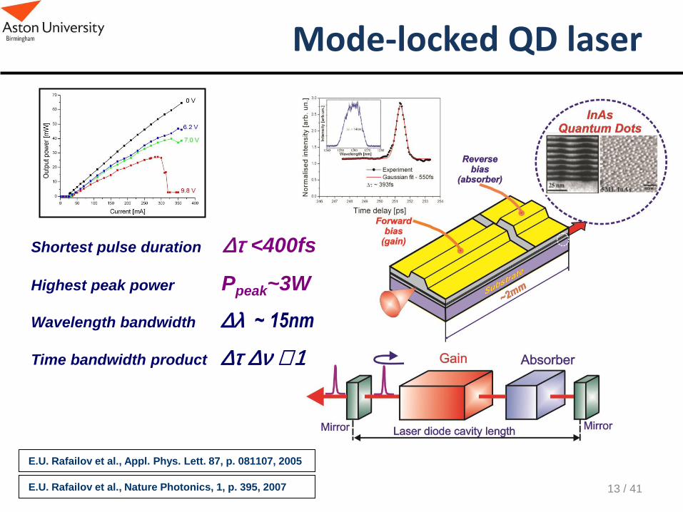
Shortest pulse duration Dt <400fs
Highest peak power Ppeak~3W
Wavelength bandwidth Dl ~ 15nm
Time bandwidth product Dt Dn ~ 1
E.U. Rafailov et al., Nature Photonics, 1, p. 395, 2007
E.U. Rafailov et al., Appl. Phys. Lett. 87, p. 081107, 2005
13 / 41

InAs/GaAs QD mode-locked tunable laser
• 10 non-identical InAs QD layers,
grown on GaAs substrate
• 4 mm length, 800 µm saturable absorber
• 6 µm wide waveguide
• waveguide angled at 7o
• facets AR coated: Rangled < 10-5
Rfront ~ 10-2
Gain Chip
14 / 41
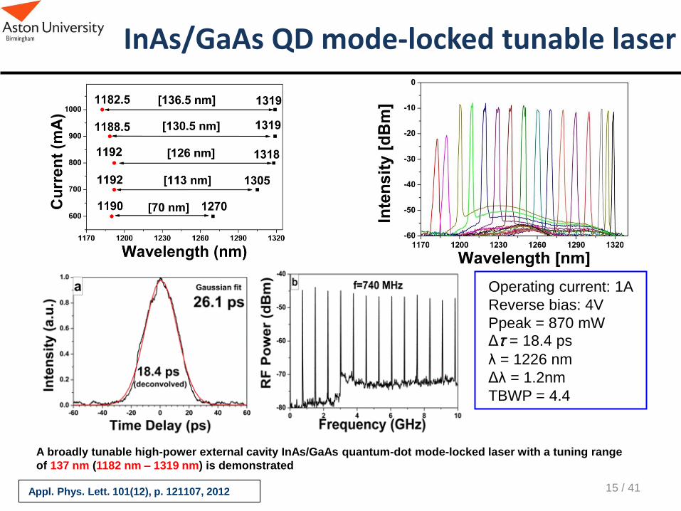
Operating current: 1A
Reverse bias: 4V
Ppeak = 870 mW
Δt = 18.4 ps
λ = 1226 nm
Δλ = 1.2nm
TBWP = 4.4
A broadly tunable high-power external cavity InAs/GaAs quantum-dot mode-locked laser with a tuning range
of 137 nm (1182 nm – 1319 nm) is demonstrated
Appl. Phys. Lett. 101(12), p. 121107, 2012 15 / 41
InAs/GaAs QD mode-locked tunable laser

Broad Repetition-Rate Tunable QD-ECMLL
16 / 41 Appl. Phys. Express, 4, p. 062703, 2011
Broad repetition-rate tunable QD-ECMLL
demonstrated frequency tuning range from
1 GHz to a record-low value of 191 MHz
(The corresponding total optical cavity
length varied from 15 to 78.5 cm) The peak power remains nearly constant under certain
operation conditions (especially at a low gain current and
a high reverse bias), with different pulse repetition rates

Orange-to-Red tunable picosecond SHG
K.A. Fedorova et al., Optics Letters, 38(15), p. 2835, 2013 17 / 41

QD Tapered Lasers
18 / 41
Paver = 288 mW; Ppeak= 17.7 W; λ ~ 1260 nm;
Δt ~ 672 fs; Δλ = 2.8 nm; f ~ 16 GHz
Taper
section
Absorber
section
QD layers
800 µm
3.2 mm
2˚
HR coating
AR coating 10 layers of InAs QDs
Gain peak: ~1.26 µm
Laser Physics, 22(4), p. 715, 2012

Broadly tunable QD-based MOPA
19 / 41
IEEE Phot. Tech. Lett. 24(20), p.1841, 2012
Schematics of a master-oscillator power-amplifier
Gain chip current: 600 mA Reverse bias: 0 – 6 V SOA current: 2185 mA
Demonstration of a 96-nm tunable (between 1187 nm and 1283 nm) MOPA
picosecond optical pulse system formed by an QD-ECMLL and a tapered
SOA with 4.39-W peak power under fundamental mode-locked operation
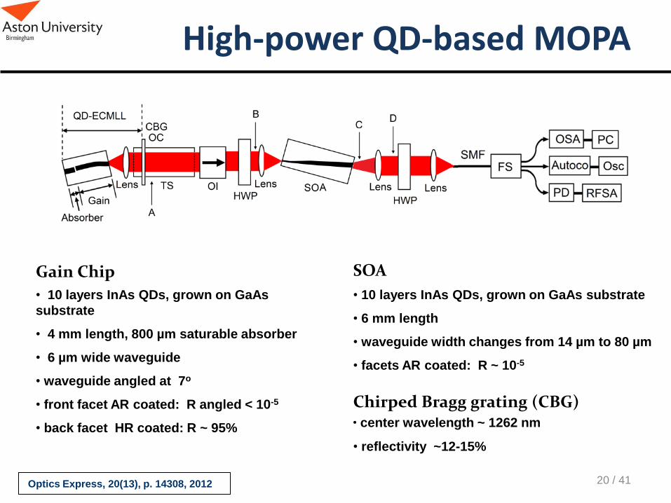
High-power QD-based MOPA
Optics Express, 20(13), p. 14308, 2012
• 10 layers InAs QDs, grown on GaAs
substrate
• 4 mm length, 800 µm saturable absorber
• 6 µm wide waveguide
• waveguide angled at 7o
• front facet AR coated: R angled < 10-5
• back facet HR coated: R ~ 95%
Gain Chip
• 10 layers InAs QDs, grown on GaAs substrate
• 6 mm length
• waveguide width changes from 14 µm to 80 µm
• facets AR coated: R ~ 10-5
SOA
Chirped Bragg grating (CBG) • center wavelength ~ 1262 nm
• reflectivity ~12-15%
20 / 41
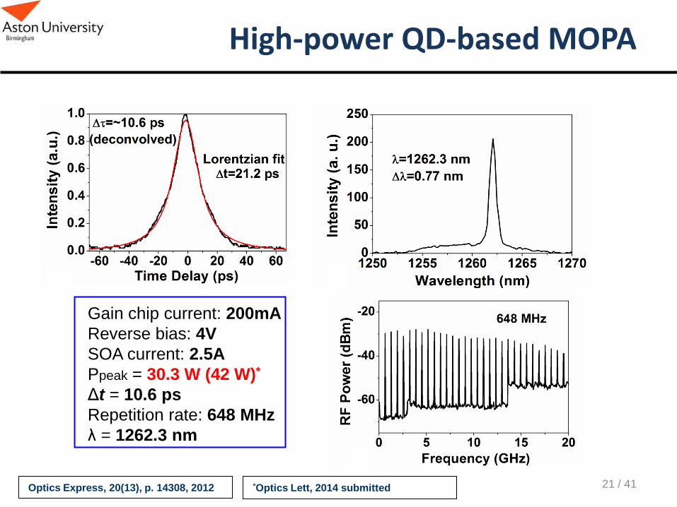
High-power QD-based MOPA
Optics Express, 20(13), p. 14308, 2012
Gain chip current: 200mA
Reverse bias: 4V
SOA current: 2.5A
Ppeak = 30.3 W (42 W)*
Δt = 10.6 ps
Repetition rate: 648 MHz
λ = 1262.3 nm
21 / 41 *Optics Lett, 2014 submitted

Compact QD laser sources
Applications
• Fluorescence microscopy
• Spectroscopy
• Optical coherence
tomography
• Cell-surgery
• Dermatology (e.g.
photodynamic therapy
of cancer)
• Cosmetic treatments (tattoo
removal, hair removal)
• Ophthalmology
• Dentistry
• Blood analysis
• Frequency-conversion
1122 nm – 1324 nm
Up to 500 mW in CW
1182 nm – 1319 nm
Up to 4.39 W pulsed
(1.3GHz, 15-20ps)
Up to 30.3 W pulsed
(648MHz, 10.6ps)
Down to 191 MHz rep. rate
672 fs pulse duration
22 / 41

500 600 700 800 900 1000 1100 1200 1300
0.1
1
10
Butkus et al., 2010
Rautiainen et al., 2010
Butkus et al., 2011
Schlosser et al., 2009
Germann et al., 2008
Butkus et al., 2011
Rautiainen et al., 2010 [32]
Albrecht et al., 2010 [27]
Butkus et al., 2010 [33]
Lott et al., 2005 [25]
Hoffmann et al., 2010
CW
outp
ut pow
er
(W)
Wavelength (nm)
QD Semiconductor Disk Laser (SDL)
23 / 41
Vertical External Cavity Surface Emitting Laser (VECSEL)
Low light absorption and minimal scattering
in human tissue in 1 – 1.3 µm range

6 W (8W*) CW from QD gain at 1040nm
M. Butkus et al., IEEE J. Sel. Top. Quant. Electron., 17, p. 1763, 2011 24 / 41 *IEEE Phot.Tech.Lett, 26, p. 1565, 2014
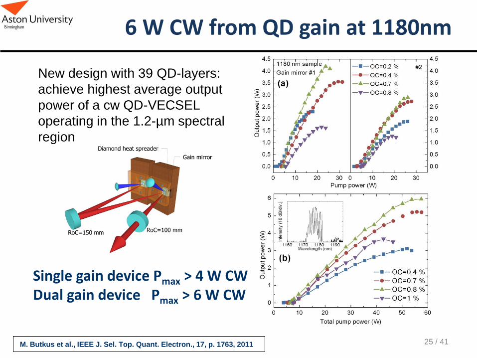
6 W CW from QD gain at 1180nm
Single gain device Pmax > 4 W CW Dual gain device Pmax > 6 W CW
New design with 39 QD-layers:
achieve highest average output
power of a cw QD-VECSEL
operating in the 1.2-µm spectral
region
M. Butkus et al., IEEE J. Sel. Top. Quant. Electron., 17, p. 1763, 2011 25 / 41

1.6 W CW from QD gain at 1260nm
New design with 39 QD-layers: achieve highest average output power
of a cw QD-VECSEL operating in the 1.26-µm spectral region
•Pmax 1.6 W CW •M2 ~1.1 up to 0.8 W
M. Butkus et al., IEEE J. Sel. Top. Quant. Electron., 17, p. 1763, 2011 26 / 41

Tunable QD-SDL
Dl ~60nm at 1030nm
Dl ~69nm at 1180nm
Dl ~25nm at 1260nm
M. Butkus et al., IEEE J. Sel. Top. Quant. Electron., 17, p. 1763, 2011 27 / 41

M. Butkus et al., IEEE J. Sel. Top. Quant. Electron., 17, p. 1763, 2011
Intracavity SHG in QD VECSEL
SHG power:
2 W (514 nm)
2.5 W (590 nm)
0.33 W (624 nm)
28 / 41

29 / 41
Recent development of mode-locked SDLs with QD technology

Mode-locked SDL
Mode-lock SDL with QW gain and using
QD SESAM
• λ = 1027.5 nm
• Room temperature operation (20oC)
• Output power: 45.5 mW
• Pulse duration: 870 fs
• Repetition rate: 896 MHz
Gain:
• 6 layers of QW
SESAM:
• 5 QD layers
30 / 41 Appl. Phys. Lett., 94, p. 251105, 2009
• Output power: > 1 W
• Pulse duration < 1.5 ps
• Repetition rate: 500 MHz
Mode-lock SDL with QW gain and using
QD SESAM
• λ = 965 nm
• Room temperature operation (20oC)

Ultra-low repetition rate mode-locked SDL
M. Butkus et al., IPC-2013, WE2.3, 2013
Ultra low repetition rate of 85.7 MHz is
demonstrated in mode-locked semiconductor
disk laser overcoming short carrier lifetime
limitations. It is shown that fundamental mode-
locking in such long cavity is supported by
phase-amplitude coupling.
31 / 41

Self-mode-locking in semiconductor lasers
Kornaszewski et al, Laser Photonics Rev., 6(6), L20, 2012
Gaafar et al, Opt. Lett., v.39(15), p. 4623-4626, 2014 32 / 41
ML observed in two configurations: • Soft aperture near stability limit • With hard aperture within
stability limits
200 400 600 800 1000 1200-65
-60
-55
-50
-45
-40
-35
-30
-25
Am
plit
ude (
dB
)
Frequency (MHz)
-4 -3 -2 -1 0 1 2 3 4
0.0
0.2
0.4
0.6
0.8
1.0
= 930 fs Data
sech2(t) fit
Inte
nsity (
a.u
.)
Time delay (ps)
RF frequency spectra:
Autocorrelation trace:
6.8kW peak power

33 / 41
Compact QD-VECSEL sources
Applications
• Fluorescence microscopy
• Spectroscopy
• Optical coherence
tomography
• Cell-surgery
• Dermatology (e.g.
photodynamic therapy
of cancer)
• Cosmetic treatments (tattoo
removal, hair removal)
• Ophthalmology
• Dentistry
• Blood analysis
• Frequency-conversion
Dl ~ 60 nm at 1030nm
Up to 6 W in CW at 1040 nm
Up to 2 W in CW at 514 nm
Dl ~ 69 nm at 1180nm
Up to 6 W in CW at 1180 nm
Up to 2.5 W in CW at 590nm
Dl ~ 25 nm at 1260nm
Up to 1.6 W in CW at 1270 nm
Up to 0.33 W in CW at 624nm
Up to 1 W in pulsed regime
Short pulse duration 870 fs
Ultra low repetition rate 85.7 MHz

34 / 41
Multi-photon Imaging
Single Photon Excitation: Lots of absorption everywhere, sample damage and no intrinsic sectioning Multi-Photon Excitation: Absorption/excitation only in focal volume, less damage, live sample imaging, 3-D scanning, longer wavelength=less scatter
f
f
tpef
Linear excitation
fluorescence
Two-photon
excitation
fluorescence
f e
signal
is NOT confined
signal
is confined
h e > h f h e < h f

Backwards
Forward
Combined
Body wall muscles (SHG)
GFP labelled neurons (two-photon
excited fluorescence - TPEF) SHG Imaging of Vulva Muscles
and body walls
C. Elegans
ICFO Barcelona
Multi-photon imaging with femtosecond laser
35 / 41

Green fluorescent protein (GFP) labeled Neurons in C.elegans using two-
photon excited fluorescence (TPEF) microscopy
Multi-photon imaging with femtosecond laser
36 /41
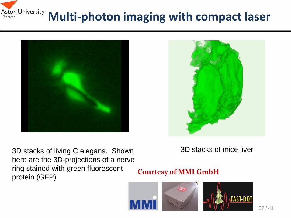
Courtesy of MMI GmbH
Multi-photon imaging with compact laser
3D stacks of living C.elegans. Shown
here are the 3D-projections of a nerve
ring stained with green fluorescent
protein (GFP)
3D stacks of mice liver
37 / 41

TPEF imaging from the MOPA system
38 / 41
In collaboration with ICFO Barcelona Y. Ding et al, Optics Express, v.20(13), p.14308, 2012
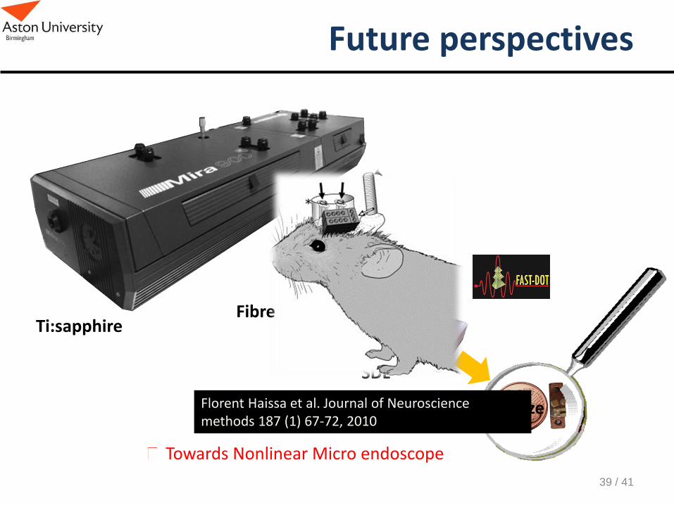
Future perspectives
Towards Nonlinear Micro endoscope
Ti:sapphire Fibre laser
SDL
Chip size Florent Haissa et al. Journal of Neuroscience methods 187 (1) 67-72, 2010
39 / 41

Conclusions
• The quantum-dot structures demonstrate big potential in ultrafast physics:
– Broad band tunability
– Generation of pico- and femtosecond pulses directly from edge-emitting laser diodes
– Generation of pico- and femtosecond pulses directly from surface-emitting laser diodes
– High-power
– Efficient SHG
• The high potential applicability of QD-based lasers in Biophotonics
40 / 41

Acknowledgments
Our collaborators
41 / 41
Optoelectronics and Biomedical Photonics Group 1. Dr. S. Sokolovski
2. Dr. N. Bazieva
3. Dr. A. Gorodetsky
4. Dr. K. Fedorova
5. Dr. Ilya Titkov
6. Dr. Yury Loika
7. Mr. Modestas Zulonas
8. Mr. Amit Yadav
9. New 6 MC Fellows