Embed Size (px)
Citation preview
1
e-sphyg TM 29002
Automatic Sphygmomanometer
AMERICAN DIAGNOSTIC CORPORATION
User’sManual

2
A SpecialThank You... Thank you for choosing an ADC® blood pressure instrument. We're proud of thecare and quality that goes into the manufacture of each and every item that bears ourname. Only the finest materials are used to assure you of a timeless instrument de-signed for optimum performance.
You'll quickly appreciate the results, for you now own one of the finest sphygmo-manometers that money can buy.
With proper care and maintenance, your ADC® blood pressure instrument is sureto provide you with many years of dependable service. Please read the following instruc-tions and general information which will prove helpful in allowing you to enjoy your ADC®
product.
Advantages of Digital Your new ADC® e-sphygTM 2 sphygmomanometer is intended to provide you with all of the functionality of a traditional sphygmomanometer, with none of the prob-lems associated with these devices. Using state-of-the-art technology, your e-sphygTM 2 sphygmomanometer will provide you with performance, versatility, andreliability exceeding the most popular aneroid and mercurial instruments.
Its dual mode design will permit the instrument to fully measure a patient’s bloodpressure and pulse automatically. In manual mode, it allows you to use the time provenauscultatory method to obtain blood pressure readings.
Thank you for your patronage. It is indeed our pleasure to serve you.
Sincerely, American Diagnostic Corp.
©2017 AMERICAN DIAGNOSTIC CORP.
3
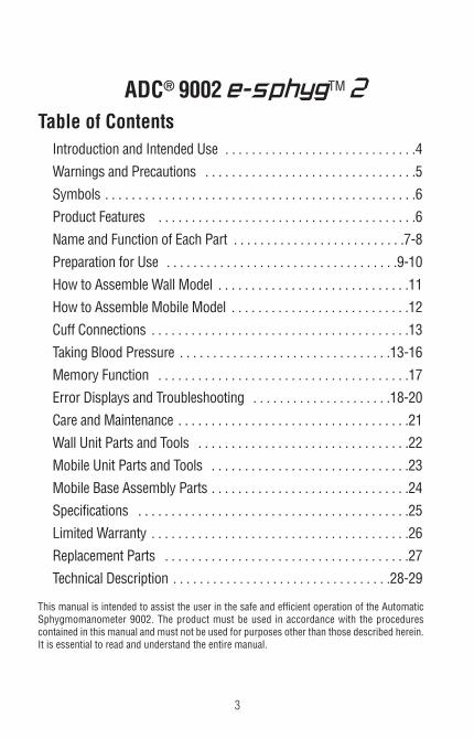
ADC® 9002e-sphygTM 2Table of Contents Introduction and Intended Use . . . . . . . . . . . . . . . . . . . . . . . . . . . . .4
Warnings and Precautions . . . . . . . . . . . . . . . . . . . . . . . . . . . . . . . .5
Symbols . . . . . . . . . . . . . . . . . . . . . . . . . . . . . . . . . . . . . . . . . . . . . . .6
Product Features . . . . . . . . . . . . . . . . . . . . . . . . . . . . . . . . . . . . . . .6
Name and Function of Each Part . . . . . . . . . . . . . . . . . . . . . . . . . .7-8
Preparation for Use . . . . . . . . . . . . . . . . . . . . . . . . . . . . . . . . . . .9-10
How to Assemble Wall Model . . . . . . . . . . . . . . . . . . . . . . . . . . . . .11
How to Assemble Mobile Model . . . . . . . . . . . . . . . . . . . . . . . . . . .12
Cuff Connections . . . . . . . . . . . . . . . . . . . . . . . . . . . . . . . . . . . . . . .13
Taking Blood Pressure . . . . . . . . . . . . . . . . . . . . . . . . . . . . . . . .13-16
Memory Function . . . . . . . . . . . . . . . . . . . . . . . . . . . . . . . . . . . . . .17
Error Displays and Troubleshooting . . . . . . . . . . . . . . . . . . . . .18-20
Care and Maintenance . . . . . . . . . . . . . . . . . . . . . . . . . . . . . . . . . . .21
Wall Unit Parts and Tools . . . . . . . . . . . . . . . . . . . . . . . . . . . . . . . .22
Mobile Unit Parts and Tools . . . . . . . . . . . . . . . . . . . . . . . . . . . . . .23
Mobile Base Assembly Parts . . . . . . . . . . . . . . . . . . . . . . . . . . . . . .24
Specifications . . . . . . . . . . . . . . . . . . . . . . . . . . . . . . . . . . . . . . . . .25
Limited Warranty . . . . . . . . . . . . . . . . . . . . . . . . . . . . . . . . . . . . . . .26
Replacement Parts . . . . . . . . . . . . . . . . . . . . . . . . . . . . . . . . . . . . .27
Technical Description . . . . . . . . . . . . . . . . . . . . . . . . . . . . . . . . .28-29 This manual is intended to assist the user in the safe and efficient operation of the AutomaticSphygmomanometer 9002. The product must be used in accordance with the procedurescontained in this manual and must not be used for purposes other than those described herein.It is essential to read and understand the entire manual.

4
Introduction and Intended Use
The 9002 digital ADC® e-sphygTM 2 sphygmomanometer is a digital sphygmo-manometer intended for measurement of systolic and diastolic blood pressureand pulse rate in adult patients, i.e., age 12 and above. This product is not de-signed for neonatal use. Inaccurate readings may result if it is used on a child'sarm.
Accuracy was evaluated during clinical studies in which results with the 9002digital ADC® e-sphygTM 2 sphygmomanometer were compared with simultane-ous auscultatory measurements obtained with a standard sphygmomanometer.In these studies, the onset of the fourth (or fifth) Korotkoff sound was taken asthe diastolic pressure for the purpose of determining overall efficacy. A copy ofthis study is available from ADC® on request. To ensure that accuracy is main-tained, compare readings obtained with the 9002 digital ADC® e-sphygTM 2sphygmomanometer with values measured by a trained observer using a manualsphygmomanometer at least every 6 months.
Blood pressure measurements determined with this device are equivalent to thoseobtained by a trained observer using the cuff stethoscope auscultatory method,within the limits prescribed by the American National Standard, Manual, electronic,or automated sphygmomanometers.
The 9002 digital ADC® e-sphygTM 2 sphygmomanometer has the ability to func-tion according to its specifications in the presence of common arrhythmia suchas atrial or ventricular premature beats or atrialfibrillation.

5
Warnings and Precautions
Warning - A warning statement in this manual identifies a condition or practice which, if not correctedor discontinued immediately could lead to patient injury, illness, or death.
Warning - If luer lock connectors are used in the construction of tubing, there is a possibility that theymight be inadvertently connected to intravascular fluid systems, allowing air to be pumped into a bloodvessel. Immediately consult a physician if this occurs.
Warning - Do not allow a blood pressure cuff to remain on patient for more than 10 minutes when in-flated above 10mmHg. This may cause patient distress, disturb blood circulation, and contribute to in-jury of peripheral nerves.
Warning - Safety and effectiveness with neonate cuff sizes 1 through 5 is not established.
Warning - For all blood pressure systems that can be wall mounted, ensure that the unit is securelymounted prior to use to avoid damage to the instrument and potential patient injury.
Warning - Do not use the 9002 in an explosive environment such as where flammable anesthetics exist or inside an oxygen chamber with strong electrostatic and electromagnetic fields e.g.,mobile phones.
Warning - Use of this instrument on patients under dialysis therapy or on anticoagulant, antiplatelets,or steroids could cause internal bleeding.
Warning - Do not use cuffs, AC adapters or batteries other than those included with this product orreplacement parts supplied by the manufacturer.
Warning - This system may fail to yield specified measurement accuracy if operated or stored in temperature or humidity conditions outside the limits stated in the specifications section of this manual.
Warning - When using with an infant or child cuff, extra care must be taken to prevent over-inflation.To prevent discomfort or injury to the patient, ensure preset pressure is not set above the desired level.
Warning -This product may contain a chemical known to the state of California to cause cancer, birthdefects, or other reproductive harm.
Caution - Federal law restricts this device to sale by or on the order of a physician or licensed health-care practitioner.
Caution - To avoid any possibility of accidental strangulation, keep this unit away from children anddo not drape tubing around your neck.
Note - To obtain the greatest accuracy from your blood pressure instrument, it is recommended thatthe instrument be used within a temperature range of 50°F (10°C) to 104°F (40°C), with a relative hu-midity range of 15-90% (non-condensing).
Note - All connectors and inflation system should remain connected to the device during storage toavoid dust entering through the connector port.

6
Symbols
Product FeaturesDUAL DISPLAY -COLUMN LCD and SEGMENT LCD (Simulated Mercury Column)The pressure can be read in the column LCD height and as digital value in thesegment LCD.
DUAL MEASUREMENT MODE -"AUTO" and "MANUAL" Modes of MeasurementDetermination of blood pressure can be made either automatically by the oscillometricmethod or manually by the auscultatory method using a stethoscope.
Cuff Sizes (Auto Mode)The Small Adult size cuff will accommodate arms of approximately 7.4 to 10.6 inches(19.0 to 27.0 centimeters). A Small Adult cuff should be used on patients 12 or olderonly (in auto mode).
The Adult size cuff will accommodate an upper arm circumference range of approxi-mately 9.0 to 15.7 inches (23.0 to 40.0 centimeters).
The Large Adult size cuff will accommodate that of approximately 13.3 to 19.6 inches(34.0 to 50.0 centimeters).
Symbol Definition
Read Operating Instructions
Not made with Natural Latex
Circumference Size
LATEX
Symbol Definition
Manufacturer’s Information
Temperature Limit
Humidity Limitation
Type BF Equipment
MODE DEFLATION RATE MEMORY AUTO Maintained at 4.0 to 4.9mmHg/sec Last measured result auto saved MANUEL Maintained at preset rates of: N/A 2.5, 4.5 or 6.5mmHg/sec
7
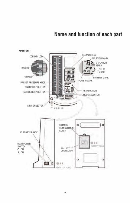
Name and function of each part
MAIN UNIT
COLUMN LCD
2mmHg
1mmHg
PRESET PRESSURE KNOB
START/STOP BUTTON
SET/MEMORY BUTTON
AIR CONNECTOR
AC INDICATOR
MODE SELECTOR
AIR PLUG
POWER MARKBATTERY MARK
PULSEMARK
DEFLATIONMARK
INFLATION MARKSEGMENT LCD
AC ADAPTER JACK
MAIN POWERSWITCHO :OFFI :ON
ADAPTER PLUG
BATTERYCONNECTOR
BATTERYCOMPARTMENTCOVER
BATTERY PLUG

8
Name and function of each part
SMALL ADULTArm circumferences of 7.4”-10.6”
(19.0-27.0cm)
ADULTArm circumferences of 9.0”-15.7”
(23.0-40.0cm)
LARGE ADULTArm circumferences of 13.3”-19.6”
(34.0-50.0cm)
AC ADAPTER RECHARGEABLENICKEL METAL HYBRID
(NiMH) BATTERY
INSTRUCTIONMANUAL
ADAPTER PLUG BATTERY PLUG
Cuff Sizes
AIRCONNECTOR(to main unit)
ADCUFFTM
BLADDER TUBE(Female Luer Connection)
COILED TUBING
LUER CONNECTOR(Male Luer to Female Blad-
der Tube)
Other parts included depending upon model selected.

9
Preparation for UseConnecting and Using the AC Adapter (All models)Connect AC ADAPTER PLUG to AC ADAPTER JACK
Plug AC ADAPTER in the power socket.AC INDICATOR is lit when AC ADAPTER is connected correctly.
Installing the RECHARGEABLE NiMH Battery (All models)NOTE: The battery enclosed in the product package is not charged, and needs to becharged for about 4 hours before use.
NOTE: Turn off the power and unplug AC ADAPTERbefore inserting the battery. Make sure "O " sideof MAIN POWER SWITCH is pressed down.
Remove BATTERY COMPARTMENT COVER byloosening and removing the screw. (Fig. 1)
Connect BATTERY PLUG to BATTERYCONNECTOR inside the battery compartmentand insert the battery. (Fig. 2)
Put back BATTERY COMPARTMENT COVER andclose it by inserting and tightening the screw.
Connect AC ADAPTER PLUG and plug ACADAPTER in the power socket to charge thebattery. The battery is charged regardless of whether the e-sphygTM 2 is powered on or off.
Orange light of AC INDICATOR indicates thatthe battery is being charged. (Fig. 3)The battery is fully charged after approximately 4 hours.
Unplug AC ADAPTER after the light turnsgreen as it indicates the battery is charged.
The color of the AC INDICATORmay switch to green and return toorange if the 9002 is operatedwhile charging battery, however itdoes not indicate a problem.
(Fig. 1)
(Fig. 2)
(Fig. 3)
ADAPTERPLUG
BATTERY PLUG
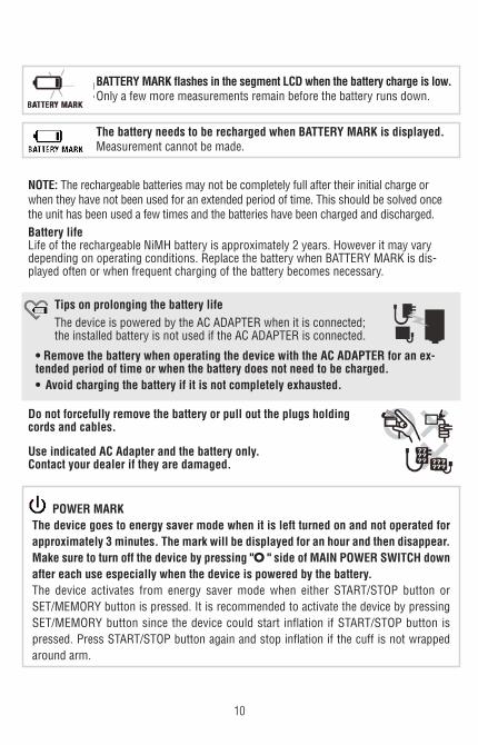
POWER MARKThe device goes to energy saver mode when it is left turned on and not operated forapproximately 3 minutes. The mark will be displayed for an hour and then disappear.Make sure to turn off the device by pressing "O " side of MAIN POWER SWITCH downafter each use especially when the device is powered by the battery.The device activates from energy saver mode when either START/STOP button orSET/MEMORY button is pressed. It is recommended to activate the device by pressingSET/MEMORY button since the device could start inflation if START/STOP button ispressed. Press START/STOP button again and stop inflation if the cuff is not wrappedaround arm.
Tips on prolonging the battery lifeThe device is powered by the AC ADAPTER when it is connected;the installed battery is not used if the AC ADAPTER is connected.
• Remove the battery when operating the device with the AC ADAPTER for an ex-tended period of time or when the battery does not need to be charged.• Avoid charging the battery if it is not completely exhausted.
10
BATTERY MARK flashes in the segment LCD when the battery charge is low.Only a few more measurements remain before the battery runs down.
The battery needs to be recharged when BATTERY MARK is displayed.Measurement cannot be made.
NOTE: The rechargeable batteries may not be completely full after their initial charge orwhen they have not been used for an extended period of time. This should be solved oncethe unit has been used a few times and the batteries have been charged and discharged.Battery lifeLife of the rechargeable NiMH battery is approximately 2 years. However it may varydepending on operating conditions. Replace the battery when BATTERY MARK is dis-played often or when frequent charging of the battery becomes necessary.
Do not forcefully remove the battery or pull out the plugs holdingcords and cables.
Use indicated AC Adapter and the battery only.Contact your dealer if they are damaged.

11
1. Securely attach wall bracket to flat surface using en-closed mollys and screws at desired height. (It is advised to use a level to ensure proper mounting). (Figure 1)
2. Attach manometer to wall bracket by lowering a top wallbracket, sliding male tab into female seat of the bracket.Secure the two together using the (6mm) allen bolt andwasher from below. Tighten securely with large (6mm)allen wrench (Figure 2).
3. Securely attach cuff basket to flat surface to left ofmanometer using enclosed mollys and screws at desiredheight. (It is advised to use a level to ensure even mounting)(Figures 3 - 4).
4. Attach 8 foot length coiled tubing to air inlet on face of e-sphygTM 2 (Figure 5).
Insert “male” luer connector (891M) on free end of coiled tubing to “female” luer connector (891F) on bladder tubing (Figure 6). Fold cuff and store in basket.
Figure 2
Figure 3
Figure 6
2e-sphyg
1308273
PRESET PRESSURE
MANUAL
AUTO280
260
220180
140
100
1020
40
60
80
100
120
140
160
180
200
220
240
260
280
300
30
50
70
90
110
130
150
170
190
210
230
250
270
290
POWERLOW BATTERY
AC
START/STOPSET/MEMORY
Figure 4
PRESET PRESSURE
MANUAL
AUTO280
260
220180
140
100
1020
40
60
80
30
50
70POWER
AC
START/STOPSET/MEMORY
Figure 1
Figure 5
How to Assemble Wall Model
12
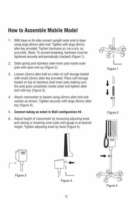
1. With base on its side connect upright outer pole to base using large (6mm) allen bolt. Tighten with large (6mm) allen key provided. Tighten hardware as securely aspossible. (Note: To prevent loosening, hardware must be tightened securely and periodically checked) (Figure 1).
2. Slide spring and stainless steel inner pole inside outer pole with open end up (Figure 2).
3. Loosen (3mm) allen bolt on collar of cuff storage basket with small (3mm) allen key provided. Place cuff storage basket on top of stainless steel inner pole making sure the pole goes completely inside collar and tighten allen bolt with key (Figure 3).
4. Attach manometer to basket using (6mm) allen bolt and washer as shown. Tighten securely with large (6mm) allen key (Figure 4).
5. Connect tubing as noted in Wall configuration #4.
6. Adjust height of manometer by loosening adjusting knob and raising or lowering inner pole until gauge is at desired height. Tighten adjusting knob by hand (Figure 5).
Figure 4
Figure 1
Figure 2
Figure 3
2e-sphyg
1308273
PRESET PRESSURE
MANUAL
AUTO280
260
220180
140
100
1020
40
60
80
100
120
140
160
180
200
220
240
260
280
300
30
50
70
90
110
130
150
170
190
210
230
250
270
290
POWERLOW BATTERY
AC
START/STOPSET/MEMORY
Figure 5
How to Assemble Mobile Model

13
PLUG / PORTCONNECTION
AIR CONNECTOR(Coiled Tubing)
Cuff Connections
1. Squeeze the middle of the plastic air connector on the end of coiled tubing between thumb and forefinger,and insert into the air connection port on the face of the e-sphyg 2TM. Make sure connector firmly “lock” snaps into the port (Figure 1).
2. Firmly insert male connector of coiled tubing into fe-male connector at end of the AdcuffTM bladder tub-ing. Be sure the connectors are tight (Figure 2).
MALECONNECTOR(Coiled Tubing)
FEMALE CONNECTOR(Bladder Tube)
Figure 2
Figure 1
Taking Blood Pressure (Auto Mode)Turn on the device by pressing "I" side of MAIN POWER SWITCH.
Move MODE SELECTOR downward and set the device to "AUTO".See page 15 for "MANUAL" measurement.
Set the initial inflation value with PRESET PRESSURE KNOB.
Select the pressure approximately 30 to 40 mmHg aboveexpected systolic pressure.Pressure can be set between 100 mmHg and 280 mmHg.Set the pressure at 180 mmHg if patient's systolic pressure isdifficult to predict.The cuff is re-pressurized to a higher value if the presetpressure is too low for blood pressure to be taken during cuffdeflation.

14
Apply the cuff to patient's arm.Choose the right size of cuff foryour patient. NOTE: Only these 3 cuffsmay be used in auto mode.
The lower edge of the cuff should be about 1” (2 to 3 cm)above the inner elbow and BLADDER TUBE should be over theinner part of the arm, positioning the ARTERY MARK of thecuff over the brachial artery.Press the surface of the cuff to make sure that the hook andloop adhesive fastens securely.The cuff should be wrapped loosely enough so that two fingers can be placed betweenthe cuff and patient's arm. If the cuff is wrapped tighter or looser than this,inaccurate blood pressure readings may result.If your patient is wearing a shirt that might restrict circulation in his/her upper arm orhe/she rolls his/her sleeve up over the upper arm, the blood flow will be restricted,preventing accurate measurement.
ARM CIRCUMFERENCE CUFF SIZE9.0 to 15.7 inches (23.0 to 40.0 cm) ADULT13.3 to 19.6 inches (34.0 to 50.0 cm) LARGE ADULT7.4 to 10.6 inches (19.0 to 27.0 cm) SMALL ADULT
Press START/STOP button.The cuff is inflated automatically after zero settings.Pressurization stops when pressure reaches the preset pressure value andpressure starts to descend.Heart mark flashes in the segment LCD synchronizing detected pulse.Deflation rate is displayed at the lower right corner of the segment LCD.
Press START/STOP button whenever the measurementshould be interrupted.
The device will stop during any course of measurementprocedure and rapidly exhaust air from the cuff.
Air is rapidly exhausted from the cuff asmeasurement completes.Blood pressure and pulse rate are displayed.
15
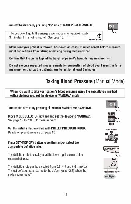
Taking Blood Pressure (Manual Mode)
When you want to take your patient's blood pressure using the auscultatory methodwith a stethoscope, set the device to "MANUAL" mode.
Turn on the device by pressing "I" side of MAIN POWER SWITCH.
Move MODE SELECTOR upward and set the device to "MANUAL".See page 13 for “AUTO” measurement.
Set the initial inflation value with PRESET PRESSURE KNOB.Details on preset pressure … page 13.
Press SET/MEMORY button to confirm and/or select theappropriate deflation rate.
The deflation rate is displayed at the lower right corner of thesegment display.
The deflation rate can be selected from 2.5, 4.5 and 6.5 mmHg/s.The set deflation rate returns to the default value (2.5) when thedevice is turned off.
Turn off the device by pressing "O" side of MAIN POWER SWITCH.
The device will go to the energy saver mode after approximately3 minutes if it is not turned off. See page 10.
Make sure your patient is relaxed, has taken at least 5 minutes of rest before measure-ment and refrains from talking or moving during measurement.
Confirm that the cuff is kept at the height of patient's heart during measurement.
Do not execute repeated measurements for congestion of blood could result in falsemeasurement. Allow the patient's arm to rest for at least 5 minutes.

16
If cuff inflation was not sufficient, press and hold downSTART/STOP button once deflation has started and the cuffis pressurized again. Pressurization will continue while thebutton is pressed. Pressure does not exceed 290 mmHg.
Press START/STOP button when blood pressure is taken and airis rapidly exhausted from the cuff.Air is also rapidly exhausted from the cuff when pressuredescends to 30 mmHg.
Turn off the device by pressing "O" side of MAIN POWER SWITCH.
The device will be in the energy saver mode after approximately3 minutes if it is not turned off. See page 10.
Make sure your patient is relaxed, has taken at least 5 minutes of rest beforemeasurement, and refrains from talking or moving during measurement.
Confirm that the cuff is kept at the height of patient's heart during measurement.
Do not execute repeated measurements for congestion of blood could resultin false measurement. Allow the patient's arm to rest for at least 5 minutes.
Apply the cuff and stethoscope to the patient's arm in the samemanner as the usual auscultatory method.
Press START/STOP button.The cuff is inflated automatically after zero settings.Pressurization stops when pressure reaches the preset pressure value andpressure starts to descend.Deflation rate is displayed at the lower right corner of the segment LCD.
NOTE: Press START/STOP button whenever the measurementshould be interrupted. The device will rapidly exhaust air from the cuff.

17
Memory FunctionMeasured result obtained in "AUTO" mode is automatically savedin the memory and can be recalled until next measurement is taken.The result is not saved when the measurement is performedin "MANUAL" mode.
To recall the result, turn on the device by pressing "I" side ofMAIN POWER SWITCH and set the device to "AUTO" withMODE SELECTOR.
Press SET/MEMORY button and the lastresult from "AUTO" measurement is displayed.
Turn off the device by pressing "O" side of MAIN POWER SWITCH.
The device will be in the energy saver mode after approximately3 minutes if it is not turned off. See page 10.

18
Error Displays and Troubleshooting ERROR SYMBOL/SYMPTOM CAUSE REMEDY
OVER-PRESSURIZATION:The cuff was inflated to the
maximum pressure because of movement of body, etc.
MEASUREMENT ERROR:Measurement could not bemade because of moving ortalking during measurement.
INFLATION ERROR: AIR PLUGis not correctly inserted.
Noise was detected.
DEFLATION ERROR:Movement or talking was de-tected during measurement.
Extreme changes in pressureoccurred during measurement.
CHECKING MODE: See page 21.
NO POWER: AC ADAPTER is not
correctly connected.
Battery is exhausted.
9002 was left turned on but has not been operated for over
an hour.
Make sure that the patient staysstill during measurement.
Make sure the patient remainsstill and quiet during measure-
ment.
Reinsert AIR PLUG and makesure that it is securely inserted.
Make sure that the patient staysstill and quiet during
measurement. Make sure the patient remains
still and quiet duringmeasurement.
Do not let patient move duringmeasurement.
Turn off the device once andthen turn it on again to take
measurement.
Reinsert AC ADAPTER andmake sure that it is securely
inserted.Charge the battery or use AC
ADAPTER.
Turn off the device or pressSTART/STOP button or
SET/MEMORY button to acti-vate the device from energy
saver mode.
Nothing is being dis-played when MAIN-POWER SWITCH is
pressed down in the ONposition.
19
Error Displays and Troubleshooting
ERROR SYMBOL/SYMPTOM CAUSE REMEDY
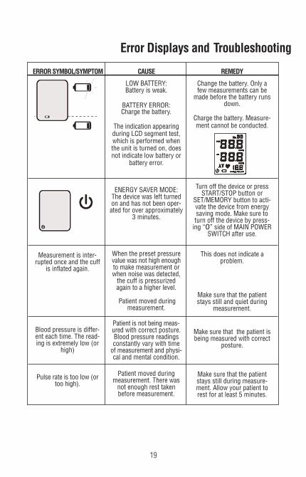
LOW BATTERY:Battery is weak.
BATTERY ERROR:Charge the battery.
The indication appearingduring LCD segment test,which is performed whenthe unit is turned on, doesnot indicate low battery or
battery error.
ENERGY SAVER MODE:The device was left turnedon and has not been oper-ated for over approximately
3 minutes.
When the preset pressurevalue was not high enoughto make measurement orwhen noise was detected,the cuff is pressurizedagain to a higher level.
Patient moved duringmeasurement.
Patient is not being meas-ured with correct posture.Blood pressure readingsconstantly vary with timeof measurement and physi-cal and mental condition.
Patient moved duringmeasurement. There wasnot enough rest taken before measurement.
Change the battery. Only afew measurements can be
made before the battery runsdown.
Charge the battery. Measure-ment cannot be conducted.
Turn off the device or pressSTART/STOP button or
SET/MEMORY button to acti-vate the device from energysaving mode. Make sure toturn off the device by press-ing “o” side of MAIN POWER
SWITCH after use.
This does not indicate a problem.
Make sure that the patientstays still and quiet during
measurement.
Make sure that the patient isbeing measured with correct
posture.
Make sure that the patientstays still during measure-ment. Allow your patient torest for at least 5 minutes.
Measurement is inter-rupted once and the cuff
is inflated again.
Blood pressure is differ-ent each time. The read-ing is extremely low (or
high)
Pulse rate is too low (ortoo high).
20
Error Displays and Troubleshooting
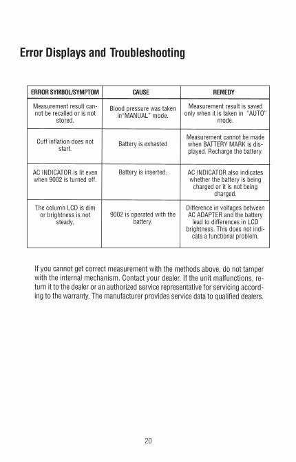
If you cannot get correct measurement with the methods above, do not tamperwith the internal mechanism. Contact your dealer. If the unit malfunctions, re-turn it to the dealer or an authorized service representative for servicing accord-ing to the warranty. The manufacturer provides service data to qualified dealers.
ERROR SYMBOL/SYMPTOM CAUSE REMEDY
Measurement result can-not be recalled or is not
stored. Cuff inflation does not
start.
AC INDICATOR is lit evenwhen 9002 is turned off.
The column LCD is dimor brightness is not
steady.
Blood pressure was takenin“MANUAL” mode.
Battery is exhasted
Battery is inserted.
9002 is operated with thebattery.
Measurement result is savedonly when it is taken in “AUTO”
mode.
Measurement cannot be madewhen BATTERY MARK is dis-played. Recharge the battery.
AC INDICATOR also indicateswhether the battery is beingcharged or it is not being
charged.
Difference in voltages betweenAC ADAPTER and the batterylead to differences in LCD
brightness. This does not indi-cate a functional problem.
21
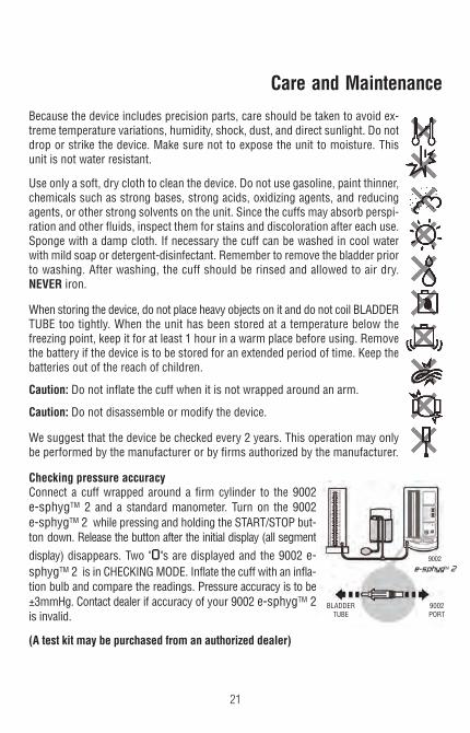
Because the device includes precision parts, care should be taken to avoid ex-treme temperature variations, humidity, shock, dust, and direct sunlight. Do notdrop or strike the device. Make sure not to expose the unit to moisture. Thisunit is not water resistant.
Use only a soft, dry cloth to clean the device. Do not use gasoline, paint thinner,chemicals such as strong bases, strong acids, oxidizing agents, and reducingagents, or other strong solvents on the unit. Since the cuffs may absorb perspi-ration and other fluids, inspect them for stains and discoloration after each use.Sponge with a damp cloth. If necessary the cuff can be washed in cool waterwith mild soap or detergent-disinfectant. Remember to remove the bladder priorto washing. After washing, the cuff should be rinsed and allowed to air dry.NEVER iron.
When storing the device, do not place heavy objects on it and do not coil BLADDERTUBE too tightly. When the unit has been stored at a temperature below thefreezing point, keep it for at least 1 hour in a warm place before using. Removethe battery if the device is to be stored for an extended period of time. Keep thebatteries out of the reach of children.
Caution: Do not inflate the cuff when it is not wrapped around an arm.
Caution: Do not disassemble or modify the device.
We suggest that the device be checked every 2 years. This operation may onlybe performed by the manufacturer or by firms authorized by the manufacturer.
Checking pressure accuracyConnect a cuff wrapped around a firm cylinder to the 9002e-sphygTM 2 and a standard manometer. Turn on the 9002e-sphygTM 2 while pressing and holding the START/STOP but-ton down. Release the button after the initial display (all segmentdisplay) disappears. Two "0"s are displayed and the 9002 e-sphygTM 2 is in CHECKING MODE. Inflate the cuff with an infla-tion bulb and compare the readings. Pressure accuracy is to be±3mmHg. Contact dealer if accuracy of your 9002 e-sphygTM 2is invalid.
(A test kit may be purchased from an authorized dealer)
9002e-sphygTM 2
9002PORT
BLADDERTUBE
Care and Maintenance

22
9002W - Wall Unit Parts & Tools
ADC Item Item no.
1. e-sphygTM 2 90022. 6mm Allen Wrench 752M-116
3. Wall Bracket 952-103
4. Wall Basket with (3) screws / (3) mollys 952-025
5. Coiled tubing 885N
6. Mounting Bolt/Washer (1) 972-101
7. Connector 9002-2
8. Connector, Male 891M
9. Connector, Female 891F
10. AdcuffTM & Bladder, Adult 845-11AN-1F
11. (2) Screws (for wall bracket) 952-104
12. (2) Mollys (for wall bracket) 952-105
752M-116
2e-sphyg
1308273
PRESET PRESSURE
MANUAL
AUTO280
260
220180
140
100
1020
40
60
80
100
120
140
160
180
200
220
240
260
280
300
30
50
70
90
110
130
150
170
190
210
230
250
270
290
POWERLOW BATTERY
AC
START/STOPSET/MEMORY
9002
952-103
952-025
885N
SELECT
LARGER CUFF
ADCUFF
ADULT SIZE
RANGE / MAX
ARTERY
845-11AN-1F9002-2
891M
891F
1
2
3
4
5
6
972-101
7
8
9
10
12
952-105
11
952-104

23
752M-116
752M-117
2e-sphyg
1308273
PRESET PRESSURE
MANUAL
AUTO280
260
220180
140
100
1020
40
60
80
100
120
140
160
180
200
220
240
260
280
300
30
50
70
90
110
130
150
170
190
210
230
250
270
290
POWERLOW BATTERY
AC
START/STOPSET/MEMORY
9002
752M-02
9002M - Mobile Unit Parts & Tools
885N
SELECT
LARGER CUFF
ADCUFF
ADULT SIZE
RANGE / MAX
ARTERY
845-11AN-1F
9002-2
891M 891F
1
2
3
4
5
6
7 972-101
8 9
10
ADC Item Item no.
1. e-sphygTM 2 90022. 6mm Allen Wrench 752M-116
3. 3mm Allen Wrench 752M-117
4. Mounting Bolt/Washer (2) 972-101
5. Mobile Stand 752M-02
6. Coiled tubing 885N
7. Connector 9002-2
8. Connector, Male 891M
9. Connector, Female 891F
10. AdcuffTM & Bladder, Adult 845-11AN-1F
24
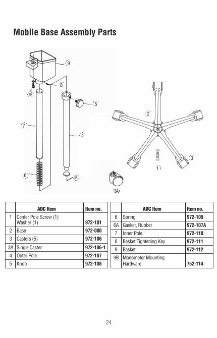
ADC Item Item no.
1 Center Pole Screw (1) Washer (1) 972-101 2 Base 972-080
3 Casters (5) 972-106
3A Single Caster 972-106-1
4 Outer Pole 972-107
5 Knob 972-108
Mobile Base Assembly Parts
ADC Item Item no.
6 Spring 972-109
6A Gasket, Rubber 972-107A
7 Inner Pole 972-110
8 Basket Tightening Key 972-111
9 Basket 972-112
9B Manometer Mounting Hardware 752-114
9B
5
6
7
8
9
1
2
3
3A
4
6A

25
Specifications Operating Principle: Oscillometric method* Indicator: 300 digits column LCD and 10 digits segment LCD Pressure Indicating Range: 0 to 300 mmHg (cuff pressure) Measuring Range: 50 to 250 mmHg (systolic) 40 to 180 mmHg (diastolic) 40 to 160 bpm (pulse rate) Accuracy: ±3 mmHg (cuff pressure) ±5% of reading (pulse rate) Inflation : Automatic inflation Deflation: Electric control valve Exhaust: Automatic exhaust valve Power Supply: Power Supply: 7.0 VDC AC Adapter (Model UM318-0725 or
4.8 VDC Rechargeable Ni-MH Battery Adapter I/P: AC100-240V Power Consumption : 14W (max.) Memory: single measurement result* Operating Environment: +50°F to+104°F, 15 to 85% relative humidity Storage Environment: -4°F to+140°F, 15 to 85% relative humidity
Coverage Arm Circumference
Adult Size Cuff: 9.0 to 15.7 inches (23.0 to 40.0 cm) Large Adult Size Cuff: 13.3 to 19.6 inches (34.0 to 50.0 cm) Small Adult Size Cuff: 7.4 to 10.6 inches (19.0 to 27.0 cm)
Main Unit Weight: Approx. 2.2 lb. [1000 g], without AC adapter or battery Size: 5.4 x 10.6 x 3.8 in [136 x 266 x 96 mm] (W x D x H)
Specifications are subject to change without notice due to improvements in performance.* marks only apply to "AUTO" measurement.

26
American Diagnostic Corporation (ADC®) warrants its products against defects in materi-als and workmanship under normal use and service as follows:
1. Warranty service extends to the original retail purchaser only and commences with the date of delivery.
2. The entire sphygmomanometer is warranted for two years.
3. Cuff, bladder and coiled tubing are warranted for three years.
4. The manometer is warranted to remain accurate to ±3mmHg over its full range when compared to a reference standard for life.
What is Covered: Repair, or replacement of parts, and labor.
What is not covered: Transportation charges to and from ADC®. Damages caused by abuse,misuse, accident, or negligence. Incidental, special, or consequential damages. Some statesdo not allow the exclusion or limitation of incidental,special, or consequential damages, so this limitation may not apply to you.
To Obtain Warranty Service: Send item(s) postage paid to ADC®, Attn: Service Dept., 55 Com-merce Dr., Hauppauge, NY 11788. Please include your name and address, daytime phoneno., proof of purchase, a brief note explaining the problem, and $2.00 to cover the cost ofreturn shipping and handling.
Implied Warranty: Any implied warranty shall be limited in duration to the terms of this war-ranty and in no case beyond the original selling price (except whereprohibited by law). This warranty gives you specific legal rights and you may have otherrights which vary from state to state.
To Register Your Product, visit us at www.adctoday.com/register
Limited Warranty

27
FOR QUESTIONS, COMMENTS,OR SUGGESTIONS
CALL TOLL FREE: 1-800-ADC-2670OR VISIT
WWW.ADCTODAY.COM/FEEDBACK
©2017 ADC®. All rights reserved. No one is permitted to reproduce or duplicate in any form, this manualor any part thereof without the expressed written permission of ADC®. ADC® assumes no responsibilityfor any injury to anyone, or for any illegal or improper use of the product that may result from failureto use the product in accordance with the instructions, cautions, warnings, or statement of intendeduse published in this manual. The 9002 e-sphyg 2TM and AdcuffTM are trademarks of ADC®.
Replacement Parts
Many ADC instruction manuals are available on our website in other languages atwww.adctoday.com/care
Component
Coiled Tubing 4’
Coiled Tubing 8’
Cuff & Bladder - Sm. Adult
Cuff & Bladder - Adult
Cuff & Bladder - Lg. Adult
Female Luer Connector
Male Luer Connector
Plastic Connector
AC Adapter
Rechargeable Battery Pack
Part No. Latex-free
886N
885N
845-10SARB-1F
845-11AN-1F
845-12XBD-1F
891F
891M
9002-2
9002-3
9002-5
Model Use
Desk
Mobile, Wall
All Models
All Models
All Models
All Models
All Models
All Models
All Models
All Models
28
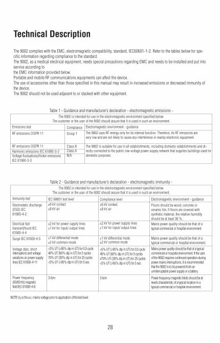
The 9002 complies with the EMC, electromagnetic compatibility, standard, IEC60601-1-2. Refer to the tables below for spe-cific information regarding compliance to the standard.The 9002, as a medical electrical equipment, needs special precautions regarding EMC and needs to be installed and put intoservice according tothe EMC information provided below.Portable and mobile RF communications equipments can affect the device.The use of accessories other than those specified in this manual may result in increased emissions or decreased immunity ofthe device.The 9002 should not be used adjacent to or stacked with other equipment.
The 9002 is intended for use in the electromagnetic environment specified below.The customer or the user of the 9002 should assure that it is used in such an environment.
Table 1 - Guidance and manufacturer’s declaration - electromagnetic emissions -
The 9002 is intended for use in the electromagnetic environment specified below.The customer or the user of the 9002 should assure that it is used in such an environment.
Table 2 - Guidance and manufacturer’s declaration - electromagnetic immunity -
Technical Description
Emissions test
RF emissions CISPR 11
RF emissions CISPR 11 Harmonic emissions IEC 61000-3-2 Voltage fluctuations/flicker emissionsIEC 61000-3-3
Compliance
Group 1
Class B Class A N/A
Electromagnetic environment - guidance
The 9002 uses RF energy only for its internal function. Therefore, its RF emissions arevery low and are not likely to cause any interference in nearby electronic equipment.
The 9002 is suitable for use in all establishments, including domestic establishments and di-rectly connected to the public low-voltage power supply network that supplies buildings used fordomestic purposes.
Immunity test
Electrostatic discharge (ESD) IEC 61000-4-2
Electrical fast transient/burst IEC 61000-4-4
Surge IEC 61000-4-5
Voltage dips, short interruptions and voltage variations on power supply lines IEC 61000-4-11
Power frequency (50/60 Hz) magneticfield IEC 61000-4-8
IEC 60601 test level ±6 kV contact ±8 kV air
±2 kV for power supply lines±1 kV for input/ output lines
±1 kV differential mode ±2 kV common mode
<5% UT (>95% dip in UT) for 0,5 cycle40% UT (60% dip in UT) for 5 cycles70% UT (30% dip in UT) for 25 cycles<5% UT (>95% dip in UT) for 5 sec
3 A/m
Compliance level ±6 kV contact ±8 kV air ±2 kV for power supply lines ±1 kV for input/ output lines
±1 kV differential mode ±2 kV common mode
<5% UT (>95% dip in UT) for 0,5 cycle 40% UT (60% dip in UT) for 5 cycles v70% UT (30% dip in UT) for 25 cycles <5% UT (>95% dip in UT) for 5 sec
3 A/m
Electromagnetic environment - guidance
Floors should be wood, concrete orceramic tile. If floors are covered withsynthetic material, the relative humidityshould be at least 30 %.Mains power quality should be that of atypical commercial or hospital environment.
Mains power quality should be that of a typical commercial or hospital environment.
Mains power quality should be that of a typicalcommercial or hospital environment. If the userof the 9002 requires continued operation duringpower mains interruptions, it is recommendedthat the 9002 is to be powered from anuninterruptable power supply or a battery.
Power frequency magnetic fields should be atlevels characteristic of a typical location in atypical commercial or hospital environment.
NOTE UT is the a.c. mains voltage prior to application of the test level.
29
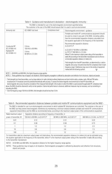
The 9002 is intended for use in the electromagnetic environment specified below.The customer or the user of the 9002 should assure that it is used in such an environment.
Table 4 - Guidance and manufacturer’s declaration - electromagnetic immunity -
The 9002 is intended for use in an electromagnetic environment in which radiated RF disturbances are controlled. The customer or the user ofthe 9002 can help prevent electromagnetic interference by maintaining a minimum distance between portable and mobile RF communicationsequipment (transmitters) and the 9002 as recommended below, according to the maximum output power of the communications equipment.
Rated maximum output Separation distance according to frequency of transmitter, m
power of transmitter, W 150 kHz to 80 MHz, d=[3.5/V1]�P 80 MHz to 800 MHz, d=[3.5/E1]�P 800 MHz to 2.5 GHz, d=[7/E1]�P
0.01 0.12 0.12 0.23
0.1 0.38 O.38 0.73
1 1.2 1.2 2.3
10 3.8 3.8 7.3
100 12 12 23
For transmitters rated at a maximum output power not listed above, the recommended separation distance d in meters (m) can be estimated usingthe equation applicable to the frequency of the transmitter, where P is the maximum output power rating of the transmitter in watts (W) accordingto the transmitter manufacturer.
NOTE1: At 80 MHz and 800 MHz, the separation distance for the higher frequency range applies.
NOTE2: These guidelines may not apply in all situations. Electromagnetic propagation is affected by absorption and reflection from structures, objects and people.
Table 6 - Recommended separation distances between portable and mobile RF communications equipment and the 9002 -
NOTE 1: At 80 MHz and 800 MHz, the higher frequency range applies.NOTE 2: These guidelines may not apply in all situations. Electromagnetic propagation is affected by absorption and reflection from structures, objects and people.
a Field strength from fixed transmitters, such as base stations for radio (cellular/cordless) telephones and land mobile radios, amateur radio, AM and FM radios broadcast and TV broadcast cannot be predicted theoretically with accuracy. To assess the electromagnetic environment due to fixed RF transmitters, an electromagnetic site survey should be considered. If the measured field strength in the location in which the 9002 is used exceeds the applicable RF compliance level above, the 9002 should be observed to verify normal operation. If abnormal performance is observed, additional measures may be necessary, such as reorienting or relocating the 9002.b Over the frequency range 150 kHz to 80 MHz, field strengths should be less than 3 V/m.
Immunity test
Conducted RF IEC 61000-4-6 Radiated RF IEC 61000-4-3
IEC 60601 test level
3 Vrms 150 kHz to 80 MHz
3 Vrms 80 MHz to 2,5 GHz
Compliance level
3 Vrms
3 Vrms
Electromagnetic environment - guidance
Portable and mobile RF communications equipment shouldbe used no closer to any part of the 9002, including cables,than the recommended separation distance calculated fromthe equation applicable to the frequency of the transmitter. Recommended separation distanced=[3,5/V1]�P
d=[3,5/E1]�P 80 MHz to 800 MHz d=[7/E1]�P 800 MHz to 2,5 GHz Where P is the maximum output power rating of the transmitter inwatts (W) according to the transmitter manufacturer and d is the rec-ommended separation distance in meters (m).
Field strengths from fixed RF transmitters, as determined by a electro-magnetic site survey,a should be less than the compliance level in eachfrequency range.b Interference may occur in the vicinity of equipmentmarked with the following symbol:

30
ADC 55 Commerce Drive Hauppauge, NY 11788 U.S.A.
Inspected, Assembled and Packaged in the U.S.A.Made in Japan
tel: 631-273-9600, 1-800-232-2670fax: 631-273-9659
www.adctoday.comemail: [email protected]
IB p/n 93-9002-00 rev 11 Printed in JapanA114487-1_7