Embed Size (px)
Citation preview

International Journal of Electronic and Electrical Engineering. ISSN 0974-2174 Volume 5, Number 1 (2012), pp. 39-57 © International Research Publication House http://www.irphouse.com
E-Shape Microstrip Patch Antenna for Pervasive Wireless Communication at 14GHz (Ku Band)
1Dr. Anubhuti Khare, 2Rajesh Nema, 3Puran Gour and 4Rajeev Kumar Thakur
1UIT, RGPV, Bhopal, India
E-mail: [email protected] 2,3,&4NIIST, Bhopal, India
E-mail: [email protected], [email protected] [email protected]
Abstract
The area of micro strip antennas has seen some inventive work in recent years and is currently one of the most dynamic fields of antenna theory. An overview of work done in the area of micro strip antennas is presented and several recent developments in the field are highlighted. In addition, new antenna configurations that improve electrical performance and manufacturability are described. This designing is very easy and chip in microstrip antenna designing. We analyzed micro strip antenna in IE3D by finite moment of method. The proposed antenna design on a 31 mil RT DUROID 5880 substrate from Rogers-Corp with dielectric constant of 2.2 and loss tangent of .004. At 14GHz the verify and tested result on IE3D SIMULATOR are Return loss = -10.35dB, VSWR=1.872, Directivity=6dbi, Z=32.94Ω Characteristic impedance, All results shown in simulation results. The results shown in Table 1, Table2, Keywords: Micro strip antenna, IE3D SIMULATOR, Dielectric, Patch width, Patch Length, Characteristic Impedance, Losses, strip width, strip length
Introduction to Microstrip Antenna A A Deshmukh and G Kumar [9] proposed compact L Shape patch broadband Microstrip antenna experimentally increase bandwidth up to 13.7%. Z M Chen [14] further increase bandwidth of this antenna up to 23.7% - 24.4%. J George [3] proposed optimal angle between feed line and patch for enhancing bandwidth. K F

40
Lee[14] proposed U Shaincrease bandwidth up tpermittivity in proposed significant increasing in bI Shafai [2] enhances gainmultiple conductor layeruniplanar photonic bandKhodier[11] New wideban W. S. Yun, Wideband Major issue for micro-antenna provide optimum10.35dB.The results of pverified in IE3D Simulmathematical analysis of m
Effective Parameters The electric field radiateddifferent dielectrics: air anthe field at the boundary, have an effective patch leperforming micro strip ancalculated by this formula
Dr. Anubh
ape slot shorting post small size Microstripto 42%. Z M chen Tsai K F Lee [14] design for enhancing Bandwidth. R Gargandwidth by increasing height of dielectric m
n and bandwidth by novel technique form rinr separated by laminating dielectric. S C d gap structure for enhancing band widthnd stacked microstrip antennas for enhancing microstrip antennas for PCS/IMT-2000 servi
-strip antenna is narrow Bandwidth. Our propm results at 14GHz VSWR is 1.872 and rproposed E-Shaped Multiband micro-strip lator .All results shown in simulation rmicro strip given below
Figure 1
d from a micro strip antenna meets a boundarnd the substrate material. Because of the sligthe patch can appear longer in an electrical
ength. There is also an effective relative perntenna analysis. The effective relative permused widely in
huti Khare et al
p Antenna and [13] used low
g P Bharti [10] material. Latif S ng by depositing
Gao [8] used h and gain. M
band width. ices. posed E shaped return loss is -
patch antenna result..We find
ry between two ght distortion of sense. Thus we rmittivity when
mittivity can be

E-Shape Microstrip Patch Antenna 41
E-plane pattern
0
kwsin coskV w 2E sin kw2 r cos
2
jkrФ e
θθ
π θ
−
⎡ ⎤⎛ ⎞⎛ ⎞⎜ ⎟⎢ ⎥⎜ ⎟⎝ ⎠⎢ ⎥⎜ ⎟=
⎢ ⎥⎜ ⎟⎜ ⎟⎢ ⎥⎝ ⎠⎣ ⎦
H-plane pattern Hө = EФ /η Characteristic impedance of microstrip line feed for w/h ≤ 1
reff
060 8 wZ ln
w 4h
hε⎡ ⎤= +⎢ ⎥⎣ ⎦
for w/h ≥1
0
reff
1 20 Z w w 1.393 .667 ln 1.44h h
π
ε=
⎡ ⎤⎛ ⎞+ + +⎜ ⎟⎢ ⎥⎝ ⎠⎣ ⎦
Beam widths E-plane
( )
127.03 02cos 2 2 24 3Le h
λθπ
−≅+
E
H-plane
1 12cos
2H
kwθ −≅
+

42 Dr. Anubhuti Khare et al
Transmission line method is the easiest method as compared to the rest of the methods. This method represents the rectangular micro strip antenna as an array of two radiating slots, separated by a low impedance transmission line of certain length.
The following effects are taken into account for this model: Fringing Effects: As the dimensions of the patch are finite along the length and the width, the fields at the edges of the patch undergo fringing i.e. the field exists outside the dielectric thus causing a change in the effective dielectric constant. It is a function of the dimensions of the patch and the height of the substrate.
Figure 2 The above Figure 3 shows a patch antenna from the Transmission Line Model perspective. We can observe the fringing at the edges increasing the effective length.

E-Shape Microstrip Patch Antenna 43
1/2
( r 1) ( r 1) h 1 10
2 2 wreff
ε εε−− + ⎛ ⎞= + +⎜ ⎟
⎝ ⎠
r
c 2w 2 1rf ε
=+
Proposed Antenna at 14GHz
The Proposed antenna has: Proposed Patch length = 4L Proposed Patch Width = 4W Strip Path Length= 1500miles Strip Path Width= 70miles Cut width =300miles Cut depth = 300 miles
r
c 2w 2 1rf ε
=+
r
c 2w 2 1rf ε
=+

44 Dr. Anubhuti Khare et al
Simulated Microstrip Patch Antenna in IE3D VSWR vs Frequency (IN GHz)
For proposed design the value of VSWR is effective between 14GHz to 20GHz, for this value return loss is minimum. At 14GHz return loss is -10.35dB and VSWR is 1.872, At 7GHz VSWR is 3.581, At 12GHz VSWR is 4.712, at 15GHz VSWR is 5.197, at 17GHz VSWR is 7.404, at 18GHz VSWR is 3.931,at 20GHz VSWR is 5.683
E-Shape Microstrip Patch Antenna 45
Directivity vs Frequency (IN GHz)
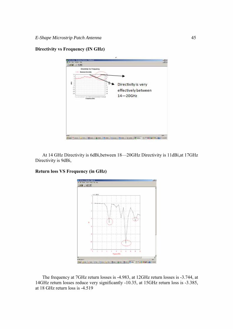
At 14 GHz Directivity is 6dBi,between 18—20GHz Directivity is 11dBi,at 17GHz Directivity is 9dBi, Return loss VS Frequency (in GHz)
The frequency at 7GHz return losses is -4.983, at 12GHz return losses is -3.744, at 14GHz return losses reduce very significantly -10.35, at 15GHz return loss is -3.385, at 18 GHz return loss is -4.519

46 Dr. Anubhuti Khare et al
S Parameter (magnitude in db and phase) VS Frequency in GHz
Magnitude and phase of Z Parameters VS Frequency in GHz

E-Shape Microstrip Patch Antenna 47
SIMTH CHART FOR DIFFERENT MEASURMENT
(Antenna Efficiency and Radiating Efficiency) VS (Frequency in GHz)

48 Dr. Anubhuti Khare et al
Radiation Pattern Study of different Azimuth pattern and Elevation pattern in IE3D .Analyzed radiation characteristic of antenna at 10 GHz shown in figure Elevation Pattern
Elevation Pattern of E maximum,
E Theta at phi= 0deg
a
Elevation Pattern of E Total at phi =90(deg)

E-Shape Microstrip Patch Antenna 49
Elevation Pattern of E Total, E Right, E left, E theta, E Phi at phi=90 (deg)
Elevation Pattern of E Total at phi =170(deg)
Azimuth Pattern
Azimuth Pattern at E theta, theta=0(deg)

50 Dr. Anubhuti Khare et al
Azimuth Pattern of E Total at theta=90(deg)
Azimuth Pattern of E Total at theta=45(deg)
Azimuth Pattern of E Total at theta=55(deg)

E-Shape Microstrip Patch Antenna 51
Azimuth Pattern of E Total, E Right, E left, E theta, E Phi at theta=90(deg)
Axial Ratio Pattern For Azimuth Pattern
Axial Pattern at theta=90(deg)
Axial Pattern at theta=45(deg)

52 Dr. Anubhuti Khare et al
Axial Pattern at theta=0(deg)
For Elevation Pattern
Axial Pattern at Phi =0(deg)
Axial Pattern at Phi =50(deg)

E-Shape Microstrip Patch Antenna 53
Axial Pattern at Phi =90(deg)
Axial Pattern at Phi =170(deg), Phi =90(deg),
Axial ratio vs. Frequency
54 Dr. Anubhuti Khare et al
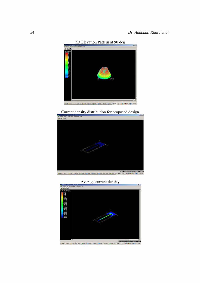
3D Elevation Pattern at 90 deg
Current density distribution for proposed design
Average current density

E-Shape Microstrip Patch Antenna 55
Table 1: dB [S (i j)] in dB and Ang[S (i j)] in Deg
Freq[Ghz] dB[S(1,1)] 1 ‐2.912e‐0.02
2 ‐5.98e‐0.02 3 ‐6.412e‐0.02
4 ‐0.1106 5 ‐0.1389 6 ‐0.9716 7 ‐4.983 8 ‐0.3035 9 ‐0.3481 10 ‐1.037 11 ‐0.4362 12 ‐3.744 13 ‐1.181 14 ‐10.35 15 ‐3.385 16 ‐1.22 17 ‐2.361 18 ‐4.519 19 ‐2.868 20 ‐3.089
Table 2: Frequency (GHz) vs. VSWR (MEASUREMENT BY IE3D SIMULATOR)
Frequency[GHz] VSWR
1 596.5 2 290.5 3 270.9 4 157.1 5 125.1 6 17.9 7 3.581 8 57.24 9 49.91 10 16.77 11 39.83 12 4.712 13 14.73 14 1.872

56 Dr. Anubhuti Khare et al
15 5.197 16 14.26 17 7.404 18 3.931 19 6.111 20 5.683
Conclusion Microstrip antennas have become a rapidly growing area of research. Their potential applications are limitless, because of their light weight, compact size, and ease of manufacturing. One limitation is their inherently narrow bandwidth. However, recent studies and experiments have found ways of overcoming this obstacle. A variety of approaches have been taken, including modification of the patch shape, experimentation with substrate parameters, Most notably mobile communication systems where many frequency ranges could be accommodated by a single antenna. We here design simple and low costlier patch antenna for pervasive wireless communication. The proposed frequency range 14GHz (Ku Band) and Analysis Radiation Characteristics of micro strip Antenna by IE3D Simulator. The transmission line model seems to be the most instructive in demonstrating the bandwidth effects of the changing the various parameters. The proposed antenna design on a 31mil RT DUROID 5880 substrate from Rogers-Corp with dielectric constant of 2.2 and loss tangent of .004. The proposed antenna has four times patch length, four times patch width and more feed line length. The results of proposed designing are effective between 14GHz-20GHz. proposed antenna simulated in IE3D Simulator. The optimum results of proposed antenna verify and tested in IE3D SIMULATOR. The simulated results of IE3D at 14GHz is Return loss = -10.35db, VSWR = 1.872, Directivity =8dbi. The proposed E-Shaped multiband microstrip antenna effective work on 7GHz, 12GHz, at 14GHz (Ku Band) the proposed antenna work very effectively for pervasive wireless communication. References
[1] Design considerations for rectangular rmicrostrip patch antenna on electromagnetic crystal substrate at terahertz frequency Infrared Physics & Technology, Volume 53, Issue 1, January 2010, Pages 17-22 G. Singh
[2] Latif, S.I. Shafai, L. Shafai, C. Dept. of Electr. & Comput. Eng., Univ. of Manitoba, Winnipeg, MB “Ohmic loss reduction and gain enhancement of microstrip antennas using laminated conductors “Antenna Technology and Applied Electromagnetics and the Canadian Radio Science Meeting, 2009. ANTEM/URSI2009. 13th International Symposium on Toronto,
[3] 2009 WRI International Conference on Communications and Mobile Computing Improved Microstrip Fractal Patch Antenna Using Uni-planar

E-Shape Microstrip Patch Antenna 57
Compact Photonic Bandgap Structure (UC-PBG) January 06-January 08 Gao Wei Deng Hui
[4] Progress in Electromagnetics Research Symposium Proceedings, Moscow, Russia, August 1821, 2009 1087 Annular Ring Micro strip Patch Antenna on a Double Dielectric Anisotropic Substrate C. F. L. Vasconcelos1, S. G. Silva1, M. R. M. L.Albuquerque1, J. R. S. Oliveira2, and A. G. d'Assun»c~ao1
[5] Abbaspour,M. and H. R. Hassani, Wideband star-sharped microstrip patch antenna,"Progress In Electromagnetic Research Letters, Vol. 1, 6168, 2008.
[6] Sabri, H. and Z. Atlasbaf, \Two novel compact triple-band micro strip annular-ring slot antenna for PCS-1900 and WLAN applications," Progress In Electromagnetics Research Letters, Vol. 5, 8798, 2008
[7] A.Shackelford, K. F. Lee, D. Chatterjee, Y. X. Guo, K. M. Luk, and R. Chair,“Small size wide bandwidth microstrip patch antennas,” in IEEE Antennas and Propagation International Symposium, vol. 1, (Boston, Massachusetts), pp. 86–89,IEEE, July 2001.
[8] S. C. Gao, L. W. Li, M. S. Leong, and T. S. Yeo, “Design and analysis of a novel wideband microstrip antenna,” in IEEE Antennas and Propagation International Symposium,vol. 1, (Boston, Massachusetts), pp. 90–93, IEEE, July 2001.
[9] A.A.Deshmukh and G. Kumar, “Compact broadband gap-coupled shorted L-shaped microstrip antennas,” in IEEE Antennas and Propagation International Symposium, vol 1, (Baltimore, Maryland), pp. 106–109, IEEE, July 2001.
[10] R. Garg, P. Bhartia, I. Bahl, and A. Ittipiboon, Microstrip Antenna Design Handbook.London: Artech House, 2001.
[11] M. Khodier and C. Christodoulou, “A technique to further increase the bandwidth Of stacked microstrip antennas,” in IEEE Antennas and Propagation International Symposium, vol. 3, (Salt Lake City, Utah), pp. 1394–1397, IEEE, July 2000.
[12] K. Wong and W. Hsu, “A broadband patch antenna with wide slits,” in IEEE Antennas and Propagation International Symposium, vol. 3, (Salt Lake City, Utah),pp. 1414– 1417, IEEE, July 2000.
[13] K. F. Lee, K. M. Luk, K. F. Tong, Y. L. Yung, and T. Huynh, “Experimental study of the rectangular patch with a U-shaped slot,” in IEEE Antennas and Propagation International Symposium, vol. 1, (Baltimore, Maryland), pp. 10–13, IEEE, July 1996.
[14] Z. M.Chen and Y.W.M. Chial, “Broadband probe-fed L-shaped plate antenna,” Microwave and Optical Technology Letters, vol. 26, pp. 204–206, 1985.
[15] A.Shackelford, K. F. Lee, D. Chatterjee, Y. X. Guo, K. M. Luk, and R. Chair, “Smallsize wide bandwidth microstrip patch antennas,” in IEEE Antennas and Propagation International Symposium,vol. 1, (Boston, Massachusetts), pp. 86–89, IEEE, July 2001.
[16] C. Balanis, Antenna Theory: Analysis and Design. Toronto: John Wiley and Sons, 2nd ed., 1997.


![MICROSTRIP PATCH ANTENNA OPTIMIZATION US- ING … · IE3D is a full wave EM simulator [15] in which Maxwell’s integral equations are solved using the frequency-domain method of](https://img.pdfslide.us/doc/110x75/5e68090653db16443a374bf5/microstrip-patch-antenna-optimization-us-ing-ie3d-is-a-full-wave-em-simulator-15.jpg)