Embed Size (px)
Citation preview
E Series IR Network
Speed Dome
User Manual UD.6L0201D1072A01
User Manual of E Series IR Network Speed Dome
© Hikvision Digital Technology Co., Ltd. All Rights Reserved.
1
Thank you for purchasing our product. If there are any questions, or requests, please
do not hesitate to contact the dealer.
This manual applies to E Series IR Network Speed Dome.
This manual may contain several technical or printing errors, and the content is
subject to change without notice. The updates will be added to the new version of
this manual. We will readily improve or update the products or procedures described
in the manual.
DISCLAIMER STATEMENT
“Underwriters Laboratories Inc. (“UL”) has not tested the performance or reliability
of the security or signaling aspects of this product. UL has only tested for fire, shock
or casualty hazards as outlined in UL’s Standard(s) for Safety, UL60950-1. UL
Certification does not cover the performance or reliability of the security or signaling
aspects of this product. UL MAKES NO REPRESENTATIONS, WARRANTIES OR
CERTIFICATIONS WHATSOEVER REGARDING THE PERFORMANCE OR RELIABILITY OF
ANY SECURITY OR SIGNALING RELATED FUNCTIONS OF THIS PRODUCT.”
0500001030607
User Manual of E Series IR Network Speed Dome
© Hikvision Digital Technology Co., Ltd. All Rights Reserved.
2
Regulatory Information
FCC Information
FCC compliance: This equipment has been tested and found to comply with the limits
for a digital device, pursuant to part 15 of the FCC Rules. These limits are designed to
provide reasonable protection against harmful interference when the equipment is
operated in a commercial environment. This equipment generates, uses, and can
radiate radio frequency energy and, if not installed and used in accordance with the
instruction manual, may cause harmful interference to radio communications.
Operation of this equipment in a residential area is likely to cause harmful
interference in which case the user will be required to correct the interference at his
own expense.
FCC Conditions
This device complies with part 15 of the FCC Rules. Operation is subject to the
following two conditions:
1. This device may not cause harmful interference.
2. This device must accept any interference received, including interference that may
cause undesired operation.
EU Conformity Statement
This product and - if applicable - the supplied accessories too are
marked with "CE" and comply therefore with the applicable
harmonized European standards listed under the Low Voltage Directive
2006/95/EC, the EMC Directive 2004/108/EC, the RoHS Directive
2011/65/EU.
2012/19/EU (WEEE directive): Products marked with this symbol
cannot be disposed of as unsorted municipal waste in the European
Union. For proper recycling, return this product to your local supplier
upon the purchase of equivalent new equipment, or dispose of it at
designated collection points. For more information see: www.recyclethis.info.
2006/66/EC (battery directive): This product contains a battery that
cannot be disposed of as unsorted municipal waste in the European
Union. See the product documentation for specific battery information.
The battery is marked with this symbol, which may include lettering to
indicate cadmium (Cd), lead (Pb), or mercury (Hg). For proper recycling, return the
battery to your supplier or to a designated collection point. For more information see:
www.recyclethis.info.
User Manual of E Series IR Network Speed Dome
© Hikvision Digital Technology Co., Ltd. All Rights Reserved.
3
Safety Instruction
These instructions are intended to ensure that the user can use the product correctly
to avoid danger or property loss.
The precaution measure is divided into ‘Warnings’ and ‘Cautions’:
Warnings: Serious injury or death may be caused if any of these warnings are
neglected.
Cautions: Injury or equipment damage may be caused if any of these cautions are
neglected.
Warnings Follow these safeguards to
prevent serious injury or death.
Cautions Follow these precautions to
prevent potential injury or material
damage.
Warnings:
Please adopt the power adapter which can meet the safety extra low voltage
(SELV) standard. And source with 24VAC10% or 12VDC10% (depending on
models) according to the IEC60950-1 and Limited Power Source standard. The
power consumption cannot be less than the required value.
Do not connect several devices to one power adapter as an adapter overload may
cause over-heating and can be a fire hazard.
When the product is installed on a wall or ceiling, the device should be firmly
fixed.
To reduce the risk of fire or electrical shock, do not expose the indoor used
product to rain or moisture.
This installation should be made by a qualified service person and should
conform to all the local codes.
Please install blackouts equipment into the power supply circuit for convenient
supply interruption.
If the product does not work properly, please contact your dealer or the nearest
service center. Never attempt to disassemble the product yourself. (We shall not
assume any responsibility for problems caused by unauthorized repair or
maintenance.)
User Manual of E Series IR Network Speed Dome
© Hikvision Digital Technology Co., Ltd. All Rights Reserved.
4
Cautions:
Make sure the power supply voltage is correct before using the product.
Do not drop the product or subject it to physical shock. Do not install the product
on vibratory surface or places.
Do not expose it to high electromagnetic radiating environment.
Do not aim the lens at the strong light such as sun or incandescent lamp. The
strong light can cause fatal damage to the product.
The sensor may be burned out by a laser beam, so when any laser equipment is
being used, make sure that the surface of the sensor not be exposed to the laser
beam.
Do not place the product in extremely hot, cold temperatures (the operating
temperature should be between -30°C ~ 65°C), dusty or damp environment.
To avoid heat accumulation, good ventilation is required for a proper operating
environment.
While shipping, the product should be packed in its original packing.
Please use the provided glove when open up the product cover. Do not touch the
product cover with fingers directly, because the acidic sweat of the fingers may
erode the surface coating of the product cover.
Please use a soft and dry cloth when clean inside and outside surfaces of the
product cover. Do not use alkaline detergents.
User Manual of E Series IR Network Speed Dome
© Hikvision Digital Technology Co., Ltd. All Rights Reserved.
5
Table of Contents
Chapter 1 Overview .................................................................................................................... 7
1.1 System Requirement ........................................................................................................... 7
1.2 Functions ............................................................................................................................ 7
Chapter 2 Network Connection ................................................................................................ 10
2.1 Setting the Network Speed Dome over the LAN ................................................................ 10
2.1.1 Wiring over the LAN ..................................................................................................... 10
2.1.2 Detecting and Changing the IP Address ......................................................................... 11
2.2 Setting the Network Speed Dome over the WAN ............................................................... 12
2.2.1 Static IP Connection ...................................................................................................... 12
2.2.2 Dynamic IP Connection ................................................................................................. 13
Chapter 3 Access to the Network Speed Dome ......................................................................... 16
3.1 Accessing by Web Browsers .............................................................................................. 16
3.2 Accessing by Client Software ............................................................................................. 18
Chapter 4 Live View ................................................................................................................. 20
4.1 Live View Page .................................................................................................................. 20
4.2 Starting Live View ............................................................................................................. 21
4.3 Recording and Capturing Pictures Manually ...................................................................... 22
4.4 Operating PTZ Control ....................................................................................................... 22
4.4.1 PTZ Control Panel ......................................................................................................... 22
4.4.2 Setting / Calling a Preset ............................................................................................... 23
4.4.3 Setting / Calling a Patrol ................................................................................................ 25
4.4.4 Setting / Calling a Pattern .............................................................................................. 27
4.5 Configuring Live View Parameters ..................................................................................... 27
Chapter 5 PTZ Configuration..................................................................................................... 28
5.1 Scan Mode ....................................................................................................................... 28
5.2 Park Action ....................................................................................................................... 28
Chapter 6 Speed Dome Configuration ...................................................................................... 29
6.1 Configuring Local Parameters ............................................................................................ 29
6.2 Configuring Time Settings ................................................................................................. 30
6.3 Configuring Network Settings............................................................................................ 33
6.3.1 Configuring TCP/IP Settings ........................................................................................... 33
6.3.2 Configuring Port Settings .............................................................................................. 34
6.3.3 Configuring PPPoE Settings ........................................................................................... 35
6.3.4 Configuring DDNS Settings ............................................................................................ 35
6.3.5 Configuring SNMP Settings ........................................................................................... 38
6.3.6 Configuring 802.1X Settings .......................................................................................... 39
6.3.7 Configuring QoS Settings ............................................................................................... 40
6.3.8 Configuring FTP Settings ............................................................................................... 41
User Manual of E Series IR Network Speed Dome
© Hikvision Digital Technology Co., Ltd. All Rights Reserved.
6
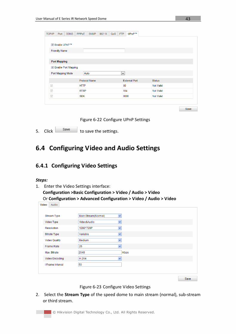
6.3.9 Configuring UPnP Settings............................................................................................. 42
6.4 Configuring Video and Audio Settings ............................................................................... 43
6.4.1 Configuring Video Settings ............................................................................................ 43
6.4.2 Configuring Audio Settings ............................................................................................ 44
6.5 Configuring Image Settings ............................................................................................... 45
6.5.1 Configuring Display Settings .......................................................................................... 45
6.5.2 Configuring OSD Settings .............................................................................................. 51
6.5.3 Configuring Text Overlay Settings .................................................................................. 53
6.6 Configuring and Handling Alarms ...................................................................................... 53
6.6.1 Configuring Motion Detection ....................................................................................... 54
6.6.2 Configuring Tamper-proof Alarm ................................................................................... 57
6.6.3 Configuring External Alarm Input .................................................................................. 58
6.6.4 Configuring Alarm Output ............................................................................................. 60
6.6.5 Handling Exception ....................................................................................................... 61
6.6.6 Configuring Email Settings ............................................................................................ 62
6.6.7 Configuring Snapshot Settings ....................................................................................... 63
Chapter 7 Record Settings ........................................................................................................ 65
7.1 Configuring NAS Settings................................................................................................... 65
7.2 Configuring Recording Schedule ........................................................................................ 66
Chapter 8 Playback ................................................................................................................... 71
Chapter 9 Log Searching ........................................................................................................... 75
Chapter 10 Others ...................................................................................................................... 77
10.1 Managing User Accounts .................................................................................................. 77
10.2 Configuring RTSP Authentication ....................................................................................... 80
10.3 Configuring Anonymous Visit ............................................................................................ 80
10.4 Configuring IP Address Filter ............................................................................................. 81
10.5 Viewing Device Information .............................................................................................. 81
10.6 Maintenance .................................................................................................................... 82
10.6.1 Rebooting the Speed Dome ...................................................................................... 82
10.6.2 Restoring Default Settings ......................................................................................... 82
10.6.3 Importing/Exporting Configuration File ..................................................................... 83
10.6.4 Upgrading the System ............................................................................................... 83
10.7 RS-232 Settings ................................................................................................................. 84
10.8 RS-485 Settings ................................................................................................................. 85
Appendix ......................................................................................................................................... 86
Appendix 1 SADP Software Introduction ....................................................................................... 86
Appendix 2 Port Mapping ............................................................................................................. 88
User Manual of E Series IR Network Speed Dome
© Hikvision Digital Technology Co., Ltd. All Rights Reserved.
7
Chapter 1 Overview
1.1 System Requirement
System requirement of web browser accessing is as follows:
Operating System: Microsoft Windows XP SP1 and above version / Vista / Win7 /
Server 2003 / Server 2008 32bits
CPU: Intel Pentium IV 3.0 GHz or higher
RAM: 1G or higher
Display: 1024×768 resolution or higher
Web Browser: Internet Explorer 7.0 and above version, Apple Safari 5.02 and above
version, Mozilla Firefox 3.5 and above version and Google Chrome8 and above
versions.
1.2 Functions
Note: The functions vary depending on the models of speed dome.
Scan Modes
The dome provides 5 scan modes: auto scan, tilt scan, frame scan, random scan and
panorama scan.
Presets
A preset is a predefined image position. When the preset is called, the dome will
automatically move to the defined position. The presets can be added, modified,
deleted and called.
Label Display
The on-screen label of the time and dome name can be displayed on the monitor.
The displays of time and speed dome name can be programmed.
Auto Flips
When a target object goes directly beneath the speed dome, operating the speed
dome to monitor the object, the speed dome will automatically rotate 180 degrees in
horizontal direction to maintain continuity of tracking.
3D Positioning
In the client software, use the left key of mouse to click on the desired position in the
video image and drag a rectangle area in the lower right direction, then the dome
system will move the position to the center and allow the rectangle area to zoom in.
Use the left key of mouse to drag a rectangle area in the upper left direction to move
the position to the center and allow the rectangle area to zoom out.
Proportional Pan/Tilt
Proportional pan/tilt automatically reduces or increases the pan and tilt speeds
according to the amount of zoom. At telephoto zoom settings, the pan and tilt
User Manual of E Series IR Network Speed Dome
© Hikvision Digital Technology Co., Ltd. All Rights Reserved.
8
speeds will be slower than at wide zoom settings. This keeps the image from moving
too fast on the live view image when there is a large amount of zoom.
Auto Focus
The auto focus enables the camera to focus automatically to maintain clear video
images.
Day/Night Auto Switch
The speed domes deliver color images during the day. And as light diminishes at night,
the speed domes switch to night mode and deliver black and white images with high
quality.
Slow Shutter
In slow shutter mode, the shutter speed will automatically slow down in low
illumination conditions to maintain clear video images by extending the exposure
time. The feature can be enabled or disabled.
Backlight Compensation (BLC)
If you focus on an object against strong backlight, the object will be too dark to be
seen clearly. The BLC (Backlight Compensation) function can compensate light to the
object in the front to make it clear, but this causes the over-exposure of the
background where the light is strong.
Wide Dynamic Range (WDR)
The wide dynamic range (WDR) function helps the camera provide clear images even
under back light circumstances. When there are both very bright and very dark areas
simultaneously in the field of view, WDR balances the brightness level of the whole
image and provide clear images with details.
Note: This feature varies depending on speed dome models.
White Balance (WB)
White balance can remove the unrealistic color casts. White balance is the white
rendition function of the camera to adjust the color temperature according to the
environment automatically.
Patrol
A patrol is a memorized series of pre-defined preset function. The scanning speed
between two presets and the dwell time at the preset are programmable.
Pattern
A pattern is a memorized series of pan, tilt, zoom, and preset functions. By default
the focus and iris are in auto status during the pattern is being memorized.
Power Off Memory
The dome supports the power off memory capability. It allows the dome to resume
its previous position after power is restored.
Park Action
This feature allows the dome to start a predefined action automatically after a period
of inactivity.
User Management
The dome allows you to edit users with different levels of permission, in the admin
login status. Multiple users are allowed to access and control the same network
speed dome via network simultaneously.
User Manual of E Series IR Network Speed Dome
© Hikvision Digital Technology Co., Ltd. All Rights Reserved.
9
3D Digital Noise Reduction
Comparing with the general 2D digital noise reduction, the 3D digital noise reduction
function processes the noise between two frames besides processing the noise in
one frame. The noise will be much less and the video will be clearer.
User Manual of E Series IR Network Speed Dome
© Hikvision Digital Technology Co., Ltd. All Rights Reserved.
10
Chapter 2 Network Connection Before you start:
If you want to set the network speed dome via a LAN (Local Area Network),
please refer to Section 2.1 Setting the Network Speed Dome over the LAN.
If you want to set the network speed dome via a WAN (Wide Area Network),
please refer to Section 2.2 Setting the Network Speed Dome over the WAN.
2.1 Setting the Network Speed Dome over the LAN
Purpose:
To view and configure the speed dome via a LAN, you need to connect the network
speed dome in the same subnet with your computer, and install the SADP or client
software to search and change the IP of the network speed dome.
Note: For the detailed introduction of SADP, please refer to Appendix 1.
2.1.1 Wiring over the LAN
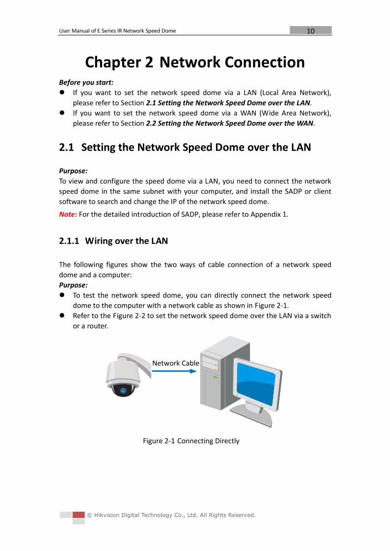
The following figures show the two ways of cable connection of a network speed
dome and a computer:
Purpose:
To test the network speed dome, you can directly connect the network speed
dome to the computer with a network cable as shown in Figure 2-1.
Refer to the Figure 2-2 to set the network speed dome over the LAN via a switch
or a router.
Figure 2-1 Connecting Directly
Network Cable
User Manual of E Series IR Network Speed Dome
© Hikvision Digital Technology Co., Ltd. All Rights Reserved.
11
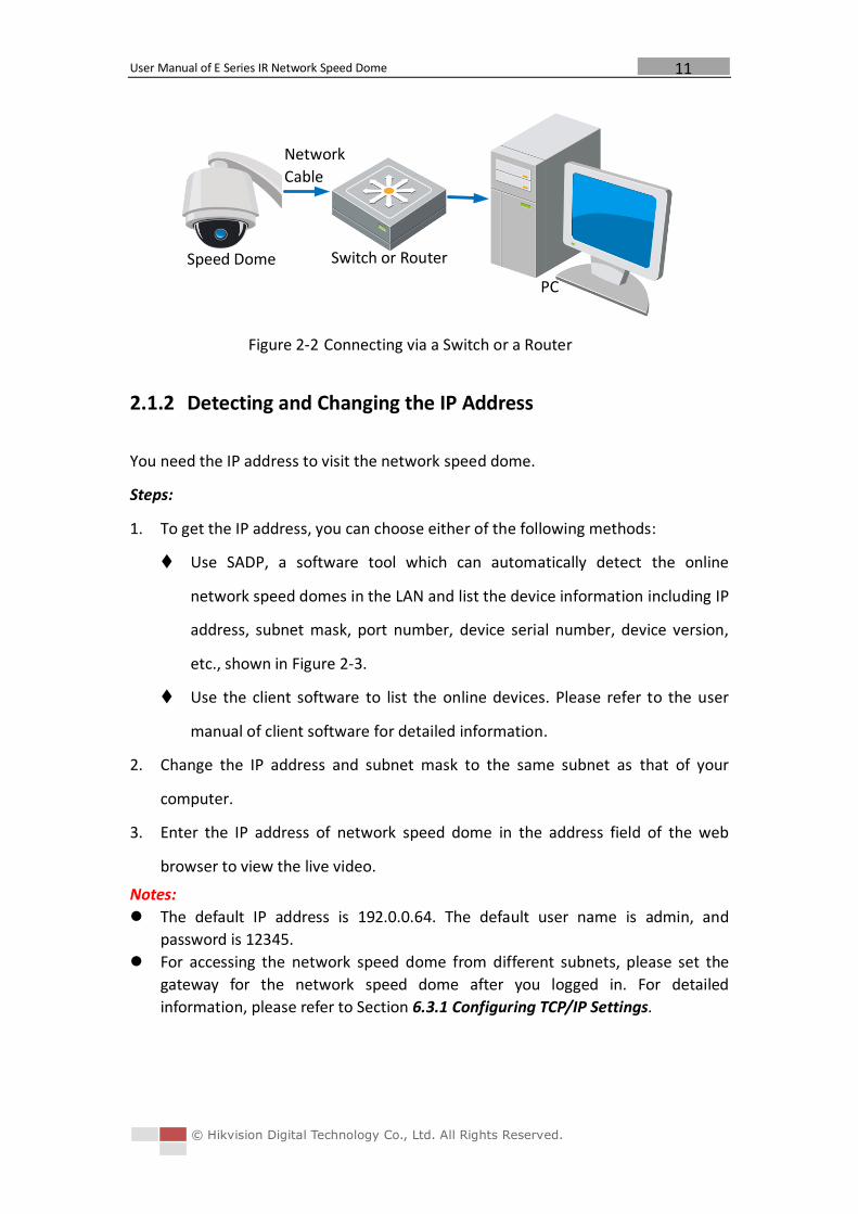
Figure 2-2 Connecting via a Switch or a Router
2.1.2 Detecting and Changing the IP Address
You need the IP address to visit the network speed dome.
Steps:
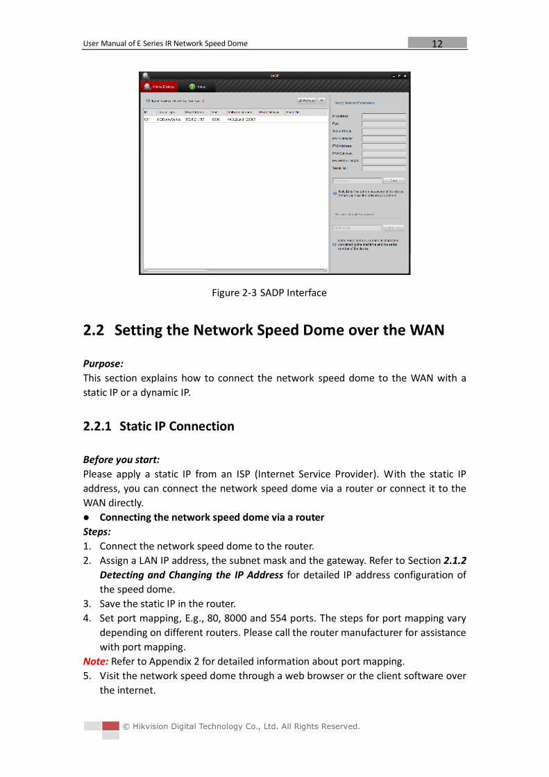
1. To get the IP address, you can choose either of the following methods:
Use SADP, a software tool which can automatically detect the online
network speed domes in the LAN and list the device information including IP
address, subnet mask, port number, device serial number, device version,
etc., shown in Figure 2-3.
Use the client software to list the online devices. Please refer to the user
manual of client software for detailed information.
2. Change the IP address and subnet mask to the same subnet as that of your
computer.
3. Enter the IP address of network speed dome in the address field of the web
browser to view the live video.
Notes:
The default IP address is 192.0.0.64. The default user name is admin, and
password is 12345.
For accessing the network speed dome from different subnets, please set the
gateway for the network speed dome after you logged in. For detailed
information, please refer to Section 6.3.1 Configuring TCP/IP Settings.
Speed Dome
PC
Network
Cable
Switch or Router
User Manual of E Series IR Network Speed Dome
© Hikvision Digital Technology Co., Ltd. All Rights Reserved.
12
Figure 2-3 SADP Interface
2.2 Setting the Network Speed Dome over the WAN
Purpose:
This section explains how to connect the network speed dome to the WAN with a
static IP or a dynamic IP.
2.2.1 Static IP Connection
Before you start:
Please apply a static IP from an ISP (Internet Service Provider). With the static IP
address, you can connect the network speed dome via a router or connect it to the
WAN directly.
Connecting the network speed dome via a router
Steps:
1. Connect the network speed dome to the router.
2. Assign a LAN IP address, the subnet mask and the gateway. Refer to Section 2.1.2
Detecting and Changing the IP Address for detailed IP address configuration of
the speed dome.
3. Save the static IP in the router.
4. Set port mapping, E.g., 80, 8000 and 554 ports. The steps for port mapping vary
depending on different routers. Please call the router manufacturer for assistance
with port mapping.
Note: Refer to Appendix 2 for detailed information about port mapping.
5. Visit the network speed dome through a web browser or the client software over
the internet.
User Manual of E Series IR Network Speed Dome
© Hikvision Digital Technology Co., Ltd. All Rights Reserved.
13
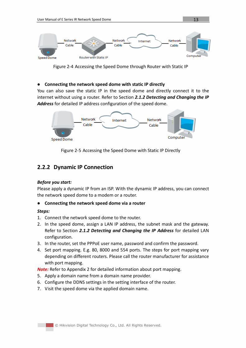
Figure 2-4 Accessing the Speed Dome through Router with Static IP
Connecting the network speed dome with static IP directly
You can also save the static IP in the speed dome and directly connect it to the
internet without using a router. Refer to Section 2.1.2 Detecting and Changing the IP
Address for detailed IP address configuration of the speed dome.
Figure 2-5 Accessing the Speed Dome with Static IP Directly
2.2.2 Dynamic IP Connection
Before you start:
Please apply a dynamic IP from an ISP. With the dynamic IP address, you can connect
the network speed dome to a modem or a router.
Connecting the network speed dome via a router
Steps:
1. Connect the network speed dome to the router.
2. In the speed dome, assign a LAN IP address, the subnet mask and the gateway.
Refer to Section 2.1.2 Detecting and Changing the IP Address for detailed LAN
configuration.
3. In the router, set the PPPoE user name, password and confirm the password.
4. Set port mapping. E.g. 80, 8000 and 554 ports. The steps for port mapping vary
depending on different routers. Please call the router manufacturer for assistance
with port mapping.
Note: Refer to Appendix 2 for detailed information about port mapping.
5. Apply a domain name from a domain name provider.
6. Configure the DDNS settings in the setting interface of the router.
7. Visit the speed dome via the applied domain name.
User Manual of E Series IR Network Speed Dome
© Hikvision Digital Technology Co., Ltd. All Rights Reserved.
14
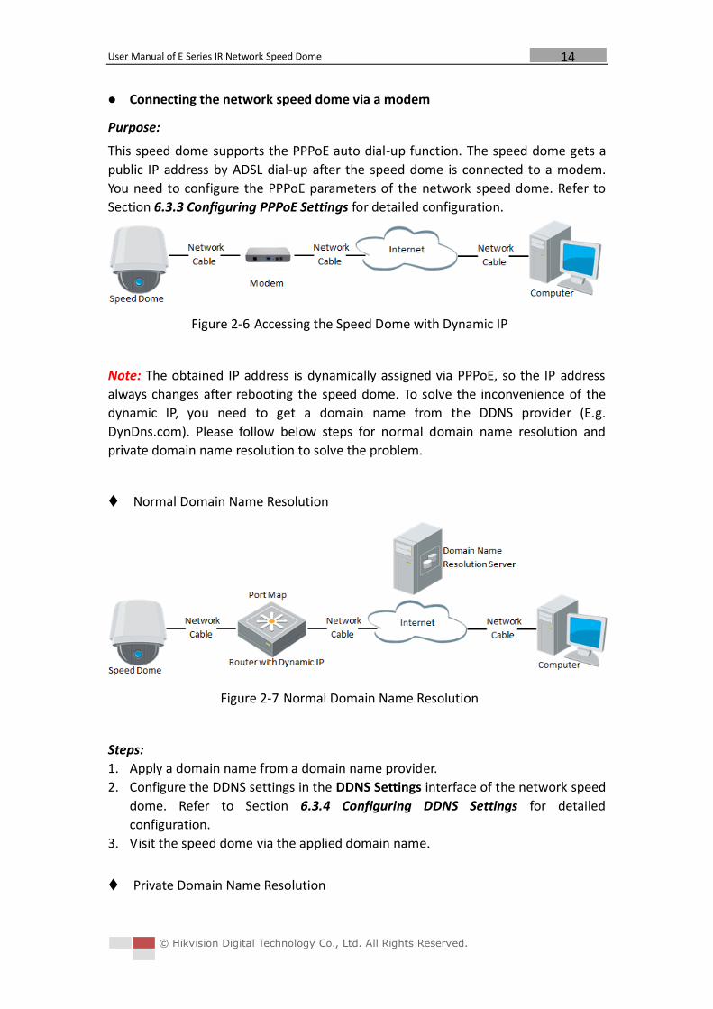
Connecting the network speed dome via a modem
Purpose:
This speed dome supports the PPPoE auto dial-up function. The speed dome gets a
public IP address by ADSL dial-up after the speed dome is connected to a modem.
You need to configure the PPPoE parameters of the network speed dome. Refer to
Section 6.3.3 Configuring PPPoE Settings for detailed configuration.
Figure 2-6 Accessing the Speed Dome with Dynamic IP
Note: The obtained IP address is dynamically assigned via PPPoE, so the IP address
always changes after rebooting the speed dome. To solve the inconvenience of the
dynamic IP, you need to get a domain name from the DDNS provider (E.g.
DynDns.com). Please follow below steps for normal domain name resolution and
private domain name resolution to solve the problem.
Normal Domain Name Resolution
Figure 2-7 Normal Domain Name Resolution
Steps:
1. Apply a domain name from a domain name provider.
2. Configure the DDNS settings in the DDNS Settings interface of the network speed
dome. Refer to Section 6.3.4 Configuring DDNS Settings for detailed
configuration.
3. Visit the speed dome via the applied domain name.
Private Domain Name Resolution
User Manual of E Series IR Network Speed Dome
© Hikvision Digital Technology Co., Ltd. All Rights Reserved.
15
Figure 2-8 Private Domain Name Resolution
Steps:
1. Install and run the IP Server software in a computer with a static IP.
2. Access the network speed dome through the LAN with a web browser or the
client software.
3. Enable DDNS and select IP Server as the protocol type. Refer to Section 6.3.4
Configuring DDNS Settings for detailed configuration.
User Manual of E Series IR Network Speed Dome
© Hikvision Digital Technology Co., Ltd. All Rights Reserved.
16
Chapter 3 Access to the Network
Speed Dome
3.1 Accessing by Web Browsers
Steps:
1. Open the web browser.
2. In the address field, input the IP address of the network speed dome, e.g.,
192.0.0.64 and press the Enter key to enter the login interface.
3. Input the user name and password and click .
Note: The default user name is admin, password is 12345.
Figure 3-1 Login Interface
4. Install the plug-in before viewing the live video and operating the speed dome.
Please follow the installation prompts to install the plug-in.
User Manual of E Series IR Network Speed Dome
© Hikvision Digital Technology Co., Ltd. All Rights Reserved.
17
Figure 3-2 Download and Install Plug-in
Figure 3-3 Install Plug-in (1)
Figure 3-4 Install Plug-in (2)
User Manual of E Series IR Network Speed Dome
© Hikvision Digital Technology Co., Ltd. All Rights Reserved.
18
Figure 3-5 Install Plug-in (3)
Note: You may have to close the web browser to install the plug-in. Please reopen
the web browser and log in again after installing the plug-in.
3.2 Accessing by Client Software
The product CD contains the client software. You can view the live video and manage
the speed dome with the client software.
Follow the installation prompts to install the client software and WinPcap. The
configuration interface and live view interface of client software are shown bellow.
Figure 3-6 iVMS-4200 PCNVR Control Panel
User Manual of E Series IR Network Speed Dome
© Hikvision Digital Technology Co., Ltd. All Rights Reserved.
19
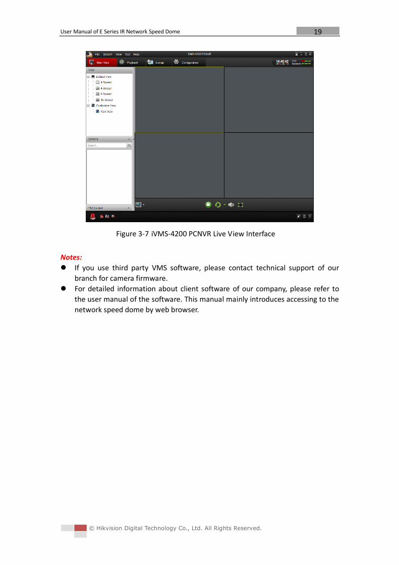
Figure 3-7 iVMS-4200 PCNVR Live View Interface
Notes:
If you use third party VMS software, please contact technical support of our
branch for camera firmware.
For detailed information about client software of our company, please refer to
the user manual of the software. This manual mainly introduces accessing to the
network speed dome by web browser.
User Manual of E Series IR Network Speed Dome
© Hikvision Digital Technology Co., Ltd. All Rights Reserved.
20
Chapter 4 Live View
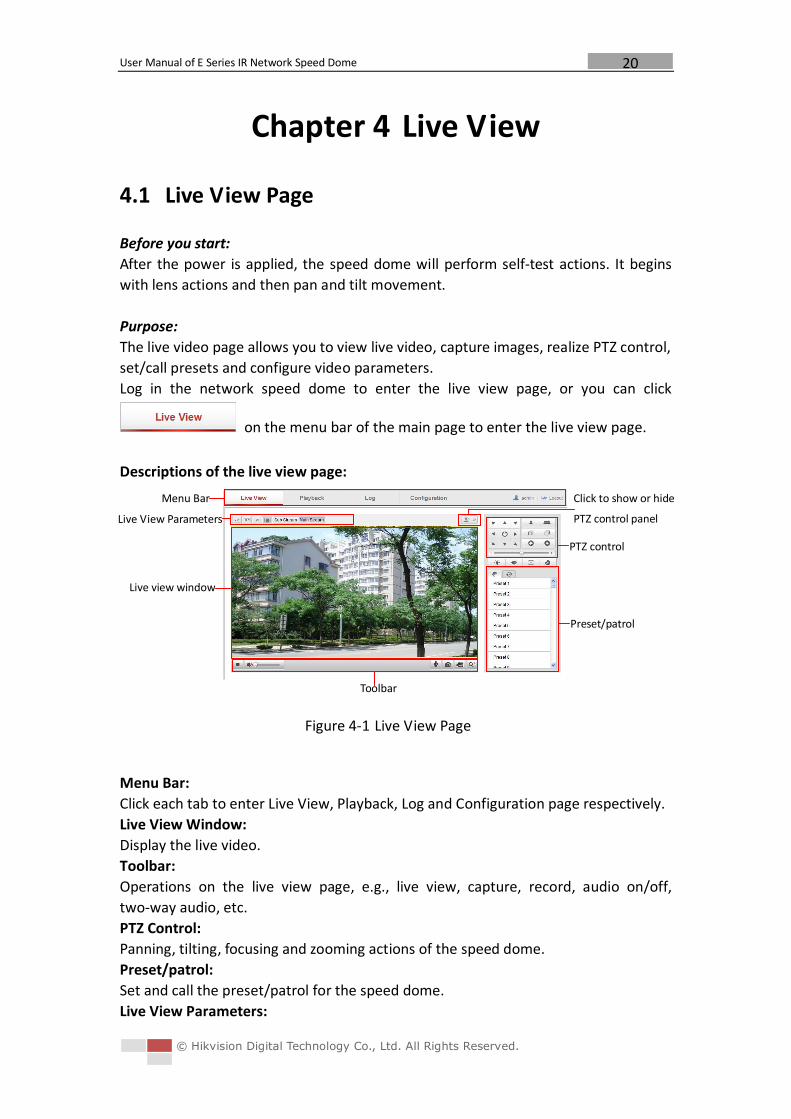
4.1 Live View Page
Before you start:
After the power is applied, the speed dome will perform self-test actions. It begins
with lens actions and then pan and tilt movement.
Purpose:
The live video page allows you to view live video, capture images, realize PTZ control,
set/call presets and configure video parameters.
Log in the network speed dome to enter the live view page, or you can click
on the menu bar of the main page to enter the live view page.
Descriptions of the live view page:
Figure 4-1 Live View Page
Menu Bar:
Click each tab to enter Live View, Playback, Log and Configuration page respectively.
Live View Window:
Display the live video.
Toolbar:
Operations on the live view page, e.g., live view, capture, record, audio on/off,
two-way audio, etc.
PTZ Control:
Panning, tilting, focusing and zooming actions of the speed dome.
Preset/patrol:
Set and call the preset/patrol for the speed dome.
Live View Parameters:
Menu Bar
Live view window
Toolbar
PTZ control
Preset/patrol
Live View Parameters
Click to show or hide
PTZ control panel
User Manual of E Series IR Network Speed Dome
© Hikvision Digital Technology Co., Ltd. All Rights Reserved.
21
Configure the image size and stream type of the live video.
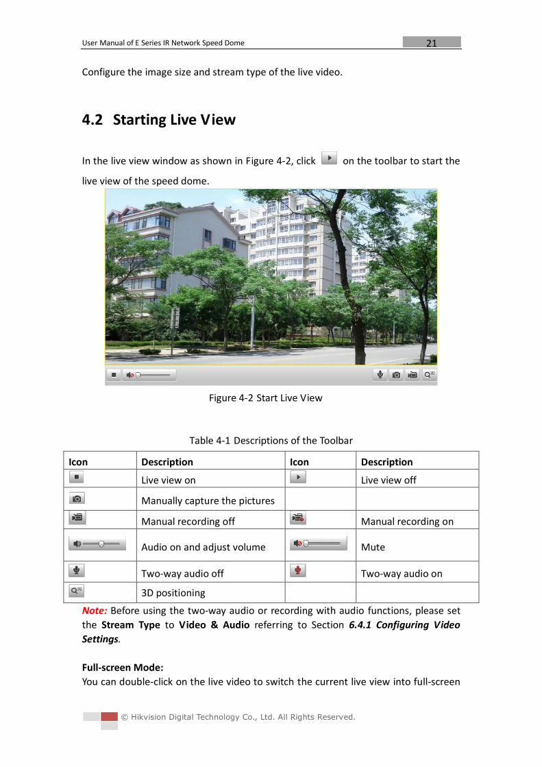
4.2 Starting Live View
In the live view window as shown in Figure 4-2, click on the toolbar to start the
live view of the speed dome.
Figure 4-2 Start Live View
Table 4-1 Descriptions of the Toolbar
Icon Description Icon Description
Live view on Live view off
Manually capture the pictures
Manual recording off Manual recording on
Audio on and adjust volume Mute
Two-way audio off Two-way audio on
3D positioning
Note: Before using the two-way audio or recording with audio functions, please set
the Stream Type to Video & Audio referring to Section 6.4.1 Configuring Video
Settings.
Full-screen Mode:
You can double-click on the live video to switch the current live view into full-screen
User Manual of E Series IR Network Speed Dome
© Hikvision Digital Technology Co., Ltd. All Rights Reserved.
22
or return to normal mode from the full-screen.
3D Positioning:
Steps:
1. Click on the tool bar of live view interface.
2. Operate the 3D positioning function:
Left click a position of the live video. The corresponding position will be
moved to the center of the live video.
Hold down the left mouse button and drag the mouse to the lower right on
the live video. The corresponding position will be moved to the center of the live
video and zoomed in.
Hold down the left mouse button and drag the mouse to the upper left on
the live video. The corresponding position will be moved to the center of the live
video and zoomed out.
Please refer to the following sections for more information:
Configuring remote recording in Section 7.2 Configuring Recording Schedule.
Setting the image quality of the live video in Section 6.1 Configuring Local
Parameters and Section 6.4.1 Configuring Video Settings.
Setting the OSD text on live video in Section 6.5.2 Configuring OSD Settings.
4.3 Recording and Capturing Pictures Manually
In the live view interface, click on the toolbar to capture the live pictures or
click to record the live video. The local saving paths of the captured pictures
and clips can be set in the Configuration > Local Configuration interface.
To configure remote automatic recording, please refer to Section 7.2 Configuring
Recording Schedule.
Note: The captured image will be saved as a JPEG file in your computer.
4.4 Operating PTZ Control
Purpose:
In the live view interface, you can use the PTZ control buttons to control panning,
tilting and zooming.
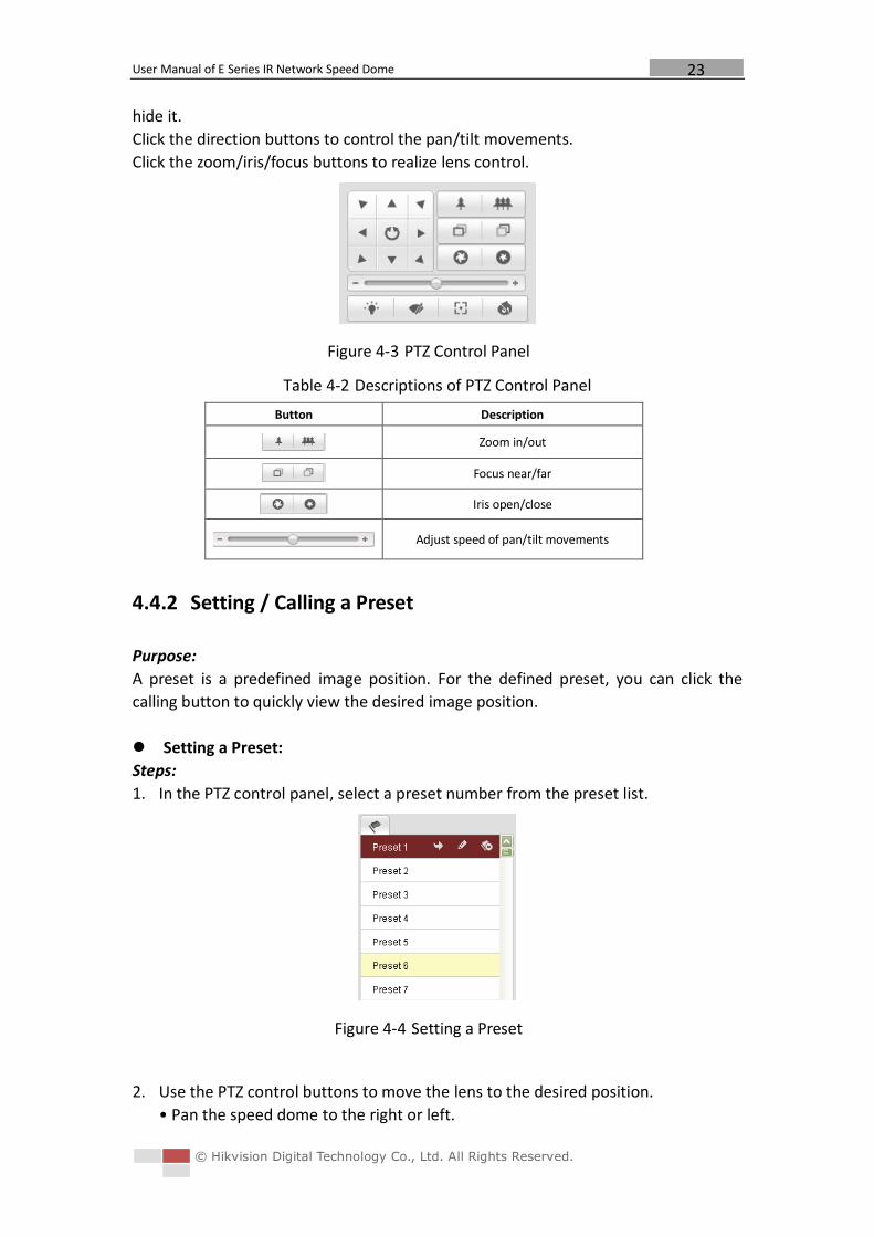
4.4.1 PTZ Control Panel
On the live view page, click to show the PTZ control panel or click to
User Manual of E Series IR Network Speed Dome
© Hikvision Digital Technology Co., Ltd. All Rights Reserved.
23
hide it.
Click the direction buttons to control the pan/tilt movements.
Click the zoom/iris/focus buttons to realize lens control.
Figure 4-3 PTZ Control Panel
Table 4-2 Descriptions of PTZ Control Panel
Button Description
Zoom in/out
Focus near/far
Iris open/close
Adjust speed of pan/tilt movements
4.4.2 Setting / Calling a Preset
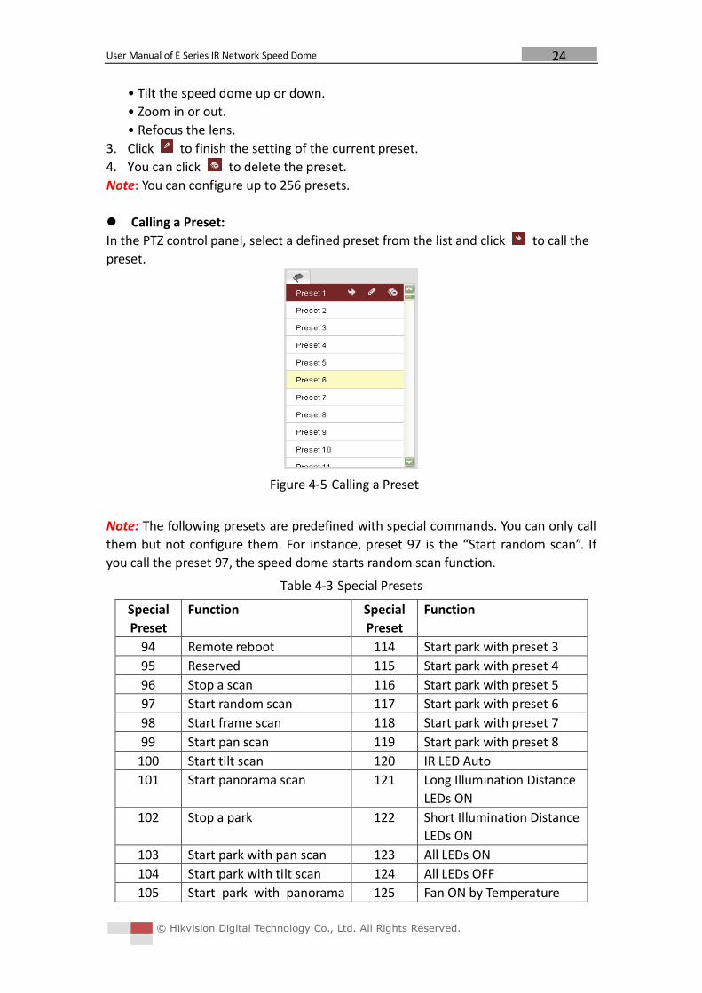
Purpose:
A preset is a predefined image position. For the defined preset, you can click the
calling button to quickly view the desired image position.
Setting a Preset:
Steps:
1. In the PTZ control panel, select a preset number from the preset list.
Figure 4-4 Setting a Preset
2. Use the PTZ control buttons to move the lens to the desired position.
• Pan the speed dome to the right or left.
User Manual of E Series IR Network Speed Dome
© Hikvision Digital Technology Co., Ltd. All Rights Reserved.
24
• Tilt the speed dome up or down.
• Zoom in or out.
• Refocus the lens.
3. Click to finish the setting of the current preset.
4. You can click to delete the preset.
Note: You can configure up to 256 presets.
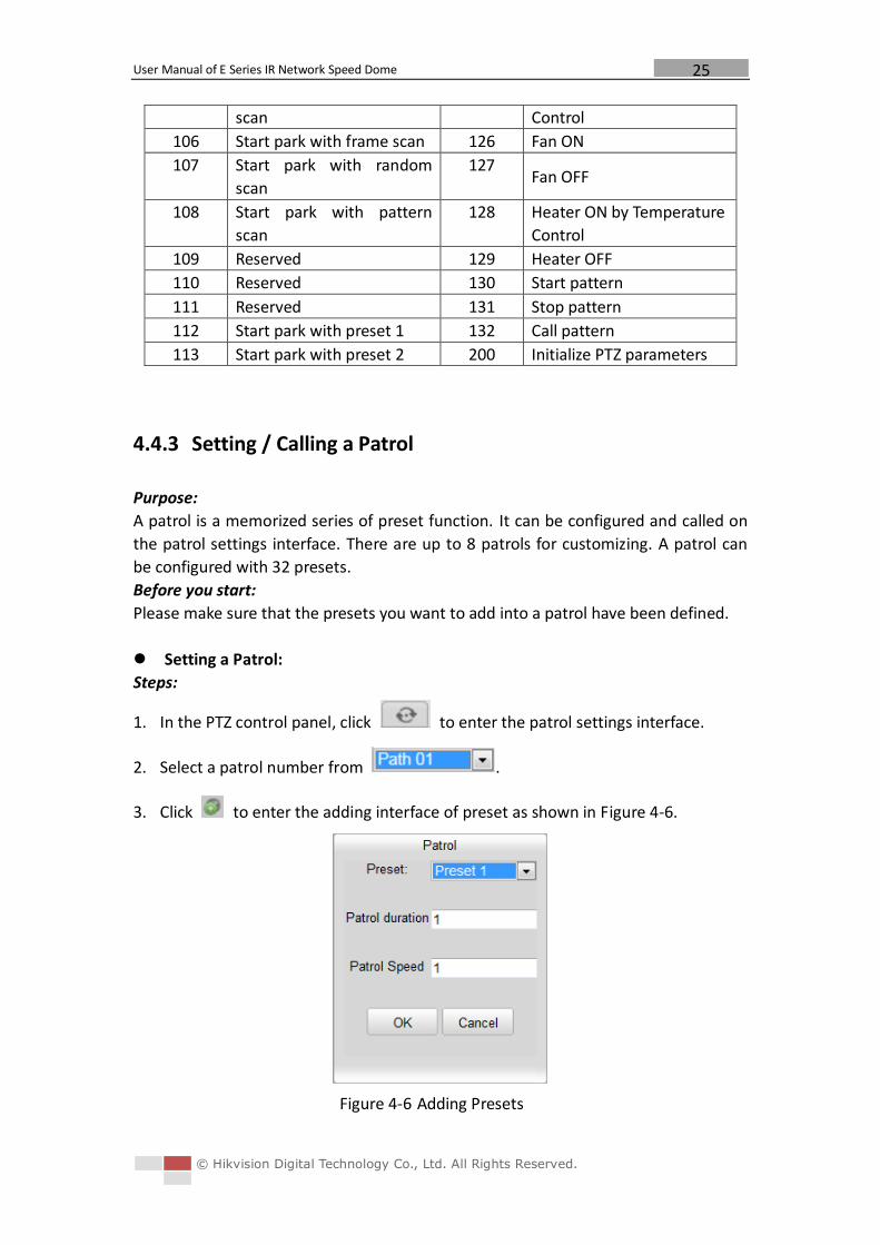
Calling a Preset:
In the PTZ control panel, select a defined preset from the list and click to call the
preset.
Figure 4-5 Calling a Preset
Note: The following presets are predefined with special commands. You can only call
them but not configure them. For instance, preset 97 is the “Start random scan”. If
you call the preset 97, the speed dome starts random scan function.
Table 4-3 Special Presets
Special
Preset
Function Special
Preset
Function
94 Remote reboot 114 Start park with preset 3
95 Reserved 115 Start park with preset 4
96 Stop a scan 116 Start park with preset 5
97 Start random scan 117 Start park with preset 6
98 Start frame scan 118 Start park with preset 7
99 Start pan scan 119 Start park with preset 8
100 Start tilt scan 120 IR LED Auto
101 Start panorama scan 121 Long Illumination Distance
LEDs ON
102 Stop a park 122 Short Illumination Distance
LEDs ON
103 Start park with pan scan 123 All LEDs ON
104 Start park with tilt scan 124 All LEDs OFF
105 Start park with panorama 125 Fan ON by Temperature
User Manual of E Series IR Network Speed Dome
© Hikvision Digital Technology Co., Ltd. All Rights Reserved.
25
scan Control
106 Start park with frame scan 126 Fan ON
107 Start park with random
scan
127 Fan OFF
108 Start park with pattern
scan
128 Heater ON by Temperature
Control
109 Reserved 129 Heater OFF
110 Reserved 130 Start pattern
111 Reserved 131 Stop pattern
112 Start park with preset 1 132 Call pattern
113 Start park with preset 2 200 Initialize PTZ parameters
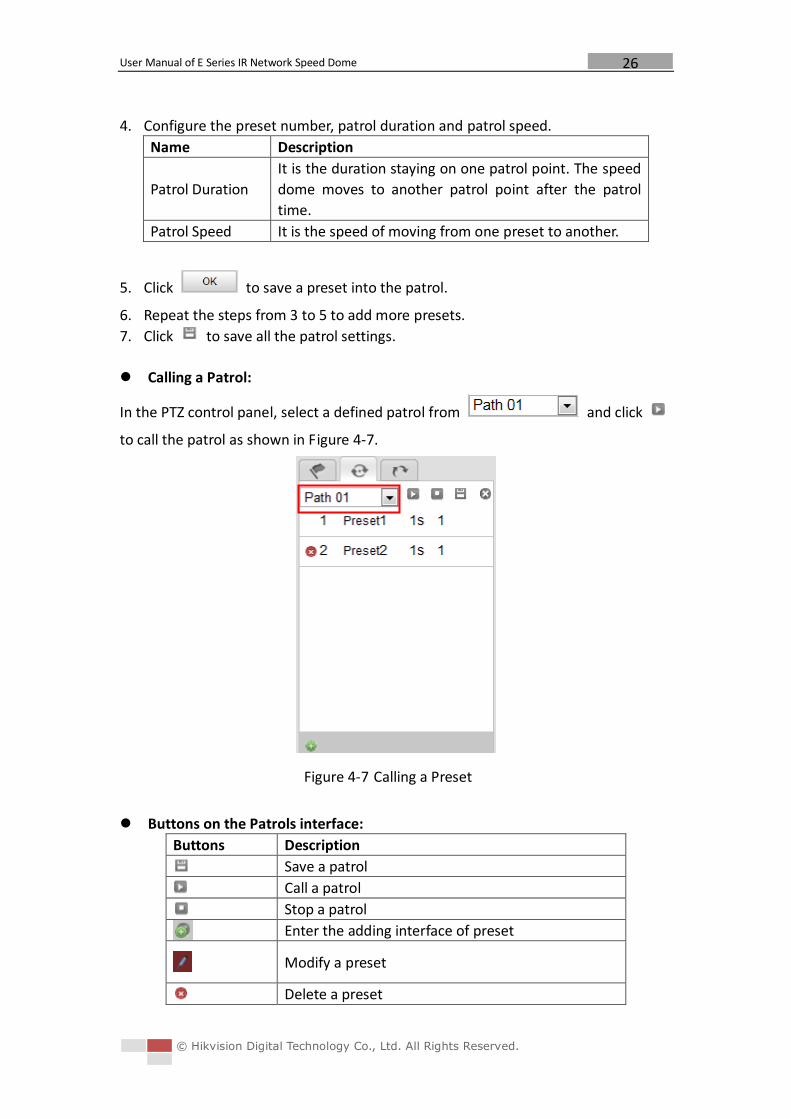
4.4.3 Setting / Calling a Patrol
Purpose:
A patrol is a memorized series of preset function. It can be configured and called on
the patrol settings interface. There are up to 8 patrols for customizing. A patrol can
be configured with 32 presets.
Before you start:
Please make sure that the presets you want to add into a patrol have been defined.
Setting a Patrol:
Steps:
1. In the PTZ control panel, click to enter the patrol settings interface.
2. Select a patrol number from .
3. Click to enter the adding interface of preset as shown in Figure 4-6.
Figure 4-6 Adding Presets
User Manual of E Series IR Network Speed Dome
© Hikvision Digital Technology Co., Ltd. All Rights Reserved.
26
4. Configure the preset number, patrol duration and patrol speed.
Name Description
Patrol Duration
It is the duration staying on one patrol point. The speed
dome moves to another patrol point after the patrol
time.
Patrol Speed It is the speed of moving from one preset to another.
5. Click to save a preset into the patrol.
6. Repeat the steps from 3 to 5 to add more presets.
7. Click to save all the patrol settings.
Calling a Patrol:
In the PTZ control panel, select a defined patrol from and click
to call the patrol as shown in Figure 4-7.
Figure 4-7 Calling a Preset
Buttons on the Patrols interface:
Buttons Description
Save a patrol
Call a patrol
Stop a patrol
Enter the adding interface of preset
Modify a preset
Delete a preset
User Manual of E Series IR Network Speed Dome
© Hikvision Digital Technology Co., Ltd. All Rights Reserved.
27
Delete all the presets in one patrol
4.4.4 Setting / Calling a Pattern
Purpose:
A pattern is a memorized series of pan, tilt and zoom functions. It can be called with
system-defined preset.
Setting a Pattern:
Steps:
1. Call preset 130 to start a pattern.
2. Control the PTZ to set a motion route as the pattern route.
3. Call preset 131 to save the pattern.
Then you can call preset 132 to call the pattern.
4.5 Configuring Live View Parameters
Main stream/Sub-stream/Third stream:
You can select or as the stream type of live viewing.
The main stream is with a relatively high resolution and needs much bandwidth. The
sub-stream is with a low resolution and needs less bandwidth. The default setting of
stream type is .
Note: Please refer to Section 6.4.1 Configuring Video Settings for more detailed
parameter settings of the main stream and sub-stream respectively.
Image Size:
You can scale up/down the live view image by clicking . the
image size can be 4:3, 16:9, original or auto.
User Manual of E Series IR Network Speed Dome
© Hikvision Digital Technology Co., Ltd. All Rights Reserved.
28
Chapter 5 PTZ Configuration Purpose:
The section lists the system-defined presets with PTZ functions. These presets cannot
be edited but only called through a control device e.g. a DVR or web browser. To call
the system-defined presets remotely, you can choose the preset number from the list
in the PTZ control panel. Please refer to below tables for details.
5.1 Scan Mode
The corresponding scan modes and presets are as follows:
Scan Mode Description
Stop Scanning Call preset 96 to stop scanning.
Random Scan Call preset 97. The speed dome scans
randomly.
Frame Scan Call preset 98. The speed dome scans by
frames.
Pan Scan Call preset 99. The speed dome scans in
the pan direction.
Tilt Scan Call preset 100. The speed dome scans in
the tilt direction.
Panorama Scan Call preset 101. The speed dome scans
panoramically.
5.2 Park Action
The speed dome starts a predefined scan, pattern or preset after a period of
inactivity. The corresponding park action modes and presets are as follows:
Mode Description
Park Action OFF Call preset 102 to stop park action.
Park Action with Pan Scan Call preset 103.
Park Action with Tilt Scan Call preset 104.
Park Action with Panorama
Scan Call preset 105.
Park Action with Frame Scan Call preset 106.
Park Action with Random Scan Call preset 107.
Park Action with Pattern Call preset 108.
Park Action with Preset
1/2/3/4/5/6/7/8
Call preset
112/113/114/115/116/117/118/119.
User Manual of E Series IR Network Speed Dome
© Hikvision Digital Technology Co., Ltd. All Rights Reserved.
29
Chapter 6 Speed Dome Configuration
6.1 Configuring Local Parameters
Note: The local configuration refers to the parameters of the live view and other
operations using the web browser.
Steps:
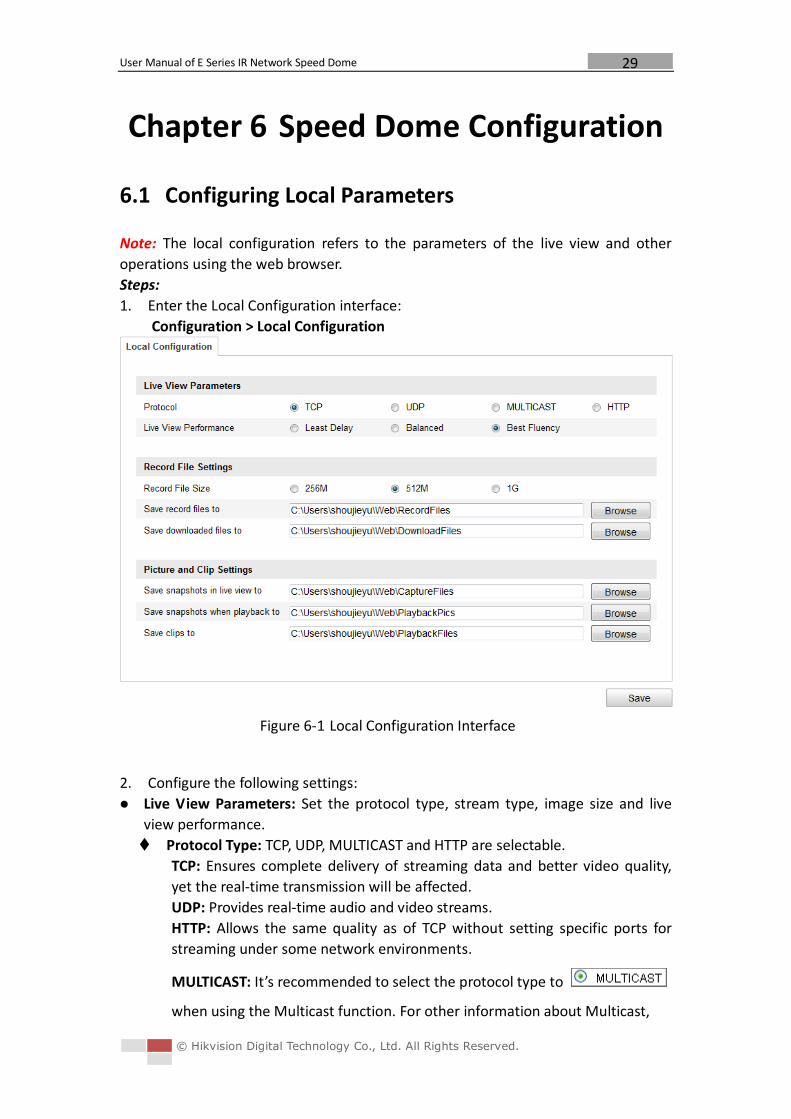
1. Enter the Local Configuration interface:
Configuration > Local Configuration
Figure 6-1 Local Configuration Interface
2. Configure the following settings:
Live View Parameters: Set the protocol type, stream type, image size and live
view performance.
Protocol Type: TCP, UDP, MULTICAST and HTTP are selectable.
TCP: Ensures complete delivery of streaming data and better video quality,
yet the real-time transmission will be affected.
UDP: Provides real-time audio and video streams.
HTTP: Allows the same quality as of TCP without setting specific ports for
streaming under some network environments.
MULTICAST: It’s recommended to select the protocol type to
when using the Multicast function. For other information about Multicast,
User Manual of E Series IR Network Speed Dome
© Hikvision Digital Technology Co., Ltd. All Rights Reserved.
30
refer to Section 6.3.1 Configuring TCP/IP Settings.
Live View Performance: Set the live view performance to Least Delay,
Balanced or Best Fluency.
Record File Settings: Set the saving path of the video files.
Record File Size: Select the packed size of manually recorded and downloaded
video files. The size can be set to 256M, 512M or 1G.
Save record files to: Set the saving path for the manually recorded video files.
Save downloaded files to: Set the saving path for the downloaded video files
in interface.
Picture and Clip Settings: Set the saving paths of the captured pictures and
clipped video files.
Save snapshots in live view to: Set the saving path of the manually captured
pictures in interface.
Save snapshots when playback to: Set the saving path of the captured
pictures in interface.
Save clips to: Set the saving path of the clipped video files in
interface.
Note: You can click to change the directory for saving video files, clips
and pictures.
3. Click to save the settings.
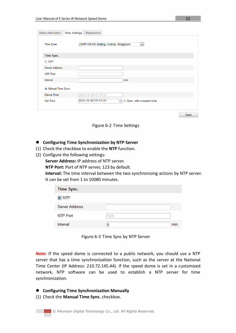
6.2 Configuring Time Settings
Purpose:
You can follow the instructions in this section to configure the time which can be
displayed on the video. There are Time Zone, Time Synchronization, Daylight Saving
Time(DST) functions for setting the time. Time Synchronization consists of auto
mode by Network Time Protocol(NTP) server and manual mode.
To enter the Time Settings interface:
Configuration > Basic Configuration > System > Time Settings
Or Configuration > Advanced Configuration > System > Time Settings
User Manual of E Series IR Network Speed Dome
© Hikvision Digital Technology Co., Ltd. All Rights Reserved.
31
Figure 6-2 Time Settings
Configuring Time Synchronization by NTP Server
(1) Check the checkbox to enable the NTP function.
(2) Configure the following settings:
Server Address: IP address of NTP server.
NTP Port: Port of NTP server, 123 by default.
Interval: The time interval between the two synchronizing actions by NTP server.
It can be set from 1 to 10080 minutes.
Figure 6-3 Time Sync by NTP Server
Note: If the speed dome is connected to a public network, you should use a NTP
server that has a time synchronization function, such as the server at the National
Time Center (IP Address: 210.72.145.44). If the speed dome is set in a customized
network, NTP software can be used to establish a NTP server for time
synchronization.
Configuring Time Synchronization Manually
(1) Check the Manual Time Sync. checkbox.
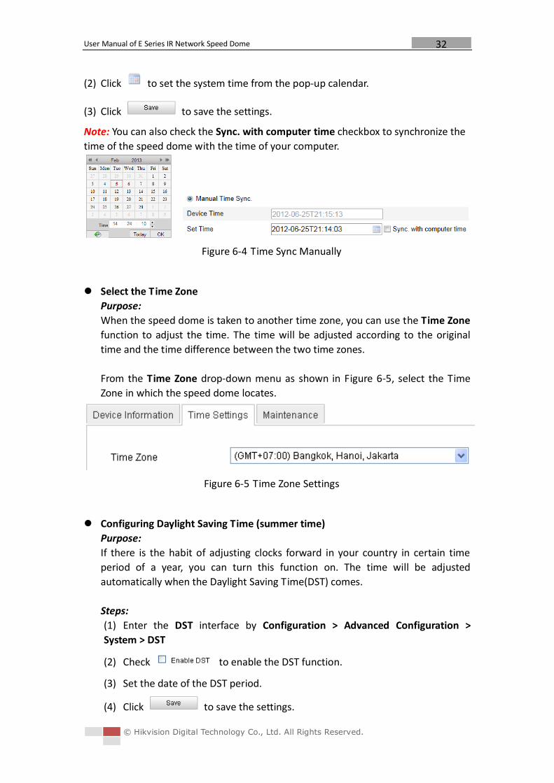
User Manual of E Series IR Network Speed Dome
© Hikvision Digital Technology Co., Ltd. All Rights Reserved.
32
(2) Click to set the system time from the pop-up calendar.
(3) Click to save the settings.
Note: You can also check the Sync. with computer time checkbox to synchronize the
time of the speed dome with the time of your computer.
Figure 6-4 Time Sync Manually
Select the Time Zone
Purpose:
When the speed dome is taken to another time zone, you can use the Time Zone
function to adjust the time. The time will be adjusted according to the original
time and the time difference between the two time zones.
From the Time Zone drop-down menu as shown in Figure 6-5, select the Time
Zone in which the speed dome locates.
Figure 6-5 Time Zone Settings
Configuring Daylight Saving Time (summer time)
Purpose:
If there is the habit of adjusting clocks forward in your country in certain time
period of a year, you can turn this function on. The time will be adjusted
automatically when the Daylight Saving Time(DST) comes.
Steps:
(1) Enter the DST interface by Configuration > Advanced Configuration >
System > DST
(2) Check to enable the DST function.
(3) Set the date of the DST period.
(4) Click to save the settings.
User Manual of E Series IR Network Speed Dome
© Hikvision Digital Technology Co., Ltd. All Rights Reserved.
33
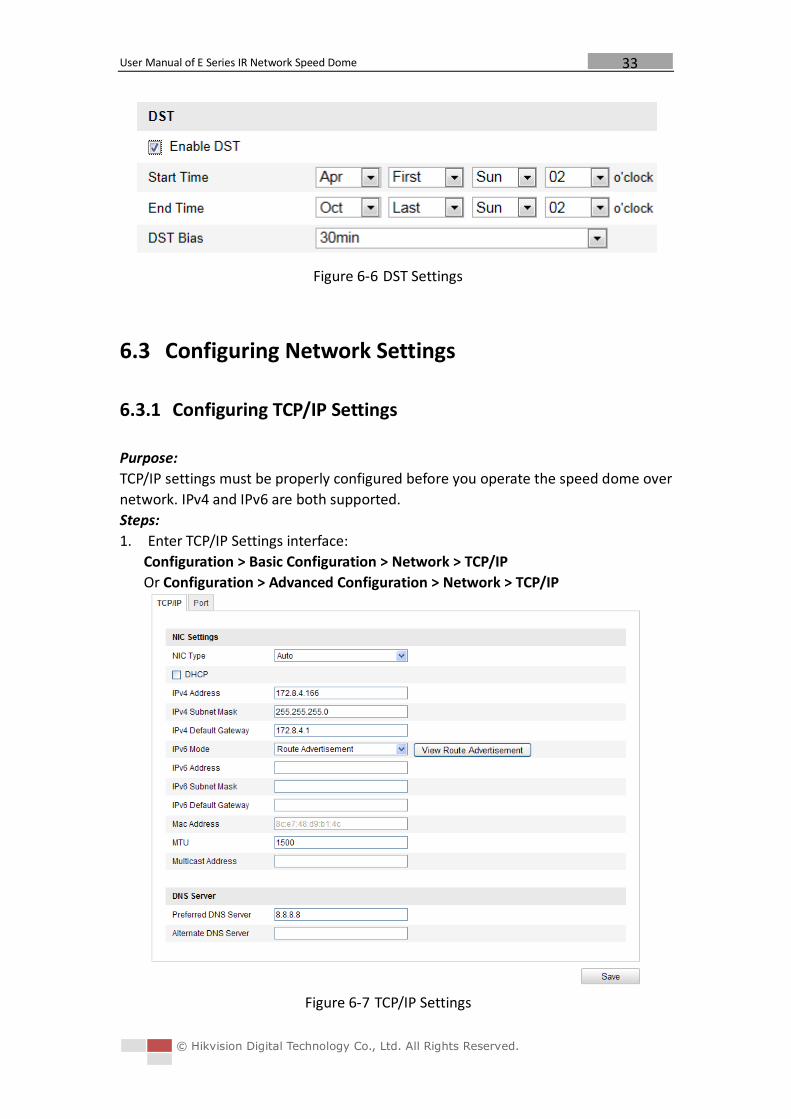
Figure 6-6 DST Settings
6.3 Configuring Network Settings
6.3.1 Configuring TCP/IP Settings
Purpose:
TCP/IP settings must be properly configured before you operate the speed dome over
network. IPv4 and IPv6 are both supported.
Steps:
1. Enter TCP/IP Settings interface:
Configuration > Basic Configuration > Network > TCP/IP
Or Configuration > Advanced Configuration > Network > TCP/IP
Figure 6-7 TCP/IP Settings
User Manual of E Series IR Network Speed Dome
© Hikvision Digital Technology Co., Ltd. All Rights Reserved.
34
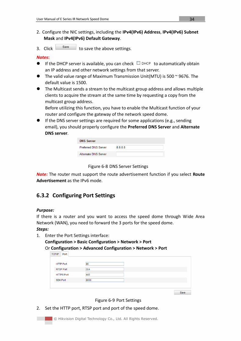
2. Configure the NIC settings, including the IPv4(IPv6) Address, IPv4(IPv6) Subnet
Mask and IPv4(IPv6) Default Gateway.
3. Click to save the above settings.
Notes:
If the DHCP server is available, you can check to automatically obtain
an IP address and other network settings from that server.
The valid value range of Maximum Transmission Unit(MTU) is 500 ~ 9676. The
default value is 1500.
The Multicast sends a stream to the multicast group address and allows multiple
clients to acquire the stream at the same time by requesting a copy from the
multicast group address.
Before utilizing this function, you have to enable the Multicast function of your
router and configure the gateway of the network speed dome.
If the DNS server settings are required for some applications (e.g., sending
email), you should properly configure the Preferred DNS Server and Alternate
DNS server.
Figure 6-8 DNS Server Settings
Note: The router must support the route advertisement function if you select Route
Advertisement as the IPv6 mode.
6.3.2 Configuring Port Settings
Purpose:
If there is a router and you want to access the speed dome through Wide Area
Network (WAN), you need to forward the 3 ports for the speed dome.
Steps:
1. Enter the Port Settings interface:
Configuration > Basic Configuration > Network > Port
Or Configuration > Advanced Configuration > Network > Port
Figure 6-9 Port Settings
2. Set the HTTP port, RTSP port and port of the speed dome.
User Manual of E Series IR Network Speed Dome
© Hikvision Digital Technology Co., Ltd. All Rights Reserved.
35
HTTP Port: The default port number is 80.
RTSP Port: The default port number is 554.
HTTPS Port: The default port number is 443.
SDK Port: The default port number is 8000.
3. Click to save the settings.
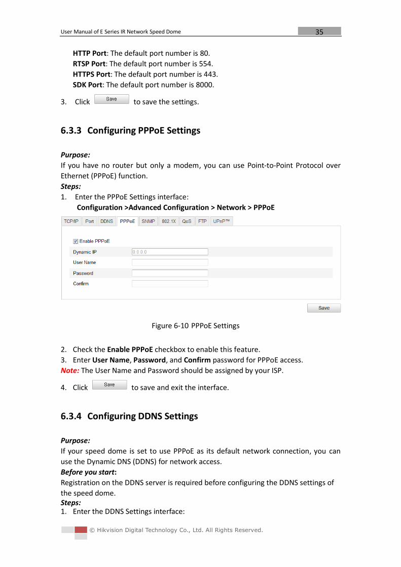
6.3.3 Configuring PPPoE Settings
Purpose:
If you have no router but only a modem, you can use Point-to-Point Protocol over
Ethernet (PPPoE) function.
Steps:
1. Enter the PPPoE Settings interface:
Configuration >Advanced Configuration > Network > PPPoE
Figure 6-10 PPPoE Settings
2. Check the Enable PPPoE checkbox to enable this feature.
3. Enter User Name, Password, and Confirm password for PPPoE access.
Note: The User Name and Password should be assigned by your ISP.
4. Click to save and exit the interface.
6.3.4 Configuring DDNS Settings
Purpose:
If your speed dome is set to use PPPoE as its default network connection, you can
use the Dynamic DNS (DDNS) for network access.
Before you start:
Registration on the DDNS server is required before configuring the DDNS settings of
the speed dome. Steps: 1. Enter the DDNS Settings interface:
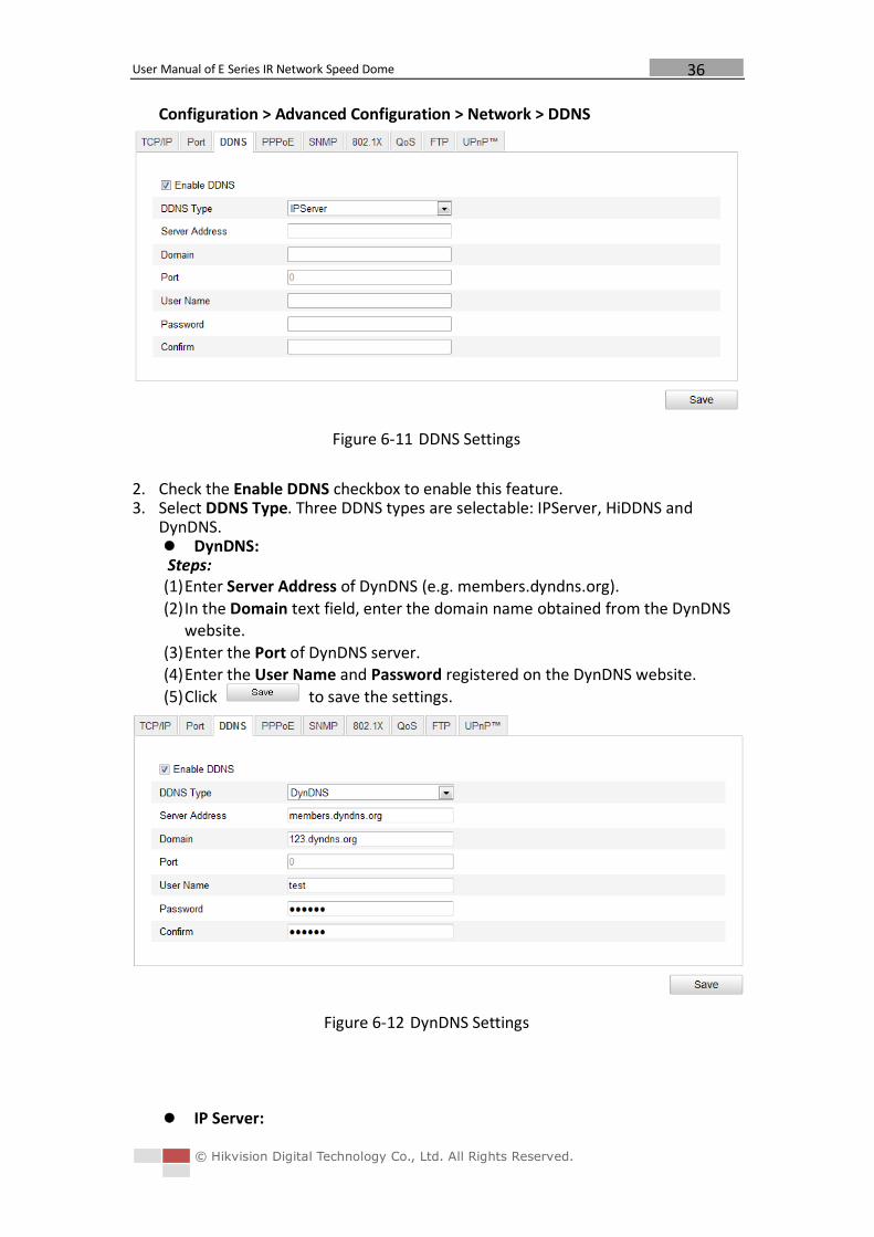
User Manual of E Series IR Network Speed Dome
© Hikvision Digital Technology Co., Ltd. All Rights Reserved.
36
Configuration > Advanced Configuration > Network > DDNS
Figure 6-11 DDNS Settings
2. Check the Enable DDNS checkbox to enable this feature. 3. Select DDNS Type. Three DDNS types are selectable: IPServer, HiDDNS and
DynDNS. DynDNS: Steps: (1) Enter Server Address of DynDNS (e.g. members.dyndns.org).
(2) In the Domain text field, enter the domain name obtained from the DynDNS website.
(3) Enter the Port of DynDNS server. (4) Enter the User Name and Password registered on the DynDNS website.
(5) Click to save the settings.
Figure 6-12 DynDNS Settings
IP Server:
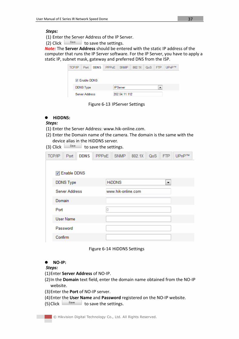
User Manual of E Series IR Network Speed Dome
© Hikvision Digital Technology Co., Ltd. All Rights Reserved.
37
Steps: (1) Enter the Server Address of the IP Server.
(2) Click to save the settings. Note: The Server Address should be entered with the static IP address of the computer that runs the IP Server software. For the IP Server, you have to apply a static IP, subnet mask, gateway and preferred DNS from the ISP.
Figure 6-13 IPServer Settings
HiDDNS: Steps: (1) Enter the Server Address: www.hik-online.com.
(2) Enter the Domain name of the camera. The domain is the same with the device alias in the HiDDNS server.
(3) Click to save the settings.
Figure 6-14 HiDDNS Settings
NO-IP: Steps: (1) Enter Server Address of NO-IP.
(2) In the Domain text field, enter the domain name obtained from the NO-IP website.
(3) Enter the Port of NO-IP server. (4) Enter the User Name and Password registered on the NO-IP website.
(5) Click to save the settings.
User Manual of E Series IR Network Speed Dome
© Hikvision Digital Technology Co., Ltd. All Rights Reserved.
38
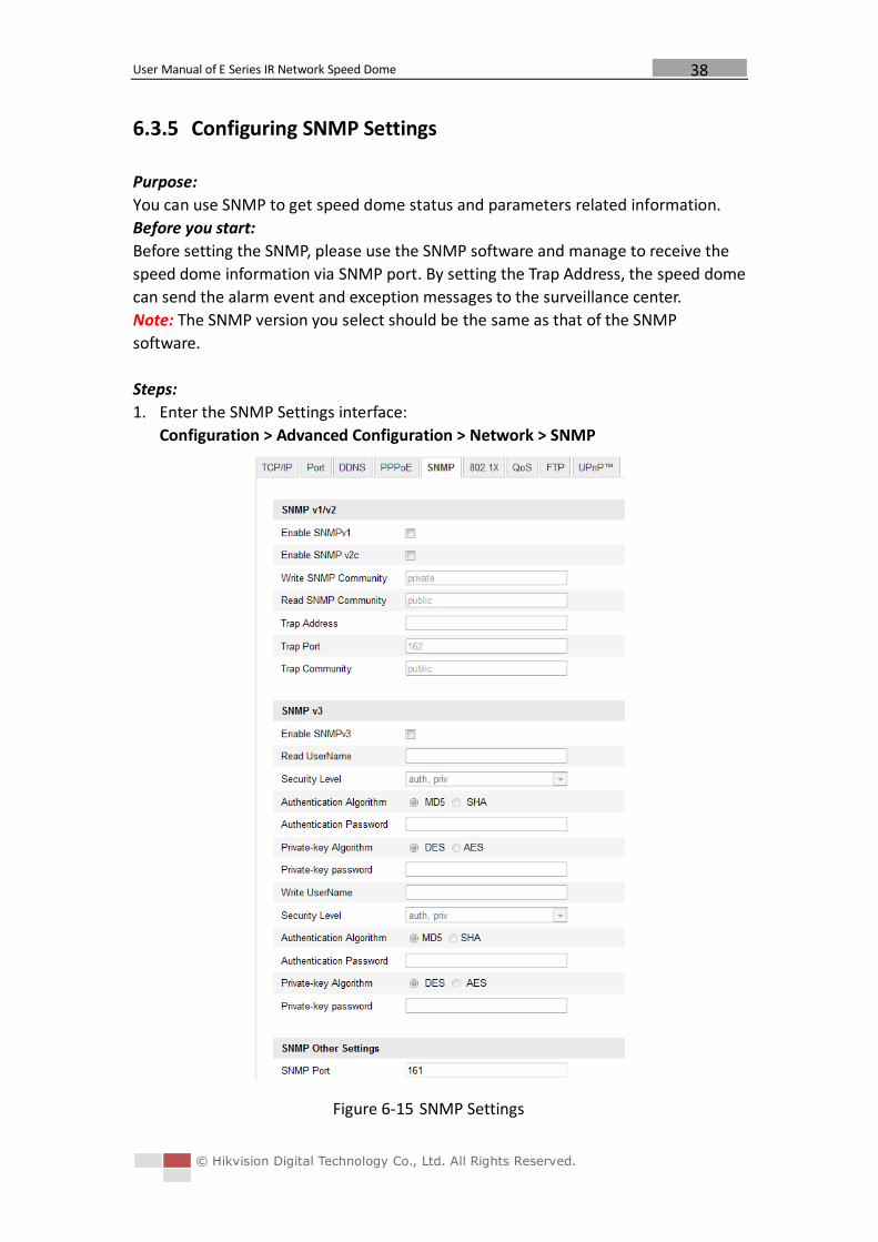
6.3.5 Configuring SNMP Settings
Purpose:
You can use SNMP to get speed dome status and parameters related information.
Before you start:
Before setting the SNMP, please use the SNMP software and manage to receive the
speed dome information via SNMP port. By setting the Trap Address, the speed dome
can send the alarm event and exception messages to the surveillance center.
Note: The SNMP version you select should be the same as that of the SNMP
software.
Steps:
1. Enter the SNMP Settings interface:
Configuration > Advanced Configuration > Network > SNMP
Figure 6-15 SNMP Settings
User Manual of E Series IR Network Speed Dome
© Hikvision Digital Technology Co., Ltd. All Rights Reserved.
39
2. Check the corresponding version checkbox ( ,
, ) to enable the feature.
3. Configure the SNMP settings.
Note: The configuration of the SNMP software should be the same as the settings
you configure here.
4. Click to save and finish the settings.
6.3.6 Configuring 802.1X Settings
Purpose:
The speed dome supports IEEE 802.1X standard.
IEEE 802.1X is a port-based network access control. It enhances the security level of
the LAN. When devices connect to this network with IEEE 802.1X standard, the
authentication is needed. If the authentication fails, the devices don’t connect to the
network.
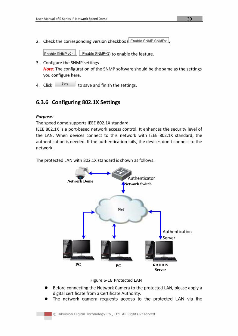
The protected LAN with 802.1X standard is shown as follows:
Network Switch
PC PC RADIUS
Server
Network Dome
Net
Figure 6-16 Protected LAN
Before connecting the Network Camera to the protected LAN, please apply a digital certificate from a Certificate Authority.
The network camera requests access to the protected LAN via the
Authenticator
Authentication
Server
User Manual of E Series IR Network Speed Dome
© Hikvision Digital Technology Co., Ltd. All Rights Reserved.
40
authenticator (a switch). The switch forwards the identity and password to the authentication
server(RADIUS server). The switch forwards the certificate of authentication server to the network
camera. If all the information is validated, the switch allows the network access to
the protected network.
Steps:
1. Connect the network camera to your PC directly with a network cable.
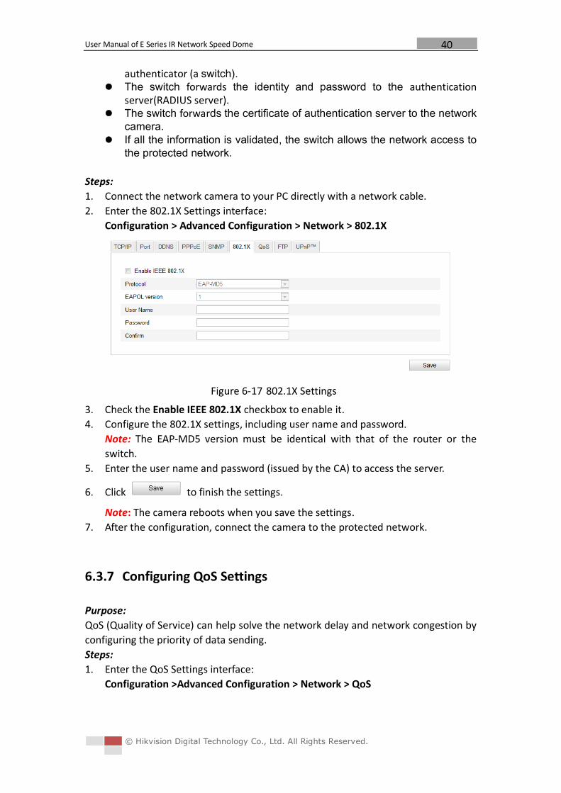
2. Enter the 802.1X Settings interface:
Configuration > Advanced Configuration > Network > 802.1X
Figure 6-17 802.1X Settings
3. Check the Enable IEEE 802.1X checkbox to enable it.
4. Configure the 802.1X settings, including user name and password.
Note: The EAP-MD5 version must be identical with that of the router or the
switch.
5. Enter the user name and password (issued by the CA) to access the server.
6. Click to finish the settings.
Note: The camera reboots when you save the settings.
7. After the configuration, connect the camera to the protected network.
6.3.7 Configuring QoS Settings
Purpose:
QoS (Quality of Service) can help solve the network delay and network congestion by
configuring the priority of data sending.
Steps:
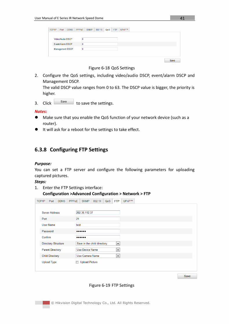
1. Enter the QoS Settings interface:
Configuration >Advanced Configuration > Network > QoS
User Manual of E Series IR Network Speed Dome
© Hikvision Digital Technology Co., Ltd. All Rights Reserved.
41
Figure 6-18 QoS Settings
2. Configure the QoS settings, including video/audio DSCP, event/alarm DSCP and
Management DSCP.
The valid DSCP value ranges from 0 to 63. The DSCP value is bigger, the priority is
higher.
3. Click to save the settings.
Notes:
Make sure that you enable the QoS function of your network device (such as a
router).
It will ask for a reboot for the settings to take effect.
6.3.8 Configuring FTP Settings
Purpose:
You can set a FTP server and configure the following parameters for uploading
captured pictures.
Steps:
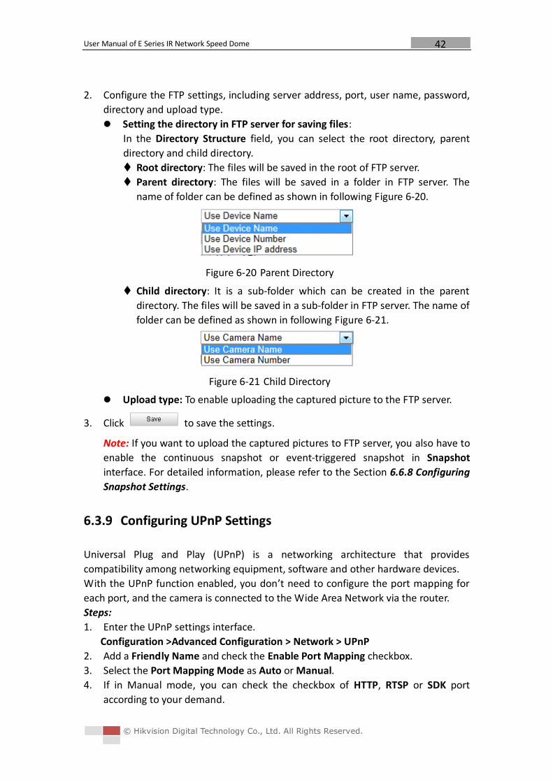
1. Enter the FTP Settings interface:
Configuration >Advanced Configuration > Network > FTP
Figure 6-19 FTP Settings
User Manual of E Series IR Network Speed Dome
© Hikvision Digital Technology Co., Ltd. All Rights Reserved.
42
2. Configure the FTP settings, including server address, port, user name, password,
directory and upload type.
Setting the directory in FTP server for saving files:
In the Directory Structure field, you can select the root directory, parent
directory and child directory.
Root directory: The files will be saved in the root of FTP server.
Parent directory: The files will be saved in a folder in FTP server. The
name of folder can be defined as shown in following Figure 6-20.
Figure 6-20 Parent Directory
Child directory: It is a sub-folder which can be created in the parent
directory. The files will be saved in a sub-folder in FTP server. The name of
folder can be defined as shown in following Figure 6-21.
Figure 6-21 Child Directory
Upload type: To enable uploading the captured picture to the FTP server.
3. Click to save the settings.
Note: If you want to upload the captured pictures to FTP server, you also have to
enable the continuous snapshot or event-triggered snapshot in Snapshot
interface. For detailed information, please refer to the Section 6.6.8 Configuring
Snapshot Settings.
6.3.9 Configuring UPnP Settings
Universal Plug and Play (UPnP) is a networking architecture that provides
compatibility among networking equipment, software and other hardware devices.
With the UPnP function enabled, you don’t need to configure the port mapping for
each port, and the camera is connected to the Wide Area Network via the router.
Steps:
1. Enter the UPnP settings interface.
Configuration >Advanced Configuration > Network > UPnP
2. Add a Friendly Name and check the Enable Port Mapping checkbox.
3. Select the Port Mapping Mode as Auto or Manual.
4. If in Manual mode, you can check the checkbox of HTTP, RTSP or SDK port
according to your demand.
User Manual of E Series IR Network Speed Dome
© Hikvision Digital Technology Co., Ltd. All Rights Reserved.
43
Figure 6-22 Configure UPnP Settings
5. Click to save the settings.
6.4 Configuring Video and Audio Settings
6.4.1 Configuring Video Settings
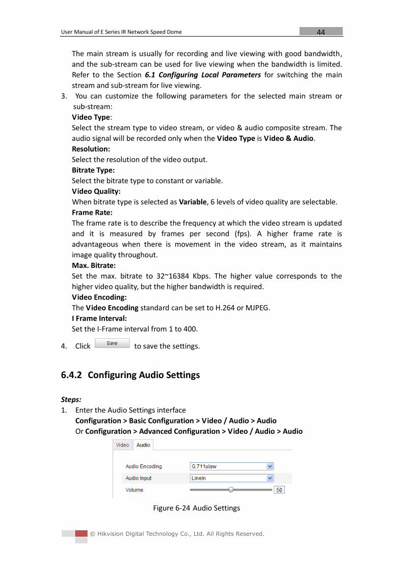
Steps:
1. Enter the Video Settings interface:
Configuration >Basic Configuration > Video / Audio > Video
Or Configuration > Advanced Configuration > Video / Audio > Video
Figure 6-23 Configure Video Settings
2. Select the Stream Type of the speed dome to main stream (normal), sub-stream
or third stream.
User Manual of E Series IR Network Speed Dome
© Hikvision Digital Technology Co., Ltd. All Rights Reserved.
44
The main stream is usually for recording and live viewing with good bandwidth,
and the sub-stream can be used for live viewing when the bandwidth is limited.
Refer to the Section 6.1 Configuring Local Parameters for switching the main
stream and sub-stream for live viewing.
3. You can customize the following parameters for the selected main stream or
sub-stream:
Video Type:
Select the stream type to video stream, or video & audio composite stream. The
audio signal will be recorded only when the Video Type is Video & Audio.
Resolution:
Select the resolution of the video output.
Bitrate Type:
Select the bitrate type to constant or variable.
Video Quality:
When bitrate type is selected as Variable, 6 levels of video quality are selectable.
Frame Rate:
The frame rate is to describe the frequency at which the video stream is updated
and it is measured by frames per second (fps). A higher frame rate is
advantageous when there is movement in the video stream, as it maintains
image quality throughout.
Max. Bitrate:
Set the max. bitrate to 32~16384 Kbps. The higher value corresponds to the
higher video quality, but the higher bandwidth is required.
Video Encoding:
The Video Encoding standard can be set to H.264 or MJPEG.
I Frame Interval:
Set the I-Frame interval from 1 to 400.
4. Click to save the settings.
6.4.2 Configuring Audio Settings
Steps:
1. Enter the Audio Settings interface
Configuration > Basic Configuration > Video / Audio > Audio
Or Configuration > Advanced Configuration > Video / Audio > Audio
Figure 6-24 Audio Settings
User Manual of E Series IR Network Speed Dome
© Hikvision Digital Technology Co., Ltd. All Rights Reserved.
45
2. Configure the following settings.
Audio Encoding: G.711ulaw, G.711alaw and G.726 selectable.
Audio Input: LineIn and MicIn selectable.
Volume: 1 to 100 adjustable.
3. Click to save the settings.
6.5 Configuring Image Settings
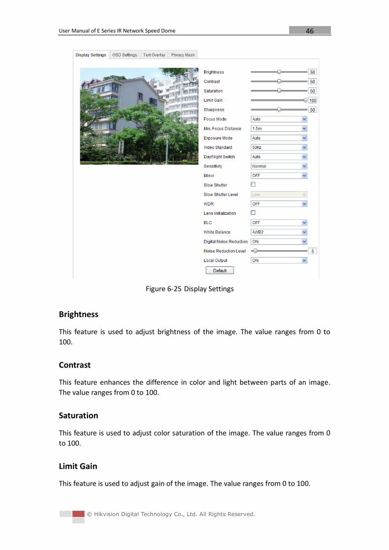
6.5.1 Configuring Display Settings
Purpose:
You can set the image quality of the speed dome, including brightness, contrast,
saturation, sharpness, etc.
Note: The parameters in Display Settings interface vary depending on the models of
speed dome.
Steps:
1. Enter the Display Settings interface:
Configuration > Basic Configuration> Image> Display Settings
Or Configuration > Advanced Configuration> Image> Display Settings
2. Set the image parameters of the speed dome.
User Manual of E Series IR Network Speed Dome
© Hikvision Digital Technology Co., Ltd. All Rights Reserved.
46
Figure 6-25 Display Settings
Brightness
This feature is used to adjust brightness of the image. The value ranges from 0 to
100.
Contrast
This feature enhances the difference in color and light between parts of an image.
The value ranges from 0 to 100.
Saturation
This feature is used to adjust color saturation of the image. The value ranges from 0
to 100.
Limit Gain
This feature is used to adjust gain of the image. The value ranges from 0 to 100.
User Manual of E Series IR Network Speed Dome
© Hikvision Digital Technology Co., Ltd. All Rights Reserved.
47
Sharpness
Sharpness function enhances the detail of the image by sharpening the edges in the
image. The value ranges from 0 to 100.
Note: This function varies depending on the models of speed dome.
Focus Mode
The Focus Mode can be set to Auto, Manual, Semi-auto.
Auto:
The speed dome focuses automatically at any time according to objects in the scene.
Semi-auto:
The speed dome focuses automatically only once after panning, tilting and zooming.
Manual:
In Manual mode, you need to use on the control panel to focus
manually.
Min. Focus Distance
This function is used to limit the minimum focus distance. The value can be set to
1.5m, 3m, 6m, 10cm and 50cm.
Note: The minimum focus value varies depending on the models of speed dome.
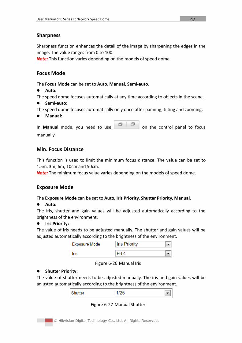
Exposure Mode
The Exposure Mode can be set to Auto, Iris Priority, Shutter Priority, Manual.
Auto:
The iris, shutter and gain values will be adjusted automatically according to the
brightness of the environment.
Iris Priority:
The value of iris needs to be adjusted manually. The shutter and gain values will be
adjusted automatically according to the brightness of the environment.
Figure 6-26 Manual Iris
Shutter Priority:
The value of shutter needs to be adjusted manually. The iris and gain values will be
adjusted automatically according to the brightness of the environment.
Figure 6-27 Manual Shutter
User Manual of E Series IR Network Speed Dome
© Hikvision Digital Technology Co., Ltd. All Rights Reserved.
48
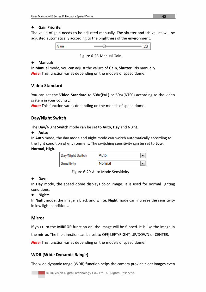
Gain Priority:
The value of gain needs to be adjusted manually. The shutter and iris values will be
adjusted automatically according to the brightness of the environment.
Figure 6-28 Manual Gain
Manual:
In Manual mode, you can adjust the values of Gain, Shutter, Iris manually.
Note: This function varies depending on the models of speed dome.
Video Standard
You can set the Video Standard to 50hz(PAL) or 60hz(NTSC) according to the video
system in your country.
Note: This function varies depending on the models of speed dome.
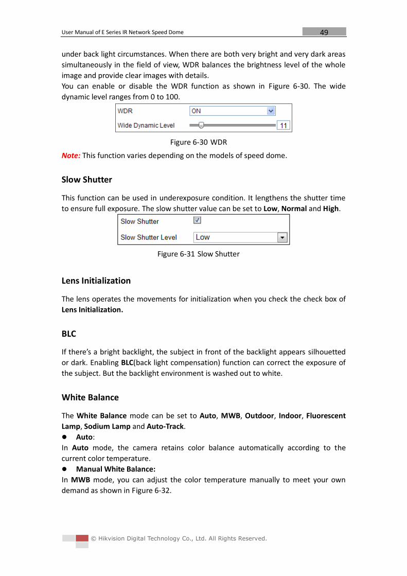
Day/Night Switch
The Day/Night Switch mode can be set to Auto, Day and Night.
Auto:
In Auto mode, the day mode and night mode can switch automatically according to
the light condition of environment. The switching sensitivity can be set to Low,
Normal, High.
Figure 6-29 Auto Mode Sensitivity
Day:
In Day mode, the speed dome displays color image. It is used for normal lighting
conditions.
Night:
In Night mode, the image is black and white. Night mode can increase the sensitivity
in low light conditions.
Mirror
If you turn the MIRROR function on, the image will be flipped. It is like the image in
the mirror. The flip direction can be set to OFF, LEFT/RIGHT, UP/DOWN or CENTER.
Note: This function varies depending on the models of speed dome.
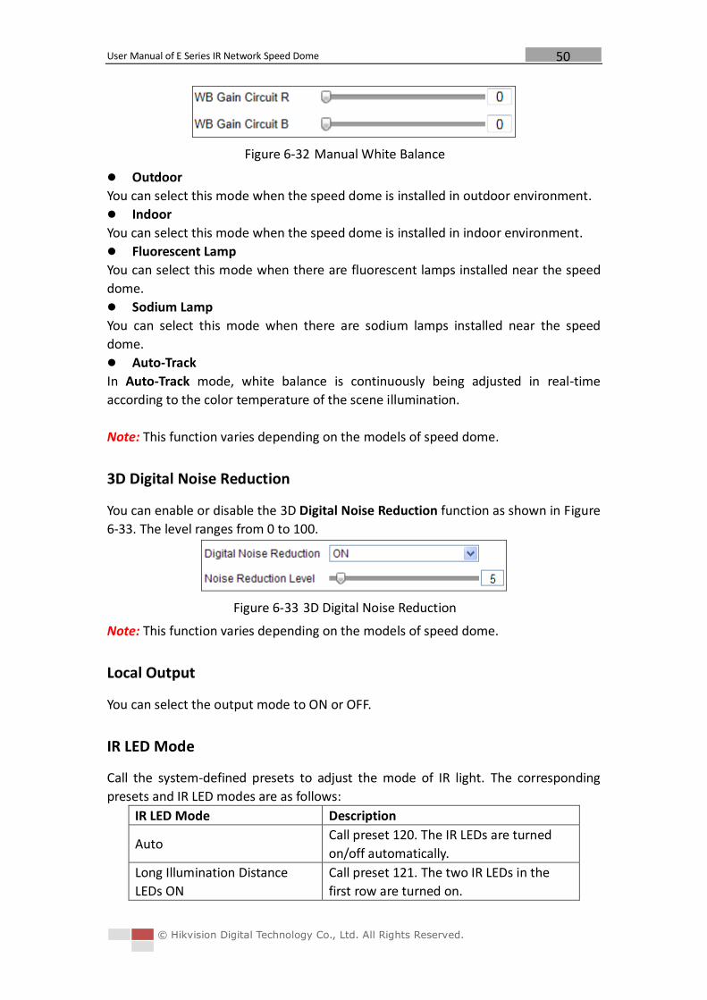
WDR (Wide Dynamic Range)
The wide dynamic range (WDR) function helps the camera provide clear images even
User Manual of E Series IR Network Speed Dome
© Hikvision Digital Technology Co., Ltd. All Rights Reserved.
49
under back light circumstances. When there are both very bright and very dark areas
simultaneously in the field of view, WDR balances the brightness level of the whole
image and provide clear images with details.
You can enable or disable the WDR function as shown in Figure 6-30. The wide
dynamic level ranges from 0 to 100.
Figure 6-30 WDR
Note: This function varies depending on the models of speed dome.
Slow Shutter
This function can be used in underexposure condition. It lengthens the shutter time
to ensure full exposure. The slow shutter value can be set to Low, Normal and High.
Figure 6-31 Slow Shutter
Lens Initialization
The lens operates the movements for initialization when you check the check box of
Lens Initialization.
BLC
If there’s a bright backlight, the subject in front of the backlight appears silhouetted
or dark. Enabling BLC(back light compensation) function can correct the exposure of
the subject. But the backlight environment is washed out to white.
White Balance
The White Balance mode can be set to Auto, MWB, Outdoor, Indoor, Fluorescent
Lamp, Sodium Lamp and Auto-Track.
Auto:
In Auto mode, the camera retains color balance automatically according to the
current color temperature.
Manual White Balance:
In MWB mode, you can adjust the color temperature manually to meet your own
demand as shown in Figure 6-32.
User Manual of E Series IR Network Speed Dome
© Hikvision Digital Technology Co., Ltd. All Rights Reserved.
50
Figure 6-32 Manual White Balance
Outdoor
You can select this mode when the speed dome is installed in outdoor environment.
Indoor
You can select this mode when the speed dome is installed in indoor environment.
Fluorescent Lamp
You can select this mode when there are fluorescent lamps installed near the speed
dome.
Sodium Lamp
You can select this mode when there are sodium lamps installed near the speed
dome.
Auto-Track
In Auto-Track mode, white balance is continuously being adjusted in real-time
according to the color temperature of the scene illumination.
Note: This function varies depending on the models of speed dome.
3D Digital Noise Reduction
You can enable or disable the 3D Digital Noise Reduction function as shown in Figure
6-33. The level ranges from 0 to 100.
Figure 6-33 3D Digital Noise Reduction
Note: This function varies depending on the models of speed dome.
Local Output
You can select the output mode to ON or OFF.
IR LED Mode
Call the system-defined presets to adjust the mode of IR light. The corresponding
presets and IR LED modes are as follows:
IR LED Mode Description
Auto Call preset 120. The IR LEDs are turned
on/off automatically.
Long Illumination Distance
LEDs ON
Call preset 121. The two IR LEDs in the
first row are turned on.
User Manual of E Series IR Network Speed Dome
© Hikvision Digital Technology Co., Ltd. All Rights Reserved.
51
Short Illumination Distance
LEDs ON
Call preset 122. The four IR LEDs in the
second and third rows are turned on.
All LEDs ON Call preset 123. All the IR LEDs are turned
on.
All LEDs OFF Call preset 124. All the IR LEDs are turned
off.
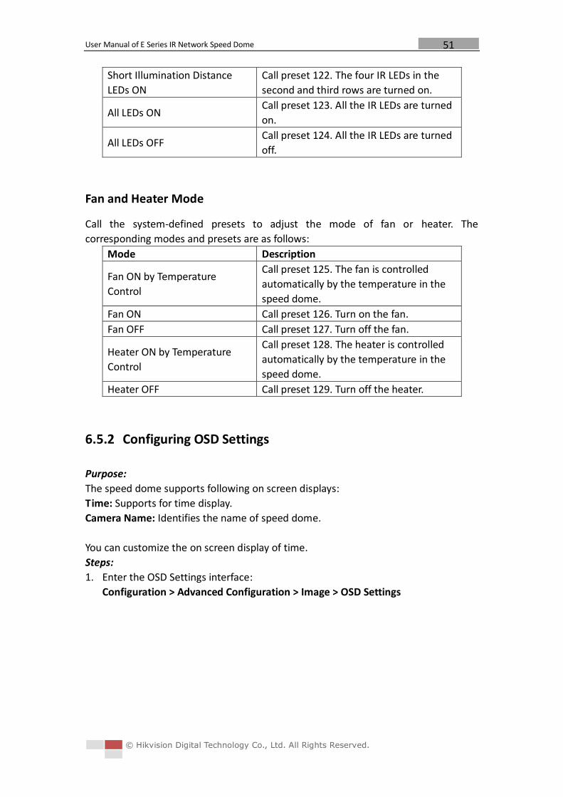
Fan and Heater Mode
Call the system-defined presets to adjust the mode of fan or heater. The
corresponding modes and presets are as follows:
Mode Description
Fan ON by Temperature
Control
Call preset 125. The fan is controlled
automatically by the temperature in the
speed dome.
Fan ON Call preset 126. Turn on the fan.
Fan OFF Call preset 127. Turn off the fan.
Heater ON by Temperature
Control
Call preset 128. The heater is controlled
automatically by the temperature in the
speed dome.
Heater OFF Call preset 129. Turn off the heater.
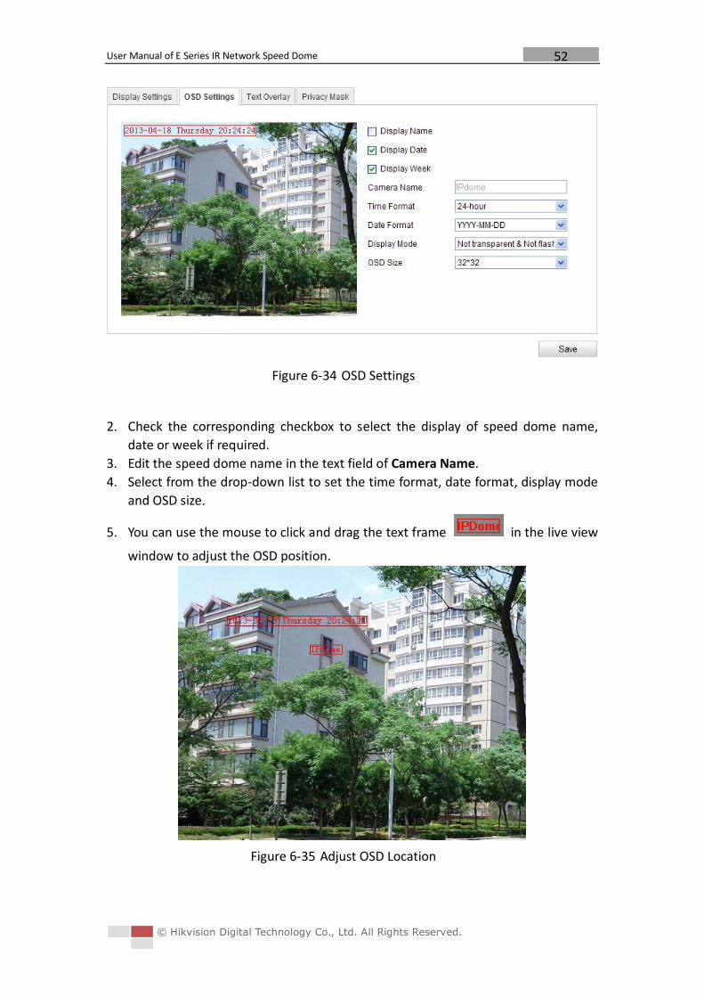
6.5.2 Configuring OSD Settings
Purpose:
The speed dome supports following on screen displays:
Time: Supports for time display.
Camera Name: Identifies the name of speed dome.
You can customize the on screen display of time.
Steps:
1. Enter the OSD Settings interface:
Configuration > Advanced Configuration > Image > OSD Settings
User Manual of E Series IR Network Speed Dome
© Hikvision Digital Technology Co., Ltd. All Rights Reserved.
52
Figure 6-34 OSD Settings
2. Check the corresponding checkbox to select the display of speed dome name,
date or week if required.
3. Edit the speed dome name in the text field of Camera Name.
4. Select from the drop-down list to set the time format, date format, display mode
and OSD size.
5. You can use the mouse to click and drag the text frame in the live view
window to adjust the OSD position.
Figure 6-35 Adjust OSD Location
User Manual of E Series IR Network Speed Dome
© Hikvision Digital Technology Co., Ltd. All Rights Reserved.
53
6. Click to activate above settings.
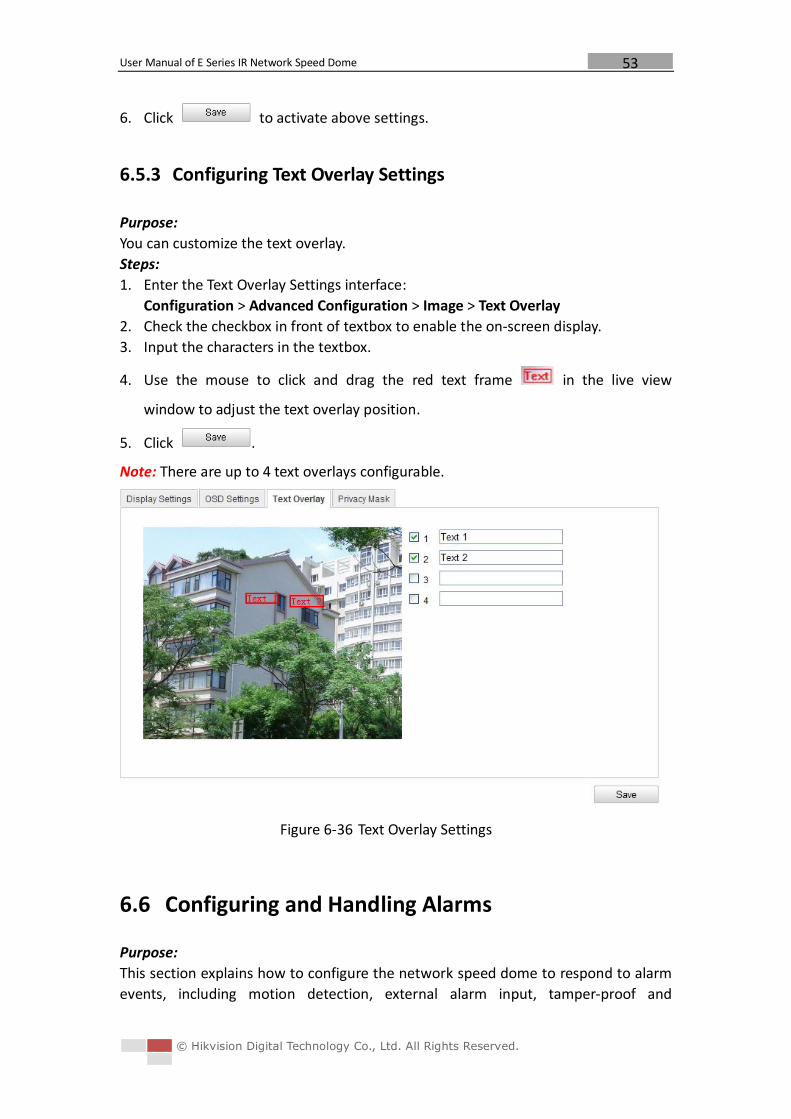
6.5.3 Configuring Text Overlay Settings
Purpose:
You can customize the text overlay.
Steps:
1. Enter the Text Overlay Settings interface:
Configuration > Advanced Configuration > Image > Text Overlay
2. Check the checkbox in front of textbox to enable the on-screen display.
3. Input the characters in the textbox.
4. Use the mouse to click and drag the red text frame in the live view
window to adjust the text overlay position.
5. Click .
Note: There are up to 4 text overlays configurable.
Figure 6-36 Text Overlay Settings
6.6 Configuring and Handling Alarms
Purpose:
This section explains how to configure the network speed dome to respond to alarm
events, including motion detection, external alarm input, tamper-proof and
User Manual of E Series IR Network Speed Dome
© Hikvision Digital Technology Co., Ltd. All Rights Reserved.
54
exception. These events can trigger the alarm actions, such as Notify Surveillance
Center, Send Email, Trigger Alarm Output, etc.
For example, when an external alarm is triggered, the network speed dome sends a
notification to an e-mail address.
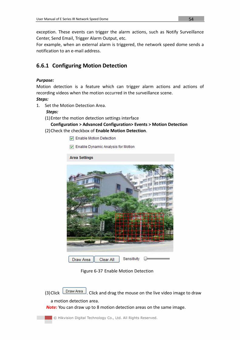
6.6.1 Configuring Motion Detection
Purpose:
Motion detection is a feature which can trigger alarm actions and actions of
recording videos when the motion occurred in the surveillance scene.
Steps:
1. Set the Motion Detection Area.
Steps:
(1) Enter the motion detection settings interface
Configuration > Advanced Configuration> Events > Motion Detection
(2) Check the checkbox of Enable Motion Detection.
Figure 6-37 Enable Motion Detection
(3) Click . Click and drag the mouse on the live video image to draw
a motion detection area.
Note: You can draw up to 8 motion detection areas on the same image.
User Manual of E Series IR Network Speed Dome
© Hikvision Digital Technology Co., Ltd. All Rights Reserved.
55
(4) Click to finish drawing.
Note: You can click to clear all of the areas.
(5) Move the slider to set the sensitivity of the
detection.
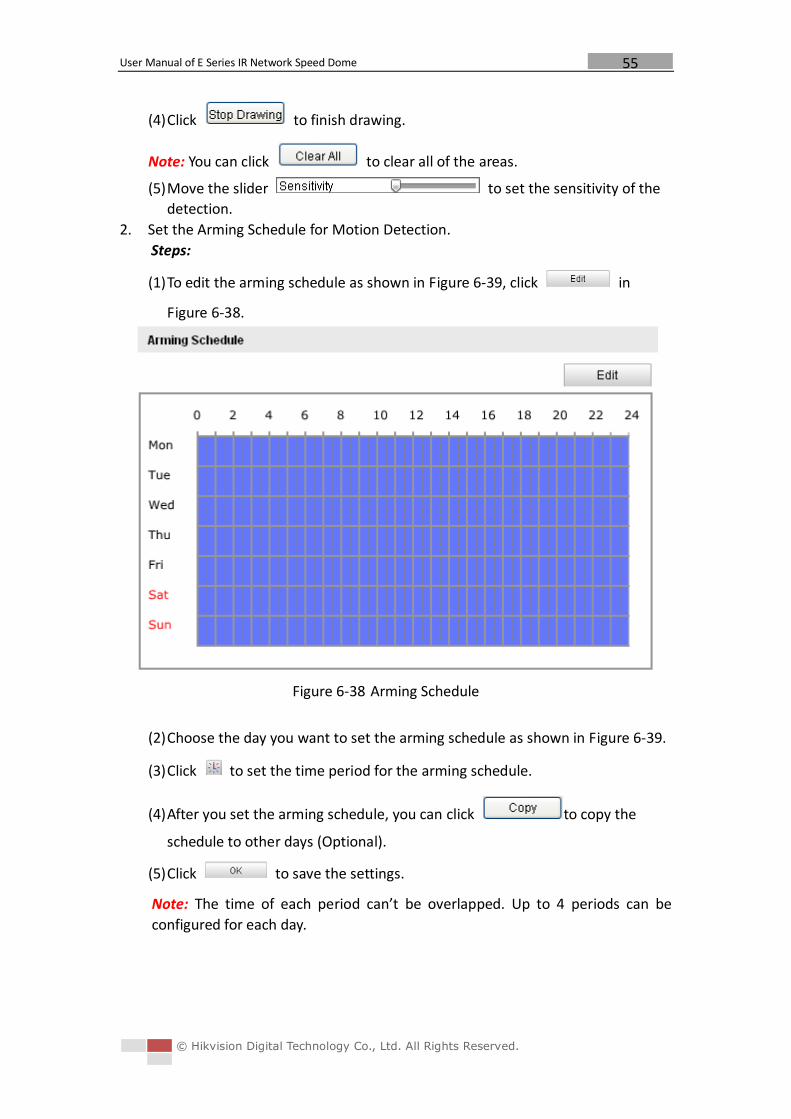
2. Set the Arming Schedule for Motion Detection.
Steps:
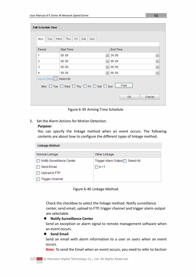
(1) To edit the arming schedule as shown in Figure 6-39, click in
Figure 6-38.
Figure 6-38 Arming Schedule
(2) Choose the day you want to set the arming schedule as shown in Figure 6-39.
(3) Click to set the time period for the arming schedule.
(4) After you set the arming schedule, you can click to copy the
schedule to other days (Optional).
(5) Click to save the settings.
Note: The time of each period can’t be overlapped. Up to 4 periods can be
configured for each day.
User Manual of E Series IR Network Speed Dome
© Hikvision Digital Technology Co., Ltd. All Rights Reserved.
56
Figure 6-39 Arming Time Schedule
3. Set the Alarm Actions for Motion Detection.
Purpose:
You can specify the linkage method when an event occurs. The following
contents are about how to configure the different types of linkage method.
Figure 6-40 Linkage Method
Check the checkbox to select the linkage method. Notify surveillance
center, send email, upload to FTP, trigger channel and trigger alarm output
are selectable.
Notify Surveillance Center
Send an exception or alarm signal to remote management software when
an event occurs.
Send Email
Send an email with alarm information to a user or users when an event
occurs.
Note: To send the Email when an event occurs, you need to refer to Section
User Manual of E Series IR Network Speed Dome
© Hikvision Digital Technology Co., Ltd. All Rights Reserved.
57
6.6.7 Configuring Email Settings to set the Email parameters.
Upload to FTP
Capture the image when an alarm is triggered and upload the picture to a
FTP server.
Note: You need a FTP server and set FTP parameters first. Refer to Section
6.3.8 Configuring FTP Settings for setting FTP parameters.
Trigger Channel
Record a video when an event occurs.
Note: You have to set the recording schedule to realize this function. Please
refer to Section 7.2 Configuring Recording Schedule for settings the
recording schedule.
Trigger Alarm Output
Trigger one or more external alarm outputs when an event occurs.
Note: To trigger an alarm output when an event occurs, please refer to
Section 6.6.5 Configuring Alarm Output to set the alarm output
parameters.
6.6.2 Configuring Tamper-proof Alarm
Purpose:
You can configure the speed dome to trigger the alarm actions when the lens is
covered.
Steps:
1. Enter the Tamper-proof Settings interface:
Configuration > Advanced Configuration > Events > Tamper-proof
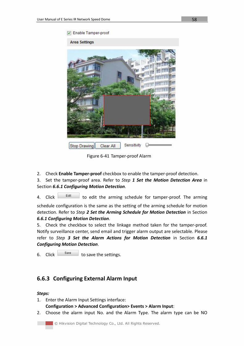
User Manual of E Series IR Network Speed Dome
© Hikvision Digital Technology Co., Ltd. All Rights Reserved.
58
Figure 6-41 Tamper-proof Alarm
2. Check Enable Tamper-proof checkbox to enable the tamper-proof detection.
3. Set the tamper-proof area. Refer to Step 1 Set the Motion Detection Area in
Section 6.6.1 Configuring Motion Detection.
4. Click to edit the arming schedule for tamper-proof. The arming
schedule configuration is the same as the setting of the arming schedule for motion
detection. Refer to Step 2 Set the Arming Schedule for Motion Detection in Section
6.6.1 Configuring Motion Detection.
5. Check the checkbox to select the linkage method taken for the tamper-proof.
Notify surveillance center, send email and trigger alarm output are selectable. Please
refer to Step 3 Set the Alarm Actions for Motion Detection in Section 6.6.1
Configuring Motion Detection.
6. Click to save the settings.
6.6.3 Configuring External Alarm Input
Steps:
1. Enter the Alarm Input Settings interface:
Configuration > Advanced Configuration> Events > Alarm Input:
2. Choose the alarm input No. and the Alarm Type. The alarm type can be NO
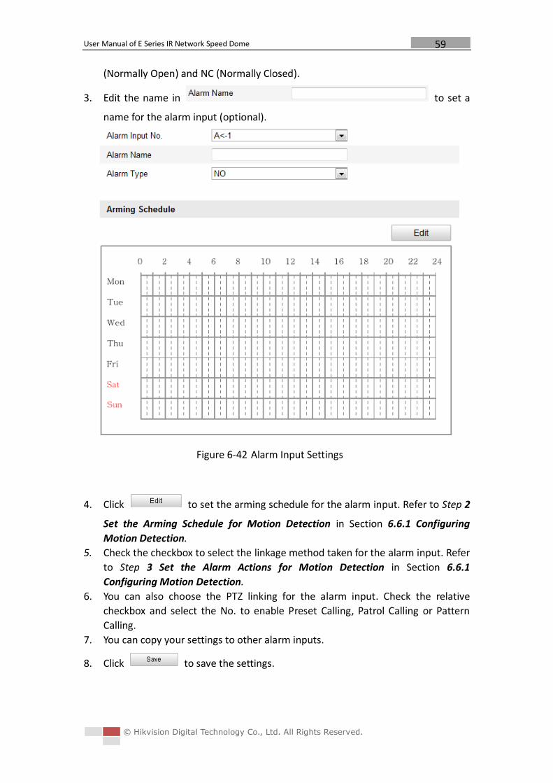
User Manual of E Series IR Network Speed Dome
© Hikvision Digital Technology Co., Ltd. All Rights Reserved.
59
(Normally Open) and NC (Normally Closed).
3. Edit the name in to set a
name for the alarm input (optional).
Figure 6-42 Alarm Input Settings
4. Click to set the arming schedule for the alarm input. Refer to Step 2
Set the Arming Schedule for Motion Detection in Section 6.6.1 Configuring
Motion Detection.
5. Check the checkbox to select the linkage method taken for the alarm input. Refer
to Step 3 Set the Alarm Actions for Motion Detection in Section 6.6.1
Configuring Motion Detection.
6. You can also choose the PTZ linking for the alarm input. Check the relative
checkbox and select the No. to enable Preset Calling, Patrol Calling or Pattern
Calling.
7. You can copy your settings to other alarm inputs.
8. Click to save the settings.
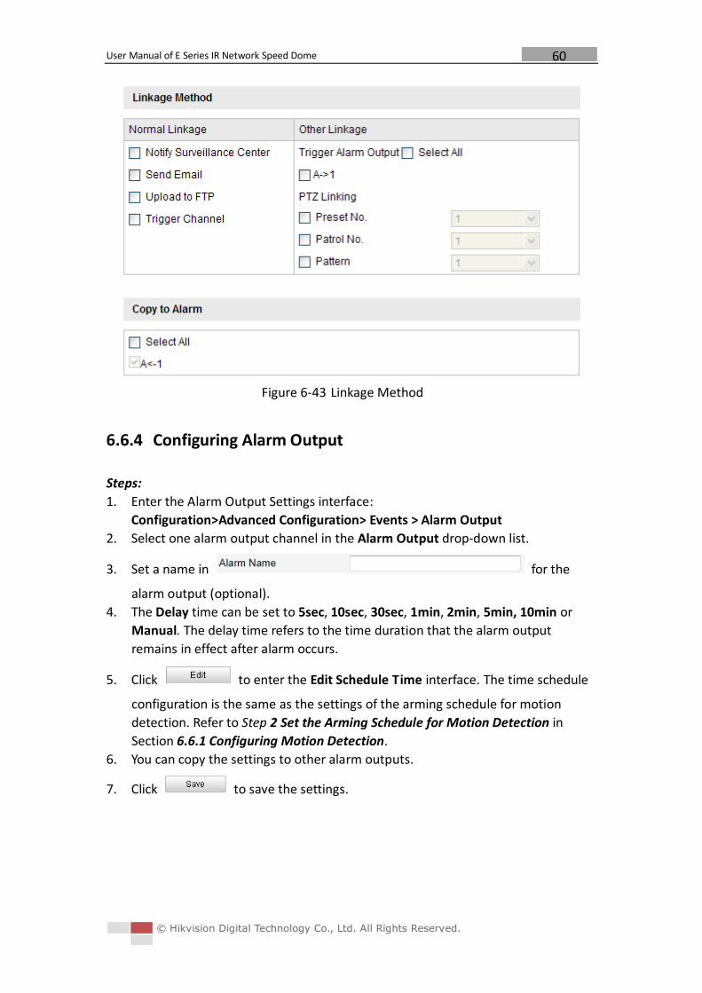
User Manual of E Series IR Network Speed Dome
© Hikvision Digital Technology Co., Ltd. All Rights Reserved.
60
Figure 6-43 Linkage Method
6.6.4 Configuring Alarm Output
Steps:
1. Enter the Alarm Output Settings interface:
Configuration>Advanced Configuration> Events > Alarm Output
2. Select one alarm output channel in the Alarm Output drop-down list.
3. Set a name in for the
alarm output (optional).
4. The Delay time can be set to 5sec, 10sec, 30sec, 1min, 2min, 5min, 10min or
Manual. The delay time refers to the time duration that the alarm output
remains in effect after alarm occurs.
5. Click to enter the Edit Schedule Time interface. The time schedule
configuration is the same as the settings of the arming schedule for motion
detection. Refer to Step 2 Set the Arming Schedule for Motion Detection in
Section 6.6.1 Configuring Motion Detection.
6. You can copy the settings to other alarm outputs.
7. Click to save the settings.
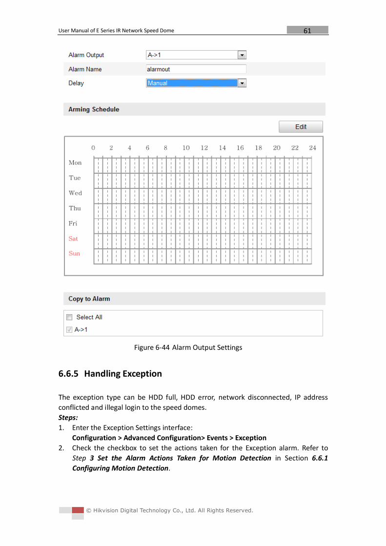
User Manual of E Series IR Network Speed Dome
© Hikvision Digital Technology Co., Ltd. All Rights Reserved.
61
Figure 6-44 Alarm Output Settings
6.6.5 Handling Exception
The exception type can be HDD full, HDD error, network disconnected, IP address
conflicted and illegal login to the speed domes.
Steps:
1. Enter the Exception Settings interface:
Configuration > Advanced Configuration> Events > Exception
2. Check the checkbox to set the actions taken for the Exception alarm. Refer to
Step 3 Set the Alarm Actions Taken for Motion Detection in Section 6.6.1
Configuring Motion Detection.
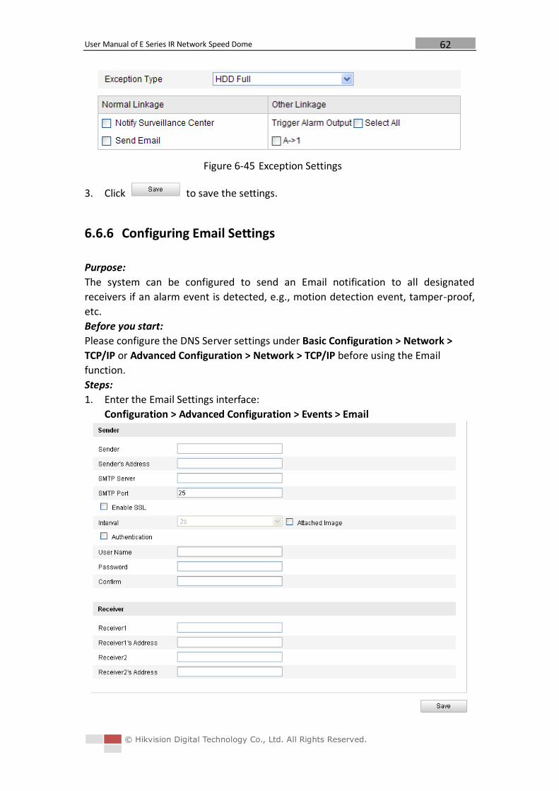
User Manual of E Series IR Network Speed Dome
© Hikvision Digital Technology Co., Ltd. All Rights Reserved.
62
Figure 6-45 Exception Settings
3. Click to save the settings.
6.6.6 Configuring Email Settings
Purpose:
The system can be configured to send an Email notification to all designated
receivers if an alarm event is detected, e.g., motion detection event, tamper-proof,
etc.
Before you start:
Please configure the DNS Server settings under Basic Configuration > Network >
TCP/IP or Advanced Configuration > Network > TCP/IP before using the Email
function.
Steps:
1. Enter the Email Settings interface:
Configuration > Advanced Configuration > Events > Email
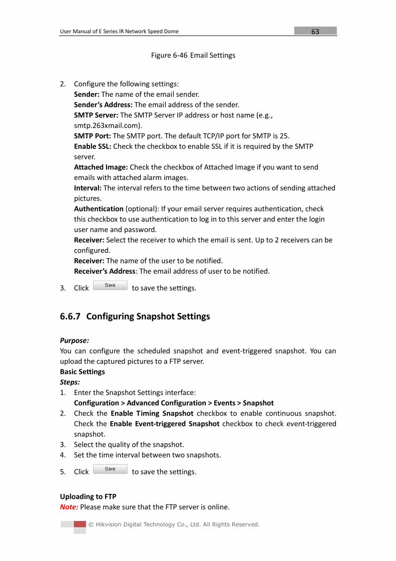
User Manual of E Series IR Network Speed Dome
© Hikvision Digital Technology Co., Ltd. All Rights Reserved.
63
Figure 6-46 Email Settings
2. Configure the following settings:
Sender: The name of the email sender.
Sender’s Address: The email address of the sender.
SMTP Server: The SMTP Server IP address or host name (e.g.,
smtp.263xmail.com).
SMTP Port: The SMTP port. The default TCP/IP port for SMTP is 25.
Enable SSL: Check the checkbox to enable SSL if it is required by the SMTP
server.
Attached Image: Check the checkbox of Attached Image if you want to send
emails with attached alarm images.
Interval: The interval refers to the time between two actions of sending attached
pictures.
Authentication (optional): If your email server requires authentication, check
this checkbox to use authentication to log in to this server and enter the login
user name and password.
Receiver: Select the receiver to which the email is sent. Up to 2 receivers can be
configured.
Receiver: The name of the user to be notified.
Receiver’s Address: The email address of user to be notified.
3. Click to save the settings.
6.6.7 Configuring Snapshot Settings
Purpose:
You can configure the scheduled snapshot and event-triggered snapshot. You can
upload the captured pictures to a FTP server.
Basic Settings
Steps:
1. Enter the Snapshot Settings interface:
Configuration > Advanced Configuration > Events > Snapshot
2. Check the Enable Timing Snapshot checkbox to enable continuous snapshot.
Check the Enable Event-triggered Snapshot checkbox to check event-triggered
snapshot.
3. Select the quality of the snapshot.
4. Set the time interval between two snapshots.
5. Click to save the settings.
Uploading to FTP
Note: Please make sure that the FTP server is online.
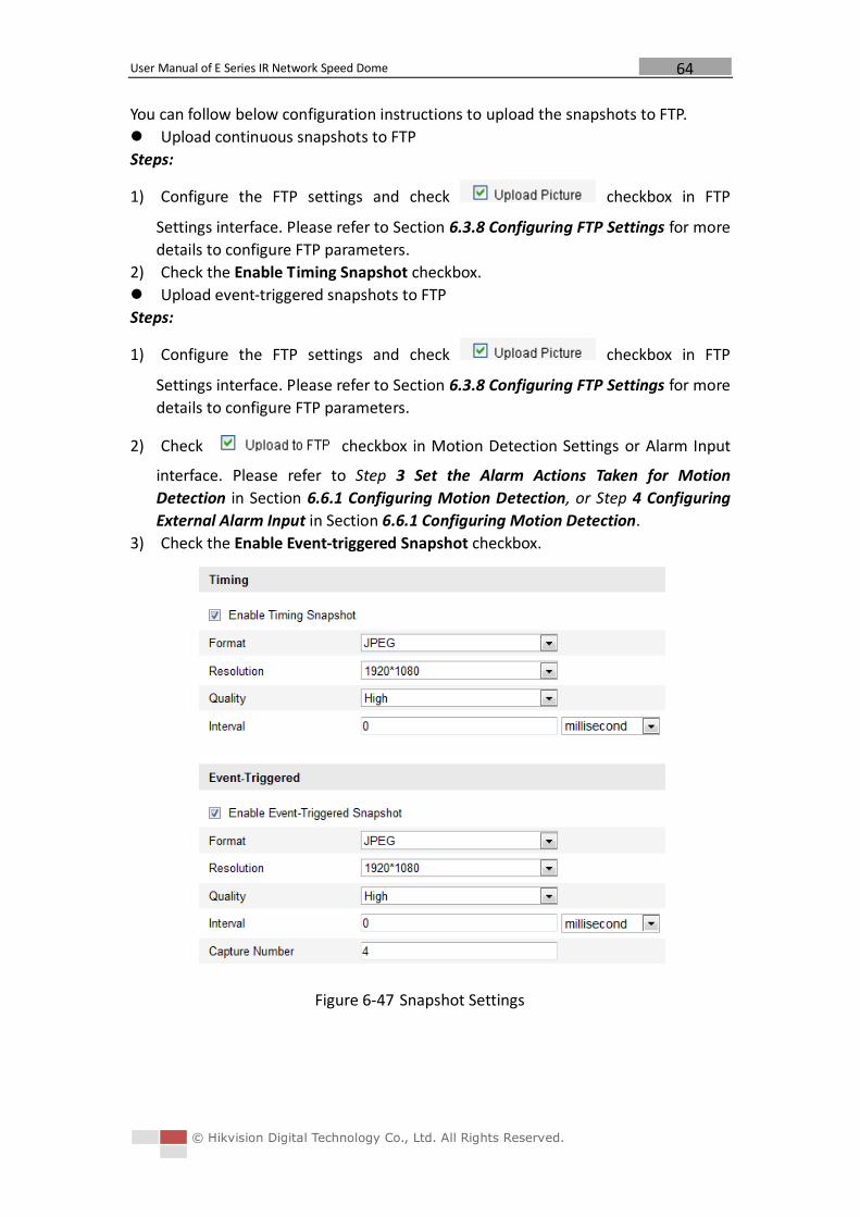
User Manual of E Series IR Network Speed Dome
© Hikvision Digital Technology Co., Ltd. All Rights Reserved.
64
You can follow below configuration instructions to upload the snapshots to FTP.
Upload continuous snapshots to FTP
Steps:
1) Configure the FTP settings and check checkbox in FTP
Settings interface. Please refer to Section 6.3.8 Configuring FTP Settings for more
details to configure FTP parameters.
2) Check the Enable Timing Snapshot checkbox.
Upload event-triggered snapshots to FTP
Steps:
1) Configure the FTP settings and check checkbox in FTP
Settings interface. Please refer to Section 6.3.8 Configuring FTP Settings for more
details to configure FTP parameters.
2) Check checkbox in Motion Detection Settings or Alarm Input
interface. Please refer to Step 3 Set the Alarm Actions Taken for Motion
Detection in Section 6.6.1 Configuring Motion Detection, or Step 4 Configuring
External Alarm Input in Section 6.6.1 Configuring Motion Detection.
3) Check the Enable Event-triggered Snapshot checkbox.
Figure 6-47 Snapshot Settings
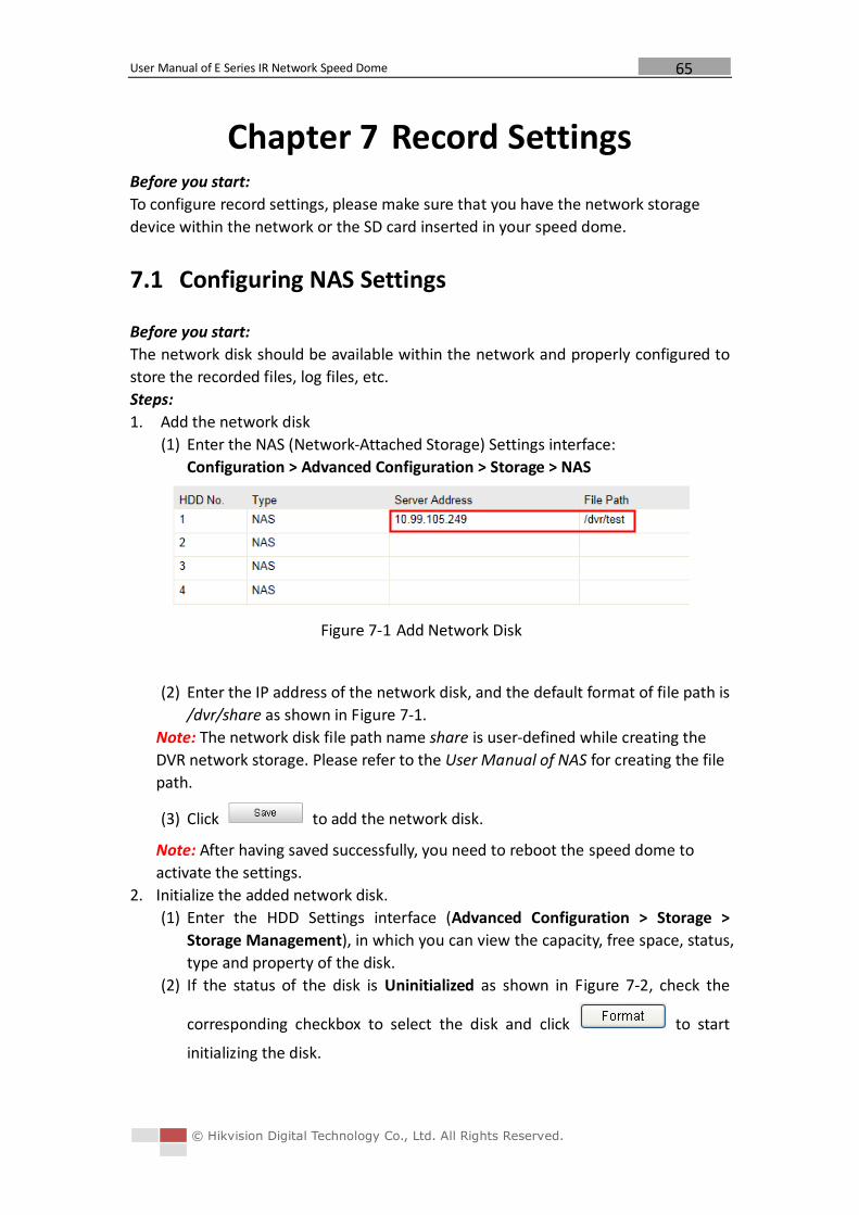
User Manual of E Series IR Network Speed Dome
© Hikvision Digital Technology Co., Ltd. All Rights Reserved.
65
Chapter 7 Record Settings Before you start:
To configure record settings, please make sure that you have the network storage
device within the network or the SD card inserted in your speed dome.
7.1 Configuring NAS Settings
Before you start:
The network disk should be available within the network and properly configured to
store the recorded files, log files, etc.
Steps:
1. Add the network disk
(1) Enter the NAS (Network-Attached Storage) Settings interface:
Configuration > Advanced Configuration > Storage > NAS
Figure 7-1 Add Network Disk
(2) Enter the IP address of the network disk, and the default format of file path is
/dvr/share as shown in Figure 7-1.
Note: The network disk file path name share is user-defined while creating the
DVR network storage. Please refer to the User Manual of NAS for creating the file
path.
(3) Click to add the network disk.
Note: After having saved successfully, you need to reboot the speed dome to
activate the settings.
2. Initialize the added network disk.
(1) Enter the HDD Settings interface (Advanced Configuration > Storage >
Storage Management), in which you can view the capacity, free space, status,
type and property of the disk.
(2) If the status of the disk is Uninitialized as shown in Figure 7-2, check the
corresponding checkbox to select the disk and click to start
initializing the disk.
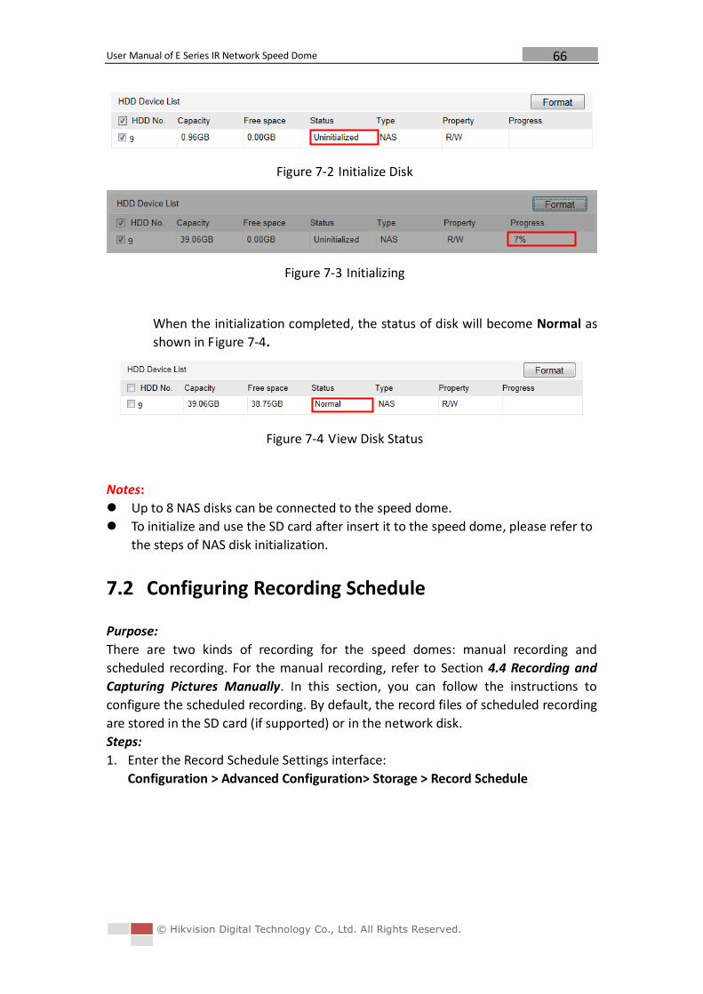
User Manual of E Series IR Network Speed Dome
© Hikvision Digital Technology Co., Ltd. All Rights Reserved.
66
Figure 7-2 Initialize Disk
Figure 7-3 Initializing
When the initialization completed, the status of disk will become Normal as
shown in Figure 7-4.
Figure 7-4 View Disk Status
Notes:
Up to 8 NAS disks can be connected to the speed dome.
To initialize and use the SD card after insert it to the speed dome, please refer to
the steps of NAS disk initialization.
7.2 Configuring Recording Schedule
Purpose:
There are two kinds of recording for the speed domes: manual recording and
scheduled recording. For the manual recording, refer to Section 4.4 Recording and
Capturing Pictures Manually. In this section, you can follow the instructions to
configure the scheduled recording. By default, the record files of scheduled recording
are stored in the SD card (if supported) or in the network disk.
Steps:
1. Enter the Record Schedule Settings interface:
Configuration > Advanced Configuration> Storage > Record Schedule
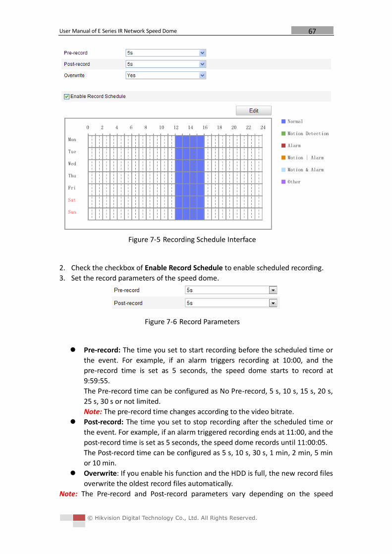
User Manual of E Series IR Network Speed Dome
© Hikvision Digital Technology Co., Ltd. All Rights Reserved.
67
Figure 7-5 Recording Schedule Interface
2. Check the checkbox of Enable Record Schedule to enable scheduled recording.
3. Set the record parameters of the speed dome.
Figure 7-6 Record Parameters
Pre-record: The time you set to start recording before the scheduled time or
the event. For example, if an alarm triggers recording at 10:00, and the
pre-record time is set as 5 seconds, the speed dome starts to record at
9:59:55.
The Pre-record time can be configured as No Pre-record, 5 s, 10 s, 15 s, 20 s,
25 s, 30 s or not limited.
Note: The pre-record time changes according to the video bitrate.
Post-record: The time you set to stop recording after the scheduled time or
the event. For example, if an alarm triggered recording ends at 11:00, and the
post-record time is set as 5 seconds, the speed dome records until 11:00:05.
The Post-record time can be configured as 5 s, 10 s, 30 s, 1 min, 2 min, 5 min
or 10 min.
Overwrite: If you enable his function and the HDD is full, the new record files
overwrite the oldest record files automatically.
Note: The Pre-record and Post-record parameters vary depending on the speed
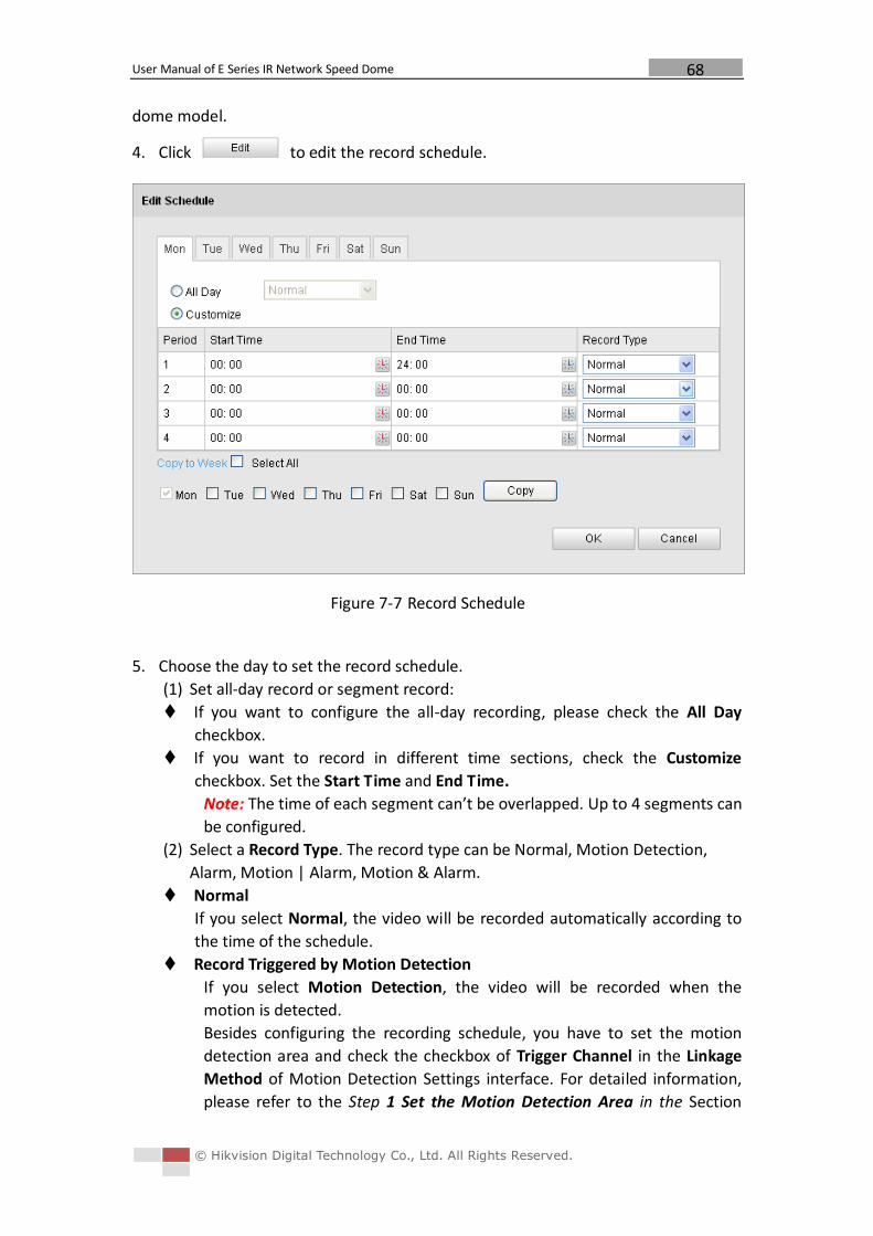
User Manual of E Series IR Network Speed Dome
© Hikvision Digital Technology Co., Ltd. All Rights Reserved.
68
dome model.
4. Click to edit the record schedule.
Figure 7-7 Record Schedule
5. Choose the day to set the record schedule.
(1) Set all-day record or segment record:
If you want to configure the all-day recording, please check the All Day
checkbox.
If you want to record in different time sections, check the Customize
checkbox. Set the Start Time and End Time.
Note: The time of each segment can’t be overlapped. Up to 4 segments can
be configured.
(2) Select a Record Type. The record type can be Normal, Motion Detection,
Alarm, Motion | Alarm, Motion & Alarm.
Normal
If you select Normal, the video will be recorded automatically according to
the time of the schedule.
Record Triggered by Motion Detection
If you select Motion Detection, the video will be recorded when the
motion is detected.
Besides configuring the recording schedule, you have to set the motion
detection area and check the checkbox of Trigger Channel in the Linkage
Method of Motion Detection Settings interface. For detailed information,
please refer to the Step 1 Set the Motion Detection Area in the Section
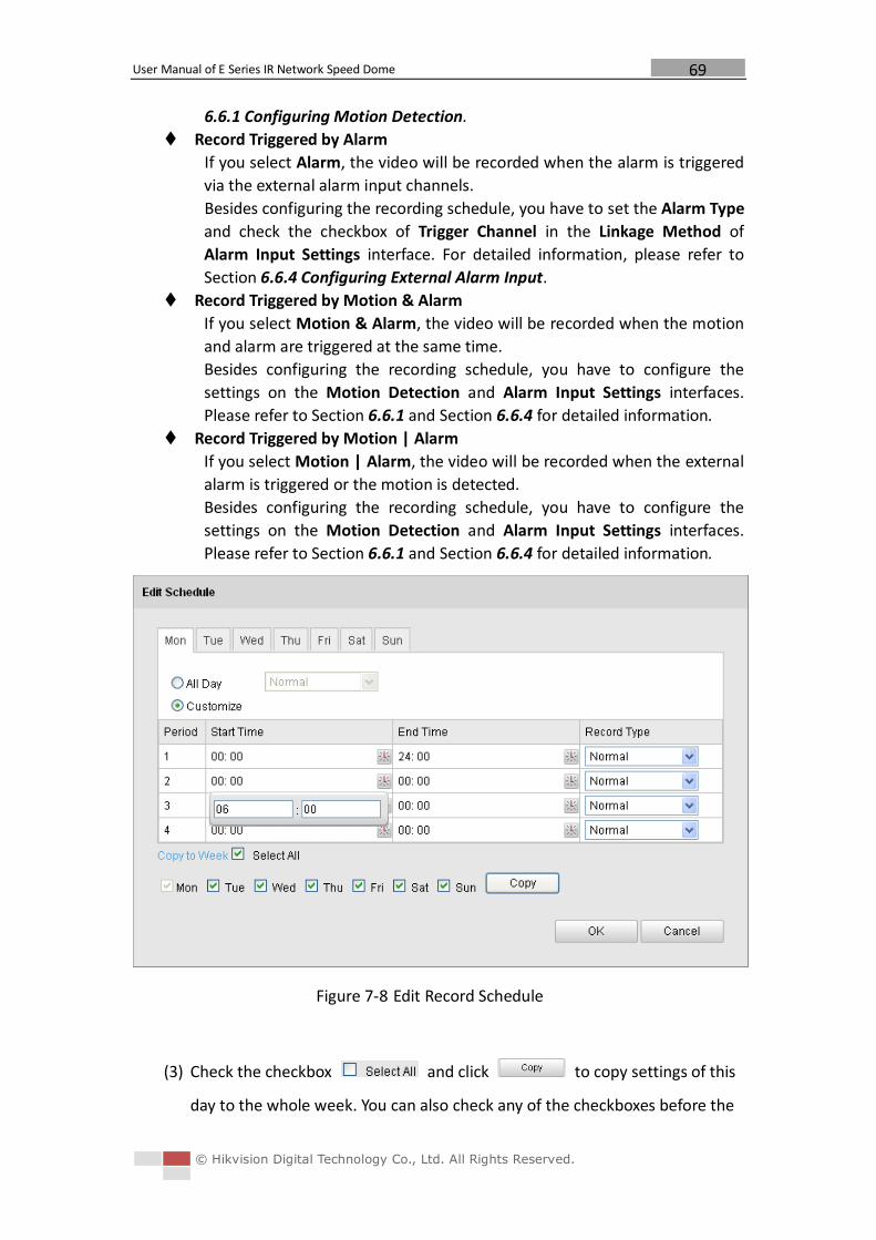
User Manual of E Series IR Network Speed Dome
© Hikvision Digital Technology Co., Ltd. All Rights Reserved.
69
6.6.1 Configuring Motion Detection.
Record Triggered by Alarm
If you select Alarm, the video will be recorded when the alarm is triggered
via the external alarm input channels.
Besides configuring the recording schedule, you have to set the Alarm Type
and check the checkbox of Trigger Channel in the Linkage Method of
Alarm Input Settings interface. For detailed information, please refer to
Section 6.6.4 Configuring External Alarm Input.
Record Triggered by Motion & Alarm
If you select Motion & Alarm, the video will be recorded when the motion
and alarm are triggered at the same time.
Besides configuring the recording schedule, you have to configure the
settings on the Motion Detection and Alarm Input Settings interfaces.
Please refer to Section 6.6.1 and Section 6.6.4 for detailed information.
Record Triggered by Motion | Alarm
If you select Motion | Alarm, the video will be recorded when the external
alarm is triggered or the motion is detected.
Besides configuring the recording schedule, you have to configure the
settings on the Motion Detection and Alarm Input Settings interfaces.
Please refer to Section 6.6.1 and Section 6.6.4 for detailed information.
Figure 7-8 Edit Record Schedule
(3) Check the checkbox and click to copy settings of this
day to the whole week. You can also check any of the checkboxes before the
User Manual of E Series IR Network Speed Dome
© Hikvision Digital Technology Co., Ltd. All Rights Reserved.
70
date and click .
(4) Click to save the settings and exit the Edit Record Schedule
interface.
6. Click to save the settings.
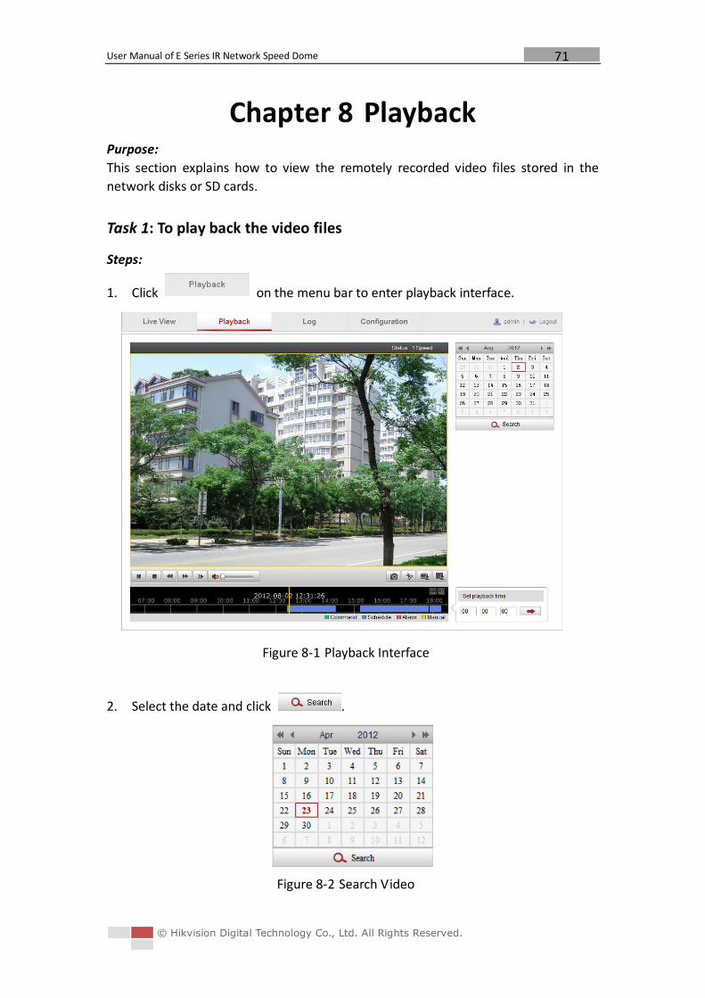
User Manual of E Series IR Network Speed Dome
© Hikvision Digital Technology Co., Ltd. All Rights Reserved.
71
Chapter 8 Playback Purpose:
This section explains how to view the remotely recorded video files stored in the
network disks or SD cards.
Task 1: To play back the video files
Steps:
1. Click on the menu bar to enter playback interface.
Figure 8-1 Playback Interface
2. Select the date and click .
Figure 8-2 Search Video
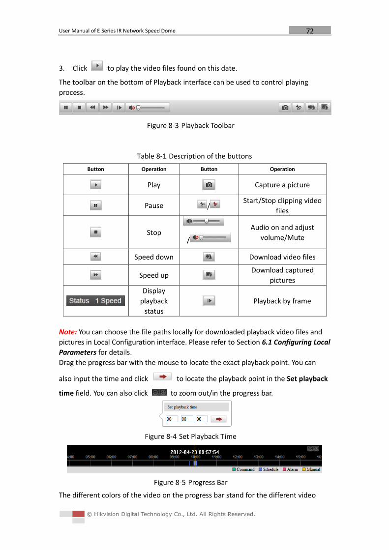
User Manual of E Series IR Network Speed Dome
© Hikvision Digital Technology Co., Ltd. All Rights Reserved.
72
3. Click to play the video files found on this date.
The toolbar on the bottom of Playback interface can be used to control playing
process.
Figure 8-3 Playback Toolbar
Table 8-1 Description of the buttons
Button Operation Button Operation
Play Capture a picture
Pause / Start/Stop clipping video
files
Stop
/
Audio on and adjust
volume/Mute
Speed down Download video files
Speed up Download captured
pictures
Display
playback
status Playback by frame
Note: You can choose the file paths locally for downloaded playback video files and
pictures in Local Configuration interface. Please refer to Section 6.1 Configuring Local
Parameters for details.
Drag the progress bar with the mouse to locate the exact playback point. You can
also input the time and click to locate the playback point in the Set playback
time field. You can also click to zoom out/in the progress bar.
Figure 8-4 Set Playback Time
Figure 8-5 Progress Bar
The different colors of the video on the progress bar stand for the different video
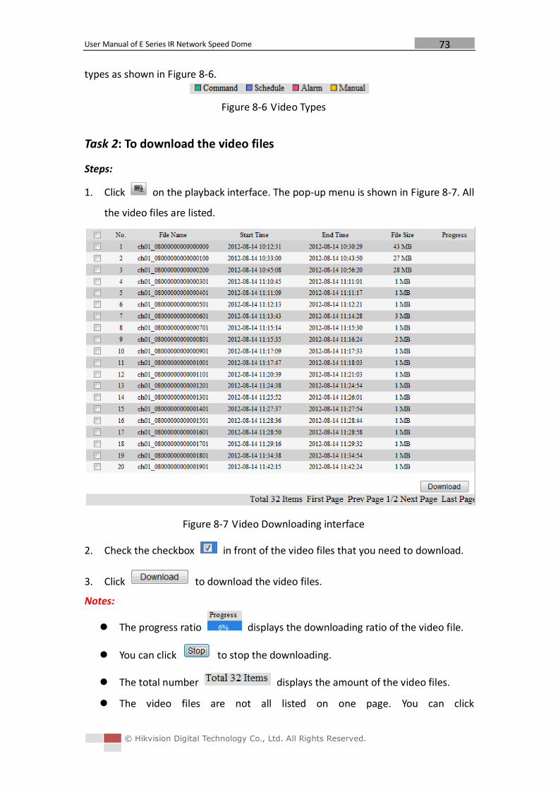
User Manual of E Series IR Network Speed Dome
© Hikvision Digital Technology Co., Ltd. All Rights Reserved.
73
types as shown in Figure 8-6.
Figure 8-6 Video Types
Task 2: To download the video files
Steps:
1. Click on the playback interface. The pop-up menu is shown in Figure 8-7. All
the video files are listed.
Figure 8-7 Video Downloading interface
2. Check the checkbox in front of the video files that you need to download.
3. Click to download the video files.
Notes:
The progress ratio displays the downloading ratio of the video file.
You can click to stop the downloading.
The total number displays the amount of the video files.
The video files are not all listed on one page. You can click
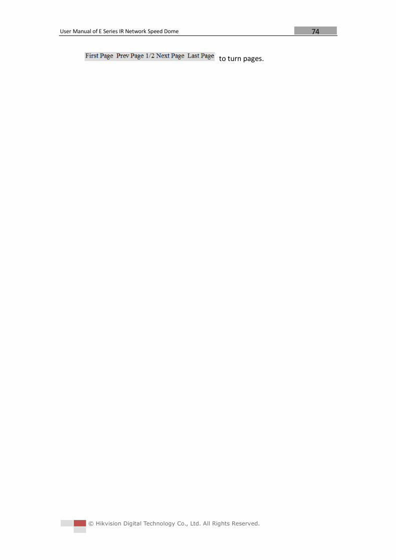
User Manual of E Series IR Network Speed Dome
© Hikvision Digital Technology Co., Ltd. All Rights Reserved.
74
to turn pages.

User Manual of E Series IR Network Speed Dome
© Hikvision Digital Technology Co., Ltd. All Rights Reserved.
75
Chapter 9 Log Searching Purpose:
The operation, alarm, exception and information of the speed dome can be stored in
log files. You can also export the log files on your demand.
Before you start:
Please configure network storage for the speed dome or insert a SD card in the speed
dome.
Steps:
1. Click on the menu bar to enter log searching interface.
Figure 9-1 Log Searching Interface
2. Set the log search conditions to specify the search, including the Major Type,
Minor Type, Start Time and End Time as shown in Figure 9-2.
3. Click to search log files. The matched log files will be displayed on
the Log interface.
Figure 9-2 Log Searching

User Manual of E Series IR Network Speed Dome
© Hikvision Digital Technology Co., Ltd. All Rights Reserved.
76
4. To export the log files, click to save the log files in your computer.
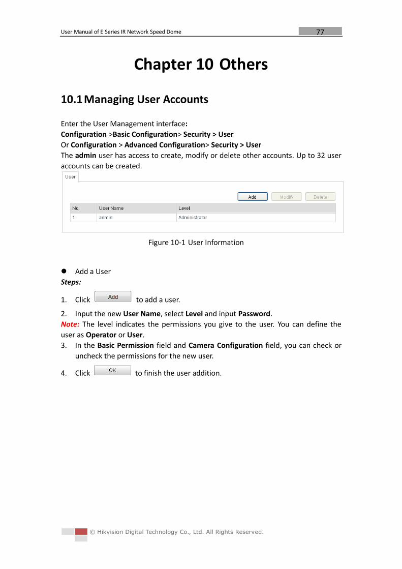
User Manual of E Series IR Network Speed Dome
© Hikvision Digital Technology Co., Ltd. All Rights Reserved.
77
Chapter 10 Others
10.1 Managing User Accounts
Enter the User Management interface:
Configuration >Basic Configuration> Security > User
Or Configuration > Advanced Configuration> Security > User
The admin user has access to create, modify or delete other accounts. Up to 32 user
accounts can be created.
Figure 10-1 User Information
Add a User
Steps:
1. Click to add a user.
2. Input the new User Name, select Level and input Password.
Note: The level indicates the permissions you give to the user. You can define the
user as Operator or User.
3. In the Basic Permission field and Camera Configuration field, you can check or
uncheck the permissions for the new user.
4. Click to finish the user addition.
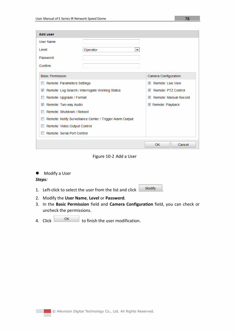
User Manual of E Series IR Network Speed Dome
© Hikvision Digital Technology Co., Ltd. All Rights Reserved.
78
Figure 10-2 Add a User
Modify a User
Steps:
1. Left-click to select the user from the list and click .
2. Modify the User Name, Level or Password.
3. In the Basic Permission field and Camera Configuration field, you can check or
uncheck the permissions.
4. Click to finish the user modification.
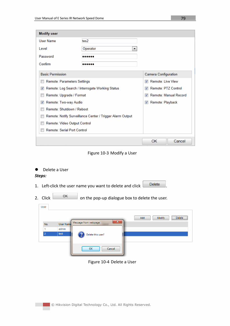
User Manual of E Series IR Network Speed Dome
© Hikvision Digital Technology Co., Ltd. All Rights Reserved.
79
Figure 10-3 Modify a User
Delete a User
Steps:
1. Left-click the user name you want to delete and click .
2. Click on the pop-up dialogue box to delete the user.
Figure 10-4 Delete a User
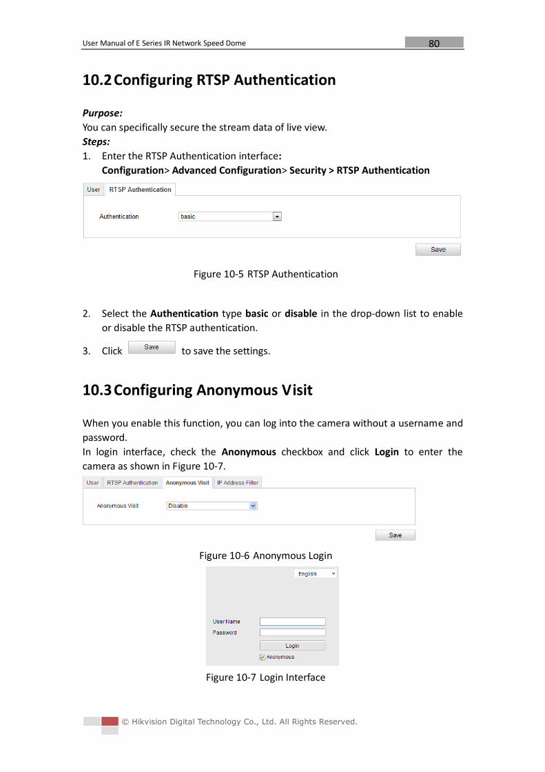
User Manual of E Series IR Network Speed Dome
© Hikvision Digital Technology Co., Ltd. All Rights Reserved.
80
10.2 Configuring RTSP Authentication
Purpose:
You can specifically secure the stream data of live view.
Steps:
1. Enter the RTSP Authentication interface:
Configuration> Advanced Configuration> Security > RTSP Authentication
Figure 10-5 RTSP Authentication
2. Select the Authentication type basic or disable in the drop-down list to enable
or disable the RTSP authentication.
3. Click to save the settings.
10.3 Configuring Anonymous Visit
When you enable this function, you can log into the camera without a username and
password.
In login interface, check the Anonymous checkbox and click Login to enter the
camera as shown in Figure 10-7.
Figure 10-6 Anonymous Login
Figure 10-7 Login Interface
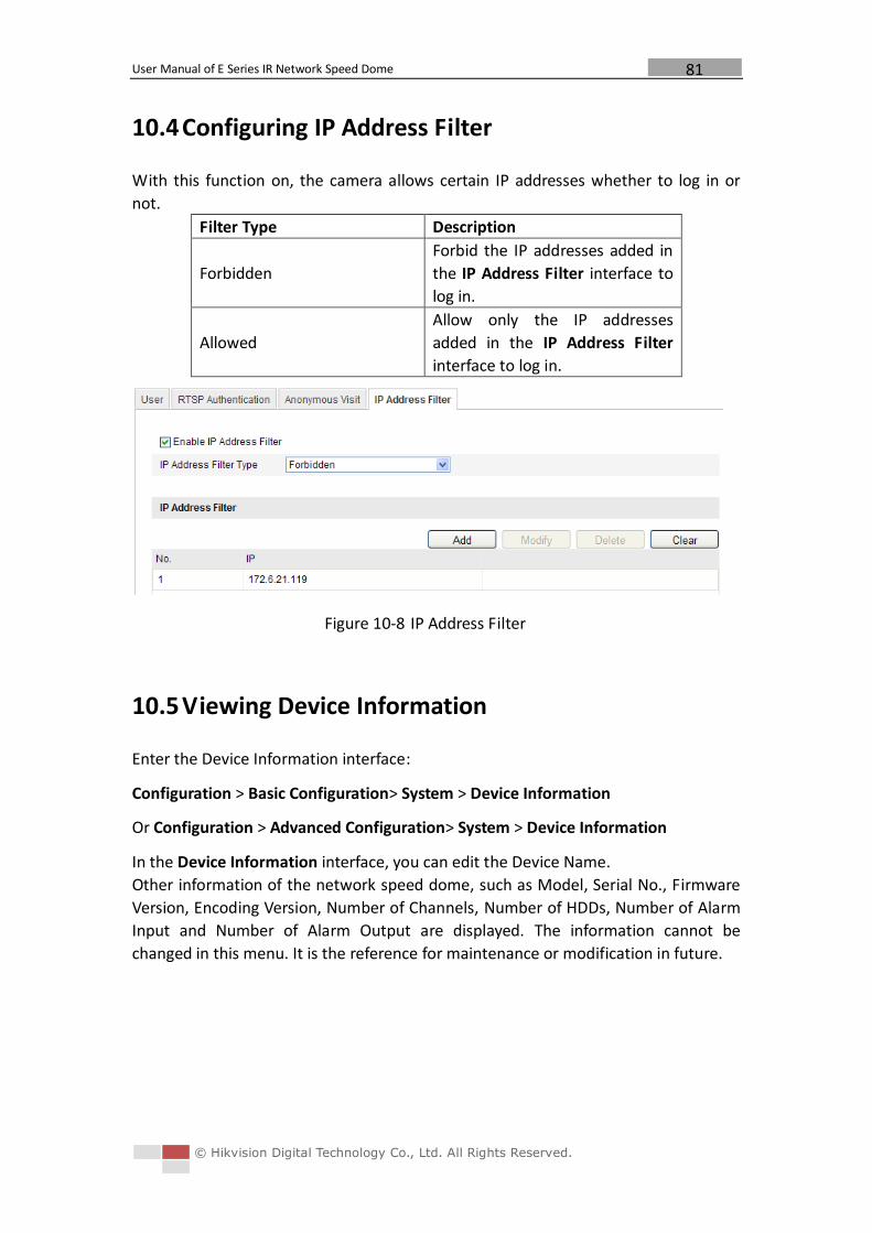
User Manual of E Series IR Network Speed Dome
© Hikvision Digital Technology Co., Ltd. All Rights Reserved.
81
10.4 Configuring IP Address Filter
With this function on, the camera allows certain IP addresses whether to log in or
not.
Filter Type Description
Forbidden
Forbid the IP addresses added in
the IP Address Filter interface to
log in.
Allowed
Allow only the IP addresses
added in the IP Address Filter
interface to log in.
Figure 10-8 IP Address Filter
10.5 Viewing Device Information
Enter the Device Information interface:
Configuration > Basic Configuration> System > Device Information
Or Configuration > Advanced Configuration> System > Device Information
In the Device Information interface, you can edit the Device Name.
Other information of the network speed dome, such as Model, Serial No., Firmware
Version, Encoding Version, Number of Channels, Number of HDDs, Number of Alarm
Input and Number of Alarm Output are displayed. The information cannot be
changed in this menu. It is the reference for maintenance or modification in future.
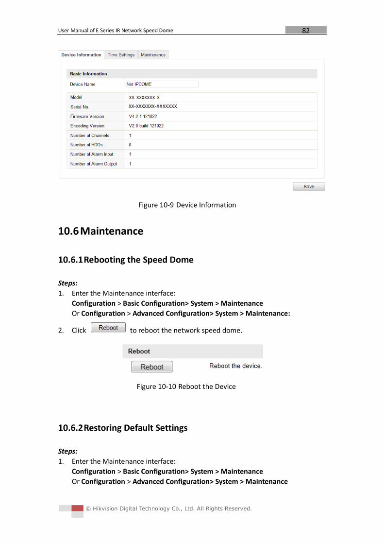
User Manual of E Series IR Network Speed Dome
© Hikvision Digital Technology Co., Ltd. All Rights Reserved.
82
Figure 10-9 Device Information
10.6 Maintenance
10.6.1 Rebooting the Speed Dome
Steps:
1. Enter the Maintenance interface:
Configuration > Basic Configuration> System > Maintenance
Or Configuration > Advanced Configuration> System > Maintenance:
2. Click to reboot the network speed dome.
Figure 10-10 Reboot the Device
10.6.2 Restoring Default Settings
Steps:
1. Enter the Maintenance interface:
Configuration > Basic Configuration> System > Maintenance
Or Configuration > Advanced Configuration> System > Maintenance
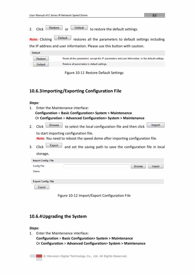
User Manual of E Series IR Network Speed Dome
© Hikvision Digital Technology Co., Ltd. All Rights Reserved.
83
2. Click or to restore the default settings.
Note: Clicking restores all the parameters to default settings including
the IP address and user information. Please use this button with caution.
Figure 10-11 Restore Default Settings
10.6.3 Importing/Exporting Configuration File
Steps:
1. Enter the Maintenance interface:
Configuration > Basic Configuration> System > Maintenance
Or Configuration > Advanced Configuration> System > Maintenance
2. Click to select the local configuration file and then click
to start importing configuration file.
Note: You need to reboot the speed dome after importing configuration file.
3. Click and set the saving path to save the configuration file in local
storage.
Figure 10-12 Import/Export Configuration File
10.6.4 Upgrading the System
Steps:
1. Enter the Maintenance interface:
Configuration > Basic Configuration> System > Maintenance
Or Configuration > Advanced Configuration> System > Maintenance
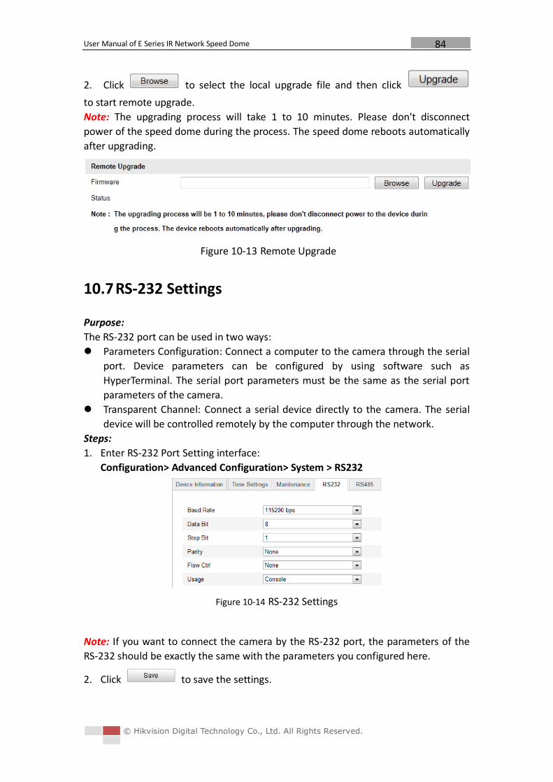
User Manual of E Series IR Network Speed Dome
© Hikvision Digital Technology Co., Ltd. All Rights Reserved.
84
2. Click to select the local upgrade file and then click
to start remote upgrade.
Note: The upgrading process will take 1 to 10 minutes. Please don't disconnect
power of the speed dome during the process. The speed dome reboots automatically
after upgrading.
Figure 10-13 Remote Upgrade
10.7 RS-232 Settings
Purpose:
The RS-232 port can be used in two ways:
Parameters Configuration: Connect a computer to the camera through the serial
port. Device parameters can be configured by using software such as
HyperTerminal. The serial port parameters must be the same as the serial port
parameters of the camera.
Transparent Channel: Connect a serial device directly to the camera. The serial
device will be controlled remotely by the computer through the network.
Steps:
1. Enter RS-232 Port Setting interface:
Configuration> Advanced Configuration> System > RS232
Figure 10-14 RS-232 Settings
Note: If you want to connect the camera by the RS-232 port, the parameters of the
RS-232 should be exactly the same with the parameters you configured here.
2. Click to save the settings.
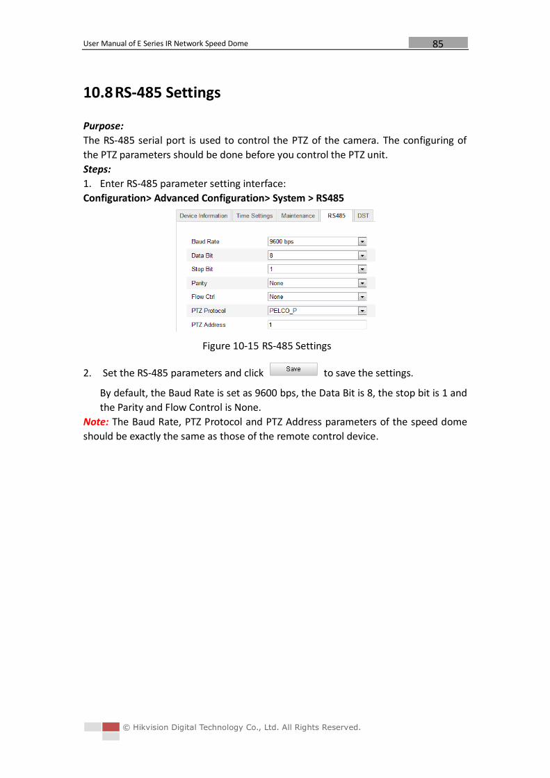
User Manual of E Series IR Network Speed Dome
© Hikvision Digital Technology Co., Ltd. All Rights Reserved.
85
10.8 RS-485 Settings
Purpose:
The RS-485 serial port is used to control the PTZ of the camera. The configuring of
the PTZ parameters should be done before you control the PTZ unit.
Steps:
1. Enter RS-485 parameter setting interface:
Configuration> Advanced Configuration> System > RS485
Figure 10-15 RS-485 Settings
2. Set the RS-485 parameters and click to save the settings.
By default, the Baud Rate is set as 9600 bps, the Data Bit is 8, the stop bit is 1 and
the Parity and Flow Control is None.
Note: The Baud Rate, PTZ Protocol and PTZ Address parameters of the speed dome
should be exactly the same as those of the remote control device.
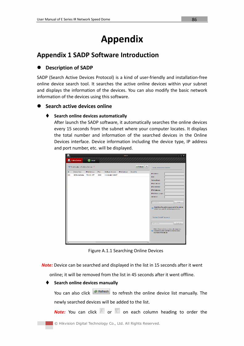
User Manual of E Series IR Network Speed Dome
© Hikvision Digital Technology Co., Ltd. All Rights Reserved.
86
Appendix
Appendix 1 SADP Software Introduction
Description of SADP
SADP (Search Active Devices Protocol) is a kind of user-friendly and installation-free
online device search tool. It searches the active online devices within your subnet
and displays the information of the devices. You can also modify the basic network
information of the devices using this software.
Search active devices online
Search online devices automatically
After launch the SADP software, it automatically searches the online devices
every 15 seconds from the subnet where your computer locates. It displays
the total number and information of the searched devices in the Online
Devices interface. Device information including the device type, IP address
and port number, etc. will be displayed.
Figure A.1.1 Searching Online Devices
Note: Device can be searched and displayed in the list in 15 seconds after it went
online; it will be removed from the list in 45 seconds after it went offline.
Search online devices manually
You can also click to refresh the online device list manually. The
newly searched devices will be added to the list.
Note: You can click or on each column heading to order the
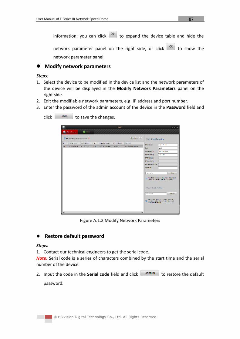
User Manual of E Series IR Network Speed Dome
© Hikvision Digital Technology Co., Ltd. All Rights Reserved.
87
information; you can click to expand the device table and hide the
network parameter panel on the right side, or click to show the
network parameter panel.
Modify network parameters
Steps:
1. Select the device to be modified in the device list and the network parameters of
the device will be displayed in the Modify Network Parameters panel on the
right side.
2. Edit the modifiable network parameters, e.g. IP address and port number.
3. Enter the password of the admin account of the device in the Password field and
click to save the changes.
Figure A.1.2 Modify Network Parameters
Restore default password
Steps:
1. Contact our technical engineers to get the serial code.
Note: Serial code is a series of characters combined by the start time and the serial
number of the device.
2. Input the code in the Serial code field and click to restore the default
password.
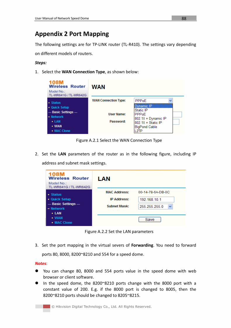
User Manual of Network Speed Dome
© Hikvision Digital Technology Co., Ltd. All Rights Reserved.
88
Appendix 2 Port Mapping
The following settings are for TP-LINK router (TL-R410). The settings vary depending
on different models of routers.
Steps:
1. Select the WAN Connection Type, as shown below:
Figure A.2.1 Select the WAN Connection Type
2. Set the LAN parameters of the router as in the following figure, including IP
address and subnet mask settings.
Figure A.2.2 Set the LAN parameters
3. Set the port mapping in the virtual severs of Forwarding. You need to forward
ports 80, 8000, 8200~8210 and 554 for a speed dome.
Notes:
You can change 80, 8000 and 554 ports value in the speed dome with web
browser or client software.
In the speed dome, the 8200~8210 ports change with the 8000 port with a
constant value of 200. E.g. if the 8000 port is changed to 8005, then the
8200~8210 ports should be changed to 8205~8215.
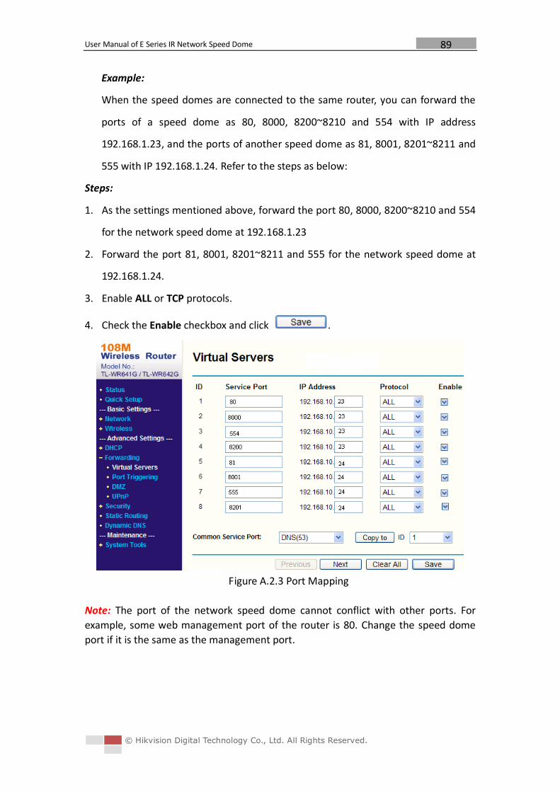
User Manual of E Series IR Network Speed Dome
© Hikvision Digital Technology Co., Ltd. All Rights Reserved.
89
Example:
When the speed domes are connected to the same router, you can forward the
ports of a speed dome as 80, 8000, 8200~8210 and 554 with IP address
192.168.1.23, and the ports of another speed dome as 81, 8001, 8201~8211 and
555 with IP 192.168.1.24. Refer to the steps as below:
Steps:
1. As the settings mentioned above, forward the port 80, 8000, 8200~8210 and 554
for the network speed dome at 192.168.1.23
2. Forward the port 81, 8001, 8201~8211 and 555 for the network speed dome at
192.168.1.24.
3. Enable ALL or TCP protocols.
4. Check the Enable checkbox and click .
Figure A.2.3 Port Mapping
Note: The port of the network speed dome cannot conflict with other ports. For
example, some web management port of the router is 80. Change the speed dome
port if it is the same as the management port.


![DS-2DF8442IXS-AELW (T2) 4MP 42× Network IR Speed Dome€¦ · Video Output 1.0V[p-p]/75Ω,PAL,NTS,N connector RS-485 HIKVISION, Pelco-P, Pelco-D, self-adaptive Supplement Light IR](https://img.pdfslide.us/doc/110x75/5fba73ffd2e67d671e7cce65/ds-2df8442ixs-aelw-t2-4mp-42-network-ir-speed-dome-video-output-10vp-p75palntsn.jpg)