Embed Size (px)
Citation preview

E-Series Networked DisplayInstallation Manual
Document Number: 87043_3Date: October 2007

Trademarks and registered trademarksAutohelm, HSB, Raymarine, RayTech, RayTech Navigator, Sail Pilot, SeaTalk and Sportpilot are registered trademarks of Raymarine Limited. Apelco is a registered trademark of Raymarine Holdings Limited (registered in all major marketing territories).
AST, Autoadapt, Auto GST, Autoseastate, Autotrim, Bidata, Marine Intelligence, Maxiview, On Board, Raychart, Raynav, Raypilot, Raystar, ST40, ST60, Seaclutter, Smart Route, Tridata and Waypoint Navigation are trademarks of Raymarine Limited.
Navionics is a registered trademark of Navionics Company, Italy. All other product names are trademarks or registered trademarks of their respective owners.
Copyright: ©Raymarine 2006
1
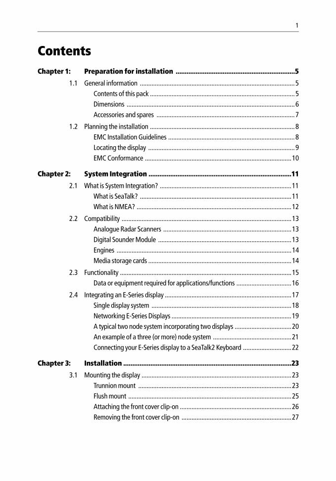
ContentsChapter 1: Preparation for installation ..................................................................5
1.1 General information .............................................................................................5Contents of this pack .......................................................................................5Dimensions .....................................................................................................6Accessories and spares ...................................................................................7
1.2 Planning the installation .......................................................................................8EMC Installation Guidelines ............................................................................8Locating the display ........................................................................................9EMC Conformance ........................................................................................10
Chapter 2: System Integration ...............................................................................11
2.1 What is System Integration? ...............................................................................11What is SeaTalk? ...........................................................................................11What is NMEA? .............................................................................................12
2.2 Compatibility ......................................................................................................13Analogue Radar Scanners .............................................................................13Digital Sounder Module ................................................................................13Engines .........................................................................................................14Media storage cards ......................................................................................14
2.3 Functionality .......................................................................................................15Data or equipment required for applications/functions .................................16
2.4 Integrating an E-Series display ............................................................................17Single display system ....................................................................................18Networking E-Series Displays ........................................................................19A typical two node system incorporating two displays ..................................20An example of a three (or more) node system ...............................................21Connecting your E-Series display to a SeaTalk2 Keyboard .............................22
Chapter 3: Installation .............................................................................................23
3.1 Mounting the display ..........................................................................................23Trunnion mount ............................................................................................23Flush mount ..................................................................................................25Attaching the front cover clip-on ...................................................................26Removing the front cover clip-on ..................................................................27
2 E-Series Installation Manual
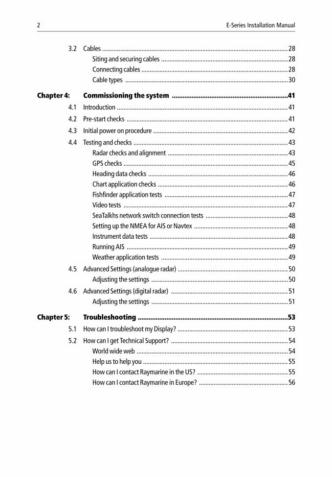
3.2 Cables .................................................................................................................28Siting and securing cables .............................................................................28Connecting cables .........................................................................................28Cable types ...................................................................................................30
Chapter 4: Commissioning the system .................................................................41
4.1 Introduction ........................................................................................................41
4.2 Pre-start checks ..................................................................................................41
4.3 Initial power on procedure ..................................................................................42
4.4 Testing and checks ..............................................................................................43Radar checks and alignment .........................................................................43GPS checks ....................................................................................................45Heading data checks .....................................................................................46Chart application checks ...............................................................................46Fishfinder application tests ...........................................................................47Video tests ....................................................................................................47SeaTalkhs network switch connection tests ..................................................48Setting up the NMEA for AIS or Navtex .........................................................48Instrument data tests ....................................................................................48Running AIS ..................................................................................................49Weather application tests .............................................................................49
4.5 Advanced Settings (analogue radar) ...................................................................50Adjusting the settings ...................................................................................50
4.6 Advanced Settings (digital radar) .......................................................................51Adjusting the settings ...................................................................................51
Chapter 5: Troubleshooting ....................................................................................53
5.1 How can I troubleshoot my Display? ...................................................................53
5.2 How can I get Technical Support? .......................................................................54World wide web ............................................................................................54Help us to help you ........................................................................................55How can I contact Raymarine in the US? .......................................................55How can I contact Raymarine in Europe? ......................................................56
Important Information 1
Important Information
Intended useThis handbook provides information and instructions to assist in planning and installing your Raymarine E-Series Networked Display, together with information that will be useful when you are connecting the E-Series Display to other equipment.
In order to obtain the best results in operation and performance, please read this handbook thoroughly.
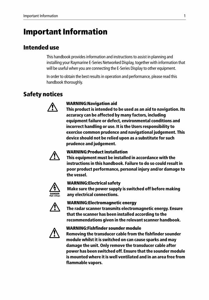
Safety noticesWARNING:Navigation aidThis product is intended to be used as an aid to navigation. Its accuracy can be affected by many factors, including equipment failure or defect, environmental conditions and incorrect handling or use. It is the Users responsibility to exercise common prudence and navigational judgement. This device should not be relied upon as a substitute for such prudence and judgement.
WARNING:Product installationThis equipment must be installed in accordance with the instructions in this handbook. Failure to do so could result in poor product performance, personal injury and/or damage to the vessel.
WARNING:Electrical safetyMake sure the power supply is switched off before making any electrical connections.
WARNING:Electromagnetic energyThe radar scanner transmits electromagnetic energy. Ensure that the scanner has been installed according to the recommendations given in the relevant scanner handbook.
WARNING:Fishfinder sounder moduleRemoving the transducer cable from the fishfinder sounder module whilst it is switched on can cause sparks and may damage the unit. Only remove the transducer cable after power has been switched off. Ensure that the sounder module is mounted where it is well ventilated and in an area free from flammable vapors.
2 E-Series Networked Display Installation Manual
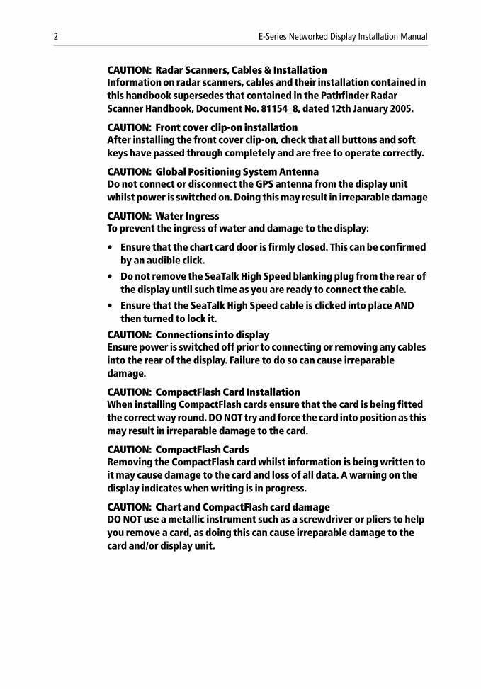
CAUTION: Radar Scanners, Cables & InstallationInformation on radar scanners, cables and their installation contained in this handbook supersedes that contained in the Pathfinder Radar Scanner Handbook, Document No. 81154_8, dated 12th January 2005.
CAUTION: Front cover clip-on installationAfter installing the front cover clip-on, check that all buttons and soft keys have passed through completely and are free to operate correctly.
CAUTION: Global Positioning System AntennaDo not connect or disconnect the GPS antenna from the display unit whilst power is switched on. Doing this may result in irreparable damage
CAUTION: Water IngressTo prevent the ingress of water and damage to the display:
• Ensure that the chart card door is firmly closed. This can be confirmed by an audible click.
• Do not remove the SeaTalk High Speed blanking plug from the rear of the display until such time as you are ready to connect the cable.
• Ensure that the SeaTalk High Speed cable is clicked into place AND then turned to lock it.
CAUTION: Connections into displayEnsure power is switched off prior to connecting or removing any cables into the rear of the display. Failure to do so can cause irreparable damage.
CAUTION: CompactFlash Card InstallationWhen installing CompactFlash cards ensure that the card is being fitted the correct way round. DO NOT try and force the card into position as this may result in irreparable damage to the card.
CAUTION: CompactFlash CardsRemoving the CompactFlash card whilst information is being written to it may cause damage to the card and loss of all data. A warning on the display indicates when writing is in progress.
CAUTION: Chart and CompactFlash card damageDO NOT use a metallic instrument such as a screwdriver or pliers to help you remove a card, as doing this can cause irreparable damage to the card and/or display unit.
Important Information 3
WarrantyTo register your new Raymarine product, please fill out the warranty card included in the box or go to: www.raymarine.com
It is important that you complete the owner information and return the card to receive full warranty benefits, including notification of software updates if they are required.
Certified Installation Raymarine recommends certified installation by a Raymarine approved installer. A certified installation qualifies for enhanced warranty benefits. Contact your Raymarine dealer for further details and refer to the separate warranty card packed with your product.
EMC ConformanceAll Raymarine equipment and accessories are designed to the best industry standards for use in the recreational marine environment.
The design and manufacture of Raymarine equipment and accessories conform to the appropriate Electromagnetic Compatibility (EMC) standards, but correct installation is required to ensure that performance is not compromised.
Handbook informationTo the best of our knowledge, the information in this handbook was correct when it went to press. However, Raymarine cannot accept liability for an inaccuracies or omissions it may contain.
In addition, our policy of continuous product improvement may change specifications without notice. Therefore Raymarine cannot accept liability for any differences between the product and the handbook.
Disposal
Waste Electrical and Electronic Equipment (WEEE) DirectiveThe WEEE Directive requires the recycling of waste electrical and electronic equipment. Whilst the WEEE Directive does not apply to some of Raymarine’s products, we support its requirements as part of our environmental policy and we ask you to be aware of how you should dispose of this product.
The crossed-out wheelie bin symbol found on our products signifies that it should not be disposed of in general waste or landfill.
Please contact your local dealer, national distributor or Raymarine Technical Services for information on product disposal.

4 E-Series Networked Display Installation Manual
Chapter 1: Preparation for installation 5
Chapter 1: Preparation for installation
1.1 General information
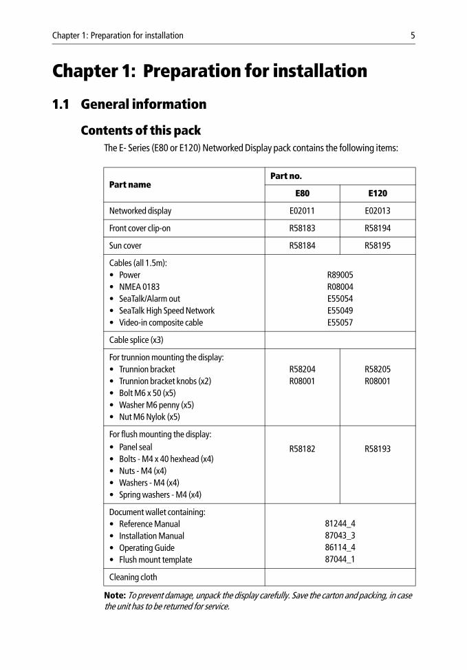
Contents of this packThe E- Series (E80 or E120) Networked Display pack contains the following items:
Note: To prevent damage, unpack the display carefully. Save the carton and packing, in case the unit has to be returned for service.
Part namePart no.
E80 E120
Networked display E02011 E02013
Front cover clip-on R58183 R58194
Sun cover R58184 R58195
Cables (all 1.5m):• Power• NMEA 0183• SeaTalk/Alarm out • SeaTalk High Speed Network • Video-in composite cable
R89005R08004E55054E55049E55057
Cable splice (x3)
For trunnion mounting the display:• Trunnion bracket• Trunnion bracket knobs (x2)• Bolt M6 x 50 (x5)• Washer M6 penny (x5)• Nut M6 Nylok (x5)
R58204R08001
R58205R08001
For flush mounting the display: • Panel seal• Bolts - M4 x 40 hexhead (x4)• Nuts - M4 (x4)• Washers - M4 (x4)• Spring washers - M4 (x4)
R58182 R58193
Document wallet containing:• Reference Manual• Installation Manual• Operating Guide• Flush mount template
81244_487043_386114_487044_1
Cleaning cloth
6 E-Series Installation Manual
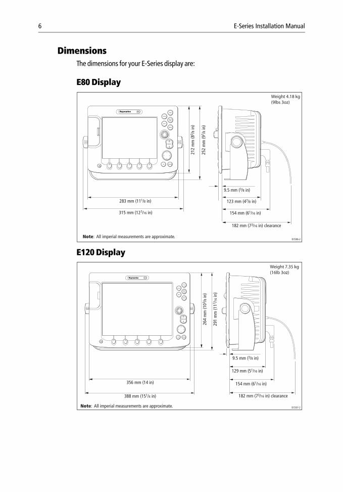
DimensionsThe dimensions for your E-Series display are:
E80 Display
E120 Display
CANCELOK
RANGE
IN
OUT
PAGE
ACTIVE
WPTSMOB
MENU
DATA
283 mm (111/8 in)
9.5 mm (3/8 in)
315 mm (127/16 in)
123 mm (47/8 in)
212
mm
(83 /
8 in)
252
mm
(97 /
8 in)
D7206-2
182 mm (73/16 in) clearance
154 mm (61/16 in)
Weight 4.18 kg(9lbs 3oz)
Note: All imperial measurements are approximate.
PAGE
ACTIVE
WPTSMOB
MENU
DATA
CANCELOK
RANGE
IN
OUT
Note: All imperial measurements are approximate.
264
mm
(103 /
8 in)
291
mm
(117 /
16 in
)
9.5 mm (3/8 in)
129 mm (51/16 in)
182 mm (73/16 in) clearance
154 mm (61/16 in)
D7207-2
356 mm (14 in)
388 mm (151/4 in)
Weight 7.35 kg(16lb 3oz)
Chapter 1: Preparation for installation 7
Accessories and sparesRaymarine accessories and parts can be obtained from your authorized Raymarine dealer. However, if you are in need of an item not available from the retailer or you are uncertain what item to choose for your Display, please contact Raymarine direct - See “How can I get Technical Support?” on page 54.
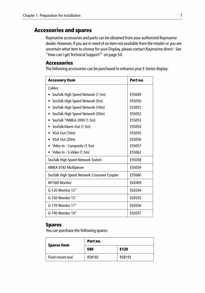
Accessories The following accessories can be purchased to enhance your E-Series display:
SparesYou can purchase the following spares:
Accessory item Part no.
Cables:
• SeaTalk High Speed Network (1.5m)
• SeaTalk High Speed Network (5m)
• SeaTalk High Speed Network (10m)
• SeaTalk High Speed Network (20m)
• SeaTalk 2/NMEA 2000 (1.5m)
• SeaTalk/Alarm Out (1.5m)
• VGA Out (10m)
• VGA Out (20m)
• Video In - Composite (1.5m)
• Video In - S-Video (1.5m)
E55049
E55050
E55051
E55052
E55053
E55054
E55055
E55056
E55057
E55062
SeaTalk High Speed Network Switch E55058
NMEA 0183 Multiplexer E55059
SeaTalk High Speed Network Crossover Coupler E55060
M1500 Monitor E02009
G-120 Monitor 12” E02034
G-150 Monitor 15" E02035
G-170 Monitor 17" E02036
G-190 Monitor 19" E02037
Spares itemPart no.
E80 E120
Flush mount seal R58182 R58193
8 E-Series Installation Manual
1.2 Planning the installationThis section provides information and advice for planning the installation of your Display.
EMC Installation GuidelinesAll Raymarine equipment and accessories are designed to the best industry standards for use in the recreational marine environment.
Their design and manufacture conforms to the appropriate Electromagnetic Compatibility (EMC) standards, but correct installation is required to ensure that performance is not compromised. Although every effort has been taken to ensure that they will perform under all conditions, it is important to understand what factors could affect the operation of the product.
The guidelines given here describe the conditions for optimum EMC performance, but it is recognized that it may not be possible to meet all of these conditions in all situations. To ensure the best possible conditions for EMC performance within the constraints imposed by any location, always ensure the maximum separation possible between different items of electrical equipment.
For optimum EMC performance, it is recommended that wherever possible:
• Raymarine equipment and cables connected to it are:
• At least 3 ft. (1 m) from any equipment transmitting or cables carrying radio sig-nals e.g. VHF radios, cables and antennas. In the case of SSB radios, the distance should be increased to 7 ft. (2 m).
• More than 7 ft. (2 m) from the path of a radar beam. A radar beam can normally be assumed to spread 20 degrees above and below the radiating element.
• The equipment is supplied from a separate battery from that used for engine start. Voltage drops below 10 V, and starter motor transients, can cause the equipment to reset. This will not damage the equipment, but may cause the loss of some infor-mation and may change the operating mode.
• Raymarine specified cables are used. Cutting and rejoining these cables can com-promise EMC performance and must be avoided unless doing so is detailed in the installation manual.
Front cover clip-on R58183 R58194
Sun cover R58184 R58195
Spares itemPart no.
E80 E120
Chapter 1: Preparation for installation 9
• If a suppression ferrite is attached to a cable, this ferrite should not be removed. If the ferrite needs to be removed during installation it must be reassembled in the same position.
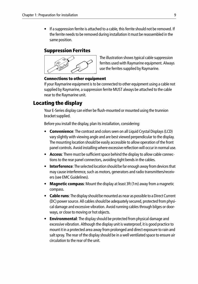
Suppression Ferrites The illustration shows typical cable suppression ferrites used with Raymarine equipment. Always use the ferrites supplied by Raymarine.
Connections to other equipmentIf your Raymarine equipment is to be connected to other equipment using a cable not supplied by Raymarine, a suppression ferrite MUST always be attached to the cable near to the Raymarine unit.
Locating the displayYour E-Series display can either be flush-mounted or mounted using the trunnion bracket supplied.
Before you install the display, plan its installation, considering:
• Convenience: The contrast and colors seen on all Liquid Crystal Displays (LCD) vary slightly with viewing angle and are best viewed perpendicular to the display. The mounting location should be easily accessible to allow operation of the front panel controls. Avoid installing where excessive reflection will occur in normal use.
• Access: There must be sufficient space behind the display to allow cable connec-tions to the rear panel connectors, avoiding tight bends in the cables.
• Interference: The selected location should be far enough away from devices that may cause interference, such as motors, generators and radio transmitters/receiv-ers (see EMC Guidelines).
• Magnetic compass: Mount the display at least 3ft (1m) away from a magnetic compass.
• Cable runs: The display should be mounted as near as possible to a Direct Current (DC) power source. All cables should be adequately secured, protected from physi-cal damage and excessive vibration. Avoid running cables through bilges or door-ways, or close to moving or hot objects.
• Environmental: The display should be protected from physical damage and excessive vibration. Although the display unit is waterproof, it is good practice to mount it in a protected area away from prolonged and direct exposure to rain and salt spray. The rear of the display should be in a well ventilated space to ensure air circulation to the rear of the unit.
D6626-1

10 E-Series Installation Manual
EMC ConformanceAlways check the installation before going to sea to make sure that it is not affected by radio transmissions, engine starting etc.
Chapter 2: System Integration 11
Chapter 2: System Integration
IntroductionThis chapter provides an overview of system integration, you may find that your system does not use all the protocols or contain all the instrumentation that is described in it. However it is hoped that the information supplied will help in your understanding of how systems can be integrated and used successfully.
2.1 What is System Integration?System integration enables various instruments and displays to communicate with each other and use the collected data to increase the functionality of the system.
This data exchange is only possible if the data gathering is accurate, and transfer between instruments is fast and accurate.
Fast and accurate data transfer is achieved by using a combination of the following data protocols:
• SeaTalk.
• SeaTalk2.
• National Marine Electronics Association (NMEA)0183.
• NMEA 2000.
• SeaTalkhs (High Speed).
When two or more E-Series Displays are networked, all shared data can be viewed on any display.
What is SeaTalk?
SeaTalkThe SeaTalk protocol enables compatible instruments to be connected to a simple network by way of a single cable carrying power (12 volts, 150 mA) and data in/out, without a central processor.
Additional instruments and functions can be added to a SeaTalk system, simply by plugging them into the network. SeaTalk equipment can also communicate with other non-SeaTalk equipment via the NMEA 0183 standard, provided a suitable interface is used.
SeaTalk2
SeaTalk2 is an enhanced replacement for SeaTalk and is a proprietary extension to NMEA 2000 and the proven CAN bus technology. It enables other Raymarine
12 E-Series Installation Manual
SeaTalk2 devices to talk to each other, whilst maintaining near transparent NMEA 2000 compatibility.
SeaTalkhs (High Speed)SeaTalk High Speed is designed to provide a ‘plug and play’, ethernet based marine network. It supports up to 8 nodes e.g. 7 displays and a DSM300/400, which can be connected to a compatible device, display, DSM etc. to give you access to all radar, fishfinder, chart cartridge and instrument data, waypoints, routes, tracks and navigation information held on the system.
What is NMEA?
NMEA 0183The NMEA 0183 Data Interface Standard was developed by the National Marine Electronics Association of America. It is an international standard to enable equipment from many different manufacturers to be connected together and share information.
The NMEA 0183 standard carries similar information to SeaTalk. However it has the important difference in that one cable will only carry information in one direction. For this reason NMEA 0183 is generally used to connect a data receiver and a transmitter together, e.g. a compass sensor transmitting heading to a radar display.
This information is passed in ‘sentences’, each of which has a three-letter sentence identifier. It is therefore important when checking compatibility between items that the same sentence identifiers are used:
• VTG - carries Course and Speed Over Ground data.
• GLL - carries latitude and longitude.
• DBT - carries water depth.
• MWV - carries relative wind angle and wind speed data.
NMEA 2000NMEA 2000 offers significant improvements over NMEA 0183, most notably in speed and connectivity. Up to 50 units can simultaneously transmit and receive on a single physical bus at any one time, with each node being physically addressable.
The standard was specifically intended to allow for a whole network of marine electronics from any manufacturer to communicate on a common bus via standardized message types and formats.
Chapter 2: System Integration 13
2.2 Compatibility
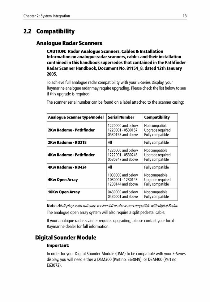
Analogue Radar ScannersCAUTION: Radar Analogue Scanners, Cables & InstallationInformation on analogue radar scanners, cables and their installation contained in this handbook supersedes that contained in the Pathfinder Radar Scanner Handbook, Document No. 81154_8, dated 12th January 2005.
To achieve full analogue radar compatibility with your E-Series Display, your Raymarine analogue radar may require upgrading. Please check the list below to see if this upgrade is required.
The scanner serial number can be found on a label attached to the scanner casing:
Note: All displays with software version 4.0 or above are compatible with digital Radar.
The analogue open array system will also require a split pedestal cable.
If your analogue radar scanner requires upgrading, please contact your local Raymarine dealer for full information.
Digital Sounder ModuleImportant:
In order for your Digital Sounder Module (DSM) to be compatible with your E-Series display, you will need either a DSM300 (Part no. E63049), or DSM400 (Part no E63072).
Analogue Scanner type/model Serial Number Compatibility
2Kw Radome - Pathfinder 1220000 and below1220001 - 05301570530158 and above
Not compatibleUpgrade requiredFully compatible
2Kw Radome - RD218 All Fully compatible
4Kw Radome - Pathfinder 1220000 and below1222001 - 05302460530247 and above
Not compatibleUpgrade requiredFully compatible
4Kw Radome - RD424 All Fully compatible
4Kw Open Array1030000 and below1030001 - 12301431230144 and above
Not compatibleUpgrade requiredFully compatible
10Kw Open Array 0430000 and below0430001 and above
Not compatibleFully compatible
14 E-Series Installation Manual
EnginesFor up-to-date information relating to compatible engines together with installation information, please refer to our website.
Media storage cards
Navionics Chart cardsTo use your E-Series Display as a navigation aid, charts with detailed information for the area you wish to navigate are required. The charts are available on Navionics® Chart cards.
A chart card provides an appropriate level of detail and scale for a given geographic area. Up to 6 Gold or 2 Platinum chart cards can be used in an E-Series Networked system. The maximum capacity Navionics card is 16Gb.
To obtain suitable Navionics Chart Cards, contact your local dealer or visit the Navionics web sites: www.navionics.com or www.navionics.it.
Alternatively, in North America call Navionics toll-free on 1-800-848-5896.
Outside of North America, contact your local dealer or call Navionics SpA on tel: (+39) 0584 961696 or fax: (+39) 0584 961309.
CompactFlash cardsIt is possible to archive or transfer information to and from your E-Series display and other compatible instruments using CompactFlash cards. To achieve the best results it is recommended that SAN DISK® CF memory cards are used.
Chapter 2: System Integration 15
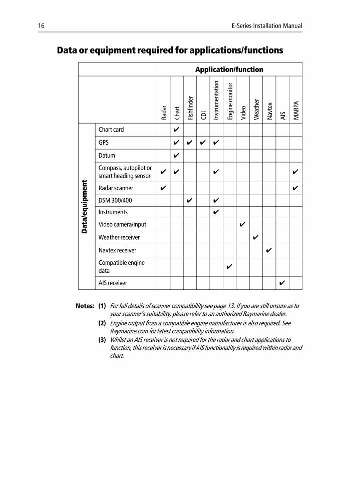
2.3 FunctionalityFor full functionality some applications require a dedicated transducer to provide specific data. The table on page 16 summarizes the data required by each application and the major functions of your E-Series Display.
In particular, position, heading and speed data are required for the following functions:
• Orientation - requires heading data derived from a suitable compass, for the radar to operate in North Up or Course Up mode and the chart to operate in Course Up and Head Up modes.
• Man Overboard (MOB) - requires heading and speed data. Alternatively, use speed over ground (SOG) and course over ground (COG) derived from the same source as position data (GPS).
• Mini Automatic Radar Plotting Aid (MARPA) and radar/chart over-lay functions - requires accurate heading data. MARPA functionality is pro-vided if SOG and COG are also available. Increased accuracy will be obtained by using fast heading data from a suitable compass, Smart heading sensor or com-patible Raymarine autopilot.
16 E-Series Installation Manual
Data or equipment required for applications/functions
Notes: (1) For full details of scanner compatibility see page 13. If you are still unsure as to your scanner’s suitability, please refer to an authorized Raymarine dealer.
(2) Engine output from a compatible engine manufacturer is also required. See Raymarine.com for latest compatibility information.
(3) Whilst an AIS receiver is not required for the radar and chart applications to function, this receiver is necessary if AIS functionality is required within radar and chart.
Application/function
Rada
r
Char
t
Fish
finde
r
CDI
Inst
rum
enta
tion
Engi
ne m
onito
r
Vide
o
Wea
ther
Nav
tex
AIS
MAR
PA
Dat
a/eq
uipm
ent
Chart card ✔
GPS ✔ ✔ ✔ ✔
Datum ✔
Compass, autopilot orsmart heading sensor
✔ ✔ ✔ ✔
Radar scanner ✔ ✔
DSM 300/400 ✔ ✔
Instruments ✔
Video camera/input ✔
Weather receiver ✔
Navtex receiver ✔
Compatible engine data
✔
AIS receiver ✔
Chapter 2: System Integration 17
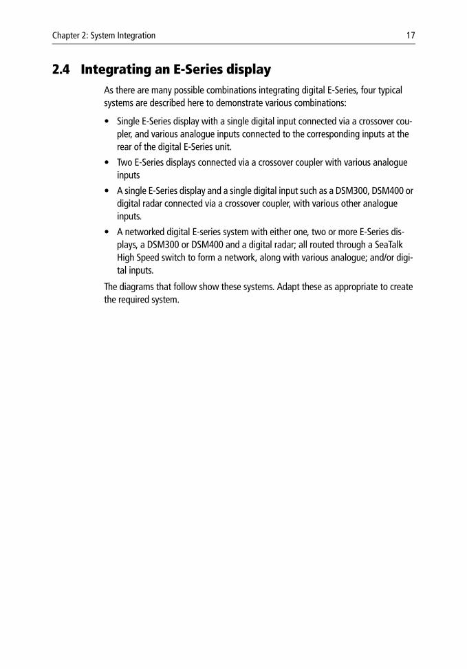
2.4 Integrating an E-Series displayAs there are many possible combinations integrating digital E-Series, four typical systems are described here to demonstrate various combinations:
• Single E-Series display with a single digital input connected via a crossover cou-pler, and various analogue inputs connected to the corresponding inputs at the rear of the digital E-Series unit.
• Two E-Series displays connected via a crossover coupler with various analogue inputs
• A single E-Series display and a single digital input such as a DSM300, DSM400 or digital radar connected via a crossover coupler, with various other analogue inputs.
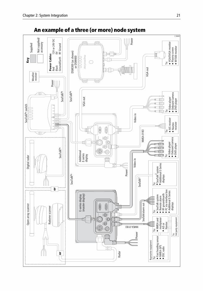
• A networked digital E-series system with either one, two or more E-Series dis-plays, a DSM300 or DSM400 and a digital radar; all routed through a SeaTalk High Speed switch to form a network, along with various analogue; and/or digi-tal inputs.
The diagrams that follow show these systems. Adapt these as appropriate to create the required system.
18 E-Series Installation Manual
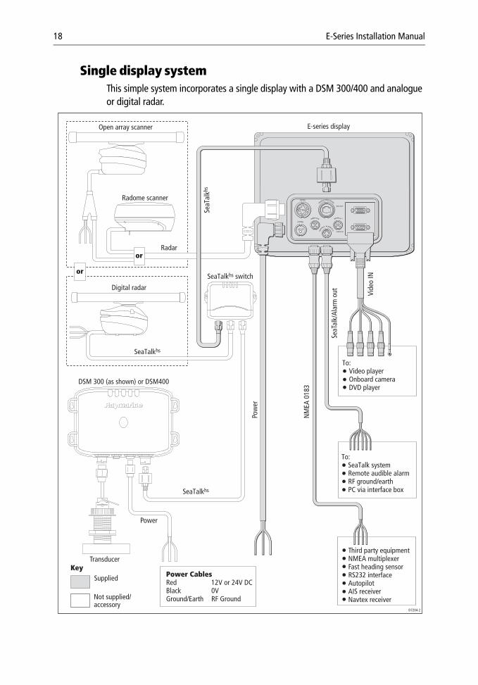
Single display systemThis simple system incorporates a single display with a DSM 300/400 and analogue or digital radar.
Power CablesRed 12V or 24V DCBlack 0VGround/Earth RF Ground
Third party equipmentNMEA multiplexerFast heading sensorRS232 interfaceAutopilotAIS receiverNavtex receiver
To: Video player Onboard camera DVD player
To: SeaTalk system Remote audible alarm RF ground/earth PC via interface box
SeaTalkhs switch
SeaT
alkh
s
SeaTalkhs
SeaTalkhs
Radar
Key
Power
Supplied
Not supplied/accessory
D7204-2
Transducer
Pow
er
NM
EA 0
183
Vide
o IN
SeaT
alk/
Alar
m o
ut
Open array scanner
Radome scanner
Digital radar
E-series display
DSM 300 (as shown) or DSM400
or
or
Chapter 2: System Integration 19
Networking E-Series DisplaysYou can connect two or more E-Series Displays to create a network. This will enable you to input, view and maintain data across all your Displays and enable multiple SeaTalk instruments to communicate with one another.
When you are installing a network of E-Series Displays you should note the following:
• One display will act as the master for SeaTalk, NMEA 0183 and system data including waypoints, routes and tracks. All SeaTalk/SeaTalk2 connections should be made to this master.
• If you connect the instrumentations master display (i.e. speed master) to all other displays in the system via SeaTalk or SeaTalk2, you will negate the need to unplug and reconnect cabling if the master becomes unavailable.
• The bridging of data from SeaTalk/SeaTalk2 only occurs at the master. You cannot therefore have additional networks connected to additional E-Series Displays. You can however connect multiple NMEA inputs.
• As it is not possible to view a video image across the network, you should con-nect the Video In cable to the display on which you wish to view the image.
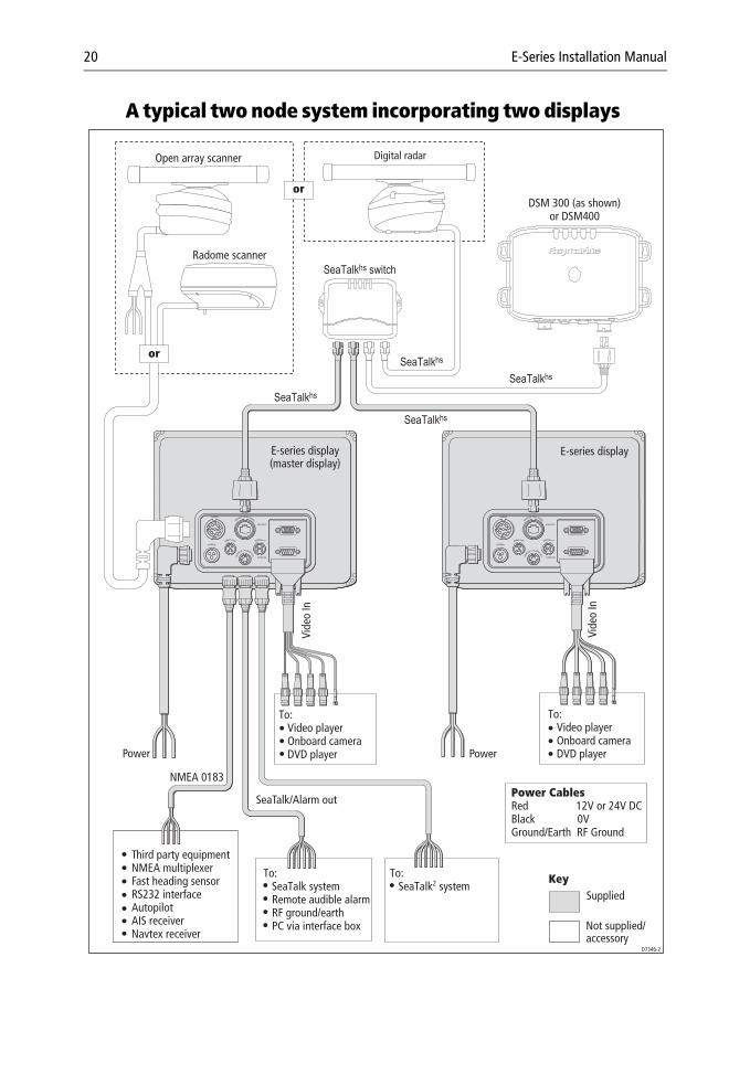
The following two pages detail a simple E-Series Networked System with two E-Series displays and Digital inputs (DSM & Radar) and a more advanced, multiple node system incorporating two (or more) displays and a DSM 300/400.
20 E-Series Installation Manual
A typical two node system incorporating two displays
Power CablesRed 12V or 24V DCBlack 0VGround/Earth RF Ground
To: SeaTalk2 system
To: SeaTalk system Remote audible alarm RF ground/earth PC via interface box
Third party equipmentNMEA multiplexerFast heading sensorRS232 interfaceAutopilotAIS receiverNavtex receiver
KeySupplied
Not supplied/accessory
Digital radar
DSM 300 (as shown)or DSM400
SeaTalkhs switch
SeaTalkhs
SeaTalkhs
SeaTalkhs
SeaTalkhs
Open array scanner
Radome scanner
or
or
To: Video player Onboard camera DVD player
To: Video player Onboard camera DVD playerPower Power
NMEA 0183
Vide
o In
SeaTalk/Alarm out
E-series display(master display)
D7346-2
Vide
o In
E-series display
Chapter 2: System Integration 21
An example of a three (or more) node system
To:
Fa
st h
eadi
ng s
enso
r
NM
EA G
PS
DS
C ra
dio
To:
Se
aTal
k sy
stem
Re
mot
e al
arm
RF g
roun
d/ea
rth
PC
via
inte
rface
box
Ad
ditio
nal E
-Ser
ies
di
spla
ys
To:
Se
aTal
k2 syst
em
Addi
tiona
l E-S
erie
s
disp
lays
To:
N
MEA
and
m
ultip
lexe
r
AIS
or
Nav
tex
Raym
arin
e eq
uipm
ent
To:
Vi
deo
play
er
Onb
oard
cam
era
DV
D pl
ayer
To:
Vi
deo
play
er
Onb
oard
cam
era
DV
D pl
ayer
To:
VG
A/SV
GA
mon
itor
Pl
asm
a sc
reen
M15
00 m
onito
r
Pow
er C
able
sRe
d 12
V or
24V
DC
Blac
k 0V
Gro
und/
Eart
h RF
Gro
und
Key
Not
sup
plie
d/ac
cess
ory
Supp
lied
D8992-2
To:
AI
S re
ceiv
er
Nav
tex
re
ceiv
erTo
:3r
d pa
rty
equi
pmen
t
Wea
ther
rece
iver
Rada
r
Ope
n ar
ray
scan
ner
Digi
tal r
adar
Rado
me
scan
ner
Pow
er
Vide
o in
SeaT
alk2
Vide
o in
VGA
out
VGA
out
Pow
er
NMEA 0183
NM
EA 0
183
SeaT
alk/
alar
m o
ut
Pow
er
DSM
300
(as
show
n)or
DSM
400
E-se
ries
disp
lay
(mas
ter d
ispl
ay)
Addi
tiona
lE-
serie
sdi
spla
y
SeaT
alkh
s sw
itch
SeaT
alkh
sSe
aTal
khs
SeaT
alkh
sSe
aTal
khs
Pow
er
or
or
22 E-Series Installation Manual
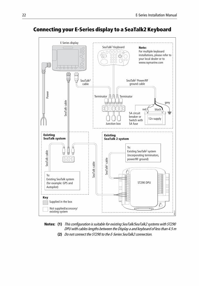
Connecting your E-Series display to a SeaTalk2 Keyboard
Notes: (1) This configuration is suitable for existing SeaTalk/SeaTalk2 systems with ST290 DPU with cables lengths between the Display a and keyboard of less than 4.5 m
(2) Do not connect the ST290 to the E-Series SeaTalk2 connection.
Key
SeaTalk2 Keyboard
Junction box
E Series display
TerminatorTerminator
SeaTalk2
cable
ST290 DPU
ExistingSeaTalk 2 system
ExistingSeaTalk system
SeaT
alk2
cab
le
SeaT
alk
cabl
e
SeaT
alk
cabl
e
SeaT
alk
cabl
e
Pow
er
12v supply
SeaTalk2 Power/RFground cable
5A circuitbreaker orSwitch with5A fuse
Not supplied/accessory/existing system
Supplied in the box
To:Existing SeaTalk system (for example: GPS and Autopilot)
To:Existing SeaTalk2 system (incorporating terminators, power/RF ground)
D901
3-1
grey
red black
Note:For multiple keyboard installations, please refer to your local dealer or to www.raymarine.com
Chapter 3: Installation 23
Chapter 3: InstallationCAUTION: Please ensure that you have read Chapter 1: Preparation for installation before proceeding.
CAUTION: Radar Scanners, Cables & InstallationInformation on radar scanners, cables and their installation contained in this handbook supersedes that contained in the Pathfinder Radar Scanner Handbook, Document No. 81154_8, dated 12th January 2005.
IntroductionThis chapter provides instructions for installing your E-Series Display. You may find that your system does not use all the protocols or contain all of the instrumentation that is described.
3.1 Mounting the displayCAUTION: InstallationMake sure there are no hidden electrical wires or other items behind the selected location before proceeding.
Make sure there is sufficient rear access for mounting AND cabling.
The display unit is waterproof to CFR 46 and can be installed either above or below deck using either the trunnion bracket or by flush mounting it in a suitable position.
Trunnion mountThe display unit can be fitted on a dash, chart table, bulkhead or deckhead, using the trunnion bracket:
You should fit the trunnion bracket as follows:
1. Mark the location of the trunnion bracket screw holes on the chosen mounting sur-face.
2. Drill pilot holes for the screws using a suitable drill, taking care that there are no cables or anything that may be damaged behind the surface.
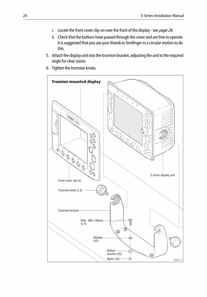
3. Use the 5 bolts supplied (together with the washers and nuts) to securely attach the bracket.
4. Before attaching the display unit to the bracket:
24 E-Series Installation Manual
i. Locate the front cover clip-on over the front of the display - see page 26.
ii. Check that the buttons have passed through the cover and are free to operate. It is suggested that you use your thumb or forefinger in a circular motion to do this.
5. Attach the display unit into the trunnion bracket, adjusting the unit to the required angle for clear vision.
6. Tighten the trunnion knobs.
D7211_1
E-series display unit
Trunnion knob (x 2)
Trunnion bracket
Bolt - M6 x 50mm(x 5)
Front cover clip-on
Trunnion mounted display
Buttonwasher (x5)
Washer(x5)
Nyloc (x5)
Chapter 3: Installation 25
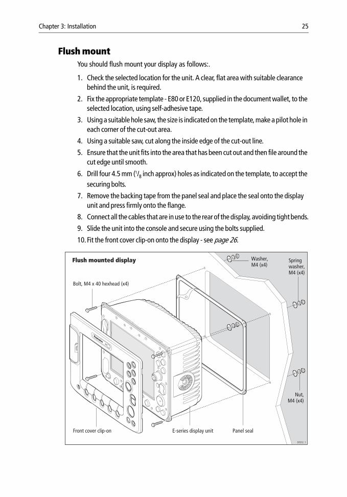
Flush mountYou should flush mount your display as follows:.
1. Check the selected location for the unit. A clear, flat area with suitable clearance behind the unit, is required.
2. Fix the appropriate template - E80 or E120, supplied in the document wallet, to the selected location, using self-adhesive tape.
3. Using a suitable hole saw, the size is indicated on the template, make a pilot hole in each corner of the cut-out area.
4. Using a suitable saw, cut along the inside edge of the cut-out line.
5. Ensure that the unit fits into the area that has been cut out and then file around the cut edge until smooth.
6. Drill four 4.5 mm (1/8 inch approx) holes as indicated on the template, to accept the securing bolts.
7. Remove the backing tape from the panel seal and place the seal onto the display unit and press firmly onto the flange.
8. Connect all the cables that are in use to the rear of the display, avoiding tight bends.
9. Slide the unit into the console and secure using the bolts supplied.
10.Fit the front cover clip-on onto the display - see page 26.
Flush mounted display
D7212_1
E-series display unit
Bolt, M4 x 40 hexhead (x4)
Spring washer,M4 (x4)
Washer,M4 (x4)
Nut,M4 (x4)
Front cover clip-on Panel seal
26 E-Series Installation Manual
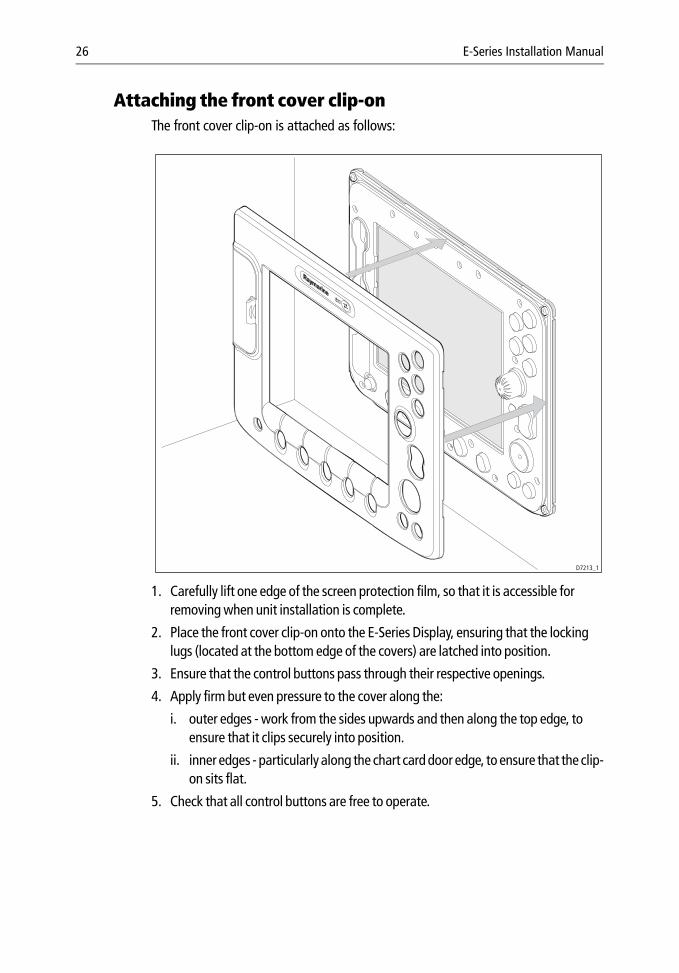
Attaching the front cover clip-onThe front cover clip-on is attached as follows:
1. Carefully lift one edge of the screen protection film, so that it is accessible for removing when unit installation is complete.
2. Place the front cover clip-on onto the E-Series Display, ensuring that the locking lugs (located at the bottom edge of the covers) are latched into position.
3. Ensure that the control buttons pass through their respective openings.
4. Apply firm but even pressure to the cover along the:
i. outer edges - work from the sides upwards and then along the top edge, to ensure that it clips securely into position.
ii. inner edges - particularly along the chart card door edge, to ensure that the clip-on sits flat.
5. Check that all control buttons are free to operate.
D7213_1
Chapter 3: Installation 27
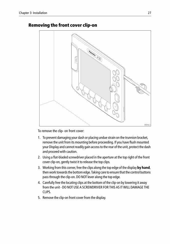
Removing the front cover clip-on
To remove the clip- on front cover:
1. To prevent damaging your dash or placing undue strain on the trunnion bracket, remove the unit from its mounting before proceeding. If you have flush mounted your Display and cannot readily gain access to the rear of the unit, protect the dash and proceed with caution.
2. Using a flat-bladed screwdriver placed in the aperture at the top right of the front cover clip-on, gently twist it to release the top clips.
3. Working from this corner, free the clips along the top edge of the display by hand, then work towards the bottom edge. Taking care to ensure that the control buttons pass through the clip-on. DO NOT lever along the top edge.
4. Carefully free the locating clips at the bottom of the clip-on by lowering it away from the unit - DO NOT USE A SCREWDRIVER FOR THIS AS IT WILL DAMAGE THE CLIPS.
5. Remove the clip-on front cover from the display.
D7214_1
28 E-Series Installation Manual
3.2 CablesThis section details how to install and connect all the relevant cables to your E-Series Display.
Siting and securing cablesWhen installing system cables, please note the following:
• All cables should be adequately secured, protected from physical damage and exposure to heat. Avoid running cables through bilges or doorways, or close to moving or hot objects.
• Connectors should be protected from damage. If it proves necessary to pull cables through a bulkhead or deckhead using a cord, this should be attached several inches behind the connector. Do not attach a tie immediately behind or around the connector.
• Acute bends must be avoided.
• Where a cable passes through an exposed bulkhead or deckhead, a watertight feed-through should be used.
• Secure cables in place using tie-wraps or lacing twine. Coil any extra cable and tie it out of the way.
• Do not remove the SeaTalk High Speed blanking plug from the rear of the display until such time as you are ready to connect the cable. Failure to adhere to this, may result in the ingress of water and permanent damage to the display.
Connecting cablesWARNING: To avoid damaging the multi functional display, ensure the display and all peripherals to be connected are powered down.
CAUTION: Do not remove the SeaTalk High Speed blanking plug from the rear of the display until such time as you are ready to connect the cable. Failure to adhere to this may result in water ingress and permanent damage to the display.
To ensure that your E-Series Display functions correctly, you will need to connect the following cables:
• SeaTalk/Alarm Out cable (if SeaTalk system connected).
• NMEA cable (if third party equipment, NMEA multiplexer, fast heading sensor, RS232 interface or course computer fitted).
• SeaTalk2 cable (if Sea Talk2 system connected).
• SeaTalk High Speed cable (if a DSM or second display is fitted).
• Video In cable (if a video player, on-board camera or DVD player fitted).
Chapter 3: Installation 29
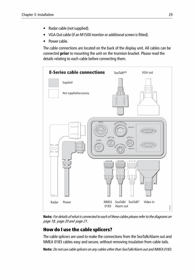
• Radar cable (not supplied).
• VGA Out cable (if an M1500 monitor or additional screen is fitted).
• Power cable.
The cable connections are located on the back of the display unit. All cables can be connected prior to mounting the unit on the trunnion bracket. Please read the details relating to each cable before connecting them.
Note: For details of what is connected to each of these cables please refer to the diagrams on page 18, page 20 and page 21.
How do I use the cable splicers?The cable splicers are used to make the connections from the SeaTalk/Alarm out and NMEA 0183 cables easy and secure, without removing insulation from cable tails.
Note: Do not use cable splicers on any cables other than SeaTalk/Alarm out and NMEA 0183.
D721
0-1
VGA outSeaTalkHS
Supplied
Not supplied/accessory
Radar Power NMEA0183
SeaTalk/Alarm out
SeaTalk2 Video in
E-Series cable connections
30 E-Series Installation Manual
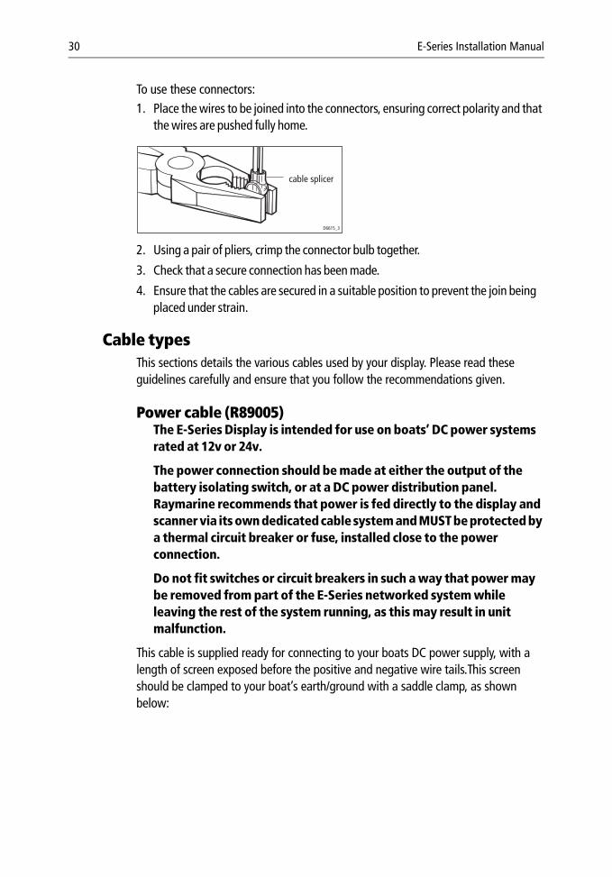
To use these connectors:1. Place the wires to be joined into the connectors, ensuring correct polarity and that
the wires are pushed fully home.
2. Using a pair of pliers, crimp the connector bulb together.
3. Check that a secure connection has been made.
4. Ensure that the cables are secured in a suitable position to prevent the join being placed under strain.
Cable typesThis sections details the various cables used by your display. Please read these guidelines carefully and ensure that you follow the recommendations given.
Power cable (R89005)The E-Series Display is intended for use on boats’ DC power systems rated at 12v or 24v.
The power connection should be made at either the output of the battery isolating switch, or at a DC power distribution panel. Raymarine recommends that power is fed directly to the display and scanner via its own dedicated cable system and MUST be protected by a thermal circuit breaker or fuse, installed close to the power connection.
Do not fit switches or circuit breakers in such a way that power may be removed from part of the E-Series networked system while leaving the rest of the system running, as this may result in unit malfunction.
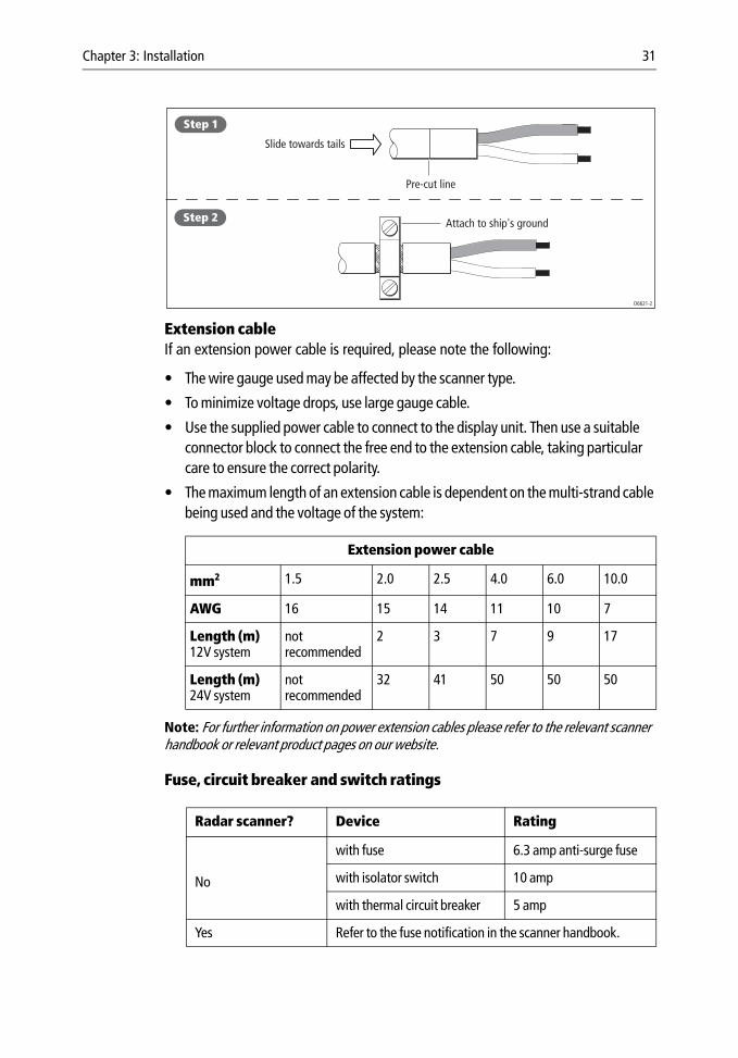
This cable is supplied ready for connecting to your boats DC power supply, with a length of screen exposed before the positive and negative wire tails.This screen should be clamped to your boat’s earth/ground with a saddle clamp, as shown below:
cable splicer
D6615_3
Chapter 3: Installation 31
Extension cableIf an extension power cable is required, please note the following:
• The wire gauge used may be affected by the scanner type.
• To minimize voltage drops, use large gauge cable.
• Use the supplied power cable to connect to the display unit. Then use a suitable connector block to connect the free end to the extension cable, taking particular care to ensure the correct polarity.
• The maximum length of an extension cable is dependent on the multi-strand cable being used and the voltage of the system:
Note: For further information on power extension cables please refer to the relevant scanner handbook or relevant product pages on our website.
Fuse, circuit breaker and switch ratings
Extension power cable
mm2 1.5 2.0 2.5 4.0 6.0 10.0
AWG 16 15 14 11 10 7
Length (m)12V system
notrecommended
2 3 7 9 17
Length (m)24V system
notrecommended
32 41 50 50 50
Radar scanner? Device Rating
No
with fuse 6.3 amp anti-surge fuse
with isolator switch 10 amp
with thermal circuit breaker 5 amp
Yes Refer to the fuse notification in the scanner handbook.
Slide towards tails
Pre-cut line
Attach to ship's ground
Step 1
Step 2
D6621-2
32 E-Series Installation Manual
Do not fit switches or circuit breakers in such a way that power may be removed from part of the E-Series networked system while leaving the rest of the system running, as this may result in unit malfunction.
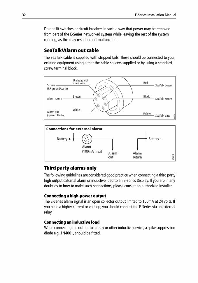
SeaTalk/Alarm out cableThe SeaTalk cable is supplied with stripped tails. These should be connected to your existing equipment using either the cable splicers supplied or by using a standard screw terminal block.
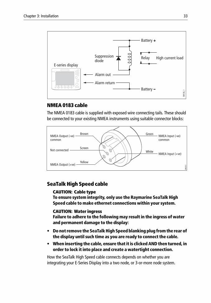
Third party alarms onlyThe following guidelines are considered good practice when connecting a third party high output external alarm or inductive load to an E-Series Display. If you are in any doubt as to how to make such connections, please consult an authorized installer.
Connecting a high-power outputThe E-Series alarm signal is an open collector output limited to 100mA at 24 volts. If you need a higher current or voltage, you should connect the E-Series via an external relay.
Connecting an inductive loadWhen connecting the output to a relay or other inductive device, a spike suppression diode e.g. 1N4001, should be fitted.
D901
8-1
Alarm out(open collector) SeaTalk data
SeaTalk return
SeaTalk powerScreen(RF ground/earth)
Red
Alarm return
Unsheathed/drain wire
Brown
WhiteYellow
Black
D748
2-2
Alarm(100mA max) Alarm
outAlarm return
Battery -Battery +
Connections for external alarm
Chapter 3: Installation 33
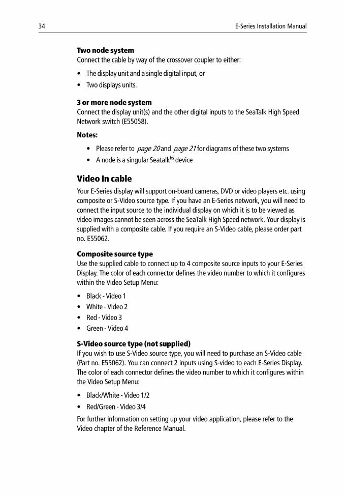
NMEA 0183 cable The NMEA 0183 cable is supplied with exposed wire connecting tails. These should be connected to your existing NMEA instruments using suitable connector blocks:
SeaTalk High Speed cableCAUTION: Cable typeTo ensure system integrity, only use the Raymarine SeaTalk High Speed cable to make ethernet connections within your system.
CAUTION: Water ingressFailure to adhere to the following may result in the ingress of water and permanent damage to the display:
• Do not remove the SeaTalk High Speed blanking plug from the rear of the display until such time as you are ready to connect the cable.
• When inserting the cable, ensure that it is clicked AND then turned, in order to lock it into place and create a watertight connection.
How the SeaTalk High Speed cable connects depends on whether you are integrating your E-Series Display into a two node, or 3-or-more node system.
High current load
Battery +
Battery --Alarm return
Alarm out
RelaySuppressiondiode
E-series display
D813
6_1
D901
9-1
Not connected
BrownNMEA Input (-ve)common
NMEA Output (-ve)common
NMEA Output (+ve)
NMEA Input (+ve)
Green
Screen
Yellow
White
34 E-Series Installation Manual
Two node system Connect the cable by way of the crossover coupler to either:
• The display unit and a single digital input, or
• Two displays units.
3 or more node systemConnect the display unit(s) and the other digital inputs to the SeaTalk High Speed Network switch (E55058).
Notes:
• Please refer to page 20 and page 21 for diagrams of these two systems
• A node is a singular Seatalkhs device
Video In cableYour E-Series display will support on-board cameras, DVD or video players etc. using composite or S-Video source type. If you have an E-Series network, you will need to connect the input source to the individual display on which it is to be viewed as video images cannot be seen across the SeaTalk High Speed network. Your display is supplied with a composite cable. If you require an S-Video cable, please order part no. E55062.
Composite source typeUse the supplied cable to connect up to 4 composite source inputs to your E-Series Display. The color of each connector defines the video number to which it configures within the Video Setup Menu:
• Black - Video 1• White - Video 2• Red - Video 3• Green - Video 4
S-Video source type (not supplied)If you wish to use S-Video source type, you will need to purchase an S-Video cable (Part no. E55062). You can connect 2 inputs using S-video to each E-Series Display. The color of each connector defines the video number to which it configures within the Video Setup Menu:
• Black/White - Video 1/2
• Red/Green - Video 3/4
For further information on setting up your video application, please refer to the Video chapter of the Reference Manual.
Chapter 3: Installation 35
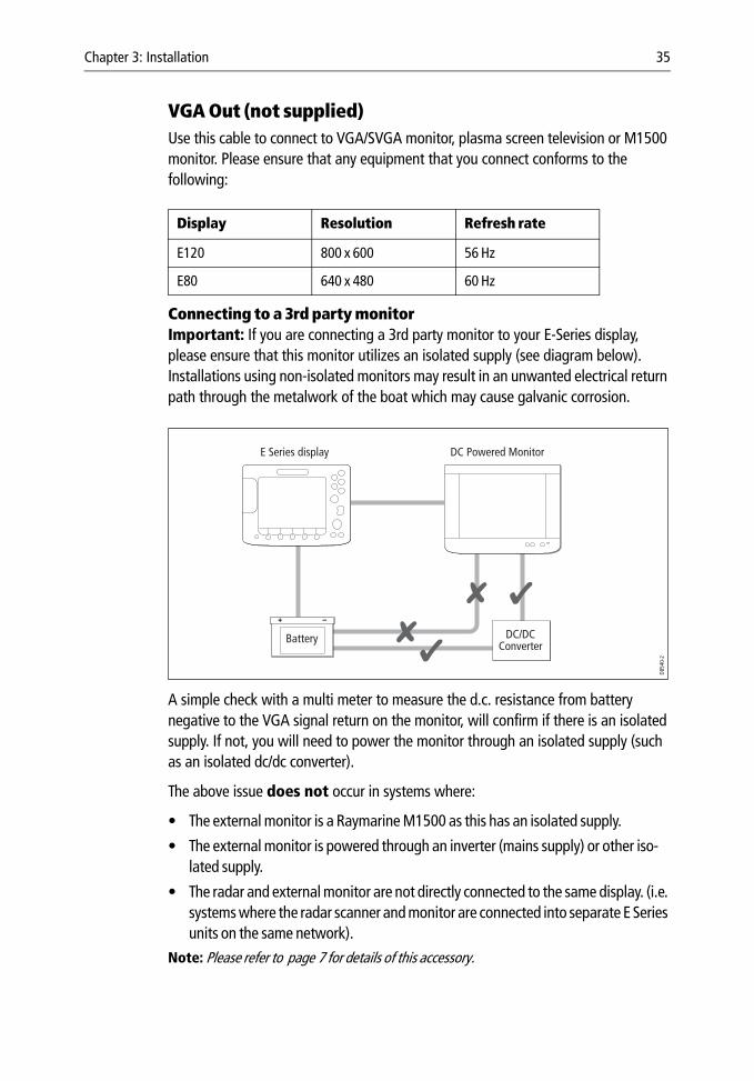
VGA Out (not supplied)Use this cable to connect to VGA/SVGA monitor, plasma screen television or M1500 monitor. Please ensure that any equipment that you connect conforms to the following:
Connecting to a 3rd party monitorImportant: If you are connecting a 3rd party monitor to your E-Series display, please ensure that this monitor utilizes an isolated supply (see diagram below). Installations using non-isolated monitors may result in an unwanted electrical return path through the metalwork of the boat which may cause galvanic corrosion.
A simple check with a multi meter to measure the d.c. resistance from battery negative to the VGA signal return on the monitor, will confirm if there is an isolated supply. If not, you will need to power the monitor through an isolated supply (such as an isolated dc/dc converter).
The above issue does not occur in systems where:
• The external monitor is a Raymarine M1500 as this has an isolated supply.
• The external monitor is powered through an inverter (mains supply) or other iso-lated supply.
• The radar and external monitor are not directly connected to the same display. (i.e. systems where the radar scanner and monitor are connected into separate E Series units on the same network).
Note: Please refer to page 7 for details of this accessory.
Display Resolution Refresh rate
E120 800 x 600 56 Hz
E80 640 x 480 60 Hz
DC/DCConverter
Battery
E Series display DC Powered Monitor
D854
0-2
36 E-Series Installation Manual
SeaTalk2 (not supplied)
Use this cable to connect to third party equipment or SeaTalk2 instruments.
If your system networks two or more E-Series displays, you should ensure that the SeaTalk 2 connection is made to the display that you have defined as your master unit.
Note: Please refer to page 7 for details of this accessory.
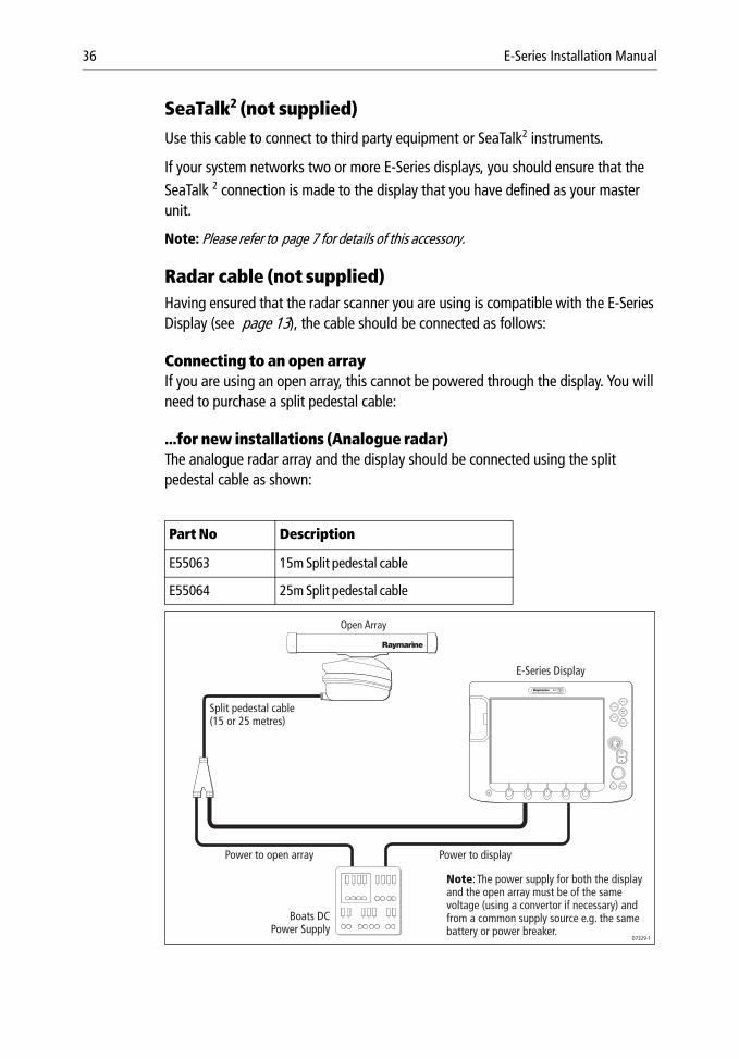
Radar cable (not supplied)Having ensured that the radar scanner you are using is compatible with the E-Series Display (see page 13), the cable should be connected as follows:
Connecting to an open arrayIf you are using an open array, this cannot be powered through the display. You will need to purchase a split pedestal cable:
...for new installations (Analogue radar)The analogue radar array and the display should be connected using the split pedestal cable as shown:
Part No Description
E55063 15m Split pedestal cable
E55064 25m Split pedestal cable
PAGE
ACTIVE
WPTSMOB
MENU
DATA
CANCELOK
RANGE
IN
OUT
D7329-1
Open Array
Boats DCPower Supply
E-Series Display
Power to displayPower to open array
Split pedestal cable(15 or 25 metres)
Note: The power supply for both the display and the open array must be of the same voltage (using a convertor if necessary) and from a common supply source e.g. the same battery or power breaker.
Chapter 3: Installation 37
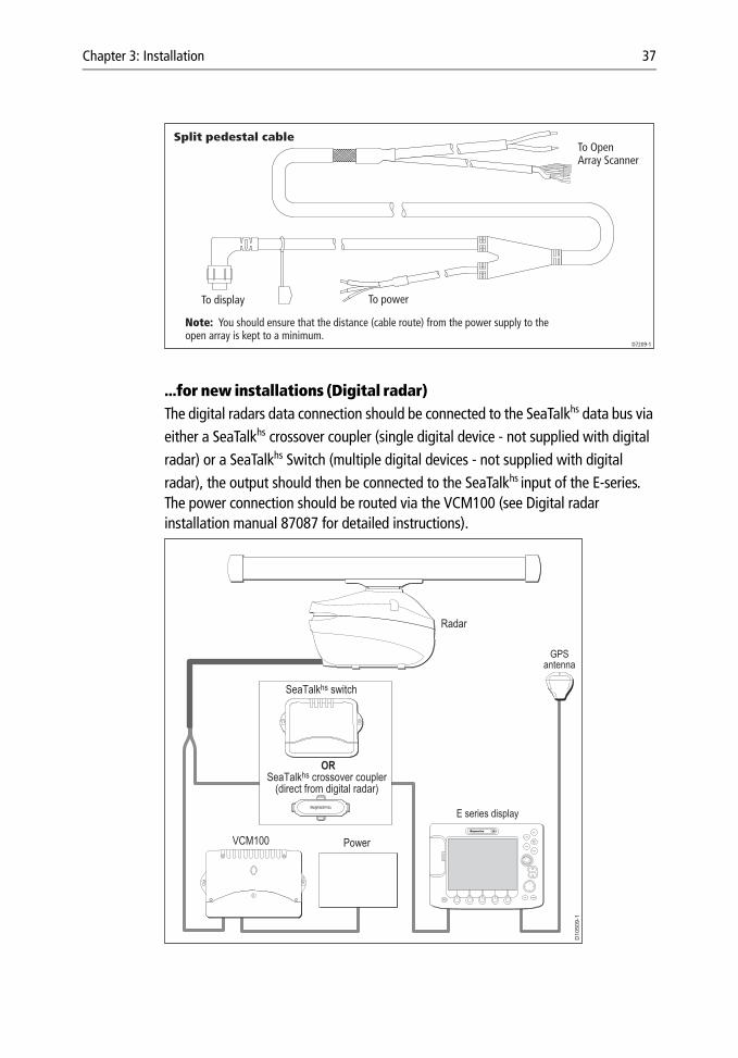
...for new installations (Digital radar)The digital radars data connection should be connected to the SeaTalkhs data bus via either a SeaTalkhs crossover coupler (single digital device - not supplied with digital radar) or a SeaTalkhs Switch (multiple digital devices - not supplied with digital radar), the output should then be connected to the SeaTalkhs input of the E-series. The power connection should be routed via the VCM100 (see Digital radar installation manual 87087 for detailed instructions).
Split pedestal cable
To display To power
To OpenArray Scanner
D7209-1
Note: You should ensure that the distance (cable route) from the power supply to theopen array is kept to a minimum.
D10509-1
Radar
PowerVCM100
SeaTalkhs switch
GPSantenna
E series display
CANCELOK
RANGE
IN
OUT
PAGE
ACTIVE
WPTSMOB
MENU
DATA
OR
SeaTalkhs crossover coupler(direct from digital radar)
38 E-Series Installation Manual
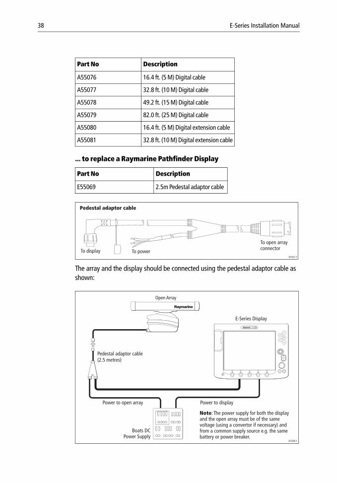
... to replace a Raymarine Pathfinder Display
The array and the display should be connected using the pedestal adaptor cable as shown:
Part No Description
A55076 16.4 ft. (5 M) Digital cable
A55077 32.8 ft. (10 M) Digital cable
A55078 49.2 ft. (15 M) Digital cable
A55079 82.0 ft. (25 M) Digital cable
A55080 16.4 ft. (5 M) Digital extension cable
A55081 32.8 ft. (10 M) Digital extension cable
Part No Description
E55069 2.5m Pedestal adaptor cable
Pedestal adaptor cable
D7327-1
To display
To open arrayconnectorTo power
Pedestal adaptor cable(2.5 metres)
PAGE
ACTIVE
WPTSMOB
MENU
DATA
CANCELOK
RANGE
IN
OUT
D7328-1
Open Array
Boats DCPower Supply
E-Series Display
Power to displayPower to open array
Note: The power supply for both the display and the open array must be of the same voltage (using a convertor if necessary) and from a common supply source e.g. the same battery or power breaker.
Chapter 3: Installation 39
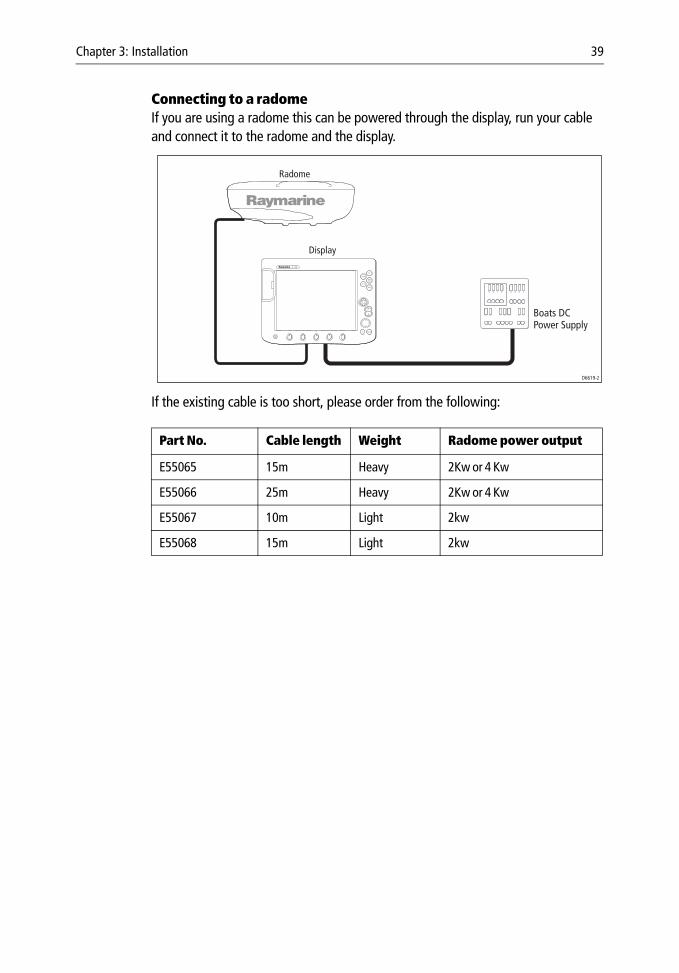
Connecting to a radomeIf you are using a radome this can be powered through the display, run your cable and connect it to the radome and the display.
If the existing cable is too short, please order from the following:
Part No. Cable length Weight Radome power output
E55065 15m Heavy 2Kw or 4 Kw
E55066 25m Heavy 2Kw or 4 Kw
E55067 10m Light 2kw
E55068 15m Light 2kw
RANGE
CANCELOK
PAGE
ACTIVE
WPTS/MOB
MENU
DATA
IN
OUT
Display
Boats DCPower Supply
D6619-2
Radome

40 E-Series Installation Manual
Chapter 4: Commissioning the system 41
Chapter 4: Commissioning the system
4.1 IntroductionThis chapter details the commissioning of your E-Series Display and includes the following:
• Required input.
• Pre-start checks.
• Initial power on procedure
• Radar checks and alignment.
• Chart application checks.
• Fishfinder checks.
• SeaTalk High Speed checks.
• Video in/out.
• AIS.
• Weather.
• Navtex.
4.2 Pre-start checksBefore you perform any functional tests, please carry out the following pre-start checks:
Radar• Check that the scanner has been installed in accordance with the installation man-
ual.
• All securing bolts should be fully tightened and any mechanical locking arrange-ments, as specified, are in place.
• Ensure scanner and power connections have been made; refer to the relevant install manual for correct connections and procedures.
• All connecting wires are secured and protected as necessary.
Note: If you are the boat’s owner and have installed the radar system, ask an authorized Ray-marine dealer to check and certify the installation before going to sea as your warranty could be affected.
WARNING:Electromagnetic energyThe radar scanner transmits electromagnetic energy. Ensure that the scanner has been installed according to the recommendations in the relevant scanner handbook. Ensure all personnel are clear of the scanner, before switching to transmit mode.
42 E-Series Installation Manual
FishfinderEnsure that the transducer cable is inserted and the bayonet connector locked onto the DSM 300/400.
GPSCheck that the GPS has a clear view of the sky and is not obstructed e.g. by buildings, bridges or other equipment fitted on-board.
Other equipmentFor details of pre-start checks for other equipment e.g. weather, AIS, please refer to the relevant handbook.
4.3 Initial power on procedure Once you have conducted the pre-start checks detailed in the previous section, you are ready to start the display:
1. Press the POWER button until the introductory logo is displayed:
• The keys light up and after a few seconds a navigation warning is displayed.• If you have networked two or more E-Series displays, you will also hear an
alarm and be asked to select the repeater displays. Press SET AS REPEATER on the appropriate Display(s).
• At this time the radar scanner (if fitted and powered) is checked for compatibil-ity with the display. An error message is displayed if the scanner is incompatible.
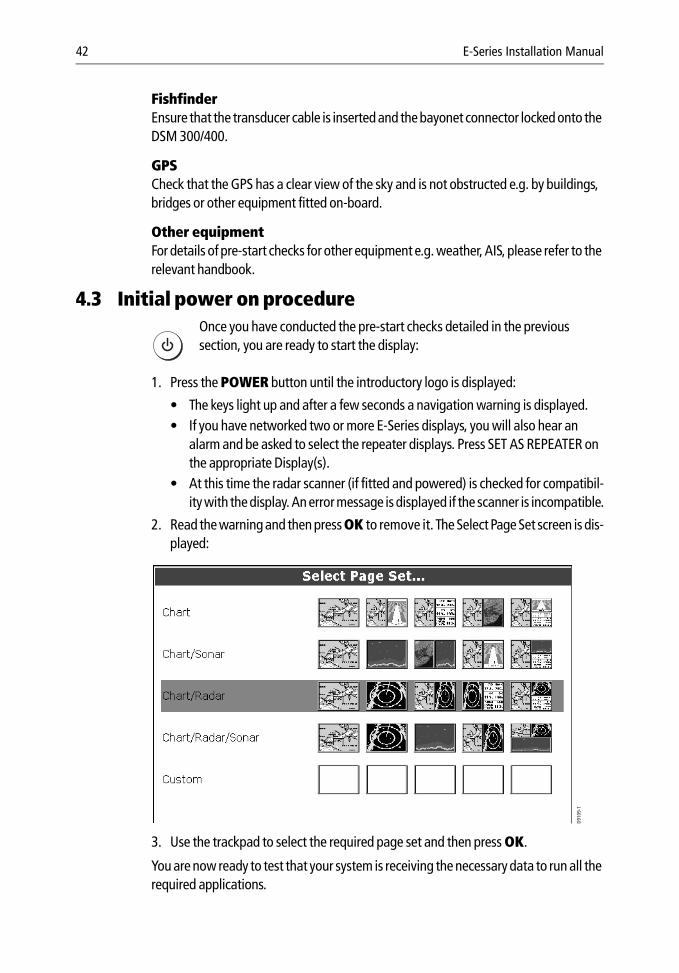
2. Read the warning and then press OK to remove it. The Select Page Set screen is dis-played:
3. Use the trackpad to select the required page set and then press OK.
You are now ready to test that your system is receiving the necessary data to run all the required applications.
D6577-1
D910
9-1
Chapter 4: Commissioning the system 43
4.4 Testing and checks
Radar checks and alignmentYour E-Series display is part of an integrated system. Raymarine strongly advise that you test and align the radar before connecting to other systems.
To test and align the radar you must first select a radar application. With the Select Page Set screen displayed (see previous section):
1. Press OK to select the highlighted page set.
2. Press PAGE. The currently selected page set is represented on the soft keys.3. Press the corresponding soft key to display a full window radar application.4. The scanner warm-up countdown commences. This will take 70 seconds (approx).
Note: If your scanner is incompatible, a message is displayed. If this is the case, you will be unable to proceed further with testing and aligning the radar. Refer to Important Informa-tion - Radar Scanners at the front of this handbook.
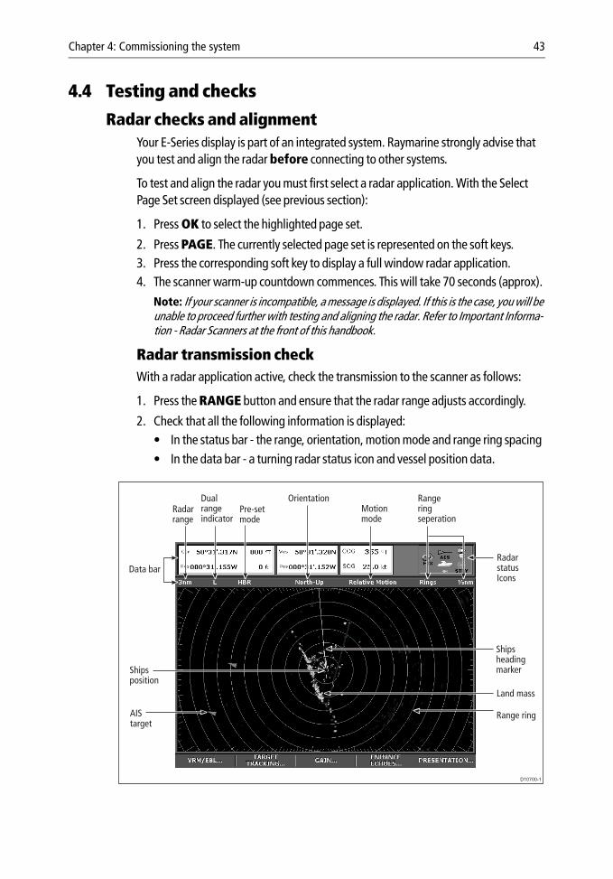
Radar transmission checkWith a radar application active, check the transmission to the scanner as follows:
1. Press the RANGE button and ensure that the radar range adjusts accordingly.
2. Check that all the following information is displayed:• In the status bar - the range, orientation, motion mode and range ring spacing • In the data bar - a turning radar status icon and vessel position data.
D10700-1
Dual rangeindicator
Radarstatus Icons
Shipsheading marker
Land mass
AIS target
Data bar
Shipsposition
Range ring
Rangeringseperation
Motionmode
OrientationPre-setmode
Radarrange
44 E-Series Installation Manual
Radar alignment checksYou should check the bearing alignment and display timing to ensure that an accurate picture is shown.
Adjusting the bearing alignment ensures that targets appear at the correct bearing relative to your boat’s bow. You need to select a visible target of known bearing that is displayed on the radar, and then adjust the radar set up as necessary until the correct bearing reading is obtained. You can carry out a bearing alignment in two ways:
Bearing alignment with your boat mooredTo use this method you will need a hand bearing compass:
1. Visually identify a suitable target, such as a buoy that can be seen towards the edge of the radar screen. Typically, this will be on the 1.5nm range.
2. Determine the accurate bearing of the target relative to your boat’s bow using the hand bearing compass. To do this subtract your boat head bearing from the target visual bearing, these examples may help:
3. From the primary radar soft keys, press VRM/EBL.4. Toggle the VRM/EBL soft key to ON. Adjust the EBL to your chosen target. If there is
a difference between your calculated bearing and that shown for the EBL, there is an alignment error and you will need to carry out bearing alignment adjustment (see below).
Bearing alignment with your boat under way1. Align your boat’s bow with the selected target.
2. Note the position of the target relative to the Ships Heading Marker (SHM) on the radar picture. If the target is not under the SHM, there is an alignment error and you will need to carry out bearing alignment adjustment. For details see below.
Adjusting the bearing alignment1. If moored, move the EBL to calculate bearing.
2. With a radar application in the active window, press MENU. The Set Up menu is dis-played.
Example 1 Example 2
Visual bearing (a) = 065° M Visual bearing (a) = 030° M
Ships head bearing (b) = 021° M Ships head bearing (b) = 042° M
Relative bearing:= (a) - (b)= 065 - 021 = 044° R
Relative bearing:= (a) - (b)= 030 - 042 = -012If answer is negative, add 360° = -012 + 360 = 348° R
Chapter 4: Commissioning the system 45
3. With RADAR SET UP highlighted, use the trackpad (right) to select the RADAR SET UP menu.
4. Use the trackpad (up/down) to highlight and then the trackpad (right) to select BEARING ALIGNMENT. The menu is removed from the screen and the Bearing Alignment soft key is displayed.
5. Press the BEARING ALIGNMENT softkey. 6. Proceed as follows:
• If the boat is moored - use the rotary control to place the selected target under the EBL.
• If the boat is under way - use the rotary control to place the selected target under the SHM.
7. The picture updates as the bearing alignment is adjusted.8. To exit the menu, press OK or CANCEL.
GPS checksThe GPS is used to position your boat on the chart. You can set up your Global Positioning System (GPS) and check its status using the GPS status icons and the GPS Status page of the Setup menu.
To access the GPS Status page:
1. Press MENU. The Setup menu is displayed.
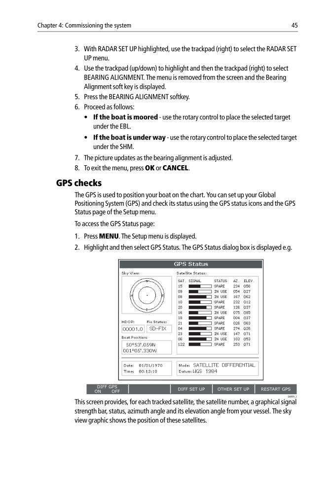
2. Highlight and then select GPS Status. The GPS Status dialog box is displayed e.g.
This screen provides, for each tracked satellite, the satellite number, a graphical signal strength bar, status, azimuth angle and its elevation angle from your vessel. The sky view graphic shows the position of these satellites.
DIFF SET UP OTHER SET UP RESTART GPSDIFF GPS
ON OFF
0
0
0
0
0
0
0
0
0
0
0
0
FIX STATUSHDOP
122
00001.0 SD-FIX
D6809_2
SATELLITE DIFFERENTIAL
WGS 1984
46 E-Series Installation Manual
Positional accuracy is dependent upon these parameters; in particular, the azimuth and elevation angles are used in a triangulation process to calculate your position. Horizontal Dilution of Position (HDOP) is a measure of this accuracy; a higher figure signifies a greater positional error. In ideal circumstances, the figure should be in the region of 1.0.
When a connection has been successfully made, the GPS status icon in the top right-hand corner of the screen reads FIX.
If NO FIX is displayed, please refer to the Troubleshooting section on page 53.
The option to select differential or satellite differential fix is dependent upon the capabilities of the attached GPS. If your boat is equipped with a Raymarine GPS, the Differential GPS can be switched on or off using the appropriate soft key.
Heading data checksIf your display is connected to a compass, autopilot or fast heading sensor, your boat’s heading will be displayed in the data bar. If heading data is not available your display can use COG data. This will however affect the operation of the following functions:
• overlay a radar image over your chart.
• orientate a radar image north-up.
• MARPA.
To linearize (‘swing’) your compass proceed as follows:
1. Press MENU.
2. Select the Compass Setup sub-menu.3. Press LINEARIZE COMPASS and follow the instructions displayed on screen. When
instructed to align heading, press the ALIGN HEADING soft key and then turn the rotary control one click at a time to fine tune the heading.
Chart application checksFor full functionality of chart applications, you need to ensure that position data is available at the display via SeaTalk, NMEA, SeaTalk2 or SeaTalk High Speed. To use your chart as a navigation aid you will need a chart card (see page 14) with the appropriate level of detail for the geographic area that you wish to navigate.
Proceed as follows:
1. Without a chart card installed, press PAGE.
2. Select a full window chart application by pressing the associated key.3. Zoom out with the RANGE button until the world map is visible.4. To ensure that the display is responding to position data:
i. Press FIND SHIP.
D745
3_1
Chapter 4: Commissioning the system 47
ii. Check that the cursor is positioned over the boat symbol in the centre of the dis-play.
5. Insert a chart card containing a suitable chart for the area in which you are located. Once inserted, the chart should redraw with the cartridge chart boundaries dis-played.
Note: For details of how to insert a chart card, please refer to Section 2.7, Using Compact-Flash cards in the Reference Manual.
6. Zoom in with the RANGE button to check that chart data is being displayed.
Fishfinder application testsFor the fishfinder application to function it must be connected to a DSM 300 or a DSM400. The status of your DSM is indicated by the boat/fish icon in the data bar (top right-hand corner of the screen)
Note: For set-up and commissioning instructions for your DSM, please refer to your DSM’s commissioning guide.
To test your DSM connection:
1. Press PAGE and select a full window fishfinder application.
2. Using the soft keys, check that individual settings change as they are selected.
Video testsTo ensure that the video application is operating you should open a video application on each display that is connected to a video input/output and check the following:
• Video in - check that an image is being displayed for each input.
Note: If you are using S-Video rather than composite input, you will need to change the settings in the Video Setup Menu. Please refer to the Reference Manual for more details.
DSM status icon DSM status description
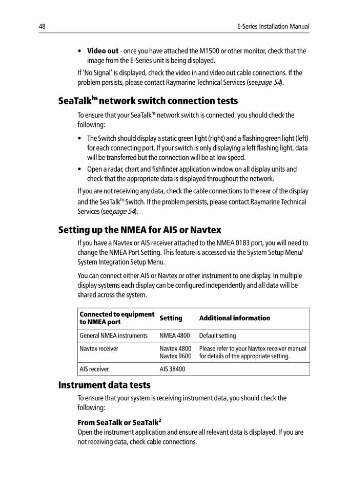
Successful connection to a DSM and transmitting.
DSM connected but not transmitting.
No DSM connected/recognized.
D689
2-3
(animated icon)
D745
1-1
(static icon)
D745
2-1
(greyed-out icon)
48 E-Series Installation Manual
• Video out - once you have attached the M1500 or other monitor, check that the image from the E-Series unit is being displayed.
If ‘No Signal’ is displayed, check the video in and video out cable connections. If the problem persists, please contact Raymarine Technical Services (seepage 54).
SeaTalkhs network switch connection testsTo ensure that your SeaTalkhs network switch is connected, you should check the following:
• The Switch should display a static green light (right) and a flashing green light (left) for each connecting port. If your switch is only displaying a left flashing light, data will be transferred but the connection will be at low speed.
• Open a radar, chart and fishfinder application window on all display units and check that the appropriate data is displayed throughout the network.
If you are not receiving any data, check the cable connections to the rear of the display and the SeaTalkhs Switch. If the problem persists, please contact Raymarine Technical Services (seepage 54).
Setting up the NMEA for AIS or NavtexIf you have a Navtex or AIS receiver attached to the NMEA 0183 port, you will need to change the NMEA Port Setting. This feature is accessed via the System Setup Menu/System Integration Setup Menu.
You can connect either AIS or Navtex or other instrument to one display. In multiple display systems each display can be configured independently and all data will be shared across the system.
Instrument data testsTo ensure that your system is receiving instrument data, you should check the following:
From SeaTalk or SeaTalk2
Open the instrument application and ensure all relevant data is displayed. If you are not receiving data, check cable connections.
Connected to equipment to NMEA port Setting Additional information
General NMEA instruments NMEA 4800 Default setting
Navtex receiver Navtex 4800Navtex 9600
Please refer to your Navtex receiver manual for details of the appropriate setting.
AIS receiver AIS 38400
Chapter 4: Commissioning the system 49
From third party devices on NMEA 0183Check that appropriate NMEA sentences are being sent from the third party device and on the E-Series Display. Open the instrument application and ensure all relevant data is displayed.
Running AISIn order to run AIS, you will need:
• A receive only AIS unit or a full transponder.
A receiver will allow you to receive data about other vessels in your area but will not allow other vessels to ‘see’ you. A full transponder transmits and receives AIS data and therefore allows you to receive data about other vessels and for other AIS equipped vessels to see and receive information about your vessel. This could include position, course, speed and rate of turn data.
• A VHF antenna (part of an AIS system).
• A GPS.
• A Compass - although not essential, this will enhance performance.
When the AIS unit is connected to the E-Series display, the status of the unit is indicated by an AIS icon in the transducer data box.
You will now need to specify the 38,400 baud rate for the NMEA port that communicates with the AIS transceivers and receivers (see the table on page 48).
Weather application testsTo test your Weather application create and open a weather window (see the Weather Chapter of the Reference Manual). If your E-Series is receiving information from the weather receiver the following will be displayed:
• The signal strength status (High, Medium or Low) in the status bar. If ‘No connec-tion’ is noted, your weather receiver is not communicating with your Display.
• In the System Diagnostics menu, select External Interfaces/Sirius Weather sub-menu and then the RX soft key. A value should be displayed against the weather graphics. If zero values are displayed, data is not being received by your E-Series display.
D901
4_1
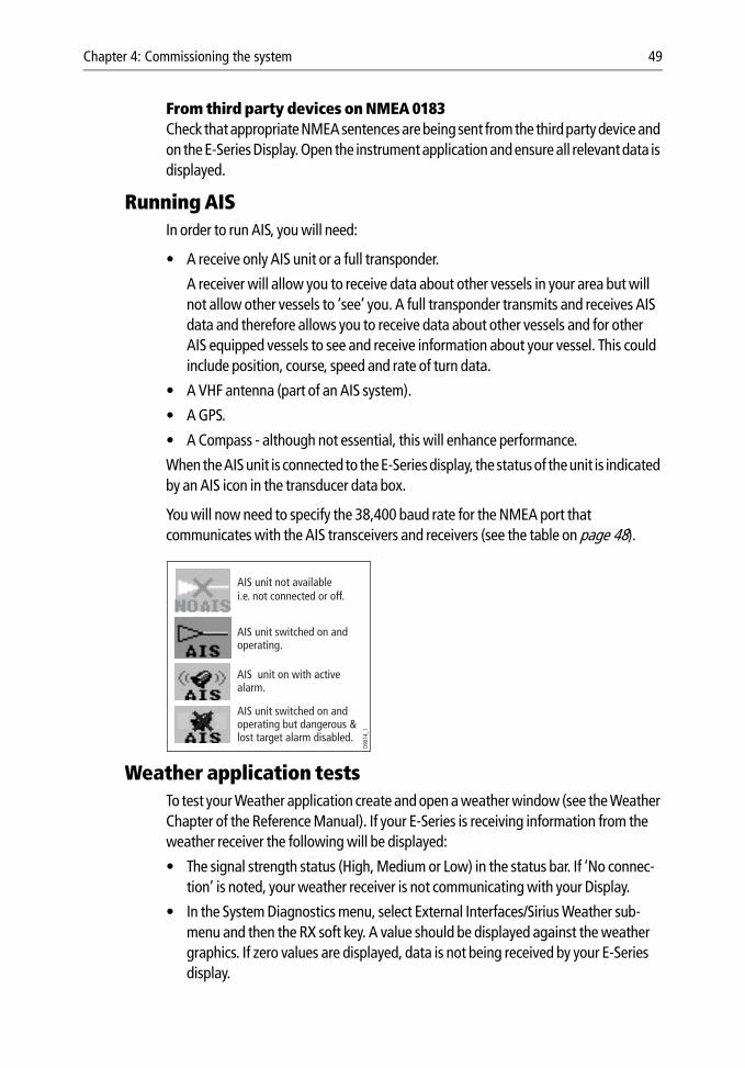
AIS unit not available i.e. not connected or off.
AIS unit switched on and operating.
AIS unit switched on and operating but dangerous & lost target alarm disabled.
AIS unit on with active alarm.
50 E-Series Installation Manual
4.5 Advanced Settings (analogue radar)The Advanced Set Up features allow you to set the values for the following parameters that affect the fine tuning of your radar:
Note: Under normal circumstances you will not need to adjust these settings, as they are set automatically at the factory. If these parameters are set incorrectly the performance of the ra-dar will be adversely affected.
Adjusting the settingsYou can adjust the advanced settings as follows:
1. Press MENU. The Set Up menu is displayed.
2. Use the trackpad up/down to highlight RADAR SET UP.3. Press > on the directional trackpad to select the desired options4. Use the trackpad up/down to highlight RADAR ADVANCED SET UP. 5. Press > on the directional trackpad to select the desired options.6. Press the corresponding soft key for the parameter you wish to adjust. The soft key
label is highlighted.7. Use the rotary control to adjust the parameter value in the box above the soft key.8. Press OK or use the rotary end push to accept the adjustment.9. Repeat steps 5 through 7 to adjust next parameter.
The new settings will be retained by the display and be used the next time you power up the radar.
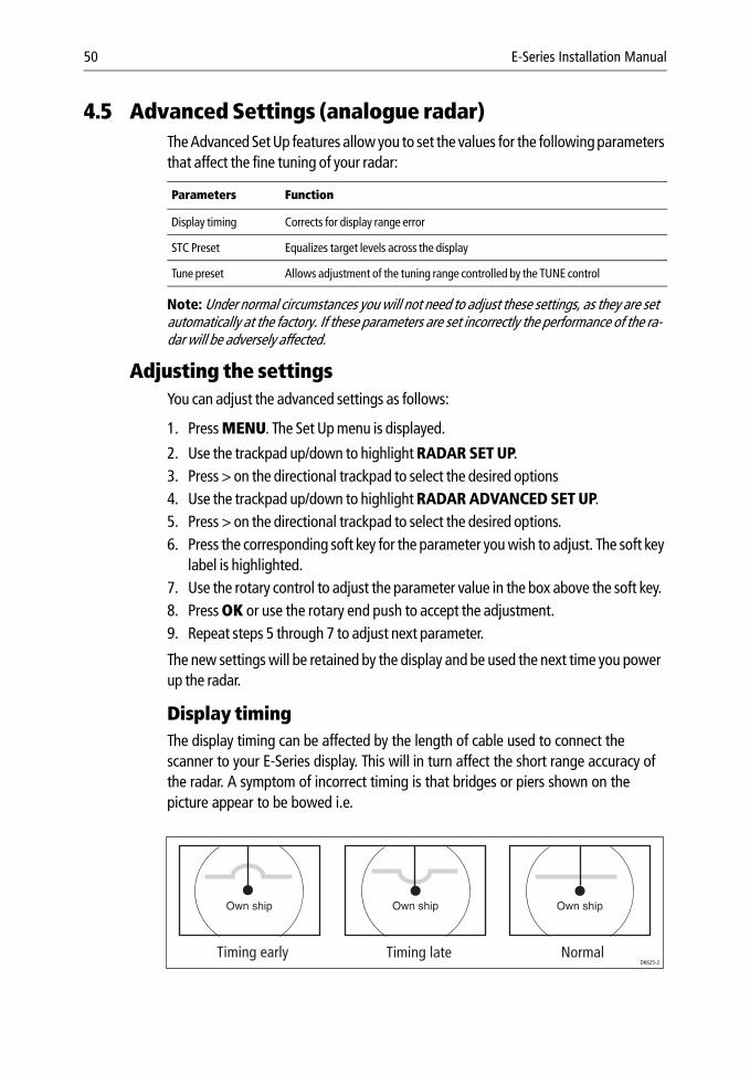
Display timing The display timing can be affected by the length of cable used to connect the scanner to your E-Series display. This will in turn affect the short range accuracy of the radar. A symptom of incorrect timing is that bridges or piers shown on the picture appear to be bowed i.e.
Parameters Function
Display timing Corrects for display range error
STC Preset Equalizes target levels across the display
Tune preset Allows adjustment of the tuning range controlled by the TUNE control
Own ship Own ship
Timing early Timing late Normal
Own ship
D6625-2
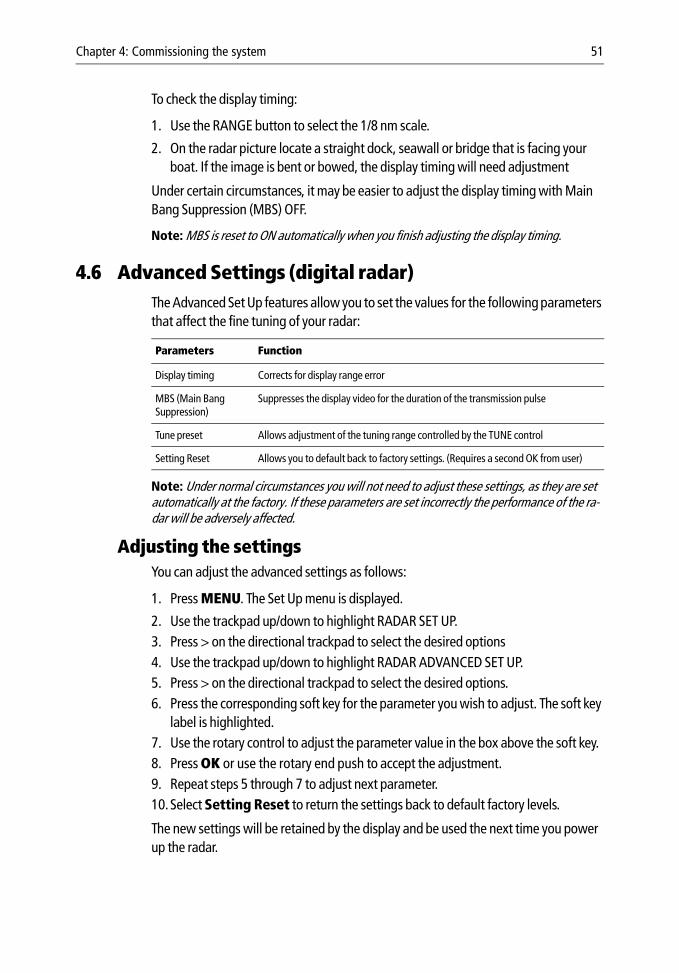
Chapter 4: Commissioning the system 51
To check the display timing:
1. Use the RANGE button to select the 1/8 nm scale.
2. On the radar picture locate a straight dock, seawall or bridge that is facing your boat. If the image is bent or bowed, the display timing will need adjustment
Under certain circumstances, it may be easier to adjust the display timing with Main Bang Suppression (MBS) OFF.
Note: MBS is reset to ON automatically when you finish adjusting the display timing.
4.6 Advanced Settings (digital radar)The Advanced Set Up features allow you to set the values for the following parameters that affect the fine tuning of your radar:
Note: Under normal circumstances you will not need to adjust these settings, as they are set automatically at the factory. If these parameters are set incorrectly the performance of the ra-dar will be adversely affected.
Adjusting the settingsYou can adjust the advanced settings as follows:
1. Press MENU. The Set Up menu is displayed.
2. Use the trackpad up/down to highlight RADAR SET UP.3. Press > on the directional trackpad to select the desired options4. Use the trackpad up/down to highlight RADAR ADVANCED SET UP. 5. Press > on the directional trackpad to select the desired options.6. Press the corresponding soft key for the parameter you wish to adjust. The soft key
label is highlighted.7. Use the rotary control to adjust the parameter value in the box above the soft key.8. Press OK or use the rotary end push to accept the adjustment.9. Repeat steps 5 through 7 to adjust next parameter.10.Select Setting Reset to return the settings back to default factory levels.
The new settings will be retained by the display and be used the next time you power up the radar.
Parameters Function
Display timing Corrects for display range error
MBS (Main Bang Suppression)
Suppresses the display video for the duration of the transmission pulse
Tune preset Allows adjustment of the tuning range controlled by the TUNE control
Setting Reset Allows you to default back to factory settings. (Requires a second OK from user)
52 E-Series Installation Manual
Display timing The display timing can be affected by the length of cable used to connect the scanner to your E-Series display. This will in turn affect the short range accuracy of the radar. A symptom of incorrect timing is that bridges or piers shown on the picture appear to be bowed i.e.
To check the display timing:
1. Use the RANGE button to select the 1/8 nm scale.
2. On the radar picture locate a straight dock, seawall or bridge that is facing your boat. If the image is bent or bowed, the display timing will need adjustment
Under certain circumstances, it may be easier to adjust the display timing with Main Bang Suppression (MBS) OFF.
Note: MBS is reset to ON automatically when you finish adjusting the display timing.
Own ship Own ship
Timing early Timing late Normal
Own ship
D6625-2
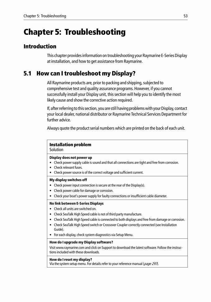
Chapter 5: Troubleshooting 53
Chapter 5: Troubleshooting
IntroductionThis chapter provides information on troubleshooting your Raymarine E-Series Display at installation, and how to get assistance from Raymarine.
5.1 How can I troubleshoot my Display?All Raymarine products are, prior to packing and shipping, subjected to comprehensive test and quality assurance programs. However, if you cannot successfully install your Display unit, this section will help you to identify the most likely cause and show the corrective action required.
If, after referring to this section, you are still having problems with your Display, contact your local dealer, national distributor or Raymarine Technical Services Department for further advice.
Always quote the product serial numbers which are printed on the back of each unit.
Installation problemSolution
Display does not power up• Check power supply cable is sound and that all connections are tight and free from corrosion.• Check relevant fuses.• Check power source is of the correct voltage and sufficient current.
My display switches off• Check power input connection is secure at the rear of the Display(s).• Check power cable for damage or corrosion.• Check your boat’s power supply for faulty connections or insufficient cable diameter.
No link between E-Series Displays• Check all units are switched on.• Check SeaTalk High Speed cable is not of third party manufacture.• Check SeaTalk High Speed cable is connected to both displays and free from damage or corrosion.• Check SeaTalk High Speed switch or Crossover Coupler correctly connected (see Installation
Guide).• For each display, check system diagnostics via Setup Menu.
How do I upgrade my Display software?Visit www.raymarine.com and click on Support to download the latest software. Follow the instruc-tions included with these downloads.
How do I reset my display?Via the system setup menu. For details refer to your reference manual (page 297).
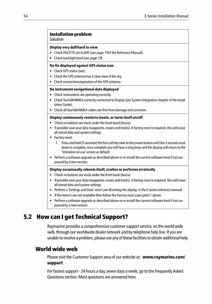
54 E-Series Installation Manual
5.2 How can I get Technical Support?Raymarine provides a comprehensive customer support service, on the world wide web, through our worldwide dealer network and by telephone help line. If you are unable to resolve a problem, please use any of these facilities to obtain additional help.
World wide webPlease visit the Customer Support area of our website at: www.raymarine.com/support
For fastest support - 24 hours a day, seven days a week; go to the Frequently Asked Questions section. Most questions are answered here.
Display very dull/hard to view• Check PALETTE set to DAY (see page 19 of the Reference Manual).• Check backlight level (see page 19).
No fix displayed against GPS status icon• Check GPS status (see).• Check the GPS antenna has a clear view of the sky.• Check connections/operation of the GPS antenna.
No instrument navigational data displayed• Check instruments are operating correctly.• Check SeaTalk/NMEA correctly connected to Display (see System Integration chapter of the Instal-
lation Guide).• Check all SeaTalk/NMEA cables are free from damage and corrosion.
Display continuously resets/re-boots, or turns itself on/off• Check no buttons are stuck under the front bezel (fascia)• If possible save your data (waypoints, routes and tracks). A factory reset is required, this will erase
all stored data and system settings• Factory reset:
1. Press and hold (5 seconds) the first soft key next to the power button until the 3 second count down is complete, once complete you will hear a long beep and the display will return to the ‘limitation on use’ screen as default.
• Perform a software upgrade as described above or re-install the current software level if not sur-passed by a new version.
Display occasionally reboots itself, crashes or performs erratically• Check no buttons are stuck under the front bezel (fascia)• If possible save your data (waypoints, routes and tracks). A factory reset is required, this will erase
all stored data and system settings• Perform a ‘Settings and Data’ reset (see Resetting the display, in the E-series reference manual)• If the menu’s are not available then follow the Factory reset a per point 1 above.• Perform a software upgrade as described above or re-install the current software level if not sur-
passed by a new version.
Installation problemSolution

Chapter 5: Troubleshooting 55
The website will also give you servicing information, e-mail access to the Raymarine Technical Support Department and details of the locations of Raymarine agents, worldwide.
If you don’t have access to the world wide web, contact Technical Support where specialists are available to answer questions about installing, operating and trouble-shooting all Raymarine products.
Help us to help youWhen requesting service, please quote the following product information:
• Equipment type.
• Model number.
• Serial number.
• Software issue number
To access this information:
1. Press MENU.
2. Highlight and select System Diagnostics.
3. Highlight and select Software Services.
4. Highlight and select Unit Info. The Unit Info: Software Details screen is displayed giving full details of your particular unit together with its software.
How can I contact Raymarine in the US?You can contact Raymarine in the US either using the Raymarine world wide web as detailed above or by calling one of the telephone numbers below.
Who do I contact for accessories and parts?You can obtain many Raymarine accessories and parts directly from your authorized Raymarine dealer. However, if your dealer does not have the item you want, contact Raymarine Technical Services at:
603 - 881 - 5200
You can use these numbers Monday through Friday 0815to 1700 Eastern Standard Time or Eastern Daylight Savings Time.
If you are not sure which item is appropriate for your unit, you should first contact the Technical Support Department to verify your requirements:
603 -881 - 5200
56 E-Series Installation Manual
Who do I contact for product repair and service?In the unlikely event that your Raymarine unit should develop a problem, contact your authorized Raymarine dealer for assistance. The dealer is best equipped to handle your service requirements and can offer timesaving help in getting your equipment back into normal operation.
If repairs cannot be obtained conveniently, obtain product service by returning the unit to:
Raymarine Inc.21 Manchester StreetMerrimack, NH03054 - 4801US603 -881 - 5200
The Product Repair Center is open Monday through Friday 0815 to 1700 Eastern Standard Time or Eastern Daylight Savings Time.
All products returned to the Repair Center are registered upon receipt and a confirmation letter is sent to acknowledge the repair status and the reference number of the product.
We will make every effort to carry out the repair and return your unit as quickly as possible.
If you wish to enquire about the repair status of your unit, contact the Repair Center at:
603 -881 - 5200
How can I contact Raymarine in Europe?You can obtain Technical Support, service and accessories from your authorized Raymarine dealer, or by contacting:
Raymarine UK Limited
Anchorage Park
Portsmouth, Hants
England PO3 5TD
Tel +44 (0)23 9271 4713
Fax +44 (0)23 9269 4642