Embed Size (px)
Citation preview

This hybrid regulator combinesa regulator and a solenoid valve.
Stepless control through electric signals
Simple circuit configuration
Port sizes M5 to 2 inches can be covered by combiningan ultra-compact electro-pneumatic pilot valve and a 3port high-capacity exhaust main regulator.
Ease of handling
Manifold capable
VY2Maximum operating pressure: 0.7 MPaPower consumption: 0.8 WOperating time (Estimated service life): 7000 Hr [Ultra dries air (Dew point –40°C or equivalent)]
Made to Order VY1Maximum operating pressure: 0.9 MPaPower consumption: 1.8 WOperating time (Estimated service life): 3000 Hr [Ultra dries air (Dew point –40°C or equivalent)]
VY2D00 VY2400
E-P HYREG ®
3(R)
2(A) 1(P)
3(R)
2(A) 1(P)
3(R)
2(A) 1(P)
3(R)
2(A)
1(P)
3(R)2(A)
1(P)
3(R)2(A)
1(P)
3(R)2(A)
1(P)
3(R)
2(A)
1(P)
3(R)
2(A)1(P)
Having the amplifier built into the electro-pneumatic pilot valve, only an external power supply and signal (voltage, current) need to be connected.
Using the VVEXB/2/4 series, a maximum 10 station manifold is possible.
Piping labor reducedA flexible system has been adopted.
Application exampleCapable of performing multistage pressure control and stepless pressure control by varying the electrical
Cylinder Thrust Control
Drive and Thrust Control
Flow Control of Various Fluids
Pressure Control of Tank
Air Flow Control of Nozzle Note)Tension controlbalancer
Cylinder behavior and pressurization controlfor peeningand stamping
For remote control ofanother air operated valve
Automatic adjustments
Air blowingAir cooling
Example
Welding pressure control of spot welding gun cylinder Loading cylinder control
ExampleAuto balancer
Simplified main circuit
Simplified pilot circuit
Long service life and low wattage type as standard
Nozzle
Note) Use for the sonic flow.
E-P HYREG®
Series VY2
713
ARJ
AMR
ARM
ARP
IR
IRV
VEX1�
SRH
SRP
SRF
ARX20
VCHR
ITV
IC
PVQ
VER
VEA
VY2
AP100
VBAVBAT
AR425to 935
VEFVEP
P0675-P0758-E.qxd 08.11.7 10:40 AM Page 713
Courtesy of Steven Engineering, Inc.-230 Ryan Way, South San Francisco, CA 94080-6370-Main Office: (650) 588-9200-Outside Local Area: (800) 258-9200-www.stevenengineering.com

NilFNT
VY2D00-�00 (3)
VY2B00-�00 (3)
D
B
2
4
A
1
3
5
7
9
Port 1(P), 2(A) Port 3(R)00M500M50100010200020304M5010202030404061010121420
RcG
NPTNPTF
Applicable pilot valve (2)
01 010VY2
Maximum operating pressure:0.7MPa
01
24 V
12 V
1 0 to 7.5 VNil 1 to 4 V
2 4 to 16 mA3 0 to 15 mA5 1 to 4 V6 0 to 7.5 V7 4 to 16 mA8 0 to 15 mA
10 kΩ67 kΩ
120 Ω
67 kΩ10 kΩ
120 Ω
3(R)
2(A)1(P)
3(R)
2(A)1(P)
P1
Made to Order(Refer to pages 730 to 735 for details.)
Maximum operating pressure: 0.9 MPa (VY1)
Note 1) Only bracket or foot may be mounted. Note 2) When replacing the pilot valve, it may not satisfy characteristics such as accuracy, etc. Confirm the
product works under the operating conditions before using. If SMC is requested to repair the product, SMC confirms whether characteristics are satisfied.
Note 3) � in the applicable pilot valve part number is designated for the power source/command signal.
How to Order
E-P HYREG® Pilot typeInternal pilotExternal pilot Note)
Thread type
Power source/Command signalSymbol Power source voltage DC Command signal DC Input impedance
JIS Symbol
Internal pilot
External pilot
Body size Port size Rc OptionMounting
Base mounted
Body ported
Symbol Symbol B (Bracket) F (Foot) G (Pressure gauge) N (Silencer)Without sub-plate
M5Without sub-plate
M5
Without sub-plate
Without sub-plate
M5
1
18
18
14
14
38
12
18
14
14
38
12
12
34
1
22
114
112
114
(1) (1)
(1) (1)
Note) Except body size D
714
Series VY2
P0675-P0758-E.qxd 08.11.7 10:40 AM Page 714
Courtesy of Steven Engineering, Inc.-230 Ryan Way, South San Francisco, CA 94080-6370-Main Office: (650) 588-9200-Outside Local Area: (800) 258-9200-www.stevenengineering.com

SpecificationsVY2D00
M51(P)2(A)3(R)
M5
0.110.009 MPa0.005 MPa± 0.005 MPa
10 ms
0.027 MPa0.014 MPa± 0.009 MPa
0.023 MPa0.009 MPa
± 0.009 MPa
0.045 MPa0.018 MPa
± 0.018 MPa
VY2A0 VY2B0 M5
M5
0.16
M5 01
M5
0.19 0.25 0.35 0.55 0.75 1.5 2 4
01 VY210
01 02
01
01
18
18
14
VY220 01 02
01
18
14
VY230 02 03
01
14
38
04
12
02 03
14
38
04
12
04 06
12
34 1 1
10 12
14
1
10
1
14
VY240 01 VY250 01 VY270 0120
22
14
112
VY290 01
VY250 VY2B0 VY2A0
BFGN AN120-M5
VEXA-18-2AVEXA-18-3A
G27-10-R1-X207
VEX1-18-1AVEX1-18-2A
G27-10-01AN120-M5
VEX3-32A
G36-10-01AN101-01 AN120-M5
VEX5-32A VEX7-32A
G46-10-01AN210-02
VEX9-32A
01
01 VY210 01 VY220 01 VY230 01
01
01VY240 VY270 01 VY290 01VY2D00
– (Direct operated)
VEXB-2-2 P
Sub-plate and Base Gasket Part No.Valve size D B
Sub-plate
Base gasket
(Port size: M5)
VEXD-5
VEXD-7 VEXB-4-1
SymbolAB
Port sizeM51
8
SymbolNilFNT
Thread typeRcG
NPTNPTF
VEX1-9-1 P
2 4
VEX1-11-2 VEX4-4
SymbolAB
18
14
SymbolNilFNT
Thread typeRcG
NPTNPTF
VEX4-2A- P
SymbolABC
14
38
SymbolNilFNT
Thread typeRcG
NPTNPTF
12
Thread type
Thread type Thread type
Note 1) The mass of the base mounting type (D/B/2/4 size) with sub-plate is indicated.Note 2) All property values indicate maximum values. Note 3) Supply pressure must be 0.7 MPa or less. When the supply pressure exceeds 0.7 MPa, it may cause abnormal leakage from the pilot valve or abnormal set pressure. Note 4) The command signal should not fall in the area A (broken line section) in Signal – Outlet Pressure Characteristics on page 716. When setting a pressure with a command signal, it must be (supply air –0.04 MPa) or less. If the pressure falls in the area A or set pressure exceeds
(supply air –0.04 MPa), the pilot valve will be ON (open). Note that if the supply pressure changes under this circumstance, the set pressure also changes.
Note 5) Cut off the command signal when the pressure control on the outlet side is not required, such as when the line is temporarily halted, etc. Refer to Specific Product Precautions on page 736.
Note 6) To lubricate the outlet side of “VY”, use “VY” as an external pilot. Avoid lubrication to the pilot air.Note 7) The non-lubricated specification is not applicable to these models.Note 8) The maximum operating pressure of 0.9 MPa is available as a made-to-order specification. Refer to pages 730 to 735 for details.
Port size
Model
Fluid
Ambient and fluid temperature
Maximum operating pressure
Regulating pressure range
External pilot pressure
Command signal (5)
Power supply
Electrical entry
Applicable cable
Bleed air flow (Port P2)
Installation
Lubrication
Mass (kg) (1)
Hysteresis (2)
Sensitivity (2)
Repeatability (2)
Response time (2)
Port
30 ms
Air
0.05 to 0.66 MPa (Supply pressure 0.7 MPa) (4)
0.7 MPa (3), (8)
0 to 50°C (No condensation)
Set pressure +0.04 MPa to 0.7 MPa (VY2�01)
1 to 4 VDC, 0 to 7.5 VDC, 4 to 16 mA DC, 0 to 15 mA DC
12 VDC ± 10%, 24 VDC ± 10%, 0.8 W or less
DIN terminal
Cable O.D. ø4 to 6.5
When not operating: Zero, When operating: 7 l/min (ANR) (Supply pressure 0.7 MPa)
Universal
Not required (6), (7)
OptionPart no.
Description
Bracket (With bolt, washer)
Pressure gauge
Pilot EXH port silencer
Port sizePort size
Port sizePort size
Port size
Valve size
Sub-plate
Base gasket
715
E-P HYREG Series VY2R
ARJ
AMR
ARM
ARP
IR
IRV
VEX1�
SRH
SRP
SRF
ARX20
VCHR
ITV
IC
PVQ
VER
VEA
VY2
AP100
VBAVBAT
AR425to 935
VEFVEP
P0675-P0758-E.qxd 08.11.7 10:40 AM Page 715
Courtesy of Steven Engineering, Inc.-230 Ryan Way, South San Francisco, CA 94080-6370-Main Office: (650) 588-9200-Outside Local Area: (800) 258-9200-www.stevenengineering.com

Command Signal— Outlet Pressure Characteristics (Characteristics of pressure setting)
VY2D001
0.9
0.8
0.7
0.6
0.5
0.4
0.3
0.2
0.1
Por
t 2 (
A)
pres
sure
(M
Pa)
0 1 2 3 4 5
0 2.5 5 7.5 10
VY2D00-5�
VY2D00-7�
VY2D00-6�
VY2D00-8� 0 5 10 15 20
40 8 12 16 20
V
V
mA
mA
Command signal
1
2
3
VY2A0 /VY2B01
0.9
0.8
0.7
0.6
0.5
0.4
0.3
0.2
0.1
Por
t 2 (
A)
pres
sure
(M
Pa)
0 1 2 3 4 5
0 2.5 5 7.5 10
VY2B0�-5�
VY2B0�-7�
VY2B0�-6�
VY2B0�-8� 0 5 10 15 20
40 8 12 16 20
V
V
mA
mA
Command signal
1
A
A
A
A
2
3
1
0.9
0.8
0.7
0.6
0.5
0.4
0.3
0.2
0.1
Por
t 2 (
A)
pres
sure
(M
Pa)
0 1 2 3 4 5
0 2.5 5 7.5 10
VY220�-5�
VY220�-7�
VY220�-6�
VY220�-8� 0 5 10 15 20
40 8 12 16 20
V
V
mA
mA
Command signal
1
1 1
1
1
2
3
1
0.9
0.8
0.7
0.6
0.5
0.4
0.3
0.2
0.1
Por
t 2 (
A)
pres
sure
(M
Pa)
0 1 2 3 4 5
0 2.5 5 7.5 10
VY230�-5�
VY230�-7�
VY230�-6�
VY230�-8� 0 5 10 15 20
40 8 12 16 20
V
V
mA
mA
Command signal
1
2
3
1
0.9
0.8
0.7
0.6
0.5
0.4
0.3
0.2
0.1
Por
t 2 (
A)
pres
sure
(M
Pa)
0 1 2 3 4 5
0 2.5 5 7.5 10
VY240�-5�
VY240�-7�
VY240�-6�
VY240�-8� 0 5 10 15 20
40 8 12 16 20
V
V
mA
mA
Command signal
1
2
3
1
0.9
0.8
0.7
0.6
0.5
0.4
0.3
0.2
0.1
Por
t 2 (
A)
pres
sure
(M
Pa)
0 1 2 3 4 5
0 2.5 5 7.5 10
VY270�-5�
VY270�-7�
VY270�-6�
VY270�-8� 0 5 10 15 20
40 8 12 16 20
V
V
mA
mA
Command signal
1
2
3
1
0.9
0.8
0.7
0.6
0.5
0.4
0.3
0.2
0.1
Por
t 2 (
A)
pres
sure
(M
Pa)
0 1 2 3 4 5
0 2.5 5 7.5 10
VY290�-5�
VY290�-7�
VY290�-6�
VY290�-8� 0 5 10 15 20
40 8 12 16 20
V
V
mA
mA
Command signal
1
2
3
1
0.9
0.8
0.7
0.6
0.5
0.4
0.3
0.2
0.1
Por
t 2 (
A)
pres
sure
(M
Pa)
0 1 2 3 4 5
0 2.5 5 7.5 10
VY250�-5�
VY250�-7�
VY250�-6�
VY250�-8� 0 5 10 15 20
40 8 12 16 20
V
V
mA
mA
Command signal
1
2
3
VY210 /VY220
Command signal voltage (current) for starting the operation of a pilot valve VY2D0 (direct operated)(There is dispersion in the following range.)
Symbol (1)
Nil, 51, 62, 73, 8
Command Signal Operation start range0.93 to 1.07 V DC0.01 to 0.1 V DC3.7 to 4.3 mA DC0.02 to 0.2 mA DC
1 to 4 V DC0 to 7.5 V DC4 to 16 mA DC0 to 15 mA DC
VY270 VY290
VY250VY240VY230
01
01
01
01
01
01
01
01
01
Note 1) Enter symbols above � in VY2D0∗-�∗∗. � indicates power supply and a command signal.
Note 2) Other body sizes add the dispersion on the above data when the main valve activates.
When setting a pressure with a commandNote 1) Supply pressure must be 0.7 MPa or less.
When the supply pressure exceeds 0.7 MPa, it may cause abnormal leakage from the pilot valve or abnormal set pressure.
Note 2) The command signal should not fall in the area A (broken line section) in Signal – Outlet Pressure Characteristics. When setting a pressure with a command signal, it must be (supply air – 0.04 MPa) or less. If the pressure falls in the area A or set pressure exceeds (supply air – 0.04 MPa), the pilot valve will be ON (open). Note that if the supply pressure changes under this circumstance, the set pressure also changes.
A A A
AAA
A A
Port 1 (P) pressure 0.7 MPa
∗
Characteristics
716
Series VY2
P0675-P0758-E.qxd 08.11.7 10:40 AM Page 716
Courtesy of Steven Engineering, Inc.-230 Ryan Way, South San Francisco, CA 94080-6370-Main Office: (650) 588-9200-Outside Local Area: (800) 258-9200-www.stevenengineering.com

Set point
Set point
Set point
Set pointSet point
Set point
Set point
Set point
VY2D00 VY2A0 /2B001
01
VY230 01VY210 /2200
101
VY240 01 VY250 0
1
VY290 01VY270 0
1
Pressure Characteristics
Port 1 (P) pressure (MPa)
Por
t 2 (
A)
pres
sure
(M
Pa)
Port 1 (P) pressure (MPa)
Por
t 2 (
A)
pres
sure
(M
Pa)
Port 1 (P) pressure (MPa)
Por
t 2 (
A)
pres
sure
(M
Pa)
Port 1 (P) pressure (MPa)
Por
t 2 (
A)
pres
sure
(M
Pa)
Port 1 (P) pressure (MPa)
Por
t 2 (
A)
pres
sure
(M
Pa)
Port 1 (P) pressure (MPa)
Por
t 2 (
A)
pres
sure
(M
Pa)
Port 1 (P) pressure (MPa)
Por
t 2 (
A)
pres
sure
(M
Pa)
Port 1 (P) pressure (MPa)
Por
t 2 (
A)
pres
sure
(M
Pa)
717
E-P HYREG R Series VY2
ARJ
AMR
ARM
ARP
IR
IRV
VEX1�
SRH
SRP
SRF
ARX20
VCHR
ITV
IC
PVQ
VER
VEA
VY2
AP100
VBAVBAT
AR425to 935
VEFVEP
P0675-P0758-E.qxd 08.11.7 10:40 AM Page 717
Courtesy of Steven Engineering, Inc.-230 Ryan Way, South San Francisco, CA 94080-6370-Main Office: (650) 588-9200-Outside Local Area: (800) 258-9200-www.stevenengineering.com

Flow Characteristics
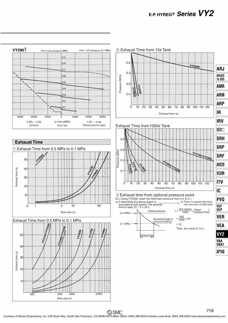
Port 2 (A) pressure MPa Port 1 (P) pressure 0.7 MPa
Port 2 (A) pressure MPa Port 1 (P) pressure 0.7 MPa
12 128 84 0 4 600 600400 400200 0 200
4000 40003000 30002000 1000 0 20001000
15000 1500010000 100005000 0 5000
1500 15001000 1000500 0 500
7500 75005000 50002500 0 2500
Port 2 (A) pressure MPa Port 1 (P) pressure 0.7 MPa
Port 2 (A) pressure MPa Port 1 (P) pressure 0.7 MPa
Port 2 (A) pressure MPa Port 1 (P) pressure 0.7 MPa
Port 2 (A) pressure MPa Port 1 (P) pressure 0.7 MPa
3 (R) 2 (A) 1 (P) 2 (A)
1 (P) 2 (A)
3 (R) 2 (A) 1 (P) 2 (A) 3 (R) 2 (A) 1 (P) 2 (A)
3 (R) 2 (A) 1 (P) 2 (A)
3 (R) 2 (A) 1 (P) 2 (A)(l / min (ANR))
Exhaust Flow rate Reduced pressure supply(l / min (ANR))
Exhaust Flow rate Reduced pressure supply
(l / min (ANR))
Exhaust Flow rate Reduced pressure supply
(l / min (ANR))
Exhaust Flow rate Reduced pressure supply3 (R) 2 (A)
(l / min (ANR))
Exhaust Flow rate Reduced pressure supply
(l / min (ANR))
Exhaust Flow rate Reduced pressure supply
VY270 01VY270 0
1
VY210 /22001
01 VY230 /2400
101
VY2A0 /2B001
01VY2D00
Characteristics
718
Series VY2
P0675-P0758-E.qxd 08.11.7 10:40 AM Page 718
Courtesy of Steven Engineering, Inc.-230 Ryan Way, South San Francisco, CA 94080-6370-Main Office: (650) 588-9200-Outside Local Area: (800) 258-9200-www.stevenengineering.com
30000 3000020000 2000010000 0 10000
VY2D00
VY
2100
/VY
2200
VY
2300
/VY
2400
VY
2500
VY
2700
VY
2900
VY
2A00
VY2B
00
VY2100/VY2200VY2300/VY2400
VY2500
VY
2700
VY
2900
VY2D00
VY
2A00
VY
2B00
VY290 01 w Exhaust Time from 10 l Tank
Pre
ssur
e (M
Pa)
Exhaust time (s)
Exhaust Time from1000 l Tank
Pre
ssur
e (M
Pa)
Exhaust time (s)
Initial pressure
Numerical target ofpressure lowering
Exhaust time
0.1 MPa0.4 MPa
0.1 MPa
eExhaust time from optional pressure pointEx.] Using VY2500, lower the 500 l tank pressure from 0.4 to 0.1.a) If describing the above graph in
accordance with graphs, the exhausttime is read; 27 – 3 = 24 s.
b) Then, to convert the timeinto one from a 500 l tank.
t =Tank capacity
1000 x Readexhaust time[ ]
=500
1000 x 24
≅ 12
Then, the result is 12 s.
Exhaust Time
Port 2 (A) pressure MPa Port 1 (P) pressure 0.7 MPa
3 (R) 2 (A) 1 (P) 2 (A)(l / min (ANR))Exhaust Flow rate Reduced pressure supply
Exh
aust
tim
e (s
)
Tank size ( l )
Exh
aust
tim
e (s
)
Tank size ( l )
q Exhaust Time from 0.5 MPa to 0.1 MPa
Exhaust Time from 0.5 MPa to 0.1 MPa
719
E-P HYREG Series VY2R
ARJ
AMR
ARM
ARP
IR
IRV
VEX1�
SRH
SRP
SRF
ARX20
VCHR
ITV
IC
PVQ
VER
VEA
VY2
AP100
VBAVBAT
AR425to 935
VEFVEP
P0675-P0758-E.qxd 08.11.7 10:40 AM Page 719
Courtesy of Steven Engineering, Inc.-230 Ryan Way, South San Francisco, CA 94080-6370-Main Office: (650) 588-9200-Outside Local Area: (800) 258-9200-www.stevenengineering.com

2 x ø4.4 Mounting hole
Port 1 (P), 2 (A), 3 (R)3 x M5
Applicable cable O.D.
All types are thesame in terms ofconnection.
Silencer (Option)
ø4 to ø6.5
Connection mark
Applicable cable O.D.ø4 to ø6.5
All types are thesame in terms ofconnection.
Connection mark
(VY2A01 only)M5 external pilot port
Hexagon socket head cap screw M3l = 8 (2 pcs.)(With spring washer)( )
VEXA-18-2ABracket (Option)
VEXA-18-3AHexagon socket head cap screw M3l = 8 (2 pcs.)(With spring washer)( )
Foot (Option)
4 x ø4.5 Mounting hole
2 x ø4.5 Mounting hole
2 x M3Bracket mountingthread
Port 1 (P), 2 (A), 3 (R)3 x M5
VY2D00
VY2A0 01
Dimensions
720
Series VY2
P0675-P0758-E.qxd 08.11.7 10:40 AM Page 720
Courtesy of Steven Engineering, Inc.-230 Ryan Way, South San Francisco, CA 94080-6370-Main Office: (650) 588-9200-Outside Local Area: (800) 258-9200-www.stevenengineering.com

1/8, 1/4
(VY2B01 only)M5 external pilot port
All types are thesame in terms ofconnection.
Connection mark2 x ø4.5Mounting hole
1/16 Gauge port
Pressure gauge (Option)
G27-10-R1-X207
Port 1 (P), 3 (R)M5, 1/8
Applicable cable O.D.ø4 to ø6.5
Port 2 (A)M5, 1/8
(VY2101 only)M5 external pilot port
All types are thesame in terms ofconnection.
Connection mark
Port 2 (A)
Mounting hole2 x ø4.5
4 x ø4.5 Mounting hole2 x M3 Bracket mounting thread
Hexagon socket head cap screw M3l = 8 (2 pcs.)(With spring washer)( )
VEX1-18-1ABracket (Option)
VEX1-18-2Hexagon socket head cap screw M3l = 8 (2 pcs.)(With spring washer)( )
Foot (Option)
Pressure gauge (Option)
G27-10-01
AN120-M5
Silencer (Option)
1/8 gauge port
Port 1 (P), 3 (R)1/8, 1/4
M5Pilot EXH port
Applicable cable O.D.ø4 to ø6.5
VY21001
VY2B001
721
E-P HYREG Series VY2R
ARJ
AMR
ARM
ARP
IR
IRV
VEX1�
SRH
SRP
SRF
ARX20
VCHR
ITV
IC
PVQ
VER
VEA
VY2
AP100
VBAVBAT
AR425to 935
VEFVEP
P0675-P0758-E.qxd 08.11.7 10:40 AM Page 721
Courtesy of Steven Engineering, Inc.-230 Ryan Way, South San Francisco, CA 94080-6370-Main Office: (650) 588-9200-Outside Local Area: (800) 258-9200-www.stevenengineering.com

1/8 Gauge port
2 x ø4.5Mounting hole
(VY2201 only)M5 external pilot port
All types are thesame in terms ofconnection.
Connection mark
Pressure gauge (Option)G27-10-01
P2 PortM5
Pilot EXH port
AN120-M5Silencer (Option)
Applicable cable O.D.ø4 to ø6.5
Port 1 (P), 2 (A), 3 (R)3 x 1/8, 1/4
Port 1 (P)1/4, 3/8, 1/2
All types are thesame in terms ofconnection.
Connection mark
Port 3 (R)1/4, 3/8, 1/2
Bracket (Option)VEX3-32AHexagon socket head cap screw M5l = 10 (4 pcs.)(With spring washer)( )
Applicable cable O.D. ø4 to ø6.5
Port 1 (P)1/4, 3/8, 1/2
1/8 Pilot EXH port
(VY2301 only)1/8 external pilot port
Mounting holeelongated
Bracket mounting thread
4 x M5
Pressure gauge (Option)G36-10-01
View A
AN101-01Silencer (Option)
1/8 Gauge port
VY22001
VY23001
Dimensions
722
Series VY2
P0675-P0758-E.qxd 08.11.7 10:40 AM Page 722
Courtesy of Steven Engineering, Inc.-230 Ryan Way, South San Francisco, CA 94080-6370-Main Office: (650) 588-9200-Outside Local Area: (800) 258-9200-www.stevenengineering.com

Port 1 (P), 3 (R)1/4, 3/8, 1/2
All types are thesame in terms ofconnection.
Connection mark
2 x ø5.5Mounting hole
M5 Pilot EXH port
AN120-M5Silencer (Option)
Port 2 (A)1/4, 3/8, 1/2
(VY2401 only)1/8 external pilot port
Applicable cable O.D.ø4 to ø6.5
View A
Pressure gauge (Option)G46-10-01
All types are the same in terms of connection.
Connection mark
Port 3 (R)1/2, 3/4, 1
1/8 Gauge port
Applicable cable O.D. ø4 to ø6.5
(VY2501 only)1/4 external pilot port
AN210-02Silencer (Option)
1/4 Pilot EXH portBracket (Option)
VEX5-32AHexagon socket head cap screw M6 l = 10 (2 pcs.)(With spring washer)( )
Bracket mounting thread
2 x M6
Port 1 (P), 2 (A)2 x 1/2, 3/4, 1
View A
2 x ø9Mounting hole
VY25001
VY24001
723
E-P HYREG Series VY2R
ARJ
AMR
ARM
ARP
IR
IRV
VEX1�
SRH
SRP
SRF
ARX20
VCHR
ITV
IC
PVQ
VER
VEA
VY2
AP100
VBAVBAT
AR425to 935
VEFVEP
P0675-P0758-E.qxd 08.11.7 10:40 AM Page 723
Courtesy of Steven Engineering, Inc.-230 Ryan Way, South San Francisco, CA 94080-6370-Main Office: (650) 588-9200-Outside Local Area: (800) 258-9200-www.stevenengineering.com

All types are thesame in terms ofconnection.
Connection markPressure gauge (Option)G46-10-01
Applicable cable O.D.ø4 to ø6.5
Port 3 (R)1, 1/4
1/8 Gauge port
VY27001
VY29001
Dimensions
724
(VY2701 only)1/4 external pilot port
Port 1 (P), 2 (A)2 x 1, 1 1/4
AN210-02Silencer (Option)
1/4 Pilot EXH port
Bracket mounting thread
4 x M6
2 x ø9Mounting hole
View A
Bracket (Option)VEX7-32AHexagon socket head cap screw M6l = 10 (4 pcs.) (With spring washer)( )
Pressure gauge (Option)G46-10-01
All types are thesame in terms ofconnection.
Connection mark
1/8 Gauge port
Applicable cable O.D.ø4 to ø6.5
Port 3 (R)
Port 1 (P), 2 (A)2 x 1 1/2, 2
(VY2901 only)1/4 external pilot port
AN210-02Silencer (Option)
1/4 Pilot EXH port
Bracket mounting thread4 x M6
4 x ø7Mounting holeBracket (Option)VEX9-32A
Hexagon socket head cap screw M6 l = 15 (4 pcs.)(With spring washer)( )
View A
( )
Pg.7
Series VY2
P0675-P0758-E.qxd 08.11.7 10:40 AM Page 724
Courtesy of Steven Engineering, Inc.-230 Ryan Way, South San Francisco, CA 94080-6370-Main Office: (650) 588-9200-Outside Local Area: (800) 258-9200-www.stevenengineering.com

725
ARJ
AMR
ARM
ARP
IR
IRV
VEX1�
SRH
SRP
SRF
ARX20
VCHR
ITV
IC
PVQ
VER
VEA
VY2
AP100
VBAVBAT
AR425to 935
VEFVEP
P0675-P0758-E.qxd 08.11.7 10:40 AM Page 725
Courtesy of Steven Engineering, Inc.-230 Ryan Way, South San Francisco, CA 94080-6370-Main Office: (650) 588-9200-Outside Local Area: (800) 258-9200-www.stevenengineering.com

1
2
3
4
5
6
7
8
3(R)1(P) 2(A)
3(R)
1(P)
2
(A)
VY2A001, VY2B00
1 (Pilot valve: VY2D00-�00)
Solenoid valveControl
circuit
Cover
Body
Pressure sensor
Feedbackpassage
Sub-plate
Power supply
Commandsignal
Connection markAll types are the samein terms of connection.
Port P1
Feedback passage
Sub-plate
The VY2D00, which is the smallest direct drive, consists of a solenoid, pressure sensor, control circuit, body cover, and a sub plate. The type with sub-plate can be used alone, and the type without sub-plate can also be used as a pilot valve.
Circuit
Power supplyInput signal
Solenoid valve
Control circuitPressuresensor
Working principle� When the command signal is below 1 VDC,
(refer to page 716) the solenoid valve is inactive, and the port 2(A) pressure is zero.
� When a command signal between 1 and 5 VDC is provided, the solenoid is activated.
� The port 2(A) pressure is fed back to the control circuit by the pressure sensor.
� The control circuit compares the feedback signal with the size of the command signal that was provided, and:1) If the feedback signal is smaller, current
is supplied to the solenoid valve to raise the port 2(A) pressure [from 1(P) to 2(A)].
2) If the feedback signal is greater, current is not supplied to valve to reduce the port 2(A) pressure [from 2(A) to 3(R)].
The above processes 1) and 2) are repeated at high speeds to set the port 2(A) pressure.
Component PartsDescription Material
Body
Pilot valve assembly
Adjusting piston
Spring
Valve guide
Valve
Retainer
Rod
Zinc alloy die-casted
—
Aluminum alloy
Stainless steel
Stainless steel
Aluminum alloy/Rubber
Aluminum alloy
Stainless steel/Rubber
Working principle� The supply [1(P) to 2(A)] valve of valve y
and the exhaust [2(A) to 3(R)] valve close due to the balance between actuating forces F1 and F2. Actuating force F1 is applied to the right surface of pressure regulation piston e by the pilot pressure (pilot valve assembly w: VY2D00-�00), and actuating force F2 is applied to the left surface of the pressure regulation piston by the port and pressure that passes through the feedback passage. Thus, the port 2(A) pressure that coprresponds to the pilot pressure is established.
� When the port 2(A) pressure becomes higher than the pilot pressure, F2 becomes greater than F1. This causes only the pressure regulation piston to move to the right, and the exhaust valve seat to open, allowing the air to be discharged from port 2(A) to port 3(R). When the port 2(A) pressure drops to reach a balance, the regulator returns to the set state.
� Conversely, if the port 2(A) pressure is lower than the pilot pressure, F2 becomes lower than F1. This causes the pressure regulating piston to move the valve to the left, and the supply valve seat to open, allowing the air to be supplied from port 1(P) to port 2(A). When the port 2(A) pressure balances, the regulator reuturns to the set state.
726
Series VY2
Construction/Component Parts/Working Principle
VY2D00
P0675-P0758-E.qxd 08.11.7 10:40 AM Page 726
Courtesy of Steven Engineering, Inc.-230 Ryan Way, South San Francisco, CA 94080-6370-Main Office: (650) 588-9200-Outside Local Area: (800) 258-9200-www.stevenengineering.com

1
2
3
4
5
6
7
8
9
Port 2(A) Port 1(P)
Port 3(R)
Feedback passage
P1 port
Working principle� The pair of poppet valves u close due to the
balance between actuating forces F1 and F2. Actuating force F1 is applied to the top surface of pressure regulation piston r by the pilot pressure (pilot valve assembly q: VY2D
B 00-00), and actuating force F2 is applied to the bottom surface of the piston by the port 2(A) pressure that pases through the feedback passage. Thus, the port 2(A) pressure that corresponds to the pilot pressure is established. The poppet valve, which maintains a pressure balance with the port 2(A) pressure, is backed up by spring t (refer to the diagram on the left).
� When the port 2(A) pressure becomes higher than the pilot pressure, F2 becomes higher than F1. This causes the pressure regulation piston to move upward, and the top poppet valve to open, allowing the air to be discharged from port 2(A) to port 3(R). When the port 2(A) pressure drops to reach a balance, the regulator returns to the state shown in the diagram to the left.
� Conversely, if the port 2(A) pressure is lower than the pilot pressure, F2 becomes less than F1. This causes the pressure regulation piston to move downward, and the lower poppet valve to open, allowing the air to be supplied from port 1(P) to port 2(A). When the port 2(A) pressure rises to reach a balance, the regulator returns to the state shown in the diagram to the left.
Component PartsNo. Material
—Pilot valve assembly
Body
Cover
Adjusting piston
Spring
Valve guide
Poppet valve
Shaft
Valve guide
Aluminum alloy
Aluminum alloy
Aluminum alloy
Aluminum alloy
Aluminum alloy
Stainless steel
Stainless steel
Aluminum alloy/Rubber
Description
727
VY21001, VY2200
1, VY23001, VY2400
1 (Pilot valve: VY2D00-�00)VY2500
1, VY27001, VY2900
1 (Pilot valve: VY2B00-�00)
E-P HYREG Series VY2R
ARJ
AMR
ARM
ARP
IR
IRV
VEX1�
SRH
SRP
SRF
ARX20
VCHR
ITV
IC
PVQ
VER
VEA
VY2
AP100
VBAVBAT
AR425to 935
VEFVEP
P0675-P0758-E.qxd 08.11.7 10:40 AM Page 727
Courtesy of Steven Engineering, Inc.-230 Ryan Way, South San Francisco, CA 94080-6370-Main Office: (650) 588-9200-Outside Local Area: (800) 258-9200-www.stevenengineering.com

01
01
01VY2B0
VEXB-6 VEX1-17 VEX4-5
VY220 VY240
NPTFNPT
1(P), 3(R) 2(A)
Nil
2 3 4 5 6 7 8 9 1071.8 95.2 118.6 142 165.4 188.8 212.2 235.6 25958.8 82.2 105.6 129 152.4 175.8 199.2 222.6 246
B
2
4
1 22
T
FN
02
01
ABC
2
1
2
1
2
L1L2
2102
82
6
RcG
Pilot type Manifold base part no.Internal pilot manifoldCommon external pilot manifoldIndividual external pilot manifold
VVEX�-1-�-��VVEX�-2-�-��VVEX�-�-�-��
VY2�00
VY2�01
M51
81
4
18
14
38
14
38
38
12
14,
38,
12
BVVEX
VVEXB
1 5 01
VY manifold pilot typeBody size B, 2
Note) It is recommended to use a common type when the external pilot type is used.
Note)
Note)
Manifold SpecificationsE-P HYREG ®
VVEX4-1-�-��VVEX4-2-�-��
VY2400VY2401
Body size 4
Using the series VVEXB/2/4,a maximum of 10 stations manifold is possible.
Applicable valve
Valve stations (1) 2 to 10 stations 2 to 8 stations 2 to 6 stationsPassage
Internal pilot, Common external pilot (2)Pilot typePilot port sizePort size port 1(P), 2(A), 3(R)
Common supply/exhaust
Blanking plate assembly (3)
Specifications
Note 1) VY2B0016 stations or more, VY2200
15 stations or more, VY240014 stations or more supply pressure to
the ports 1(P) on both sides of the manifold and exhaust pressure from the port 3(R) on the both sides.
Note 2) When used as a common external pilot, select the internal pilot specification as an applicable valve. Note 3) Gasket and mounting bolts are equipped.
How to Order
Body size Pilot type Valve stations Port size
Enter the valves and the blank plates to be placed on a manifold in order, starting at the left side of the manifold base (with port 2(A) facing you).
Ex.) VVEX2-2-5-02• VY2200-00-G 4 pcs.• VEX1-17 1 pc.
Note) In the case of VVEXB, the “2” in the first digit of the valve station number is a dummy part number.
Piping thread type
01For VY2B0
01For VY220
01For VY240
Common external pilot
Internal pilot
Common external pilot
Internal pilot
Internal pilot
Common external pilot
······
···
······
···
2 stations
10 stations
2 stations
8 stations2 stations
6 stations
Connection mark
All types are the same interms of connection.
Individual external pilot port: P1M5 (VY2B01-�00 only) 2 x ø5.5
Mounting hole
Port 3(R): 2 x Rc 1/8Exhaust from the both sides for 6 stations or more.
Port 2(A): n x 1/8
Common external pilot port: See “Note for P1”.
2 x M5 (VVEXB-2-2n-01 only)
Port 1(P): 2 x 1/8 Pressurize from the both sides for 6 stations or more.
Blanking plate
StationsDimension
Note for P1Confirm internal pilot or common external pilot by checking whetherP1 has a M5 screw or not.Internal pilot··························· P1 has no M5 screw.Common external pilot···········P1 has an M5 screw.
Dimensions
Internal pilot manifoldCommon external pilot manifold
Applicable valve part no.
Manifold base part no. Applicable valve part no.Pilot type
728
P0675-P0758-E.qxd 08.11.7 10:40 AM Page 728
Courtesy of Steven Engineering, Inc.-230 Ryan Way, South San Francisco, CA 94080-6370-Main Office: (650) 588-9200-Outside Local Area: (800) 258-9200-www.stevenengineering.com

2 3 4 5 6123 169 215 261 307107 153 199 245 291
L1L2
2 3 4 5 6 7 891 122
107153 184 215 246 277
76 138 169 200 231 262L1L2
VVEX2
VVEX4
StationsDimension
StationsDimension
Connection markAll types are the samein terms of connection. Individual external pilot port: P1
2 x ø6.5Mounting hole
Blanking plate
Port 1(P): 2 x 1/4Pressurize from the both sides for 5 stations or more.
Port 3(R): 2 x 1/4Exhaust from the both sides
for 5 stations or more.
M5 (VY2201-�00 only)
Pilot EXH port: P2
Common external pilot port: See “Note for P1”.2 x M5 (VVEX2-2-n-02 only)
Connection markAll types are the samein terms of connection.
Pilot EXH port: P2
Blanking plate
2 x ø8.5Mounting hole
Port 2(A): n x 1/4, 3/8
Port 1(P): 2 x 3/8, 1/2Pressurize from the both sidesfor 4 stations or more.
Common external pilot port:See “Note for P1”.2 x M5(VVEX4-2-n-�� only)
Port 3(R): 2 x 3/8, 1/2Exhaust from the both sides
for 4 stations or more.
Confirm internal pilot or common external pilot by checking whether P1 has a M5 screw or not.Internal pilot··························· P1 has no M5 screw.Common external pilot··········· P1 has an M5 screw.
Note for P1
Confirm internal pilot or common external pilot by checking whether P1 has a M5 screw or not.Internal pilot··························· P1 has no M5 screw.Common external pilot··········· P1 has an M5 screw.
Note for P1
Port 2(A): n x 1/4
729
Dimensions
E-P HYREG Series VY2R
ARJ
AMR
ARM
ARP
IR
IRV
VEX1�
SRH
SRP
SRF
ARX20
VCHR
ITV
IC
PVQ
VER
VEA
VY2
AP100
VBAVBAT
AR425to 935
VEFVEP
P0675-P0758-E.qxd 08.11.7 10:40 AM Page 729
Courtesy of Steven Engineering, Inc.-230 Ryan Way, South San Francisco, CA 94080-6370-Main Office: (650) 588-9200-Outside Local Area: (800) 258-9200-www.stevenengineering.com

NilFNT
VY1D00-�00 (3)
VY1B00-�00 (3)
D
B
2
4
A
1
3
5
7
9
M5
11
22
1
00M500M50100010200020304M5010202030404061010121420
RcG
NPTNPTF
01 010VY1
E-P HYREG OptionMaximum operating pressure: 0.9 MPa 0
1
18
18
14
14
38
12
18
14
14
38
12
12
34
14
1 12
1 14
Note) Except body size D
(1)
(1)
(1)
(1)
How to Order
24 V
12 V
1 0 to 10VNil 1 to 5 V
2 4 to 20 mA3 0 to 20 mA5 1 to 5 V6 0 to 10 V7 4 to 20 mA8 0 to 20 mA
10 kΩ67 kΩ
120 Ω
67 kΩ10 kΩ
120 Ω
3(R)
2(A)1(P)
3(R)
2(A)1(P)
P1
Note) Use VY2 when the maximum operating pressure is 0.7 MPa or less.
Port 1(P), 2(A) Port 3(R)
Made to Order Maximum operating pressure: 0.9 MPa (VY1)
Pilot typeInternal pilotExternal pilot Note)
Symbol Power source voltage DC Command signal DC Input impedancePower source/Command signal
Thread type
Mounting
Base mounted
Body ported
Symbol Symbol B (Bracket) F (Foot) G (Pressure gauge) N (Silencer)
Body size Port size Rc Option
Without sub-plateM5
Without sub-plateM5
Without sub-plate
Without sub-plateJIS Symbol
Note 1) Only bracket or foot may be mounted. Note 2) When replacing the pilot valve, it may not satisfy characteristics such as accuracy, etc. Confirm the
product works under the operating conditions before using. If SMC is requested to repair the product, SMC confirms whether characteristics are satisfied.
Note 3) � in the applicable pilot valve part number is designated for the power source/command signal.
Applicable pilot valve (2)
730
Series VY1
Internal pilot
External pilot
P0675-P0758-E.qxd 08.11.7 10:40 AM Page 730
Courtesy of Steven Engineering, Inc.-230 Ryan Way, South San Francisco, CA 94080-6370-Main Office: (650) 588-9200-Outside Local Area: (800) 258-9200-www.stevenengineering.com

VY1D00M5
M5
0.110.009 MPa0.005 MPa± 0.005 MPa
10 ms
0.027 MPa0.014 MPa± 0.009 MPa
0.023 MPa0.009 MPa
± 0.009 MPa
0.045 MPa0.018 MPa
± 0.018 MPa
VY1A0 VY1B0 M5
M5
0.16
M5 01
M5
0.19 0.25 0.35 0.55 0.75 1.5 2 4
01 VY110
01 02
01
01
18
18
14
VY12001 02
01
18
14
VY130 02 03
01
14
38
04
12
02 03
14
38
04
12
04 06
12
34 1 1
10 12
14
1
10
1
14
VY140 01 VY150 01 VY170 0120
22
14
112
VY190 01
VY150 VY1B0 VY1A0
BFGN AN120-M5
VEXA-18-2AVEXA-18-3A
G27-10-R1-X207
VEX1-18-1AVEX1-18-2A
G27-10-01AN120-M5
VEX3-32A
G36-10-01AN101-01 AN120-M5
VEX5-32A VEX7-32A
G46-10-01AN210-02
VEX9-32A
01
01 VY110 01 VY120 01 VY130 01
01
01VY140 VY170 01 VY190 01VY1D00
VEXB-2-2 P
D B
(Port size: M5)
VEXD-5
VEXD-7 VEXB-4-1
SymbolAB
Port sizeM51
8
SymbolNilFNT
Thread typeRcG
NPTNPTF
VEX1-9-1 P
2 4
VEX1-11-2 VEX4-4
SymbolAB
Port size1
81
4
SymbolNilFNT
Thread typeRcG
NPTNPTF
VEX4-2A- P
SymbolABC
Port size1
43
8
SymbolNilFNT
Thread typeRcG
NPTNPTF
12
Port size
Standard Specifications
Port size
Model
Fluid
Ambient and fluid temperature
Maximum operating pressure
Regulating pressure range
External pilot pressure
Command signal (4)
Power supply
Electrical entry
Applicable cable
Bleed air flow (Port P2)
Installation
Lubrication
Mass (kg) (1)
Hysteresis (2)
Sensitivity (2)
Repeatability (2)
Response time (2)
Port
1(P)
2(A)
3(R)
— (Direct operated)
30 msAir
0.05 to 0.84 MPa (Supply pressure 0.9 MPa)0.9 MPa (3)
0 to 50°C (No condensation)
Set pressure + 0.04 to 0.9 MPa (VY1�01)
1 to 5 VDC, 0 to 10 VDC, 4 to 20 mA DC, 0 to 20 mA DC
12 VDC±10%, 24 VDC ±10%, 1.8 W or lessDIN terminal
Cable O.D. ø4 to 6.5When not operating: Zero, When operating: 10 l/min (ANR) (Supply pressure 0.88 MPa)
UniversalNot required (5)
Note 1) The mass of the base mounting type (D/B/2/4 size) with sub-plate is indicated.Note 2) All property values indicate maximum values. Note 3) Use VY2 when the maximum operating pressure is 0.7 MPa or less.Note 4) Cut off the command signal when the pressure control on the outlet side is not required, such as when the line is temporarily halted, etc. Refer to Specific Product Precautions on page 736.Note 5) To lubricate the outlet side of “VY”, use “VY” as an external pilot. Avoid lubrication to the pilot air.Note 6) The non-lubricated specification is not applicable to these models. Note 7) The service life is approximately 4000 to 5000 operating hours. (When using AF + AFM) This may be approximately 3000 hours with ultra-dry air (dew point –40°C or equivalent). Note 8) Dimensions of VY1 are the same as VY2. (This is the same for manifolds.) Note 9) “How to order manifolds” is also the same as VY2.
Part no.Description
Bracket (With bolt, washer)
Pressure gauge
Pilot EXH port silencer
Option
Thread type
Port size Thread type Port size Thread type
Made to Order Maximum operating pressure: 0.9 MPa (VY1)
Sub-plate and Base Gasket Part No.Valve size
Sub-plate
Base gasket
Valve size
Sub-plate
Base gasket
731
E-P HYREG Series VY1R
ARJ
AMR
ARM
ARP
IR
IRV
VEX1�
SRH
SRP
SRF
ARX20
VCHR
ITV
IC
PVQ
VER
VEA
VY2
AP100
VBAVBAT
AR425to 935
VEFVEP
P0675-P0758-E.qxd 08.11.7 10:40 AM Page 731
Courtesy of Steven Engineering, Inc.-230 Ryan Way, South San Francisco, CA 94080-6370-Main Office: (650) 588-9200-Outside Local Area: (800) 258-9200-www.stevenengineering.com

Command Signal — Outlet Pressure Characteristics (Characteristics of pressure setting)
VY1D001
0.9
0.8
0.7
0.6
0.5
0.4
0.3
0.2
0.1
0 1 2 3 4 5
0 2.5 5 7.5 10
VY1D00-5�
VY1D00-7�VY1D00-6�
VY1D00-8� 0 5 10 15 20
40 8 12 16 20
V
V
mA
mA
1
2
3
VY1A00/1A01,VY1B00/1B011
0.9
0.8
0.7
0.6
0.5
0.4
0.3
0.2
0.1
0 1 2 3 4 5
0 2.5 5 7.5 10
VY1B0�-5�
VY1B0�-7�VY1B0�-6�
VY1B0�-8� 0 5 10 15 20
40 8 12 16 20
V
V
mA
mA
1
A
A
A
A
2
3
1
0.9
0.8
0.7
0.6
0.5
0.4
0.3
0.2
0.1
0 1 2 3 4 5
0 2.5 5 7.5 10
VY120�-5�
VY120�-7�VY120�-6�
VY120�-8� 0 5 10 15 20
40 8 12 16 20
V
V
mA
mA
1
1 1
1
1
2
3
1
0.9
0.8
0.7
0.6
0.5
0.4
0.3
0.2
0.1
0 1 2 3 4 5
0 2.5 5 7.5 10
VY130�-5�
VY130�-7�VY130�-6�
VY130�-8� 0 5 10 15 20
40 8 12 16 20
V
V
mA
mA
1
2
3
1
0.9
0.8
0.7
0.6
0.5
0.4
0.3
0.2
0.1
0 1 2 3 4 5
0 2.5 5 7.5 10
VY140�-5�
VY140�-7�VY140�-6�
VY140�-8� 0 5 10 15 20
40 8 12 16 20
V
V
mA
mA
1
2
3
1
0.9
0.8
0.7
0.6
0.5
0.4
0.3
0.2
0.1
0 1 2 3 4 5
0 2.5 5 7.5 10
VY170�-5�
VY170�-7�VY170�-6�
VY170�-8� 0 5 10 15 20
40 8 12 16 20
V
V
mA
mA
1
2
3
1
0.9
0.8
0.7
0.6
0.5
0.4
0.3
0.2
0.1
0 1 2 3 4 5
0 2.5 5 7.5 10
VY190�-5�
VY190�-7�VY190�-6�
VY190�-8� 0 5 10 15 20
40 8 12 16 20
V
V
mA
mA
1
2
3
1
0.9
0.8
0.7
0.6
0.5
0.4
0.3
0.2
0.1
0 1 2 3 4 5
0 2.5 5 7.5 10
VY150�-5�
VY150�-7�VY150�-6�
VY150�-8� 0 5 10 15 20
40 8 12 16 20
V
V
mA
mA
1
2
3
VY1100/1101,VY1200/1201
VY1700/1701 VY1900/1901
VY1500/1501VY1400/1401VY1300/1301
Note 1) Enter symbols above � in VY1D0∗-�∗∗. � indicates power supply and a command signal.
Note 2) Other body sizes add the dispersion on the above data when the main valve activates.
Nil, 51, 62, 73, 8
0.93 to 1.07 VDC0.01 to 0.1 VDC3.7 to 4.3 mA DC0.02 to 0.2 mA DC
1 to 5 VDC0 to 10 VDC4 to 20 mA DC0 to 20 mA DC
Port 1(P) Pressure 0.9 MPa
Characteristics
Por
t 2 (
A)
pres
sure
(M
Pa)
Por
t 2 (
A)
pres
sure
(M
Pa)
Por
t 2 (
A)
pres
sure
(M
Pa)
Por
t 2 (
A)
pres
sure
(M
Pa)
Por
t 2 (
A)
pres
sure
(M
Pa)
Por
t 2 (
A)
pres
sure
(M
Pa)
Por
t 2 (
A)
pres
sure
(M
Pa)
Por
t 2 (
A)
pres
sure
(M
Pa)
Command signal Command signal Command signal
Command signal Command signal
Command signal Command signal
Command signal
Command signal voltage (current) for starting the operation of a pilot valve VY1D0∗ (direct operated)(There is dispersion in the following range)
Symbol Input signal Operation start range(1)
732
Series VY1
Made to Order Maximum operating pressure: 0.9 MPa (VY1)
P0675-P0758-E.qxd 08.11.7 10:40 AM Page 732
Courtesy of Steven Engineering, Inc.-230 Ryan Way, South San Francisco, CA 94080-6370-Main Office: (650) 588-9200-Outside Local Area: (800) 258-9200-www.stevenengineering.com

Made to Order Maximum operating pressure: 0.9 MPa (VY1)
Pressure Characteristics
Por
t 2 (
A)
pres
sure
(M
Pa)
Port 1 (P) pressure (MPa)
Por
t 2 (
A)
pres
sure
(M
Pa)
Port 1 (P) pressure (MPa)
Por
t 2 (
A)
pres
sure
(M
Pa)
Port 1 (P) pressure (MPa)
Por
t 2 (
A)
pres
sure
(M
Pa)
Port 1 (P) pressure (MPa)
Por
t 2 (
A)
pres
sure
(M
Pa)
Port 1 (P) pressure (MPa)
Por
t 2 (
A)
pres
sure
(M
Pa)
Port 1 (P) pressure (MPa)
Por
t 2 (
A)
pres
sure
(M
Pa)
Port 1 (P) pressure (MPa)
Por
t 2 (
A)
pres
sure
(M
Pa)
Port 1 (P) pressure (MPa)
Set point
Set point
Set point
Set point
Set point
Set point
Set point
Set point
VY1A0 /1B001
01
01
VY1D00
VY11 /12001
01 VY130 01
VY140 01 VY150 01
VY190 01VY170
733
E-P HYREG Series VY1R
ARJ
AMR
ARM
ARP
IR
IRV
VEX1�
SRH
SRP
SRF
ARX20
VCHR
ITV
IC
PVQ
VER
VEA
VY2
AP100
VBAVBAT
AR425to 935
VEFVEP
P0675-P0758-E.qxd 08.11.7 10:40 AM Page 733
Courtesy of Steven Engineering, Inc.-230 Ryan Way, South San Francisco, CA 94080-6370-Main Office: (650) 588-9200-Outside Local Area: (800) 258-9200-www.stevenengineering.com

Made to Order Maximum operating pressure: 0.9 MPa (VY1)
Characteristics
Flow Characteristics
Port 2 (A) pressure (MPa) Port 1 (P) pressure 0.9 MPa Port 2 (A) pressure (MPa) Port 1 (P) pressure 0.9 MPa
Port 2 (A) pressure (MPa) Port 1 (P) pressure 0.9 MPa Port 2 (A) pressure (MPa) Port 1 (P) pressure 0.9 MPa
Port 2 (A) pressure (MPa) Port 1 (P) pressure 0.9 MPa Port 2 (A) pressure (MPa) Port 1 (P) pressure 0.9 MPa
Exhaust Flow rate Reduced pressure supply Exhaust Flow rate Reduced pressure supply
Exhaust Flow rate Reduced pressure supply Exhaust Flow rate Reduced pressure supply
Exhaust Flow rate Reduced pressure supply Exhaust Flow rate Reduced pressure supply
( ) ( )
( ) ( )
( ) ( )
VY1A0 /1B001
01VY1D00
VY110 /12001
01 VY130 /1400
101
VY150 01 VY170 01
734
Series VY1
P0675-P0758-E.qxd 08.11.7 10:41 AM Page 734
Courtesy of Steven Engineering, Inc.-230 Ryan Way, South San Francisco, CA 94080-6370-Main Office: (650) 588-9200-Outside Local Area: (800) 258-9200-www.stevenengineering.com

Port 2 (A) pressure (MPa) Port 1 (P) pressure 0.9 MPa
Exhaust Flow rate Reduced pressure supply
2. Exhaust Time from 10 l Tank
Exhaust Time from 1000 l Tank
Pre
ssur
e (M
Pa)
Exhaust time (s)
Pre
ssur
e (M
Pa)
Exhaust time (s)
Exhaust Time
1. Exhaust Time from 0.5 MPa to 0.1 MPa
Exhaust Time from 0.5 MPa to 0.1 MPa
Exh
aust
tim
e (s
)
Tank size (l )
Exh
aust
tim
e (s
)
Tank size (l )
3. Exhaust time from optional pressure pointEx.] Using VY1500, lower the 500 l tank pressure from 0.4 to 0.1.a) If describing the above graph inaccordance with graphs, the exhausttime is read; 27 – 3 = 24 s.
b) Then, to convert the timeinto one from a 500 l tank.
Initial pressure
Numerical target ofpressure lowering
Exhaust time
Tank capacity Readexhaust time
Then, the result is 12 s.
≅
VY190 01
( )
/
/
/
/
735
Made to Order Maximum operating pressure: 0.9 MPa (VY1)
E-P HYREG Series VY1R
ARJ
AMR
ARM
ARP
IR
IRV
VEX1�
SRH
SRP
SRF
ARX20
VCHR
ITV
IC
PVQ
VER
VEA
VY2
AP100
VBAVBAT
AR425to 935
VEFVEP
P0675-P0758-E.qxd 08.11.7 10:41 AM Page 735
Courtesy of Steven Engineering, Inc.-230 Ryan Way, South San Francisco, CA 94080-6370-Main Office: (650) 588-9200-Outside Local Area: (800) 258-9200-www.stevenengineering.com

Be sure to read before handling.Refer to front matters 42 and 43 for Safety Precautions and pages 287 to 291 forPrecautions on every series.
M5 x 0.87 to 9
12 to 1422 to 2428 to 3028 to 3036 to 3840 to 4248 to 5048 to 50
14
38
34
18
12
14
12
AN120AN110AN200AN300AN400AN500AN600AN700AN800AN900
535356090
160270440590960
111
2
M5 x 0.81
81
43
81
23
4
14
12
AMC310AMC510AMC610AMC810AMC910
3001,0003,0006,000
10,000
1655
165330550
11
2
38
34
12
RcRcRcRcRcRc1Rc1Rc1Rc2
The service life of the VY2's pilot valve is approximately 7000 operating hours (with ultra-dry air (dew point –40°C or equivalent). The made-to-order product VY1's pilot valve service life is approximately 4000 to 5000 operating hours. (When using AF + AFM) This may be approximately 3000 hours with ultra-dryair (dew point –40°C or equivalent).
Precautions
Caution Caution
Caution
Caution
Caution
Caution
Caution
Tightening the fittings and their torqueWhen screwing fittings into the valves, make sure to tighten them to the proper torque values given below.
Piping
Tightening Torque when PipingConnection thread Applicable torque (N·m)
1.5 to 2 ≅1/6 rotation
Air Supply
Poor quality air could enhance the spool’s sliding resistance and may not achieve the specified properties. Use compressor oil with a minimal generation of oxidants and install a mist separator (SMC’s Series AM/AFM). Refer to pages 2 and 3.
Wires to be Used
Pressure Gauge
For products with pressure gauge, use caution about the durability of a pressure gauge, since it may be affected by the sudden pressure changes during operation.
Use 3 core shielded wires measuring 0.5 (mm2) for the power supply and signal lines according to the respective number of conductors. When connecting the shielded braided wire, connect it to the ground of the signal generator. As a rule, the electro-pneumatic hybrid regulator should be installed in a location that is free of noise or is shielded. If it must be installed in an environment with poor noise conditions, eliminate the power supply noise by using a line filter, Z-wrap, or a spark killler on the 100 V power supply or signal source line. The length of the power suply and signal lines must be kept as short as possible.
Powersupply
Signal generator(Input signal)
To field ground(F. G.)
To ground(GND)
Shielded wire
Terminal no.123
Details of wire connectionPower supply
Command signalGND (COMMON)
Retaining screw
Ground nut
Grommet(Rubber)
Housing
(Light mounting position)
Terminal block(Rated symbol)
Terminal screw(3 locations)
Slit area
Washer
How to Use DIN Terminal
• Wiring procedures1. Loosen the retaining screw and pull the
connector from the solenoid valve terminal block.
2. Remove the retaining screw, insert a flat head screwdriver into the groove below the terminal block and pry it up to separate the terminal block from the housing.
3. Loosen the terminal screws (slot head screws) on the terminal block.Then, in accordance with the wir ing procedure, insert the cord of the lead wires into the terminals and tighten the terminal screws to secure in place.
4. Tighten the ground nut to secure the cord.• Outlet changing procedure
After the terminal block has been separated from its housing, reassemble the housing in the desired direction (in four 90° increments) to change the direction of the cord outlet.
• PrecautionsKindly insert the connector straight in without tilting it, and pull it out straight.
• Applicable wireCord external diameter: ø4 to ø6.5 c.f. 0.5 mm2 3 core wire (JIS C 3306 equivalent)
Input Signal • Connector part no.: VK300-82-1
• Input signal when out of operationThere is dispersion in operation start voltage (current) for the input signal. (Refer to pages 716 and 732.)If the command signal when out of operation exceeds the lower limit of the operation start voltage (current), the solenoid valve inside the pilot valve starts to activate and may be in the operation state. The service life of this product varies depending on the operating time of the solenoid valve inside the pilot valve. Be sure to cut off the command signal when the pressure control on the outlet side is not required, such as when the line is temporarily halted, etc. (Refer to “Service Life” below.)
Service Life
2
1
3
Silencer (Series AN)• Noise reducing effect: 30 dB or more.• Large effective area
Related Products:
ModelConnection
REffective area
(mm2)
Exhaust cleaner (Series AMC)• Provides noise reduction and oil mist collecting functions.• Can also be used in a common piping system.
• For details, refer to Best Pneumatics No. 6.
ModelMax. flow capacity
(l /min (ANR))
Effective area
(mm2)Connection
R
• Oil mist recovering efficiency 99.9%• Noise reduction efficiency 35 dB or more• For details, refer to Best Pneumatics No. 6.
736
Series VY1
P0675-P0758-E.qxd 08.11.7 10:41 AM Page 736
Courtesy of Steven Engineering, Inc.-230 Ryan Way, South San Francisco, CA 94080-6370-Main Office: (650) 588-9200-Outside Local Area: (800) 258-9200-www.stevenengineering.com