Embed Size (px)
Citation preview

lA/MP 23
CONFIDENTIAL- DISCR.EET
PROVISIONAL NOTES
FOR USERS OF
RIFLE, AUTOMATIC, ·280-IN
E. M. I (C. E. A. D.)
D. OF A. (S. A.) MINISTRY OF SUPPLY
LONDON 1950

Section 1. 2, 3. 4.
5.
6.
7. 8.
9. 10. 11. 12.
13.
I All: .P 23
CONFIDENTIAL- DISCREET
Introduction l~asic data .•• Characteristics and Features Handling -
CONTl!NTS
Magazine filling Loading and Unloading (:cying pOsition).,'. Adjustine the ga~ Tegulator ••• Fitting the bipod Fixed sight with inverted pointer •••
Holding, aiming and firing -As~ self-loading rifle ••• As a sub machine gun As a li~ht machine gun
J,!echanism -Backward action Forward action Trigger and f1ring-action Holding open device
Inr.1ediate action Elernentary stripping. , •
To strip ••• To assemble
.Advanced stripping t:::leanin[! and maintenance Use of sling Grenad~ ' firin~ -
:Jescr1ption of projector .ancl si[9l.ts To fit pro~ector to g tm •.• To fi~e a ~renade •••••• To aim · Points to note When firine a ~enaue
Fse of ba:;ronet • , • • • ,
...
"' ..
Page 1 3 3
5 5 6 6 8
12 15 15
16 19 20 21 21 22 22 24 24 27 29
29 31 31 31 32 32

frontispiece
I

-1
SECTION Introduction 1. The general characteristics of the weapon are its versatili~ and its power of delivering either rapid single round fire or a volume of fire with the employment of a single man.
The weapon can be fired as a self loading rifle, a sub machine gun or (with the addition of a bipod) a light machine gun. Its effective range as a self loading rifle is 5CJO-yards. When fired from the bipod its effective range can be increased to BOo-yards. With the addition of a grenade launcher, it can project a l~lb. grenade to a maximum range of 250-yards. It can also be fitted with a bayonet.
2. It is an air cooled weapon. To avoid over-heating, strain and excessive expenditure of ammunition and at the same time to produce the necessary volume of fire as well as to main-tain accuracy, it is best, when employing automatic, to fire in bursts of two to three rounds.
The accuracy of the gun permits of onl,y a small margin of error in aiming and range estimation.
3. Taking into account the time required to change ma gazines a trained man should be able to maintain, if required, an average rapid rate of 30/40 aimed single shots a lllinute. Firing automatic an average rap~ ra e or -rounds per. minute can_be obtained. .
Bearing-in mind the limited- amount of ammunition available with the gun during movement a man can fire 10 magazines at the automatic rapid rate. After this, in order to preserve the barrel of the gun and to avoid excessive over-heatina , it is advisable that the rate of fire should be reduced if t he battle situation permits.
4 . To ensure that the section will fulfil its role in war the personnel must be trained so that each individual is capable of perfonning the following duties concerned with the handling of the gun:-
(a) (h) (c)
( d) ( e)
23
To prepare gun for firing and maintain it in action. To carry the gun and get it quickly into action on aQY ~e of ground. To f ire accurate~ a t various r a tes up to 6o-rounds per minute according t o the requi rements of various types of targets likely to be encountered in battle.
To observe f ire and correct h i s applicat ion accordingly. To assist forward movement by f ire ~mile at t he same t~ne ensuring t hat such f ire does
no t endanger his ovm troops. To f ire wit h effect at l ow f],ying aircraft. To eneage appropriate targets with effective rif le- grenade f ire. To use the weapon ef fectivel,y, with t he bayonet in close quart er f i ghting.

FORE-END RETAINING PLUNGER
Fig. I
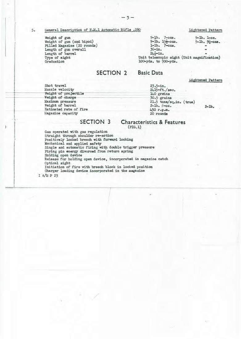
5. General Description of E.M.l Automatic Rifle .280. Lightened Pattern
Weight of" gun Weight of gun (and bipod) Filled Magazine (20 rounds) Length of gun overall Length of barrel Type of sight Graduation
Shot travel Muzzle velocity
SECTION 2
7-ozs. 14ozs. 7-ozs.
9-lb. 1-oz. 9-lb. ~za.
9-+b. 9-lb. 1-lb. 36-in. 24i-in.
Unit telescopic sight (Unit magnification) lOQ-yds. to 900-yds.
Basic Data Lightened Pattern
23.5-in.
-r----------~w~~~ecti~e·-------------
Weight of charge-- --~--------=Max:ilnum pressure
· 2415-ft./ sec. 140 grll':i.ns 30.5 grains 21.5 tons/sq.in. (true) 2-lb • . ~-oz. Weight of barrel
Estimated rate of fire 450 r.p.m. Magazine capacity 20 rounds
SECTION 3 Characteristics & Features (FIG,l).
Gas operated with gas regulation Straight through shoulder re-action Positive~ locked breech with forward locking Mechanical and applied safety Single and automatic firing with double trigeer pressure Firing pin energy divorced from-return spring Holding open d~vice Release for holding open device, incorporated in magazine catch Optical sight Initiation of fire with breech block in locked position Charger loading device incorporated in the magazine
I A/M-P 23


-5
SECTION 4 Handling
Magazine Filling
The magazine can be filled by .two separate and distinct methoda. A charger loading device is incoroorated in the magazine. ·
(a) Filling loose rounda by hand. (Fig.2) Hold the magazine in one hand, base of magazine . resting on thigh and front of magazine facing body. Place round on magazine platfonn and press round down and back with thwnb. Count the number of rounds. .
(b) Filling from charger. (Fig.3) The charger loading aevice is located in the rear of the magazine behind the magazine platform. To prepare magazine for filling, insert nose of bullet into circular recess on left of magazine and press upwards to full extent of slot. Hold magazine in left hand, pointing away :t'rom body; with thumb of left hand press the loading device forward and down until the two stops on the device engage on the rear lips of the magazine. Maintaining a firm forward presaln"e on the device with the thumb of the
1--t-------~leU-hand place chargeJ:Lint :the guide._ 'Place the thumb. on the top round just in front of the c~ar~; force the-rouna-into-the~az±ne-in one clean movement, pressing the top round down until it is engaged by the lips of the magazine. Flick the charger out of the. way with the right hand and load w:i.th additional chargers.
Loading and unloading (Lyinz position) (Fig .4-) (a) 1'o load. · Assume lying position. Hold weapon by pistol grip with the right hand, the gun
res,tin~ alon£: the right fore-arm, fore-fine;er alonG the trigger guard, the butt against the body. Full cocking handle to the rear in one strone crisp roovement. The v.urkins portions will remain to the rear, held up on the holdin~ open device. Tilt magazine opening to the left, controlling movement by the ri~ht hand and the pressure of the body against the butt.
P ick up magazine in left hand, place nose of ma:~az:i.ne into the magazine openine, ensuring that the f ront of the mazazine is held. up a.\,la inst the opening . Maintaining this position, sweep rear end of magazine into the openin;_:, allowing the v.orkinr; portions to came forward, feeding the t op round into the cham1)er and allowine ·the lll!l.gazine catch to en~aee and retain the magazine. Make safe by ~ushing the chanr;e lever (located on the left of the gun just behint.l the trigger) upwards to its hi~hest position .

J I
I .I I' I L
.-6-
(b) To unload. Tilt magazine to the left. Remove ·magazine by pressing magazine catch forward with. ·thumb of left hand, and with the same m:>vement re100ve the magazine. Press change lever downwards to "repetition" or "automatic" position. Cock gun. (1'his will eject the loaded round, and the 'WOrking portions will remain to the rear on the holding open device). Release holding open device by pressing magazine catch to the rear with the fore-finger ·of the left hand. Assume firing position and press the trigger. For additional safety it is advisable to re-cock the gun and carry .out the same sequence' qf operations. The gun is then clear. · Close ejection opening cover.
Adjusting the gas reguhtor (Fig.!))
The gas regulator has · three positions. "Normal'' 1 "more gaa" and "less gas". The gas regul&tor will alwa;vs be adjusted to Nonnal at the start of a shoot •
. Hold gun by fore-end, butt resting on ground. Press in for&-end retaining plunger with thumb (or fore-finger) and draw fore-end upwards •. Enough 100vement of the fore-end will be obtained to clear the gas regulator before the £ore-end is :Cetained by its c~tch.
Using the nose of a bullet depress the positioning stud of the regulator out of engagement with the positioning groove - and- turn- re ·· -- · - · pGsnion, allowing the stud to reassert
ua....po~U: J.onin~ · · ew_posl. J.on. e gas regu ator can be seen by the size o-f the gas port which is sbown airectly
on. top of the gas regulat·or. Note that by press'ing in the_ foi:e=end... retaining plunger, the fore-end can be sufficiently
~1;Mr.Awn_aa..ll.nw.-th:Ls-opal!'ation--to remove-the--fore-end completely from the barrel, the retaining plunger must be depressed, and turned.
Fitting the bipod-(Fig.6)
.Hold gun by fore-end, bUtt resting on ground; press the fore-end retaining plunger with thumb (or £:ore-finger) and turn until positioning slot in plunger . is- vertical. ilhen plunger is in this position it disengagoa from the fore-.end and the f'or&-end can be drawn upwards, clear of the barrel.
Place the neck of the bipod over the bipod attacbnent on the gun, · and swivel it into position. Replace fore-end, pressing in retaining plunger and~urnri until positioning slot is· horizontal.
.I A;1J P .23


_a_
Using fixed sight with inverted pointer and range graduations
{a) Zeroing {Fig.7) The pointer is intended to be zeroed to give a central M.P.I., at lOO-yards. The lens tube
thereaf'ter remains fixed in relation to the axis of the barrel, until such time as re-zeroing becomes necessary.
Vertical error (elevation) is canpensated. by fitting a thicker or thinner washer (or distance piece) on the elevation adjusting screw ( 1).
· La:l;eral error (l,ine) is compensated by fitting a thicker or thinner -washer (or distance piece) on the lateral adjusting screw {2).
{b) Afr g (Figs.B and 9) . im varies to allow .for the drop of' the bullet, under the influence of gravity, during
its time of flight over the range to the target. For ranges up to 100-yds. the tip of the pointer is brought down to the centre of the target. For succeeding ranges the pointer is raised above the centre of the target to a height which
represents the gravity drop _of th_e bullet over that distance. · - · e-on=:en-. RS.,Orh ~a ernate range graduations are marked {300
1 00, ·zoo ancl 900 yds.) These :z;raduation lines are brOken in the_centre (~.e. verticalJ,y beneath the
point~r) to allow the firer to see the target olearl;y when it is centralised. These lines are also used for levelling. __ (_c) Judging Distance
The vertical gaps between the graduation lines rray be used as a medium for quick judgement of distance. _ (Example - Assuming that the target is a f~gure of average height - say 5' 9" - then its distance may be roughl;y gauged as follows: with the feet standing on the 700-yds. line, if the head reaches the 30G-yds. line, the range is 30G=yds; if the- top of the head comes half-wey between the 300-yds. and 500-yds. lines, the range is 400-yds; if, the head is blocked out by the 50Q-yds. line the range is 50Q-yds. but if the head oan be seen the range is 60Q-yds.)
When the range to the target has been judged by thia or any other means, as a general rule the head of a target fig).lre less than 300:-yds. distant should be covered by the tip of the pointer, but for all subsequent ranges the appropriate pointer on the scale verticall;y beneath the pointer is brought to the centre of the target.
I A/J.I P 23
I
/

Z-1'/r .. nivuJ of ~/,~r;~ ----r-,. ..,.-7 ,..,..., Fig. 7

7-------9
/'
I
7-------9
~---s 7-------9
Fig. 8

----9
.BULL OF 4 FT TARGET AT 300 YARDS
BULL OF 6FT TARGET AT ~00 YARDS
(d) Aiming Sequence
(1~ (2 (3
(4)
(5) 1 .A,/l.!:P.23
Judge distance to target. Close left eye. Look through aperture at .target and select ~oint of aim. (N.B. a full field of view must be obtained). Place tip of pointer on selected point of aim, (at lOO~dsJ. At ranges over 100-yds. aim as explained above. Keep the sight upright.
Fig. 9
3 7-=:=:~-- 5 ----9

-12~
SECTION 5 Holding, Aiming & Firing "1 . AS A SELF-I.OADlNG RIFIE (Fig.lO)
. Hold the weapon by the pistol grip :with the right hand; the gun resting along the right fore-arm, fore-finger of right hand along the trigger guard. Assume the J.;ying position; use the left hand to assist movement. Grasp the weapon f:i.rml,y by the right hand, the magazine opening to .the left, and the weapon lying along the right fore-arm. The legs will be wide apart, body oblique to the line of fire. Load weapon as taught. Place the change lever to safe. Grasp the harid grip with the left hand, and look to the front. On a fire order being given, press change lever to the horizontal position and assume the firing position. '
Aiming - The right hand llllst be the master hand for every shot fired. The hold on the pistol grip should be fi:nn and controlled and a steady pressure applied to the rear 1 bearing the weapon into the shoulder and locking it there. Whenever the butt is brought into the shoulder the for&-finger must take the first pressure on the trigger. The left hand should fo:nn a support for the forWard end of the weapon; the grip should be firm without causing strain.
o p:LshouJ..d_be...made - to pull the rifle into the shoulder with the left hand. Owing to the straight thro_ugh reaction of. this weapon there is a tendency for the orthodox firer
when getting in the firing position, .to use only the heel of the butt in contact with the shoulder. This must be guarded against and a conscious effort made to bed as much of the butt into the shoulder as possible.
The whole position is final:cy locked by the wei£9;lt of .the head. pressing the chin downwards and to the right against the stock. 'The eye relief between sight and firer's eye should be in the region of 3-4" • The tripod for the rifle has now been fo:nned by the chest . and arms ana· the rifle has been locked on that tripod. Aim as· detailed in Section· 4. . ,.,.
Firing - On coming. into the . aim the firer must take the first pressure. Whilst concentrating on the target take an approximate aim.
Just before an accurate aim is taken breathing must be gently restrained. The instance that the eye registers the correct aim the second pressure will be taken and t he shot
fired. · · ' · The hold and aim must be maintained at least until the bullet has left the barrel. In fact it is advisable 'that the firer follow through unti:l the bullet has reached the target. Observe strike. Release pressure on the trigger cleanly and completely. The weapon has novr fed another round into t he chamber and the gun is · cocked ready to fire this round. If it is required to· fire another round the sequence i s as before. AUI - FIRE - OBSERVE -RE-AIM.
The slow rate of fire is 10 rounds per unnute.
I-S, '1I P ,23

ip
ke
is -
t

---------~~~~=~
F1g . 11 ( 1,
I
I ,lj
'(t
I

-(
-15-
2. AS A SUB J,i.ACH:rnE GUN (Fi,3.ll) Holding is of the first in1portance especial~ when firing in bursts. Correct holding can be
gained only by experience in firing ball ammunition. There are two positions for hold.in£: the Infantz:v Personal Weapon as a sub machine gun:-(a) Holding at the waist
The left foot is advanced with the knee slight~ bent, and the r i ght leg braced; the weight of the body being balanced on the left foot. The right hand is on the pistol erip with the forefinger on the trigger; the left hand on the forward erip supporting the weapon. The butt of the weapon is pressed tight~ against the side by the ris}lt arm. The left elbow is pulled back into the body and the complete weapon is thus clamped in its correct position so that when the body is turned to face an enemy the gun is instinctive~ aligned on to ·the target. Care must be "taken that the right fore-ann is kept in its correct position in line with the pistol gr-ip so as not to interfere with ejection.
(b) Holding in the shoulder
The position of the body and hands is the same as for holding at the waist; the right elbow - --- ----;· i-s-ra-ised 00-the..-right-s.houJ.dez:_.pushed-~ol!I'/Bl:d_:i.nto the butt with the left elbow almost under
the weapon.
Firing - Owing to_ the speed vdth which single rounds can be fired and also the fact that the · firer can correct ~n the strike much more easily, greater accuracy is obtained ~J firing single rounds,
and the need for econ~ of amounition is met, so that single round firing will be employed wherever possible. Bursts should be re~erved for extreme emereency and when used should be of two to three rounds on~. In the role of n1achine carbine the wea:pon can be carried in any convenient position but when expecting to meet the enemy it should be held at the waist. Althou~h the vreapon can be fired whilst on the move greater accuracy is obtained by halting momentarily to do so. For targets at about
. 25-yards the weapon may .be fired fran the waist by sense of direction. For ranges above this and if time pe:rmits aim will be taken using the sight.
3. AS A "LIGHT UACHniE GUN (Fig.l2)
The gun when · in the role of a light n.achine gun, will be fitted with a bipod. The vreapon vdll be placed gently on the .ground with the bipod upright and the butt of the gun resting on its right side bringing ·the magazine opening to the left.

-16-
Position for ' Loading -The body straight behind gun, legs together, left hand holds forward grip; right hand holds pistol grip; first finger along trigger guard when butt is on the ground; load as taught.
Holding - Holding· is most essential when the weapon is fired in this role as normally fire will be in bursts and although the weapon has little shock of recoil the automatic action of the gun when fired from the biped sets up vibration which unless controlled, throws the gun off its alignment.
This control can only be effected by correct holding which is essential for accurate shooting. Aiming position {Fig.l2) - Place left elbow on ground and hold forward grip with the left hand .
Raise the butt and place the butt into the shoulder by moving body forward into the gun.· Hold pistol grip in right hand exerting a downward and backwards pressure. Lock the gun into position. by pressing the head against the stock with the eye in correct aiming position.
Firing - The no:nnal rate of automatic 1'ire is 20 rounds per mnute fired in bursts of two to three rounds, In rapid fire. this is stepped up to 60 rounds per minute. Correct holding must be maintained throughout each burst. After each burst observe the strike of the shoot with a mm.mum. movement of the head and correct if necessary. The firer will alWBYs make allowance for side winds by applying the rules for aimi ·
unanging magazines~Ob a magazine being emptied-the-weapen-wi~ be swivelled r nging the magazine to the left. The magazine will be removed as· taught ·and the
inserted, which will release the holding open device and feed the first round into for firing. ' ---------
_SECTION 6 · ·Mechanism Backward.....ac.tion (Fig .13},--;:;...·----
on the bipod1 full magazine the chamber ready
S0111e of the gases following the bullet pass from the barrel, through the gas regulator into the gas cylinder. This forces the piston to the rear and compresses the return spring, until the piston 'comes to the end of ita stroke.
As the piston moves to the rear; a cam machined on the piston extension is brought out of \ . contact with the upper- sear lev , leaying the upper sear, unde;- the influence of its spring 1 ready to engage the upper bent of the hammer. At the same time the firing pin carrier is withdrawn from between the rollers, · allp1rl.ng them to move inwards and unlock the breech block. Also during this primary movement a stud on the underside of the piston extension engages the cocking plate in the barrel block, and cocks the hallmer which is retained by the upper · sear. After the breech block is unlocked, it is carried. to the rear, under the influence of the piston, carrying with it the fired. cartridge case on the extractor, until the ' ejector clears it through the ejection opening in the
' body. . i.A,IM.P.23

1
'
l'.
r
Fig. 13
I. Gun fired, gases follow bullet, passing t~rough gas regulator into gas cylinder.
2. Breech block locked by rollers . 3. Firing pin carrier moves to rear. Breech block unlocked .
~Piston
5. Hammer retained by upper sear.

I. Breech block moves forward, rollers opposite recesses.
BREECH
3. Cam on piston lifts upper sear, releases hammer on to the
lower sear; ready for firing.
:/
Fig. 14
2. Firing pin carrier moves forward, rollers lock breech block.
BREECH
4. Trigger pressure operates bottom sear, releases hammer
which in turn operates fir ing pin.

19
Forward action t Fig.l4)
The piston, having reached the end of its stroke, is forced forward by' the return spring, carrying with it the breech block. · The face of the breech block meets the base of the top round in the magazine and forces it forward into the chamber, the extractor closing over the rim.
As the brftech block is arrested at the chamber, the locking rollers are opposite their recesses in the\ barrel block. Further movement of the piston cams these rollers into their locked position, and they are retained there by the firing pin carrier I which iS tapered to inflUence the rollers. Short~ before the piston reaches its fu~ forward position the cam on its extension lifts the upper sear and releases the hammer onto the lower sear.
Applied safety is provided by the change lever in the "safe" position (Fig.l5). When the change lever is in this position, the trigger is locked, and two safety levers in the trigger mechanism positively lock the hammer and the piston.
L!echanical safety is provided by positive locking of the breech block during firing. No protrusion of the firing pin is possible until after the breech block is in the locked position as the position
--..:----nf''-+he--Iock::tng-rcf.l±ers-regu-:mte--t~:ltiOIJO_f'-tlie_firing_pin_Q_arrier within the breech block,
CHANGE LEVER DETENT & SPRING
FETY LEVERS
CHANGE LEVER
LOWER TRIGGER
TRIGGER SPRING ROD
CHANGE LEVER H Fig IS.
SAFETY CATCH APPLIED
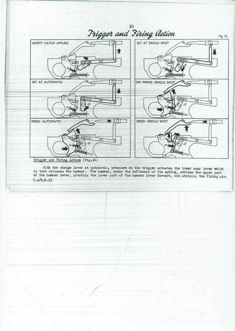
With the change lever at automatic, pressure on the trigger actuates t~e lower sear lever which in turn releases the hanmer. The hammer, under the inf'luepce of its spring, strikes the upper part . of the haminer lever, pivoting the lower part of the hammer lever forward, and striking the firing pin; I.A/M.P.23
I /

6 -
-
-
Ln;
a s long as the trigger is pressed, the gun will continue to fire but if the tri.P;ger is released the lower bent of the hammer will be free to engage on the lower sear, durlng this last forward action, a round will be fed into the breech, and the action will lock, but the gun will not fire.
With the change lever at "single shot" the trigger must be released and pressed each t:ilne a shot is to be fired, as the trigger pawl is tripped out of engagement with the upper part .of the trigger, which can then no longer actuate the lower sear lever. ·
Note that pressure on the trigger only actuates the lower sear. The function of the upper sear is to retain the hammer until the action is locked.
With the change lever at "safe" the trigger is positively locked, and two safety levers positive~ lock the hammer and the piston.
Holding Open Device A ho.iding open device (Fig.l) is incorpOrated (with the magazine catch) in the body of the gun,
behind the magazine opening. This · devico holds the working portions to the rear when· an emp't\1 magazine, or no magazine is in the gun. On a full magazine being placed in the gun, ·the holding . open device is pivoted out of engagement with the breech block, which is then !lriven forward, under .... e action of the I e tur u spring, feredindh'e-t1 · ound-itrthe~azine, int.o the chamber, and locking the action.
The gun is then ready to fire. If it is required to clear the gun, the magazine is removed and the cocking handle pulled to the rear. This will ejeot the unfired round and th~ recoiling portions will remain to the rear, held up on ~e holding open device. To re-lease the hqlding open device frcm the breech block, press the magazine catch to· the rear. This will' allow~e working pcirtions to go forward, under the action of the return spring, and lock "·the action. Press the trigger to · release the firing. pin. The gun is now clear.
SECTIO_N 7 ' Immediate Action
If the 'gun is properly cared for, stoppages other than an empty magazine will rarely occur. Immediate ·action is the action perfonned by the firer to ·remed;y a· stoppage. It inust be carried
out quick~, and with practice, should become ' i~stinctive. ~ate action is not complete until the gun has been re-aimed and fired.
If the gun fails to fire, or stops firing:-Immediate action. ReiOOve magazine; pull back cocking handle; release holding open devico;
pull back cocking hsndle; replace magazine; a:im g_un and fll-e. ~: If cocking handle stops to the :rear,. it indicates, NOT a stoppage, but an empty magazine.
Ir.mediate action. Remove empty magazine; replace full magazine; a:im gun and fire;
I A/MP 23

22

(f) . Fig. 18

-24-
To assemble Replace gas regulator; stand body of gun on butt, and slide the barrel group, in its
positioning grooves, back into the body, until the gas block is about to enter the body; then press magazine catch to the rear; this withdraws the ejector from the pathway of the barrel group; maintaining the ejector in this position force barrel group home; care must always be taken · that the ejector is kept clear of the pathway of the barrel group during this last stage of assenibl3", otherwise the barrel group cannot be forced home, and damage to the ejector will ensue.
Replace trigger group, ensuring the tv10 safety levers are properl3" inserted into their recesses in the body, and secure with the two :fixing pins. Replace. cocking handle in its slot, cock gun, and action will remain to the rear, held up on' the holding open device.
Feed return spring through butt, into the gun and vmen resistance is felt, thread as much of the spring as is possible on to the return spring rod, feed nose <;>f rod into the recess in the butt, and push rod into the gun. 1laintaining pressure on rod, release the holding open device, the working portions will go forward, and the head of the return spring rod may then be inserted into its seating. Vflhen rod is ful~ home, turn the head until the positioning slot is horizontal across the t t=The- roa is-now-: oc - in pos:i,tion •
• B. It is most importa:nt-'tl:rh:ol4 the liOrld ng pol'tions-to-the rear as taught while inserting - e s ring.
Replace fore-end, pressing in retaining plunger, aOO. turning it,. until positioning. slot is horizontal.
Cock-gun, release holding open device, press trigger to clear gun and check functioning. Close ejection ooening cover.
SECTION 9 Advanced Stripping ' (FIGs.l9 AND 20) . . -
To strip barrel group - comprisin,1 piston aqd e::tension, · breech block and har,llner unit. First ensure that action is cocked (to release the locking rollers frau their recesses in the breech) ; to do this , replace cocking handle in recess of piston, place the tip of the cocking handle on an ammunition box, etc , muzzle pointing avr.."Y fran the u~er, and press do"l"m on the cocking handle, which is withdrawn. Proceed as follows:-
(a) ~'.'ithdraw piston and breech block slishtly from the barrel block, withdraw hammer unit retainin3 pin, and vlithdt'avr haxmter unit forward frrn. block, ensurine that the top and bottom sear levers are NOT pressed toc;ethe!' durin(S the process.
I ~r .P 23
./

2'5
. (a)
(c)
~;51 ~t-=)::=;1 ~ri®
(d)
(b)
(jJ
(b) Withdraw piston and breech block clear of barrel block - turn barrel block upside down, and shake out the cocking plate. (c) To remove breech block fran piston e.xtension, press retaining spring rings of breech block extension inwards, into the positioning slots on the extension, and slide extension do\vowards. out of engagement with the breech block. Slide pi'ltoq t.o the ~ear,. disengaging the hammer lever from its recess in tne firing pin carrier. _(d) .To remove firing pin- insert nose of bullet into rear of the firing pin carrier, and press forward to relieve pressure of spring; press out the retaining pin; release pressure on rear of firing pin ~nd withdraw firing pin and spring from the rear.
I AIM P 23

26
(e) (f) I
(e) To strip breech block - inserj; naii of finger under the spring retaining rollers (situated on top ' or e reech lock lift slightly, and the locking rollers will shal<e out. Insert nose of bullet under nose of horse-1illbe spring, press up; and slip spring from front portion of the breech block; lift out the extractor. · · {f) To strip hammer unit - hold hammer unit with fingers and thumb, so that pressure can be exerted on the upper and lower sear levers. 'Place nose 'of hammer on ground, and press the two sear levers together. This will release the hamner and spring from their housing.
To re-assemble reverse the above .operations, noting the following points:-
( a) The hammer; Ensure bent nearest nose of the hammer is posi ti:Oned to engage with the upper sear , (b) The firing pin; Press firing pin forward against action of spring, before trying to insert the retaining pin. (c) The firing pin into the breech block; Ensure the hammer leyer is held almost parallel with the breech block, until firing pin carrier is inserted, then ensure the hal:m!ler lever fits into its recess in the firing' -pin carrier. slide on bret'lcih--oTock extension ana. secure with spring. (d) The breech block in the locked position in the breech; Withdraw firing pin carrier to rear of the breech block, collapsing the locking rollers. Ease breech block forward into breech, and when fully home press piston extension forward, influencing the rollers into their locking recesses, and disengaging the upper s .ear from its bent in the hammer. Press lower sear lever upwards, firing the hammer; and positively locking the action. I A/MP 23

-27~
SECTION 10 Clean_ing & Maintenance
Stores creariing rod (at present P.H •• 22-inch rod); Pull through; Gauge; Cylinder cleaning rod;
Cylinder cleaning wire brush; Qylinder cleaning mop;- Oil container; Flannelette.
Daily cleaning Clean barrel, using the cleaning rod. A dry piece of flannelette, 4--in. py l~in. will
be put half way through the eye at the end ~f the cleaning rod. The action will b~ cocked, and the rod will be inserted from the muzzle end.
When the barrel has been cleaned with dry flannelette, a slightzy · smaller piece of flannelette, well oiled, will be similarzy used to oil the barrel.
· v Before firing: Strip completezy (-rlth the exception of the bolt). Clean and leave dry the gas affected parts i.e. barrel and breech; gas cylinder 1 using
1 the cleaning rod and mop; the gas regulator; head of the piston;_face of the bolt. lean remainder of gun and slight~ a-i-1 the-'I!Crldng-parts-. -
When assembling, se gas regUlatOr at nor.mai. C ean magazines, pa;ying particular attention to the _~azine ~latform.
After ru-1ns Strip completezy, Clean barrel as for rifle, using boiling water if available, anu gauze
?/hen necessary. Clean gas cylinder with cylinder cleaning rod, wire brush anq. mop. Clean with oil;y rag
remaining parts; then dry 1 clean and slightl;y oil. In the absence of a cleaning rod, a pull through 1I11J3 be used, the weight inserted through
the breech and dropped through the barrel. · . · The gas cylinder (which is detachable) ms.y be cleaned in a similar we:y, after removal of
the gas regulator._
Note
A feature of this weapon is that under field conditions I the gas regulator and gas cylinder can be cleaned with a minimum of stripping.
Remov~ fore-end and gas regulator as taught. The gas cylinder can then be cleaned, with_ the cylinder cleaning rod. wire brush and IDDP, without any further stripping. ·
I -.A/M .P 23

-- 1tseof~ Fig. 2 1
@

-2.9~
.SECTION 11 Use of Sling (FIG.21)
The sling may be used as a valuable .aid to steadiness when firing single round or automatic fire.
(a) Hold the rifle in the right hand, by the pistol grip; pass the left pand through the loop in the sling, from left to right.
(b) Then pass the left hand round the front part of the sling, in a clockwise direction, and grasp the rifle at the forward grip.
(c) Draw the rifle slightzy back and with the right hand hitch the loop of the sling well up the left upper arm and assume the aiming position.
To adjust
1---:--------r-t-±-a-±mporta:nt-th:a:t-the loop of'-the-s-l:!:ng-± usted to the correct length for the firer. If it is found to be too -loose,--ti&h-te~.lid-ing-~e-me.tal-clip on the lOop towards the forward swivel on the rifle, and pick up slack on rear D piece. It will be found that when the sling is correctlY adjusted for the firer, as an aid to steadiness, it will also be in adjustment for grenade firing.
SECTION 12 Grenade Firing ' (FIG3.22 .AND 23 )
In order to f:ire a grenade fran the rif"le,- a proJector will be attached to the rifle 1
which. is then loaded with a-grenade cartridge, and the grenade placed on the projector. On the grenade cartridge being fired, the grenade is discharged.
Description of Projector and Sights
The projector consists of a . ribb~ cylindrical steel tube, with a grenade retaining clip -fa stened between tv.o of the rear ribs. On one end there is a bayonet type socket which is fitted with a spring catch, to retain the projector on the muzzle of the rif"le. ~: The grenade sight (fig.22) is superimposed on the projector, and consists of an arm slotted · and shaped to give three ranges - 50-yards, 75-yards and 100-yards. The complete s i ght can be r aised and lo1vered in t he pro ject or,and is held in position by a positioning stud.
I .1\11i P 23

Fig. 22
100 YARDS 75 YARDS SO YARDS
GRENADE ..... A p A
PROJECTOR
/ /

To fit projector to gun (Fig.22)
Hold weapon with one hand, and place projector on the rifle.· Turn projector until the · cut away portion in the projector coincides with the retaining lugs on the barrel. Press projector down firmly until it reaches its full extent or· engagement (compressing the spring retaining catch) then turn projector until the spring catch re-asserts itself and snaps into position locking the projector on to the rifle.
To remove, rl4se catch with fore-finger and thumb to full extent, swivel projector to disengage it from retaining lugs, and withdraw.
To fire a grenade (a; Remove magazine and clear gun. (b) Attach projector to weapon as taught, and raise sfghts. (c) Cock gun, allowing the recoiling portion to be held up on the holding open device. (d} Load grenade cartridge direct into the-breech by hand. (This is best done by tilting the magazine opening to the left and inserting the grenade cartridge direct into the breech, through the magazine opening.) e · · Release holding open device and· put change lever to _safe. f a grena e on o pro eo or,._ g._ z-.t:IDrrru:ng gtenaa:e tail.
(g · .Assume correct firing-pos±t±on-by-hoiding-weapon-;r.t-th-the-right hand as pistol grip. Place left · ann under the rifle and above the sling. (F'ig .22) .
Pass the left hand round the front part of the sling in a clockwise direction and grasp the rifle at the forwarci grip. Draw the rifle slightl,y b_ack and with the right hand place the sling across t he upper part of the chest (Fig.22) and finally lock the rifle into position by placing butt under right ann pit (Fi g.22). If the correct position has been assuned the weapon should be rigin~ fixed, with the sling l,ying taut across the upper chest, and th~ butt,held in position by the tension on the sling, and clamped into position, under the right arm pit by the right upper arm.
A f inn grip should be maintained with the left hand. -To _aim
Lower head until eye looks along the approximate line of eight of the rifle (Fig.22). Raise or lo'.ver the muzzle of the rifle until the silhouette of the grenade corresponds With the
appropriate r ange circle on t he s ight. The rifle is then at the correct elevation f or t hat particular range. .
For r anges over one hundred yards, depending on the cover and the f iring position, the grenade may be fired as described above, estinlating i ncreased elevation to give t he desired r ange, or t he hee l of the butt may be placed on the ground, the estimated t a ngent elevati on appl ied to t he gun (in relRtion to the ground) , and the trigcer pressed with the strai bht fore-finger ( Fi~.23 ).
I Ajl.I .:i.- 23

-5.2-
Points to note when firing a grenade fra-.1 this position:(a) Heel of the butt on the ground. (b) Left hand forward of the hand grip (to avoid interference with the cocking handle). (c) Ric;ht hand clenched, with straight fore-finger. . Fore-finger resting on trigger. Trigger
pressed qy complete movement of hand. (d) Heel of butt placed outside position of right knee. An alternative method of holding has been evolved with the butt in the shoulder and the
shortened sling passing from the butt, across the chest, under the arm pit and over the upper arm to the front swivel. This position would ap~ear to give a better firing position and facilitate sighting, but has the disadvantage that the considerable shock of recoil is taken most~ on the shoulder.
Il0~13 l Jse...o the Bayonet (F~G.24)
The No.7 bayonet (modified) is used with this automatic rifle. To attach 'the bayonet to the rifle, rotate the- socket-t'rom the-normal "knife"-posi tion until the spring catch position is in line with the ring of the cross piece. The socket and cross piece are then placed over the barrel and turned until the cut away portion in the socket coincides Vlith the retaining lugs on the barrel. Press down firm~ and turn until the spring catch on the socket reasserts itself and snaps into position locking the bayonet on to the rifle.
To remove, raise catch with fore-finger and thumb to full extent, swivel bayonet to disengage it from retaining lugs and withdraw.
In bayonet fighting with the automatic rifle, handling will be along normal orthodox lines, and the "on guard" position will be assumed by taking a full pace forward with the left foot, and at the same time bringing the rifle up to a natural fighting position. It is suggested that,during close quarter fighting, while a full magazine is on the gun, the "Bullet and bayonet" position should be adopted. This enables the soldier to use the bullet, and, to a limited extent, the bayonet,tqgether •.
When the magazine is empty or when it is NOT desirous to fire the rifle (say • during a silent night attack) the "bayonet" position should be adopted, This position would appear to give maximum length during the "point" and a greater choice of handling position, in offence and defence,without disturbing the grip of the hands.
I -A/MP 23

&u~tade 'fiUitj Fig . 23
er.
Fig. 24
- ----

-34.-
Points to · note "Bullet - Bayonet" Position
(a) Left hand on hand grip, right hand on pistol grip, fore-finger on trigger, but butt of the weapon pressed fi.rml,y against the side, by the right arm. "Point" to be made by straightening left arm and thrusting forward rifle with right arm.
"Bayonet" Position (b) Left hand should have a. finn grip. on the fore-end, the right hand just clear of the butt, holding round the stock.
CONFIDENTIAL- DISCREET
I A/M P 23


I J
.:5ide views of we e.pon.
Plan. Fore-end moved forward for access to gas re~lator.
~$3~ .......... _. ................ ~~~~~~~~~~~~~~~~~~"'~\U~'III~"'~'"~W~"'~t"~"%~"M~»'~"'~M•~"'~"'~"'~"''m"'~"'~"'•"''M*MidiMiiMMMMJZ=-s•as•naMe:Mmmmmmmmmmmmmmmnnmmmmmmmnnmllmmmii~-. .. .-.... JI

P. N. _ 280 .FJ.UTO. CRRBiNE
.Sfiorf 11 ode/. .


/

f. . 280 fl UTO. CJJ.RBiNE
Long !1.odel,