Embed Size (px)
Citation preview
e-link IP for FE ASICs
VFAT3/GdSP ASIC design meeting
19/07/2011
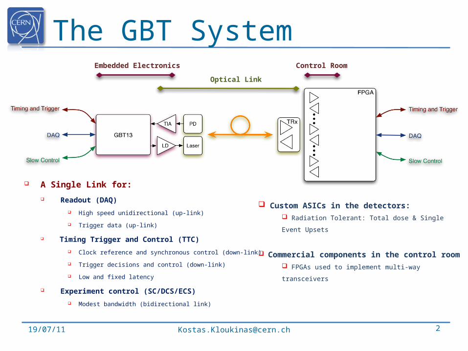
The GBT System
A Single Link for:
Readout (DAQ)
High speed unidirectional (up-link)
Trigger data (up-link)
Timing Trigger and Control (TTC)
Clock reference and synchronous control (down-link)
Trigger decisions and control (down-link)
Low and fixed latency
Experiment control (SC/DCS/ECS)
Modest bandwidth (bidirectional link)
19/07/11 [email protected] 2
Embedded Electronics Control Room
Optical Link
Custom ASICs in the detectors: Radiation Tolerant: Total dose & Single Event Upsets
Commercial components in the control room FPGAs used to implement multi-way transceivers
FramerSerDesFramerSerDes
GBT link
e-porte-port
e-porte-port
e-porte-port
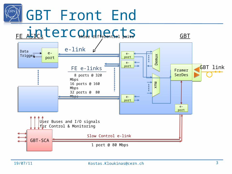
FE e-links
Slow Control e-link
FE ASICs
e-linke-porte-port
DataTrigger
8 ports @ 320 Mbps16 ports @ 160 Mbps32 ports @ 80 Mbps
GBT
De
mu
xD
em
ux
mu
xm
ux
GBT Front End interconnects
19/07/11 [email protected] 3
User Buses and I/O signals for Control & Monitoring
three differential pairs
GBT-SCAGBT-SCA
e-porte-port
1 port @ 80 Mbps
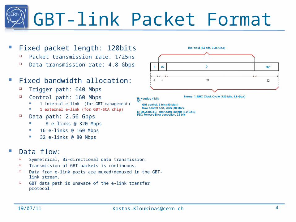
GBT-link Packet Format Fixed packet length: 120bits
Packet transmission rate: 1/25ns Data transmission rate: 4.8 Gbps
Fixed bandwidth allocation: Trigger path: 640 Mbps Control path: 160 Mbps
1 internal e-link (for GBT management) 1 external e-link (for GBT-SCA chip)
Data path: 2.56 Gbps 8 e-links @ 320 Mbps 16 e-links @ 160 Mbps 32 e-links @ 80 Mbps
Data flow: Symmetrical, Bi-directional data transmission. Transmission of GBT-packets is continuous. Data from e-link ports are muxed/demuxed in the GBT-link stream. GBT data path is unaware of the e-link transfer protocol.
19/07/11 [email protected] 4
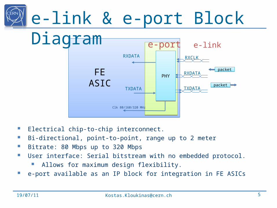
e-link & e-port Block Diagram
19/07/11 [email protected] 5
Electrical chip-to-chip interconnect. Bi-directional, point-to-point, range up to 2 meter Bitrate: 80 Mbps up to 320 Mbps User interface: Serial bitstream with no embedded protocol.
Allows for maximum design flexibility. e-port available as an IP block for integration in FE ASICs
RXDATA
TXDATA
e-port
packetpacket
packetpacket
e-link
Clk 80/160/320 MHz
PHYPHY
RXCLK
TXDATA
RXDATA
FEASIC
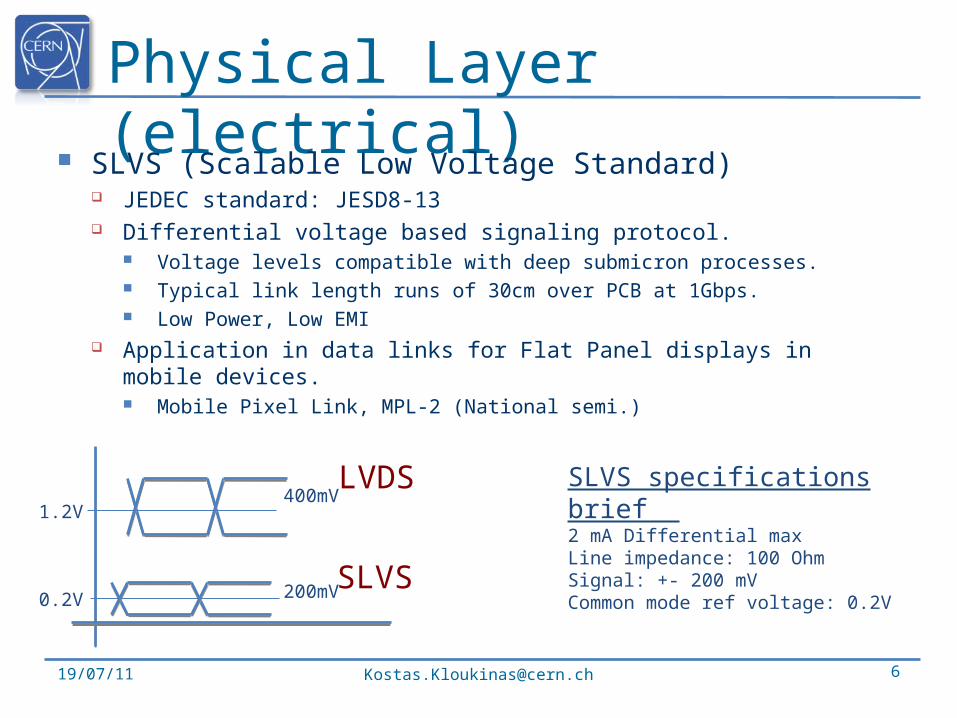
Physical Layer (electrical)
SLVS (Scalable Low Voltage Standard) JEDEC standard: JESD8-13 Differential voltage based signaling protocol.
Voltage levels compatible with deep submicron processes. Typical link length runs of 30cm over PCB at 1Gbps. Low Power, Low EMI
Application in data links for Flat Panel displays in mobile devices. Mobile Pixel Link, MPL-2 (National semi.)
19/07/11 [email protected] 6
SLVS specifications brief 2 mA Differential maxLine impedance: 100 OhmSignal: +- 200 mVCommon mode ref voltage: 0.2V
0.2V
1.2V400mV
200mV
LVDS
SLVS
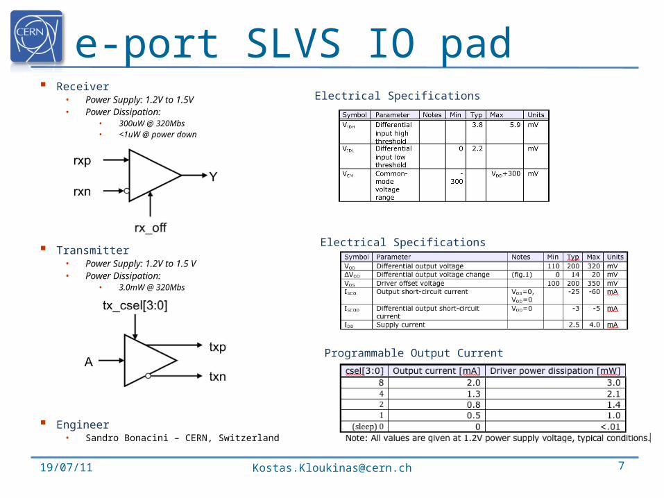
e-port SLVS IO pad
19/07/11 [email protected] 7
Receiver• Power Supply: 1.2V to 1.5V• Power Dissipation:
• 300uW @ 320Mbs• <1uW @ power down
Transmitter• Power Supply: 1.2V to 1.5 V• Power Dissipation:
• 3.0mW @ 320Mbs• <10uW @ power down
Engineer• Sandro Bonacini – CERN, Switzerland
Electrical Specifications
Electrical Specifications
Programmable Output Current
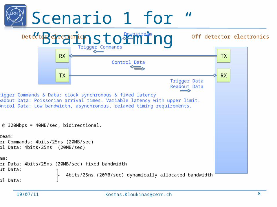
Scenario 1 for “Brainstorming”
19/07/11 [email protected] 8
RXRX
TXTX
TXTX
RXRX
Trigger Commands
Trigger DataReadout Data
Control Data
Off detector electronicsDetector electronics
Trigger Commands & Data: clock synchronous & fixed latencyReadout Data: Poissonian arrival times. Variable latency with upper limit.Control Data: Low bandwidth, asynchronous, relaxed timing requirements.
Downstream
e-link @ 320Mbps = 40MB/sec, bidirectional.
Downstream:•Trigger Commands: 4bits/25ns (20MB/sec)•Control Data: 4bits/25ns (20MB/sec)
Upstream:•Trigger Data: 4bits/25ns (20MB/sec) fixed bandwidth•Readout Data: 4bits/25ns (20MB/sec) dynamically allocated bandwidth•Control Data:
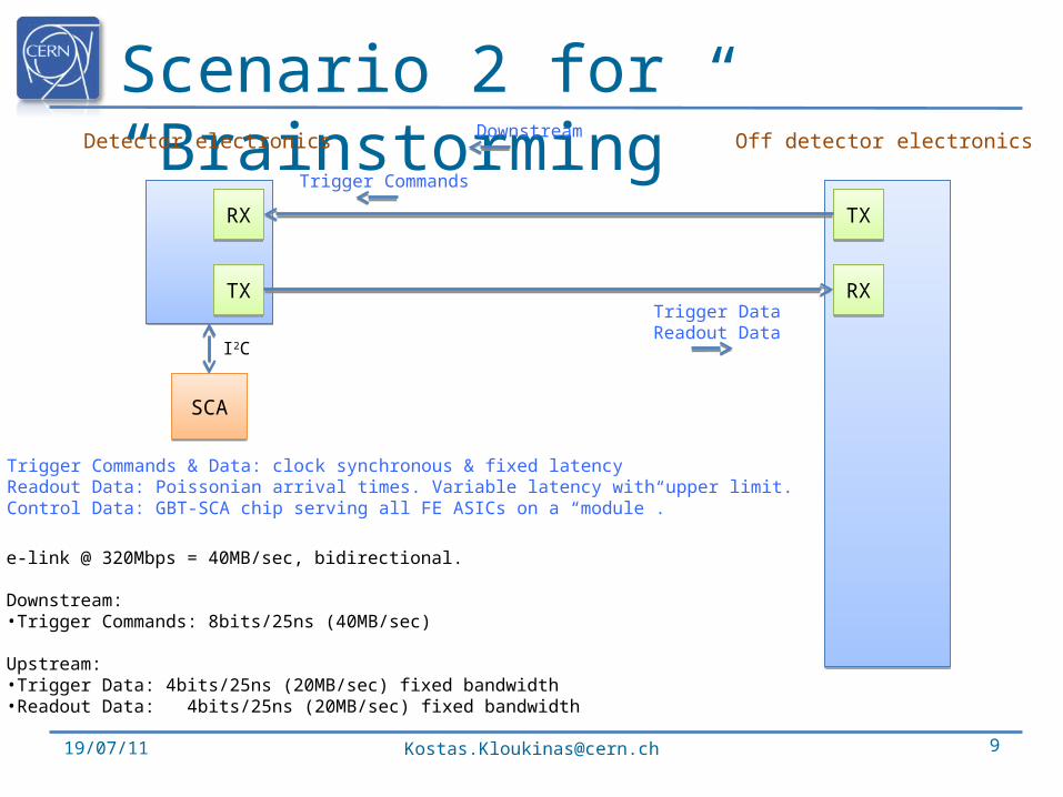
Scenario 2 for “Brainstorming”
19/07/11 [email protected] 9
RXRX
TXTX
TXTX
RXRX
Trigger Commands
Trigger DataReadout Data
Off detector electronicsDetector electronics
Trigger Commands & Data: clock synchronous & fixed latencyReadout Data: Poissonian arrival times. Variable latency with upper limit.Control Data: GBT-SCA chip serving all FE ASICs on a “module”.
e-link @ 320Mbps = 40MB/sec, bidirectional.
Downstream:•Trigger Commands: 8bits/25ns (40MB/sec)
Upstream:•Trigger Data: 4bits/25ns (20MB/sec) fixed bandwidth•Readout Data: 4bits/25ns (20MB/sec) fixed bandwidth
SCASCA
I2C
Downstream
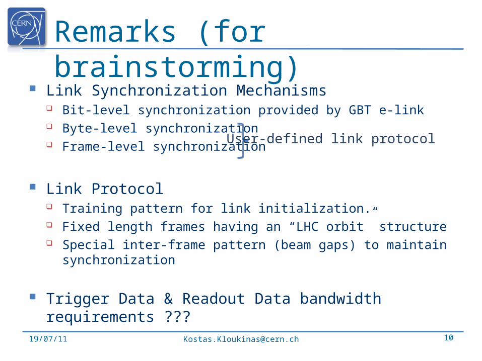
Remarks (for brainstorming)
Link Synchronization Mechanisms Bit-level synchronization provided by GBT e-link Byte-level synchronization Frame-level synchronization
Link Protocol Training pattern for link initialization. Fixed length frames having an “LHC orbit” structure Special inter-frame pattern (beam gaps) to maintain
synchronization
Trigger Data & Readout Data bandwidth requirements ???
19/07/11 [email protected] 10
User-defined link protocol

19/07/11 [email protected] 11
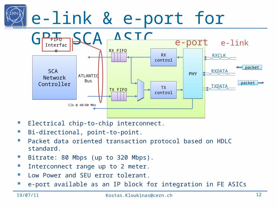
e-link & e-port for GBT-SCA ASIC
19/07/11 [email protected] 12
Electrical chip-to-chip interconnect. Bi-directional, point-to-point. Packet data oriented transaction protocol based on HDLC standard. Bitrate: 80 Mbps (up to 320 Mbps). Interconnect range up to 2 meter. Low Power and SEU error tolerant. e-port available as an IP block for integration in FE ASICs
RXcontrol
RXcontrol
TXcontrol
TXcontrol
TX FIFO
RX FIFO
RXDATA
TXDATA
ATLANTICBus
FIFOInterface
e-port
packetpacket
packetpacket
e-link
SCA Network
Controller
SCA Network
Controller
Clk @ 40/80 MHz
PHYPHY
RXCLK
![Design flow for readout ASICs in High-energy Physics ... · Mixed-signal ASIC design flow is generally described in the manuscripts [1, 2]. The design of the ASICs for high-energy](https://img.pdfslide.us/doc/110x75/5f8305ceb607397056135b18/design-flow-for-readout-asics-in-high-energy-physics-mixed-signal-asic-design.jpg)