Embed Size (px)
Citation preview
1
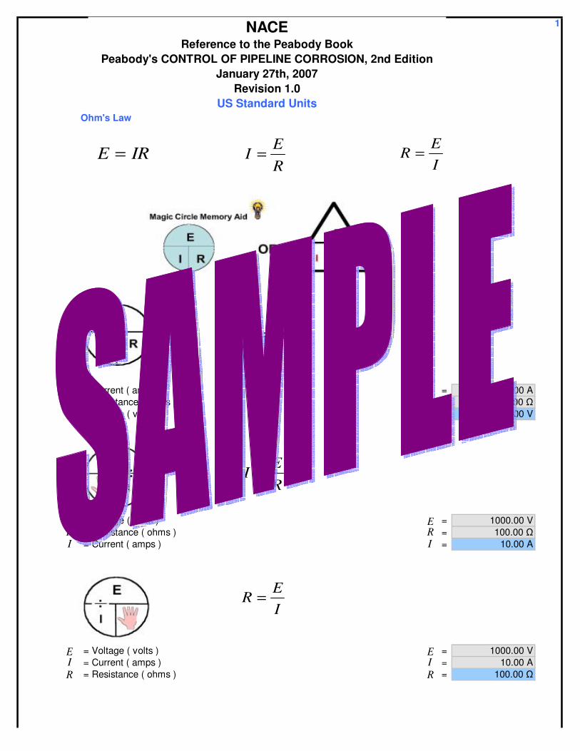
Ohm's Law
= Current ( amps ) = 10.00 A = Resistance ( ohms ) = 100.00 = Voltage ( volts ) = 1000.00 V
= Voltage ( volts ) = 1000.00 V = Resistance ( ohms ) = 100.00 = Current ( amps ) = 10.00 A
= Voltage ( volts ) = 1000.00 V = Current ( amps ) = 10.00 A = Resistance ( ohms ) = 100.00
NACEReference to the Peabody Book
Peabody's CONTROL OF PIPELINE CORROSION, 2nd EditionJanuary 27th, 2007
Revision 1.0US Standard Units
IRE =RE
I =IE
R =
IRE =
E
IR
E
IR
RE
I =
E ER RI I
IE
R =
E EI IR R
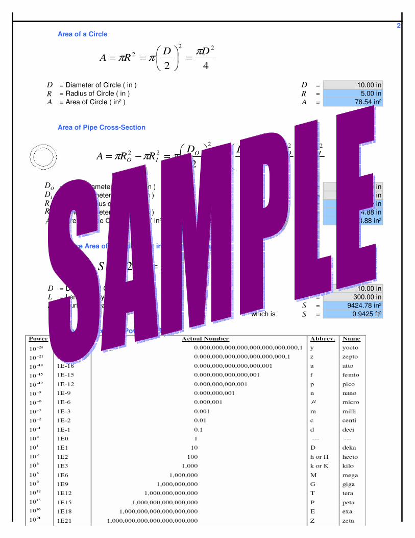
2Area of a Circle
= Diameter of Circle ( in ) = 10.00 in = Radius of Circle ( in ) = 5.00 in = Area of Circle ( in² ) = 78.54 in²
Area of Pipe Cross-Section
= Outer Diameter of Circle ( in ) = 10.00 in = Inner Diameter of Circle ( in ) = 9.75 in = Outer Radius of Circle ( in ) = 5.00 in = Inner Diameter of Circle ( in ) = 4.88 in = Area of Pipe Cross-Section ( in² ) = 3.88 in²
Surface Area of Cylinder ( not including end caps )
= Diameter of Cylinder ( in ) = 10.00 in = Length of Cylinder ( in ) = 300.00 in = Surface Area of Cylinder ( in² ) = 9424.78 in²
which is = 0.9425 ft²
Various Prefixes for Powers of Ten
42
222 DD
RAπππ =
==
AR
AR
D D
4422
222222 IOIOIO
DDDDRRA
ππππππ −=
−
=−=
ODIDORIR
A
ODIDORIR
A
DLRLS ππ == 2
SLD
SLD
S
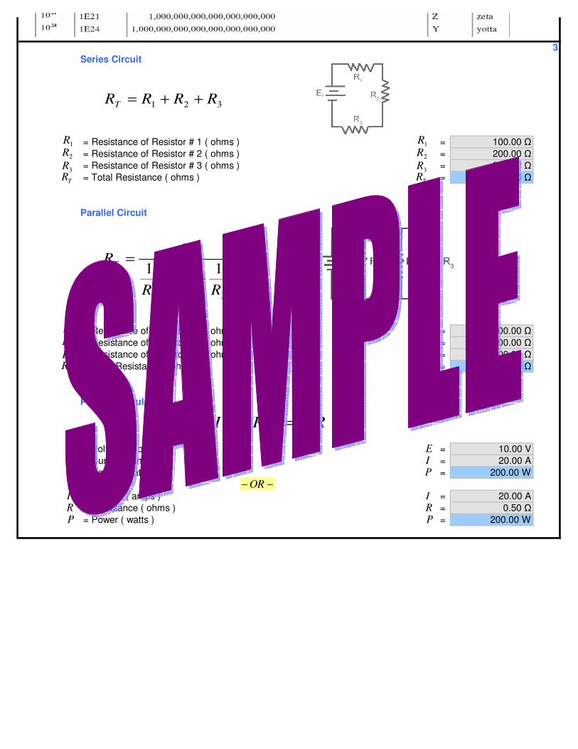
3Series Circuit
= Resistance of Resistor # 1 ( ohms ) = 100.00 = Resistance of Resistor # 2 ( ohms ) = 200.00 = Resistance of Resistor # 3 ( ohms ) = 300.00 = Total Resistance ( ohms ) = 600.00
Parallel Circuit
= Resistance of Resistor # 1 ( ohms ) = 100.00 = Resistance of Resistor # 2 ( ohms ) = 200.00 = Resistance of Resistor # 3 ( ohms ) = 300.00 = Total Resistance ( ohms ) = 54.55
Power Formula
= Voltage ( volts ) = 10.00 V = Current ( amps ) = 20.00 A = Power ( watts ) = 200.00 W
= Current ( amps ) = 20.00 A = Resistance ( ohms ) = 0.50 = Power ( watts ) = 200.00 W
TR
1R2R3R
TR
1R2R3R
RIIIREIP 2)( ===EI
EI
IRP
IRP
P P−− OR
TR
1R2R3R
TR
1R2R3R
321
1111
RRR
RT
++=
321 RRRRT ++=
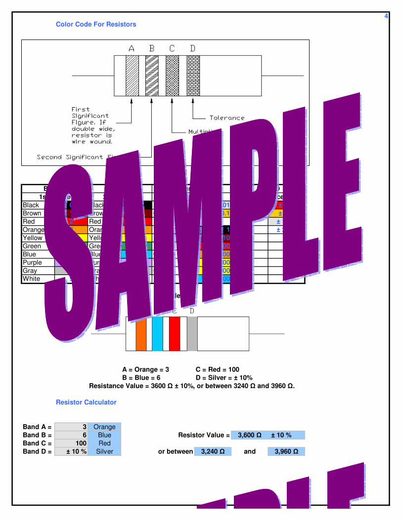
4Color Code For Resistors
Values
Black 0 Black 0 Silver 0.01 Red ± 2 %Brown 1 Brown 1 Gold 0.1 Gold ± 5 %Red 2 Red 2 Silver ± 10 %Orange 3 Orange 3 Black 1 None ± 20 %Yellow 4 Yellow 4 Brown 10Green 5 Green 5 Red 100Blue 6 Blue 6 Orange 1,000Purple 7 Purple 7 Yellow 10,000Gray 8 Gray 8 Green 100,000White 9 White 9 Blue 1,000,000
Example
A = Orange = 3 C = Red = 100B = Blue = 6 D = Silver = ± 10%
Resistance Value = 3600 ± 10%, or between 3240 and 3960 .
Resistor Calculator
Band A = 3 OrangeBand B = 6 Blue Resistor Value = 3,600 ± 10 %Band C = 100 RedBand D = ± 10 % Silver or between 3,240 and 3,960
Band D1st Figure 2nd Figure Multiplier Tolerance
Band A Band B Band C
±±
±±
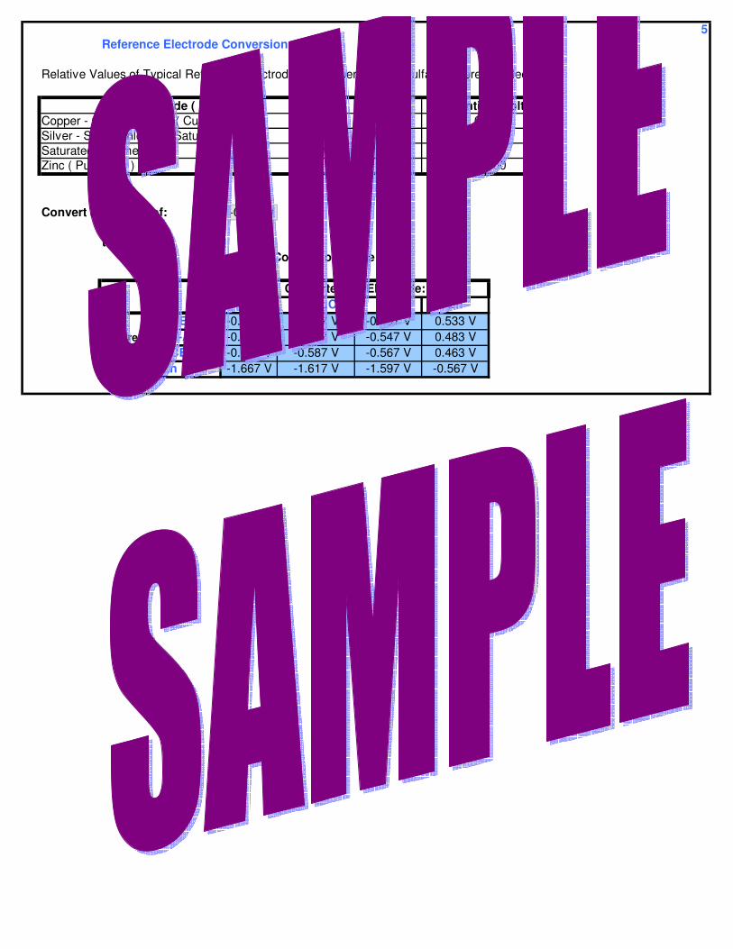
5Reference Electrode Conversions
Relative Values of Typical Reference Electrodes to Copper-Copper Sulfate Reference Electrode
NameCSE
Ag-AgClSCEZn
Convert a Reading of: -0.567 V
to:
CSE Ag-AgCl SCE ZnCSE -0.567 V -0.517 V -0.497 V 0.533 VAg-AgCl -0.617 V -0.567 V -0.547 V 0.483 VSCE -0.637 V -0.587 V -0.567 V 0.463 VZn -1.667 V -1.617 V -1.597 V -0.567 V
Reference Electrode
Zinc ( Pure Zinc ) -1.100
Electrode Conversion Table
Converted To Electrode:
Silver - Silver Chloride ( Saturated ) -0.050Saturated Calomel -0.070
Electrode ( Half - Cell ) Potential ( Volts )Copper - Copper Sulfate ( Cu-Cu SO4 ) 0.000
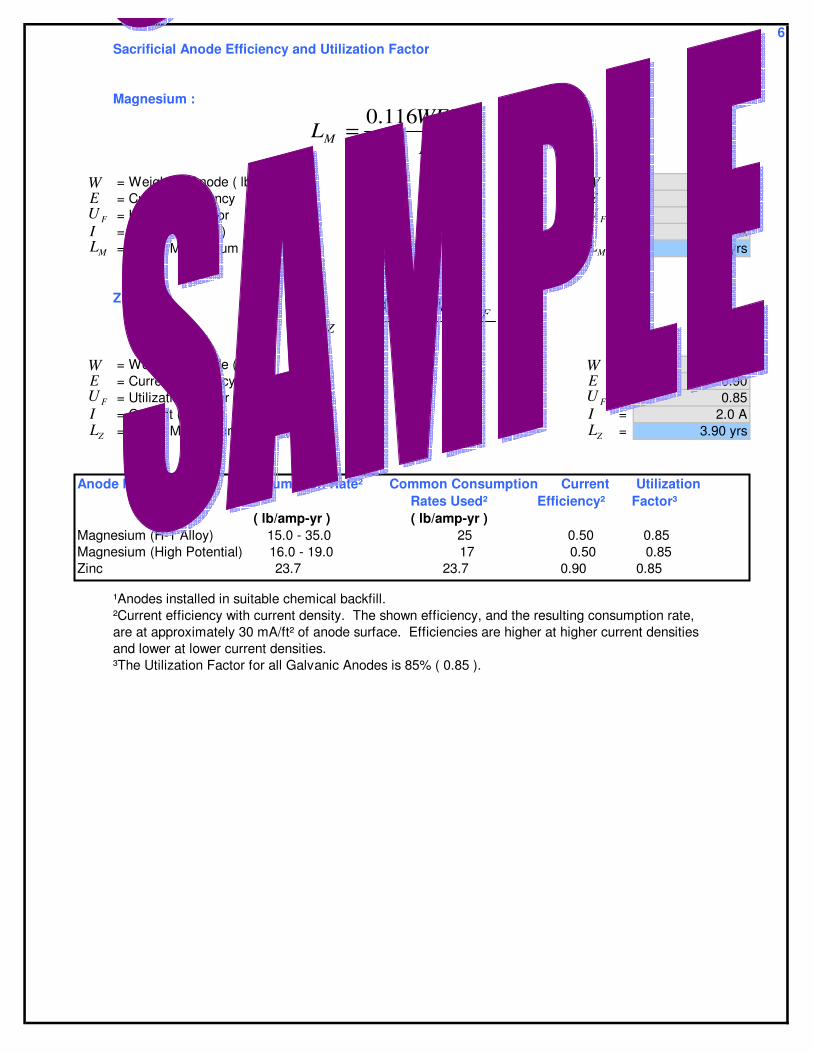
6Sacrificial Anode Efficiency and Utilization Factor
Magnesium :
= Weight of Anode ( lb ) = 240.30 lb = Current Efficiency = 0.50 = Utilization Factor = 0.85 = Current ( amps ) = 2.0 A = Life of Magnesium Anode ( yrs ) = 5.92 yrs
Zinc :
= Weight of Anode ( kg ) = 240.30 lb = Current Efficiency = 0.90 = Utilization Factor = 0.85 = Current ( amps ) = 2.0 A = Life of Magnesium Anode ( yrs ) = 3.90 yrs
¹Anodes installed in suitable chemical backfill.²Current efficiency with current density. The shown efficiency, and the resulting consumption rate,are at approximately 30 mA/ft² of anode surface. Efficiencies are higher at higher current densitiesand lower at lower current densities.³The Utilization Factor for all Galvanic Anodes is 85% ( 0.85 ).
WE
FUI
WE
FUI
ML ML
WE
FUI
WE
FUI
ZL ZL
Anode Material¹ Consumption Rate² Common Consumption Current Utilization Rates Used² Efficiency² Factor³ ( lb/amp-yr ) ( lb/amp-yr )Magnesium (H-1 Alloy) 15.0 - 35.0 25 0.50 0.85Magnesium (High Potential) 16.0 - 19.0 17 0.50 0.85Zinc 23.7 23.7 0.90 0.85
IWEU
L FZ
0424.0=
IWEU
L FM
116.0=
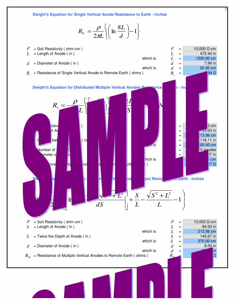
7Dwight's Equation for Single Vertical Anode Resistance to Earth - inches
= Soil Resistivity ( ohm-cm ) = 10,000 -cm = Length of Anode ( in ) = 472.44 in
which is = 1200.00 cm = Diameter of Anode ( in ) = 7.99 in
which is = 20.30 cm = Resistance of Single Vertical Anode to Remote Earth ( ohms ) = 6.84
Dwight's Equation for Distributed Multiple Vertical Anodes Resistance to Earth - inches
= Soil Resistivity ( ohm-cm ) = 10,000 -cm = Length of Anode ( in ) = 84.00 in
which is = 213.36 cm = Spacing between Anodes ( in ) = 118.11 in
which is = 300.00 cm = Number of Anodes = 10 anodes = Diameter of Anode ( in ) = 7.87 in
which is = 20.00 cm = Resistance of Multiple Vertical Anodes to Remote Earth ( ohms ) = 4.57
Dwight's Equation for Single Horizontal Vertical Anode (or Pipe) Resistance to Earth - inches
= Soil Resistivity ( ohm-cm ) = 10,000 -cm = Length of Anode ( in ) = 84.00 in
which is = 213.36 cm = Twice the Depth of Anode ( in ) = 145.67 in
which is = 370.00 cm = Diameter of Anode ( in ) = 8.00 in
which is = 20.32 in = Resistance of Multiple Vertical Anodes to Remote Earth ( ohms ) = 22.52
ρL
d
vR
ρL
d
vR
+−
= )656.0ln(2
18
ln2
NSL
dL
NLRv π
ρ
ρL
d
vR
S
N
ρL
d
vR
S
N
−+−+
++= 144
ln2
22222
LLS
LS
dSLSLL
LRH π
ρ
ρL
d
S
ρL
d
S
HR HR
−
= 18
ln2 d
LL
RV πρ
L
d
L
S
d
L
S
d

8Dwight's Equation for Distributed Multiple Horizontal Anodes Resistance to Earth - inches
where
= Soil Resistivity ( ohm-cm ) = 10,000 -cm = Spacing between Anodes ( in ) = 0.080 in
which is = 0.203 cm = Number of Anodes = 10 anodes = Resistance of One Anode ( ohms ) = 203.20 = Multiple Anode Factor = 146.48 = Resistance of Multiple Vertical Anodes to Remote Earth ( ohms ) = 2976.39
FNR
RN = )66.0ln(1 NSR
Fπ
ρ+=
ρS
ρS
F F
S
N
S
NR R
NR NR
S
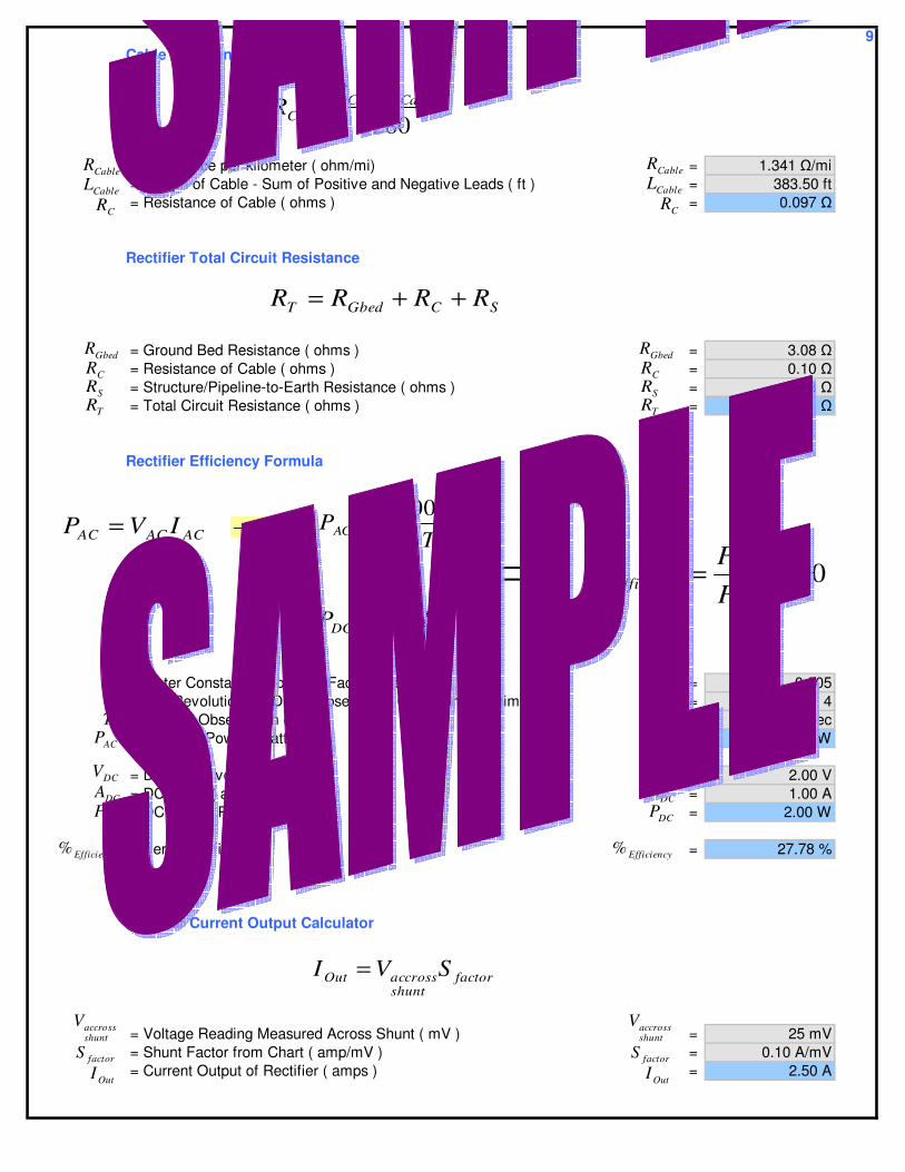
9Cable Resistance
= Resistance per kilometer ( ohm/mi) = 1.341 /mi = Length of Cable - Sum of Positive and Negative Leads ( ft ) = 383.50 ft = Resistance of Cable ( ohms ) = 0.097
Rectifier Total Circuit Resistance
= Ground Bed Resistance ( ohms ) = 3.08 = Resistance of Cable ( ohms ) = 0.10 = Structure/Pipeline-to-Earth Resistance ( ohms ) = 7.53 = Total Circuit Resistance ( ohms ) = 10.71
Rectifier Efficiency Formula
= Meter Constant ( Shown on Face of Meter ) = 0.005 = # of Revolutions of Disk ( Observe for 60 Seconds Minimum ) = 4 = Time of Observation ( sec ) = 10 sec = AC Input Power ( watts ) = 7.20 W
= DC Volts ( volts ) = 2.00 V = DC Amps ( amps ) = 1.00 A = DC Output Power ( watts ) = 2.00 W
= Percent Efficiency = 27.78 %
Rectifier Current Output Calculator
= Voltage Reading Measured Across Shunt ( mV ) = 25 mV = Shunt Factor from Chart ( amp/mV ) = 0.10 A/mV = Current Output of Rectifier ( amps ) = 2.50 A
SCGbedT RRRR ++=
GbedRCRSRTR
GbedRCRSRTR
KNT
Efficiency%
CableRCableL
CR
CableRCableL
CR
DCDCDC IVP =
ACACAC IVP =T
KNPAC
3600=
100% ×=AC
DCEfficiency P
P
ACP
DCVDCADCP
−− OR
KNT
Efficiency%
ACP
DCVDCADCP
shuntaccrossV
factorS
factorshuntaccrossOut SVI =
OutI
shuntaccrossV
factorSOutI
5280CableCable
C
LRR =

10Faraday's Law
= Consumption Rate - Electrochemical Equivalent ( lb/amp-yr ) = 20.10 lb/A-yr = Current ( amps ) = 0.875 A = Time ( yrs ) = 4.0 yrs = Weight Loss of Product ( lb ) = 70.4 lb
kg/A-yr lb/A-yr1.30 2.863.00 6.504.00 10.009.10 20.100.50 1.009.60 21.20
20.80 45.8010.70 28.6019.40 42.8033.90 74.70
¹Based on Table 2, Chapter 2, Basic Course manual,
Appalachian Underground Corrosion Short Course
Impressed Current -- # of Anodes Required
= Consumption Rate ( lb/amp-yr ) = 0.75 lb/A-yr = Desired Lifetime ( yrs ) = 20 yrs = Current Required ( amps ) = 15.00 A = Utilization Factor = 0.60 = Weight per Anode ( lb ) = 60.0 lb = # of Anodes to Use = 6.25 anodes
rounding up - use = 7 anodes
# of Anodes Required Based on Current Discharge
= Current Required ( amps ) = 14.70 A = Maximum Discharge per Anode ( amps ) = 2.50 A
* From Anode Manufacturer Data = # of Anodes to Use = 5.88 anodes
rounding up - use = 6 anodes
Lead
NickelCopper (Monovalent)ZincTin
AluminumMagnesiumIron/SteelHigh Silicon/Chromium Iron
Consumption Rate K for Various Metals¹Metal
Carbon
DesiredLquiredI Re
FactorU
Anodes#AnodeW
DesiredLquiredI Re
FactorU
Anodes#AnodeW
*Re#MD
I quiredAnodes =
quiredI Re*MD
Anodes#
quiredI Re*MD
Anodes#
Anodes#→
Anodes#→
KITWt =
KIT
tW
KIT
tW
AnodeFactor
quiredDesiredAnodes WU
IKL Re# =
K K

11Coating Resistance Calculations
where
= Diameter of Pipe ( in ) = 23.99 in = Length of Test Span ( ft ) = 5280.00 ft = Surface Area of Pipe Test Span ( ft² ) = 33,158.63 ft² = On Voltage Reading - Test Site 1 ( volts ) = -2.000 V = Off Voltage Reading - Test Site 1 ( volts ) = -0.900 V = IR Drop Voltage Difference - Test Site 1 ( volts ) = 1.100 V = On Current Reading - Test Site 1 ( amps ) = 3.000 A = Off Current Reading - Test Site 1 ( amps ) = 0.200 A = IR Drop Current Difference - Test Site 1 ( amps ) = 2.800 A = On Voltage Reading - Test Site 2 ( volts ) = -1.700 V = Off Voltage Reading - Test Site 2 ( volts ) = -0.850 V = IR Drop Voltage Difference - Test Site 2 ( volts ) = 0.850 V = On Current Reading - Test Site 2 ( amps ) = 2.800 A = Off Current Reading - Test Site 2 ( amps ) = 0.100 A = IR Drop Current Difference - Test Site 2 ( amps ) = 2.700 A = Voltage Average over Pipe Test Span ( volts ) = 0.975 V = Current over Pipe Test Span ( amps ) = 0.100 A = Resistance Pipe - to - Soil ( ohms ) = 9.750 = Effective Coating Resistance of Pipe Test Span ( ohm-ft² ) = 323,296.65 -ft²
DL
1TSEON1TSEOFF
1TSION1TSIOFF
SA
2TSEON2TSEOFF
2TSION2TSIOFF
aveECI
1TSE∆
2TSE∆
1TSI∆
2TSI∆
DL
1TSEON1TSEOFF
1TSION1TSIOFF
SA
2TSEON2TSEOFF
2TSION2TSIOFF
aveECI
1TSE∆
2TSE∆
1TSI∆
2TSI∆
SPR /
CERSPR /
CER
)()(2
)()(2
2211
2211
21
21
/TSTSTSTS
TSTSTSTS
TSTS
TSTS
C
aveSP IOFFIONIOFFION
EONEOFFEONEOFF
II
EE
IE
R−−−
−+−
=∆−∆
∆+∆
=∆
=
SPSCE RAR /=
LDAS π=

122-Wire Current Test over Pipe Test Span
Cathodic Protection Level 2 Training Manual - NACE pg. 4:58
where
= Diameter of Pipe ( in ) = 30.00 in = Thickness of Pipe Wall ( in ) = 0.375 in = Length of Pipe Test Span ( ft ) = 200.00 ft = Resistance of Pipe per meter from Table ( µohm/ft ) = 2.44 µ/ft = Resistance of Pipe Test Span ( ohms ) = 0.00048800 = Measured Voltage Drop over Pipe Test Span ( volts ) = 0.00017 V = Calculated Current over Pipe Test Span ( amps ) = 0.348 A
Table of Steel Pipe Resistances per Length¹²³Pipe Size
( in ) ( in ) ( cm ) ( in ) ( cm ) ( lb/ft ) ( kg/m ) ( µ/ft )2 2.35 0.925 0.154 0.061 3.65 5.43 76.204 4.50 1.772 0.237 0.093 10.80 16.07 26.806 6.62 2.606 0.280 0.110 16.00 28.28 15.208 8.62 3.394 0.322 0.127 28.60 42.56 10.1010 10.75 4.232 0.365 0.144 40.50 60.27 7.1312 12.75 5.020 0.375 0.148 46.60 73.81 5.8214 14.00 5.512 0.375 0.148 54.60 81.26 5.2916 16.00 6.299 0.375 0.148 62.60 93.16 4.6118 18.00 7.087 0.375 0.148 70.60 105.07 4.0920 20.00 7.874 0.375 0.148 78.60 116.97 3.6822 22.00 8.661 0.375 0.148 86.60 128.88 3.3424 24.00 9.449 0.375 0.148 94.60 140.78 3.0626 26.00 10.236 0.375 0.148 102.60 152.69 2.8228 28.00 11.024 0.375 0.148 110.60 164.59 2.6230 30.00 11.811 0.375 0.148 118.70 176.65 2.4432 32.00 12.598 0.375 0.148 126.60 188.41 2.2834 34.00 13.386 0.375 0.148 134.60 200.31 2.1536 36.00 14.173 0.375 0.148 142.60 212.22 2.03
¹ Conversions based on 1in = 2.54cm and 1ft = 0.3048m.² Based on steel density of 489 lbs/ft³ ( 7832 kg/m³ ) and steel resistivity of 18 µ/cm.³ R = 16.061 x resistivity in µ/cm = Resistance of 1 ft of Weight per foot of pipe in µ.
8.017.487.056.66
10.9610.046.258.60
17.3615.1213.4212.07
46.8733.1423.3916.09
Resistance( µ/m )256.8487.93
Outside Diameter Wall Thickness Weight
PS
PSPS R
EI
∆=
PSL
PPSPS RLR =
PRPSR
PSE∆PSI
PSLPRPSR
PSE∆PSI
Dt
Dt

134-Wire Current Test over Pipe Test Span
Cathodic Protection Level 2 Training Manual - NACE pg. 4:60
where
= Voltage Drop with Current Applied ( volts ) = 0.00508 V = Voltage Drop with Current Not Applied ( volts ) = 0.00017 V = Applied Current to Pipe Test Span ( amps ) = 10.00 A = Calibration Factor ( amp/mV ) = 2.037 A/mV = Measured Voltage Drop over Pipe Test Span ( volts ) 0.00017 V = Calculated Current over Pipe Test Span ( amps ) = 0.346 A
ONEOFFE
AIK
PSI
OFFON
A
EEI
K−
=PSPS EKI ∆×=
ONEOFFE
AIK
PSIPSE∆ PSE∆

14Conductance
units are in Siemens ( S ) or microSiemens ( µS )
units of Siemen ( S ) =
= Resistance ( ohms ) = 9.750 = Conductance ( S ) = 0.103 S
Resistivity Calculations
* Area may be Cross - Sectional Area of any material ( i.e. Pipe, Soil, Electrolye, etc. )* For Soil Box Measurements A & L are made to be the same so they cancel out.
Cathodic Protection Level 1 Training Manual - NACE 2000 pg 1:4
= Area of Cross-Section ( in² ) = 155.00 in²which is = 1000.00 cm²
= Resistance ( ohms ) = 200.000 = Length ( in ) = 1200.00 in
which is = 472.44 cm = Resistivity ( ohm-cm ) = 423.332 -cm
Wenner Method
Cathodic Protection Level 1 Training Manual - NACE 2000 pg 4:28
= Spacing of the Pins ( in ) = 1.58 inwhich is = 4.00 cm
= Resistance Measured - shown on Instrument ( ohms ) = 450.00 = Resistivity of Measured Medium ( ohm-cm ) = 11309.734 -cm
RC
1=Ω1
CR
CR
LRA=ρ
ρ
RL
ρ
RL
aRπρ 2=a
Rρ
a
Rρ
A AA
L
a

15Layer Resistivity Calculations
Cathodic Protection Level 2 Training Manual - NACE 2000 pg 4:67
Parallel Resistance Formula
Layer 1 Layer 2 Layer 3
= Layer 1 Spacing - Depth Measured ( in ) = 62.64 inwhich is = 159.11 cm
= Layer 1 Resistance Measured - shown on Instrument ( ohms ) = 10.00 = Layer 1 Average Resistivity ( ohm-cm ) = 9996.90 -cm = Layer 1 Spacing - Depth Measured ( cm ) = 159.11 cm
which is = 62.64 in = Layer 1 Resistance Measured - shown on Instrument ( ohms ) = 10.00 = Layer 1 Resistivity ( ohm-cm ) = 9996.90 -cm
= Layer 2 Spacing - Total Depth Measured ( in ) = 125.28 inwhich is = 318.21 cm
= Layer 2 Resistance Measured - shown on Instrument ( ohms ) = 7.40 = Layer 2 Average Resistivity ( ohm-cm ) = 5824.97 -cm = Layer 2 Spacing - Layer Depth Measured ( cm ) = 159.11 cm
which is = 62.64 in = Layer 2 Parallel Resistance ( ohms ) = 28.46 = Layer 2 Resistivity ( ohm-cm ) = 28452.714 -cm
= Layer 3 Spacing - Total Depth Measured ( in ) = 187.92 inwhich is = 477.32 cm
= Layer 3 Resistance Measured - shown on Instrument ( ohms ) = 3.10 = Layer 3 Average Resistivity ( ohm-cm ) = 9297.12 -cm = Layer 3 Spacing - Layer Depth Measured ( cm ) = 159.11 cm
which is = 62.64 in = Layer 3 Parallel Resistance ( ohms ) = 5.33
ba
bac RR
RRR
−=
layerlayerlayer
layer
layer
avg
RS
RR
SS
RS
111
11
11
111
2
2
πρ
πρ
=
=
=
=
layerlayerlayer
layer
layer
avg
RS
RRRR
R
SSS
RS
222
21
212
122
222
2
2
πρ
πρ
=−
=
−=
=
layerlayerlayer
layer
layer
avg
RS
RRRR
R
SSS
RS
333
32
323
233
333
2
2
πρ
πρ
=−
=
−=
=
layerS1
layerR1
layer1ρ
avg1ρ
avg2ρlayerS 2
layerR2
layer2ρ
avg3ρlayerS3
layerR3
layer3ρ
layerS1
layerR1
layer1ρ
avg1ρ
avg2ρlayerS 2
layerR2
layer2ρ
avg3ρlayerS3
layerR3
layer3ρ
2R
3R
2R
3R
1R 1R
1S
3S
1S
3S
2S 2S
1S
2S
3S
layerS1
layerS 2
layerS 3

= Layer 3 Resistivity ( ohm-cm ) = 5333.230 -cm16
Shunt Types and Values
Shunt Value
Shunt Factor
Amps mV Ohms A/mV
5 50 0.01 0.125 25 0.001 150 50 0.001 11 50 0.05 0.022 50 0.025 0.043 50 0.017 0.064 50 0.0125 0.085 50 0.01 0.1
10 50 0.005 0.215 50 0.0033 0.320 50 0.0025 0.425 50 0.002 0.530 50 0.0017 0.650 50 0.001 160 50 0.0008 1.275 50 0.00067 1.5100 50 0.0005 2
5 50 0.01 0.1
2 200 0.1 0.010.5 50 0.1 0.018 80 0.01 0.1
25 25 0.001 1Yellow ( MCM )Orange ( MCM )
Agra - MesaCott or MCMRed ( MCM )Red ( Cott )
SWSWSWJ.B Type
SWSWSWSW
SW or CPSW or CPSW or CPSW
SOSW or CPSW or CPSW or CP
Shunt Rating
Holloway TypeRSSS
layerR3
layer3ρlayerR3
layer3ρ

17Rudenberg Formula
= Resistivity of Earth ( ohm-cm ) = 1000.00 -cm = Length of Anode in Earth ( in ) = 60.00 in
which is = 5.00 ft = Distance from Anode ( ft ) = 20.000 ft = Current of Ground Anode ( amps ) = 2.0 A = Voltage Potential at Distance x caused by Ground Anode Current ( volts ) = 0.520 V
if x > 10y then
xV
ρy
xI
xI
Vxρ0052.0=
xV
ρy
xI
++=
x
xyy
yI
Vx
22
10log038.0π
ρ
y

18Nernst Equation
= Standard State Half - Cell Electrode Potential - from table ( volts ) = -0.763 V = Universal Gas Constant = 8.31434 ( J/mol·K ) = 8.31434 J/mol·K = Absolute Temperature ( K ) ¹ = 298.15 K = Number of Valence Electrons Transferred - from table = 2 = Faraday's Constant = 96,485.309 ( C/g·mol ) = 96485.31 C/g·mol = Activity of Metal Ions in Solution ² = 0.71 = Activity of the Metal ( = 1 for pure metal ) = 1 = Electrode Potential in Existing Solution ( volts ) = -0.827 V
¹ Absolute Temperature is -273.15 ºC. Standard Conditions for pure metals in the emf series are based on one unit activity of metal ions in the electrolyte at 25 ºC with no impurities in the metal or electrolyte and with reference to a standard hydrogen electrode.
² Activity Coefficients can be found in Chemistry or Engineering handbooks at a molar concentration of 0.01 mol.
Valence of Common Metals
Half-Cell Metal Valence
Au/Au++ Aluminum 3Pt/Pt++ Copper 2Cu/Cu++ Copper 1H2/2H++ Iron 3Pb/Pb++ Iron 2Ni/Ni++ Lead 4Fe/Fe++ Lead 2Zn/Zn++ Zinc 2Al/Al++Mg/Mg++
* Standard Hydrogen Electrode ( SHE )
-0.20 -0.15-0.20 -0.15
-0.50 -0.45-0.20 -0.15
-0.20 to -0.50 -0.015 to -0.45-0.50 -0.45
-1.05 -1.00 -0.50 to -0.80 -0.45 to -0.75
-1.60 to -1.75 -1.55 to -1.70-1.10 -1.05
Practical Galvanic Series in Seawater
MetalStandard Electrode
Potential Eº ( volts ) vs. SHE*
[ ][ ]
+=
+
M
neM
aa
nFRT
EE ln0
0ERTnF
neMa +
Ma
0ERTnF
neMa +
MaMaE E


![s E O 8 r-i (HEIR • Bar] IR o CO +4' e Ill m n Ina e o fie rtÐkÞ ......2016/03/07 · 8 r-i (HEIR • Bar] IR o CO +4' e Ill m n Ina e o fie rtÐkÞ](https://img.pdfslide.us/doc/110x75/60dfa5b4fac2a7360844f6f4/s-e-o-8-r-i-heir-a-bar-ir-o-co-4-e-ill-m-n-ina-e-o-fie-rtk-20160307.jpg)