Embed Size (px)
Citation preview
Swiss Timing LTD Phone +41 32 488 36 11 P.O. Box 138, Rue de l’Envers 1 [email protected] CH-2606 Corgémont - Switzerland www.swisstiming.com
& StartTime V – ELECTRONIC START SYSTEM
USER’S MANUAL
3481.560.02 l Version 1.0 l July 2015
Caution and safety precautions
Never use any other charger than the supplied or a type approved by Swiss Timing. This could destroy the
battery, cause damage to unit, and possible cause personal injury due to fire or/and electrical shock. Never bypass a power cord ground lead by breaking off the ground pin, or by using inappropriate extension
cords or adapters. Never plug a power cord into the AC power source until you have made sure that all installation, cabling and
power levels, are proper, and that the applicable procedures in this manual have been followed. Protect the equipment against splashing, rain and excessive sun rays. Never use the device if it is damaged or insecure. Verify the selection of the power distribution. Verify that the voltage quoted on the rating plate is the same as your voltage. Connect the appliance only to
power sockets with protective earth. The use of incorrect connection voids warranty. This program may be modified at any time without prior notification. Do not open the case; there is nothing that needs servicing inside it. Nevertheless, if the case must be
opened, you must call for some qualified personnel. The power supply cable must be disconnected before opening the case.
During the transport of all Swiss Timing equipment delivered with a reusable carry case, the said case should be used at all times. This is imperative to limit the damage, such as shocks or vibration that can be caused to the units during transport.
The same cases should also be used when returning equipment to Swiss Timing for repair. Swiss Timing reserves the right to refuse all guarantees if this condition is not fulfilled.
If the installation includes a horn, be sure to maintain a sufficient security distance from the public.
Documentation Updates Swiss Timing SA reserves the right to make improvements in the products described in this documentation at any time without prior notice. Furthermore, Swiss Timing SA reserves the right to revise this documentation in its content at any time and without any obligation to notify any person or organization of such revision. Disclaimer The information provided in this documentation has been obtained from sources believed to be reliable, accurate and current. However, Swiss Timing SA makes no representation or warranty, express or implied, with respect, but not limited to, the completeness, accuracy, correctness and actuality of the content of this documentation. Swiss Timing SA specifically disclaims any implied warranty of merchantability, quality and/or fitness for any particular purpose. Swiss Timing SA shall not be liable for errors contained in this documentation or for incidental or consequential damages in connection with the supply, performance or use of this documentation. Environment
This symbol indicates that this product should not be disposed with household waste. It has to be returned to a local authorized collection system. By following this procedure you will contribute to the protection of the environment and human health. The recycling of the materials will help to conserve natural resources.
Copyright © Swiss Timing SA All rights reserved. This documentation may not, as a whole or in part, be copied, translated, reproduced, transmitted or reduced and/or stored to any electronic medium or machine-readable form without the prior written consent of Swiss Timing SA
ELECTRONIC START SYSTEM / E-GUN & StartTime V
Swiss Timing LTD Phone +41 32 488 36 11 P.O. Box 138, Rue de l’Envers 1 [email protected] CH-2606 Corgémont - Switzerland www.swisstiming.com
TABLE OF CONTENTS
1 INTRODUCTION ................................................................................................................... 1
1.1 Operation principle ........................................................................................................... 1
1.2 Starting equipment with Start & Microphone unit (SMU) ............................................... 2
1.3 Starting equipment with .................................................................................. 2
1.4 Front panel ........................................................................................................................ 3
1.5 Rear panel and cover ........................................................................................................ 4
1.6 Start & Microphone unit (SMU) ........................................................................................ 4
1.7 ........................................................................................................................... 5
2 INSTALLATION ..................................................................................................................... 6
2.1 Connecting the installation ............................................................................................... 6
2.1.1 Connections overview ........................................................................................ 6
2.1.2 External loudspeakers connection ..................................................................... 7
2.1.3 Extension cables ................................................................................................. 7
2.2 Operation .......................................................................................................................... 8
2.2.1 Stand alone operation with TIMER (Quantum, ARES) ....................................... 8
2.2.2 Independent operation ...................................................................................... 9
2.2.3 Power ON sequence ......................................................................................... 10
2.2.4 Audio levels ...................................................................................................... 10
2.2.5 Battery level ..................................................................................................... 10
3 GETTING STARTED ............................................................................................................. 11
3.1 First use ........................................................................................................................... 11
3.2 Main menu ...................................................................................................................... 11
3.3 Setup menu ..................................................................................................................... 12
3.3.1 Audio menu ...................................................................................................... 12
3.3.2 Sport configuration menu ................................................................................ 12
3.3.3 Setup menu ...................................................................................................... 13
3.3.4 Summary setup menu ...................................................................................... 14
3.3.5 System menu .................................................................................................... 15
3.3.6 Factory settings ................................................................................................ 15
4 ELECTRICAL PROPERTIES .................................................................................................... 16
Swiss Timing LTD Phone +41 32 488 36 11 P.O. Box 138, Rue de l’Envers 1 [email protected] CH-2606 Corgémont - Switzerland www.swisstiming.com
4.1 Power supply ................................................................................................................... 16
4.2 Connectors pinning ......................................................................................................... 16
5 PROPERTIES ...................................................................................................................... 17
5.1 Specifications StartTime V .............................................................................................. 17
5.2 Specifications .................................................................................................. 17
5.3 Specifications Start & Microphone unit (SMU) ............................................................... 17
6 OPTIONS ........................................................................................................................... 18
6.1 Auxiliary flash .................................................................................................................. 18
6.2 External loudspeaker....................................................................................................... 18
7 MAINTENANCE AND PROTECTION ..................................................................................... 19
7.1 Fuses ................................................................................................................................ 19
8 APPENDIX ......................................................................................................................... 20
8.1 Abbreviations and symbols ............................................................................................. 20
8.2 Version history ................................................................................................................ 20
ELECTRONIC START SYSTEM / E-GUN & StartTime V
Version 1.0 3481.560.02 Page 1
1 INTRODUCTION
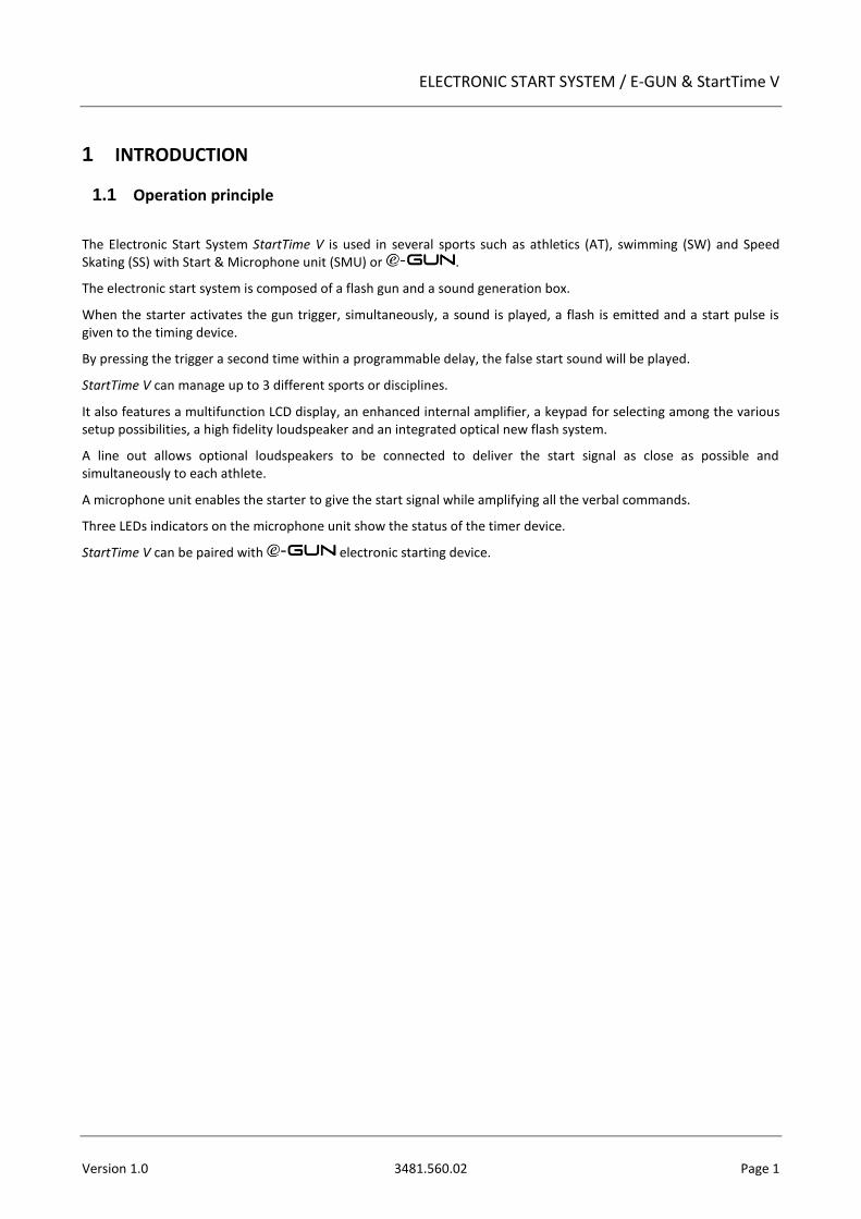
1.1 Operation principle
The Electronic Start System StartTime V is used in several sports such as athletics (AT), swimming (SW) and Speed Skating (SS) with Start & Microphone unit (SMU) or .
The electronic start system is composed of a flash gun and a sound generation box.
When the starter activates the gun trigger, simultaneously, a sound is played, a flash is emitted and a start pulse is given to the timing device.
By pressing the trigger a second time within a programmable delay, the false start sound will be played.
StartTime V can manage up to 3 different sports or disciplines.
It also features a multifunction LCD display, an enhanced internal amplifier, a keypad for selecting among the various setup possibilities, a high fidelity loudspeaker and an integrated optical new flash system.
A line out allows optional loudspeakers to be connected to deliver the start signal as close as possible and simultaneously to each athlete.
A microphone unit enables the starter to give the start signal while amplifying all the verbal commands.
Three LEDs indicators on the microphone unit show the status of the timer device.
StartTime V can be paired with electronic starting device.
Page 2 3481.560.02 Version 1.0
1.2 Starting equipment with Start & Microphone unit (SMU)
1x Electronic start system StartTime V (3481.770) 1x Start & Microphone unit (3481.772) 1x Charger 12VDC-2A (3418.753) 1x Cable AC power 2m depending on the country
Euro and CH (9051.3569) UK (9051.3570) US (9051.3571) AUS (9051.3572)
1x User’s Manual (DOC3481.560)
1.3 Starting equipment with
1x Electronic Start System StartTime V (3481.770) 1x Electronic Start Device (3481.704) 1x Headset (9051.8155) 1x Charger 12VDC-2A (3418.753) 1x Cable AC power 2m depending on the country
Euro and CH (9051.3569) UK (9051.3570) US (9051.3571) AUS (9051.3572)
1x Transportation case (9072.6001) 1x User’s Manual (DOC3481.560)
ELECTRONIC START SYSTEM / E-GUN & StartTime V
Version 1.0 3481.560.02 Page 3
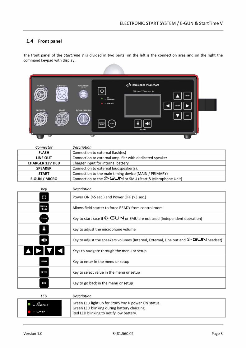
1.4 Front panel
The front panel of the StartTime V is divided in two parts: on the left is the connection area and on the right the command keypad with display.
Connector Description
FLASH Connection to external flash(es)
LINE OUT Connection to external amplifier with dedicated speaker
CHARGER 12V DCD Charger input for internal battery
SPEAKER Connection to external loudspeaker(s).
START Connection to the main timing device (MAIN / PRIMARY)
E-GUN / MICRO Connection to the or SMU (Start & Microphone Unit)
Key Description
Power ON (>5 sec.) and Power OFF (>3 sec.)
Allows field starter to force READY from control room
Key to start race if or SMU are not used (Independent operation)
Key to adjust the microphone volume
Key to adjust the speakers volumes (Internal, External, Line out and headset)
Keys to navigate through the menu or setup
Key to enter in the menu or setup
Key to select value in the menu or setup
Key to go back in the menu or setup
LED Description
Green LED light up for StartTime V power ON status. Green LED blinking during battery charging. Red LED blinking to notify low battery.
Page 4 3481.560.02 Version 1.0
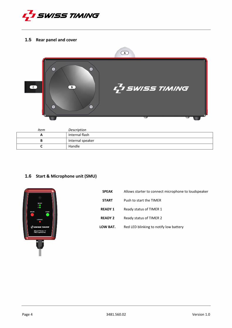
1.5 Rear panel and cover
Item Description
A Internal flash
B Internal speaker
C Handle
1.6 Start & Microphone unit (SMU)
SPEAK Allows starter to connect microphone to loudspeaker
START Push to start the TIMER
READY 1 Ready status of TIMER 1
READY 2 Ready status of TIMER 2
LOW BAT. Red LED blinking to notify low battery
ELECTRONIC START SYSTEM / E-GUN & StartTime V
Version 1.0 3481.560.02 Page 5
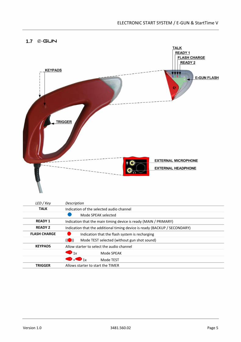
1.7
LED / Key Description
TALK Indication of the selected audio channel
Mode SPEAK selected
READY 1 Indication that the main timing device is ready (MAIN / PRIMARY)
READY 2 Indication that the additional timing device is ready (BACKUP / SECONDARY)
FLASH CHARGE Indication that the flash system is recharging
(( )) Mode TEST selected (without gun shot sound)
KEYPADS Allow starter to select the audio channel
1x Mode SPEAK
+ 1x Mode TEST
TRIGGER Allows starter to start the TIMER
Page 6 3481.560.02 Version 1.0
2 INSTALLATION
2.1 Connecting the installation
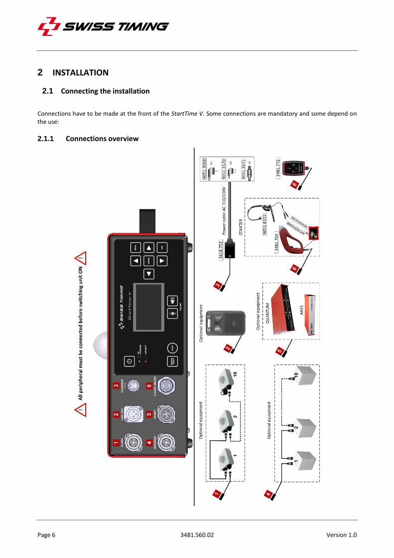
Connections have to be made at the front of the StartTime V. Some connections are mandatory and some depend on the use:
2.1.1 Connections overview
ELECTRONIC START SYSTEM / E-GUN & StartTime V
Version 1.0 3481.560.02 Page 7
2.1.2 External loudspeakers connection
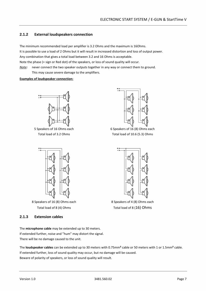
The minimum recommended load per amplifier is 3.2 Ohms and the maximum is 16Ohms.
It is possible to use a load of 2 Ohms but it will result in increased distortion and loss of output power.
Any combination that gives a total load between 3.2 and 16 Ohms is acceptable.
Note the phase (+ sign or Red dot) of the speakers, or loss of sound quality will occur.
Note: never connect the two speaker outputs together in any way or connect them to ground.
This may cause severe damage to the amplifiers.
Examples of loudspeaker connection:
5 Speakers of 16 Ohms each 6 Speakers of 16 (8) Ohms each
Total load of 3.2 Ohms Total load of 10.6 (5.3) Ohms
8 Speakers of 16 (8) Ohms each 8 Speakers of 4 (8) Ohms each
Total load of 8 (4) Ohms Total load of 8 (16) Ohms
2.1.3 Extension cables
The microphone cable may be extended up to 30 meters.
If extended further, noise and ”hum” may distort the signal.
There will be no damage caused to the unit.
The loudspeaker cables can be extended up to 30 meters with 0.75mm² cable or 50 meters with 1 or 1.5mm² cable.
If extended further, loss of sound quality may occur, but no damage will be caused.
Beware of polarity of speakers, or loss of sound quality will result.
Page 8 3481.560.02 Version 1.0
2.2 Operation
2.2.1 Stand alone operation with TIMER (Quantum, ARES)
1. Connect or SMU to E-GUN/MICRO
2. Connect the cable from TIMER to START.
3. Turn the unit ON by pressing the key (5sec.).
SMU : LEDs are tested.
: LEDs are tested.
4. Select sport (Athletics, Swimming, Speed Skating or Custom).
After 5 seconds, the sport will be automatically selected based on the last use.
SMU : STV power ON status Green LED light up and red LED SPEAK in the microphone should be lit.
: STV power ON status Green LED light up.
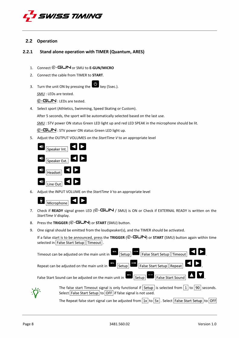
5. Adjust the OUTPUT VOLUMES on the StartTime V to an appropriate level
Speaker Int.
Speaker Ext.
Headset
Line Out
6. Adjust the INPUT VOLUME on the StartTime V to an appropriate level
Microphone
7. Check if READY signal green LED ( / SMU) is ON or Check if EXTERNAL READY is written on the StartTime V display.
8. Press the TRIGGER ( ) or START (SMU) button.
9. One signal should be emitted from the loudspeaker(s), and the TIMER should be activated.
If a false start is to be announced, press the TRIGGER ( ) or START (SMU) button again within time
selected in False Start Setup Timeout .
Timeout can be adjusted on the main unit in Setup False Start Setup Timeout .
Repeat can be adjusted on the main unit in Setup False Start Setup Repeat .
False Start Sound can be adjusted on the main unit in Setup False Start Sound .
The false start Timeout signal is only functional if Setup is selected from 1 to 90 seconds.
Select False Start Setup to OFF if false signal is not used.
The Repeat false start signal can be adjusted from 1x to 5x . Select False Start Setup to OFF
ELECTRONIC START SYSTEM / E-GUN & StartTime V
Version 1.0 3481.560.02 Page 9
if false signal is not used.
2.2.2 Independent operation
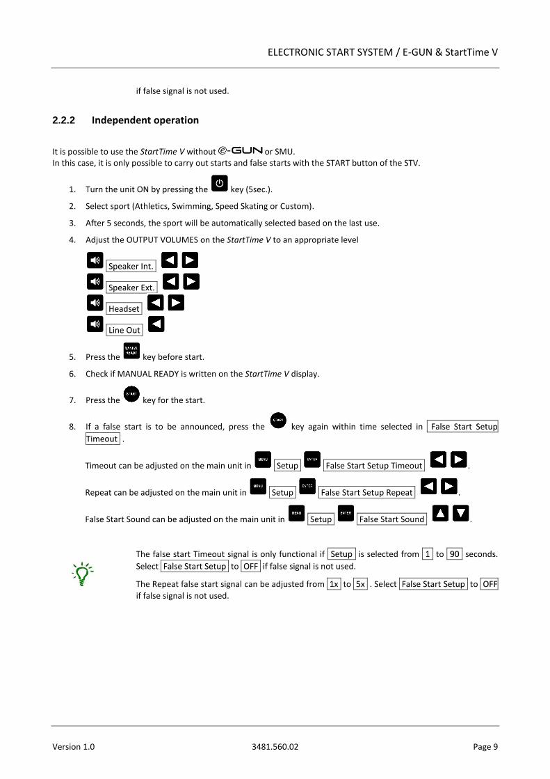
It is possible to use the StartTime V without or SMU. In this case, it is only possible to carry out starts and false starts with the START button of the STV.
1. Turn the unit ON by pressing the key (5sec.).
2. Select sport (Athletics, Swimming, Speed Skating or Custom).
3. After 5 seconds, the sport will be automatically selected based on the last use.
4. Adjust the OUTPUT VOLUMES on the StartTime V to an appropriate level
Speaker Int.
Speaker Ext.
Headset
Line Out
5. Press the key before start.
6. Check if MANUAL READY is written on the StartTime V display.
7. Press the key for the start.
8. If a false start is to be announced, press the key again within time selected in False Start Setup
Timeout .
Timeout can be adjusted on the main unit in Setup False Start Setup Timeout .
Repeat can be adjusted on the main unit in Setup False Start Setup Repeat .
False Start Sound can be adjusted on the main unit in Setup False Start Sound .
The false start Timeout signal is only functional if Setup is selected from 1 to 90 seconds.
Select False Start Setup to OFF if false signal is not used.
The Repeat false start signal can be adjusted from 1x to 5x . Select False Start Setup to OFF
if false signal is not used.
Page 10 3481.560.02 Version 1.0
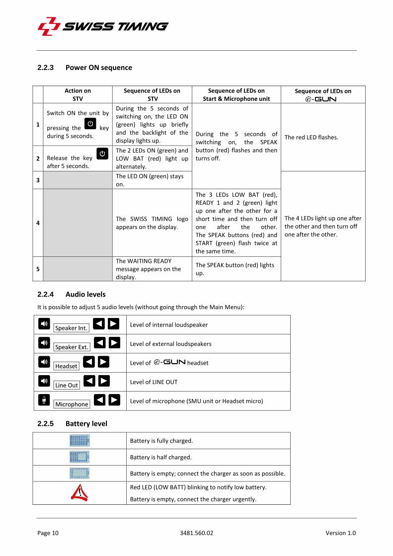
2.2.3 Power ON sequence
Action on STV
Sequence of LEDs on STV
Sequence of LEDs on Start & Microphone unit
Sequence of LEDs on
1
Switch ON the unit by
pressing the key during 5 seconds.
During the 5 seconds of switching on, the LED ON (green) lights up briefly and the backlight of the display lights up.
During the 5 seconds of switching on, the SPEAK button (red) flashes and then turns off.
The red LED flashes.
2 Release the key after 5 seconds.
The 2 LEDs ON (green) and LOW BAT (red) light up alternately.
3
The LED ON (green) stays on.
The 4 LEDs light up one after the other and then turn off one after the other.
4
The SWISS TIMING logo appears on the display.
The 3 LEDs LOW BAT (red), READY 1 and 2 (green) light up one after the other for a short time and then turn off one after the other. The SPEAK buttons (red) and START (green) flash twice at the same time.
5
The WAITING READY message appears on the display.
The SPEAK button (red) lights up.
2.2.4 Audio levels
It is possible to adjust 5 audio levels (without going through the Main Menu):
Speaker Int. Level of internal loudspeaker
Speaker Ext. Level of external loudspeakers
Headset Level of headset
Line Out Level of LINE OUT
Microphone Level of microphone (SMU unit or Headset micro)
2.2.5 Battery level
Battery is fully charged.
Battery is half charged.
Battery is empty; connect the charger as soon as possible.
Red LED (LOW BATT) blinking to notify low battery.
Battery is empty, connect the charger urgently.
ELECTRONIC START SYSTEM / E-GUN & StartTime V
Version 1.0 3481.560.02 Page 11
3 GETTING STARTED
3.1 First use
Read chapter 3, select desired configuration and connect the StartTime V charger.
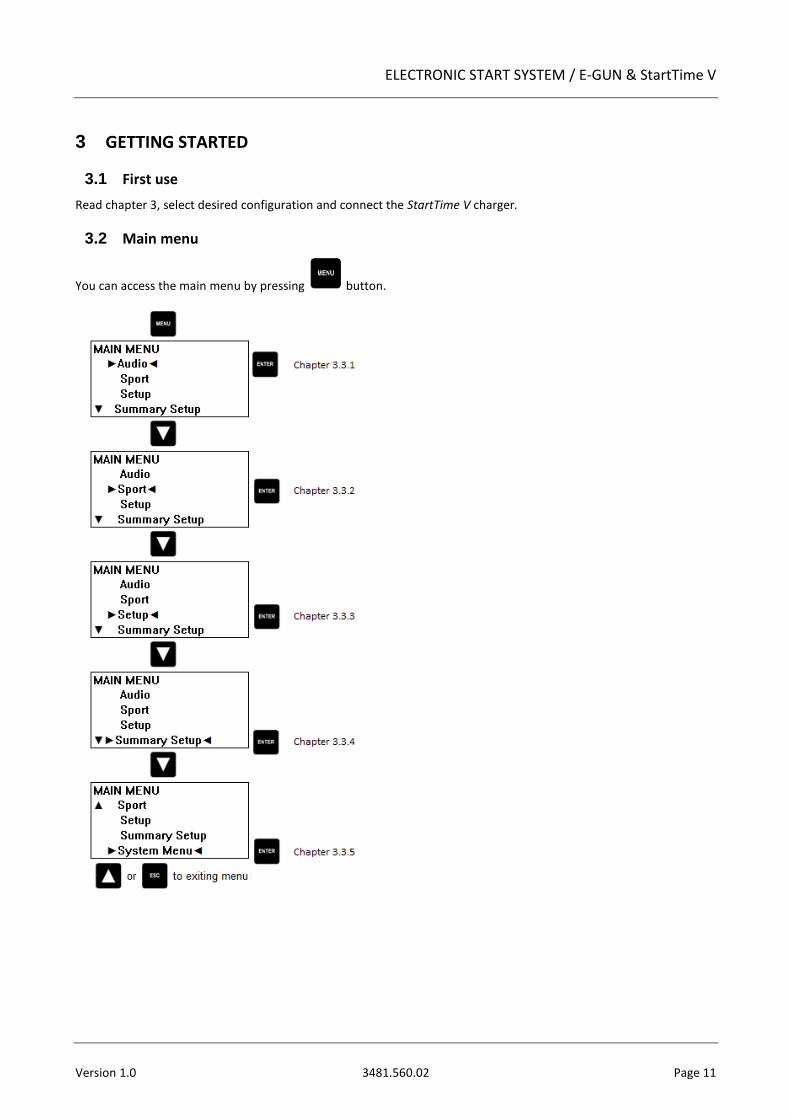
3.2 Main menu
You can access the main menu by pressing button.
Page 12 3481.560.02 Version 1.0
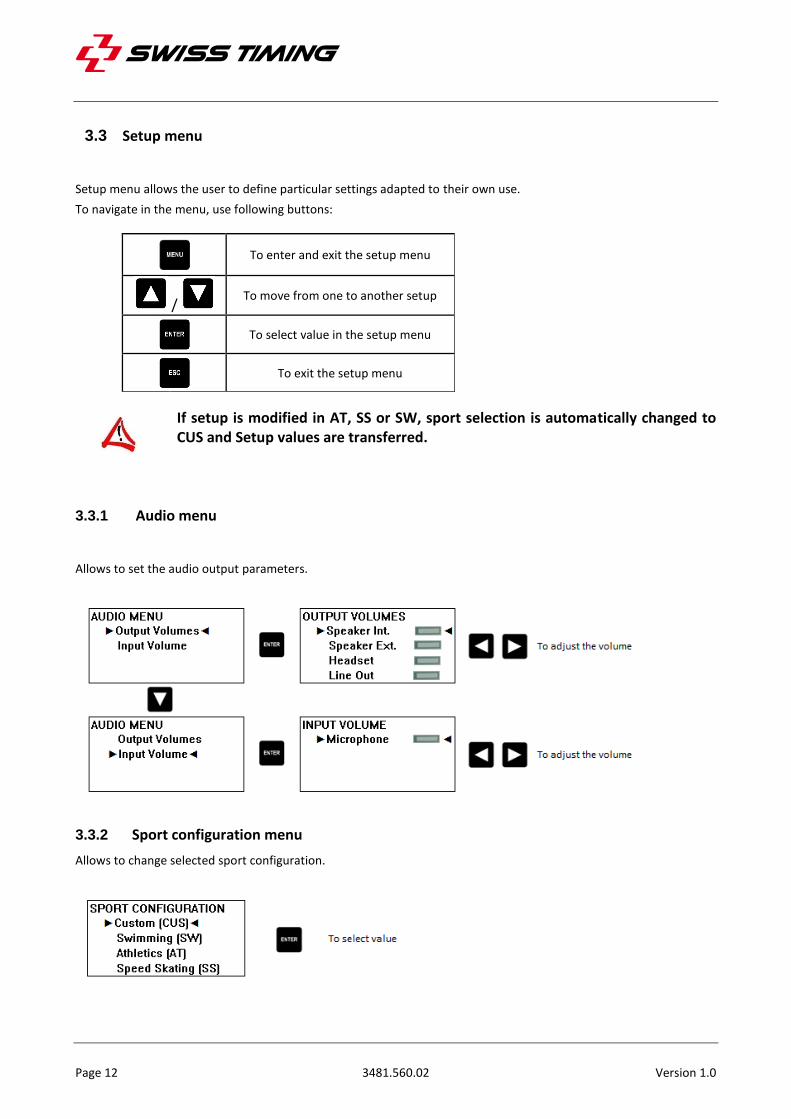
3.3 Setup menu
Setup menu allows the user to define particular settings adapted to their own use.
To navigate in the menu, use following buttons:
To enter and exit the setup menu
/ To move from one to another setup
To select value in the setup menu
To exit the setup menu
If setup is modified in AT, SS or SW, sport selection is automatically changed to CUS and Setup values are transferred.
3.3.1 Audio menu
Allows to set the audio output parameters.
3.3.2 Sport configuration menu
Allows to change selected sport configuration.
ELECTRONIC START SYSTEM / E-GUN & StartTime V
Version 1.0 3481.560.02 Page 13
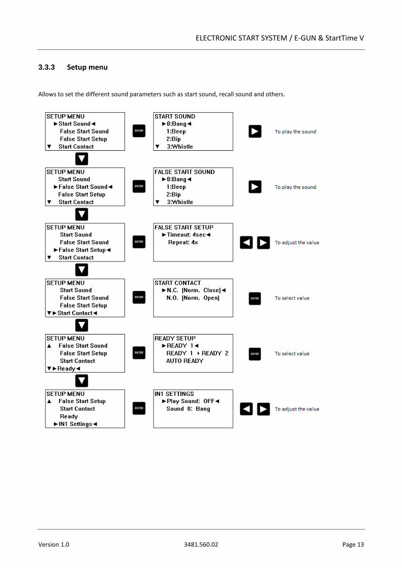
3.3.3 Setup menu
Allows to set the different sound parameters such as start sound, recall sound and others.
Page 14 3481.560.02 Version 1.0
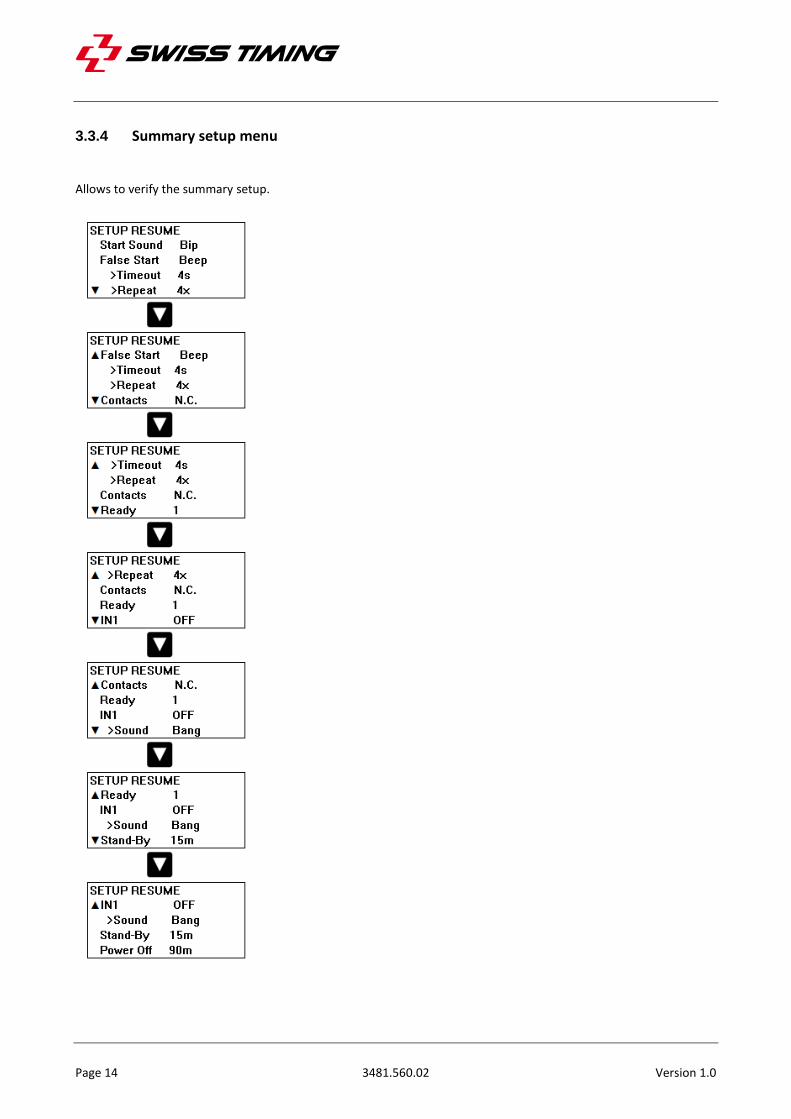
3.3.4 Summary setup menu
Allows to verify the summary setup.
ELECTRONIC START SYSTEM / E-GUN & StartTime V
Version 1.0 3481.560.02 Page 15
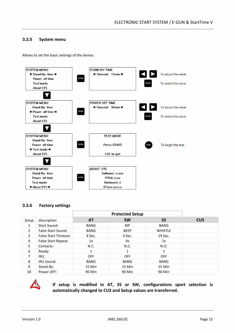
3.3.5 System menu
Allows to set the basic settings of the device.
3.3.6 Factory settings
Protected Setup
Setup Description AT SW SS CUS 1 Start Sound: BANG BIP BANG
2 False Start Sound: BANG BEEP WHISTLE
3 False Start Timeout: 4 Sec. 4 Sec. 19 Sec.
4 False Start Repeat: 1x 4x 1x
5 Contacts: N.C. N.C. N.O.
6 Ready: 1 1 1
7 IN1: OFF OFF OFF
8 IN1 Sound: BANG BANG BANG
9 Stand-By: 15 Min 15 Min 15 Min
10 Power OFF: 90 Min 90 Min 90 Min
If setup is modified in AT, SS or SW, configurations sport selection is automatically changed to CUS and Setup values are transferred.
Page 16 3481.560.02 Version 1.0
4 ELECTRICAL PROPERTIES
4.1 Power supply
Use only the original charger supplied by . If you do not use the original charger, it may destroy the battery, cause damage to the unit, and possibly cause personal injury due to fire or/and electrical shock.
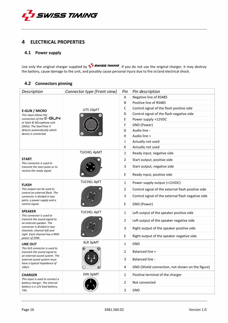
4.2 Connectors pinning
Description Connector type (Front view) Pin Pin description
E-GUN / MICRO This input allows the
connection of the or Start & Microphone unit (SMU). The StartTime V detects automatically which device is connected.
UTS 10pFT
A Negative line of RS485
B Positive line of RS485
C Control signal of the flash positive side
D Control signal of the flash negative side
E Power supply +12VDC
F GND (Power)
G Audio line -
H Audio line +
J Actually not used
K Actually not used
START This connector is used to transmit the start pulse or to receive the ready signal.
TUCHEL 4pMT
1 Ready input, negative side
2 Start output, positive side
3 Start output, negative side
E Ready input, positive side
FLASH This output can be used to control an external flash. The connector is divided in two parts, a power supply and a control signal.
TUCHEL 4pFT
1 Power supply output (+12VDC)
2 Control signal of the external flash positive side
3 Control signal of the external flash negative side
E GND (Power)
SPEAKER This connector is used to transmit the sound signal to an external speaker. The connector is divided in two channels: channel left and right. Each channel has a RMS power of 20W.
TUCHEL 4pFT
1 Left output of the speaker positive side
2 Left output of the speaker negative side
3 Right output of the speaker positive side
E Right output of the speaker negative side
LINE OUT This XLR connector is used to transmit the sound signal to an external sound system. The external sound system must have a typical impedance of
10k.
XLR 3pMT
1 GND
2 Balanced line +
3 Balanced line -
4 GND (Shield connection, not shown on the figure)
CHARGER This input is used to connect a battery charger. The internal battery is a 12V lead battery, 7Ah.
DIN 3pMT
1 Positive terminal of the charger
2 Not connected
3 GND
ELECTRONIC START SYSTEM / E-GUN & StartTime V
Version 1.0 3481.560.02 Page 17
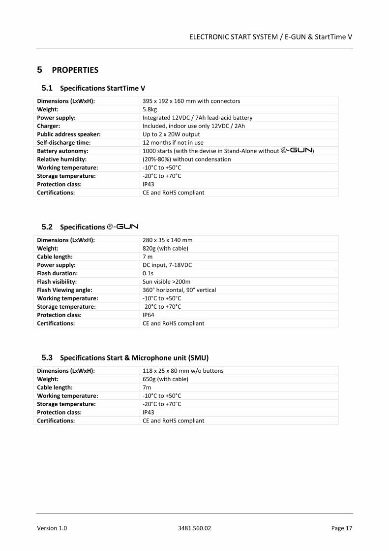
5 PROPERTIES
5.1 Specifications StartTime V
Dimensions (LxWxH): 395 x 192 x 160 mm with connectors
Weight: 5.8kg
Power supply: Integrated 12VDC / 7Ah lead-acid battery
Charger: Included, indoor use only 12VDC / 2Ah
Public address speaker: Up to 2 x 20W output
Self-discharge time: 12 months if not in use
Battery autonomy: 1000 starts (with the devise in Stand-Alone without )
Relative humidity: (20%-80%) without condensation
Working temperature: -10°C to +50°C
Storage temperature: -20°C to +70°C
Protection class: IP43
Certifications: CE and RoHS compliant
5.2 Specifications
Dimensions (LxWxH): 280 x 35 x 140 mm
Weight: 820g (with cable)
Cable length: 7 m
Power supply: DC input, 7-18VDC
Flash duration: 0.1s
Flash visibility: Sun visible >200m
Flash Viewing angle: 360° horizontal, 90° vertical
Working temperature: -10°C to +50°C
Storage temperature: -20°C to +70°C
Protection class: IP64
Certifications: CE and RoHS compliant
5.3 Specifications Start & Microphone unit (SMU)
Dimensions (LxWxH): 118 x 25 x 80 mm w/o buttons
Weight: 650g (with cable)
Cable length: 7m
Working temperature: -10°C to +50°C
Storage temperature: -20°C to +70°C
Protection class: IP43
Certifications: CE and RoHS compliant
Page 18 3481.560.02 Version 1.0
6 OPTIONS
6.1 Auxiliary flash
Optical signalling device for the start connected directly to the StartTime V, it can be positioned to one's liking near the deaf athlete.
3481.951.25 OMEGA FLASH Start
6.2 External loudspeaker
External loudspeaker for the start connected directly to the StartTime V, it can be positioned to one's liking near the athletes for better sound.
3399.933.06 Set of 3 mobile loudspeakers with 6m cables
3399.940.03 Set of 10 mobile loudspeakers with 3m cables
3399.938.03 Set of 8 mobile loudspeakers with 3m cables
3399.936.03 Set of 6 mobile loudspeakers with 3m cables
3399.935.06 Set of 5 mobile loudspeakers with 6m cables
3399.935.03 Set of 5 mobile loudspeakers with 3m cables
3399.934.06 Set of 4 mobile loudspeakers with 6m cables
3399.934.03 Set of 4 mobile loudspeakers with 3m cables
3399.930 Mobile loudspeakers with cable for deckplate (5m)
ELECTRONIC START SYSTEM / E-GUN & StartTime V
Version 1.0 3481.560.02 Page 19
7 MAINTENANCE AND PROTECTION
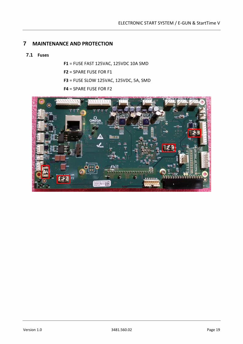
7.1 Fuses
F1 = FUSE FAST 125VAC, 125VDC 10A SMD
F2 = SPARE FUSE FOR F1
F3 = FUSE SLOW 125VAC, 125VDC, 5A, SMD
F4 = SPARE FUSE FOR F2
F2 F3
Page 20 3481.560.02 Version 1.0
8 APPENDIX
8.1 Abbreviations and symbols
Abbreviations
STV StartTime V
SMU Start & Microphone unit
CUS Custom
AT Athletics
AQ Aquatics
SS Speed Skating
SW Swimming
TIMER Quantum, ARES
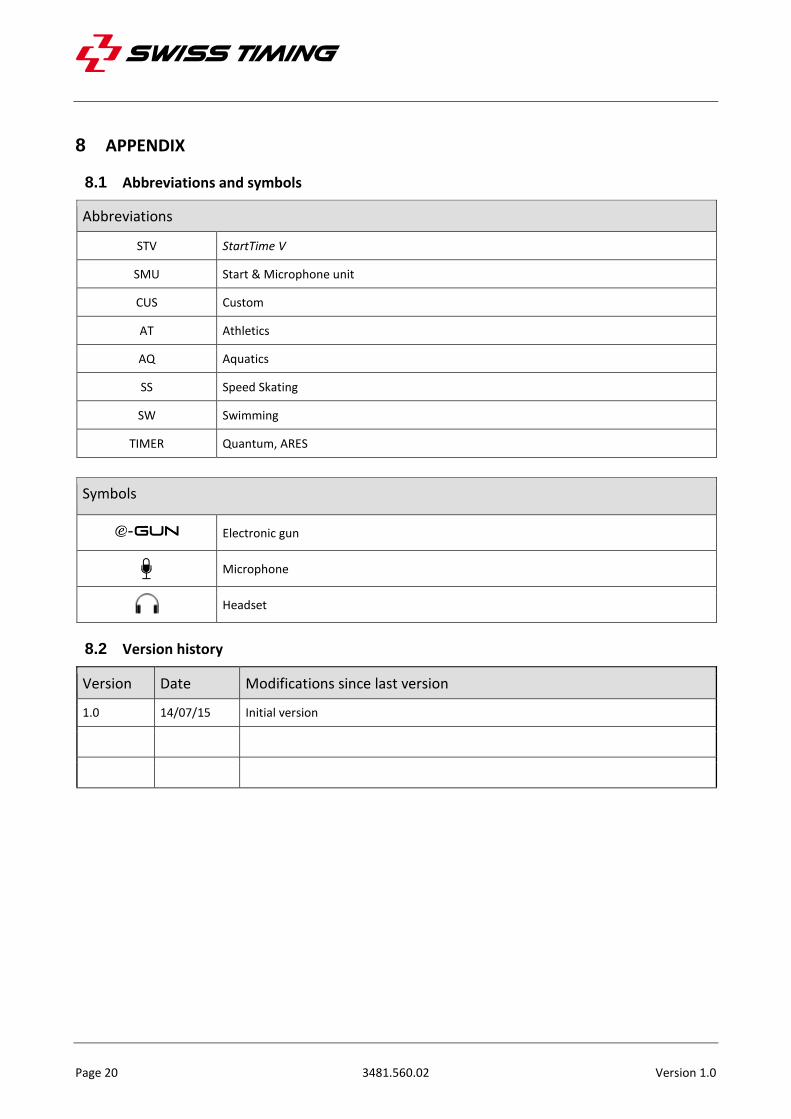
Symbols
Electronic gun
Microphone
Headset
8.2 Version history
Version Date Modifications since last version
1.0 14/07/15 Initial version
ELECTRONIC START SYSTEM / E-GUN & StartTime V
Version 1.0 3481.560.02 Page 21
NOTES


Swiss Timing LTD Phone +41 32 488 36 11 P.O. Box 138, Rue de l’Envers 1 [email protected] CH-2606 Corgémont - Switzerland www.swisstiming.com