Embed Size (px)
Citation preview

Page 1 E-FRM-9800 REV G
Met One Instruments, Inc. 1600 NW Washington Blvd.
Grants Pass, OR 97526 Telephone: (541) 471-7111 Facsimile: (541) 471-7116
www.metone.com
E-FRM Particulate Sampler Operation Manual - © Copyright 2013 Met One Instruments, Inc. All Rights Reserved worldwide. No part of this publication may be reproduced, transmitted, transcribed, stored in a retrieval system, or translated
into any other language in any form without the express written permission of Met One Instruments, Inc.
E-FRM REFERENCE METHOD
PARTICULATE SAMPLER OPERATION MANUAL
DOCUMENT NUMBER: E-FRM-9800, REV G

Page 2 E-FRM-9800 REV G
Table of Contents 1 INTRODUCTION 3
1.1 About This Manual ..................................................................................................... 3 1.2 Technical Service ....................................................................................................... 3 1.3 E-FRM: Environmental Federal Reference Method Sampler ..................................... 4 1.4 Reference Documents ............................................................................................... 5 1.5 Model E-FRM Specifications ...................................................................................... 6
2 SITE SELECTION and SETUP 7 2.1 Site Selection and Inlet Positioning Criteria ............................................................... 7 2.2 Electrical Service ........................................................................................................ 9 2.3 Instrument Assembly and Deployment Instructions ................................................. 10 2.4 Configuring The Unit for PM2.5 or Other Particulate Cut-Points ................................ 15
3 SCHEDULING SAMPLE EVENTS and SAMPLER OPERATION 16 3.1 The Main Menu and Using the Keypad and Display ................................................ 16 3.2 Setting Up New Sample Events Using the Event Manager ...................................... 17 3.3 Setting Event Defaults for Length and PM Type ...................................................... 19 3.4 Setting the Clock ...................................................................................................... 20 3.5 Setting the Unit ID .................................................................................................... 20 3.6 Clearing Event History and Data Files from Memory ............................................... 21 3.7 Viewing Current and Previous Sample Events ......................................................... 21
4 FLOW CONTROL SYSTEM AUDITS and CALIBRATIONS 23 4.1 Flow System Diagram .............................................................................................. 23 4.2 Quick Temperature, Pressure, & Flow Checks Using System Test ......................... 24 4.3 Leak Check and Flow Audit Intervals ....................................................................... 24 4.4 Leak Check Procedures and Leak Troubleshooting ................................................. 25 4.5 Ambient and Filter Temperature Audits and Calibrations ......................................... 26 4.6 Barometric Pressure Audits and Calibrations ........................................................... 27 4.7 Flow Audits and Multi-Point Calibration .................................................................... 28
5 MAINTENANCE and TROUBLESHOOTING 29 5.1 Met One Recommended Periodic Maintenance Table ............................................. 29 5.2 Sampler Error and Alarm Descriptions ..................................................................... 29 5.3 Basic Problem and Cause/Solution Table ................................................................ 30
6 DATA RETRIEVAL 31 6.1 Using the RS-232 or USB Cable Connections ......................................................... 31 6.2 Using a USB Flash Drive ......................................................................................... 31
7 SERIAL COMMUNICATIONS 32 7.1 User Communication ................................................................................................ 32 7.2 Computer Communication ....................................................................................... 33
8 ACCESSORIES and PARTS 34 8.1 Consumables, Replacement Parts, and Accessories ............................................... 34

E-FRM-9800 REV G Page 3
1 INTRODUCTION
1.1 About This Manual This document is organized with the most important information toward the front of the manual. All users should read and understand the sections on setup, operation, and field audits. Toward the back are sections that provide in-depth information on subjects such as diagnostics and accessories. These sections should be consulted as needed. This manual is periodically revised for maximum accuracy and to incorporate new features or updates. User feedback is welcome. Electronic versions of this manual are available upon request.
1.2 Technical Service Should you still require support after consulting your printed documentation, we encourage you to contact one of our expert Technical Service representatives during normal business hours of 7:00 a.m. to 4:00 p.m. Pacific Standard Time, Monday through Friday. In addition, technical information and service bulletins are often posted on our website. Please contact us and obtain a Return Authorization (RA) number before sending any equipment back to the factory. This allows us to track and schedule service work and to expedite customer service. Contact Information:
Tel: + 541 471 7111 Fax: + 541 471 7115 Web: http:/www.metone.com Email: [email protected]
Address: Met One Instruments, Inc.1600 Washington Blvd Grants Pass, Oregon 97526 U.S.A.
Please have your instrument serial number available when contacting the manufacturer. On most models manufactured by Met One Instruments, it will be located on a silver product label on the unit, and also printed on the calibration certificate. The serial number will begin with a letter and be followed by a unique four or five digit number such as F8029 or M20584.

Page 4 E-FRM-9800 REV G
1.3 E-FRM: Environmental Federal Reference Method Sampler The Met One Instruments, Inc. Model E-FRM is a programmable single-event filter sampler designed to meet federal specifications as a reference method for the determination of daily PM2.5 or PM10 particulate concentrations in ambient air. It employs a single pre-weighed 47 mm sample filter disc in an EPA-standardized cassette which must be manually exchanged by the operator prior to each sample period. The instrument runs a sample period based on an operator programmed start time and sample duration. A vacuum pump, controlled to 16.67 liters-per-minute, draws ambient air through a series of standardized inlets that provide the PM2.5 or PM10 cut points. The sample then passes through the filter, where the airborne particulate matter is deposited. The dirty filter is collected after the sample period and sent to a lab to be equilibrated and reweighed per the standardized EPA gravimetric procedures. The resulting clean and dirty mass values for the filter are then correlated to the volume of air sampled to determine the concentration of particulate in micrograms-per-cubic-meter (µg/m3) The E-FRM can easily be configured for reference method PM2.5 sampling using the standardized BGI VSCC™ very-sharp-cut cyclone, the URG-2000-30EGN cyclone, or the classic WINS Impactor. Alternately, other sharp-cut cyclones can be installed for non-designated or indicative PM2.5 or PM1 sampling. If PM10 monitoring is desired, the PM2.5 cyclones can be omitted entirely and a pass-through adapter can be installed in its place.
1.3.1 Model E-FRM PM10 U.S. EPA Federal Reference Method Designation Number RFPS-0216-231, “Met One Instruments, Inc. E-FRM,” configured for filter sampling of ambient particulate matter using the US EPA PM10 inlet specified in 40 CFR part 50 appendix L, Figs. L-2 thru L-19, with a flow rate of 16.67 L/min, using 47 mm PTFE membrane filter media, and operating with firmware version R2.0.1 and later, and operated in accordance with the Met One E-FRM PM10 operating manual. This designation applies to PM10 measurements only.
1.3.2 PM2.5 U.S. EPA Federal Reference Methods
BGI Very Sharp Cut Cyclone (VSCC) or WINS Impactor Designation Number RFPS-0315-221, “Met One Instruments, Inc. E-FRM,” configured for filter sampling of ambient particles using the US EPA PM10 inlet specified in 40 CFR 50 Appendix L, Figs. L-2 thru L-19, equipped with either a BGI VSCC™ cyclone or WINS PM2.5 fractionator, with a flow rate of 16.67L/min, using 47 mm PTFE membrane filter media, and operating with firmware version R1.1.0 and later, and operated in accordance with the Met One E-FRM PM2.5 operating manual.
URG-2000-30 EGN Cyclone Designation Number EQPS-0316-235, “Met One Instruments, Inc. E-FRM,” configured for filter sampling of ambient particulate matter using the US EPA PM10 inlet specified in 40 CFR 50 Appendix L, Figs. L-2 thru L-19, equipped with a URG-2000-30EGN Cyclone particle size

E-FRM-9800 REV G Page 5
separator, and operated for a continuous 24-hour sample period at a flow rate of 16.67 liters/minute, using 47 mm PTFE membrane filter media, and operating with firmware version R1.1.0 and later, and operated in accordance with the Met One E-FRM PM2.5 operating manual.
1.3.3 Model E-FRM Coarse U.S. EPA Federal Reference Method Designation Number RFPS-0316-232, “Met One Instruments, Inc. E-FRM-PM10 and E-FRM-PM2.5 Sampler Pair” for the determination of coarse particulate matter as PM10-2.5, consisting of a pair of Met One Instruments, Inc. E-FRM samplers, with one being the E-FRM PM2.5 sampler (RFPS-0315-221) and the other being the E-FRM PM10 sampler (RFPS-0216-231). The units are to be collocated to within 1-4 meters of one another and sample concurrently. Both units are operated in accordance with the associated E-FRM instruction manual. This designation applies to PM10-2.5 measurements only.
1.4 Reference Documents The following documents provide additional or related information on the regulations, methods, and standard operating procedures for reference method samplers:
• Quality Assurance Guidance Document 2.12. Monitoring PM2.5 in Ambient Air Using Designated Reference or Class I Equivalent Methods. U.S. EPA, National Exposure Research Laboratory. Research Triangle Park, NC, May 1998 or later.
• Title 40 Code of Federal Regulations (40 CFR), Part 50, Appendix L. REFERENCE METHOD FOR THE DETERMINATION OF FINE PARTICULATE MATTER AS PM2.5 IN THE ATMOSPHERE.

Page 6 E-FRM-9800 REV G
1.5 Model E-FRM Specifications PARAMETER SPECIFICATION
Measurement Principle: Programmable single-event filter sampler for ambient PM2.5 particulate concentrations by gravimetric laboratory analysis.
Resulting Data Units: Micrograms per actual cubic meter µg/m3 . Calculated from lab filter weights. Design Specifications: Title 40 CFR, Part 50 Appendix L.
U.S. EPA Designations: Federal Reference Methods RFPS-0315-221, RFPS-0216-231, RFPS-0316-232, and EQPS-0316-235 (see section 1.3)
Main Inlet Type: EPA-pattern PM10 size-selective louvered inlet standard (Met One BX-802). PM2.5 Separator Type: BGI VSCC-A™ Cyclone or URG-2000-30EGN Cyclone (WINS Impactor optional) PM10 Sampling Config: Pass-through tube (used in place of cyclone) included for PM10 sampling. Other Configurations: Compatible with PM2.5 or PM1 SCC cyclones. TSP inlet available. Filter Type: 47mm PTFE disc filters standard. Other filter material types available. Filter Holder: Accommodates standard EPA-pattern white Delrin filter cassettes. Filter Temp Control: Within 5 degrees C of ambient, sampling and standby. Logged in data. Operating Temperature: -30 to +50 degrees C, Ambient. Operating Pressure: 600 to 800 mmHg, Ambient. Sample Events: 24 hour samples standard. Programmable start date/time and duration. Flow Rate: 16.67 L/min (1 m3/hr). With flow sensor and real-time actual flow control. Flow Accuracy: ±2% (±.33 L/min). Flow Records: Flow rate, temperature, pressure logged in 5 minute intervals. Vacuum Pump: Dual-head diaphragm AC pump standard (specify voltage). Upper Conc Limit: At least 200 µg/m3 estimated for daily average.* Data Collection: 9-Pin RS-232 port. USB data port. USB flash drive port. Software supplied. Memory Capacity: 24 sample events Compatible Software: FRM Comm Aq User Interface: Extended temperature 8x40 character LCD display with dynamic keypad. Enclosure Type: Active fan ventilation with solar shield and separate pump enclosure. Deployed Dimensions: 2.0 meters (77”) high, 42 cm (16.5”) wide, 53 cm (20.75”) deep. Stowed Dimensions: 105 cm (41”) high, 42 cm (16.5”) wide, 53 cm (20.75”) deep. Weight: Complete System: 33 kg (73 lbs). Removable pump box: 12.7 kg (28 lbs). Power: 100 to 125VAC, 2.5 amps nominal, start up current will be greater * The approximate upper concentration limit is based on the samplers ability to maintain 16.67 L/min sample flow over the entire 24 hour period, despite PTFE filter loading with typical urban PM2.5 particulate. Actual concentration limits will vary depending on ambient conditions, altitude, and particulate type.
Specifications may be subject to change without notice.

E-FRM-9800 REV G Page 7
2 SITE SELECTION and SETUP Use the following information to correctly assemble, configure, and deploy the E-FRM sampler. Installation of the sampler should ideally be performed by personnel familiar with environmental monitoring equipment. There are no special precautions or handling concerns except for the normal level of care required for handling scientific equipment. Refer to the instructions and diagrams on the following pages. When unpacking a new instrument, verify that the contents are undamaged. If the shipping cartons are damaged, notify the carrier immediately. Verify that the included accessories are correct and complete. If anything is missing, contact the technical service department at [email protected] or (541) 471-7111. See the Accessories section at the back of this manual for more details. The normal configuration of the instrument is supplied with the following standard accessories:
• Main weatherproof instrument enclosure with quick deployment aluminum stand • Removable pump box module with built-in power supply and flow monitoring/control. • BX-802 EPA Pattern PM10 inlet. • Pass-through adapter for PM10 sampling. • One 47 mm filter cassette assembly. • PTFE sample filters. • Leak test valve. • Inlet tube. • Ambient temperature sensor with solar gill shield. • FRM Comm data acquisition software. • Serial communications cable. • Instruction manual.
The following optional accessories may or may not also be included, depending on the order:
• Non-reference cyclones for PM2.5 or PM1 cut-points. • BX-808 BGI VSCC™ PM2.5 cyclone. • BX-809 URG-2000-30EGN PM2.5 cyclone. • Extra 47 mm filter holders or filters.
2.1 Site Selection and Inlet Positioning Criteria Selection of a proper site for the sampler is critical for accurate measurements. These items must be correctly addressed in order for the collected data to be acceptable for regulatory requirements, such as EPA PM10 or PM2.5 data reporting. Specifications for site selection and inlet positioning for FRM samplers can be found in United States regulation 40 CFR, Part 58, Appendix D and E. There are also a variety of EPA guidance documents and quality assurance documents which describe site criteria in detail. In any case, the Code of Federal Regulations takes precedence. Site selection and inlet position criteria may vary in other countries. Note: The sampler location may consist of an elevated site such as a flat rooftop, the top of a walk-in lab shelter, or an elevated platform. The location may also be at or near ground level on a concrete pad or a simple wooden platform. In any case, the location must be level and easily accessible for routine service and filter replacement. Locating the sampler stand directly on the soil is not usually recommended, due to possible intrusion of dirt, insects, and vegetative growth.

Page 8 E-FRM-9800 REV G
Inlet Height Criteria:
• The sampler total inlet height must be located in the “breathing zone”, between 2 and 15 meters above ground level for neighborhood scale sites. Middle scale or microscale sites require a total inlet height of between 2 and 7 meters.
• If the unit is to be installed on ground level, then the inlet height must be at least two meters above the ground. The sampler stand and enclosure are designed to locate the inlet two meters above whatever surface the unit is placed on.
• If the unit is located on the roof of a building, the inlet height must be no less than two meters above roof surface of the building. The total height must be no more than 15 meters above ground level.
• If the sampler is to be collocated with other particulate instruments, such as BAM units or other samplers or monitors, then the air inlets must all be the same height within one meter vertically. Met One recommends a tighter tolerance of within 30cm (1 foot).
• If the sampler inlet is the highest metallic point on a building, then a lightning rod must be installed to prevent destruction of the sampler during electrical storms.
Inlet Spacing and Clearance Criteria:
• If the sampler is to be collocated with another instrument, such as a BAM-1020 or other sampler or monitor, then the inlets must be spaced between one and four meters apart. Two meter spacing is recommended where possible.
• If installed near a PM10 high-volume sampler, then the distance between the inlet of the sampler and the Hi-Vol should be no less than three meters.
• The sampler inlet must be unobstructed for two meters in all directions from any object that may influence airflow characteristics, such as walls, parapets, or structures on a rooftop.
• If located beside a major obstruction (such as a building), then the distance between the inlet and the building should be equal to twice the height of the building.
• There must be at least a 180 degree arc of completely unrestricted airflow around the sampler inlet. The predominant wind direction during the highest concentration season must be included in the 180 degree arc.
• The sampler inlet must be at least 10 meters from the drip line of any trees. Artificial Particulate Sources: To avoid possible errors in the concentration measurements, the inlet must be located as far as possible from any artificial sources of particulate, such as blowers or vents on a rooftop. Even sources of filtered air must not blow across the sampler inlet. Spacing from Roadways: Except for microscale studies or purposeful near-road studies, the sampler should usually not be located directly next to a major highway or arterial roadway, as vehicle exhaust will

E-FRM-9800 REV G Page 9
dominate the concentration measurement. Criteria for roadway spacing of particulate monitors can be complicated. See 40 CFR Part 58 - Appendix E, section 6.3 (July 2009).
• For general neighborhood scale monitoring, the sampler should be at least 10 meters away from a road with a daily traffic volume of less than 1,000 vehicles, at least 30 meters from a road with a volume of 20,000 vehicles, at least 100 meters from a road with a volume of 70,000 vehicles, and at least 250 meters from a road with a volume of greater than 110,000 vehicles.
• The unit should be located as far as possible from unpaved roadways, as these also cause artificial measurements from temporarily suspended fugitive dust.
• The unit should usually not be installed in unpaved areas unless year-round vegetative ground cover is present, to avoid the effects of re-entrained fugitive dust.
2.2 Electrical Service The standard version of the E-FRM sampler is either 120V or 230V AC powered, depending on which vacuum pump is ordered. A standard U.S.A. type power cord is supplied with all 120V units, and a European Schuko type cord is supplied with all 230V units. Special cording may be available upon request. The sample site needs to be equipped with AC power and a standard weatherproof outdoor electrical outlet. The sampler is rated at 2.5 amps max continuous with the pump running. Pump start-up inrush current is higher. An earth-ground point near the unit is recommended. For critical applications where possible sample invalidations due to power failures are unacceptable, the sampler should be equipped with a backup uninterruptable power supply (UPS). The supply must be rated for the electrical load, and must be appropriately configured for an outdoor application. Consult a qualified electrical contractor.

Page 10 E-FRM-9800 REV G
2.3 Instrument Assembly and Deployment Instructions The E-FRM sampler is designed for easy setup and deployment. This allows it to be used for either permanent long-term sampling at a fixed site, or for portable audit sampling.
1. Deploy the Upper Filter Enclosure: The sampler should be shipped and stored in the stowed configuration shown in Figure 2-1.
a. Remove the two wing screws (one on each side) that hold the upper enclosure in the stowed position in the stand.
b. Locate the handle mounted on the top of the upper enclosure. Note that when the upper enclosure is in the stowed position, this handle will be on the bottom.
c. Grasp the handle and rotate the enclosure forward into the vertical position as shown in Figure 2-2.
d. Fasten the upper enclosure in the deployed position by installing the two wing screws into the deployed hole positions in the stand.
Note: It is not necessary to remove or loosen the two pivot screws that hold the upper enclosure and the stand together.
Figure 2-1 Stowed Orientation
Figure 2-2 Deployed Orientation
Wing Screws
Pivot Screws
Deployed Hole Position

E-FRM-9800 REV G Page 11
2. Install the Pump Box Module: The pump box is stowed in the bottom of the stand and must be mounted to the bottom of the upper enclosure for operations.
a. Open the door of the upper enclosure for better visibility. Remove the two wing nuts that retain the pump box module in the base of the stand and the one wing nut in the spacer on top of the pump box.
b. Lift the pump box out of the stand and slide it onto the rails on the bottom of the upper enclosure, as shown in Figure 2-3. Slide the pump box all the way back until it stops.
c. Install the wing screw through the floor of the upper enclosure and into the spacer on top of the pump box. This is a security feature to prevent the pump box from vibrating out of position or from being removed without access to the inside of the main enclosure.
d. Uncoil the power cord, pump box signal cord, and vacuum tube from the bottom of the pump box.
e. Connect the vacuum tube and pump box cord to the back of the upper enclosure as shown in Figure 2-4.
Figure 2-3 Pump Box Deploys by Sliding
in to Rails Shown Here
Figure 2-4 Cord and Tubing Connections
Pump Box Cord Vacuum Tube
Temperature Sensor Cord

Page 12 E-FRM-9800 REV G
3. Install the Temperature Sensor and External Inlets:
a. Install the ambient temperature sensor to the upper enclosure as shown in Figure 2-5.
Figure 2-5 Fully Deployed E-FRM Monitor
b. Connect the temperature sensor cable to the back of the upper enclosure (see Figure 2-4).
c. Loosen the black plastic fitting on the top of the inlet tube receiver.
d. Install the vertical inlet tube into the top of the enclosure. The long end of the tube goes down. Make sure the tube snaps into the o-ring socket securely, then tighten the black plastic fitting.
e. Install the BX-802 PM10 inlet on top of the inlet tube.
Note: The PM10 inlet is used in all configurations of the E-FRM sampler. It serves as a pre-separator for subsequent PM2.5 stages when using either the BX-808 or BX-809 cyclonic separators.
Temperature Sensor
BX-802 PM10 Inlet
Inlet Tube

E-FRM-9800 REV G Page 13
4. Configure the PM2.5 Cyclone and Filter Holder: The PM2.5 cyclone and filter cassette are mounted inside the upper enclosure. Skip to the next section if the sampler is being used to collect PM10 particulate.
a. The sampler is usually supplied with either a VSCC or URG-2000-30EGN PM2.5
cyclone which should already be installed inside the upper enclosure as shown in Figure 2-6. If it has been removed, it should be installed now by inserting it into the socket in the roof of the sampler.
b. The upper filter holder mounts into the bottom of the cyclone. c. A white filter cassette is clamped into the bottom of the upper filter holder with
the filter clamp assembly. The clamp assembly is supplied with a detent pin installed in the left side of the filter release handle which prevents it from falling open during shipment. Remove the pin to allow the clamp assembly to be opened by pulling the handle forward. This allows access to the filter cassette.
Note: The standard PM2.5 cyclone may be exchanged for a WINS Impactor or PM10 pass-through adapter. In the case of either PM2.5 adapter, the upper filter holder must be used.
Figure 2-6 PM2.5 Configuration
PM2.5 Cyclone
Filter Cassette
Upper Filter Holder
Filter Release Handle

Page 14 E-FRM-9800 REV G
5. Configure the PM10 Adapter and Filter Holder: The PM10 pass-through adapter and filter cassette are mounted inside the upper enclosure. If monitoring PM2.5, follow the instructions in the previous step instead of this one.
a. Remove the PM2.5 cyclone or impactor and the upper filter holder if they are installed.
b. Insert the PM10 pass-through adapter into the socket in the roof of the sampler as shown in Figure 2-7
c. A white filter cassette is clamped into the bottom of the adapter with the filter clamp assembly. The clamp assembly is supplied with a detent pin installed in the left side of the filter release handle which prevents it from falling open during shipment. Remove the pin to allow the clamp assembly to be opened by pulling the handle forward. This allows access to the filter cassette.
Note: The adapter includes the functionality of the upper filter holder in its design so it is not necessary to install it when using the PM10 pass-through adapter.
Figure 2-7 PM10 Configuration
6. Fasten Down the Stand: For long-term deployments, the E-FRM sampler stand must be fastened down to the mounting surface in order to prevent wind-toppling, theft, or unauthorized repositioning. This is especially critical if the sampler is located on a platform, rooftop, or other elevated surface. The holes in the base may be utilized to accommodate lag bolts or anchor bolts.
PM10 pass-through adapter in place of cyclone
Filter Release Handle
E-FRM-9800 REV G Page 15
2.4 Configuring The Unit for PM2.5 or Other Particulate Cut-Points It is critical for the user to understand and keep track of the exact inlet hardware configuration, in order to ensure that the resulting concentration data is identified for the correct PM classification! The sampler cannot automatically identify the inlet cut-point configuration. The inlet configuration type should be selected to match the physical setup hardware by the operator through the user interface. This setting will appear in the data files for quality assurance purposes. See Section 3 All standard configurations of the sampler use a standard louvered PM10 size-selective inlet (Met One BX-802) as the main air inlet for the system. This inlet separates out and traps water, debris, and particles larger than 10 microns in size, while allowing smaller particles through to the sampler. For PM2.5 sampling, the PM10 inlet serves as a particulate pre-separator for the secondary cyclone or impactor stage inside the sampler. For PM10 sampling, a pass-through adapter (Met One Instruments part number 81210) is installed in place of a PM2.5 separator to allow the particulate directly through to the filter. The sampler is configured for PM2.5 sampling by using an internal VSCC™ (Very-Sharp-Cut Cyclone, Met One Instruments part number BX-808) or URG-2000-30EGN cyclonic separator (Met One Instruments part number BX-809) to further separate out and trap particles larger than 2.5 microns in size, while allowing smaller particles through to the sample filter. The particle performance of these cyclones closely match that of the classic WINS Impactor, but with simpler maintenance requirements. All VSCC™ cyclones are manufactured by BGI, Inc. and all URG-2000-30EGN cyclonic separators are manufactured by URG, Corp. as a condition of the EPA designated status of the cyclones. See www.bgiusa.com and www.urgcorp.com for details. The classic WINS Impactor, built to 40 CFR Part 50L specifications, is the predecessor to the cyclone BGI and URG cyclones for designated PM2.5 sampling, and is available from Met One Instruments (part number BX-804) upon request. It fits into the same position as the BX-808 and BX-809 inside the sampler. The cyclone position can accommodate an older style SCC (Sharp-Cut-Cyclone, Met One Instruments part number BX-807) for less common PM2.5 sampling applications where a lower cost system is needed and EPA designation is not required for the resulting data. The SCC cyclone is very similar to the VSCC™ and the URG-2000-30EGN cyclone, but is not designated as a Federal Reference Method for PM2.5. The cyclone position can also accommodate a version of the SCC Sharp-Cut-Cyclone for PM1 sampling (Met One BX-811). This separates out particles larger than 1 micron in size. This configuration is not very common because PM1 sampling is not currently regulated or designated by the EPA.

Page 16 E-FRM-9800 REV G
3 SCHEDULING SAMPLE EVENTS and SAMPLER OPERATION This section describes the process for setting up and running scheduled sample periods using the Event and Setup menus in the E-FRM sampler user interface.
3.1 The Main Menu and Using the Keypad and Display When the E-FRM sampler is powered up it will display the main top level menu on the LCD display as shown in Figure 3-1. This menu is the starting point for all functions of the sampler.
Figure 3-1 The E-FRM sampler User Interface and Keypad
Soft Keys: Beneath the display are four white “soft-keys”. The function of these buttons change based on menu options displayed above them on the bottom row of the display. Arrows: The four white arrow keys are used to scroll up, down, left, and right, and to move the cursor to select an editable field on the screen. The arrow keys are also often used to increment or decrement values within a selected parameter on the screen. Contrast Button: The sun-shaped button is the LCD contrast adjustment. Press and hold the button until the desired contrast is achieved. The screen contrast will cycle from full to none for as long as this button is pressed. Note that is possible to adjust the contrast so that the entire screen looks blank and the unit appears to be off or nonfunctional when it is not.
Filter Sampler E-FRMx-01 R0.90.5
Met One Instruments, Inc.
www.metone.com Transfer
Event Setup Calibrate Data
F1 F2 F3
F4 F5 F6
Soft Keys
E-FRM-9800 REV G Page 17
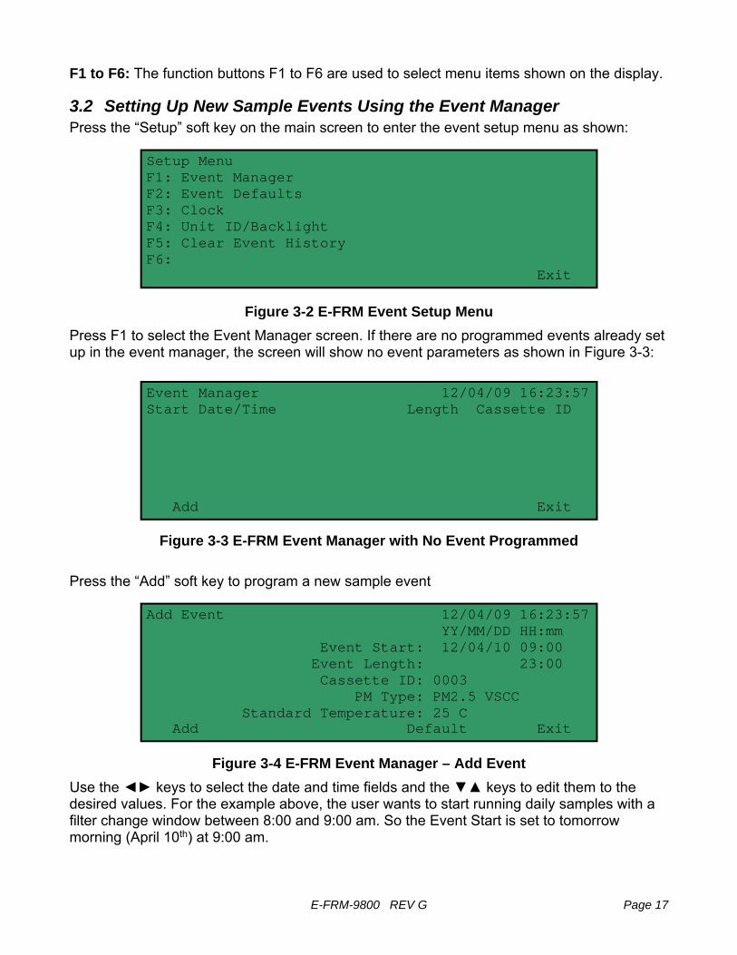
F1 to F6: The function buttons F1 to F6 are used to select menu items shown on the display.
3.2 Setting Up New Sample Events Using the Event Manager Press the “Setup” soft key on the main screen to enter the event setup menu as shown:
Figure 3-2 E-FRM Event Setup Menu
Press F1 to select the Event Manager screen. If there are no programmed events already set up in the event manager, the screen will show no event parameters as shown in Figure 3-3:
Figure 3-3 E-FRM Event Manager with No Event Programmed
Press the “Add” soft key to program a new sample event
Figure 3-4 E-FRM Event Manager – Add Event
Use the ◄► keys to select the date and time fields and the ▼▲ keys to edit them to the desired values. For the example above, the user wants to start running daily samples with a filter change window between 8:00 and 9:00 am. So the Event Start is set to tomorrow morning (April 10th) at 9:00 am.
Setup Menu F1: Event Manager F2: Event Defaults F3: Clock F4: Unit ID/Backlight F5: Clear Event History F6:
Exit
Event Manager 12/04/09 16:23:57 Start Date/Time Length Cassette ID Add Exit
Add Event 12/04/09 16:23:57 YY/MM/DD HH:mm Event Start: 12/04/10 09:00 Event Length: 23:00 Cassette ID: 0003 PM Type: PM2.5 VSCC
Standard Temperature: 25 C Add Default Exit

Page 18 E-FRM-9800 REV G
The “Event Length” parameter will default to the value specified in the “Event Defaults” menu, and will almost always be set to either 23 or 24 hours. Use the ◄► keys to select the field and the ▼▲ keys to edit the value if needed. For the example above, the user wants to run daily samples, so the Event Length is set to 23 hours to allow one hour for filter changes before the next sample is started. If the user wanted to run samples on a 1-in-3 or 1-in-6 day schedule, then he might set the Event Start value to midnight, and the Event Length value to 24 hours, since there is plenty of time between samples to collect and replace the filter. The “Cassette ID” parameter is used to enter the unique lab identification number of the sample filter, which will then appear in the sampler data files to allow the data to be correlated to the specific filter for quality assurance purposes. This value is usually assigned by the lab which pre-weighed the clean filter. The value can be set to any number between 0001 and 9999. Use the ◄► keys to select the field and the ▼▲ keys to edit the value if needed. The “PM Type” parameter is used to identify the physical inlet configuration of the sampler for quality assurances purposes, and will also appear in the sampler data files. It is up to the user to make sure that this value matches the actual physical configuration of the inlet parts. See Section 2.3. Once established initially, this value is rarely changed. The parameter can be set to the following values:
PM2.5 VSCC Internal BX-808 or BX-809 Cyclone installed (most common) PM2.5 SCC Internal PM2.5 Sharp-Cut Cyclone installed (uncommon) PM2.5 WINS Internal PM2.5 WINS Impactor installed.
PM10 Internal pass-through adapter installed, no cyclone or impactor used. PM1 SCC Internal PM1 Sharp-Cut Cyclone installed. (uncommon)
TSP Standard PM10 inlet replaced with TSP inlet. Internal pass-through adapter installed, no cyclone or impactor. (uncommon)
Table 3-1 E-FRM “PM Type” Options The “Standard Temperature” parameter is the value of Standard Temperature to be used when calculating the Standard Volume if required for reporting purposes. The value can be set as 0° C, 20° C, or 25° C. Use the ◄► keys to select the field and the ▼▲ keys to edit the value if needed.

E-FRM-9800 REV G Page 19
After all of the event parameters are set to the desired values, press the “Add” soft key under the display. The menu will exit out to the Event Manager screen, where the new event should appear in the list as shown below. The event can be modified or deleted using the soft keys at the bottom of the screen. Up to four programmed events can be scheduled.
Figure 3-5 E-FRM Event Manager with Programmed Event
3.3 Setting Event Defaults for Length and PM Type From the Setup menu, press the F2 button to enter the Event Defaults menu as shown in Figure 3-6.
Figure 3-6 E-FRM Event Defaults Menu
The “Event Length” parameter is the default sample time for new events, and will appear whenever a new event is created as in Section 3.2 above. However, the value can be edited easily in the event setup screen regardless of what this default value is set to. The default can be set to any value from 00:00 to 25:00, but will usually be set to either 23:00 for daily sampling, or 24:00 for 1-in-3 or 1-in-6 day sampling schedules. The “PM Type” parameter is the default value for the inlet configuration as described in Section 3.2 above. Once established initially, this parameter is rarely changed. The value can be edited easily in the event setup screen regardless of whatever this default value is programmed to be. The “Standard Temperature” parameter is the default value for the Standard Temperature to be used when calculating Standard Volume. The value can be set as 0° C, 20° C, or 25° C. Once set, this parameter is rarely changed. The value can be edited easily in the event setup screen regardless of whatever this default value is programmed to be. Press the Save soft key to save the values.
Event Manager 12/04/09 16:23:57 Start Date/Time Length Cassette ID 12/04/10 09:00:00 23:00 0003
Modify Delete Exit
Sample Event Defaults HH:mm Event Length: 24:00 PM Type: PM2.5 VSCC Standard Temperature: 25 C Save Exit

Page 20 E-FRM-9800 REV G
3.4 Setting the Clock From the Setup menu, press the F3 button to enter the “Clock” screen as shown in Figure 3-7.
Figure 3-7 E-FRM Clock Setup Screen
The current clock time of the system is shown in the upper right corner of the display. The correct date and time can be entered into the fields on the left side of the screen. Use the ◄► keys to select the desired field and use the ▼▲ keys to edit the value. Press the Set soft key to make the changes take effect and set the system clock. In most cases, it is recommended that the sampler clock be checked at least monthly, and maintained to within one minute of the actual time for accurate sample events.
3.5 Setting the Unit ID From the Setup menu, press the F4 button to enter the “Unit ID/Backlight” screen.
Figure 3-8 E-FRM Unit ID/Backlight Screen
The “Unit ID” parameter is used to establish a unique identification number for the sampler or sample site. This value will appear in the data files in order to correlate data to a certain site or sampler. The value can be set to the last four digits of the sampler serial number, or some other appropriate numeric value. This is not to be confused with the Cassette ID value which identifies the filter and changes for each sample period. The “Backlight” value is used to enable or disable the electroluminescent backlight for the LCD display whenever the unit is on. Most applications don’t require the backlight unless filter changes or sampler audits are performed after dark. The backlight has a limited lifetime of a couple of years during continuous use. Press the Save button when finished editing the values with the arrow buttons.
Clock Setup 12/04/09 16:23:57 YY/MM/DD Date: 12/04/09 HH:mm:ss Time: 16:20:00 Set Exit
Unit ID Unit ID: 0001 Backlight: OFF Save Exit

E-FRM-9800 REV G Page 21
3.6 Clearing Event History and Data Files from Memory From the Setup menu, press the F5 button to enter the “Clear Event History” screen. The screen will display a caution message. Press the Clear soft key to erase all logged data, archived events, and currently scheduled events from the sampler memory. Press the Cancel button to exit without erasing the memory. Warning: Clearing the memory will permanently remove all sampler data and clear all scheduled events!
3.7 Viewing Current and Previous Sample Events Press the “Event” soft key on the main screen to enter the event viewer menu as shown in Figure 3-9. This menu is used to view the status of current sampling events, and to review the details of previously run samples.
Figure 3-9 E-FRM Event Viewer Menu
Press the F1 button to enter the “Current Event Status” screen as shown in Figure 3-10.
Figure 3-10 E-FRM Current Event “Main Status” Screen
The main view (Figure 3-10) just shows the current sample timing and schedule. The << or >> soft keys below the display can be used to scroll through all available sampling parameters, in ten different view screens. The screens scroll through in a circular manner. The most important are accessed first using the >> soft key from the main view. The displayed parameter screens are summarized in Table 3-2.
Event Menu F1: Current Event Status F2: Previous Event Summary F3: F4: Event Manager F5: F6: Historical Event Summary
Exit
Status: Sampling 12/04/10 11:51:24 01 Cassette ID: 0001 PM Type: PM2.5 VSCC Event Start: 12/04/10 09:00:00 Event Stop: 12/04/11 08:00:00 Elapsed: 02:48:50 Remaining: 20:08:36 Stop << >> Exit
Page 22 E-FRM-9800 REV G
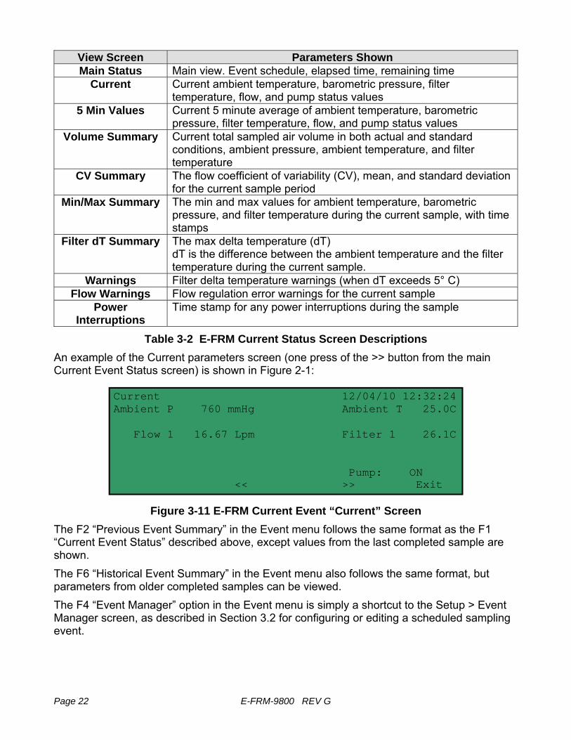
View Screen Parameters Shown Main Status Main view. Event schedule, elapsed time, remaining time
Current Current ambient temperature, barometric pressure, filter temperature, flow, and pump status values
5 Min Values Current 5 minute average of ambient temperature, barometric pressure, filter temperature, flow, and pump status values
Volume Summary Current total sampled air volume in both actual and standard conditions, ambient pressure, ambient temperature, and filter temperature
CV Summary The flow coefficient of variability (CV), mean, and standard deviation for the current sample period
Min/Max Summary The min and max values for ambient temperature, barometric pressure, and filter temperature during the current sample, with time stamps
Filter dT Summary The max delta temperature (dT) dT is the difference between the ambient temperature and the filter temperature during the current sample.
Warnings Filter delta temperature warnings (when dT exceeds 5° C) Flow Warnings Flow regulation error warnings for the current sample
Power Interruptions
Time stamp for any power interruptions during the sample
Table 3-2 E-FRM Current Status Screen Descriptions An example of the Current parameters screen (one press of the >> button from the main Current Event Status screen) is shown in Figure 2-1:
Figure 3-11 E-FRM Current Event “Current” Screen
The F2 “Previous Event Summary” in the Event menu follows the same format as the F1 “Current Event Status” described above, except values from the last completed sample are shown. The F6 “Historical Event Summary” in the Event menu also follows the same format, but parameters from older completed samples can be viewed. The F4 “Event Manager” option in the Event menu is simply a shortcut to the Setup > Event Manager screen, as described in Section 3.2 for configuring or editing a scheduled sampling event.
Current 12/04/10 12:32:24 Ambient P 760 mmHg Ambient T 25.0C Flow 1 16.67 Lpm Filter 1 26.1C
Pump: ON << >> Exit

E-FRM-9800 REV G Page 23
4 FLOW CONTROL SYSTEM AUDITS and CALIBRATIONS
4.1 Flow System Diagram The E-FRM sampler airflow control system is simple and effective, consisting of a few rugged components in a series configuration. Proper operation of the flow system is critical in order to obtain accurate volumetric concentration data from gravimetric filter analysis. The PM10 inlet and PM2.5 cyclones/impactors are designed to use the inertia of the particles as they flow through the inlet in order to trap particles above a certain size or “cut-point”. If the system airflow is too high or too low, then particles of the wrong size may be improperly included or excluded in error. Periodic leak checks and airflow audits must be performed to ensure the flow rate remains within specifications. The EPA-specified flow accuracy is ±5% (±0.83 L/min) of the 16.67 L/min design value for 5 minute flow averages. However, the E-FRM sampler is designed to maintain the flow with an accuracy of better than ±2% (0.33 L/min).
Figure 4-1 E-FRM Sampler Flow Control System
Not to scale. Simplified for clarity.
Flow Controller
Purge Volume
Flow Sensor
Vacuum Pump
Bypass Solenoid
Sample Filter Cassette
Filter Temperature Sensor
Debris Filter
Filter Pressure Port
PUMP BOX
FILTER ENCLOSURE
Leak Isolation Valve

Page 24 E-FRM-9800 REV G
4.2 Quick Temperature, Pressure, & Flow Checks Using System Test The System Test screen can be used at almost any time to quickly check or audit the current sampler values for ambient temperature, barometric pressure, filter temperature, and flow. From the Calibrate menu, press F1 to enter the System Test screen a shown below:
Figure 4-2 E-FRM System Test Screen
The Ambient T and Ambient P values are the current ambient temperature and barometric pressure readings from the sampler. The Filter 1 value is the current output from the filter temperature sensor located below the filter cassette, which should be within 5C of ambient at all times. Flow 1 is the current airflow rate of the sampler.
4.3 Leak Check and Flow Audit Intervals The critical aspects of filter sampler flow system maintenance include routine leak checks and temperature, pressure, and flow audits. Agencies who routinely verify these aspects almost always obtain high-quality concentration data from the unit. In general, the sampler flow rate accuracy should be audited periodically, and the flow bias assessed at least quarterly and annually. These activities are usually separated into two levels. “Audits” usually consist of checking the leak, temperature, pressure, and flow values from the sampler at a single point (usually at ambient conditions) comparing these values to a traceable standard device, and simply recording the results with no adjustments. Because these audits are fairly quick, they are usually performed on a regular basis, such as monthly. “Calibrations” usually consist of comparing the sampler values to the traceable standard device at one or multiple points, and making calibration adjustments to the sampler as needed. Calibration may be required as the result of a problem found during an audit, or may simply occur at a fixed interval as a matter of standard operating procedures, such as quarterly. Calibrations must always be documented.
System Test 12/04/10 12:32:24 Ambient P 727 mmHg Ambient T 25.0 C Sample P 724.2 Flow 1 16.67 Lpm Filter 1 25.2 C Set Point 16.67 Lpm Pump: ON Pump Exit
E-FRM-9800 REV G Page 25
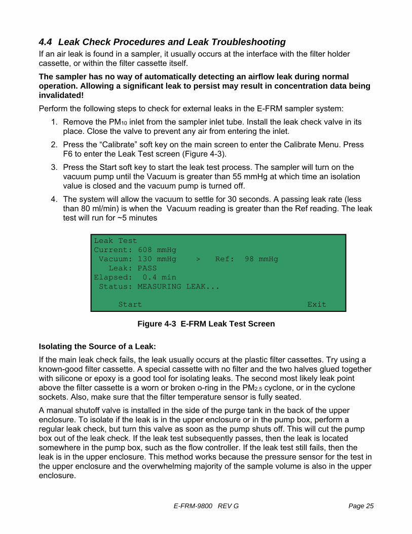
4.4 Leak Check Procedures and Leak Troubleshooting If an air leak is found in a sampler, it usually occurs at the interface with the filter holder cassette, or within the filter cassette itself. The sampler has no way of automatically detecting an airflow leak during normal operation. Allowing a significant leak to persist may result in concentration data being invalidated! Perform the following steps to check for external leaks in the E-FRM sampler system:
1. Remove the PM10 inlet from the sampler inlet tube. Install the leak check valve in its place. Close the valve to prevent any air from entering the inlet.
2. Press the “Calibrate” soft key on the main screen to enter the Calibrate Menu. Press F6 to enter the Leak Test screen (Figure 4-3).
3. Press the Start soft key to start the leak test process. The sampler will turn on the vacuum pump until the Vacuum is greater than 55 mmHg at which time an isolation value is closed and the vacuum pump is turned off.
4. The system will allow the vacuum to settle for 30 seconds. A passing leak rate (less than 80 ml/min) is when the Vacuum reading is greater than the Ref reading. The leak test will run for ~5 minutes
Figure 4-3 E-FRM Leak Test Screen
Isolating the Source of a Leak: If the main leak check fails, the leak usually occurs at the plastic filter cassettes. Try using a known-good filter cassette. A special cassette with no filter and the two halves glued together with silicone or epoxy is a good tool for isolating leaks. The second most likely leak point above the filter cassette is a worn or broken o-ring in the PM2.5 cyclone, or in the cyclone sockets. Also, make sure that the filter temperature sensor is fully seated. A manual shutoff valve is installed in the side of the purge tank in the back of the upper enclosure. To isolate if the leak is in the upper enclosure or in the pump box, perform a regular leak check, but turn this valve as soon as the pump shuts off. This will cut the pump box out of the leak check. If the leak test subsequently passes, then the leak is located somewhere in the pump box, such as the flow controller. If the leak test still fails, then the leak is in the upper enclosure. This method works because the pressure sensor for the test in the upper enclosure and the overwhelming majority of the sample volume is also in the upper enclosure.
Leak Test Current: 608 mmHg Vacuum: 130 mmHg > Ref: 98 mmHg Leak: PASS Elapsed: 0.4 min Status: MEASURING LEAK... Start Exit

Page 26 E-FRM-9800 REV G
Internal Filter Bypass Leakage Test: Per the FRM specifications in 40 CFR Part 50L, a secondary “internal filter bypass leakage” leak test must be performed to check for leaks below the filter cassette, even if the total external leak test passed. In theory, it should be impossible for this bypass leakage test to fail if the main external leakage test passed, but it is a useful test for isolating the source of a leak if the main test fails:
1. Configure a bypass leakage test cassette by installing a rubber membrane disc in a cassette in place of a standard filter disc. This will prevent any air from entering between the two halves of the cassette, and will also prevent any air from entering the system from any point above the cassette.
2. Install the special leak test cassette into the sampler and perform a leak test just as the main external leak test. The leak valve on the inlet tube is not needed.
3. The final bypass leak rate must be less than 80 ml/min just as in the main leak test.
4.5 Ambient and Filter Temperature Audits and Calibrations From the Calibrate menu, press F3 to enter the Temperature Calibration screen.
Figure 4-4 E-FRM Temperture Calibration Screen
There are two channels which can be audited using this screen, indicated in the top left corner. Channel (0) is the external ambient temperature sensor. Channel (1) is the internal filter temperature sensor located below the filter cassette. Use the ▲▼ keys to select the desired channel. The “Sensor” value is the output of the selected temperature sensor. To audit the ambient temperature sensor at a single point, place your traceable temperature standard probe near the sampler ambient temperature shield. Your probe should be of the type which is not affected by solar radiation. Compare the output of your probe with the “Sensor” value shown on the sampler screen. The two should match within 1.0 Deg C. Record the results. Each sensor can be calibrated at two points if needed. Point Pt1 is a low temperature point which is usually an ice bath if used, and Point Pt2 is a higher temperature point which is usually ambient, but could be a hot bath. The “Reference” column is where the correct temperature values from your traceable audit device can be entered into the screen for each point using the arrow keys. The “Save” column shows the currently entered calibration values associated with the Reference fields.
(0) Ambient Temperature Calibration Sensor Pt Save Reference 25.0 1 -30.0 -30.0 C Save(F1) 2 50.0 050.0 C Save(F4) Calibrate Default Exit

E-FRM-9800 REV G Page 27
Press the F1 button to save the low temperature “Reference” value that you entered into the “Save” field. Press the F4 button to save the high temperature “Reference” value that you entered into the “Save” field. After both values are entered, press the “Calibrate” soft key to implement the calibration. The “Default” button clears out all calibrations and restores factory calibration values. To audit or calibrate the filter temperature sensor, it is usually necessary to remove it from the sample line. You cannot assume that the filter sensor is at ambient conditions when installed, since it is specifically there to measure any difference between ambient and filter conditions.
4.6 Barometric Pressure Audits and Calibrations From the Calibrate menu, press F4 to enter the Pressure Calibration screen.
Figure 4-5 E-FRM Pressure Calibration Screen
The “Sensor” value is the output of the barometric pressure sensor. To audit the ambient barometric sensor at a single point, compare the output of your traceable pressure standard probe with the “Sensor” value shown on the sampler screen. The two should match within less than 10 mmHg. Record the results. Each sensor can be calibrated at two points if needed. Point Pt1 is a low pressure point, and Point Pt2 is a higher pressure point. The “Reference” column is where the correct pressure values from your traceable audit device can be entered into the screen for each point using the arrow keys. The “Save” column shows the currently entered calibration values associated with the Reference fields. Press the F1 button to save the low pressure “Reference” value that you entered into the “Save” field. Press the F4 button to save the high pressure “Reference” value that you entered into the “Save” field. After both values are entered, press the “Calibrate” soft key to implement the calibration. The “Default” button clears out all calibrations and restores factory calibration values.
Pressure Calibration Sensor Pt Save Reference 760 1 600 600 mmHg Save(F1) 2 800 800 mmHg Save(F4) Calibrate Default Exit
Page 28 E-FRM-9800 REV G
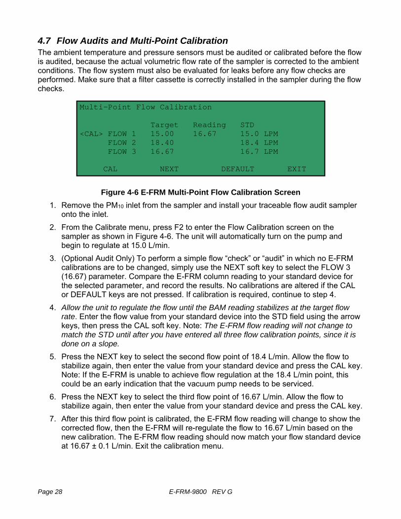
4.7 Flow Audits and Multi-Point Calibration The ambient temperature and pressure sensors must be audited or calibrated before the flow is audited, because the actual volumetric flow rate of the sampler is corrected to the ambient conditions. The flow system must also be evaluated for leaks before any flow checks are performed. Make sure that a filter cassette is correctly installed in the sampler during the flow checks.
Figure 4-6 E-FRM Multi-Point Flow Calibration Screen
1. Remove the PM10 inlet from the sampler and install your traceable flow audit sampler onto the inlet.
2. From the Calibrate menu, press F2 to enter the Flow Calibration screen on the sampler as shown in Figure 4-6. The unit will automatically turn on the pump and begin to regulate at 15.0 L/min.
3. (Optional Audit Only) To perform a simple flow “check” or “audit” in which no E-FRM calibrations are to be changed, simply use the NEXT soft key to select the FLOW 3 (16.67) parameter. Compare the E-FRM column reading to your standard device for the selected parameter, and record the results. No calibrations are altered if the CAL or DEFAULT keys are not pressed. If calibration is required, continue to step 4.
4. Allow the unit to regulate the flow until the BAM reading stabilizes at the target flow rate. Enter the flow value from your standard device into the STD field using the arrow keys, then press the CAL soft key. Note: The E-FRM flow reading will not change to match the STD until after you have entered all three flow calibration points, since it is done on a slope.
5. Press the NEXT key to select the second flow point of 18.4 L/min. Allow the flow to stabilize again, then enter the value from your standard device and press the CAL key. Note: If the E-FRM is unable to achieve flow regulation at the 18.4 L/min point, this could be an early indication that the vacuum pump needs to be serviced.
6. Press the NEXT key to select the third flow point of 16.67 L/min. Allow the flow to stabilize again, then enter the value from your standard device and press the CAL key.
7. After this third flow point is calibrated, the E-FRM flow reading will change to show the corrected flow, then the E-FRM will re-regulate the flow to 16.67 L/min based on the new calibration. The E-FRM flow reading should now match your flow standard device at 16.67 ± 0.1 L/min. Exit the calibration menu.
Multi-Point Flow Calibration Target Reading STD
<CAL> FLOW 1 15.00 16.67 15.0 LPM FLOW 2 18.40 18.4 LPM FLOW 3 16.67 16.7 LPM CAL NEXT DEFAULT EXIT

E-FRM-9800 REV G Page 29
8. If difficulty is encountered, press the “Default” button to clear out all previous calibrations and restores factory calibration values, the retry the calibration starting at step 4.
5 MAINTENANCE and TROUBLESHOOTING This section provides information about routine maintenance, identifying errors and alarms, and performing diagnostic tests if a problem is encountered on the E-FRM. The TEST menu functions are also described in this section.
5.1 Met One Recommended Periodic Maintenance Table Table 3-1 shows the recommended interval for the regular maintenance, field checks, and service tasks.
Maintenance Item Period Leak check. Daily Flow system check/audit. Monthly Clean PM10 inlet particle trap. Monthly Clean PM2.5 cyclonic separator particle trap. (if used) Monthly Clean PM2.5 WINS Impactor well, replace filter and oil. (If used) Monthly Check or set real-time clock. Monthly Complete flow system calibration. Quarterly Completely disassemble and clean PM10 inlet and PM2.5 cyclone. Quarterly Replace or clean pump mufflers. 6 months Clean internal debris filter. 12 Months Clean vertical inlet tube. 12 months Rebuild vacuum pump. 24 months
Table 5-1 Recommended Maintenance Schedule for the E-FRM Sampler
5.2 Sampler Error and Alarm Descriptions Errors and alarms may occur in the sampler as a result of operational conditions outside of the specified ranges, machine malfunctions, or data flags. Many of these alarms are defined by regulation in 40 CFR Part 50L. The alarms may be shown on the sampler LCD display, or in the sample event data log files.

Page 30 E-FRM-9800 REV G
5.3 Basic Problem and Cause/Solution Table Table 5-2 contains information on some of the more common sampler problems which may be encountered, and some steps to identify and remedy the problems. Met One welcomes customer suggestions for new items to include in this section of future manual revisions. If the solution cannot be found in the following table, then contact one of our expert service technicians for help in resolving your problem.
Problem: The Sampler won’t start a measurement cycle. Cause/Solution: • The unit is programmed not to start a sample cycle until the
beginning of a scheduled sample event. Make sure the sampler clock is set correctly. Check the event schedules in the Setup and Event menus.
• The unit will usually display an error if it cannot start a new sample cycle.
Problem: The airflow rate is too low and won’t adjust up to 16.67 L/min. Cause/Solution: • The pump mufflers may clog up after several months.
• The vacuum pump may need to be rebuilt after about 2 years. • Checking a high 18.4 L/min flow point during the regular flow
audits is a good way to verify the pump capacity. • Check the inlet and PM heads for obstructions.
Problem: The airflow is stuck at a particular rate, and will not change. Cause/Solution: • The flow controller unit can become stuck if debris enters the
rotary valve. The valve can be disassembled and cleaned. Contact the Service dept.
• Perform the multi-point flow audit in the Calibrate menu. The unit should try to regulate to these flow values. If the flow does not change, the flow controller may not be working.
• Unplug the pump power while performing a flow check. With the pump off, you should be able to clearly hear the flow controller pulse at 1-second intervals as it rotates and attempts to regulate the flow. If not, the flow controller is not working or the circuit board output is not working.
• If the flow regulates lower, but not higher than 16.67 lpm, the pump is probably worn out, or there is a leak.
Table 5-2 Common Problems and Solutions

E-FRM-9800 REV G Page 31
6 DATA RETRIEVAL The E-FRM sampler data must be retrieved using Met One FRMCommAQ™ software, either through the serial port, USB port, or by transferring data to a USB flash drive. Brief instructions for downloading the data are provided in this section. For more detailed instructions, please see the FRMCommAQ™ software manual.
Table 6-1 Front Panel Digital Connections
6.1 Using the RS-232 or USB Cable Connections Insert a standard 9-pin serial or USB cable in to the corresponding connection point. Connect the other end to a PC running the FRMCommAQ™ software and press the Retrieve Data button on the Files/Reports tab to open the Retrieve Data dialog box in the software. Verify your settings match your connection type and then press the Retrieve Data button to begin transferring data from the E-FRM to your computer. Depending on the amount of data, it may take several minutes to download all of it. Once the download is complete you may disconnect the cable from both the E-FRM sampler and your computer.
6.2 Using a USB Flash Drive Insert a USB flash drive in to the USB port located beneath the keypad on the inside of the door of the sampler. Press the TRANSFER DATA soft key to enter the Transfer Data to USB Drive screen. Press the Transfer Data soft key and the data transfer will begin. It may take a couple of minutes to start the transfer process. Once it reaches 100%, all data stored in the E-FRM memory has been downloaded to the drive. Press the Exit soft key to return to the main menu. Remove the flash drive and take it to your computer.
Page 32 E-FRM-9800 REV G
7 SERIAL COMMUNICATIONS There are two modes of serial communication:
• User communication – This is a user interactive mode using simple letter commands for ease of use.
• Computer communication – This mode is used for computer-to-device communication and includes a level of data integrity.
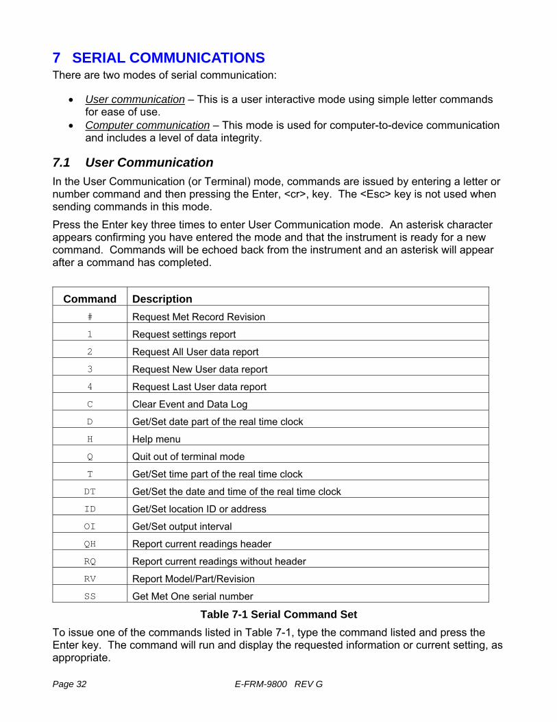
7.1 User Communication In the User Communication (or Terminal) mode, commands are issued by entering a letter or number command and then pressing the Enter, <cr>, key. The <Esc> key is not used when sending commands in this mode. Press the Enter key three times to enter User Communication mode. An asterisk character appears confirming you have entered the mode and that the instrument is ready for a new command. Commands will be echoed back from the instrument and an asterisk will appear after a command has completed.
Command Description # Request Met Record Revision
1 Request settings report
2 Request All User data report
3 Request New User data report
4 Request Last User data report
C Clear Event and Data Log
D Get/Set date part of the real time clock
H Help menu
Q Quit out of terminal mode
T Get/Set time part of the real time clock
DT Get/Set the date and time of the real time clock
ID Get/Set location ID or address
OI Get/Set output interval
QH Report current readings header
RQ Report current readings without header
RV Report Model/Part/Revision
SS Get Met One serial number
Table 7-1 Serial Command Set To issue one of the commands listed in Table 7-1, type the command listed and press the Enter key. The command will run and display the requested information or current setting, as appropriate.

E-FRM-9800 REV G Page 33
For example, to view the current date setting you would type the letter D followed by the Enter key. You would then see the current date reported. The sequence would appear like this: D<cr> D 2013-01-18<cr><lf>
To change a setting, the typical sequence is to type the command, press the space bar one time, enter the new value in the same format that is displayed when checking the setting, and then pressing the Enter key. Continuing the example above, to change the date setting you would type the letter D, space, and then the current date in YYYY-MM-DD format followed by the Enter key. You would then see confirmation of the new date reported. The sequence would appear like this: D 2016-01-30<cr>
D 2016-01-30<cr><lf>
Pressing <Esc> or Q<cr> will exit terminal mode. For a detailed listing of all command formats, consult the E-FRM 7500 document contained on the CD included with your sampler or contact the Met One Instruments service department. See section 1.2.
7.2 Computer Communication In the Computer Communication mode, character echo is suppressed. This means if you are issuing commands in this mode using a keyboard, you will not see what you are typing displayed on the screen. The command format includes a checksum to verify data integrity. The mode is entered whenever an <Esc> character is sent to the instrument. Commands are issued using the following format: <Esc>Cmd p1 p2*cs<cr>
Computer commands are prefaced with an <Esc> character followed directly by a command (Cmd).. After the command there can be zero or more parameter field (p1 and p2) where each field is separated by a space. The end of the message is signaled by the Checksum Delimiter character (*) followed by the checksum itself (cs). Finally, the command is terminated with a carriage return (<cr>). A computer command example requesting the Model/Part/Revision numbers would look like this: <Esc>RV*1234<cr>
All command responses are terminated with a checksum. The above command response would have this format: RV 092, 99999-1, R9.9.9*1234<cr><lf>
For a listing of all command formats and additional in depth Computer Communication details, consult the E-FRM 7500 document contained on the CD included with your sampler or contact the Met One Instruments service department. See section 1.2.

Page 34 E-FRM-9800 REV G
8 ACCESSORIES and PARTS
8.1 Consumables, Replacement Parts, and Accessories The following parts are available from Met One for maintenance, replacement, service, and upgrades. If unsure about a part you need, please contact the Service department and provide the serial number of your E-FRM. Some of these parts require technical skills or special considerations before use or installation. Consumables
Description Part Number Graphic Filter, 47MM, PTFE, FRM 460122 Filter Cassette, FRM, 47 MM 460128 Fan Filter, Replacement, 5 PACK 560001 Silicone O-Ring Grease, mini packet 995712 Calibration & Service Tools
Description Part Number Graphic
Flow Inlet Adapter Kit (Leak Test Valve) Includes short inlet tube adapter. BX-305
Volumetric Flow Calibration Kit (BGI deltaCal™) Flow, Temp, and Pressure Reference Standards Met One recommended flow meter
BX-307
Vacuum Pumps & Pump Parts
Description Part Number Graphic Pump, Vacuum 680897 Muffler, Pump Exhaust 580293

E-FRM-9800 REV G Page 35
Flow System Components Description Part Number Graphic
Flow Sensor, Mass, 0-20 LPM, Internal Assembly 81892
Automatic Flow Controller 82099
Inline Filter 580299
Electrical & Electronic Parts
Description Part Number Graphic
Pressure Sensor Circuit Board 80940-1
Control Panel Assembly 81151

Page 36 E-FRM-9800 REV G
Inlet Components Description Part Number Graphic
PM10 Size-Selective Inlet Head, EPA Specified BX-802
TSP Sampling Inlet, with insect screen BX-803
PM2.5 Sharp Cut Cyclone BX-807
PM2.5 Very Sharp Cut Cyclone, BGI Inc. VSCC™ Used for PM2.5 FEM monitoring BX-808
PM2.5 URG-2000-30EGN Cyclonic Separator Used for PM2.5 FEM monitoring BX-809
PM2.5 WINS Impactor BX-804 O-Rings, BX-807 SCC Cyclone, set of 6 720097 O-Rings, BX-808 BGI Cyclone, set of 8 720105 O-Rings, BX-809 URG Cyclone 720228 O-Rings, PM10 Head, set of 3 8965 O-Ring, Inlet Tube Receiver, 2 required. 720069
Meteorological Sensors
Description Part Number Graphic Ambient Temp Sensor Assembly -50 To +50 Deg C 80866 Communications Options & Accessories
Description Part Number Graphic FRM-Comm Firmware CD 81264

Page 37
Audit Sheet
Model: Serial Number:
Audit Date: Audited By:
Flow Audits Flow Reference Standard Used: Model: Serial No: Calibration Date: Temperature Standard Used: Model: Serial No: Calibration Date: Barometric Pressure Standard Used: Model: Serial No: Calibration Date:
Leak Check Value: as found: lpm as left: lpm
E-FRM Ref. Std. E-FRM Ref. Std. Ambient Temperature: as found: C C as left: C C N/A Barometric Pressure: as found: mmHg mmHg as left: mmHg mmHg Flow Rate (Actual Volumetric): as found: lpm lpm as left: lpm lpm N/A
Mechanical Audits
Fan filters clean: as found as left PM10 particle trap clean: as found as left
PM10 drip jar empty: as found as left PM10 bug screen clear: as found as left
PM2.5 particle trap clean: as found as left Pump muffler unclogged as found as left
Error Date Time Error Date Time
1 4 2 5 3 6
Audit Notes:

Page 38 E-FRM-9800 REV G
Manual Notes: