Embed Size (px)
Citation preview

construction United Status ArmyCors f ngner* TECHNICAL REPORT M-297Sm.9t, A-~y
e gn eigSe,.,ng th, Not#-n November 1981
research New Roofing Concepts in the Military Construction Process
laboratory
EVALUATION OF SPRAYED POLYURETHANE FOAM ROOFING
AND PROTECTIVE COATINGS
byMyer J. Rosenfield
19~32
A
Approved for u&ilgeh'ution unlimited.

. . 4
The contents of this report are not to be used for advertising, publication, orpromotional purposes. Citation of trade names does not constitute anofficial indorement or approval of the use of such commercial productsThe findings of this report are not to be construed as an official Departmentof the Army position, unless so designated by other authorized documents.
DESTROY THIS REPORT WHEN IT IS NO LONGER NEEDEDDO NOT RETURN IT TO THE ORIGIN 4 TOR

BestAvai~lable
Copy

UNCLASSIFIEDSECURITY CLASSIFICATION OF THIS PAGE (W~hen Date Entered)
REPORT DOCUMENTATION PAGE READ INSTRUCTIONSBEFORE COMPLETING FORM
I. REPORT NUMBER 2. GOVT ACCESSION NO. 3. RECIPIENT'S CATALOG NUMBER
CERL-TR-M-297 T - - 1 (.. ,4. TITLE (and Subtitle) S. TYPE OF REPORT , PERIOD COVERED
EVALUATION OF SPRAYED POLYURETHANE FOAM ROOFINGAND PRUTECTIVE COATINGS FINAL
S. PERFORMING ORG. REPORT NUMBER
7. AUTNOR(e) 8. CONTRACT OR GRANT NUMBER(.)
Myer J. Rosenfield
9. PERFORMING ORGANIZATION NAME AND ADDRESS I0. PROGRAM ELEMENT, PROJECT, TASK
U. S. ARMY AREA & WORK UNIT NUMBERS
CONSTRUCTIONI ENGINEERING RESEARCH LABORATORY 4A762731AI41-A-044P.O. Box 4005, Champaign, IL 61820
II. CONTROLLING OFFICE NAME AND ADDRESS 12. REPORT DATENovenber 198113. NUMBER OF PAGES
5414. MONITORING AGENCY NAME & ADDRESS(i dif ferent from Controllind Office) IS. SECURITY CLASS. (of thie report)
UnclassifiedISO. DECLASSIFICATION/DoWNGRADING
SCHEDULE
1a. DISTRIBUTION STATEMENT (of tis Report)
Approved for public release; distribution unlimited.
17. DISTRIBUTION STATEMENT (of the abetract emtered In Block 20, if different from Report)
IS. SUPPLEMENTARY NOTES
Copies are obtainable from the National Technical Information ServiceSpringfield, VA 22151
19. KEY WORDS (Continue on reveres aide If neceeeay and Identify by block number) .
roofs
polyurethane resinsfoam
240 AwiRAC m Wresm eit N tmssy d e eonif by block number)
This report documents a study to evaluate sprayed polyurethane foam (PUF) roofingand protective coatings for use in reroofing at Army installations. Manufacturers, fieldapplications, and literature were surveyed to identify advantages abd disadvantages asso-ciated with the use of these systems. -
It was found that the service life of this type of roof system depends on the skill of theapplicator and the capability of the coating material to resist the effects of climate and~~~~weather. ,
JANl143 t NrM~lSm T UNCLASSI F iFOSECURITY CLASSIFICATION OF THIS PAGE (Rhe I)ter Fnted)
1473 EDIIOWOIN~6UISmOLTE UCLASIFID ~~64'~ 7

UNCLASSIFIDSECURITY CLASSIFICATION OF THIS PAGE(WMn Data gntte-d)
BLOCK 20 CONTINUED
. , PUF can be used as an alternative to conventional built-up roofing (BUR) for newroofs, or to replace failed roofs. However, because these systems are relatively new(and long-term durability statistics are not available), they should only be used on care-fully selected Army roofs. New construction is limited to the use of silicone-coatedPUF over concrete roof decks, as required by Corps of Engineers Guide Specification(CEGS)-07540.
UNCLASSI F IED
r. ...rr *rfl. ,,, ~ .
FOREWORD
This investigation was performed for the Directorate of Military Programs, Office ofthe Chief of Engineers (OCE), under Project 4A762731AT41, "Military Facilities Engi-neering Technology"; Task A, "Military Cronstr-uction";orRkT7iI 044,, "New RoofingConcepts in the Military Construction Process." The OCE Technica onitor is MarvinBeck, DAEN-MPO-B.
This study was performed by the Engineering and Materials Division (EM), U.S. ArmyConstruction Engineering Research Laboratory (CERL). Dr. R. Quattrone is Chief of EM.
Appreciation is expressed to Dr. Robert L. Alumbaugh of the U.S. Navy Civil Engi-neering Laboratory, and Mr. Bernard V. Jones of the U.S. Bureau of Reclamation fortheir contributions to and review of the technical content of this report.
Figures 2 through 25 are official U.S. Navy photographs.
COL Louis J. Circeo is Commander and Director of CERL, and Dr. L. R. Shaffer isTechnical Director.
3

CONTENTS
Page
DD FORM 1473 1FOREWORD 3LIST OF TABLES AND FIGURES 5
1 INTRODUCTION ........................................... 7BackgroundObjectiveApproachMode of Technology Transfer
2 INSTALLATION OF FOAM ROOFING ON VARIOUS SUBSTRATES ........ 7Criteria for Foam ApplicationApplication to Concrete Roof DecksApplication to Wood Roof DecksApplication to Steel RoofsApplication to Fluted Steel Roof Dcks
Advantages and DisadvantagesProper Application Procedures
3 COATINGS USED ON SPRAYED FOAM .......................... 24Criteria for CoatingsAvailable CoatingsAdvantages and DisadvantagesProper Application Procedures
4 DISCUSSIONS WITH OTHER GOVERNMENT AGENCIES ............. 38Naval Construction Battalion CenterBureau of Reclamation
5 RESULTS OF SITE VISITS ................................... 40Site DescriptionsSummary of Site Visits
6 CONCLUSIONS ........................................... 48
REFERENCES 54DISTRIBUTION
4

TABLES
Number Page
I Impermeable Coatings 27
2 Permeable Coatings 29
3 Foamed Roofs Inspected 41
FIGURES
Number Page
I The Relationship Between Density and Compressive Strength of Foam 8
2 Smooth Foam Surface 10
3 Orange Peel Foam Surface 10
4 Coarse Orange Peel Foam Surface 11
5 Verge of Popcorn Foam Surface 1
6 Popcorn Foam Surface 12
7 Treebark Foam Surface 12
8 Pinholes or Blowholes in Foam Surface 16
9 Rippling in Foam Surface 16
10 Isocyanate-Rich Surface 18
I I Resin-Rich Surface 18
12 Foam Application Over Wet Surface 20
13 Moisture Meter 20
14 Pyrometer 21
15 Foam Application Over Cold Surface 22
16 Foam Application Over Hot Surface 23
17 UV Degradation of Foam 23
18 Coating Over Smooth Orange Peel 32
19 Coating Over Orange Peel 32
20 Coating Over Coarse Orange Peel 33
5

FIGURES (con't)
Number Page
21 Coating Over Verge of Popcorn 33
22 Coating Over Popcorn 34
23 Coating Over Treebark 34
24 Pinholes in Coating 35
25 Granules Over Coating 37
26 Variation in Foam Surface Texture 42
27 Ponded Water on Roof 42
28 Ponded Water on Uncoated Foam 43
29 Variation in Foam Surface Texture 44
30 Spots Where Water Had Ponded 44
31 View of Roof Showing Dirt in Valley 45
32 Deterioration of Coating Due to Insufficient Thickness 45
33 Damage to Coating From Unknown Missile 46
34 Variation in Foam Surface Texture 46
35 Popcorn Surface of Foam 47
36 Failure of VIP-4000 Coating 47
37 Failure of Performance Polymer Coating Where Refoamed 49
38 Delamination of Performance Polymer Coating From VIP-4000 49
39 Gaco Western U66, 2 Days Old, Not Bridging Crack in Foam 50
40 Ponded Water From Leak in Cooling Tower 50
41 Pond Drained by Cutting Trough in Foam 51
42 Footprints Visible on 1-1/2 pcf Foam 51
43 Hail Damage to Diathon Coating 52
44 Saturated Foam Under Diathon Coating 52
45 Algae Growing on Sloped Roof 53
6

EVALUATION OF SPRAYED Io existing Corps ol [ngilice (Giuide specilil:lnPOLYURETHANE FOAM ROOFING ('W;S)-07540.AND PROTECTIVE COATINGS
This report documents step 1, above.
INTRODUCTION Mode of Technology Transfer
Background If the results of this study show that PUF roofingsystems can be used at Army installations. CEGS-
Most Army facilities use conventional roofing 07540, Elastorneric Roofing. I"uid-Applied, will besystems, such as built-up roofing (BUR), that are revised to include application on decks other than con-expensive and complicated to construct. Often, these crete and use of coatings other than silicone.
systems are comparatively short-lived, resulting in highlife-cycle roofing costs that are difficult for alreadyoverburdened Army operation and maintenance bud- INSTALLATION OF FOAM ROOFINGgets to absorb. Therefore, the Directorate of Military 2 ON VARIOUS SUBSTRATESPrograms has asked the U.S. Army Construction Engi-neering Research Laboratory (CERL) to identify alter- Criteria for Foam Applicationnative, easy-to-install roofing systems that can improvethe performance of Army roofing while reducing life- ire Safetycycle costs.
Regardless of the roof deck being covered, sprayedObjective PUF roofing systems should be designated Class A. B.
or C by Underwriters' Laboratories (UL) StandardThe overall objectives of CERL's roofing studies are 790.1 In addition, combustible roof decks, including
to: (1) evaluate innovative roofing systems and mate- metal decks, are required to have a UL roof deckrials to determine alternatives to BUR systems, (2) pro- construction classification or a Factory Mutual (FMIvide a means to improve Army roof performance and Class I classification. These requirements are includedreduce life-cycle costs, and (3) develop guide specifica- in Department of Defense (DOD) Construction Criteriations for selected alternative systems. Manual DOD 4270.1-M. 2 Note that this manual lists
2-in. (51-mm) tongue-and-groove wooden decking as aThe specific objective of this report is to document noncombustible roof deck.
an investigation into the use of one alternative system,polyurethane foam (PUF) with a suitable elastomeric Wind Resistancecoating.
The roofing system should adhere tightly to the sub-Approach strate. A minimum adhesion of 95 percent is recom-
mended.3
This investigation is being conducted in the follow-ing steps: Weather Resistance
1. Survey of literature, manufacturers, and field Foamed urethanes are susceptible to damage by sun-applications to identify advantages and disadvantages light and water (freeze-thaw) and must be coated toassociated with the use of PUF roofing systems. prevent deterioration.
2. Construction of PUF roofing systems at selectedArmy installations. I Tests for Fire Resistance of Roof Covering Materials. tL
Standard 790 (Underwriters' Laboratories l UL . 1978).3. Evaluation of the design, construction, and post- 2 Construction Criteria Manual, DOD 4270.1-M (I)cpart-
construction performance of the test roofs over 2 years. nient of Defense, October 1972).3 W. C. Cullen and W. J. Rossitcr, Guidelines for Selection
4. Determination of the suitability of PUF for use of and Use of Foarn Poltyurethane Rooffng Svstems NBS Tech-in Army roofing systems and the subsequent revisions nical Note 778 (National Bureau of Standards. Ma) 19731.
7
density and compressive strength ol loam is giveii inFigure .'
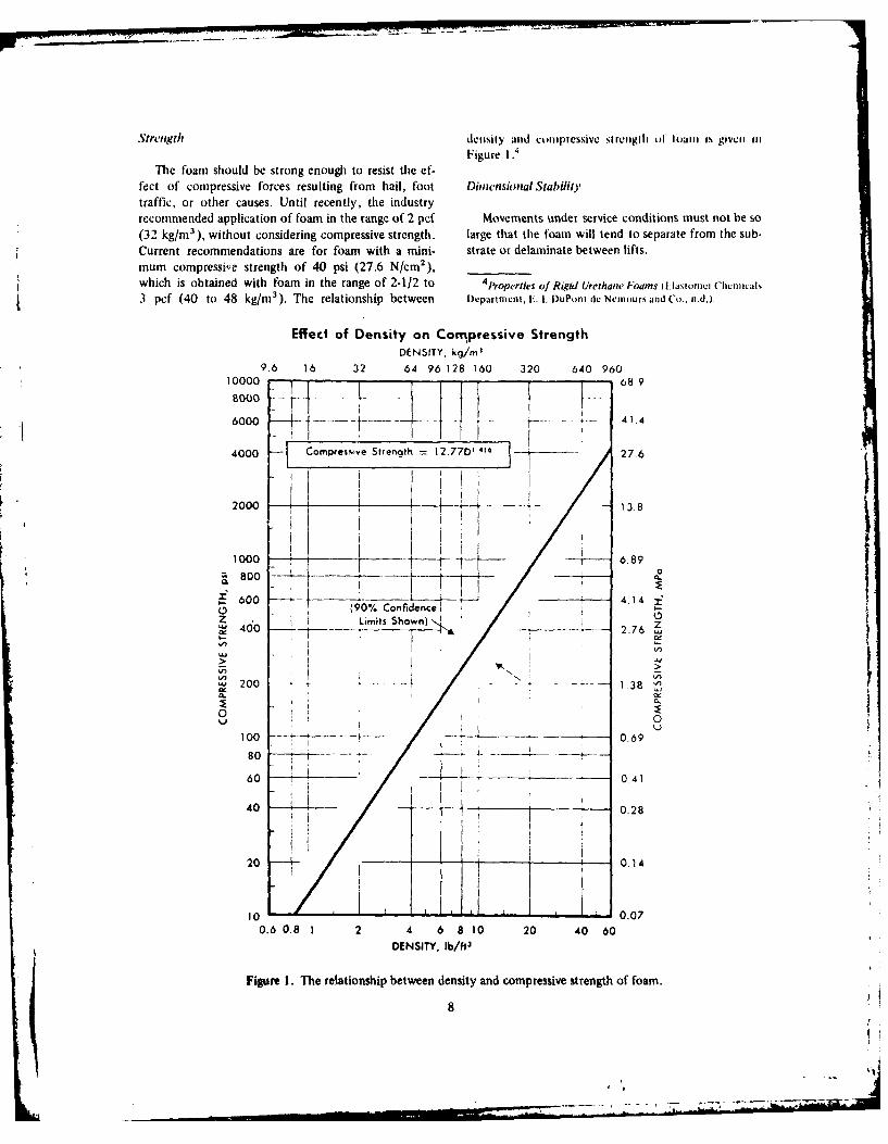
The foam should be strong enough to resist the ef-fect of compressive forces resulting from hail, foot Dimensional Stabilitytraffic, or other causes. Until recently, the industryrecommended application of foam in the range of 2 pcf Movements under service conditions must not be so(32 kg/m), without considering compressive strength. large that the foam will tend to separate from the sub-Current recommendations are for foam with a mini- strate or delaminate between lifts.mum compressive strength of 40 psi (27.6 N/cm 2 ),which is obtained with foam in the range of 2-1/2 to 4
Properties of Rigid Urethane Foams (l.latonicr Chrnica
3 pcf (40 to 48 kg/m 3 ). The relationship between I)epartmcnt. E. I. DuPont de Nem,,urs and Co., n.d.).
Effect of Density on Compressive StrengthDENSITY, kg/m'
9.6 16 32 64 96 128 160 320 640 960
10000 68000 -V
6000_ 41.4
4000- Compres."ve Strength 12.770 4 27.6
2000 13.8
4IT
1000 17Vv 6.89
600 ------- 4.14 j(90% Confidence i
Z Limits Shown)'. z- 2.7
200 1 --- - 1.38
60 0.41
40 0.28
20 - 0.14
10 0.07
0.6 0.8 1 2 4 6 8 10 20 40 60DENSITY, Ib/ft
3
Figure i. The relationship between density and compressive strength of foam.
8

Insulation CEGS-07540 (formerly (1-220.13) is limited to apph-cation of foam over structural concrete decks in nc\
Insulation values must meet the requirements of construction.5 Application to inetal roofs is a reiroi!.DOD 4270.1-M (U-value of 0.05 or R-value of 20). and is beyond the scope of CEGS-07540.
Drainage If the deck is clean and dry, f.ee of all form oil.form-release agents, or other grease or oil. then the
Foam should be installed with a minimum slope of foam can be applied directly to the deck. Although1: 100, and the surface should be flat enough that only wood float or trowelled finishes may be foamed di-small, shallow pools of water (bird baths) will remain rectly, CEGS-07540 requires a broomed finish so thatafter a rain. a better bond may be attained. Decks which cannot be
Cell Structure cleaned of residual oil or grease, or which contain rem-nants of old asphalt vapor retarders, may need to be
The foam should have a uniform structure, of which primed. The various foam manufacturers state the con-
90 percent consists of small spherical closed cells. This ditions under which primers must be used before foamis applied. Many even specify and offer a particular
structure is necessary to provide the required insulation pier fo n ve peir and offer asparticula
value and to prevent absorption of water. primer for use with their foamn. Cutback asphalt, such)as American Society for Testing and Materials [ASTMJ
Surface D 41,6 should dry from 2 to 4 weeks before foaming.Otherwise, the heat of reaction of the foam will cause
The foam surface should be as smooth as possible so the primer to lose its bond to the concrete, and the
that the coating, when applied, will cover properly and foam will ultimately float off. Some asphalt primers
uniformly. Foam surfaces commonly termed "smooth" have a high paraffin content, which affects bonding of
(Figure 2), "orange peel" (Figures 3 and 4), and "verge anything applied on them. A primer recommended by
of popcorn" (Figure 5) are acceptable. "Popcorn" the foam manufacturer should be used.
(Figure 6) or "tree bark" (Figure 7) surfaces are notacceptable and should not be coated. The normal sur- Lightweight concrete and poured-in-place gypsum
face texture to be expected is "orange peel." are not satisfactory substrates for application of foambecause: (1) their cohesive strength is much less than
Vapor Retarder the adhesive bond strength between the surface and thefoam, and (2) there is a tendency to apply the foam
Installation of a vapor retarder between the sub- before the substrate is thoroughly dry. The moisturestrate and the foam depends on the environment in the will cause severe problems since it tends to evaporate.building. Moisture flowing through the roof must be CEGS-07540 specifically prohibits foam application toanalyzed carefully to see whether there will be a signifi- lightweight concrete.cant quantity moving from the building into the foam,and whether it will subsequently condense or freeze Application to Wood Roof Decks
within the foam or beneath the coating. Conditionsthat normally suggest a vapor retarder for a BUR also Roofs consisting of sprayed PUF apphed to woodsuggest one for a foam roof system. If the analysis decks are designated either Class B or Class C by UL.reveals that a vapor retarder is needed, three types are This does not mean that only wood decks are classifiedavailable: built-up, made of felt and hot asphalt; sheet- Class B or C; noncombustible decks itay also bearapplied, of impervious elastomeric membrane; or fluid- these ratings. Details may be found in UL's Buildingapplied, of materials such as butyl rubber, neoprene Materials Directorj. Wood deck constructions tested
rubber, and chlorosulfonated polyethylene. The type by UL consist of foam applied to plywood of various
of roof deck often indicates the best vapor retarder thicknesses, but at least 3/8 in. (10 mm).
to use.
SElastomeric Roofing, Fluid Applied, Ct(;S-07540 iDx-Application to Concrete Roof Decks partment of the Army IDAI, Office of the Chief ot neincers
IOCEI, April 19.80).Until recently, installing PUF roofing on concrete 6Asphalt Primer Used in Roofing. Damp.Proofing and
roof decks was the only method rated Class A by UL. Waterproofing, ASTM D 41-78 (American Soocty tor Teomng
Because the Corps of Engineers requires that all roofs and Materials I ASTMI, 27 MNla 1980).meet Class A requirements, regardless of material used, 7Building Materials Director) (1L. January 1980).
9

L4.
10 r
. bi
%po
Fiue3 inepdfa itA4
K ~"10

Figure 4. Coaise orang~e peel 'l ~i t..t
Figure 5. V"erge' of pp mhil sltt C.
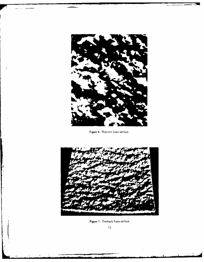
Figure 6. Popcorn foam surface.
Figure 7. Treebark foamn surface.
12

Although foam may be applied to tongue and Class 90 criteria, but have not been investigated forgroove decking, sheathing, or planking, it is advisable fire resistance. No. 74 is direct application of foam toto overlay [ie deck with plywood to eliminate future the deck, with ibam filing the flutes. No. X2 is wtilhproblems caused by potential shrinkage cracking from formed shapes of foam placed in the flutes hefoicdrying or aging. The plywood must be firmly nailed to sprayed foaii is applied. This construction is notthe deck and printed according to the foam manulac- authorized for Army use because the ('lass A criterionturer's recommendations. Joints larger than 1/4 in. is not met. To meet Class A requirements, a themial(6 mm) should be caulked or taped before foaming. barrier must first be mechanically fastened to the deck.
and the foam applied to the barrier. A satisfactory bar-It is unlikely that foamed roofing will be applied to rier is I-in.-thick(25-mm)perlite board, or I/2-in.-thick
wood decks on any Army buildings because this con- (13-mm) waterproofed gypsum board. A vapor retarderstruction will not meet UL Class A requirements. may or may not be required between the thermal bar-
rier and the foam.
Application to Steel Roofs
Advantages and DisadvantagesFor several years, the U.S. Navy Civil Engineering
Laboratory (CEL) has been applying PUF roofing CERL Technical Report M-263 describes the adva:-directly to steel roofs of Butler Rib-type buildings. tages and disadvantages of foamed-in-place roofingRealizing that this construction may meet UL Class A systems; these points are summarized below.' 0
requirements, CEL asked that UL perform its tests inaccordance with UL 790 and UL Subject 1250, "Out- Advantagesline of the Proposed Investigation for Roof Deck Con-structions." Results of these tests indicate that this 1. Insulation capability. Polyurethane foams are theconstruction does meet Class A requirements 8 A]- best insulating materials now available for use in con-costhuhion a die number o as A catir ngs. were struction. Since they are good insulators, they can pre-actually tested (two foams and two coatings, for a total vent excessive thermal movement in metal buildingsactullytesed twofoas ad to catigsfora ttal when applied on top of existing roof systenis and onof four different systems), the way is now open to per- when aerform similar tests on other combinations of foams and exterior surfaces.coatings. UL has listed this construction as Roof Deck 2. Ease of application and repair. PolyurethaneConstruction No. 136.9 At least six different foams foams are multicomponent systems that are appliedand eight different coating systems are now classifiedas m eti g t is onst uct on. Sys ems ist d u der w ith a special spray apparatus. Tw o layers (lifts) arcas m eeting th is construction. System s listed under re o m n d to ns e a d q u e s al D m g drecommended to ensure an adequate seal. DamagedRoof Deck Construction No. 136 meet the fire safetyrequirements of DOD 4270.1 -M. areas are easily repaired by removing affected sectionls
and refoaming. However, the skill of the operator and
The surface to be coated should be clean and dry, weather conditions are extremely important.free of all rust, loose scale and paint, grease, oil, or 3. Ease of coverage. Since tile foam forms a ho.other foreign matter. Priming may be required; if so, mogeneous layer, it can be used to bridge cracks andit should be performed according to the recommenda- irregularities in the substrate. The foaned-in-place sys-tions of the foam manufacturer or installer. tem is also self-flashing and will seal readily at parapet
walls and around projections.Application to Fluted Steel Roof Decks
4. Lightweight. Because foam systems are muchApplication of PUF directly to fluted steel roof lighter than conventional BUR systems, various densi-
decks does not now meet either UL Class A or FM ties and thicknesses of foam can be applied to meetClass I requirements. UL Roof Deck Constructions Nos. many requirements for insulation, impact resistance, or74 and 82 have been tested for wind uplift and meet roof traffic. However, care must be exercised to pre-
vent disbonding when applying different density foamsover one another.
8 Fire Tests of Polyurethane Foam Roof Deck Constructionon Steel Decks, Report CR 79.004 (Civil Engineering Labora-tory, Naval Construction Battalion Center, December 1978). 10E. Marvin, ct ,it.. I:vahation ol Altrnatirc Rerooifig
9"Construction No. 136," Building Materials Director) Systems, Interim Report M-263/ADA071578 (U.S. Arm (on-
WUL. January 1980). struction Engineering Research Laboratoo, June 19791.
13(s

l)i .t ap"pilat i t) suit ably pipaed emistilg (0. lleg uaii surlaces. l. iiiii y ., tc ,li (Ib 1141 gci
tool. A welteied il da iUaged rool call, in effect, he er:lly piovide anr even Iol i ltacI'. lli, ,esil v, it
stabilized b1 loan application, within certain limila- stirface which can contain smnall de pressitnis (hii dtions. baths) and other irregularities where water tends to
pond ;!"ter rain storms. To winimize this effect andI)isadian tages other difficulties, such as overspray, skilled foaming
system operators are required.I. Susceptibility to ultraviolet (UV) radiation and
weather degradation. After curing, foamed-in-place sys- Proper Application Procedures
tems must have a suitable elastomeric coating, such asacrylics, silicone rubbers, butyl/Hypalons,* Hypalon Questions related it) loam qualit . surface tettuie.mastics. catalized urethanes, and other weather- and equipment and materials, application, exposure to sull-UV-resistant coatings. In addition, these systems must light, and thickness measurement have been discussedbe kept coated throughout the life of the roof to pre- by Coultrap in a recent report.' Tile remainder ot flus
vent UV- or weather-induced degradation. chapter consists of material from his report.
2. Low compressive and tensile strength. A com- I-oam Qualitypleted loam roof is subject to damage from hail andtool traffic: in some areas, birds and rodents also can Once the substrate or surface has been correctly
cause damage. prepared, proper inspection will frequently he a deter-tining factor in the success or failure of a urethane
3. Preparation. To ensure proper adhesion, sub- foam roof application. Many factors must he consid-
strates must be thoroughly prepared to receive foamed- ered and observed to assure application of high quaityin-place systems. Such preparation includes removal of foam. It is also important to recognize that the foamany loose or flaking section of an existing roof. Foam insulation applied is the base for the ultimate applica-cannot be mechanically fastened, and will not adhere tion of a protective coating system. Thus. the qualityto dirty, wet, or oily surfaces. of the finished system depends primarily on the proper
application and properties olf the in-place foam.4. Flammability. Since foams are organic, they will
burn, however, the full extent of the fire hazard they Proper application of sprayed foam requires a highlyrepresent has not yet been resolved. In particular, the skilled and trained operator. Of course, equipment anddirect application of foan over fluted metal decks in materials available with modern technology can pro-habitable buildings is actively being researched but has vide satisfactory results. But the contractor's abilit%not yet been approved. Foam roofs may be placed over and willingness to exercise proper controls over variousmetal decks if a suitable fire barrier is provided be- factors at the job site frequently are the difference be-tween the deck and the foam layer. Direct application tween success and failure. Therefore, from the outsetof foam to prefabricated steel, Butler Rib-type build- the contractor must have the proper equipment andings is now designated by UL as Class A, and thus materials at the job site. and must understand condi-meets the requirements of DOD 4270.1 -M. tions necessary for good foam application. The mini-
mum acceptable levels of quality should be established5. Overspray. Foam should not be applied when with the contractor before the foam application is
wind speeds are above 12 mph (19.2 km/hr) unless started.wind screens are used. All spray operations should besuspended when wind speeds exceed 20 to 25 mph (32 Surface Texture and Qualityto 40 km/hr). The influence of excessive wind duringspraying canl: tI) make it difficult to control foatmspra in cal: 1) mke t dffiult o cntrl farn One of the best visual indicators of a good foamsurface texture and. to a lesser extent, foam thickness, on of the bevanca of a god oand (2) cause an overspray which can damnage adjacent application is the appearance of the surface profile or
texture. Surface texture of sprayed foam is a functionvehicles or buildings. However. foam overspray is nomore a problem than overspray from a paint spray
operation.
ItKcith It. (out ral. ftinciph' 0] t Uretham Foam Roof*lypallut i k a reeistcred trademark of' F. I. I)uPont de lpplication. PO No. 79-MR-461 (ivil Lngineerine I aborahlr.
Nemo,'ur & (o Navat (',nstruction Batta,,,rr Center. June 1980).
14

tributing factors: (I) equipment adjustments, (2) envi- For example, contractors frequently refer to a 4-second,ronmiental effects, and (3) applicator skills. 0-second, or 8-second foam. These rates of reaction
(cream times) can be changed to some degree by mate-Terms used to describe foam surface texture and rial temperatures, but it is the responsibility of the con-
quality are listed below: tractor to select a system with an appropriate "creamtime" for the environment where tie foam is to be
Smooth - see Figure 2 applied. Selection of an improper cream time canOrange peel - see Figure 3 usually be judged by certain surface texture factors.Coarse orange peel - see Figure 4 If the cream time is too short and the environmentalVerge of popcorn - see Figure 5 conditions are too warm, the applicator will havePopcorn - see Figure 6 difficulty obtaining a smooth or orange peel surface.Treebark - see Figure 7 Typically, the texture will be coarse orange peel andPinholes or blowholes - see Figure 8 beyond, depending on the conditions. A foam with aRippling - see Figure 9 faster or shorter cream time will not be quite as sensi-
tive to winds during application; however, the benefitIn this discussion, it is assumed that all equipment is is marginal. It is better to use a foam system that is
operating properly and that material ratios are correct, proper for the temperature, and to limit the applica-It is also assumed that the equipment has variable con- tion to acceptable wind conditions.trols for adjusting material pressures and temperatures.
When the cream time is too long, the surface texture
Equipment Adjustments. Given the above assump- of the foam may be very smooth, but the surface skintions, the correct temperature and pressure of the ma- may be quite dense, and the density of the foam mayterials contribute most significantly to proper spray be affected. Consequently, more spray passes will bepattern. A full and proper spray pattern allows the required to obtain the desired foam thickness. A longspray applicator to make uniform passes of mixed ma- cream time will also present problems when the foamterial that rises steadily as it is applied to the advancing is sprayed on vertical surfaces, such as parapet walls.foam front. For a given pressure, materials that are too flashings, and cants. The material will run or sag beforecold will cause a rather narrow spray pattern which proper foaming begins, which tends to lead to treebarkdrives into the rising deposited foam and causes dii- in extreme cases. When foam is applied to vertical sur-pies, holes, roughness, or ridges. The overall effect is faces, it should foam straight out with no visible slumpa popcorn or, in an extreme case, a treebark foam or sag. Foam with a long cream time is more suscep-surface. If the temperature is only slightly low, adjust- tible to wind effects on the surface, and in extremements of the material pressure or the spray gun valving cases, a ridging or rippling effect will occur, much therod can correct the pattern, same as that from wind on water.
If the materials are too hot, the foam deposited will Aside from temperature, winds often create a mostIf te mteralsaretoohotthefoa deosied ill difficult situation. As indicated above, wind not only
react too fast to permit levelling, and a "verge of pop- affect suace tex ted aplie d o t al
corn" surface will tend to develop, even though the affects the surface texture of' applied foam but alsospray pattern is full. causes overspray, which is a serious problem. Overspray
can damage surfaces not intended to be sprayed, suchas other buildings. vehicles, and equipment. and exces-
Part of the training of a skilled foam applicator is sive overspray deposited on foam already in placeto recognize spray pattern problems and to adjust for causes an irregular surface which interferes with subse-them. The symptoms listed above should help one quent foam or coating application. Practical experiencerecognize the causes of foam with improper texture. has shown that foam should not be sprayed when wind
speeds are over 12 mph (19 km/hr) without some formEnvironmental Factors. Modern spray foam mate- of windshield, and should not be sprayed at all when
rial systems have been formulated to provide different wind speed is over 25 mph (40 km/hr). It is importantspeeds of reaction at some given or expected tempera- to evaluate damage that might be caused by oversprayture of the surface upon which the foam will be ap- combined with the surface texture quality of the foamplied. This factor is called the "cream time," measured oeing applied. Some relief can be obtained from over-in seconds of time at a given temperature of applica- spray problems by proper masking protection. but it istion that the "A" and "B" components will begin to essential that the quality of the foam applied underreact or foam after being mixed through the spray gun. windy conditions be carefully controlled. Rippling
15

Figuree PRllPIles
kWO

(Figure 9) can result from spraying at excessive wind momentary metering pump cavitation problems; thus,
speeds. poor quality foam will be deposited in relatively smallareas. At times, an operator will see a short break in
Applicator Skills. Given proper materials, equip- the spray pattern, decide that nothing is wrong, andment, and conditions of application, the skill of the proceed with the work. However, if constant fluctua-applicator of the foam is one of the most important tions are observed in the spray pattern, or if the ap-factors in determining the surface texture and unifor- pearance of the foam being applied is abnormal, themity of foam thickness. It is important to determine work should be stopped until the cause is determined.as soon as possible after foam application begins thatthe applicator possesses the skills and experience to Early detection of poor foam quality can providemake a proper application. These skills must include an indication that the materials being sprayed are toothe knowledge of proper adjustments to the equip- old or have deteriorated because their chemical shelfment, the foam material being used, and the limits life has expired. These materials usually should be re-that environmental factors may impose. The appli- placed. Obviously, the problem can be avoided if it iscator must also be willing to follow proper procedures. determined, before application, that the materials are
within the shelf life recommendations of the supplier,It cannot be emphasized too strongly that foam ap- and have been stored properly on the job site.
plication should be stopped immediately if the resultsindicate that the applicator is not skilled. It is far bet- Excess Isocyanate or "A" Component. The effectster to prevent bad application than to correct such of foam applied which is off-ratio or misproportionedconditions after the foam is in place. One can soon tell with respect to the isocyanate component are morehow competent the applicator is by observing whether difficult to discover unless the condition is extreme. Inthe foam passes are applied to a uniform thickness of fact, foam applied with slight excess of isocyanate is1/2 in. to 3/4 in. (13 to 19 mm) per pass, and whether not as seriously affected as when there is excess polyol,the surface texture of the foam exhibits an acceptable because in the former case, the polyol is totally reacted."smooth" or "orange peel" finish. Application should The more extreme condition of excess isocyanate
also be judged by the uniformity of foam applied to (Figure 10) will produce one or more of the followingtransition points of flashings, cants, roof edges, equip- effects:ment mountings, etc. A good applicator will properlyoverlap the spray pattern, which results in a uniform - Dark colorplanar level of the foam, free of "ridging" or "rippling" - Smooth hard surface(sometimes referred to as a "wash board" effect). - Irregular glassy cell structure
- Friable and/or brittle foam
It is vital that the acceptable level of foam quality - Improper densitybe established with the applicator(s) during the early - Improper rise.stages of work.
Such foam should be removed and replaced becauseSpray Foam Equipment and Material Problems normal physical properties will not be obtained. No
coating over this type of foam should be permitted.This discussion focuses on problems caused by ma-
terials which are off-ratio, too old, out of shelf life, or Excess Polyol or "B" Component. Foam which iswhich react improperly. These problems usually cause off-ratio or misproportioned with respect to the polyol
improper foam surface texture or color, or make foam component will have one or more of the followingsoft and spongy or hard and brittle. In certain situa- characteristics:tions, the surface of the foam may also exhibit blowholes or pinholes. - Light color
- Slow or insufficient rise
With modern spray foam equipment, the appli- - Softness and sponginesscator will not be able to develop a consistently proper - Improper cell structurespray pattern through the spray gun if the metering or - Highly mottled or coarse orange peelproportioning pumps seriously malfunction, or if surface texturematerials are not supplied to the proportioning pumps - Blow holes or pinholes.constantly. In addition, the applicator may not noticeshort-term blockage of materials in the spray gun or Such foam will not have normal properties of strength,
17

Figure 10. c i '
I'T~
I lot:.

density, or insulation value. It should be removed and When water or moisture reacts with the isocyanatereplaced; coating over this foam should not be per- component, a by-product of the reaction is the fornia-mitted. Figure 11 shows a typical resin-rich surface tion of C02 (carbon dioxide) gas. This gassing causes(excess polyol). the foam surface to exhibit high porosity where the
reaction occurs. The severity of the condition describedAged or Improper Materials. Fortunately, problems varies with the amount of moisture, but porosity does
with aged or improper materials are infrequent, and provide a way to visually check whether moisture waswhen they do occur there is no mistaking their effects. present when the foam was sprayed. Surface effects ofIt is highly unlikely that any good foam will be ob- foaming on a wet surface are shown in Figure 12.tained; moreover, the applicator cannot make adjust-ments to improve the quality. The effects of using The following rules should be applied to preventfoam materials which are aged (beyond shelf life), have problems with moisture:been stored improperly, have been improperly formu-lated, have lost blowing agent, or have moisture con- 1. No foam application should be permitted in thetamination are one or -more of the following: presence of rainfall, mist, fog, snow, or visible
moisture.- Slow rise or reaction- Poor -I structure 2. Moisture conditions of surfaces suspected to be- In er colo" improper should be checked with a moisture- Blow 4.oies or pinboles meter, such as that in Figure 13. No foam appli-- lmpr,, -ensity cation should be permitted where moisture meter- F,-equint, Logging of spray foam equipment readings are more than a predetermined amount.- Foor spray pattern such as 10 percent.- Frial~e foam- Fozn which is slow to cure 3. No foam application should be permitted if the- Poor physical properties. dew point is less than 5°F (3°C) above the sur-
face temperature of application, as measured byNo coating application should be permitted on such a surface pyrometer such as that in Figure 14.poor quality foam. It is essential that all such materialsapplied be removed and the area refoamed. One practice that usually results in good foam appli-
cation is applying all foam, in a given area, to the de-Application of Foam Over Improper Surfaces sired thickness on the same day. On large jobs, of
course, it is impossible to apply all of the foam to theVarious surface conditions, primarily caused by the desired thickness in one day. Rather than trying to
weather, can lead to problems with foam. It is impor- apply some foam over a large area, it is better to com-tant to recognize that the surfaces involved include plete one section of the roof. Thus, the lead edges offoam previously applied which is to receive additional the foam must be tied in later. When this has to befoam, as well as the originally prepared roof deck or done, it is very important to take moisture meter read-substrate. It is assumed in this discussion that the roof ings at the existing foam surface lead edge to be suredeck or substrate is secure and clean, that conditions are proper.
Damp or Wet Surfaces. For successful application, Urethane foam has a low heat capacity; therefore,urethane foam must be sprayed on a dry surface; this foam surfaces that become wet or damp will usually bepoint should never be compromised. Moisture will slower to dry than the adjacent unfoamed roof deck.react with the isocyanate component of the foam for- Often the deck surface will be dry enough for applica-mulation. Any moisture that reacts with the isocyanate tion of foam before existing applied foam reaches thecomponent steals isocyanate from the formulation in- same dry condition. Usually, the contractor will leavetended to create the urethane polymer and therefore, such an area open during the course of a day's work toin extreme cases, can cause an off-ratio foam in favor permit drying and tie in the existing lead edge at theof excess polyol. Such a foam will have improper end of the day. Experience has shown that blistering inphysical properties, especially at the foam surface in- urethane foam roof systems is often caused by mois-terface where the reaction occurs, and will affect the ture on surfaces at the time of foam application.adhesive and/or cohesive strength of the foam. Thisusually leads to blister formation at some later time. Surfaces That Are Too Cold. Surfaces that are colder
19

it iir I' I

L
Figure 14. Pyrometer.
than the temperature recommended by the foam sup- The key to watch for is less than normal foam riseplier usually constitute a heat sink, which causes a on first pass application, or evidence of a wet-lookingproblem with spray foam systems that rely totally on liquid film at the surface. The effect of this very slowR-l I blowing agent for cellulation. The difficulty is reaction is illustrated in Figure 15.that the exothermic heat generated in the formationof the urethane polymer is required to vaporize the Unfortunately, cold conditions for application ofR-I 1, which has a boiling point of approximately 75 0F foam are often accompanied by moisture problems.(24'C). A heat sink can steal or drain off this heat so However, there are some situations in which cold con-that there is no foaming initially, and the mixed and ditions prevail alone at temperatures of approximatelysprayed chemicals, reacting very slowly, form a thin 35F (20 C) or higher. Material, equipment, and proce-film on the surface. dures are available to allow foam application at tem-
peratures above 35CC (20C), but the only practical wayEventually, a smooth thick skin or rind can form to apply foam at lower temperatures is to use heated
between the surface of application and the foam above space enclosures.it. This layer of material exhibits little or no cellulationand is friable, hard, and brittle. Usually, the condition Although conventional foam systems have a nomi-described affects adhesion and can cause foam blister- nal lower limit of 60 0 F (160C) for surface temperature.ing later. This condition may develop when the roof some manufacturers provide specially catalyzed foamdeck temperature drops to about 60OF (160C), and systems having a short cream time and producingfoam application may have to stop. enough chemical heat or exotherm to permit applica-
tion down to about 50°F (100C). However. at surfaceIt is important to note that this effect usually oc- temperatures between 350 F (20 C) and 50°F (I OC), a
curs when foam is sprayed on the original roof deck different technique must be used to avoid the problem.surface rather than on previously applied foam, whichis an insulator and creates no heat sink. Subsequent The usual approach is to employ a "froth" spraypasses of sprayed foam are trouble free if the foam sur- foam. This requires a special adaptation of the sprayface is properly dry. foam equipment which permits controlled injection of
21

t
Figure 15. Foam application over cold surface.
small amounts of fluorocarbon blowing ,tent R-12. densit ,:aused by loss of R-1 I blowing agent, andwhich has a boiling point of about -20°F (-2()-C), (2) blo( holes or pinholes in the foam. Effects of ap-
and a special foan system that will react properly with pl.% ing foal to surfaces which are too hot are shown inthe R-12 material. The mixed foam composition pre- Figure 16.expands, or froths, as it leaves the spray gun and isapplied to the cold surface. The froth composition Strange as it nia\ seem. the foam surface textureblocks or insulates the cold surface (heat sink) long carl vary from smooth to verge of popcorn, dependingenough to permit the chemical heat or exotherm gener- on the temperature level at the surface to be foamed.ated to vaporize the R-1 I blowing agent contained in Because of formulation variables, it is difficult to be
the system, thereby providing a proper foam rise. specific about hot surfaces. Except when the contrac-tor uses J foam with a totally improper cream time. the
Another technique can be used successfully when problem is not normall[ severe at roof deck tempera-it is sunny but moderately cold: a black or dark primer tures up tt, 120-F (4()C). In climates where surfacecan be applied to the roof deck. This can increase the condensalion is tot a problem. a solution is to limit
roof deck temperature by as much as 20°F (lI°C) spta\ tomii application to earl\ niorntin. late after-above the temperature that would exist otherwise. noon. or late ex euing. The principal adjustment is togiven surrounding environmental conditions. The select a foaltm s.sem with a longer cream time itt con-
higher deck temperature also helps provide a dr\ bihration with som11e reduLction of material temperaturesurface. in Ihe splaa equipillent.
Other methods of raising roof deck temperat tires I,,am .' ittNmli.It )(.ralab, oare used occasionally. such as under.deck heating withspace heaters and top heating with electric insulatitng tV light iom the sui degradesuretliane foam which
blankets. However. these methods are of limited and has riot Iett protected with coating. The lotger the ex-questionable practical value. posture the more severe the degradation (Figure 171.
Specifticatioils tend to \ary in describing periods of
Surfaces That Are Too Hot. In some geographical lime that are permitted fOr exposure before coating.areas. roof deck surface temperatures tmtray be so hol Iowever. it is inmportanit to understand tire conditionstlhat a special foam formulation is iequired. Tire two that create a basis tot accepting or rejecting foan \with
effects visually observed are: I ) art increase in foam IV deglztdalio.
(2

5'I
41k.,
Figure 17. t~i VioI~

(Generallv, ltos'er densits toamls untdet go mi t int! xxiii a .1 t 11IIIP List t tin pi the xxIl catt',Cli 11 11*h
surtace deterioration thatn higher tictsi t 10111. In le-ills , ctllt IkS. tlial5 (11 IltLL tIItiilIi blet. o IsNaddition. tire c\tertit ofIN e\ptsle mtx lI lepeci I. SlionilJ Hot he uSedI as. ilies because tile larrget holes.time should he con1sidered. ()hxioisl,, tle o'itdmitri iot likelx to he sealed bK the coating. mia\ aitx %;,ateris mtore like[% ito he a problemi In geographical aieas ti to penletrate.htigh solar expoSure thain iii aleds xx ith lllic ci
coixer and tee r d a\ S of S i Isi Ilne . lit e J)ltltldt r 01C 111c A er -xac curate hut tedious rue lih dot]o lmeaisuringis that the degradded toaln sni lace doeIS Iiij adtsi oarn thirckness inxolves use of' a 'taltlel. Tileaffeclt tile adhesiOnl of SuhbSeqtIl1\ applied foaml of inistrutitenCt call he placed at an cotiemlent location
coattt.onl tile r 0o1 Structure and. hy using a surs eOf l01iid.
foam thickness canl he determined onl slope lines andIt'ectS of LIV degradattion aie eas% to obsexe. I iit! low areas relative to points of' referenice suIch as drainl
thle SLil lce will darken.tsfie condition progresses, receivers. root' edges. and equipittent 1IlloltiltingS. Illte sitrflace xv ll shtow evidenrce of' dLus!tigll f fr iahiti . certaitt cases. prelimninary reference points may he
ad wxvill cx ettually become burt roirat ige artd sht mtia rked. hefore foam a pplicat iOtl begins, ito tel pexitlette of' erosion. Nornmally. there will he ito 1li1rtt11tl oxerconie special problems. In some Situiationls. a cotit-effects of UV degradation wtithin a period of' " da\s bitiatioti of thle trattsit level miethtod and a probe is
72 hours). H owever. once this tittle has passed. loam desirabe. Readitigs \%fili a transit lexci call he mtadesitrfaces should be e\alnined for the effects descibed. fromn distatices of, 200 ft (6 1 m 1) Or moreT. depending o)t
The best way to prevent degradat ion of foaiit is to fl illlo'fl nt~et
make "sattte day" application of' till toanl ti ickliesS ScreedI blocks ilado from foamt or st ririxi littes, shouldwvhere multiple passes oh' foaltt are required. and to ap- hot he alloxxed to mionitor foam thlickrtess because tiiexply thte first coat of- protective coatling that sante da\ diae riot xers accurate and usitall\ interfere xmitli loall
As stated above. the loaml muiist bh(. d d~ 11~~ ni/Il application. iliex mas also cixe a false indicatioi he-
hours. If the foamn reillIS uncoatedd for exeli Olle *las cause of accuiilatioii of I-dill tlxeisprav .the surface should be e.\amined to he cei tam ihar ob-jectionable degradation hvas n0.otLore atiW 111.1 Iie
surface is dry before spray application is resinied Il 11 COATINGS USED ON SPRAYED FOAMdegradation rate will he reduced xxCT henxx rk I i. idrupted by rain or cloudiness. bUt Special dltelil tol Criteria for Coatingsmust be given to assure surface dryness before work iresurned. Cullent and Rossiter lave surnarized the prille
tunrc tionis of' coat intgs applied toi sp rav ed PLT roofIinglIf there is enough surface UiV degradation thiat dust- to shtield the loani frottiilt raviolet radiat ion, to, keep
ing or friability is observed , the foam surface should he the toart dry. and to protect tlte toali fr omr abrasionthoroughly brushed with a stiff bristle broom., mechani. atud impact." LIV radiatiott causes the toam it) phioto-cally scarfed or sanded, and cleaned of loose miaterial o\idite rapidl\ . dexelopittg a characteristic: xelloxxislibefore further application of foamn or coatitng is per- or ro)Xnislu clor thtis tia\v take a toxv homrs -to see c arnitted. If the foami is ready for coating, a lighit pass (if da\ s. The rate of deterioratio \l aries considet ahl x\flitfoamn should he applied to the prepared surface to re- ditffernt toants. Fuarther- e~ps,70Ure causes the foam) Nitl-seal it and provide a proper coatintg base, lace to degrade. becomte friable. atid Wtu to p~xxdei.
.As the degraded toant is plti sikcallN rentoed. mroreFoam litickness Measurement loalin degrades. Thle effect is' progressive. atid gtxctu
As application proceeds, foam thickness should be eo 7 ii.tefa ildtroaecjpeey
colttinually mron ito red to assture thIiat the spec ihled Althoug f iltte foartt is resit!ant to Petie trat ion bxfoatn thickness is achieved it) liec! Insulation require. xvater. tlte suirface canl absorb somte mtoistuire atid iilaxmients. to create proper slope, or to elimlme lovs retaint tot a long timie inuch of' x tat it absorbs, exertareas. The most satisfactory and easiest miethiod is touse a thtin uor stiall diameter probe. suchI as a Tteedle.tint wire, or stitall knife blade. Fiter file probe cart be I,\% ( CUItLt 11 11 .! R-,ttct. luuidliiix fr S1tir,ii
peakdfrtikesor a seprat til mi ho lii.2cu "IiL L t loa Ad i tbj's R-ii:ii So t, ms. \tiS ],,,Ii*
to inidicate thickness. Sirtce flte tialu xill be sealed I, j I V- I S ~tI inr t ,I N'tliinIs. Wt PIq3I
24

though the surface appears dry. The importance of this plication applies to the coating; loam and coating i111,I
characteristic is discussed by Jones. 3 Such absorbed always be considered as one system.moisture from rain or dew can be an unsuspectedcourse of problems in applying subsequent layers of The coating can also be selected to provide a bread,-foam or in applying coatings that are adversely affected able membrane or a moisture vapor retarder. dependingby moisture. Absorbed moisture may also contribute on the construction or use of the particular building it)
to blistering when a vapor barrier coating is used. which the system is applied. For example. a cold stor-Crushed foam (e.g., from heavy foot traffic) becomes age or freezer storage area would require that the topsponge-like and can absorb large amounts of water very coating on the foam be a vapor retarder, to preventeasily. moisture from penetrating the foam and condensing
or freezing on the cold surface. Conversely, a kitchei,To fulfill its intended function, a protective system laundry, indoor swimming pool. shower room. et,..
must first be compatible with the foam urethane. Upon would require a vapor retarder between the roof deckexposure, the system also must possess and retain cer- and the foam, and a breathable nembiane as a op
tain characteristics for sone tinie: coating.
1. Adhesiveness to urethane in order to remain in Coatings may be protected by broadcasting ceramicplace under conditions of exposure, e.g., wind, tern- granules into the top coat while still wet. These are uso-perature, humidity. ally applied at the rate of 50 lbs/lO0 sq ft (2.5 kg/n 2 )In some cases, granules are required for Class A. B. or
2. Impact resistance from hail, falling objects, and C fire ratings, as listed in the UL Building Maerias
the like. Directory. 14 Applying granules to vapor-retardant co:t-ings such as butyl or Hypalon may not be advisable"
3. this may increase the permeability of the membrane3.Adequate resistance to temperature change, e.g., whrteticnsisededbaueopntain
good flexibility at low temperature, no flow at high where the thickness is reduced because of penetrationtempertureby the granule particles.
temperature.
4. Abrasion resistance to foot traffic, water and Available Coatings
sand erosion, and the like. Coatings for sprayed PUF roofing may be classified
in various ways. For the purposes of this report, two5. Resistance to deterioration from water in liquid basic classifc:tions will i-n considered: permeable and
and vapor states. imperm-e' ;c. js apphlO , water vapor transmission
6. Weather resistance, e.g., sun, rain, dew. wind.
Impermeable coatings may be described as having a7. Maintainability, i.e., ease of repair if damaged, permeance of 1.0 perms or less. All coatings having a
and capability of weathered surface to accept and permeance of more than 1.0 perms may be describedretain additional coating when recoating becomes as permeable. Coatings within these classifications arenecessary. listed below.
8. Durability. i.e.. the capability of the coating or Impermeable:system to remain within acceptable performance levels Some acrylicsover some time. Butyl
Chlorosulfonated polyethylene (Hypalon)9. Strength and elasticity, i.e., strong enough and Certain proprietary synthetic rubbers
elastic enough to accommodate normal movements in Some urethanesthe substrate without rupture. Vinyl
In addition to the above, fire safety is very impor- Permeable:tant. The same fire safety criterion as for the foam ap- Sonic acrylics
SiliconeSonie urethanes.
130. V. Jones. Lahorator , and Field Investigations of New
Materials for Roof (nstruction, RIC-ER(-76-4 (U.S. De-part-n the Ore Interioir. HuremoI ul Reclamation. April 1976). 14BtBilding Materials Directory itI.,. Januar) 19H(i1.
25
- - -- - --,.--- -.- ss

Some nyslt'iI 1nanulactlcrs provide a conthination 3. Ixtensible. The clastoiieric materials used calncoaling such as hotyl/llypaloll 0l urclhale/Ilypalo. elongate, then return lo Ilhir original shape. T-hiwThe laite may be classified either way, depending oil qluality acconnodates linied sMictuIllal inoveitevltIIe peIlln Ialilg o1" Ihe applied system. Tile classifIi- tiough not as nuch as allowed hy shect-applied sys-cation given is based on a fihu thickness of 20 il tens. Most elastomieiics also oiler low-telnperaltire(0.51 Inni) unless otherwise noted in Tables I and 2. flexibility and maintain their integrity at lower tein-
peratures than bitumen-based materials.Coatings investigated are listed in Tables I and 2
based on water vapor transmission properties. The 4. Easy to repair and maintain. Fluid-applied coat-tables are limited to coatings listed in the January 1980 ings are generally repaired by reapplying the coatlingedition of the UL Building Materials Directory. This with a spray gun, roller, or squeegee.
information was not actually used in the evaluation butis provided for technical reference. 5. Compound variety. Various compounds and ma-
terials can be selected to meet special requirementsA simple calculation is used to determine the rate such as compatibility with an underlying material or
of application of the coating that will yield tile film use in a chemically hostile atmosphere.thickness recommended by the manufacturer. One gal(3.8 L) of 100 percent solids material applied to 100 6. Color variety. Liquid-applied coatings are easilysq ft (9.29 or 2 ) of roof surface will result in a mem- colored with pigments. In addition, color keying eachbrane 16-rail (0.41-mm) thick. Multiplying by the layer of a multilayered coating system can aid inspec-percent solids by volume (as provided by the manufac- tion and quality assurance.lurer) gives tihe final dry fihn thickness. To determineIlie applicalion rate iieeded, divide tie desired dry I)iuldrtnagvsfilm thickiess by the theoretical thickness h i I gal(3.8 L) of the material being used, and tile rate in gal- I. WoikilanshiIp dependent. Measurelment ot tieIons per 100 sq ft (9.29 m 2 ) will result. Expressed wet thickness is difficult, and in the case of mullicoalmathematically: applications it can be difficult to assure complete
coverage. However, this problem can be minimized bydesired dry film thickness in mils X 100 using different colored layers.
16 X percent solids by volume
2. Limited elongation. While liquid coatings exhibit= application rate gal/100 sq ft some elastic properties. they generally cannot acconi-
modate larger cracks in the substrate to which they areAdvantages and Disadvantages applied. Neither can they tolerate irreversible compres-
sion of the foam (such as that caused by heavy footCERL Interim Report M-263 discusses the advan- or equipment traffic or severe hail), unless they are
tages and disadvantages of liquid-applied membranes specifically engineered for severe conditions.for foamed-in-place systems.15 A summary is providedbelow. 3. Highly flammable solvent-based systems. Some
liquid-applied coatings present a substantial fire risk,,|dmantages during installation; therefore, adequate safety and ven-
tilation measures must be observed. There is also a risk1. Easy to apply. The coating is applied as a liquid of toxicity with some systems if installing crews are
with either a spray gun, roller, or squeegee. Since the not protected from fumes and Iron contact with theliquid flows somewhat, it an fill crevices and cover components during application.small irregularities in the foam surface.
4. Lack of exposure performance data and design2. Self-flashing. The homogeneous membrane is self- criteria older than 10 years.
flashing and can be applied continuously from horizon-
tal to vertical surfaces. Proper Application Procedures
I' M.,rvii. ci ,t.. Ivaloaoion o] tltcrnatiw' R-rrJing Questions related to coating coverage, coating de-Sysn-ms. Intim ReporI M-263/AI)A7 157t (U.S. Army ('.in- fects, granule application, and application in severeSiructioln inriincering 1 e~Carch Labrrahury. June 1979). environments have been discussed by Coultrap in a
26

Table I
Impermeable Coatings
Percent Film Tensile Impact WeathemSolids by Thickness, Primer Strength, Elong., Resist., meter,
Type Manufacturer Trade Name Solvent Cure Volume mils Required psi Percent lb-in. Hours
Acrylic Deer-O Foam Cap W248 Water Evap 40 20 No 321 350 NA* 3500
Acrylic Deer-0 Foam Cap W282 Water Evap 51 20 No 320 350 NA 3500
Butyl Matcote Poly-R Flammable Catalyst 46 20 No NA NA NA NA
Butyl Plas-Chem Chem-Elast 5501 Flammable Catalyst 46 is Optional 600 250 NA NA
Butl UnitedCoatings Elastron 858 Flammable Catalyst 46 30 No NA NA N. NA
Hypalon Childers Encacel V Flammable Evap 33 30 Optional 128 900 98 lo.000
Hypalon FoamSystems Lo Perm 2 Flammable Evap 30 30 No 850 20m NA NA
Hypalon Futura Elastobond 850 Flammable Evap 30 24-30 No 80') 250 NA NA
Hypalon H.B, Fuller Monolar Flammable Evap 30 30 No 340 560 98 1000
Hypalon Neogard Hypalon "M" Flammable Evap 33 30 No 500 250 NA 350
Hypalon Neogard Hypalon 7300 Flammable Evap 33 6 No 450 300 NA 2000
Hypalon Plas-Chem Chem-Elast 5011 Flammable Evap 25 20-30 No 900 150 NA NA
Hypalon Plas-Chem Chem-Elast 5011 4-12 No
Hypalon United Elasto-MirCoatings Hypalon 35 Flammable Evap 26 6 No 1100 450 NA NA
Urethane Futura Futura Flex 500 Flammable Catalyst 72 28-40 No 1600 300 NA 2000
Urethane Futura Futura Flex 550 Flammable Catalyst 65 8-10 200 200 NA 3000
Urethane United Elastall FR FastCoatings Cure Aluminum Flammable Catalyst 91) 30 No 350 500 70 3000
Urethane United Elastall FR FastCoatings Cure Tan Flammable Catalyst 90 30 No 290 500 70 5000
Vinyl Plas-Chem Chem-Elast 1522 Flammable Evap 25 20 Yes 1200 ISO 216 NA
Proprietary loamRubber Systems Lo Perm I Flammable Evap 42 20-40 No 400 250 NA NA
ProprietaryRubber lutura Elastobond 875 Flammable Evap 36 25-30 No 800 375 NA 3000
.Test specimen thickness, 35 mil.**;ranule requirement is for UL Class A listing.
NA = Information not available from manufacturer.
27 /

Table IImpermeable Coatings
Percent Film Tensile Impact Weathero- Positive Foam Total CureSolids by Thickness. Primer Strength, Elong., Resist.. meter. Permeance, Drainage Exposure Time.Volume mils Required psi Percent lb-in. Hours Perms Required Limit. tits. Days Remarks
40 20 No 320 350 NA + 31 o 0.50- N , (Iranuoh Re'qu]ed*
51 20 No 320 350 NA 35Mr) I.50," (;rYxaruC, ()tMi1nIJ
46 20 No NA NA NA NA NA N e, K cr o ckk
46 15 Optional 600 250 NA NA l112 No NA N Kcquirc, 41)11 Top (',,i
46 30 No NA NA NA NA 0.02 NA 2 21 Rcqrmrc I ljt,,mIi 35 Top (oi33 30 Optional 128 900 98 10,000 0,02 Yes 24 1
30 30 No 850 200 NA NA j 35 Ye 72 NA
30 24-30 No 800 250 NA NA 0.15 Yes 72 2
30 30 No 340 560 98 1000 0.06 Yes 72 2
33 30 No 500 250 NA 350 0.1* No 72 3
33 6 No 450 300 NA 2000 0.1 No 3 Top (oat tor Perinaon
25 20-30 No 900 150 NA NA 0.4 NA NA NA %lhcn t'sed Alone
4-12 No Top Coat for 5501
26 6 No 1100 450 NA NA <I NA NA Top (Coat o or lastron 858
72 28-40 No 1600 300 NA 2000 0.65 Ycs 72 1.5 Requires I-le, 550 Top Coal
65 8-10 200 200 NA 3000 0.48 Yes 1.5 Top Coat for Fle% 500
90 30 No 350 500 70 3000 0.36 No 72 2
90 3) No 290 500 70 5000 0.44 No 72 2
25 20 Yes 1200 150 216 NA 0.8 NA NA NA
42 20-40 No 400 250 NA NA 0.14 Yes 72 NA
36 25-30 No 800 375 NA 3000 0.11 Yes 72 2
/

Table 2Perneable Coatings
Percent Film Tensile Impact Weathero-Solids by Thickness, Primer Strength, Elong., Resist., meter,
Type Manufacturer Trade Name Solvent Cure Volume mils Required psi Percent lb-in. Hours
Acrylic Anchor Sun Shield 790A Water Lvap 60 30 No 330 172 160 500
Acrylic Conklin Rapid Roof' Water Evap 55 20 Optional 88 300 160 2000
Acrylic Foam tSystems Acryflex Water Evap 67 32 No 300 250 NA NA
Acrylic HB. Fuller Duralar Water Evap 53 25 No 250 190 98 1000
Acrylic Futura Acro Bond440/442 Water Evap 60 30 No 300 150 NA 3000
Acrylic GacoWestern Gacoflex A54 Water Evap 56 28 ** 250 300 NA NA
Acrylic Plas-Chem Chem-Elast 5226 Water Evap 50 20 No 200 300 NA NA
Acrylic UnitedCoatings Diathon Water Evap 60 20 No 250 280 70 8000
Acrylic VIP VIP-4000 Water Evap 53 25 No NA 150 98 2000
Silicone Dow-Corning 3-5000 None Moisture 58 15 No 360 200 98 4000
Silicone GeneralElectric SCM 3300 Flammable Catalyst 66 20 No 5090 100 24 4000
Urethane E.R.A. H.E.R. 202 Flammable Evap 80 36 No 250 800 NA 1500
Urethane FoamSystems Ureflex 100 Flammable Catalyst 73 24 No 3000 450 NA NA
Urethane FoamSystems Ureflex 200 Flammable Catalyst 62 30 No 2800 200 NA NA
Urethane Neogard Permaion FR None Moisture 100 30 No 300 500 NA 2000
Urethane/Hypalon Irathane Weatherflex Flammable Catalyst 50 20 No 1600 400 NA 6500
Urethane 3M Scotch Clad5762/5796 Flammable Moisture 70 25 No 400 180 NA 350
*Granule requirement is for UL Class A listing.**Primer required if water will pond.tNA = Information not available from manufacturer,
29
/

Table 2Permeable Coatings
Percent Film Tensile Impact Weathero- Positive Foam Total CureSolids by Thickness. Primer Strength, Elong., Resist.. meter, Permeance, Drainage Exposure Time,Volume mils Required psi Percent lb-in. Hours Perms Required Limit, Hrs. Days Remarks
60 30 No 330 172 160 500 1.35 Yes 48 30
55 20 Optional 88 300 iou 200r) 4.9 Yes 24 I Granules Required*
67 32 No 300 250 NA " NA 3.0 Yes 48 2
53 25 No 250 190 98 1000 1.8 Yes 72 Granules Optional
60 30 No 300 150 NA 3000 2.8 Yes 72 2
56 28 ** 250 300 NA NA 2.73 Yes 72 3 Granules Optional
50 20 No 200 300 NA NA 2.8 Yes NA 2 hrs
60 20 No 250 280 70 8000 3.0 No 72 10 hrs Granules Optional
53 25 No NA 150 98 2000 NA No 48 NA
58 15 No 360 200 98 4000 2.9 Yes 72 6 hrs Granules Optional
66 20 No 500 100 24 4000 NA Yes 24 1 hr Granules Optional
80 36 No 250 800 NA 1500 3.75 Yes 24 2 Granules Required
73 24 No 3000 450 NA NA 5.0 Yes 36 36 hrs
62 30 No 2800 200 NA NA NA Yes 48 2
100 30 No 300 500 NA 2000 2.5 No 72 3 Requires 7300 Top Coat.Granules Required*
50 20 No 1600 400 NA 6500 3.0 Yes 72 1 Granules Optional
70 25 No 400 180 NA 350 3.2 Yes 48 16 hrs Granules Required
/ I

recent report.16 The remainder of this chapter is taken premature failure of tile protective coating pinholing.flori1 his report. blistering (lack of adhesion), and cracking.
Cating (,rerage Pinholing. Liquid coatings tend to flow into pin-holes, blowholes, and crevices in the foam surface and
Obtaining proper protective coating thickness and later create pinholes in the coating (Figure 24). Ai-coverage depends primarily on the surface texture and though it may appear that holes in the foam areprofile of spray-applied urethane foam. Therefore, it is covered as the coating is sprayed in place. air trappedimportant for responsible personnel to recognize that in the holes by the wet coating often pressures throughthe actual surface area being coated, within given di- the coating as it begins to dry or cure. The surface ten-mensions, varies with the surface profile of the foam. sion and/or viscosity of the coating then prevents theOften, the contractor may meet the rate of coating hole from closing, so the defect remains. In some in-application required by the specifications, especially stances, application of additional coating will close thewhere a certain number of gallons per square* is re- pinhole; normally, however, continued application ofquired, but may not have applied enough coating to coating will only magnify the pinhole condition.provide sufficient dry film thickness. If the foam sur-face texture is "coarse orange peel" or worse, the coat- The characteristics of the coating material itself willing applied will tend to be too thin on the high points determine to some extent whether pinholes can beand may actually "puddle" in the low areas. Obviously, covered. Factors such as viscosity, volume solids. sol-the result is a coating that lacks uniform thickness, vent content, and thixotropy of various coatings ac-widch will usually lead to premature failure in service. count for the differences in ability to cover defects in
Application of coating over rough foam surfaces the foam surface. The best solution to the problem is
often creates other problems, such as pinholes, voids u prevent, through rigid inspection, the occurrence of
(or "holidays"). and cracking. Occasionally, small areas surface defects in the applied foam.of marginal coating coverage may be found on anotherina atable appliation This ble m n an In addition, it is important to understand that cer-o th e rw ise a c c e p ta b le a p p lic a tio n . T h is p ro b le m c a nt a n c ti g a r o e t o p h l e d v o m n . a -usually be corrected by brush or roller application ofadditional coating, which can be worked down into though recent coating advances have eliminated most
small voids, crevices, and pinholes. Such procedures of the problem. Generallv, coatings that are low inrolunte solids anrd high in solv'ent content. particularly
should be limited to relatively small areas and should oiric soleds are snstve tone portion.
not be permitted as a major corrective action. The best organic solfents, are sensitive to pinhole .tinlat .
assurance of uniform coating application, assuming t pe o e coat s will be nppded toI to prevent pinholes, so more coats will be needed to
proper spray techniques are employed, is to use goodinspection to control the original foam application andensure acceptable surface texture. Coatings with high solvent content and low volume
To obtain proper coverage, a good technique is to solids applied in thick, wet films tend to dry first at theapply alternate coats of material in a cross-hatch or so- surface, leaving wet coating below. Depending on aircalled "north-south." "east-west" fashion. The latter temperatures and solar conditions at the coating sur-procedure is frequently written into specifications. face. solvent can be forced through the partially driedFigures 18 through 23 show coating sprayed over foam surface skin. causing pinholes. Usually. the only solu-with various surface textures. lion is for the contractor to adjust the application tech-
nique. In certain instances, application may have to beoating )ejects done during periods of the day when surface drying
can be minimized. Invariably the cause carl be tracedThe coating material selected must provide the best to excessive wet film thickness.
possible protection of applied urethane foam in roofingsystems. Even with proper film thickness and coverage. Once pinholes are present in an applied coating s\ s-it is important to avoid certain defects that can lead to tem, it is extretiely difficult to correct the situation.
Marginal problems can usually be corrected b screed-16 .lth II. ( utrap. Principles o( f'rcjhan' Foam Root ing a compatible caulk sealant into pinholes or voids
.. pplicatimi. VtO N,, 79-MR-46i I(tlvil I neinccrie li, ,r.' 0h . with a putty knife. permitting the sealant to set tip.I 1,11-n BHitit n (enter. '0 u ne 1 9 111 and then applying additional coating omer the repairedIn T , .1 .n" mlqu.Irc 100 "I 11. areas. It is not Tecommended that this procedure be
31
I' 4

Figt Is~II rcc
IILil 1
.........

a
Figure'O1 ('o tn dl e verg I c .
.t" i
4
Figure 21. Coaiting )ver vere (it popcorn.

h dL
AP~
* -*~' -.A
Fiut 2. C wn iem k

.... 7 . .
Figure 24. Pinholes in coating.
permitted or used on a major scale. In any case, elimi- above, a dry foam surface is generally most desirable.nation of pinholes is important to prevent water entry However, it is important to point out that some of theinto the foam. Also, since pinholes do not contain newer aqueous or water-based coating systems cancoating, the foam becomes subject to deterioration by tolerate a small amount of dampness on the surfacesunlight. Eventually, this condition can undermine the of coating application. The best procedure is to checkcoating system and lead to complete failure. tle manufacturer's recommendations for the coating
system being applied. However, no application ofBlistering (Loss of Adhesion). Blisters can be caused any coating should be permitted over obviously wet
by factors which do not relate directly to coating appli- sLrfaces.cation: vapor transmission and choice of breathing ornonbreathing coatings, for example. This discussion One additional condition that can cause adhesionassumes that correct technical design decisions have problems with the coating is excessive foam overspraybeen made, and focuses on problems that must be con- on the foam surface. Excessive overspray creates ansidered at the time of coating application. As with irregular surface that prevents uniform contact of thegood foam application, a properly cleaned, dry, sound coating on the surface and can cause "bridging" ofsurface is required to obtain good coating application, the coating between small nodules of foam overspray.Anything that interferes with these elements can createpoor adhesion of the coating, which will lead to forma- Cracking. Coating cracks, crazing. "crow's feet,"tion of blisters or to conditions that might permit the and "mud checking" at the time of coating applicationcoating to be stripped off the foam surface later, leav- are predominantly due to poor foam texture, excessing the foam unprotected. wet film thickness or "puddling," improper tempera-
tures, and exposure of the applied coating to excessiveAside from obvious contamination such as dirt, moisture before the coating is properly dried or cured.
grease, oil, and solvent spills, one of the most frequentcauses of poor coating adhesion is deterioration of the Coating applied over coarse foam surfaces is usuallyapplied foam surface because of sunlight. Excessive not uniform in thickness, which creates uneven stressesexposure of the foam surface to sunlight causes a in the coating as it dries or cures. This factor, combinedbreakdown of the surface, creating dusting or friability, with temperatures that may be too hot or cold. canCoating over such a foam surface can result in little or cause cracking of the applied coating. In some in-no bond of the coating to the foam. As mentioned stances where foam texture is very bad. puddling of the
35(

coating also takes place so that as the coating dries or materials otherwise incompatible, and (7) reduce bhidcures, shrinkage cracks, crazing, or "crow's feet" tend pecking.to develop. The latter effect usually will be observed tosome degree where coating puddles forni because of Certain coatings are mIote v lnerable to totI trAI,excessive application rates. Normally, puddling is most and other mechanical damage, but granules tiicddcd
frequent next to vertical surfaces such as parapet walls, in the final wet coat harden the surface. Another hei c-cants, vent pipes. and equipment flashings. Short of fit has been increased resistance to hail damage in somncpuddling, the coating may tend to slump or run on situations. Granules have also been applied in limtedvertical surfaces, which creates nonuniform coating areas for walkways and around equipment installationsthickness, leading to the problems previously described, where frequent servicing is required. This use of grail-
ules has decreased damage to urethane roof in sucf iTemperature. Because there are many coating vari- service-related areas. The finished appearance of tool
ables. it is difficult to be specific about the effects of systems visible on various building design,, is ani)thcrtemperature on an applied coating as it dries or cures. valuable aspect of granule applications. Granules. in thisGenerally. aqueous or water-base systems are more instance, eliminate flash marks from spraying of bothsensitive to cold temperatures, whereas organic solvent foam and coatings, and thereby provide a stuothidv.systems are more troublesome under hot conditions. more uniform appearance to the finished roof surfa,.c.In extreme cold, an aqueous coating may freeze beforeit is properly dried. With freezing or near-freezing co- Granules can be selected in a broad range ot colors:
ditions. there is normally cracking and crazing. Also, in addition, when a selected coating is ataitable otml\the quality of the coating will be severely affected if in a limited number of colors. imbedded gramules :an
freezing occurs before drying is complete. because the provide a base for application of a color coal material.
coating wfll not coalesce properly. Granules can also serve as a base or buffer tom coloicoat applications between coating materials that would
Hot temperatures with organic solvent coating sys- otherwise be incompatible. For example. silicone
tems tend to produce pinholes rather than cracking or rubber coatings are usually white or gray, and other
crazing for the reasons explained in Pinholing. How- coatings may not adhere to them; imbedded granules
ever, because of shrinkage caused by rapid drying at provide a base for applying a color coat material. such
the coating surface, hot temperatures with aqueous as an acrylic.
coating systems can lead to any of the cracking effects Overall Roof Application. When granules are spreadmentioned above. Deposit of moisture on an applied over the entire roof system. they are usually applied tocoating that is not thoroughly dry or cured is usually the final wet coating. The method used is to alternatelkdetrimental to any coating and will, in many instances,cause cracking. Aqueous-based coatings are more ss- apply coating and granule sa t he work proceeds across
ceptible to moisture; in some cases they can be diluted, tpe roof. After an area is coated te granules are
and in extreme situations can be washed off the coated spread leaving a clean, wet lead edge of coating so that
surface. the next area of coating application can be tied in ith-out spraying coating onto the granules in place.
Aside from the obvious problems caused by poor Limited Service Areas. Granules used in creatingfoam texture or coating application techniques. the walkways and service areas around equipment are nor-coating manufacturer's recommendations should be mally placed into a coat of material applied in additionconsulted to determine proper limits on drying or cure to the specified coating system. Service areas are usu-time, temperature, and moisture. ally marked with chalk lines to identify limits of addi-
tional wet coating application, which can be done b%Granule Application brush, roller, or spraying using a "picture framing"
technique. Granules are spread into the wet openingIn recent years, mineral granules spread into the and left until the coating has thoroughly dried or
final wet application of coating have been used to: (I) cured. Then, loose, nonembedded granules are sweptreduce damage from foot traffic and other mechanical up and discarded.exposures. (2) increase hail resistance, (3) providewalkway surfaces around equipment, (4) improve over- It is important to note that loose granules in limitedall appearance, (5) provide a broad range of colors, service area applications should not be left to spread(6) serve as a base for color coat applications between out over an otherwise nongranular coated roof system.
36
7.777
L2

F1oot traffic ol lose granules canl abiadc the rest 40 ') ii () lh 100) , It ,I rJllj- 1- to) 2S m, I' I w
(ie root'.1. Which1 car) cause peliet Iat.i i an caim d Fe ic2S'd,5 11c~l til -'s liik j. pl'cl ol"' i i silla~
coating 55 steil. This canr he pat ticillal l sclcre vilci,skalksaa~ or 1145ltmci areas ate %itdahied ,4ic Tdiol laiyi'cii Ifl,'41l( l ' It? SC I t- /ll t il ,1n
In sme imied ase. ealidCS :anl he h,11l 11)1111Lied As \sltil mlaii\ cuiistriictlionliated ac1, 1ltie'. secicebut1 Mo1.st .lOtltlaCtk)iS rise skecjalls JC'.i,dic. spasd %%etIlCI .dll .LaUC SeCHOWiS 1 lOhlCHIiS litlllll2 .,iiistIii.-
ek~iIpllellt tistialls llldifjed Satil illtllli! eCjllleIlcl tim o101 ul idclrie i..aii [11,1 s5 54cms4. [ lots Jis,.issi
Flits Must tvpicalh he operated .11 relAtieis Fuss il Ilg~ge~s spial Jple'iiul.lsthat Ina'i llie lle~essjli h
pressures 411 give tiic opci at.I goo ollft' .114 , ile C p1.c \% III] Saiwils eml i, iii l p lcii i IN '11. slill
spread of granules. L'.ccSNlscl\ limbJ 4'icSsuie 1 tile he Ilolcd thlat. In4 geclal. a.XollltludatiotllN miade 1,o
sprayed granule streaml should be asoided to1 jlfekel pci ill satlsfaclllr\ ap~plicaitionI 1) lolaml will aiso lls
penetrationl of, .\jstitv dried 114 COI.21 mlai i 1k)~ sulccessful coltitLq application. Therefore. Ilost comi-
keep tile 11ralleS frontt houncitte! o11 [lie slffacc anld Tents ill tis scctlion are direoCed tii tall Jpp1li:atI0l
falling, uincontrolled. to thle root'. Another efci c t of illilcils.
high pressure ill tile patile spras strcami IN tllml tile
granules miay' tend to1 'tullhlc" Inl WOt cOatlleL. ss nch11,11 baslIcjj, CIlsIt,iilclltai lactors. aillle o ill "m
leads to Poor appearance ald a gencilll polor applica- blilatiloli call affect appicationi ( ' I mmsture and kor
tiuti. The desired effect is for tili ranleIs 41) lolsc al- luonndts (2 hecat. (3 ) c,dd and (4) WInd.I1(154 all their velocit\ 01ut of thle spia I\111// e aldo "ficee
fall" intol tile wet coatitle. Moiisture and/or Humidit% In geograpil afca'Msile ialtlall ort s1115 is mo're or lcss ~otnstint at ci-
In a good applicatiott. tile granulle,, Ire spread esetlsl fail) timtes (i tire '.ear. tilc hcst results will be obtainedand provide close 411 100 percent4 saturat iol of" tile 1K sciledlm rojot-n %oe srk 141 the drier season. Wheni
coated Surface. Care Sholond ble taken 411 prevetnt voids, Ills Is Imhpractical ori imipossible. imetitods are availableor "shliners," as 411ev are called ill tie t rade. Obv10iosly. 411 redCLIe thle ss at icei ci fccts durinig roof construction).
it is important that granule-, i % applied 411 tile \%et - ellplrai\ p)Tutcctioil a "tent" or similar structurecolating material to obtainl propcr botnditng. canl be piepared atld moved I'ruin1 point 411 point as tile
roimitl progresses. Tlhe telltitle miaterial call be car,
Normial applicatiotis of granules are itt tie raiic (.1 or plastic filim. Somlie -air strucetures" lase beetn used ill
.4' A
7%
AAAJ-.6%4,4
'A ~ k I
0A~
Figure 25. ( railes o (r colat ing.

WINV Severe Si luations, such as ini coistruction of the taineis, o otlher siiall. heavy objects that are readilyfoaln root over tile Superdoiie iii Ne,' Orleans. LA. available. Although the wind SpeeCdS that call be toler-Air St ructures hae heen iade coimercially, but soie ated will depend on the sturdiness of tile windscreen.contraclois hae built a structure by heat-sealing plas- velocities be ,ond 25 mph (40 kni/lir) are not accept-tic film togo :h1er ilto all inflatable cosci. Some forn of able Under al. circumstances.siiiiple anchoring device, such as a sand-filled fire hose,has been used to create a contin ouus seal arounid tihebottom edge. Relatively little air pressure is required DISCUSSIONS WITH OTHERfor inflation. which normally call be provided with a 4 GOVERNMENT AGENCIESsimple squirrel cage blower. Such all air structure issimple to move and cali be irade into various shapes. Discussions vere held with researchers at (EL.depending on the pattern selected. Air structures have Naval Construction Battalion Center. Port Ilueneme.tsvo iiajor disadvantages: they are subject to wind CA, and the Engineering and Research Center. Bureaulimits based on design and inflation pressure. and con- of Reclamation (BUREC.), Denver. CO. Both agenciestractor personnel spraying foam or coat ing within suchI have reported the results of several years" experiencea structure usually need fresh air masks. with PUF rooting and various coatings. 17 The follow ing
summaries of these discussions indicate that the twoThe factor of high humidity in itself is not usually a agencies do not completely agree about the perfor-
problem it the roof deck surface temperature is at least mance of the various coating materials.5WF (3CC) above tile dew point. When cold tempera-tures and high huriiidity are present together, either a Naval Construction Battalion Centerstructure must be used, or the temperature of the roofdeck raised in some way. As emphasized before, the The leaders now used are the catalyzed urethanes.roof deck must be dry, if a good sprayed foam roof the silicones. and the acrylics. Of these, the high qual-system is to be constructed. ity catalyzed urethanes are perhaps best, followed by
the silicones. which have a slight edge over the acrOlics.Heat. Application problems caused by high heat These are followed by combination butyl and Hypa-
have been discussed in Temperature. Ion, or Hypalon only-. with the neoprenes in last place.The neoprenes are too costly because they are labor-
Wind. Wind tends to be the most variable factor at intensive; many thin coats are needed for adequateall times. The practical limit of wind speed is about coverage. Asphalt products should be avoided because12 mph (19 km/hr), without special precautions to they tend to crack and flake off.avoid adverse effects on applied product quality andoverspray. Because of the variability of winds, struc- The catalyzed urethanes are extremely tough whentures such as those discussed above can be justified fully cured. Most can be batch mixed before applica-only under very special conditions. Obviously, if a tion; however, a few products require mixing at thestructure is erected for other environmental reasons, time of application and thus must be applied withit also provides relief from wind. The most successful mixing-type spray equipment.approach to wind control has been the use of portablewindscreens. These are usually a "picture frame" or There are two silicone products on the market. Onepartition-type construction built from common lumber of these is a single component material, which makes itand then covered with fine mesh window screen. bur- easier to apply. It cures by exposure to atmosphericlap, or netting. The screens break the wind and still moisture. The other, a fast reacting catalytically curedpermit enough air passage to prevent a solid barrier to material, requires plural component equipment. similarthe wind, which would require heavy construction andanchoring. I'B. V. Jones. Laboratory and Field lnicst iaiwpon 0 %c
Marerials .for Roo Cotnstriction. RLC-ER('-'6-4 tS I)cpaw-For stability and wind protection from two direc- menit oi tihe Interior. Blureau ot Reclamation,. April 19"6.J R,tions, it is often convenient to erect tile windscreen in Keeton. R. L.. \lumbaugi and L. I , Hurnin. l..pe'rimcr talan ell-type configuration. Such a screen can be hinged Poh-urethame Foaptm Roofing Systepns, Technical Nole N-145(iat the corner for easier handling and movement. It is (Civil U:ngineernw tabr;atory. Naval ConstrurcirrnI Hr,.tn
(7emne'r, r,,igr0 ]9"16). R. L. Alumbaugh and J. R Keeton.also possible, of course, to have a three- or four-sided Inmesigation of Spray-Apptied Polmmrretham" F-at Rcrooiugconstruction if necessary. Usually, windscreens can be Srvshsn te'hnical \ote N-1496 "(ivit IntiCirinfl Labota-anchored with sandbags, full 5 gal ( 19 L) material con- tr, N',l t,1 'ttl tP t.Otalion Center. Jul% JQ'71
38
P " "]

to the catalyzed urethanes. The two silicones are essen- by other companies ranged from no perceptible 1,tially equal in performance. Acrylics are water suspen- change to unacceptably high Tg (over 40'F [4.4(] 1sions and cure by coalescing of the film as the water before weathering. Glass transition temperatures wereevaporates, leaving the fim behind. The silicones are determined on a Perkin-Elner Differential Scanningslightly tougher than the acrylics, but are less tough Calorimeter, in accordance with ASTM D 3418."' Thethan the catalyzed urethanes. glass transition temperature may not coincide with the
brittle ipact temperature, which may be higher, butSeveral factors are critical to a satisfactory installa- the trend should be equivalent.
tion of a sprayed PUF roof system: proper prepara-tion of the substrate, proper ambient conditions during A difference was noted between I5-inil (0.38-nioand after spraying, proper physical and mechanical and 3 0-inil (0.76-nn) Diathon coatings in both labora-properties of the foan itself. A minimum of 40 psi tory tests and outdoor aging. Thicker samples sursivcd(27.0 N/cm 2) compressive strength is critical for resis- impact better than the thinner ones. The effect otance to damage from impact such as foot traffic and thickness on glass transition temperature has not yelhailstone impact. been studied. The coatings must be applied in several
thin coats, each about lO-mil (0.25-mni) dry thickness.Bureau of Reclamation After 30 mil (0.76 mm), additional thickness adds very
little aging resistance.BaseC on weathering characteristics of the materials,
coatings for PUF can be rated as follows: Granules added to the l)iathon. enbedded befo;ethe material gels, tend to hide hail damage rather than
Coatings Weathering Impact Resistance prevent it. One actual installation was made with fourcoatings: Diathon with granules. Diathon without gral.
Silicones Excellent Fair to good ules, and Dow-Corning silicone and General ElectricAcrylics Good Good to very good (GE) silicone, each without granules. This outdoorHypalon Fair to good Good exposure test has been in service for several years.Urethane Poor to very good Good to excellent The uncoated Diathon has noticeable hail damage. the
GE very slight damage, and the Dow-Corning none.In the above ranking, fewer samples of acrylics have l)amage is not visible on the Diathon with granules Inbeen exposed for shorter periods of time than other laboratory low-temperature impact tests, damage thatgeneric types. Impact damage ranking is based on could not be seen on the granule-coated surface waslaboratory tests (dropping ball) and field observation found by peeling the coating from the foam and e\-of hail and other mechanical damage. The materials amuining the back of the coating. Based on these tests.are discussed below. and the observations of Diathon performance in the
field, it was concluded that there is as much chanceBased on experiences with accelerated aging, natural that the granules are hiding damage as that thte\ are
aging, and 10 years of construction, the silicones have preventing it.the best weathering characteristics, with the two typesabout equal in this respect. Mechanically, the silicones The early urethanes all seemed to weathet notcrate about average, with the single-component slightly poorly than the silicones. acrylics or llypalons. al-above and the two-component slightly below, though catalyzed urethanes weathered better than the
single-component ones. Urethanes may deteriorateAcrylics have good toughness and other physical from the surface down. usually by chalking. or the
properties, and are easy to apply. Since they are water entire thickness may deteriorate by hydrolysis. Theiremulsions, there is no tendency to pollute. They are use is questionable in highly humid areas unless thewell above average in all weathering resistance charac- product can be subjected to rigid control testing forteristics except brittle temperature stability and aging. hydrolysis resistance before application. These de-The glass transition temperature, originally very low, teriorations may be the weak point in total aging oftends to increase with age. In one test series, United urethanes, as the glass transition temperature is forCoatings' Diathon increased in glass transition tempera- acrylics. Toughness is good to outstanding. The less c\-ture (Tg) from 30F (- 16°C) to 25OF (--30 C) after1500 hours of accelerated .athering, equivalent toabout 18 months of natural weathering. In the same 18Standard l*est AMfeth1od for iransitimn Temperatrt,, ,t
test series, behavior of acrylic coatings manufactured Poh'mers hlv Thermal Analrvis, ,SI M 1) 341M t.\SI1. I t
39
• r, A. I

pensive single component urethanes have low strength The BURL(' believes that a good coating for toalbut high elongation, and coats from 30-mil (0.76-nu ) consists of urethane as a base coat for toughness. withto 40-mil (I .02-nni) dry thickness are necessary. The silicone as a finish coat for weather resistance. It ismore costly catalyzed urethanes have higher strengths important to consider the chemical compatibility ofand higher modulus values, and some have excellent the two materials. Laboratory tests and field construc-weathering resistance. However, an exact relationship tion experience to date have been satisfactory. How-between cost and performance cannot be established, ever, it is expensive to provide adequate amounts of
each material.
Alumiinul flake pigment has been found very effec-tive in resisting the aging of very thin ( 10 to 15 nil File discrepancies in results from testing by the two10.25 to 0.38 mn I) coatings of urethane. The alunii- agencies may be caused in part by differences betweennun has a tendency to block the UV attack. The only the cliiiates where die samples were exposed andproduct tested to date is 3M Company's Scotch Clad. where the coatings are intended to be used. The U.S.(Another on the market is United Coatings' Elastall FR Navy CEL used sites in California at the Pacific sea-Fast Cure Aluminum.) The type of flake and its quan- shore, the high desert at 2440-ft (745-rn) elevation, andtity, and the characteristics of the vehicle are critical, a mountain area at 7000-ft (2140-n) elevation.' ° TheAluminum must be flake, not granule, and the vehicle BUREC outdoor exposure site was at Denver, CO, justand application method must promote plating of the east of the ramparts of the Rocky Mountains at anflakes. This has not yet been studied. It is known that elevation of about 5500 ft ( 1680 in).1 No thoroughthe flakes tend to overlap as the vehicle cures.19 This qualitative or quantitative colparison of the effects ofresults in a layer that is uniform in opaqueness, and these climates has been published yet.that resists the passage of light and moisture. The char-acteristics of the urethane itself may influence the Iresults. If the gray aluminum color is objectionable, 5 RESULTS OF SITE VISITScolored or natural granules may be added. These willprotect the coating from sunlight, but are not en- Site visits were conducted to observe existing PUFtirely reliable. There are always invisible voids in the roofs and to observe and photograph the sequence ofapplication. operations in the installation of such a roof. A total of
10 sites were visited. Two completed sites were de-Most of the coatings discussed above are permeable scribed in CERL Interim Report M-263; 2
1 seven con-to water vapor. The butyls and llypalons are nearly ini- pleted roofs and the one being installed were visited forpermeable, and vapor flow must be carefully analyzed the preparation of this report. Characteristics of thesebefore either material is specified. The BUREC has roofs are given in Table 3.specified butyl as a primer and vapor retarder underthe foam on top of the substrate, rather than the Site Descriptionsnormal felt and asphalt vapor retarder. However, inthe past 10 years, BUREC has not encountered one Site 1 had been completed about 5 weeks before thesituation which required a highly impermeable vapor visit. Although no deterioration had yet occurred, theretarder to be used with a breathing coating. It should surface of the United Coatings' Diathon material wasbe emphasized, however, that the usual environment tacky to the soles of shoes. The original roof on thisfor BUREC structures (because of the organization's building was a standard four-ply BUR with gravel sur-mission) is relatively dry. face. It was badly blistered and had several leaks. In
preparation for foaming. the gravel was removed andThe glass transition temperatures of butyls and
ltypalons (like those of the acrylics) increase with age.These materials are suitable mainly for warm climates 2°R. L. Aluilnllhtilghl an1(d J. R. Keto, h tesrigation ot
and can be used in humid locations. The flow of water Sprav-np/'ied Pol '*urethatn l.-jin Rvrouolhg Sistems. l cnlll-(A Noc N-1496 ((ivil I cieCInc I .I h.raio r.. V A (,n-
vapor must always be analyzed to avoid trapping inois- m twliti Hattalim i (',liertN 19771.ture in tile foan. 21 11. . Jnt,, I.ahoraori amid Fihl hn xstiga o.% ,,i N
Materials for Rool Construction, R I (- RC-76-4 (I S. )cp., -
ii ,I life I1nor. Bureau (11 Itcclamlimin. April 1976 1 .
Nk t1 Miti .iledcration Scries op (hating, s "echloi logi,. 22F. Marvin. cl l.I-.. Araltiattont o.I .lerw n tir, Rc r,, imi c
I'nit Ten. Black and Mtetallie Pig enw ts (I 'dcr,i n -,I Soiciic', Si-sterns. Incrim Rcporl M-26"i/AI)A 7157 8 (it .S A iil% ( .n
hr Pain Ic l.,c r . jnllr\ 1t1i 9l. pp 24-17. sIrullilon flngilvcrl Hc.in Ii I .iI'-',.iH ii I ,). i 1 1
40

Table 3Foamed Roofs Inspected
FoamDensity, (Oating (oating
Dale pcf Coating Coating Trade Thickness. DaleSite Location Owner Installed (kg/-m3 ) Type Mfr Name mils (nim) Viited
I Indiin pohi,, IN (rcstvic NI.y NI 2.5 (40) Acry lk tlil.d I)i ,oll 2,,w '1) 2- ItllNursing
2 Indianapoi., IN Standard I n Progiv 2.5 (40) Hu)W I/ Pa.i,-()hc (hcivi-I 1.1,1 36 421 2 Grocers ilpaimn 55111 /51 1
Melvini, It VOlutucer Oct 78 3 1481 Acr\ Ic (Kmlkiln Rapid-R .,, t 2' (ii 6li o , hoitI ire )ipl.
4 ('All.,. .\W Sprin ' 79 2(32) A.'cr1it, iklk in Rapid-R .. 12 (l ',[1 S iLi hit
5 8honiiiwotn. I ( ,its Au gtlr 76 2 (32) Acr lic VIP Il-4 l(11 1 7 (1.43j1 6 t sit
BI.oo. inet Iol
6 Bik"Illitivton, It I i.lnd I.ail 79 2 (32) trc.lhanc Gaico-W.xlc t0 66 21 I 1I 6 ..Xit- N,'StlI t) O'r
7 Mendotji. It. 8lack Br,. Nov 79 2 (32) Acrylic (onklin Rqlpid-R ...I 201 Ilt.> I 6 .Al, Sit
8 Ntilldo.1 h II I S Services Join 75 2 (32) Act%'ic tUnilcd litlhon 201 I1 p 6 u S,
the blisters cut and nailed back. No primer was used foamed was above the cold storage and freezer sections,because the mechanical sweeping for gravel removal so the surface coating used also will act as a ,aporalso removed all loose dust and dirt from the surface. retarder. This coating consists of a butyl base coat
One inch (25 min) of 2.5 pcf (40 kg/ni3 ) foam was (Chem-Elast S501) with a Ilypalon topcoat (Chem-sprayed over the swept surface, and was covered with Elast 5011). the products of Plas-Chem Coatings. Ap-two coats of United Coatings' Diathon for a total dry' plication of the foam was very uneven and recent railns
thickness of 28 to 30 mil (0.71 to 0.76 m). Texture had left many ponds. most of which were on foam thatof the foam surface varied from smooth to verge of had not yet been coated. This foam was already 0 dayspopcorn, with no evident pattern to the difference. In old. The contractor stated that the surface had not vetmany cases, it seemed that the two textures came in deteriorated, but other investigations have determinedsequence during the same sweep of the spray gun. that this is questionable. References to Tables I and 2While walking on the roof, it became evident that there indicate that the maximum time recommended by anywere many blisters in the foam itself, most of them coating manufacturer for foam to remain uncoated isalong or near one side only. The contractor had no ex- 72 hours. Figure 28 shows water ponded on the un-planation for this. Foam was sprayed directly over the coated foam. The contractor had problems mixing andbase flashing and up to the top of the parapet. Recent applying the butyl base coat. The ratio of resin to cala-rains had left several shallow ponds on the surface; the lyst is 20:1, which makes it impractical to use a mixingfoam application was uneven and drainage was poor. gun. The normal quantity for mixing is 5 gal I I S.() It.Figure 26 shows the variation in foan surface. Figure Because of the large area to be covered, the contractor27 shows the ponding caused by the uneven applica- had to mLx batches of about 30 gal (114 LI. startingtion of tile foam. the next mix as the one being used was close to being
consumed. This size batch reduced the pot life of theSite 2 was being installed at the time of the visit, mix from 1-1/2 hours to about 45 minutes, which
This is a large complex under one roof, totaling could cause the mix to gel before it was consumed. On400.000 sq ft (37 200 M2 ). Much of this had already this job, two sets of hoses were plugged this way andbeen completed. At the time of the visit, 130,000 sq ft had to be scrapped.(12 100 t
I2 ) were being reroofed. The old roof was afour-ply BUR with gravel surface and was prepared Site 3 was completed during October 1978. Thefor foaming in the same way as Site 1. The area being original roof was a BUR, snootth-surfaced with no
41

Figure? 26. \'ariallion in lawin vsta~c t\i~
Vigtir -".P~m,i , %jt i

Figure 28. Ponded water on uncoated foam.
gravel. It was swept before foaming. No primer was foam had separated from the wall, there was no counused. One inch (25 mm) of 3 pcf (48 kg/m 2) foam was terflashing, and the owner mentioned that there wer(installed and covered with two coats of Conklin Rapid- leaks at that location. The foam varied greatly in surRoof for a dry thickness of 27 mu (0.69 mm), fol- face texture, from smooth to rough apparently in thelowed by one coat of Conklin Show Coat at about same pass of the gun (Figure 34). Some parts of theI-mil (0.02-mm) dry thickness. This combination is surface had popcorn texture, which had not been cor-not listed in the UL Building Materials Directory. The rected before coating (Figure 35).Show Coat has two purposes: it provides a bright whiteheat-reflective surface, and eliminates the tacky feel of Site 5 was originally a standard BUR with aggregatethe Rapid-Roof which may persist for a long time. The surface. In August 1976, all loose gravel, dirt, and dustfoam had an uneven surface with much variation in were removed and I in. (25 mm) of 2 pcf (32 kg/m)surface texture. There were many spots where water foam was applied. No primer was used on the old BUR.tended to pond; these were dry, but were evident from Two gallons per square (409 md/m) of VIP-4000 wasthe dirt patterns left behind. Figure 29 shows the varia- applied. At 53 percent solids content (see Table 2). thistion in foam surface texture. Figure 30 shows the dirt calculates to a dry film thickness of 17 mil (0.43 mam).pattern remaining after evaporation of ponded water. The company's literature recommends at least a 25 mil
(0.64 mm) dry film thickness. The application of theSite 4 was completed in the spring of 1979. The foam was extremely uneven; the many ponds and pud-
original roof was a BUR, smooth-surfaced with no dies provided ample evidence of recent rains.gravel. It was swept before foaming. No primer wasused. One inch (25 mm) of 2 pcf (32 kg/m 3 ) foam was The coating had failed less than 2 years after itinstalled and covered with one coat of Conklin Rapid- had been applied (Figure 36). Moisture had penetratedRoof for a dry thickness of 12 mil (0.31 mm). A through the coating and had affected the foam. Thesecond coat of the same thickness was applied over a coating had completely separated from the foam at theportion of the roof. There was clear evidence of wide- high points. It had lost its flexibility within 6 monthsspread ponding, visible because of dirt residue (Figure and turned brittle at temperatures of about 20'F3 1). Some deterioration was already evident because of (--7°C). Some patching was performed in the spring ofthe insufficient coating thickness (Figure 32). Some 1978 where the foam had failed. The foam and olddamage from an unknown missile was observed (Figure BUR in those areas were completely removed down to33). At the junction with the wall of a higher bay the the concrete deck. The deck was primed, and new
43
kP01

-• 4.•w.. ..
f , * I-
F- .. i. orface textur
Figure 30. -i ei e \ oi had pomied
44
i -- 7 _ _ <_ : - -* . .. . . T . . . . . . " T i . . . . .. l l i l . . . .4'.4 . ,.' " I"
, '
tt "4,
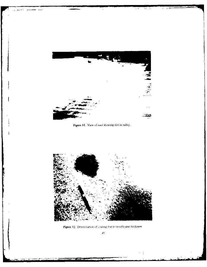
Figure 3 1. View of roof showing dirt in valley.
Fiur .4 Deeirto o,in (he to inmotticent thickness.,

I 10
Figure 33. Damage to coating from unknown missile.
*4.46
*rf
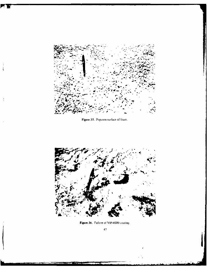
, -. 4. .•
-. o .o.--
.*. Jl ." , , . . .... • ,
Figure 35. Popcorn surface of foari.
II-Le
- .J .." , "-, " ' , S -".
dif_,. V" *O .. *Y o ,. " " '
a - ,, ,
-r.-. " ' • . -. ' "/ . . . - '
A. 4 .
w, • • li ' - 1 ..
Figure 36. Failure ofVIPa4000 coating.
47
-'p q.

foarn was applied. The coating used was aluminized density foam was applied. The foam surface was moreurethane AB-175 made by Performance Polymers ap- uniform in smoothness and texture than that observedplied to a dry film thickness of 20 to 25 mil (0.51 to at Sites 5 and 6. Conklin Rapid-Roof was applied, and0.64 mam). This coating is not UL listed. It has coni- part of this was covered with Gaco Western U66 bypletely failed, becoming disbonded from the foam mistake. The U66 appears to adhere satisfactorily to(Figure 37) and has lost its elastomeric properties. the Rapid-Roof, but application was performed only 9
months before the site visit.
In other areas, as much of the VIP coating as possible m
was scraped off the existing foam. The Performance Site 8 was completed in the summer of 1975. Al-Polymers material was then applied; it completely though performed long before the UL certification,disbonded from both the foam and the VIP coating in the construction corresponds to UL Construction No.low places where water had ponded (Figure 38). 136.23 One inch (25 mm) of 2 pcf (32 kg/m 3 ) density
foam was applied directly to the sloping roof of a pre-Two days before the site visit, some further recoat- fabricated steel building. The roof slopes at a ratio of
ing had been done using Gaco Western U66 urethane. one vertical to three horizontal, shedding all water. TheSome cracks had formed in the foam under the original foam was coated with 20 to 25 mil (0.51 to 0.63 mm)VIP coating. It was observed that the Gaco Western of United Coatings' Diathon. Much hail damage wasmaterial did not bridge these cracks (Figure 39). noted during the summer of 1979 (Figure 43). In most
cases, the coating is cracked, but in some it is goneSite 6. an enclosed shopping mall. was composed of completely, leaving small holes in the coating and de-
many retail stores of varying sizes. On one store, a pressions in the foam. Foam under and around theseleaky flashing of an existing BUR, at its junction with areas is saturated with water, which covers the surfacea second-story wall, had been repaired in 1972 by when pressed (Figure 44). One such area had a growthfoaming and coating with an acrylic latex paint. This of algae about 6-in. (152-mm) wide by 30-in. (760-ram)failed in 3 years. The loose paint was brushed off and long (Figure 45).United Coatings' Diathon was applied. After 5 years, itis still in good condition, but is on a vertical surface Summary of Site Visitsand water cannot accumulate on it.
Several of the conditions observed in both the foamThe roof of another store was repaired during the and coating appeared to be the result of poor applica-
late fall of 1979; a power broom and compressed air tion techniques. Site 5 appeared to exhibit deficiencieswere used to remove loose aggregate and dirt from in both application and material. All the sites installedthe existing BUR. One inch of 2 pcf (32 kg/m 3 ) den- before 1980 indicated that regular inspection andsity foam was applied and coated with Gaco Western maintenance are needed because rapid deteriorationU66. Ponding has not affected this material, but it was sets in once the coating is damaged.applied less than 1 year before the site visit. One partof this roof is continually ponded because water leaksfrom an air-conditioning cooling tower (Figure 40). 6 CONCLUSIONSAnother case of ponding was solved by cutting a drain-age trench in the foam itself and recoating (Figure 41). These conclusions are based on a few site visits inA nearby area was foamed at about the same time with the Middle West and discussions with roofing contrac-1-1/2 pcf (24 kg/m 3) density foam and also coated tors, building owners, and technical personnel at CELwith Gaco Western U66. This failed almost immedi- and BUREC.ately. probably because the foam was too weak tosupport foot traffic. Foot marks are plainly visible 1. Application of foam roofing (directly to decks)and the breaks in the coating all occur at these marks that meets UL Class A requirements is limited to cast-(Figure 42). in-place structural concrete decks and sloped steel
roofs typically used for Butler-type buildings; flutedAll foam observed at Sites 5 and 6 was very uneven metal roof decking is not included. Foam can only be
in quality and surface, with many high and low places. applied over fluted metal roof decks if a thermal bar-
Site 7 was completed during November 1979. Theoriginal roof was a two-ply BUR from which loose 23
"(.onstruction No. 136." Building Materials Directorygravel was removed; I in. (25 mm) of 2 pcf(32 kg/in 3 ) (LL, Januar) 1980).
48
('
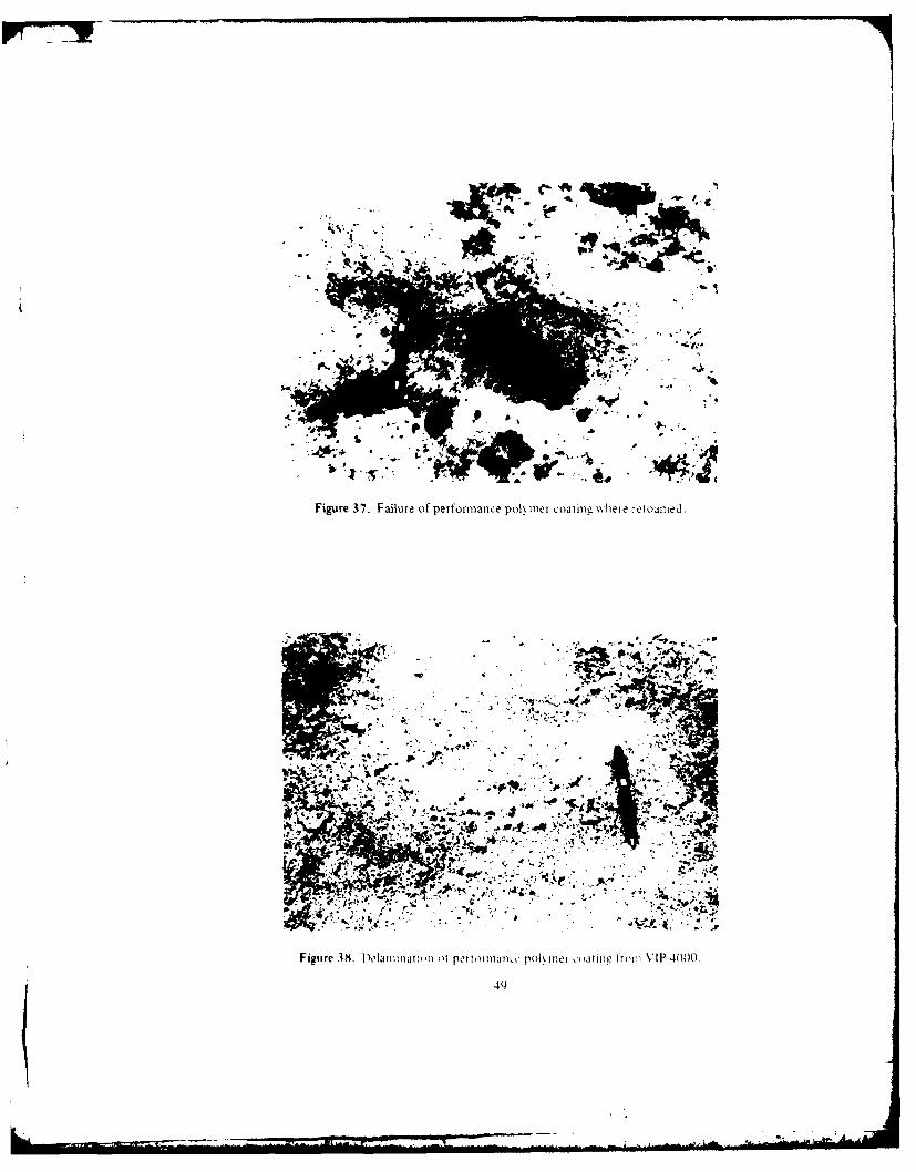
Il
I Vlf
'4Ir.
Figure 3. Foaminao o port ormanc po\ mer owtime wher rtlL) ime
49~

Figure 39. (Gaco Wkestern ['bo~. 2da\ old. not hiliJline cick in foamt.
Figure 40. I(MoiiJJ %0 iic io --, mi iomlwve in Ci
pA

Figure 41. Pond drained by cutting Irough in loam1.
-44-
igure 42. Footprint visihie (in 1-112 pcil11.. . . I ..

Figure 43. Ilail daniage to Diathon coating.
Figure 44. Saturated foam unde r IDia IIton coatinug.

foam ~ ~ ~ ~ aple to thi barir Fa mutawybep- ferislao, reurn exesv tratet.f.h
*b $
*' t"'.. -.
Figure 45. Algae growing on sloped roof.
t is first mechanically fastened to the deck and the be economically justifiable. Some fail within 2 yearsfoam applied to this barrier. Foam must always be ap- after installation, requiring extensive treatment of theplied so that water will drain from its surface, foam surface before the foam can be recoated.
2. Because of their different needs, Government 5. To prevent workmen from crushing the foamagencies disagree about the type of coating to be used, and fracturing the coating, a minimum of 40 psi
It was found that silicones and catalyzed (two-compo- (27.6 N/cm2 ) compres-tve strength is critical.nent) urethanes have the best service record of allcoatings for general use. One of the acrylics (Diathon) 6. Application of granules to the coating in somehas improved hail resistance if the film thickness is cases results in a tendency to hide hail damage ratherincreased from the manufacturer's recommended 20 than prevent it. On the other hand, granules add me-mls (0.51 mm) to 30 mils (0.76 mm). chanical strength to the coating and help prevent solar
3. The direction of water vapor flow must be degradation.
studied carefully when designing and selecting mate-rials for a foam roof application. As with any roof 7. CEG-07540, Elastomeric Roofing, Fluid-Ap-system, foam roofs above kitchens, laundries, and in- plied, for new construction, should be retained in its
door swimming pools, and similar services require a present form. However, the application of the system
vapor barrier between the roof deck and the foam to directly to sloped roofs or prefabricated steel Butler-
prevent migration of moisture into the foam from the type buildings should be permitted for retrofit purposes.
building interior. Conversely, roofs above cold storagefacilities such as meat lockers, refrigerated rooms, or 8. Because of the highly sensitive nature of foanfreezers require a vapor barrier above the foam to materials, users should be prepared to take special pre-prevent atmospheric moisture from penetrating the cautions with regard to temperature, moisture, wind,foam and condensing or freezing at the deck-to-foam and control of mechanical devices used for application.interface.
9. Coatings other than silicone should be permitted4. Although many coating materials have been rated for experimental installation only, with each applica-
for Class A application by UL, experience has shown tion requiring special authorization from the Majorthat they do not all have a service life long enough to Command or the Office of the Chief of Engineers.
53

REFERENCES
Alumbaugh, R. L. and J. R. Keeton, Investigation of Jones, B. V., Laboratory and Field Investigations ofSpray-Applied Polyurethane Foam Reroofing Sys- New Materials for Roof Construction, REC-ERC-tems, Technical Note N-1496 (Civil Engineering 76-4 (U.S. Department of the Interior, Bureau ofLaboratory, Naval Construction Battalion Center, Reclamation, April 1976).July 1977).
Asphalt Primer Used in Roofing, Damp-Proofing and Keeton, J. R., R. L. Alumbaugh, and E. F. Humm, Ex-
Waterproofing, ASTM D 41-78 (American Society perimental Polyurethane Foam Roofing Systems,ffor Testing and Materials [ASTM], 27 May 1980). Technical Note N-1450 (Civil Engineering Labora-
tory, Naval Construction Battalion Center, August
Building Materials Directory (Underwriters Labora- 1976).
tories, Inc. JUL], January 1980).
Marvin, E., et al., Evaluation of Alternative ReroofingConstruction Criteria Manual, DOD 4270. 1-M (Depart- Systems, Interim Report M-263/ADA071578 (U.S.
ment of Defense, October 1972). Army Construction Engineering Research Labora-
Coultrap, Keith H., Principles of Urethane Foam Roof tory, June 1979).
Application, PO No. 79-MR-461 (Civil EngineeringLaboratory, Naval Construction Battalion Center, Matson, W. H., Federation Series on Coatings Technol-June 1980). ogy, Unit Ten, Black and Metallic Pigments (Fed-
eration of Societies for Paint Technology, JanuaryCullen, W. C. and W. J. Rossiter, Guidelines for Selec- 1969), pp 29-37.
tion of and Use of Foam Polyurethane RoofingSystems, NBS Technical Note 778 (National Bureauof Standards, May 1973). Properties of Rigid Urethane Foams (Elastomer Chemi-
cals Department, E. 1. DuPont de Nemours and Co.,Elastomeric Roofing, Flu-Applied, Corps of Engineers n.d.)
Guide Specification (CEGS)-07540 (Department ofthe Army (DA], Office of the Chief of Engineers Standard Test Method for Transition Temperatures of[OCE], April 1980). Polymers by Thermal Analysis, ASTM D 3418
Fire Tests of Polyurethane Foam Roof Deck Construc- (ASTM, 1975).
tion on Steel Decks, Report CR 79.004 (Civil Engi-neering Laboratory, Naval Construction Battalion Tests for Fire Resistance of Roof Covering Materials,Center, December 1978). UL Standard 790 (UL, 1978).
54

LEK JPJi!bUJIDN
biner of Inainecrs Engr. Studies (i-nter. ATitN: library HS(HQ t"AHS' AIM N '
ATIN. T ,I Monitor Inst. for water Res., ATTN: Library ATTN I a' I s I j',,'
ATTN DMAIN-A SAP (2) Fiisintns Army MI. ''ATTN: OHN" (( SHAPE ... I f r , ..Amy"
ATW. DAI-CW AITN: Survivability Section, CAO-OPS Walter Ott t'n V .' .'
ATTN (CAIN (WE nfrastrurture Branch, LANDA UTAI I
AITT DAEN-(.WM .. HQ USLuCOM AT IN I ' T '
ATTN DAEN-CW( AITN: ECJ 4//il 0t ' tA T TN I)A I k -( W P
t ' "
ATTN DA[N MP Army Itl. nd Major At ivie I M
AIIM IjA0N MPL DAR(OM - Dir.. Inst.. A Muts.
AT1. IAIM Ml! AllM: laN iitt lnI. 'Cr' i'J. I.
ATTN :)A[ N MP ARRADI TM 091, t, '
A' 'N A' .-MPR A Aberdeen lIon itv,1o 1,rt'uI .
A''% JiA NPI) Army Mails. id Mi. ,lt .lnt , Rt'. ie. '
AT'h DAlM-RD Corpu, (hlristi Army lepot a'tr. hi P
0t 1 1MEN-RDM Harry Diamond ahoratorie' 1' MtI,. ., 11
ATTN OAFN-1RM Dugway Proving Iround ATTN , I
ATTN DAE-RM. Jefferson Proving hround ATN fi f ,'
A11Z DAN-ICE Fort Monmouth
ATTN DMM2(f,- Letterkenny Army Depot AITN 1'", ItP t I.
ITN: DAEN-ACM Natick Researth and lDev. (tr.
New [umbirland Army Depot ,At' it-t , I, it it
US Army Engineer Districts Pueblo Army Depot 0 1'.1 , A'1 j' T
ATTN: Library Red River Army Depot AIIN A TA 1,- i
Alaska Redstone Arsenal A1'n Alit -1
As batin Rock Island Arsenal ATTN f o ''. '
Albuquerque Savanna Army Depot (tierf inst. (I)-.. !. '.P
Bal timore Sharpe Army Depot
Buffalo Seneca Army Opot USA ARRL('M. Ait. t.
(harleston Tobyhanna Army Depot TAPCOM. fa(. li.
(hicaqo Tooele Army Depot TACOM, ATT '.
Detroit Watervliet Arsenal TSAPLC'M, Alt, I".
Far East Yuma Proving (round NARAD fTi. AlIt. Ii-NA'
sort Worth White ,ands Missili Range AMMP( . ATTN. (hi.t
Galveston 40 YVI:l
Huntingtt'n FORSCOM nO, nFtt ( -
'auksonville FOpSCOM Enginnnr. ATTA: AFEN-t I t. I
patt ATTN: Fa( Ii its innirers ATITl I/t fI -i
1,,n ,u [Ity Fort fuchavan Ho, /ito, Amy ' , i .
I Itilc Ro k Fort Pragq ATTN At T TI. 1;t
Los Angeles Fort CampbLouisville Fort Cdrson HO 11ARI F t .: J .rP
Memphis Fort Doevens GDCS/Lnqnrt'
Mobile Fort Drum AIIM: Ai.-''
Nashville Fort Hood V Corps
New Orleans Fort Indiantown Gap ATIN: AFTVD[(
"
New York Fort IrwinNorfolk Fort Sam Houston VII CorpsOmafha Fort Lewis ATTN: AE I "P '
Philadelphia Fort McCoy 7lst Support CI, ini
Pittburh Fort MtPherson ATIN AIIH t"
Portland Fort Geourge 6i. Miade
Riyadh Fort (ld tIT Amv cr, I
Rock Island Fort Polk ATTN AI1T'1, IN I.
Ia ranento Fort Richardson LIS Army ,h.1t 1' W i. V-"San Francisco Fort Riley ATIN: Atl -IN( 0TSanvanc o Presidio of San Francisco
Seattle Fort Sheridan (IS Arny nt lttn TI'( l;ii..
St. Louis Fort Stewart Europe
St. Pal Fort Wainwright ATIN: AFUL' PP
Tulsa Vancouver Bks. 8th USA. Korea
Vicksburg iRADOC ATIN: 0[Ai[
Walla Walla HQ TRADOC, ATTN: ATEN-FE Cdr, Fac [nqr A(t r)
Wilmlnqton ATiT: Facilities fngineer AFE. 2 osan Ara
'S Army Engineer Divisions Fort Belvoir ATE, ?D Ins 0V
ATTN: Library Fort Beninq AfE. Area 11 SPt !et
Lurope Fort Bliss AFt, Cp Humphreys
Huntsville Carlisle Barrarks AFt. Pusn
Lower Mississippi Valley Fort Chaffie AFE, Taplu
Middle East Fort Dix DLA ATIN: DIA-W
Middr fast (Rear) Fort Eustis
Missouri River Fort Gordon USA Japan (SA''
New Lngland Fort Hamilton Ch, FE iv. AJIN-il
North Atlantic Fort Benjamin Harrison Fac [nOr lHonshu)
North Central Fort Jackson Fac [nqr ('kinawa'
North Pacific Fort Knox RDOJUS Lo binetnr Fortes (C AaTrtAt1Nhio aier Fort Leavenworth ATTN: EUSA-HHC-(F- Ior,
Pacific Ocean Fort Lee
South Atlantic Fort McClellan 416th Enoinrer CoMnuanl
South Pacific Fort Monroe ATTN: Faciltes ltt0nerIi9
Southwestern Fort Rucker Norton AFFFort Sill ATTN: AFR( t MX (tl
Waterways Enperim'et Stat ion I ot I etiard WoodATTNI library IN "(I I h, Jlt I Iv, Port Ilunmt- N 11 otV49
nlit Anions R(searc h Iniioperinq I lt) ATN 1 i Jil l irI, Inq nier AIN I 1ii i (I t i. I t AI
ATtN: Lihrary Vint 1l11 1 artIs% '.tat ion All , Nt tt(i i .,itt "t k I
A Arlinlto O% H ,l ' .litton Tyndall All,. Is t ,'4t'
US roverirnmint Printing )ffi(eAntA.-ine 5 ction/Depository topics (2) WESICOM Thanute All', I1 tl'ATTN: faclljttIp% [nqineer., ( il ,SA' t
Defense Ternical Information Center fort Shattr
ATTN: F SA (at) National Guar Bureau
MoW Installation DCivisi'en
Engineering Societies Library ATTN: Facilities Engineer WASH DC /1.IL1
New York, NY Cameron Station
FESA, ATTN: Library Fort Lesley J. McNair
E L. ATTN: Library
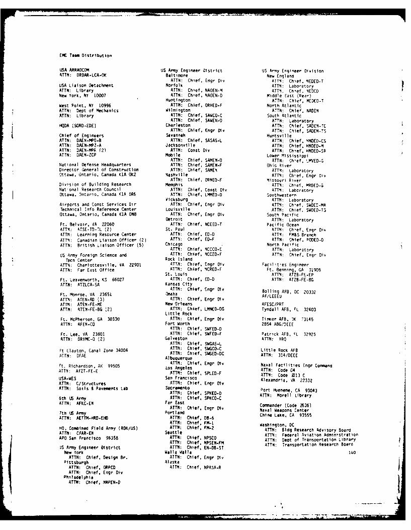
ENC Team Distribution
USA ARRAOCOM US Army Engineer District US Army Engineer DivisionATTN: DROAR-LCA-OK Baltimore New England
ATTN: Chief. Engr Div ATTN: Chief. NEOED-TUSA Liaison Detachment Norfolk ATTN: LaboratoryATTN: Library ATTN: Chief, NAOEN-M ATTN: Chief. NEDCONew York, NY 1OOO7 ATTN: Chief, NAOEN-O Middle East (Rear)
Huntington ATTN: Chief, MEDED-TWest Point. NY 10996 ATTN: Chief. ORHED-F North AtlanticATTN: Dept of Mechanics Wilmington ATTN: Chief, NADENATTN: Library ATTN: Chief. SAWCO-C South Atlantic
ATTN: Chief, SAWEN-D ATTN: LaboratoryHQOA (SGRD-EDE) Charleston ATTN: Chief. SADEN-TC
ATTN: Chief, Engr Div ATTN: Chief, SADEN-TSChief of Engineers Savannah HuntsvilleATTN: DAEN-MPO-B ATTN: Chief. SASAS-L ATTN: Chief, HNDED-CSATTN: DAEN-MPZ-A Jacksonville ATTN: Chief, HNDED-MATTN: DAEN-MPR (21 ATTN: Const Div ATTN: Chief, HNDED-SRATTN: DAEN-ZCP Mobile Lower Mississippi
ATTN: Chief, SAMEN-D ATTN: Chief, LMVED-GNational Defense Headquarters ATTN: Chief, SAMEN-F Ohio RiverDirector General of Construction ATTN: Chief, SAMEN ATTN: LaboratoryOttawa, Ontario, Canada KiA OK2 Nashville ATTN: Chief, Engr Div
ATTN: Chief, ORNED-F Missouri RiverDivision of Building Research Memphis ATTN: Chief, MRDED-GNational Research Council ATTN: Chief, Const Div ATTN: LaboratoryOttawa, Ontario, Canada KIA 0R6 ATTN: Chief, LMMED-D Southwestern
Vicksburg ATTN: LaboratoryAirports and Const Services Dir ATTN: Chief, Engr Div ATTN: Chief, SWDED-MATechnical Info Reference Center Louisville ATTN: Chief. SWDED-TGOttawa, Ontario, Canada KIA ON8 ATTN: Chief. Engr Div South Pacific
Detroit ATTN: LaboratoryFt. Belvoir, VA 22060 ATTN: Chief, NCEED-T Pacific OceanATTN: ATSE-TD-TL (2) St. Paul ATTN: Chief, Engr DivATTN: Learning Resource Center ATTN: Chief, ED-D ATTN: FM&S BranchATTN: Canadian Liaison Officer (2) ATTN: Chief. ED-F ATTN: Chief, PODED-DATTN: British Liaison Officer (5) Chicago North Pacific
ATTN: Chief, NCCCO-C ATTN: LaboratoryUS Army Foreign Science and ATTN: Chief, NCCED-F ATTN: Chief, Engr Div
Tecn Center Rock IslandATTN: Charlottesville, VA 22901 ATTN: Chief, Engr Div Facilities EngineerATTN: Far East Office ATTN: Chief, NCRED-F Ft. Benning, GA 31905
St. Louis ATTN: ATZB-FE-EPFt. Leavenworth, KS 66027 ATTN: Chief, ED-D ATTN: ATZB-FE-BGATTN: ATZLCA-SA Kansas City
ATTN: Chief. Engr Div Boiling AFB, DC 20332Ft. Monroe, VA 23651 Omaha AF/LEEEU
ATTN: ATEN-AD (3) ATTN: Chief, Engr DivATTN: ATEN-FE-ME New Orleans AFESC/PRTATTN: ATEN-FE-BG (2) ATTN: Chief, LMNED-OG Tyndall AFB, rL 32403
Little RockFt. McPherson, GA 30330 ATTN: Chief, Engr Div Tinker AFB, OK 73145ATTN: AFEN-CD Fort Worth 2854 ABG/DEEE
ATTN: Chief. SWFED-DFt. Lee, VA 23801 ATTN: Chief, SWFED-F Patrick AFB, FL 32925ATTN: DRXMC-O (2) Galveston ATTN: XRQ
ATTN: Chief, SWGAS-LFt Clayton, Canal Zone 34004 ATTN: Chief, SWGCO-C Little Rock AFBAT Cla ATTN: Chief, SWGED-OC ATTN: 314/DEEEATTN: OFAE Albuquerque
Ft. Richardson, AK 99505 ATTN: Chief, Engr Div Naval Facilities Engr CommandATTN: AFZT-FE-E LOS Angeles ATTN: Code 04ATTN: Chief, SPLED-F ATTN: Code X13 CUSA-WES San Francisco Alexandria, VA 22332ATTN: C/Structures ATTN: Chief, Engr DivATTN: Soils & Pavements Lab Sacramento Port Hueneme. CA 93043
ATTN: Chief, SPKED-O ATTN: Morell Library6th LIS Army ATTN: Chief, SPKCO-CATTN: AFKC-EN Far East ATTN Chef, ngrDivCommander (Code 2636)ATTN: Chief, Engr Dlv Naval Weapons Center
7th LIS Army Portland Nava wapen CenterATTN: AETTM-HRD-EHD ATTN: Chief, 9.6 China Lake, CA 93555
ATTN: Chief, FM-i Washington, DC
HO, Combined Field Army (ROK/US) ATTN: Chief, FM-2 ATn, dCAT:CA-NSeattle ATTN: Bldg Research Advisory BoardATTN CFAR-EN Seatt5e ATTN: Federal Aviation Administration
APO San Francisco 96358 ATTN: Chief, NPSCO ATTN: Dept of Transportation LibraryATTN: Chief, NPSEN-FM ATTN: Transportation Research BoardUS Army Engineer District ATTN: Chief, EN-DB-ST
New York Walla Walla 140ATTN: Chief, Design Br. ATTN: Chief, Engr Div
Pittsburgh AlaskaATTN: Chief, ORPCO ATTN: Chief, NPASA-RATTN: Chief, Engr Div
PhiladelphiaATTN: Chief, NAPEN-O
77 7-
Nat iona I Eiiginet'r inq | abora toryNjt llal llurvju ot Standard%
Civil Engineerinq Laboratory
Naval Construction Battalion Center
water P Power Resources Center
Denver Federal Center
Southern Division, NAVFAC
Code 406 (LBA)
Atlantic Division, NAVFACCode 406
NAVFAC HA
Code 0461
Oak Ridge National Laboratory
P.O. Box Y, Bldg 9204-1, MS-11
iQDA-DAEN-ROM
USAFESAAfTN: FESA-EB
CommanderFirst Coast Guard DistrictCivil Engineering Branch
3,2 Air Base Group/DEWilliams AFB
Commanding OfficerHQSAC/DEM'
SARRM-CO-FERocky Mountain Arsenal
HQ US Army Facilities Engineer Activity, Korea
ATTN: EAFE-E-ST
US Army Engineer Division Pacific Ocean
ATTN: PODED-T
- -
RosenfielJ, Myer J.Evaluation of sprayed polyurethane foa.a roofing and protective coatings. --
Chimpaign, IL : Construction Engineering Research Laboratory available fronNTIS, 19I1.
54 p. (Technical report ; M-297)
I. Roufing. 2. Urethane foam. I. Titln. II. Series U. S. Army.
Construction Engineering Research Laboratory. Technical report ;M-297.
'i•
iI