Embed Size (px)
Citation preview

E E 681 - Module 16
Path-oriented Survivable Mesh Networks Path-oriented Survivable Mesh Networks
W.D. Grover
TRLabs & University of Alberta© Wayne D. Grover 2002, 2003

E E 681 - Module 15 © Wayne D. Grover 2002, 2003
2
Three basic concepts about end-to-end path protection/restoration:
Shared Backup Path Protection– each working path has a (single) fully-disjoint backup route pre-determined at path-
provisioning time.– When needed a protection path is cross-connected from spare channels along the
backup route. – like “1+1 APS with a shared backup”– same end-node activated reaction regardless of where failure occurs on working path.
(“True”) Path Restoration– adaptive, failure-specific, response to failure and network state.– for each failure scenario the set of affected end-nodes are simultaneously restored with
an MCMF-like response. • has cognizance of the “mutual capacity” issue and global (or self-organized) coordination.
– Allows reuse of working capacity on surviving portion of failed paths.– Capacity design to assure 100% restorability to all defined scenarios.
GMPLS “mass redial”– completely ad-hoc reliance on mass independent re-provisioning attempts.– no co-ordination, self-organization, or other way to address mutual capacity
considerations – inherently unassured, best-efforts, unpredictable outcomes.
E E 681 - Module 15 © Wayne D. Grover 2002, 2003
3
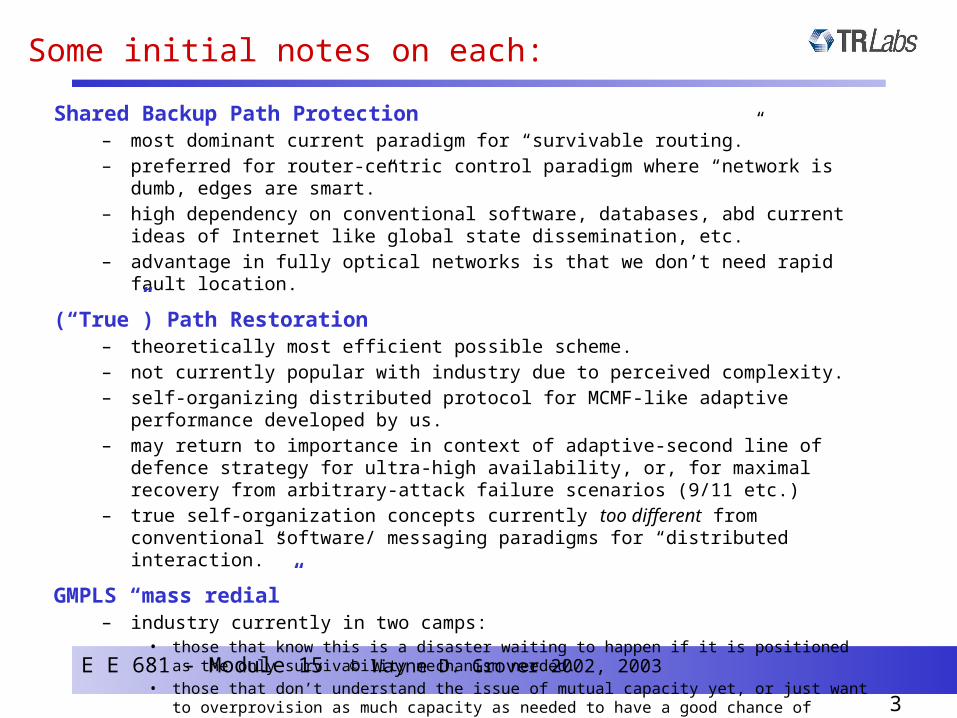
Some initial notes on each:
Shared Backup Path Protection– most dominant current paradigm for “survivable routing.”– preferred for router-centric control paradigm where “network is dumb, edges are smart.”– high dependency on conventional software, databases, abd current ideas of Internet like
global state dissemination, etc. – advantage in fully optical networks is that we don’t need rapid fault location.
(“True”) Path Restoration– theoretically most efficient possible scheme.– not currently popular with industry due to perceived complexity. – self-organizing distributed protocol for MCMF-like adaptive performance developed by us.– may return to importance in context of adaptive-second line of defence strategy for ultra-
high availability, or, for maximal recovery from arbitrary-attack failure scenarios (9/11 etc.)
– true self-organization concepts currently too different from conventional software/ messaging paradigms for “distributed interaction.”
GMPLS “mass redial”– industry currently in two camps:
• those that know this is a disaster waiting to happen if it is positioned as the only survivability mechanism needed.
• those that don’t understand the issue of mutual capacity yet, or just want to overprovision as much capacity as needed to have a good chance of restoration
– characterized in recent M.Sc. Thesis by G. Kaigala (and Globecom 2003 paper).

E E 681 - Module 15 © Wayne D. Grover 2002, 2003
4
Shared Backup Path Protection• “Protection” scheme (pre-determined fixed backup paths)
• End-to-end path protection
• Single protection path for each working path
• Spare capacity can be shared between disjoint working paths
• Restoration of path 1
• Restoration of path 2
Failure scenario 1
Failure scenario 2
Working path
Working path
Spare capacity re-use

E E 681 - Module 15 © Wayne D. Grover 2002, 2003
5
A slightly more general example of SBPP
Green-blue-yellow protection sharing (x3)
Green-red sharing (x2)

E E 681 - Module 15 © Wayne D. Grover 2002, 2003
9
0.0
0.5
1.0
1.5
2.0
2.5
3.0
3.5
4.0
4.5
5.0
0 1 2 3 4 5 6Sharing Limit
To
tal w
ave
len
gth
-dis
tan
ce c
ap
aci
ty
B-37B-40B-43B-46B-50
Cost of Limiting the Maximum Sharing Relationships*
Average total capacity increase for
F =2: 31.4%
Sharing Limit of 3 may be acceptable.
Average total capacity increase for
F=1: 150.4%
Average total capacity increase for
F =3: 5.1%
Sharing Relationship Limits of 1 and 2 yield total capacity increases that may be unacceptable.
* Results for test network family with varying nodal degree based on a 25 nodes - 50 spans master network

E E 681 - Module 15 © Wayne D. Grover 2002, 2003
10
Qualitative Appreciation of SBPP vs Span Restoration
Multiple restoration paths
Characteristics(relative to 1+1 APS)
Sp
an R
esto
rat i
on
SB
PP
Effect on capacity efficiency
Effect on availability
Sharing of spare capacity
Localized response
Distributed/adaptive restoration
Sharing of spare capacity
Single backup path
End-to-end response
Non-adaptive restoration
+ +
+ + +
+ ++
+ +
+-
- +
-
--
- - --
no effect
no effect

E E 681 - Module 15 © Wayne D. Grover 2002, 2003
11
“True” path restoration: what we mean
• The set of working paths severed by a span cut are restored by establishing a set of replacement paths end-to-end, simultaneously, between each O-D pair affected.
• The replacement paths are formed on-demand using only shared spare capacity (and possibly released working capacity (stub release).)
– There is no dedicated reservation of a 1-for-1 backup path for each working path.
• Path restoration is equivalent to abandoning the damaged pre-failure paths entirely and rapidly re-provisioning new paths end-to-end.
• Path restoration distributes the impact of failures and the recovery effort more widely over the network as a whole and therefore generally permits greater efficiency in spare capacity design.
• The capacity design and real-time restoration problems for path restoration are considerably more complex than span-restoration
– the fall-back to each O-D pair creates a capacitated multi-commodity max-flow problem.
E E 681 - Module 15 © Wayne D. Grover 2002, 2003
12
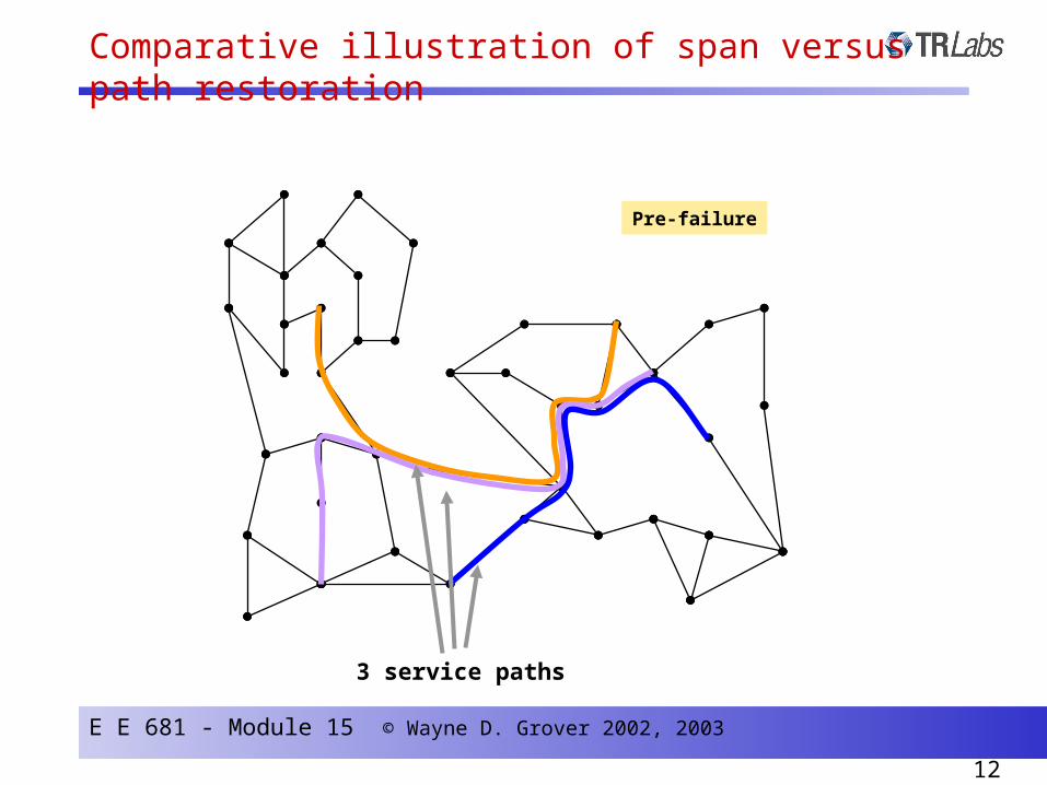
Comparative illustration of span versus path restoration
Pre-failure
3 service paths

E E 681 - Module 15 © Wayne D. Grover 2002, 2003
13
Failure occurs
Comparative illustration of span versus path restoration
All 3 service paths are lost
until …

E E 681 - Module 15 © Wayne D. Grover 2002, 2003
14
Span restoration reaction
First look at a span restoration reaction … (1)
Note: example only, exact routes depend on working and spare capacities
All 3 service paths are lost
until …
failed working links on failed
span are restored by
span restoration

E E 681 - Module 15 © Wayne D. Grover 2002, 2003
15
A span restoration reaction …(2)
Loopback / backhaul
Loopback / backhaul
This restoration path could stop hereThis restoration path could stop here

E E 681 - Module 15 © Wayne D. Grover 2002, 2003
16
Now view a path restoration reaction...
Same failure occurs

E E 681 - Module 15 © Wayne D. Grover 2002, 2003
17
A path restoration reaction …with “stub release” (1)
Path restoration action
Stub release
E E 681 - Module 15 © Wayne D. Grover 2002, 2003
18
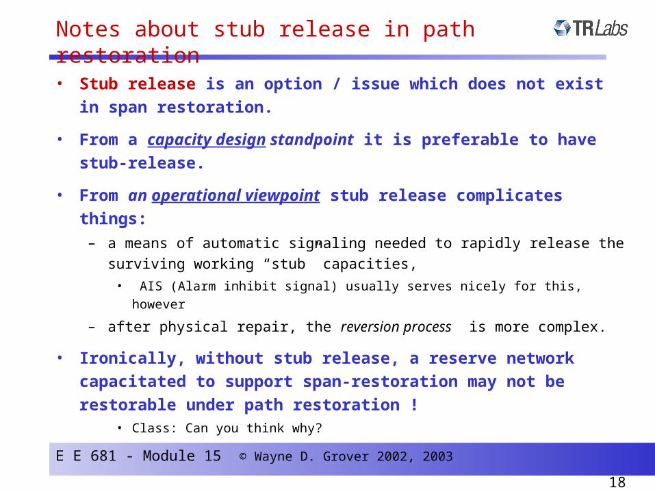
• Stub release is an option / issue which does not exist in span
restoration.
• From a capacity design standpoint it is preferable to have stub-
release.
• From an operational viewpoint stub release complicates things:
– a means of automatic signaling needed to rapidly release the surviving working
“stub” capacities,
• AIS (Alarm inhibit signal) usually serves nicely for this, however
– after physical repair, the reversion process is more complex.
• Ironically, without stub release, a reserve network capacitated to
support span-restoration may not be restorable under path
restoration ! • Class: Can you think why?
Notes about stub release in path restoration

E E 681 - Module 15 © Wayne D. Grover 2002, 2003
19
Optimal Capacity Design for Optimal Capacity Design for path- restorationpath- restoration
Approach that follows is to first develop a “master formulation” that can model joint / non-joint designs and cases with / without stub release, then discuss modifications for each special case.

E E 681 - Module 15 © Wayne D. Grover 2002, 2003
20
• The “master formulation” for path-restoration allows for:– modularity– joint optimization of working path routing– stub release or non-stub release
• The master formulation requires as inputs:– point-to-point demand
– a set of eligible distinct working routes for every (O-D) pair r– a set of eligible distinct restoration routes for every (O-D) pair r
for each failure scenario i .
• It solves for:– the amount of working flow on each working route for each O-D pair
(working flows may be split over several routes)– the working, spare, (and module) capacity totals on each span– the composite restoration path-set for all affected demands in each failure scenario
Note: in span restoration this isfor every span,
here it is for every OD pair.
Variations and options within the master formulation for path restoration

E E 681 - Module 15 © Wayne D. Grover 2002, 2003
21
mCj
rxi
,r qg
0
,si j
, prfi
,,r p
i j
riP
* some variables become pre-computable parameters in the variations that follow
Input data
Intermediate (internal) variables
Design output variables
Cost of mth modulesize on span j.
D
,r qj
S
rd
rQ
Set of all point to pointdemand quantities, indexed
by r
amount of demand on relation r
Set of all spans betweenmesh cross-connection points
Set of eligible working routes for relation r
Encodes routes in= 1 if span j is in qth route
for relation r
rQ
Set of eligible restoration routes for relation r
upon failure i.
= 1 if span j is in pth routefor relation r upon failure i
Stub release quantity on span j
from failure i
Amount of demand loston relation r for
failure i
mnj
jw
js
No. of operatingworking and spare
links (channels)on span j
No. of modules oftype m to install
on span j for min cost
mZCapacity of mth
module size
Working andrestoration
routingsolutions
N.B. “relation” = “OD pair”
Parameters and variables in path-restorable capacity design(in the master formulation)*

E E 681 - Module 15 © Wayne D. Grover 2002, 2003
22
B
A
fir,p
eligible restoration routes for A-B after the failure of span i,
workingroute for A-B
gr,q
Xir
span i
Qr = 1
Pir = 2
r = A-B
C
D
Orientation to the path restorable design context(variable and parameters)
E E 681 - Module 15 © Wayne D. Grover 2002, 2003
23
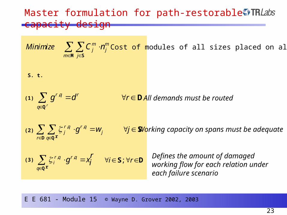
m mj j
m j
Minimize C n
M S
Cost of modules of all sizes placed on all spans
S. t.
;i r S D, ,r q r qi
q
rg xi
rQ
Defines the amount of damaged working flow for each relation under each failure scenario
,
r
r q r
q
g d
Q
r D
, ,r q r qj j
r q
g w
rD Q
j S
All demands must be routed
Working capacity on spans must be adequate
(1)
(2)
(3)
Master formulation for path-restorable capacity design

E E 681 - Module 15 © Wayne D. Grover 2002, 2003
24
, , ,
0
,0
r q r q r qj i
r q
gsi j
rD Q
With stub release
Without stub release
2( , )i j
i j
S
rP
,
p i
p rrf xii
;i r S D
0
rP
, ,,,
pr i
r p prf s si i i jjj
D
Restorability of working flows for each relation
Spare capacity on spans must be adequate (see note on stub release)
M
m
mmjjj Znws
1
j S Modularity of installed capacity
(4)
(5)
(6)
(7)
Master formulation for path-restorable capacity design (2)

E E 681 - Module 15 © Wayne D. Grover 2002, 2003
25
O D
Relation r
Route q
Failure span i
Other span j Working flow gr,q
, 1r qj
, 1r qi
Span j enjoys a stub release “credit” of spare capacity = g r,q for any
failure on span i such that: , ,( 1) ( 1)r q r qj i true
, , ,0
,r q r q r qj i
r q
s gi j
rD Q
Understanding how the formulation effects “stub-release”

E E 681 - Module 15 © Wayne D. Grover 2002, 2003
26
• joint optimizedrouting makes alargedifference in span restoration
Typical result comparing span and path-restorable network designs
4000
4200
4400
4600
4800
5000
1 2 3 4 5 6
To
tal N
etw
ork
Cap
aci
ty (
Lin
ks)
Combined workingand spare capacityoptimization
Spare capacityoptimization only
Design Case
Span restorablePath restorablePath restorablewith stub release
“non joint”
“joint” designs
• joint-span is aboutas efficient as non-joint path
• joint designadds relativelylittle benefit to path restoration

E E 681 - Module 15 © Wayne D. Grover 2002, 2003
27
• If integer (“ideal”) but non-modular capacity is desired:
– change objective function to cost-weighted sum of spares (and / or working, if joint)
– drop set M (the family of modularities), variables and constraint (7)
• If non-joint design is desired:
– drop (1), (2), (3), and (6)
– pre-compute all and as input parameters based on the pre-defined routing
– pre-compute all stub-release quantities according to (6)
• If stub-release is not desired:
– drop (6), i.e., set all = 0
mnj
rxi jw0,i js
Variations and options within the master formulation
0,i js

E E 681 - Module 15 © Wayne D. Grover 2002, 2003
28
• For each OD pair relation:– generate the set of “all distinct routes” between O-D with effectively unlimited
hop limit, e.g, H ~ 3/4 |S| and store in a (large) temporary routes file.
– sort the routes by increasing geographical length
– If joint formulation: • take first N routes (a budgeted number) as the set of eligible working routes for the
formulation. (Do not remove from file).
– If non-joint formulation:• take the single shortest route for the working paths between O-D
– For both joint or non-joint generate eligible restoration route-sets:• Repeat (for each active O-D pair):
– step out one span onto the shortest route, i – find first K routes in routes file which do not include span i as eligible restoration routes– remove chosen routes from file– go to next span along shortest route
Until last span in shortest route
• merge all routes found as eligible route-set for restoration of relation r.
A route-generating method for path restorable design formulation

E E 681 - Module 15 © Wayne D. Grover 2002, 2003
29
• What does this achieve ? – This procedure is effective in mediating the following trade-off in populating the route-
sets:
“All distinct routes”A single budgeted number
of distinct routes
Far too large DAT file sizesfor realistic AMPL / CPLEX runs
Insufficient diversity / uniform disjointness of route-sets found by Depth First Search, infeasibilities arising with even large route-set
budgets
project topic: write program to statistically sample the large eligible route space
Route generating method for path restorable formulation (2)

E E 681 - Module 15 © Wayne D. Grover 2002, 2003
30
O D
Boundary of a network graph
Outright infeasibility possible if all ‘budgeted’ routes neck
down onto one span in common
The preceding process for selecting routes stays within a budget but avoids this problem by
repeatedly pushing out the grey envelope as itproceeds in the direction across the network between
O-D nodes.
( Root end
of DFS tree )
( Leaf end
of DFS tree )
Observed tendency from taking budgeted number of distinct routes of successive length found by DFS
E E 681 - Module 15 © Wayne D. Grover 2002, 2003
31
A
B
C D
E
F
G
H
C
E
F
G
H
D
B
A
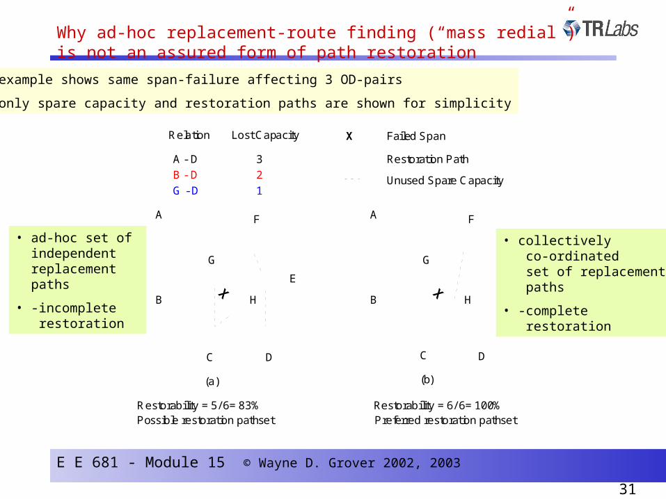
Relation Lost Capacity
A - D 3
B - D 2
G - D 1
Restoration Path
Unused Spare Capacity
Possible restoration pathset Preferred restoration pathsetRestorability = 6/ 6= 100%Restorability = 5/ 6= 83%
X Failed Span
(a) (b)
• example shows same span-failure affecting 3 OD-pairs
• only spare capacity and restoration paths are shown for simplicity
• ad-hoc set of independent replacement paths
• -incomplete restoration
• collectively co-ordinated set of replacement paths
• -complete restoration
Why ad-hoc replacement-route finding (“mass redial”)is not an assured form of path restoration

E E 681 - Module 15 © Wayne D. Grover 2002, 2003
32
• (1) A path restorable network inherently provides a response to node-failure and multiple span failures
- 100% restoration not guaranteed
- span restoration needs special extensions to the distributed protocols to respond to these situations as gracefully
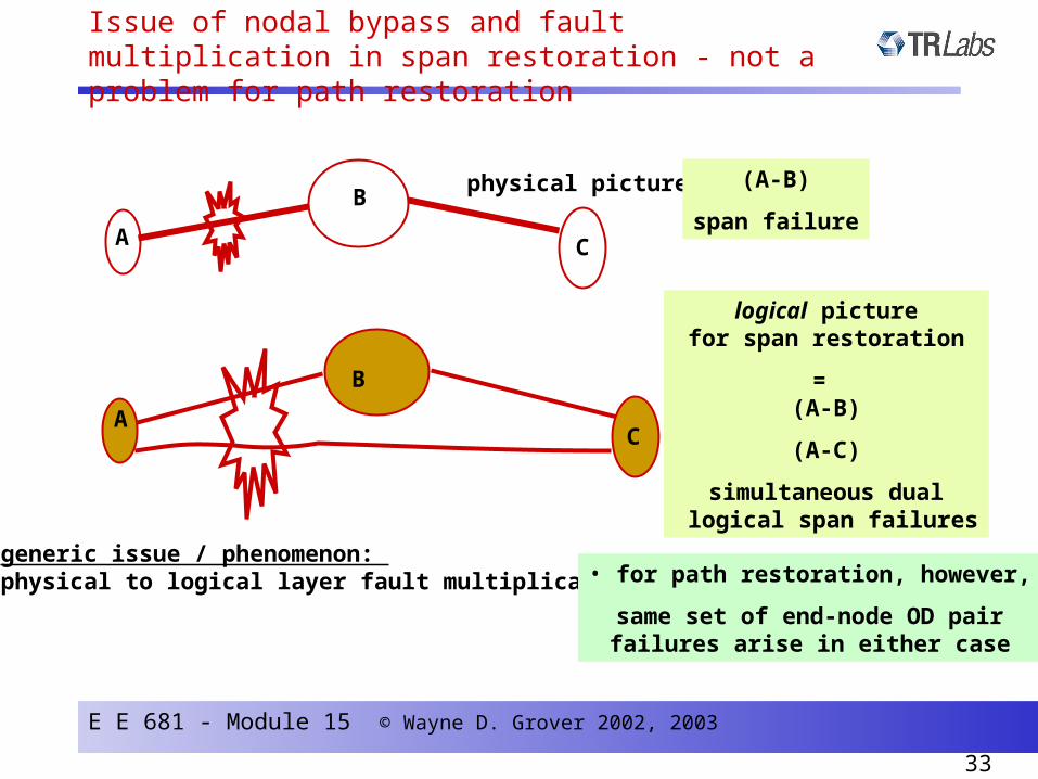
• (2) Path restoration also copes more gracefully with the multiple logical span failures arising from nodal “bypass” situations.
terminated flows
express or “bypass” flows
same cable
Other comments on path restoration
E E 681 - Module 15 © Wayne D. Grover 2002, 2003
33
physical picture =
logical picturefor span restoration
= (A-B)
(A-C)
simultaneous dual logical span failures
A C
B
AC
B
(A-B)
span failure
generic issue / phenomenon: physical to logical layer fault multiplication • for path restoration, however,
same set of end-node OD pairfailures arise in either case
Issue of nodal bypass and fault multiplication in span restoration - not a problem for path restoration

E E 681 - Module 15 © Wayne D. Grover 2002, 2003
34
• Recent findings indicate that the capacity benefit of path restoration (over span- restoration) may be considerably less than hoped for in low degree networks.....
chain
chain
higher degree mesh component
consider:
- intra chain demands
- demands that cross only one mesh span or chain----- >
can do no better -( spare capacity - wise) than with span restoration )
• for many demand pairs in a low degree network their path restoration solution is no different than span restoration in the mesh that results from collapsing all degree-2 chains.
Other comments on path restoration