Embed Size (px)
Citation preview

E-Coder-Digi-60 27/06/2016
E-CODER HOT FOIL PRINTER
WITH DIGI-60 CONTROLLER
OPERATOR INSTRUCTIONS PARTS LISTING
CIRCUIT DIAGRAMS INSTALLATION DETAILS
Designed and manufactured by:
OPEN DATE EQUIPMENT LIMITED PUMA TRADE PARK 145 MORDEN ROAD
MITCHAM SURREY, CR4 4DG. UNITED KINGDOM.
Tel: +44 (0)20 8655-4999
Email: [email protected] Web site: www.opendate.co.uk

E-Coder-Digi-60 27/06/2016
Declaration of Conformity. 3 Safety Instructions. 4 Operating Instructions. Digi-60 Electronic Controller 5 Electronic Control - Front Panel Layout 6 Electronic Control - Rear Panel Layout 7 Foil magazine Removal 8 Foil Threading 8 Re-fitting Foil Magazine 8 Type Holder Removal and Replacement 8 Foil Feed Adjustment 8 Printer - Foil Threading Diagram. 8 Initial Setting. 9 Print Orientation 9 Temperature Adjustment 9 Print Dwell Timer Adjustment 9 Air Flow Controls 10 Interconnection Details - Electrical and Pneumatic 11 Setting Up Digi-60 Controller 12 Temperature Mode Settings 13 Dip Switch Settings 14 & 15 Controller Connection Details 16, 17, 18 & 19 Temperature Calibration 20 Temperature Chart 21 Fault Finding. System Faults 22 Alarm Faults 23 Thermistor Faults 24 Mechanical Faults 25 Print Quality Problems 25 Machine Serial No. Identification 26 Recommended Spares Kit 27 Parts List - Body 28 Details Drawing - Body 29 Parts List - Cassette 30 Details Drawing - Cassette 31 Dimensions Datasheet. 32 Frame Installation Datasheet. 33 Airborne Noise Emissions. 34 Warranty 35 Open Date Group Companies, Agents & Distributors. 36
Index

E-Coder-Digi-60 27/06/2016
DECLARATION OF CONFORMITY
E-Coder-Digi-60 27/06/2016
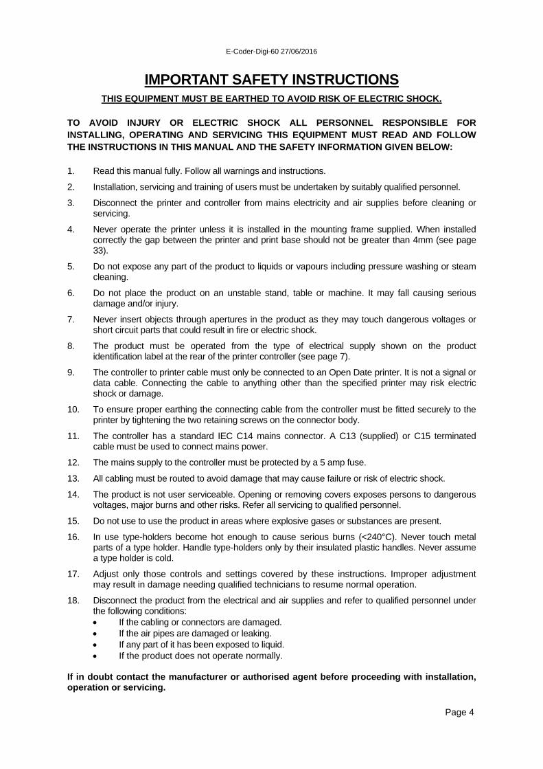
IMPORTANT SAFETY INSTRUCTIONS
THIS EQUIPMENT MUST BE EARTHED TO AVOID RISK OF ELECTRIC SHOCK. TO AVOID INJURY OR ELECTRIC SHOCK ALL PERSONNEL RESPONSIBLE FOR INSTALLING, OPERATING AND SERVICING THIS EQUIPMENT MUST READ AND FOLLOW THE INSTRUCTIONS IN THIS MANUAL AND THE SAFETY INFORMATION GIVEN BELOW: 1. Read this manual fully. Follow all warnings and instructions.
2. Installation, servicing and training of users must be undertaken by suitably qualified personnel.
3. Disconnect the printer and controller from mains electricity and air supplies before cleaning or servicing.
4. Never operate the printer unless it is installed in the mounting frame supplied. When installed correctly the gap between the printer and print base should not be greater than 4mm (see page 33).
5. Do not expose any part of the product to liquids or vapours including pressure washing or steam cleaning.
6. Do not place the product on an unstable stand, table or machine. It may fall causing serious damage and/or injury.
7. Never insert objects through apertures in the product as they may touch dangerous voltages or short circuit parts that could result in fire or electric shock.
8. The product must be operated from the type of electrical supply shown on the product identification label at the rear of the printer controller (see page 7).
9. The controller to printer cable must only be connected to an Open Date printer. It is not a signal or data cable. Connecting the cable to anything other than the specified printer may risk electric shock or damage.
10. To ensure proper earthing the connecting cable from the controller must be fitted securely to the printer by tightening the two retaining screws on the connector body.
11. The controller has a standard IEC C14 mains connector. A C13 (supplied) or C15 terminated cable must be used to connect mains power.
12. The mains supply to the controller must be protected by a 5 amp fuse.
13. All cabling must be routed to avoid damage that may cause failure or risk of electric shock.
14. The product is not user serviceable. Opening or removing covers exposes persons to dangerous voltages, major burns and other risks. Refer all servicing to qualified personnel.
15. Do not use to use the product in areas where explosive gases or substances are present.
16. In use type-holders become hot enough to cause serious burns (<240°C). Never touch metal parts of a type holder. Handle type-holders only by their insulated plastic handles. Never assume a type holder is cold.
17. Adjust only those controls and settings covered by these instructions. Improper adjustment may result in damage needing qualified technicians to resume normal operation.
18. Disconnect the product from the electrical and air supplies and refer to qualified personnel under the following conditions: If the cabling or connectors are damaged. If the air pipes are damaged or leaking. If any part of it has been exposed to liquid. If the product does not operate normally.
If in doubt contact the manufacturer or authorised agent before proceeding with installation, operation or servicing.
Page 4

E-Coder-Digi-60 27/06/2016
Digi-60 Controller Operating Instructions
Temperature button To adjust the temperature setting, press and hold down the temperature button and use the up/down arrow buttons to the left of the display to increase or decrease the set point. (Required Temperature)
Set point range:- Minimum 70ºC (158ºF), Maximum 240ºC (464ºF).
Note! When selecting operating Modes 1, 3 or 5, the printer will not operate on the external trigger until the temperature has reached the pre-programmed set point. (see page 13 for ranges of the mode settings etc.)
In normal operation the temperature will fluctuate by up to ±4ºc from the set point.
Print dwell button To adjust the print dwell setting, press and hold down the print dwell button and use the up/down arrow buttons to the left of the display to increase or decrease.
This adjustment controls the time the type/die face is in contact with the substrate. Higher numbers indicate longer dwell times.
Range: 10mS to 2000mS. (0.01 – 2.0 Seconds)
Print switch Switches the print signal between ON and OFF LINE. ON LINE; Green LED lit. The printer accepts external trigger signals
(automatic print cycle). The test button does not operate. OFF LINE; Green LED not lit. The printer does not accept external trigger
signals, The test button operates the printer. Note! Fault warnings automatically take the printer OFF LINE. When faults are cleared the printer can resume ON LINE status automatically or require a manual reset using the print switch. Refer to page 15 “Settings for ON LINE options” to use this feature.
Test Button. Manually triggers the printer when OFF LINE. (Green LED is not lit). Note! The test button is disabled when the printer is ON LINE
Fault warnings - Red LEDs Red LEDs indicate the fault conditions shown below. The printer goes OFF LINE when a fault is detected. (Refer to pages 22 & 23 for system faults)
Page 5
Air pressure Heater Foil Thermistor Door

E-Coder-Digi-60 27/06/2016
Page 6
Digi-60 Front Panel Layout
SET TEMP.
SET DWELL TEST PRINT
ON/OFF LINE
VALUE UP/DOWN
DOOR OPEN
AIR PRESSURE WARNING
THERMISTOR FAULT
ON LINE
FOIL FAULT / E.O.F.
HEATER FAULT
TEMP/DWELL VALUE

E-Coder-Digi-60 27/06/2016
Page 7 Page 7
Digi-60 Controller Rear Panel Layout
POWER SWITCH
MAINS INLET CONNECTOR
USER CABLE ENTRY
PRINTER CABLE OUTLET
For clarity cabling is not shown.
PRODUCT IDENTIFICATION LABEL Showing model number, serial number and mains supply requirements for the controller

E-Coder-Digi-60 27/06/2016
Operating Instructions - Printer MAGAZINE REMOVAL (see Diagram A. below) To remove the foil magazine, slide the black catch, hold in place and withdraw the magazine using the black handle. If the printer is on-line (Print LED on) the alarm will sound. Press the PRINT switch to silence this. FOIL THREADING (refer to Diagram B. below) 1. Fit an empty foil core onto the rewind mandrel. 2. Disengage the pinch drive roller. 3. Remove label from a new roll of foil. 4. Fit new roll of foil onto take-off mandrel (note unwind direction as shown on threading
diagram). 5. Thread foil around all rollers as shown on threading diagram. Note, the gloss side of the foil
should face inwards throughout the foil path. 6. Attach end of foil to empty core on rewind mandrel, gloss side facing inwards. 7. Wind foil on a few turn to track and tension it. 8. Engage pinch drive roller.
Foil Loading Diagram
Page 8
RE-FITTING FOIL MAGAZINE Hold the magazine by the handle, slide it onto the locating pins and push to lock in place. Press the PRINT switch on the control unit if the printer is to be put on-line. FITTING TYPE/DIE HOLDER NEVER ASSUME THAT A TYPE/DIE HOLDER IS COLD. Only pick up the type/die holder by its handle. Ensure that the face of the magnetic catch is clean, remove the foil magazine as detailed above, align the type/die holder within the two side locators and slide in until the magnet catches on the keep plate. Re-fit the foil magazine. FOIL FEED ADJUSTING SCREW (refer to Diagram A. above) This adjusts the amount of foil used per print. Winding the adjusting screw in reduces the foil pull and vice versa. Ensure that the locking nut is fully tightened after adjustment. A gap of 1 to 2mm is recommended between each portion of used foil.
Diagram A. Diagram B.

E-Coder-Digi-60 27/06/2016
Initial Setting Procedure
1. Ensure that printing foil and substrate are compatible. If in doubt, contact foil supplier for assistance.
2. Remove Type Holder from printer. 3. Ensure that rubber print base is clean, undamaged and securely retained in position under
printer. 4. Set air pressure regulator. 4 to 7 Bar is recommended (60 to 100 PSI). 5. Switch controller on. 6. Set print dwell time to 120 milli-seconds and temperature to 125ºc (257ºF). 3 to 4 minutes
should be allowed for printer to reach working temperature. 7. Load type or die into holder, centrally if possible and fasten securely. Make sure that typeface
is clean. 8. Load type/die holder into printer. If cold, allow 3 to 4 minutes for holder to heat up before
printing. 9. Ensure that the printer is off line. 10. Place a sample of substrate material under printer and press TEST button. Inspect resulting
print. 11. Adjust print levelling screws on the mounting frame until a light, uniform print impression is
achieved. Lock levelling screws. 12. Adjust foil metering screw for economic foil use as detailed previously and tighten thumb nut. 13. Switch the printer to on line for automatic operation. PRINT ORIENTATION To rotate the printer and therefore turn the overprint through 90 degrees, remove the foil magazine, unscrew the clamping handle until the location square on top of the printer is clear of the top rails, turn it to the required position, tighten the clamping handle and replace the magazine. TEMPERATURE ADJUSTMENT (Refer to Page 5) Normal setting is about 125ºc. (257ºF). Should the print not fully adhere to the substrate then a higher setting may be used. Small, fine detail print generally requires a lower temperature. Thermoplastic films and especially polyethylene generally require a lower temperature. Aluminium foils, paper and untreated polyester require a higher temperature. See pages 13 & 20 for temperature mode & calibration PRINT DWELL ADJUSTMENT (Refer to Page 5) Normal setting is about 120 milli-seconds. Generally, the larger the print, the higher the setting. Should the print not adhere fully to the substrate, a higher setting may be used. Remember, the printer can only operate during the stationary cycle of the web, if the print time
is longer than this the web may break. Should the dwell time have to be decreased to accommodate higher production speeds, it may
be necessary to compensate by increasing the temperature setting.
Page 9

E-Coder-Digi-60 27/06/2016
Air Flow Controls The airflow restrictors are usually attached to the solenoid valve exhaust ports. They work by regulating the speed at which air is exhausted from the air cylinder. Turning the adjusting screws will alter the exhaust airflow and consequently the print ram velocity, it will also affect noise levels. Increasing the exhaust airflow from the forward stroke of the print ram will increase the print pressure. Decreasing the exhaust airflow will reduce print pressure and the resulting print will be lighter. The drive for the printing foil is taken from the return stroke of the print ram. Increasing the exhaust airflow will speed up the foil feed. To ensure efficient foil feeding, the return stroke should be as gentle as possible. For higher speed operation, the exhaust airflow from both the forward and return strokes will have to be increased. Note, it is very important that the print ram returns fully before the next print cycle commences.
Solenoid Valve Details Refer to the diagram on page 11 for correct orientation of black and red air pipes to printer. Reversed printer air connections will force the print ram fully down (print position) instead of fully up (home position)
Air flow restrictor for print stroke
PORT 2 Black 6 mm air pipe to printer
Page 10
PORT 4 Red 6 mm air pipe to printer
Air flow restrictor For return stroke
PORT 1 Incoming air supply - 6mm tube.
4 - 7bar (60-100psi) Clean, dry air
Electrical connector. Refer to connection details on page 17

E-Coder-Digi-60 27/06/2016
E-Coder Connection Details
Page 11
E-CODER PRINTER
PRINTER CONNECTOR
(page 16,17)
PROTECTIVE EARTH Retaining screws must
be tightened to maintain earth continuity between printer and power supply.
(page 4 section 10)
AIR SUPPLY 6mm dia nylon tube
4 - 7bar (60 - 100psi) Clean, dry air.
AC MAINS SUPPLY
AIR SOLENOID VALVE ASSEMBLY
(pages 10, 16, 17)
PRINT TRIGGER SIGNAL
(page 16,17)
Digi-60 CONTROLLER

E-Coder-Digi-60 27/06/2016
Setting Up DIGI-60 Controller
Page 12
See page 14
See page 13
See page 15

E-Coder-Digi-60 27/06/2016
Digi-60 - Mode Settings for Temperature Tolerance Ranges
Page 13

E-Coder-Digi-60 27/06/2016
Digi-60 DIP Switch Settings
Page 14

E-Coder-Digi-60 27/06/2016
Thermistor & ON-LINE DIP Switch Settings (SW1)
Page 15

E-Coder-Digi-60 27/06/2016
Digi-60 Basic Connections (See page 17 for details)
Page 16
KEY TO COLOUR CODES: BK = black, BN = brown, RE = red, YE = yellow, GN = green, BU = blue,
PU = purple, WH = white, PK= pink, SC = screen or braid of cable
IMPORTANT—TO AVOID SHOCK RISK
THE PRINTER IS EARTHED VIA THE CONNECTOR AND BRAIDED SCREEN OF THE CONTROLLER CABLE. THE CONNECTOR RETAINING SCREWS MUST BE FULLY TIGHTENED FOR PROPER EARTHING. THE PRINTER MUST NOT BE USED IF THE CONNECTOR OR CABLE IS DAMAGED OR THE SCREEN IS NOT ATTACHED TO THE CONNECTOR BODY

E-Coder-Digi-60 27/06/2016
Digi-60 Connection Details
Page 17
PRINT TRIG PRINTER TRIGGER SIGNAL - grey 2 core screened cable. See page 14 print trigger selection for details of input print signals. P+ Red External trigger input + volts connection. P- Black/Blue External trigger input - volts connection. AIR VALVE PRINTER AIR SOLENOID VALVE - black 2 core unscreened cable. N.B. To avoid internal damage do not short these wires or allow them to be grounded. Be sure to use the correct terminals on the valve connector for +ive and -ive wires. S+ Red Air solenoid valve output +ive connection. Use terminal 1 on the connector S- Blue Air solenoid valve output -ive connection. Use terminal 2 on the connector PRINTER Multicore screened cable to D9 socket. N.B. Shock risk; mains voltage. See safety warnings on pages 4 and16. C/U Colour Function D Connector TH Yellow Thermistor connection. Pin 1 TH Green Thermistor connection. Pin 2 HE Red Heater LIVE connection. (230Vac!) Pin 3 HE Blue Heater NEUTRAL connection. (230Vac!) Pin 4 D1 Brown Door switch and foil sensor 0V. Pin 5 D2 Purple Door switch state. Pin 6 PM White Foil sensor. Printmaster only. Pin 7 F1 Black Foil sensor output. Pin 8 F2 Pink Foil sensor +24V. Pin 9 Screen Protective Earth. Connector body MAINS ELECTRICITY SUPPLY A standard IEC C14 connector is fitted to the rear of the controller This accepts the IEC C13 or C15 (hot condition) 3 pin connector (Commonly called a ‘Kettle’ lead) MAINS SAFETY - To avoid shock or fire hazards: The incoming mains supply must be protected by a 5A fuse. The controller must be earthed via the mains connector. Refer to page 4 for detailed safety information. For PRINT and FAULT relay connections refer to page 18 For AIR SW optional low air pressure warning refer to page 19

E-Coder-Digi-60 27/06/2016
DIGI-60 Fault and Print Relay Connections There are two relays for indicating printer system status to external equipment. The relays may be used independently or linked in series to obtain full warning status on a single connection. Each relay has COM, N/C and N/O contacts rated 24V @ 1A maximum Using the N/O contact of each relay gives a positive indication only when the printer is in normal/ready condition and the control voltage is present. (Fail safe operation) FAULT RELAY Changes state when a fault is detected. (door open, foil fail, heater fault, thermistor fault or low air pressure). PRINT RELAY Changes state when the printer is ON or OFF line.
Page 18
Wiring for Independent Fault/Print Indications
Wiring for Combined Fault/Print Indications
E-Coder-Digi-60 27/06/2016
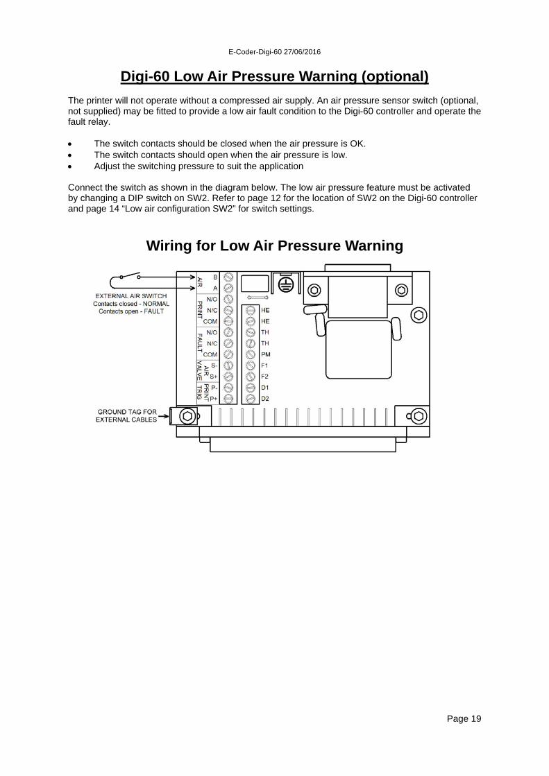
Digi-60 Low Air Pressure Warning (optional) The printer will not operate without a compressed air supply. An air pressure sensor switch (optional, not supplied) may be fitted to provide a low air fault condition to the Digi-60 controller and operate the fault relay. The switch contacts should be closed when the air pressure is OK. The switch contacts should open when the air pressure is low. Adjust the switching pressure to suit the application Connect the switch as shown in the diagram below. The low air pressure feature must be activated by changing a DIP switch on SW2. Refer to page 12 for the location of SW2 on the Digi-60 controller and page 14 “Low air configuration SW2” for switch settings.
Page 19
Wiring for Low Air Pressure Warning
E-Coder-Digi-60 27/06/2016
DIGI-60 Temperature Calibration
Note: Calibration Temperature Range = 70ºC to 220ºC (158ºF to 428ºF) The control unit is factory calibrated at 130ºC, and is set up in “MODE 1”supplied as standard. See page 13 for a list of the different modes available. Unless you are running temperatures outside the range 70ºC to 180ºC (158ºF to 356ºF), the default calibration should not be altered. Fitting of an alternative thermistor (THE 515002) will require (SW1) position to be altered (See page 15), again this will be accurate to plus or minus 7°C. If accurate temperatures are needed, you should recalibrate to suit the individual thermistor fitted. For normal running temperatures above 180°C you should recalibrate at 200°C. External Calibration Method Switch the Digi60 unit on and adjust the temperature setting to 130ºc or 266ºF. Leave on for 10 to 15 minutes, allowing the temperature to stabilise. Measure the temperature at the type face using a temperature probe. Allow the temperature probe to stabilise before noting the reading. Adjust the Digi60’s set point to match the temperature probe reading. Press the both the up and down arrow keys at the same time then press the print switch. The controller is now calibrated.
Page 20
E-Coder-Digi-60 27/06/2016
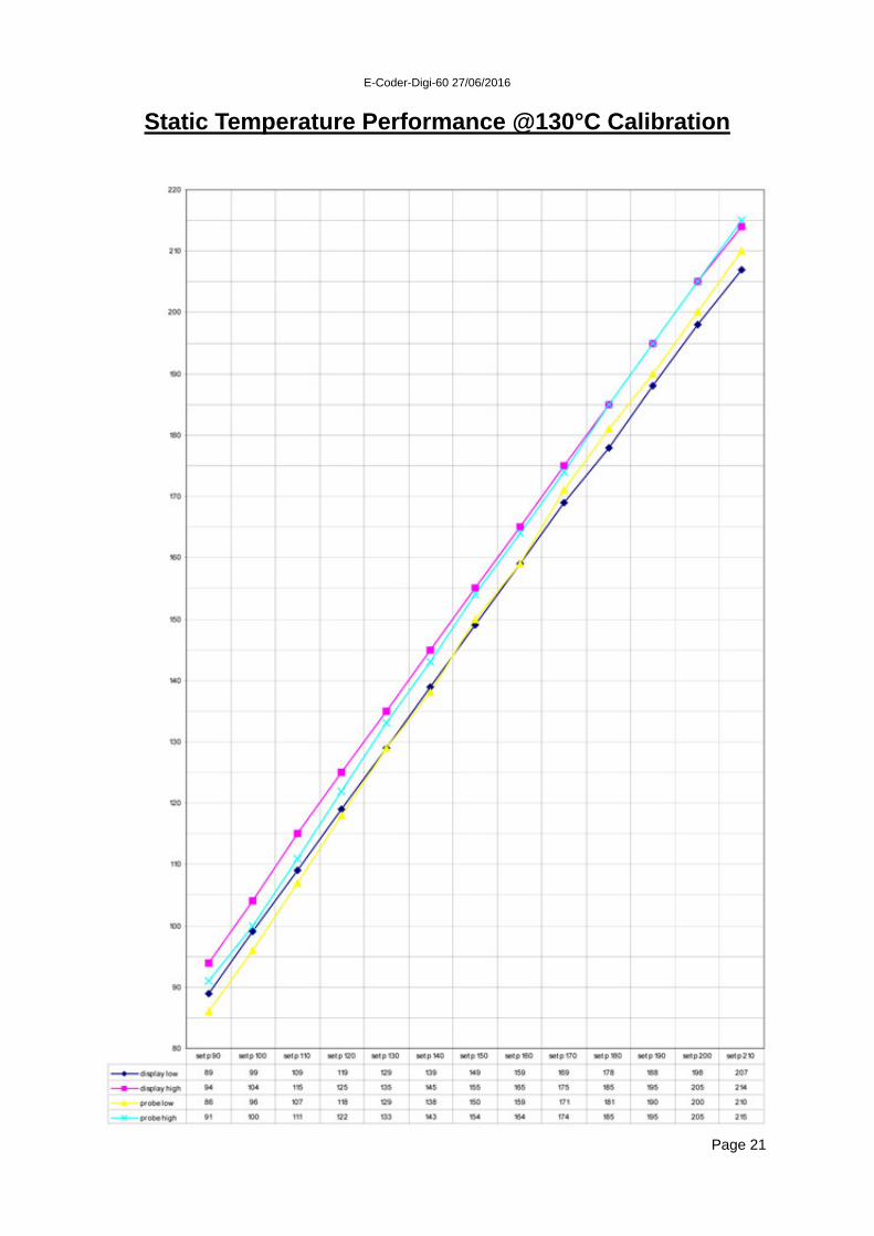
Static Temperature Performance @130°C Calibration
Page 21

E-Coder-Digi-60 27/06/2016
DIGI-60 System Fault Indications
Thermistor - Short circuit Red thermistor fault LED lit. Internal beeper sounding. Display shows “265” (or similar value). Heater disabled. Thermistor - Open circuit Red thermistor fault LED lit. Internal beeper sounding. Display shows “ 10” (or similar value). Heater disabled. Heater - Open circuit Red heater fault LED lit. Internal beeper sounding. Foil - Run out or broken Red foil fault LED lit. Internal beeper sounding. Type holder door open This feature is not available on E-Coder. Air pressure - Low Red heater fault LED lit. Internal beeper sounding. Note! Low air pressure warning uses an optional pressure switch. (see pages 14 and 19 for details).
In any of the above fault conditions, the fault relay will be de-energised. See pages 18 & 19 for connection details.
Page 22

E-Coder-Digi-60 27/06/2016
Digi-60 Alarm System Faults If no LEDs are on, check the mains supply and the fuses on the PCB. For wiring connections see
Page 23

E-Coder-Digi-60 27/06/2016
Thermistor Faults Digi-60 controller utilising the Open Date printer range and a standard thermistor.
NOTE. Results may vary, depending on type of Thermistor and actual temperature.
Page 24
Re-calibrate controller as detailed on page 20
E-Coder-Digi-60 27/06/2016
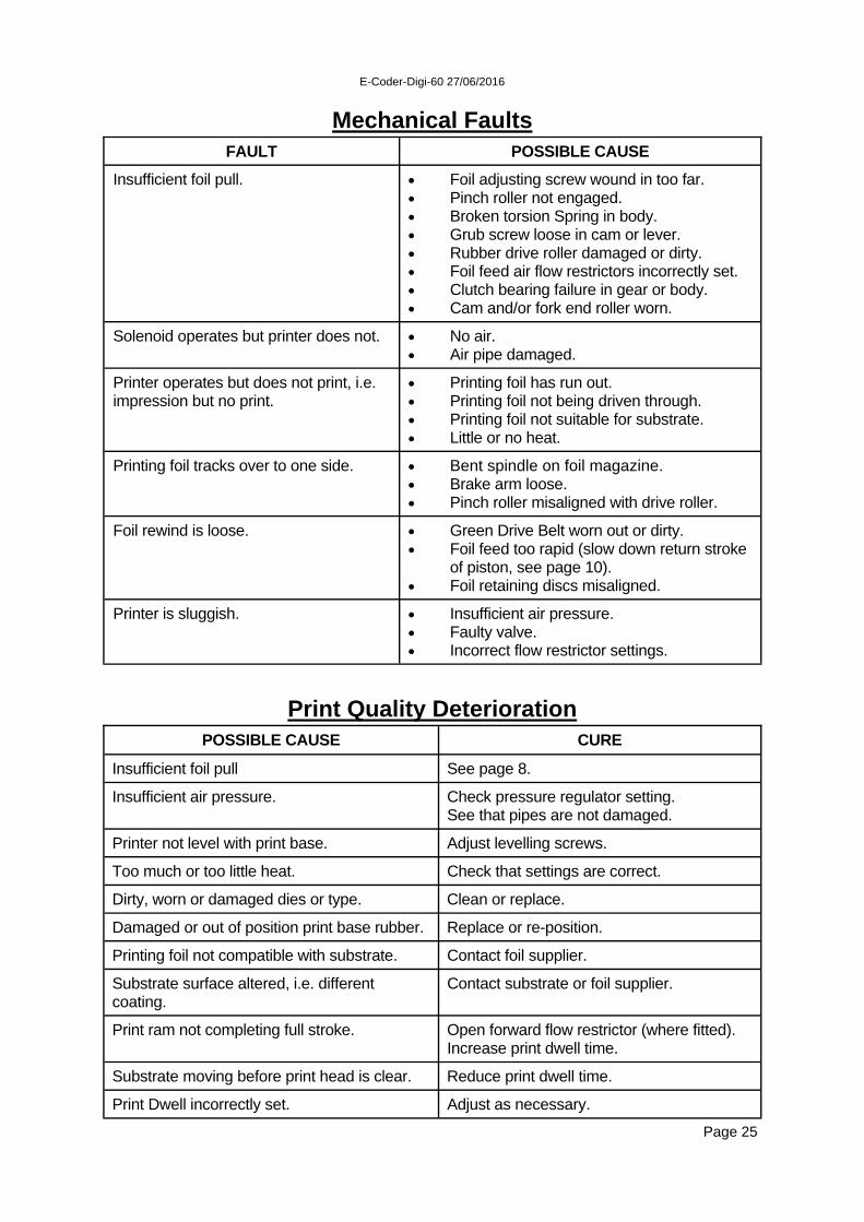
Mechanical Faults
FAULT POSSIBLE CAUSE
Insufficient foil pull. Foil adjusting screw wound in too far. Pinch roller not engaged. Broken torsion Spring in body. Grub screw loose in cam or lever. Rubber drive roller damaged or dirty. Foil feed air flow restrictors incorrectly set. Clutch bearing failure in gear or body. Cam and/or fork end roller worn.
Solenoid operates but printer does not. No air. Air pipe damaged.
Printer operates but does not print, i.e. impression but no print.
Printing foil has run out. Printing foil not being driven through. Printing foil not suitable for substrate. Little or no heat.
Printing foil tracks over to one side. Bent spindle on foil magazine. Brake arm loose. Pinch roller misaligned with drive roller.
Foil rewind is loose. Green Drive Belt worn out or dirty. Foil feed too rapid (slow down return stroke
of piston, see page 10). Foil retaining discs misaligned.
Printer is sluggish. Insufficient air pressure. Faulty valve. Incorrect flow restrictor settings.
POSSIBLE CAUSE CURE
Insufficient foil pull See page 8.
Insufficient air pressure. Check pressure regulator setting. See that pipes are not damaged.
Printer not level with print base. Adjust levelling screws.
Too much or too little heat. Check that settings are correct.
Dirty, worn or damaged dies or type. Clean or replace.
Damaged or out of position print base rubber. Replace or re-position.
Printing foil not compatible with substrate. Contact foil supplier.
Substrate surface altered, i.e. different coating.
Contact substrate or foil supplier.
Print ram not completing full stroke. Open forward flow restrictor (where fitted). Increase print dwell time.
Substrate moving before print head is clear. Reduce print dwell time.
Print Dwell incorrectly set. Adjust as necessary.
Print Quality Deterioration
Page 25

E-Coder-Digi-60 27/06/2016
Machine Serial Number Identification The printer identification label can be found on the outside of the printer, usually on the rear guard. The controller identification label can be found on the rear panel. Always quote the model and serial number when ordering spare parts.
MANUFACTURED
SERIAL NO.
MODEL
E-CODER
Open Date Equipment Ltd. Puma Trade Park, Mitcham, Surrey CR4 4DG. UK TEL: (020) 8655 4999 FAX: (020) 8655 4990
2016
Company Logo CE mark Type of machine
Serial number
Year of manufacture Manufacturer
123456
Page 26

E-Coder-Digi-60 27/06/2016
Recommended Spares List
Page 27
Covering: E-CODER MECHANICAL STOCK REF 1. Spring Set SPR620215 2. Drive Belt DRI620048 3. Drive Roller Assembly DRI620204 4. Fork End Roller Assembly FOR620208 5. Brake Strap BRA620038 6. Grey Self Adhesive Print Base SABASE 300 x 450mm sheet or 7. White Silicone Rubber Print Base SRBASE 300 x 300 x 3mm thick sheet ELECTRICAL 1. Cartridge Heater (240v) HEA501506 2. Thermistor Probe THE500522 3. Plug-In Control Card (see note below) 115v CPC293507 230v CPC293506 4. Pack of Fuses (5) FUS393500 5. Solenoid Valve without fittings VAL400020 Note. The stock reference for the plug-in Digi-60 control card listed above refers to the standard 240v, unit. Other variations are available which your printer may have been supplied with. If in doubt, please advise the serial number of your existing unit to our sales office.

E-Coder-Digi-60 27/06/2016
E-Coder Body Parts List
ITEM DESCRIPTION STOCK REF. QTY NOTES 49 Cylinder liner LIN620017 1 60 Main body N/A 1 61 Piston PIS620020 1 Piston/Seal assy ref. PIS620200 62 Bottom cap N/A 1 63 Data-box packing PAC190028 1 64 Guide pin PIN620022 1 65 Washer WAS620065 1 66 Needle Bearing BEA521008 1 67 Spindle SPI620059 1 68 Spring SPR530033 1 Part of Spring Set. 69 Cam CAM620025 1 70 Mounting plate PLA620026 1 71 Lock nut NUT620027 1 72/73 Foil adjusting screw assy ADJ620207 1 Includes item 91. 74 Dowel pin 2 3 dia x 10 75 Plug housing HOU130023 1 76 Drive spindle SPI620029 1 78 Timing pulley PUL620030 1 79 "O" ring O-R512005 1 Part of Seal Kit. 80 Rod seal SEA512038 2 Part of Seal Kit. 82 Nose bearing BEA620070 1 83 Piston seal SEA512036 1 Part of Seal Kit. 84 Bush BEA520017 1 86 Clutch Bearing BEA521507 1 87 Needle bearing BEA521001 1 89 "O" ring O-R512030 1 Part of Seal Kit. 90 Timing belt BEL522512 1 91 Roll pin 1 3 dia x 20 92 Cap screw 4 M6x20 93 Grub screw 1 M5x8 94 Button screw 10 M4x8 95 Lock nut 1 M10 99 Needle bearing BEA520018 1 100 Dowel pin 1 101 Cap screw 2 M3x25 102 Cap screw 4 M4x45 105 Grub screw 1 M8x8 106 CSK screw 2 M3x6 107 Side locator SID120014 2 108 Cushion DAM120074 2 109 Location pin LOC620517 2 110 lever LEV620110 1 111 Timing pulley assy PUL620219 1 Includes item 86. 113 Roller N/A 1 Part of item 121. 114 Insulating plate INS120012 1 115 Heater block HEA120013 1 116 Plug Assembly PLU399415 1 117 Mounting screw SCR120070 2 118 Keep plate KEE120030 1 119 Button screw 4 M5x8 120 Cover COV620034 1 121 Fork end assy FOR620208 1 Includes items 100,113. 122 Cap screw 1 M4x12 123 Top Cylinder Bearing BEA620064 1 125 Keep plate CAT620125 1 126 CSK screw 3 M4x10 133 Plug PLU620037 2 139 Sensor Mounting Block BLO620043 1 140 Cap Screw 2 M3x16 141 Foil Sensor ALA395018 142 Pan Head Screw 2 M2.5x10
Page 28
When ordering spare parts please use the Stock Reference. Item numbers refer to those on the following assembly drawings.

E-Coder-Digi-60 27/06/2016
E-Coder Body Assembly
Page 29

E-Coder-Digi-60 27/06/2016
E-Coder Cassette Parts List
ITEM DESCRIPTION STOCK REF. QTY NOTES 2a Take-off hub assy HUB620201 1 Includes items 26,44,50,56,57. 2b Rewind hub assy HUB620202 1 Includes items 26,42,44,50,54,55 3 Hub spindle SPI620003 2 5 Roller spindle SPI620005 6 6 Anchor ANC190006 1 7 Foil guide GUI620006 1 8 Bush BEA520004 2 9 Drive roller spindle SPI620007 1 12 Bush BUS190012 1 13 Drive roller assy DRI620204 1 14 Dancing arm assy ARM620226 1 18 Yoke assy YOK620206 1 Includes item 20, 19, 21 19 Spindle SPI620013 1 20 Pinch roller assy PIN620205 1 21 Pinch roller spindle SPI620015 1 23 Spacer SPA120042 1 25 Drive belt DRI620048 1 Part of Spring Set. 27 Brake strap BRA620038 1 29 Handle HAN530502 1 39 Spring SPR530008 1 Part of Spring Set. 51 Washer WAS120035 8 53 Handle HAN761072 1 58 Roller ROL620018 6 127 Thumb plate THU620127 1 131 Spring SPR530032 1 Part of Spring Set.
Page 30
When ordering spare parts please use the Stock Reference. Item numbers refer to those on the following assembly drawings.
ADDITIONAL SPARE PARTS & REPAIR KITS
STOCK REF PNEUMATIC Solenoid valve without fittings. VAL400020 ELECTRONIC Cartridge heater, 240v, 250w. HEA501506 Thermistor probe. THE500522 Plug-in Digi-60 printer control card; 115v CPC293507 230v CPC293506 For other control card variants please contact the sales office. REPAIR KITS Seal kit containing all seals. SEA620209

E-Coder-Digi-60 27/06/2016
E-Coder Magazine Assembly
Page 31

E-Coder-Digi-60 27/06/2016
E-Coder Dimensional Drawing
Page 32

E-Coder-Digi-60 27/06/2016
E-Coder Standard Frame Installation
Page 33

E-Coder-Digi-60 27/06/2016
E-Coder Airborne Noise Emissions
Comprehensive tests have been carried out with the Sprint fitted in a standard printer frame and mounted onto a typical label applicator. Measurements were taken at 1.6 metres above floor level and approximately 1 metre away from the printer in all directions. The measuring equipment used for conducting the tests was a Digital Sound Level Meter, type d-1405E supplied by Lucas CEL. Before the tests were carried out the instrument was calibrated and fitted with a foam windshield. The results shown below are based upon a standard type installation for the printer, the operating air pressure was set at 6 bar and the air flow restrictors correctly adjusted. The noise levels shown below are the equivalent continuous "A-weighted" sound pressure levels in decibels "dB(A)".
Page 34
PRINTS PER MINUTE NOISE LEVEL - DECIBELS (dB)
100 65
200 68
300 70
400 74

E-Coder-Digi-60 27/06/2016
Standard warranty terms & conditions for hot foil printers
All Open Date Hot Foil Printers Carry a twelve (12) month return to base (at our discretion) warranty. Open Date printers should be installed and operated according to the instructions given in the operating manual. No liability will be accepted for faults caused by incorrect installation or operation of the equipment or if the product has been altered or subjected to unreasonable use. The following components are not covered by the warranty as they will be subject to wear and tear: - 1. Print base rubber. 2. Type characters, dies and rotary data-box wheels. Should you have cause to claim for repair under warranty then please contact our service department stating the model, serial number of the product and the nature of the problem or fault. We reserve the right to charge for components replaced during the warranty period, which are subsequently found to be damaged due to any of the above conditions not being followed. Any items repaired or replaced under warranty will carry the balance of the original warranty period only.
Page 35

E-Coder-Digi-60 27/06/2016
Open Date Group Companies and Distributors
FRANCE OPEN DATE FRANCE Z.I. D’Attichy No.8, voie Industrielle 60350 Attichy. Tel:- +33 (0)3 44 42 94 43 Email:- [email protected] GERMANY OPEN DATE GmbH Mittler Stämmig 4 D - 97292 Üttingen Tel:- +49 (0)9369 9824 0 Email:- [email protected] USA OPEN DATE SYSTEMS, INC. Springfield Road PO Box 538 Georges Mills NH 03751-0538. Tel:- +1 603 763 3444 Email:- [email protected]
International Agents and Distributors
For a list of international agents & distributors visit www.opendate.co.uk
Page 36