Embed Size (px)
Citation preview

E Co 1/214th AVN Regt
C-12 Landing Gear

Retraction and Extension of the Landing Gear Is Done by a Hydraulic Power Pack, Located in the Left Wing Center Section
Forward of the Main Spar.

Landing Gear Power Pack

Power Pack Components• Hydraulic pump
• 28 vdc motor
• Gear selector valve and solenoid
• Two section fluid reservoir
• Filter screens
• Uplock pressure switch
• Low fluid level sensor

Landing Gear Power Pack and Hydraulic Plumbing

Hydraulic Lines for Normal Gear Extension Are Routed From the Power
Pack to the Nose and Main Gear.


• Nose gear downlock is accomplished by a lock in the nose gear actuator and the over-the-line action of the nose gear drag brace assembly.
• “J” hooks fitted to each main gear upper drag leg provides a positive down lock for main gear.
• An overload protection circuit located in the left wing center section forward of the main spar protects the system from electrical overload.

Nose Gear Actuator

Main Gear Wheel Well

Main Gear “J” Hook

Main Gear Up Switch

Main Gear Down Switch

C-12F Landing Gear Limitations
Airspeed• Extension: 181 KIAS• Extended: 181 KIAS• Retraction: 163 KIAS
Cycling• Observe one minute cooling time between
cycles (1 up - 1 down) with a 15 minute cooling time allowed after six cycles

C-12J Landing Gear Limitations
Airspeed• Extension, Extended, and Retraction: 180 KIAS
Cycling• Max number of consecutive gear cycles is three,
allowing two minutes between cycles• Allow five minutes between each additional cycle• After one hour with no gear activation, the cooling
interval reverts back to item 1
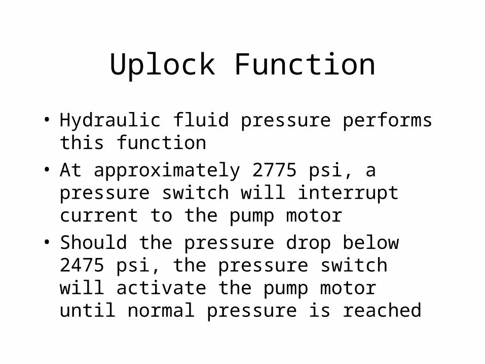
Uplock Function
• Hydraulic fluid pressure performs this function• At approximately 2775 psi, a pressure switch will
interrupt current to the pump motor• Should the pressure drop below 2475 psi, the
pressure switch will activate the pump motor until normal pressure is reached

Hydraulic Fluid
• The system uses MIL-H-5606• A caution light “HYD FLUID LOW” will
illuminate when the fluid level is low


![Landing Gear Accessories - goldlinequalityparts.com€¦ · 12 Landing Gear Accessories Landing Gear Accessories 13 [254.0mm] 10.00" [254.0mm] 10.00" [111.3mm] 4.38" [304.8mm] 12.00"](https://img.pdfslide.us/doc/110x75/5f42201687106b11477aac9b/landing-gear-accessories-12-landing-gear-accessories-landing-gear-accessories.jpg)
![arXiv:1407.0927v1 [cs.SE] 3 Jul 2014Landing-Gear Extended Landing-Gear Retracted Landing-Gear Box Landing Wheel Door Figure 1: Landing Gear System such as airport runways [11]. Three](https://img.pdfslide.us/doc/110x75/5e9397289f16a23cdf089611/arxiv14070927v1-csse-3-jul-2014-landing-gear-extended-landing-gear-retracted.jpg)